

Page 1

PACOpaQ™
HVAC Packaged Systems
Installation and Operating Instructions
GRUNDFOS INSTRUCTIONS
Page 2

Table of Contents
English (US) Installation and operating instructions
Original installation and operating instructions.
CONTENTS
Page
1. Symbols used in this document 3
2. Terms and Conditions 4
2.1 The contract 4
2.2 Price 4
2.3 Payment terms 4
2.4 Acceptance and inspection 4
2.5 Title and risk of loss 4
2.6 Patent or trademark information 4
2.7 Changes 4
2.8 Cancellation or termination 4
2.9 Delivery and delays 4
2.10 Warranty 5
2.11 Technical documents 5
2.12 Limitation of liability 5
2.13 This company is an equal opportunity 5
employer
2.14 Law and arbitration 5
3. PACOpaQ system installation 6
3.1 General instructions 6
3.2 Lifting and rigging instructions 6
3.3 Storage 6
3.4 Bolt check instruction 6
3.5 Field connection 6
3.6 Assembly of packaged sections (if applicable) 7
3.7 Other package system requirements 7
4. Pump Installation-Mechanical 8
4.1 Pump Identication 8
4.2 Receiving 8
4.3 Temporary storage 8
4.4 Location 8
4.5 Horizontal pump foundation 8
4.6 Securing base plate 9
4.7 Vertical mounting instructions 9
4.8 Piping-general 9
4.9 Suction (inlet) piping 9
4.10 Discharge (outlet) piping 10
4.11 Shaft, sealing-general comments 10
4.12 Packing gland adjustment 10
4.13 Mechanical seals 10
4.14 Coupling alignment (LF) 11
4.15 Coupling alignment (LCS) 11
5. Pump Installation-electrical 11
5.1 Motors general 11
5.2 Installation wiring 11
6. Pump operation 12
6.1 Priming 12
6.2 Pre-start checklist 12
6.3 Motor rotation 12
6.4 Starting the pump 12
6.5 Voltage regulation 13
6.6 Pump shutdown 13
6.7 Short duration shutdown 13
6.8 Extended period shutdown 13
7. Pump Maintenance 13
7.1 Motor lubrication 13
7.2 Pump lubrication 14
7.3 Disassembly of pumps 14
7.3.1 Disassembly of liquid end 14
7.3.2 Disassembly of bearing frame (LF) 14
7.4 Seal replacement (LCS) 14
7.5 Wear ring replacement 15
7.6 Reassembly of pumps 15
7.7 Ordering parts 16
7.8 Type LF, cross section and parts list 17
7.9 Type LC, cross section and parts list 18
7.10 Type LCV, cross section and parts list 19
7.11 Type LCS, cross section and parts list
8. Pump Troubleshooting 21
8.1 Symptom 21
8.2 Possible causes 21
9. Grundfos CUE Variable Frequency Drive 22
9.1 CUE introduction 22
9.2 General description 22
9.3 Applications 23
9.4 References 23
10. CUE safety and warnings 23
10.1 Warning 23
10.2 Safety regulations 23
10.3 Installation requirements 23
10.4 Reduced performance under certain conditions 23
11. Identication 23
11.1 Nameplate 23
11.2 Packaging label 23
12. CUE installation-mechanical 23
12.1 Reception and storage 23
12.2 Transportation and unpacking 23
12.3 Space requirements and air circulation 24
12.4 Mounting 24
13. Electrical connection 24
13.1 Electrical protection 24
13.2 Mains and motor connection 25
13.3 Connecting the signal terminals 30
13.4 Connecting the signal relays 32
13.5
13.6 EMC-correct installation 34
13.7 RFI lters 34
13.8 Output lters 34
14. CUE operating modes 35
15. CUE control modes 35
15.1 Uncontrolled operation (open loop) 35
15.2 Controlled operation (closed loop) 36
16. Menu overview 37
17. Setting by means of the cotnrol panel 40
17.1 Control panel 40
17.2 Back to factory setting 40
17.3 Start-up guide 41
17.4 Menu GENERAL 45
Connecting the MCB 114 sensor input module 33
20
2
Page 3

17.5 Menu OPERATION 45
7. Trouble Shooting
18
7.1 Symptom
18
7.2 Possible Causes
18
Caution
Note
Note
17.6 Menu STATUS 46
17.7 Menu INSTALLATION 48
18. Setting by means of PC Tools E-products 55
19. Priority of setttings 56
19.1 Control without bus signal, local operating 56
mode
19.2 Control with bus signal, remote-controlled 56
operating mode
20. External control signals 56
20.1 Digital inputs 57
20.2 External setpoint 57
20.3 GENibus signal 57
20.4 Other bus standards 57
21. CUE Maintenance and service 57
21.1 Cleaning the CUE 57
21.2 Service parts and servie kits 57
22. CUE Troubleshooting 58
22.1 Warning and alarm list 58
22.2 Resetting of alarms 58
22.3 Indicator lights 58
22.4 Signal relays 58
23. Technical data 59
23.1 Enclosure 59
23.2 Main dimensions and weight
23.3 Surroundings 60
23.4 Terminal tightening torques 60
23.5 Cable length 61
23.6 Fuses and cable gauge size 61
23.7 Inputs and putputs 63
23.8 Sound pressure level 63
24. Disposal 63
25. CU 352 product description 64
25.1 Indicator lights 64
25.2 Terminals 64
25.3 Potentially explosive environments
26. Identication
27. CU352 installation 65
27.1 Location 66
27.2 Enclosure class 66
27.3 Terminals 66
27.4 Cables 66
28. CU 352 Installation-Mechanical 66
29. EMC-correct installation 67
29.1 Internal GENibus connection 68
29.2 Fieldbus communication interface 68
modules
29.3 Fitting the CIM module 69
30. CU 352 Startup 70
31. Technical data 70
32. Electrical data 70
32.1 Supply voltage 70
32.2 Power consumption 70
32.3 Circuit breaker 70
32.4 Backup fuse 70
32.5 Short-circuit protection 70
60
64
65
32.6 Digital inputs
32.7 Analog inputs
70
70
32.8 Digital outputs (relay putputs) 70
32.9 Conductors 70
32.10 USB port 70
32.11 Battery backup (UPS) 71
32.12 Terminal groups 71
33. Overview of inputs and outputs 72
34. CU 352 Maintenance 73
35. CU 352 Service
73
36. Replacing the CU 352 73
36.1 Replacing the CIM module
73
37. CU 352 Dimensions 73
38. CU 352 Disposal 73
39. Suctiondiuser-IOM 74
39.1 Installation 74
39.2 Operation and maintenance 74
39.3 Sectional drawing and components 74
1. Symbols used in this document
The following symbols may be used in this document.
Warning
If these safety instructions are not observed,
it may result in personal injury.
Warning
If these instructions are not observed, it may lead
to electric shock with consequent risk of serious
personal injury or death.
Warning
When pumping hazardous liquids, special
attention must be paid to the risk of personal
injury.
Warning
The surface of the product may be so hot that
it may cause burns or personal injury.
Warning
The sound pressure level is so high that hearing
protection must be used.
If these safety instructions are not observed,
it may result in malfunction or damage to the
equipment.
Notes or instructions that make the job easier
and ensure safe operation.
Table of Contents
3
Page 4

English (US)
Terms and Conditions
2. Terms and Conditions
2.1 The contract
The Contract shall be comprised of the following terms, together
with such terms and conditions as are set forth in Seller's written
proposal or quotation (the "Quotation"), including any documents,
drawings or specifications incorporated t
any additional or different terms proposed in Buyer's purchase
order (the "Purchase Order") that are accepted by Seller in
writing, which together shall constitute the entire agreement
between the parties, provided, however, that preprinted terms on
Buyer's purchase order or invoice shall not apply and Seller gives
notice of objection to such terms. An offer by Seller in its
Quotation that does not stipulate an acceptance date is not
binding. This Contract shall be deemed to have been entered into
upon written acknowledgment of the Purchase Order by an officer
or authorized representative of Seller, which may not be modified,
supplemented, or waived except in a writing executed by an
authorized representative of the party to be bound.
2.2 Price
The price quoted in the Quotation shall be the Purchase Price
unless otherwise agreed in the Purchase Order. The Purchase
Price for equipment shall include packing for shipment. Field
Services shall be provided at Seller's standard rates. All other
costs, including packing for storage, freight, insurance, taxes,
customs duties and import/export fees, or any other item not
specified in the Contract, shall be paid by Buyer unless
separately stated in the Quotation and included in the price
quoted. Any sales, use, or other taxes and duties imposed on the
transaction or the equipment supplied shall be paid or reimbursed
by Buyer.
2.3 Payment terms
Payment shall be due within 30 days of the date of Seller's
invoice in U.S. funds unless otherwise agreed. If Buyer does not
observe the agreed dates of payment, Buyer shall pay interest to
Seller on overdue amounts at a rate that is the higher of: 9 % per
annum or a rate 5 % in excess of the rate borne from time to time
by new issues of six-month United States Treasury bills. Seller
shall be entitled to issue its invoice for the Purchase Price for
equipment upon the earlier of shipment, or notice to Buyer that
Seller is ready to ship, and for services, upon completion. If the
Purchase Price exceeds $250,000 USD, Buyer shall pay the
Purchase Price in Progress payments as follows: Fifteen percent
(15 %) upon submittal of general arrangement drawings, thirty
five percent (35 %) after receipt of first Bowl Casting, twenty
percent (20 %) after first case/bowl hydro test or bowl machining
and thirty percent (30 %) after notification of ready to ship.
2.4 Acceptance and inspection
All equipment shall be finally inspected and accepted by Buyer
within 14 days after delivery or such other period of time as is
agreed in the Purchase Order. Buyer shall make all claims
(including claims for shortages), excepting only those provided
for under the warranty clause contained herein, in writing within
such 14 day period or they are waived. Services shall be
accepted upon completion. Buyer shall not revoke its acceptance.
Buyer may reject the equipment only for defects that substantially
impair its value, and Buyer's remedy for lesser defects shall be in
accordance with Section 10, Warranty. If tests are made by Buyer
to demonstrate the ability of the equipment to operate under the
contract conditions and to fulfill the warranties in Section 10,
Buyer is to make all preparations and incur all expenses
incidental to such tests. Seller will have the right of representation
at such tests at its expense, and the right to technically direct the
operation of the equipment during such tests, including requiring
a preliminary run for adjustments.
herein by reference, and
2.5 Title and risk of loss
Full risk of loss (including transportation delays and losses) shall
pass to Buyer upon delivery, regardless of whether title has
passed to Buyer, transport is arranged or supervised by Seller, or
start-up is carried out under the direction or supervision of Seller.
Delivery shall be ex works, INCOTERMS 2000. Loss or
destruction of the equipment or injury or damage to the
equipment that occurs while the risk of such loss or damage is
borne by Buyer does not relieve Buyer of its obligation to pay
Seller for the equipment.
2.6 Patent or trademark information
If the equipment sold he
manufactured according to Buyer's specifications, Buyer shall
indemnify Seller and hold it harmless from any claims or liability
r patent or trademark infringement on account of the sale of
fo
such goods.
reunder is to be prepared or
2.7 Changes
Buyer may request, in writing, changes in the design, drawings,
specifications, shipping instructions, and shipment schedules of
the equipment. As promptly as practicable after receipt of such
request, Seller will advise Buyer what amendments to the
Contract, if any, may be necessitated by such requested
changes, including but not limited to amendment of the Purchase
Price, specifications, shipment schedule, or date of delivery. Any
changes agreed upon by the parties shall be evidenced by a
Change Order signed by both parties.
2.8
Buyer shall have the right to cancel the Contract upon 15 day
prior
upo
Buyer. If Buyer cancels the Contract, it shall pay: (a) the agreed
unit price for equipment or components completed and delivered,
(b) additional material and labor costs incurred, and for
engineering services supplied by Seller with respect to the
canceled items, which shall be charged to Buyer at Seller's rates
n effect at the time of cancellation, but which shall not exceed the
i
contract price for such items, and (c) such other costs and
expenses, including cancellation charges under subcontracts, as
Seller may incur in connection with such cancellation or
termination.
ellation or
Canc
en notice
writt
n the receipt of such notice except as otherwise agreed with
ermination
t
s'
to Seller, and Seller shall stop its performance
2.9 Delivery and delays
Seller shall use its best efforts to meet quoted delivery dates,
which are estimated based on conditions known at the time 16
A1d.1 606 supercedes 9/05 PACO PUMPS of quotation. Seller
shall not be liable for any nonperformance, loss, damage, or
delay due to war, riots, fire, flood, strikes or other labor difficulty,
governmental actions, acts of God, acts of the Buyer or its
customer, delays in transportation, inability to obtain necessary
labor or materials from usual sources, or other causes beyond the
reasonable control of Seller. In the event of delay in performance
due to any such cause, the date of delivery or time for completion
will be extended to reflect the length of time lost by reason of
such delay. Seller shall not be liable for any loss or damage to
Buyer resulting from any delay in delivery.
4
Page 5

2.10 Warranty
English (US)
3.2 Receiving
• Check pumping unit for shortage and damage immediately
upon arrival. Pump accessories when required are packaged
in a separate container and shipped with the unit.
• If equipment is damaged in transit, promptly report this to the
carrier's agent. Make complete notations on the freight bill to
speed satisfactory adjustment by the carrier.
• Unload and handle the unit with a sling. Do not lift unit by eye
bolts on the motor!
3.3 Temporary storage
• If pump is not to be installed and operated soon after arrival,
store it in a clean, dry area of moderate ambient temperature.
English (US)
2.14 law and arbitration
The Contract shall be governed by the law of the State of Texas.
Any disputes arising out of this Contract shall be resolved by
informal mediation in any manner that the parties may agree
within 45 days of written request for mediation by one party to the
other. Any dispute that cannot be resolved through mediation
shall be resolved by binding arbitration conducted in English in
Portland, Oregon under the Commercial Rules of the American
Arbitration Association except as otherwise provided in this
Section. The arbitration shall be conducted by three arbitrators
chosen in accordance with said Rules. The arbitrators are not
entitled to award damages in excess of compensatory damages.
Judgment upon the award may be entered in any court having
jurisdiction.
3.2 Receiving
• Check pumping unit for shortage and damage immediately
upon arrival. Pump accessories when required are packaged
in a separate container and shipped with the unit.
• If equipment is damaged in transit, promptly report this to the
carrier's agent. Make complete notations on the freight bill to
speed satisfactory adjustment by the carrier.
• Unload and handle the unit with a sling. Do not lift unit by eye
bolts on the motor!
3.3 Temporary storage
• If pump is not to be installed and operated soon after arrival,
store it in a clean, dry area of moderate ambient temperature.
• Rotate the shaft by hand periodically to coat bearing with
lubricant to retard oxidation and corrosion.
• Follow motor manufacturer's storage recommendations where
applicable.
3.4 Location
• Locate the pump as close to the suction supply as possible.
Use the shortest and most direct suction piping practical.
Refer to 3.9 Suction (inlet) piping.
• Locate the pump below system level wherever possible. This
will facilitate priming, assure a steady liquid flow, and provide
a positive suction head.
• Make sure sufficient NPSH (Net Positive Suction Head) is
provided at the suction end by considering the pump's location
in relation to the entire system. Available NPSH must always
equal or exceed required NPSH specified on the pump
performance curve.
Seller warrants that the equipment or services supplied will be
free from
24 months from the d
30 months from the date of shipment, whichever shall first
occur. In the case of spare or replacement parts manufactured
by Seller, the warranty period shall be for a period of six months
from shipment. Repairs shall be warranted for 24 months or, if
the repair is performed under this warranty, for the remainder of
the original warranty period, whichever is less. Buyer shall report
any claimed defect in writing to Seller immediately upon
discovery and in any event, within the warranty period. Seller
shall, at its sole option, repair the equipment or furnish
replacement equipment or parts thereof, at the original delivery
point. Seller shall not be liable for costs of removal,
reinstallation, or gaining access. If Buyer or others repair,
replace, or adjust equipment or parts without Seller's prior
written approv
Buyer under this section with respect to such equipment or
parts. The repair or replacement of the equipment or spare or
replacement parts by Seller under this section shall constitute
Seller's sole obligation and Buyer's sole and
for all claims of defects. SELLER MAKES NO OTHER
WARRANTY OR
RESPECT TO THE EQUIPMENT OR SERVICES OTHER THAN
AS SPECIFIED IN THIS SECTION 10. ALL OTHER
WARRANTIES, EXPRESS OR IMPLIED, INCLUDING BUT NOT
LIMITED TO, THE IMPLIED WARRANTIES OF
MERCHANTABILITY AND FITNESS FOR A PARTICULAR
PURPOSE, ARE HEREBY DISCLAIMED. For purposes of this
Section, the equipment warranted shall not include equipment,
parts, and work not manufactured or performed by Seller. With
respect to such equipment, parts, or work, Seller's only obligation
shall be to assign to Buyer any warranty provided to Seller by the
manufacturer or supplier providing such equipment, parts or
work. No equipment furnished by Seller shall be deemed to be
defective by reason of normal wear and tear, failure to resist
erosive or corrosive action of any fluid or gas, Buyer's failure to
properly store, install, operate or maintain the equipment in
accordance with good industry practices or specific
recommendations of Seller, or Buyer's failure to provide complete
and accurate information to Seller concerning the operational
application of the equipment.
defects in material, and workmanship for a period of
ate of initial operation of the equipment, or
al, Seller is relieved of any further obligation to
exclusive remedy
REPRESENTATION OF ANY KIND WITH
Warning
Prior to installation, read these installation and
operating instructions. Installation and operation
must comply with local regulations and accepted
codes of good practice.
Warning
The use of this product requires experience with
and knowledge of the product. Persons with
reduced physical, sensory or mental
capabilities must not use this product, unless
they are under supervision or have been
instructed in the use of the product by a person
responsible for their safety. Children must not
use or play with this product.
2.11 Technical documents
Technical documents furnished by Seller to Buyer, such as
drawings, descriptions, designs and the like, shall be deemed
provided to Buyer on a confidential basis, shall remain Seller's
exclusive property, shall not be provided in any way to third
parties, and shall only be used by Buyer for purposes of
installation, operation and maintenance. Technical documents
submitted in connection with a Quotation that does not result in a
Purchase Order shall be returned to Seller upon request.
2.12 Limitation of liability
Seller shall in no event be liable for any consequential, incidental,
indirect, special or punitive damages arising out of the Contract,
or out of any breach of any of its obligations hereunder, or out of
any defect in, or failure of, or malfunction of the equipment,
including but not limited to, claims based upon loss of use, lost
profits or revenue, interest, lost goodwill, work stoppage,
impairment of other equipment, environmental damage, nuclear
incident, loss by reason of shutdown or nonoperation, increased
expenses of operation, cost of purchase of replacement power or
claims of Buyer or customers of Buyer for service interruption
whether or not such loss or damage is based on contract, tort
(including negligence and strict liability) or otherwise. Seller's
maximum liability under this Contract shall not exceed the
Purchase Order amount of the equipment or portion thereof upon
which such liability is based. All such liability shall terminate upon
the expiration of the warranty period, if not sooner terminated.
2.13 This company is an equal opportunity employer
This agreement incorporates by reference applicable provisions
and requirements of Executive Order 11246 and FAR Section
52.222-26 (covering race, color, religion, sex and national origin);
the Vietnam Era Veterans Readjustment Assistance Act of 1974
and FAR Section 52.222-35 (covering special disabled and
Vietnam era veterans); and the Rehabilitation Act of 1973 and
FAR Section 52.222-36 (covering handicapped individuals). By
acceptance of this agreement Buyer certifies that it does not and
will not maintain any facilities in a segregated manner, or permit
its employees to perform their services at any location under its
control where segregated facilities are maintained, and further
that appropriate physical facilities are maintained for both sexes.
Buyer agrees that it will obtain a similar certificate prior to award
of any nonexempt lower-tier subcontracts.
2.14 law and arbitration
The Contract shall be governed by the law of the State of Texas.
Any disputes arising out of this Contract shall be resolved by
informal mediation in any manner that the parties may agree
within 45 days of written request for mediation by one party to the
other. Any dispute that cannot be resolved through mediation
shall be resolved by binding arbitration conducted in English in
Portland, Oregon under the Commercial Rules of the American
Arbitration Association except as otherwise provided in this
Section. The arbitration shall be conducted by three arbitrators
chosen in accordance with said Rules. The arbitrators are not
entitled to award damages in excess of compensatory damages.
Judgment upon the award may be entered in any court having
jurisdiction.
Terms and Conditions
5
Page 6

PACOpaQ System Installation
Installation instructions
Assembly of packaged sections (if applicable):
1. Refer to specic installation documents or
drawings for the package system.
2. Familiarity with the parts requirements and
any referenced documents or drawings will
aid in the piping assembly. All hardware and
gaskets required for re-assembly are supplied.
Final package system connections hardware by
others.
3. Check pipe/pump/ttings/valves end
connections. Any loose scale, paint or dirt must
be removed.
4. Ensure alignment of end connections
between pump/pipe/ttings/valves
Connections must be square.
5. Package piping must be supported
independent of the pump. If package pipe
support is not part of the original package
others should supply it. Package steel base
is designed to provide a structural support
beginning.
6. Use proper gasket (if required) and install
the individual pump suction & discharge pipe/
ttings/valves with the nuts & bolts provided
(at & lock washers also provided). Install
the required bolts for the tting connections
(elbow, wye strainer,and buttery valve)-to-pipe
connection and tighten bolts to a snug t.
7. Tighten and torque all pipe connection bolts
as required.
8. Install and/or tighten loose pipe support
brackets as required. Remove any temporary
supports.
9. Refer to specic installation documents or
drawings for the package system.
10. Familiarity with the parts requirements and
any referenced documents or drawings will
aid in the piping assembly. All hardware and
gaskets required for re-assembly are supplied.
Final package system connections hardware by
others.
11. Ensure alignment of pipe end connections
between sections. Connections must be square.
Install the required bolts for each of the tting
connections- (elbow, separator, valve, etc.) -to
pipe connections and tighten bolts to a snug t.
Gasket may be required.
12. Working from the middle of base sections
to the outside. Snug all base connection bolts
making sure the base channel anges are ush
top, bottom and side. Torque base connection
bolts to approx. 75 ft/lb
13. Ensure pipe connections are aligned.
Tighten and torque all the pipe connection bolts
as required.
14. Install and/or tighten loose pipe support
brackets and bolts as required.
Other packaged system requirements:
1. Required electrical wiring can now be
connected. A qualied electrician should do
the electrical wiring. Power/control/sensing
runs may be disconnected for package splits or
remote/future use, and tagged with color-coded
tape or with a numbering system.
2. Mount the gauge & switch wing panel.
Required sensing lines can now be connected.
Sensing lines may be disconnected for package
splits or for remote/future use, and tagged with
color-coded tape or with a numbering system.
3. Complete the package system installation
per individual parts provider or manufacturer,
customer, or maintenance instructions
requirements.
Installation
5
3. PACOpaQ Installation
3.1 General instructions
Important notice:
Carefully inspect this equipment for damage,
and missing pieces. If the shipment has
been damaged or there are missing pieces,
have the carrier note the condition on the
receipt. Also, check as soon as possible for
any concealed damage. It is the customer’s
responsibility to le a claim for damage or
missing pieces with the carrier. Failure to follow
this procedure may result in refusal by the
carrier to honor any claims with a consequent
loss to the customer.
3.2 Lifting and rigging instructions:
Avoid twisting or uneven lifting of unit. Lifting
lugs are provided on the sides, or as part of
the internal structure of the system base.
Lifting with a single hook will require cables.
Cables are to be connected to the lugs by use
of shackles. Required cable lengths may vary
due to lifting lugs not being symmetrical to the
center of gravity of system, or to avoid system
internals.
Fig. 1 Side view of lifting points
Fig. 2 Plan view of lifting points
3.3 Storage:
Unit should be stored in a dry and dust free
and temperature controlled environment.
It is not recommended the unit be stored
outside. If the unit must be stored outside it is
required that the entire unit must be covered
with a watertight seal. Electronic equipment
is delicate and will not withstand variations in
humidity and temperature.
3.4 Bolt check instructions:
System bolts may become loose during
shipment due to vibration. Bolts must be
checked for tightness and for required torque.
This must be done before system is pressurized.
3.5 Field connections:
Piping isolation is recommended on all package
system eld connections. It is the installer’s
responsibility to suppor
piping.
Request for assistance:
If there are questions concerning the
installation of this package system contact:
Service Department
Grundfos Commercial Building Services
902 Koomey Road
Brookshire, TX. 77423
t and anchor eld
6
1-800-955-5847
Page 7

3.6 Assembly of packaged sections
Installation
5
(if applicable):
gaskets required for re-assembly are supplied.
Final package system connections hardware by
others.
1. Refer to specic installation documents or
drawings for the package system.
2. Familiarity with the parts requirements and
any referenced documents or drawings will
aid in the piping assembly. All hardware and
gaskets required for re-assembly are supplied.
Final package system connections hardware by
others.
3. Check pipe/pump/ttings/valves end
connections. Any loose scale, paint or dirt must
be removed.
4. Ensure alignment of end connections
between pump/pipe/ttings/valves
Connections must be square.
5. Package piping must be supported
independent of the pump. If package pipe
support is not part of the original package
others should supply it. Package steel base
is designed to provide a structural support
beginning.
6. Use proper gasket (if required) and install
the individual pump suction & discharge pipe/
ttings/valves with the nuts & bolts provided
(at & lock washers also provided). Install
the required bolts for the tting connections
(elbow, wye strainer,and buttery valve)-to-pipe
connection and tighten bolts to a snug t.
7. Tighten and torque all pipe connection bolts
as required.
8. Install and/or tighten loose pipe support
brackets as required. Remove any temporary
supports.
11. Ensure alignment of pipe end connections
between sections. Connections must be square.
Install the required bolts for each of the tting
connections- (elbow, separator, valve, etc.) -to
pipe connections and tighten bolts to a snug t.
Gasket may be required.
12. Working from the middle of base sections
to the outside. Snug all base connection bolts
making sure the base channel anges are ush
top, bottom and side. Torque base connection
bolts to approx. 75 ft/lb
13. Ensure pipe connections are aligned.
Tighten and torque all the pipe connection bolts
as required.
14. Install and/or tighten loose pipe support
brackets and bolts as required.
3.7 Other packaged system requirements:
1. Required electrical wiring can now be
connected. A qualied electrician should do
the electrical wiring. Power/control/sensing
runs may be disconnected for package splits or
remote/future use, and tagged with color-coded
tape or with a numbering system.
2. Mount the gauge & switch wing panel.
Required sensing lines can now be connected.
Sensing lines may be disconnected for package
splits or for remote/future use, and tagged with
color-coded tape or with a numbering system.
3. Complete the package system installation
per individual parts provider or manufacturer,
customer, or maintenance instructions
requirements.
PACOpaQ System Installation
9. Refer to specic installation documents or
drawings for the package system.
10. Familiarity with the parts requirements and
any referenced documents or drawings will
aid in the piping assembly. All hardware and
7
Page 8

English (US)
5
English (US)
2.14 law and arbitration
The Contract shall be governed by the law of the State of Texas.
Any disputes arising out of this Contract shall be resolved by
informal mediation in any manner that the parties may agree
within 45 days of written request for mediation by one party to the
other. Any dispute that cannot be resolved through mediation
shall be resolved by binding arbitration conducted in English in
Portland, Oregon under the Commercial Rules of the American
Arbitration Association except as otherwise provided in this
Section. The arbitration shall be conducted by three arbitrators
chosen in accordance with said Rules. The arbitrators are not
entitled to award damages in excess of compensatory damages.
Judgment upon the award may be entered in any court having
jurisdiction.
3.2 Receiving
• Check pumping unit for shortage and damage immediately
upon arrival. Pump accessories when required are packaged
in a separate container and shipped with the unit.
• If equipment is damaged in transit, promptly report this to the
carrier's agent. Make complete notations on the freight bill to
speed satisfactory adjustment by the carrier.
• Unload and handle the unit with a sling. Do not lift unit by eye
bolts on the motor!
3.3 Temporary storage
• If pump is not to be installed and operated soon after arrival,
store it in a clean, dry area of moderate ambient temperature.
• Rotate the shaft by hand periodically to coat bearing with
lubricant to retard oxidation and corrosion.
• Follow motor manufacturer's storage recommendations where
applicable.
3.4 Location
• Locate the pump as close to the suction supply as possible.
Use the shortest and most direct suction piping practical.
Refer to 3.9 Suction (inlet) piping.
• Locate the pump below system level wherever possible. This
will facilitate priming, assure a steady liquid flow, and provide
a positive suction head.
• Make sure sufficient NPSH (Net Positive Suction Head) is
provided at the suction end by considering the pump's location
in relation to the entire system. Available NPSH must always
equal or exceed required NPSH specified on the pump
performance curve.
• Always allow sufficient accessibility for maintenance and
inspection. Provide a clear space with ample head room for
use of a hoist strong enough to lift the unit.
• Make sure a suitable power source is available for the pump
motor. Electrical characteristics should match those specified
on the motor data plate, within the limits covered in
4. Installation-electrical and 5. Operation.
• Avoid pump exposure to sub-zero temperatures to prevent
pump liquid from freezing. If freezing conditions exist during
shutdown periods, see Sections 5.6 Pump shutdownand
5.7 Short duration shutdown for specific recommendations.
3.5 Horizontal pump foundation
Horizontal pumps should be permanently installed on a firm,
concrete foundation mounting pad of sufficient size to dampen
any vibration and prevent any deflection or misalignment. The
pad may float on springs or be a raised part of the equipment
room floor. The foundation should be poured without interruption
to 3/4 to 1 - 1/2 inches below the final pump elevation. The top
surface should be well scored or grooved before the concrete
sets to provide a suitable bonding surface for the grout. Anchor
bolts should be set in pipe sleeves for positioning allowance, as
shown in Fig. 2. Allow enough bolt length for grout, lower base
plate flange, nuts and washers. Allow the foundation to cure
several days before proceeding with pump installation.
Warning
Prior to installation, read these installation and
operating instructions. Installation and operation
must comply with local regulations and accepted
codes of good practice.
Warning
The use of this product requires experience with
and knowledge of the product. Persons with
reduced physical, sensory or mental
capabilities must not use this product, unless
they are under supervision or have been
instructed in the use of the product by a person
responsible for their safety. Children must not
use or play with this product.
PACO Pumps
Paco Pumps
Installation and Opereating Procedures
3.4 Installation - Mechanical
Read these instructions thoroughly before installing and
operating your PACO Type L Centrifugal Pump. Successful
operation depends on careful attention to the procedures
described in Sections 1, 2, 3 and 4 of this manual. Keep this
instruction manual handy for future use.
4.1 Pump identification
All PACO Pumps are identified by Catalog and Serial Numbers.
These numbers are stamped on the pump nameplate (Fig. 1)
affixed to each pump volute casing, and should be referred to in
all correspondence with the Company.
Fig. 1 Nameplate
4.2 Receiving
• Check pumping unit for shortage and damage immediately
upon arrival. Pump accessories when required are packaged
in a separate container and shipped with the unit.
• If equipment is damaged in transit, promptly report this to the
carrier's agent. Make complete notations on the freight bill to
speed satisfactory adjustment by the carrier.
• Unload and handle the unit with a sling. Do not lift unit by eye
bolts on the motor!
4.3 Temporary storage
• If pump is not to be installed and operated soon after arrival,
store it in a clean, dry area of moderate ambient temperature.
• Rotate the shaft by hand periodically to coat bearing with
lubricant to retard oxidation and corrosion.
• Follow motor manufacturer's storage recommendations where
applicable.
4.4 Location
• Locate the pump as close to the suction supply as possible.
TM 05 8912 3712
Use the shortest and most direct suction piping practical.
Refer to 3.9 Suction (inlet) piping.
• Locate the pump below system level wherever possible. This
will facilitate priming, assure a steady liquid flow, and provide
a positive suction head.
• Make sure sufficient NPSH (Net Positive Suction Head) is
provided at the suction end by considering the pump's location
in relation to the entire system. Available NPSH must always
equal or exceed required NPSH specified on the pump
performance curve.
• Always allow sufficient accessibility for maintenance and
inspection. Provide a clear space with ample head room for
use of a hoist strong enough to lift the unit.
• Make sure a suitable power source is available for the pump
motor. Electrical characteristics should match those specified
on the motor data plate, within the limits covered in
4. Installation-electrical and 5. Operation.
• Avoid pump exposure to sub-zero temperatures to prevent
pump liquid from freezing. If freezing conditions exist during
shutdown periods, see Sections 5.6 Pump shutdownand
5.7 Short duration shutdown for specific recommendations.
8
4.5 Horizontal pump foundation
Horizontal pumps should be permanently installed on a firm,
concrete foundation mounting pad of sufficient size to dampen
any vibration and prevent any deflection or misalignment. The
pad may float on springs or be a raised part of the equipment
room floor. The foundation should be poured without interruption
to 3/4 to 1 - 1/2 inches below the final pump elevation. The top
surface should be well scored or grooved before the concrete
sets to provide a suitable bonding surface for the grout. Anchor
bolts should be set in pipe sleeves for positioning allowance, as
shown in Fig. 2. Allow enough bolt length for grout, lower base
plate flange, nuts and washers. Allow the foundation to cure
several days before proceeding with pump installation.
Page 9

Finished
Wedges or shims
grouting
.75 to 1.25
allowance for grout
Base plate
Grout
left in place
4.9 Suction (inlet) piping
The sizing and installation of suction piping is particularly
important. It must be selected and installed in a manner that
minimizes pressure loss and permits sufficient liquid flow into the
pump during starting and operation. Many NPSH problems can
be traced directly to improper design of suction piping systems.
Observe the following precautions when installing suction piping:
PACO Pumps
Dam
Pipe sleeve
Washer
Fig. 2 Anchor bolt installation
ecuring base plate
4.6 S
• After the concrete pad has been poured and set, lower the
pump base plate over the anchor bolts and rest it on loose
adjustment wedges or shims placed near each anchor bolt and
at intervals not to exceed 24" along each side. Shims or
wedges must be placed to raise the bottom of the base 3/4" to
1 - 1/4" above the pad, allowing clearance for grout. Level the
pump shaft, flanges, and base plate using a spirit level,
adjusting the wedges or shims, as required.
• Check to make sure that the piping can be aligned to the pump
flanges without placing any strain on either flange.
• After pump alignment has been established (LF), put nuts on
foundation bolts and tighten them just enough to keep the unit
base plate from moving. Construct a form or dam around the
concrete pad and pour grout in and around the pump base, as
shown in Fig. 2. Grout compensates for uneven foundation,
distributes the weight of the unit, and prevents shifting. Use an
approved, non shrinking grout (such as Embeco 636 by
Master Builders, Cleveland, Ohio or equivalent). Allow at least
24 hours for this grout to set before proceeding with piping
connections.
• After the grout has thoroughly hardened, check the foundation
bolts and tighten if necessary. Recheck the pump alignment
after the foundation bolts are secured.
• No alignment or grouting required for LCS pump.
4.7 Vertical mount
The PACO LCV Vertical Close Coupled pump need not be
grouted to its foundation, but should be anchored with 4 anchor
bolts set in concrete similar to the horizontal anchoring
arrangement Fig. 2.
4.8 P
iping-general
• Do not use pump as a support for piping! Use pipe hangers or
other supports at proper intervals to provide complete piping
support near the pump.
• Both suction and discharge piping should be independently
supported and properly aligned so that no strain is transmitted
to the pump when flange bolts are tightened.
• Make sure piping is as straight as possible, avoiding
unnecessary bends and fittings. Where necessary, use 45 ° or
long-sweep 90 ° pipe fittings to decrease friction loss.
• Where flanged joints are used, make sure that inside
diameters properly match and mounting holes are aligned.
• Do not spring or force piping when making any connections!
ing instructions
Top foundation
leave rough clean
& wet down
LUG
TM 05 4775 2512
TM05 4791 2613
Fig. 3 Inlet piping
• Suction piping should be as direct as possible, and ideally the
length should be at least ten times the pipe diameter. Short
suction piping can be the same diameter as the suction
opening. Longer piping should be one or two sizes larger
(depending on length), reducing to the diameter of the pump
suction opening.
• Use an eccentric reducer, with the eccentric side down Fig. 3
when reducing the pipe diameter to the diameter of suction
opening.
• At no point should suction piping be smaller in diameter than
the pump suction opening.
• Horizontal suction lines should follow an even gradient, if
possible. A gradual upward slope to the pump is
recommended for suction lift conditions, and a gradual
downward slope for positive suction head.
• Avoid any high points, such as pipe loops Fig. 4, that may
create air pockets and throttle the system or produce erratic
pumping.
• Install a valve in the suction line to isolate the pump during
shutdown and maintenance, and facilitate pump removal.
Where two or more pumps are connected to the same suction
line, install duplicate gate valves to isolate each pump from
the line.
• Gate valves should always be installed in positions that avoid
air pockets. Globe valves should not be used, particularly
when NPSH is critical.
• During pumping operation, valves on suction line must always
be at FULL OPEN.
• Properly sized pressure gauges can be installed in gauge taps
on pump suction and discharge nozzles. Gauges enable the
operator to monitor pump performance and determine that the
pump conforms to the parameters of the performance curve. If
cavitation, vapor binding, or other unstable operation occurs,
pressure gauges will indicate wide fluctuation in suction and
discharge pressures.
9
Page 10

English (US)
PACO Pumps
Fig. 4 Air pocket prevention
4.10 Discharge (outlet) piping
• Short discharge piping can be the same diameter as the pump
discharge opening. Longer piping should be one or two sizes
larger depending on length.
• An even gradient is best for long horizontal runs of discharge
piping.
• Install a valve near the discharge opening to prime and start
the pump. The discharge gate valve is also used to isolate the
pump during shutdown, maintenance, and facilitate pump
removal.
• Any high points in discharge piping may entrap air or gas and
thus retard pump operation.
• If the possibility of liquid hammer exists, (i.e. check valves are
used) close the discharge gate valve before pump shutdown.
4.11 Shaft sealing-general comments
• PACO offers both mechanical seals and packed stuffing boxes
as a means to seal the shaft. Pumps with stuffing boxes are
normally packed before shipment. If the pump is installed
within 60 days after shipment, the packing material will be in
good condition for operation with a sufficient supply of
lubrication. If the pump is stored for a longer period, it may be
necessary to repack the stuffing boxes.
• The stuffing box must be supplied at all times with a source of
clean, clear liquid to flush and lubricate the packing. When
pumps are equipped with mechanical seals, no maintenance
or adjustment is required. Mechanical seals are preferred to
packing on most applications because they require less
maintenance.
4.13 Mechanical seals
All PACO Type L pumps that are equipped with mechanical seals
are matched to conditions for which the pump was sold. Observe
the following precautions to avoid seal damage and obtain
maximum seal life:
• Do not exceed temperature or pressure limitations for the
mechanical seal used.
• DO NOT RUN THE PUMP DRY OR AGAINST A CLOSED
VALVE! Dry operation will cause seal failure within minutes.
• Clean and purge suction piping in new installations before
installing and operating pump. Pipe scale, welding slag and
TM05 4792 2613
other abrasives can cause rapid seal failure.
Fig. 5 Checking parallel alignment
TM05 4795 2613TM05 4794 2613
4.12 Packing gland adjustment
With the pump running, the packing gland should be adjusted to
permit 40 to 60 drops per minute leakage. This is required for
shaft lubrication. After initial start up, additional packing and
adjustment may be required. Pumps with mechanical seals
require no adjustment.
10
Fig. 6 Checking alignment
Page 11

4.14 Coupling alignment (LF)
• The following anchoring and alignment procedure is typical
and, if performed with care, should result in a smooth running,
trouble-free installation.
• If the pump and motor were shipped mounted on the pump
base as an assembly, remove the coupling guard.
• The pump and motor were accurately aligned at the factory,
but handling during shipment usually alters this pre-alignment.
Using a small straight edge and feeler gauges or a dial
indicator, check for horizontal, vertical, and angular
misalignment of the coupling hubs Fig. 5 and Fig. 6.
• Coupling alignment is correct when the dial indicator reads no
more than .005" run out in any direction (or when the straight
edge contacts both hubs evenly in both horizontal and vertical
positions). If misalignment is detected, loosen the motor and
shift or shim as necessary to re-align, then re-tighten bolts.
Always align the motor to the pump as piping strain will occur
if the pump is shifted. Never reposition pump on base!
• After final piping connections to the pump have been made,
motor wiring compared, correct rotation has been established,
and piping filled with liquid, check shaft alignment once again.
• Leave the coupling guards off until the pump priming
procedure is completed for a final shaft alignment check.
• To protect personnel from rotating machinery, Always install
coupling guards after installation is complete; before starting
pump!
4.15 Coupling alignment (LCS)
• No alignment of the pump and motor is required.
Installation-electrical
5.
Warning
Use only qualified electricians for electrical
installation and maintenance.
Refer to manuals provided with electrical
accessory components and disconnect power
supply as recommended for servicing.
Warning
Never do maintenance work when the unit is
connected to power.
5.1 Motors general
the motor control circuit must have the following components in
order to comply with the National Electrical Code.
• Motor Disconnecting Device: A motor disconnecting device
must be installed that is capable of disconnecting both the
controller (motor starter) and the motor from their source of
power.
• The disconnecting device must be located so that the
controller (motor starter) can be seen from the disconnecting
means. In all cases, the distance from the disconnecting
device to the controller must be less than 50'.
• In most installations the disconnecting device will be a circuit
breaker or fusible disconnect switch.
Motor short circuit and ground fault protection:
• Short circuit and ground fault protection are usually provided
by means of a circuit breaker or fusible disconnect switch.
• The selection of the size of the circuit breaker or fuse must be
in accordance with Section 430-52 and Table 430-152 of the
National Electrical Code.
Motor controller with running over current protection (magnetic
starter):
• These components must be installed in accordance with
applicable local and state electrical codes in addition to the
National Electrical Code.
PACO Pumps
Warning
Whenever powered equipment is being used in
explosive surroundings, the rules and
regulations generally or specifically imposed by
the relevant responsible authorities or trade
organizations must be observed.
5.2 Installation wiring
• Mount the control panel or motor starter(s) in close proximity
to the pump to provide convenient control and ease of
installation.
• Wire panel or starter(s) to motor(s) and pilot device(s): Wires
to each motor must be sized for at least 125 % of the motor
nameplate full load amps. AWG #16 Type THW stranded wire
is recommended for wiring of pilot devices (float switches).
• Check incoming power source to ensure that it is the same as
the voltage and phase of the motors.
• Verify that the starters are suitable to operate the pump motors
on voltage and phase that is available.
11
Page 12

English (US)
Caution
Caution
PACO Pumps
Operation
6.
5.1 Priming
• The PACO Type L pump is not self-priming, and must be
completely primed (filled with liquid) before starting.
• If the pump will operate with a positive suction head, prime by
opening the suction valve and allowing liquid to enter pump
casing. Open air vents at this time, and make sure all air is
forced from pump by liquid before closing.
• Rotate the shaft by hand to free entrapped air from impeller
passageways.
• If pump has a suction lift, priming must be accomplished by
other methods. The use of foot valves or ejectors, or manual
filling of the pump casing and suction line with liquid are
possible methods suggested for this purpose.
• CAUTION: Never run the pump dry in the hope that it will
prime itself! Serious damage to the mechanical seal will result.
Never run the pump dry in the hope that it will
prime itself! Serious damage to the shaft seals,
pump wear rings and shaft sleeves will result.
6.2 Pre-start checklist
Warning
In the interest of operator safety, the unit must
not be operated above the nameplate conditions.
Such operation could result in unit failure
causing injury to operating personnel. Consult
instruction book for proper operation and
maintenance of the pump and its supporting
components.
Make the following inspections before starting your PACO Type L
pump:
1. Make sure the suction and discharge piping has been cleaned
and flushed to remove dirt and debris before operating pump.
2. Double check rotation must be clockwise operating in reverse
will destroy the impeller and shaft.
3. Make sure all wiring connections to the motor (and starting
device) match the wiring diagram and produce clockwise
rotation as viewed from the back of the motor.
4. If the motor has been in storage for an extended length of
time, either before or after installation, refer to motor
instructions before starting.
5. Check the voltage, phase, and line circuit frequency with the
motor nameplate. Turn rotating element by hand to make sure
it rotates freely.
6. Tighten plugs in gauge and drain taps. If the pump is fitted
with pressure gauges, keep gauge clocks closed when not in
use.
7. Check suction and discharge piping for leaks, and make sure
all flange bolts are securely tightened.
6.3 Motor rotation
Never check driver rotation unless pump and
driver couplings are disconnected and physically
separated. Failure to follow this instruction can
result in serious damage to pump and driver if
rotation is wrong.
After the unit has been wired and checked to insure that all
components in the system (disconnect device, magnetic starters,
pilot devices and motors) are properly connected, check motor
rotation as follows:
• For 3 phase units only—momentarily energize the motors to
ensure that the rotation is correct as indicated by the arrow
cast into the pump volute. If rotation is incorrect, interchange
two wires at the motor starter terminals T1 and T2.
• IMPORTANT: The pumps must not be operated while dry. Use
extreme caution that motors are energized only momentarily to
determine proper rotation.
6.4 Starting the pump
Warning
The pump must not be operated without an
approved coupling guard in place. Failure to
observe this warning could result in injury to
operating personnel.
1. Install coupling guard on coupled units.
2. Fully open gate valve (if any) in suction line, and close gate
valve in discharge line.
3. Fill suction line with liquid and completely prime pump.
4. Start the motor (pump).
5. Immediately make a visual check of pump and suction piping
for pressure leaks.
6. Immediately after pump reaches full operating speed, slowly
open the discharge gate valve until complete system flow is
achieved.
7. Check discharge piping for pressure leaks.
8. If pump is fitted with pressure gauges, open gauge cocks and
record pressure reading for future reference. Verify that the
pump is performing in accordance with parameters specified
on performance curve.
9. Check and record voltage, amperage per phase, and
kilowatts, if a wattmeter is available.
12
Page 13

6.5 Voltage regulation
The motor will operate satisfactorily under the following
conditions for voltage and frequency variation, but not necessarily
in accordance with the standards established for operation under
rated conditions:
• The voltage variation may not exceed 10 % above or below
rating specified on the motor data plate.
• The frequency variation may not exceed 5 % above or below
motor rating.
• The sum of the voltage and frequency variations may not
exceed 10 % above or below motor rating, provided the
frequency variation does not exceed 5 %.
6.6 Pump shutdown
The following shutdown procedures will apply in most normal
shutdowns for the PACO Type L pumps. If the pump will be
inoperative for an extended length of time, follow storage
procedures in Extended Period Shutdown.
• Always close the discharge valve before stopping the pump.
Close the valve slowly to prevent hydraulic shock.
• Cut and lock off power to the motor.
6.7 Short duration shutdown
• For overnight or temporary shutdown periods under nonfreezing conditions, the pump may remain filled with liquid.
Make sure the pump is fully primed before restarting.
• For short or frequent shutdown periods under freezing
conditions, keep fluid moving within the pump casing and
insulate or heat the pump exterior to pre vent freezing.
6.8 Extended period shutdown
• For long shutdown periods, or to isolate the pump for
maintenance, close suction gate valve. If no suction valve is
used and the pump has positive suction head, drain all liquid
from suction line to terminate liquid flow into pump suction
nozzle. Remove plugs in pump drain and vent taps, as
required, and drain all liquid from the pump volute casing.
• If freezing conditions will exist during long shutdown periods,
completely drain the pump and blow out all liquid passages
and pockets with compressed air. Freezing of pump liquid can
also be prevented by filling the pump with antifreeze solution.
7. Maintenance
Warning
Do not attempt any maintenance, inspection,
repair or cleaning in the vicinity of rotating
equipment. Such action could result in personal
injury to operating personnel.
Before attempting any inspection or repair on the pump, the driver
controls must be in the "OFF" position, locked and tagged to
prevent injury to personnel performing service on the pump.
7.1 Motor lubrication
Always follow motor manufacturer's lubrication instructions if
available, and periodically check grease fittings and drain plugs
for leaks. If lubricating instructions do not accompany motor, refer
to for recommended lubrication periods.
• To lubricate the motor while running or at rest, remove grease
drain plug (if any) and filler plug on grease fitting. Grease with
clean lubricant until grease appears at drain hole or along
motor shaft.
Recommended Lubrication Periods
Motor RPM Motor HP Operating conditions
Standard Severe Extreme
0.33 - 7.50p 3 yrs 1 yr 6 mo
1750 and
below
above 1750 all hp 6 mo 3 mo 3 mo
Standard conditions:
8 Hours per day operation, normal or light loading, clean air,
100 °F, maximum ambient temperature.
Severe conditions:
Continuous 24-hour operation, shock loading or vibration, poor
ventilation, 100-150 °F, ambient temperature.
Extreme conditions:
Continuous operation, heavy shock or vibration, dirt or dust in
air, extreme ambient temperature.
• One-half to one cubic inch of grease is sufficient for motors 5
HP and under, with proportionately more grease for greater
HP motors.
• Most fractional and some integral frame motors have "sealedfor-life" bearings, and do not require further lubrication
throughout motor life.
• Always follow motor manufacturer's lubrication instructions,
and periodically check grease fittings and drain plugs for
leaks.
• If lubricating instructions do not accompany motor, refer to
Table , “Recommended Lubrication Periods,” on page 10 for
recommended lubrication periods.
• Table , “Approved lubricants,” on page 11 lists recommended
types of grease for both pump and motor lubrication. These
types have all been thoroughly tested and should be used
whenever possible.
10-40 1-3 yrs 6 mo - 1 yr 3 mo
50-150 1 yr 6 mo 3 mo
200 and up 1 yr 6 mo 3 mo
PACO Pumps
13
Page 14

English (US)
PACO Pumps
7.2 Pump lubrication
• PACO Type LF pumps on horizontal bearing frames have
bearing that may be sealed for life (requiring no lubrication),
regreasable or oil lubricated.
.
Approved lubricants
MANUFACTURER LUBRICANT
®
SHELL DOLIUM
EXXON POLYREX
CHEVRON
PHILIPS POLYTAC™
TEXACO POLYSTAR RB
• To lubricate regreasable bearings, remove grease drain plug
(if any) and filler plug. Add clean ball bearing lubricant until
grease appears at drain hole or along shaft. On units with
drain hole, all old grease can be purged out ahead of new. In
such cases, the drain should be left unplugged for several
minutes during pump operation to allow excess grease to be
forced out.
• Lubricate bearing frame bearings at intervals of one to three
months, depending on severity of environment. Pumps in a
clean, dry, moderate temperature (100 °F maximum)
environment should be regreased at three month intervals.
Too much grease can cause premature bearing failure-do not
overgrease.
On those PACO Type LF Centrifugal End Suction pumps
•
ordered with oil lubricated bearings, Fig. 7. A regular oil
maintenance program must be enforced.
After the first 200 hours of operation the oil should be
•
changed. To change the oil, remove the drain plug at the
bottom of the bearing cover and the filler plug (that also acts
as a vent plug) at the top of the housing. After draining oil,
replace the fittings and refill with an acceptable oil selected
from Table , “List of acceptable Lube oils,” on page 11. After
the first oil change, the oil should be changed again at 2000
hours and then at intervals of 8000 hours or once yearly,
thereafter.
SRI GREASE NLGI 2
BLACK PEARL - NLGI 2
R
®
List of acceptable Lube oils
Lubricant Manufacturer Bearing oil brand name
Aral Refining Co.
British Petroleum Co.
Calypsol Oil Co.
Standard Oil Co.
Esso Corp
Fina Oil Co.
Gulf Refining Co.
Socony Mobil Oil Co.
Shell Oil Co. Shell Tellus oil 29
Sundco Oil Co. Sunvis 821
The Texas Co.
Wisura Refining Co.
Aral Oil CMU
Aral Oil TU 518
BP Energol
TH 100-HB
Calypsol Bison Oil
SR 25 or SR 36
Chevron
Hydraulic Oil 11
Circulating oil 45
Esso-Mar 25
Teresso 47
Esstic 50
Fina hydran 34
Fina Cirkan 32
Gulf Harmony 47
Gulf Paramount 45
Vac hlp 25
Mobulix D.T.E. 25
Texaco ursa oil P 20
Dea viscobil sera 4
Wisura norma 25 (36)
Wisura tempo 25 (36)
14
Page 15

7.3 Disassembly of pumps
Caution
Note
Note
Caution
Warning
Depending on the product being pumped, the
pump should be washed down before any work is
done on it.
Warning
Observe extreme caution when venting and/or
draining hazardous liquids. Wear protective
clothing in the presence of caustic, corrosive,
volatile, flammable, or hot liquids. DO NOT
breathe toxic vapors. DO NOT allow sparking,
flames, or hot surfaces in vicinity of the
equipment.
1. Complete disassembly instructions are outlined below.
Proceed only as far as required to perform the maintenance
work needed.
2. Turn of power.
3. Drain System. Flush, if necessary.
4. Closed coupled units. Remove motor hold down bolts.
7.3.1 Disassembly of liquid end
1. Remove casing bolts (8B).
2. Remove back pull-out bearing frame assembly (20Y) from
casing (1A).
3. Unscrew impeller nut (8A).
Do not screwdriver between impeller vanes to
prevent rotation. It may be necessary to use a
strap wrench around the impeller or shaft to
prevent rotation.
4. Use appropriate size gear puller aligned behind impeller
vanes to remove impeller (3A) from shaft (6A).
5. Remove impeller key (12A).
6. Remove back plate bolts (8D). Remove back plate (2K) and
seal housing (26P).
7. Place seal housing on flat surface and press out seal seat
(14A).
8. If shaft sleeve (5A) requires replacement, it must be evenly
heated to approximately 350 °F to loosen locktite. Twist
sleeve off shaft (6A).
7.3.2 Disassembly of bearing frame (LF)
1. Remove slinger (13G).
2. Remove grease seal(s), (14S) if any.
3. Remove bearing house retaining ring (61K).
4. Press or tap on the pump end of the bearing-shaft assembly
until one bearing is out.
5. When one bearing is out, remove second retaining ring (61F),
then remove complete assembly from bearing housing.
6. Remove shaft retaining ring (61C) and press off bearings.
7. press on new bearings, remember to press only on inner race
of bearing while pressing them on.
8. Assemble frame in the reverse procedure used for
disassembly.
9. Observe the following when reassembling the bearing frame.
10. Replace lip seals (14S) if worn or damaged.
11. Replace bearings (18A), (18B) if loose, rough or noisy when
rotated.
12. Check shaft (6A) for runout at the sleeve (5A) area. Maximum
permissible is .002" T.I.R.
7.4 Seal replacement (LCS)
1. Complete preparations noted.
2. Remove coupling guard (34F).
3. Remove coupling bolts (8E). Pry apart the coupling halves
(23D), remove keys (12B) and set aside.
Mark or measure the original position of the
pump coupling on the motor side.
4. Unscrew tubing connector from pipe tee of air vent assembly.
Pipe dope is applied to threads during factory assembly, and
resulting bond may retard but will not prevent manual
disassembly.
5. Remove seal cap bolts and slide seal cap (2N) up shaft to
remove.
6. Remove seal head assembly manually from shaft (6A).
Water-soluble lubricant may be applied to shaft to ease
removal of shaft seal (14A). Pull seal head assembly
manually from shaft, using slight twisting motion (as
necessary) to loosen bellows from shaft.
7. Remove and discard seal spring and retainer.
8. remove and discard seal seat from seal cap (2N) and
thoroughly clean the inside cavity of seal cap.
9. Interior surface of bellows on new seal head is coated with
bonding agent that adheres to motor shaft. When old seal
head is removed, bonding agent no longer exists and bellows
may crack or split during removal. Installation of new
mechanical seal is always recommended if it becomes
necessary to remove existing seal from shaft.
10. Clean and lubricate shaft (6A) with water-soluble lubricant
and make sure no sharp edges exist to cut or scratch bellows
of new seal.
11. Press new seal seat firmly into seal cap. Avoid direct contact
of seal face with metallic or abrasive objects and wipe clean
after installation to ensure abrasive free sealing surface.
12. Slide new seal head assembly onto shaft by applying even
pressure to base of assembly.
13. Install seal cap (2N) down shaft.
14. See reassembly instructions.
7.5 Wear ring replacement
1. Complete preparations.
2. Back-pull rotating assembly.
3. It may be necessary to remove volute (1A) from piping, to
facilitate easy access to interior of volute. If necessary,
remove flange bolts at piping.
4. To remove worn Case Wear Ring (4A), drill two holes slightly
smaller than width of ring into exposed edge of ring. Once
holes are drilled, a chisel may be used to completely sever
ring at holes and break ring into two halves for easy removal.
5. Clean the ring cavity in the volute prior to installing wear ring
to ensure a properly aligned fit.
6. To reassemble, press fit new wear ring squarely into volute
casing cavity. Ring may be tapped into place to make sure it
is completely impressed into cavity.
Do not use metal tooling against wear ring
surfaces. Use only rubber, rawhide, wood or
other soft material to prevent damage to ring.
PACO Pumps
15
Page 16

English (US)
PACO Pumps
7.6 Reassembly of pumps
1. All parts should be cleaned before reassembly.
2. Refer to parts list to identify required replacement items
Specify pump serial or catalog number when ordering parts.
3. Reassembly is the reverse of disassembly.
4. Observe the following when reassembling the liquid end:
• All mechanical seal components must be in good condition or
leakage may result. Replacement of complete seal assembly
is recommended.
• New shaft sleeves are installed by bonding to shaft with
hydraulic setting locktite.
5. Re-install coupling guards on coupled pumps.
7.7 Ordering parts
Grundfos Pumps has over 90 years of experience in the design,
manufacture, and application of centrifugal pumps and pumping
systems. Grundfos's commitment to state-of-the-art pump design
and quality manufacturing assures maximum user benefits with
optimum equipment life at lower cost.
Grundfos's commitment to their customers continues through an
extensive service organization. Highly trained technicians can
assist customers with initial startup, troubleshooting, repair, and
system analysis.
PACO maintains an extensive stock of replacement parts and
parts kits for our most popular model pumps. Shipment of these
parts is normally made within three days after receipt of an order.
On larger pumps, where it is impractical for our factory to
inventory low usage parts, replacement parts are normally
manufactured and shipped within 15 working days of receipt of an
order. In order to reduce pump repair time and shorten
inconvenient pump service interruptions, it is suggested that the
pump user stock spare parts. For suggested spare parts see
Replacement Parts Guide A1b.2, attached, and contact your local
PACO Sales Representative (see back cover for the number of
your nearest PACO Sales office). Since spare parts requirements
and quantities vary for specific pump constructions, allow your
PACO Representative to help in defining your spare part
requirements. To ensure that the proper replacement parts are
ordered for your particular pump model, when you call:
• Identify all pertinent data from the pump name plate (see
Pump Identification ). This should always include the pump
Catalog or Model Number, and the pump Serial Number.
• For replacement impellers, also include from the nameplate
the operating conditions (GPM and TDH) and the impeller
diameter.
• Identify all parts by item number and description as indicated
by the appropriate assembly drawing in this manual, for your
particular pump model.
Warning
Coupling guard must be reinstalled and in place
prior to operation.
16
Page 17

7.8 Type LF, cross section and parts list
PACO Pumps
ITEM NO PART NAME ITEM NO PART NAME ITEM NO PART NAME
1A Casing *10A Washer, Packing 16L Plug, Seal Chamber
2K Backplate 10A Washer, Impeller 18A Bearing, Inboard
3A Enclosed Impeller 11A Gasket, Casing 18B Bearing, Outboard
4A Case Wear Ring 11F Gasket, Backplate 20Y Bearing Frame
**4F Balance Ring 12A Key, Impeller *22A
5A Shaft Sleeve 12B Key, Coupling 26P Seal Housing
*5L Lantern Ring *13A Packing *26U Packing Box
6A Shaft 13G Slinger *35F Nut, Packing Gland
*7A Packing Gland 14A Shaft Seal 61C Snap Ring
8A Cap Screw, Impeller 14S Lip Seal *61J Snap Ring
8B Cap Screw, Casing 16A Plug, Drain
8D Cap Screw, Brg. Frame 16D Plug, Grease/Oil Filter
* Packed Pumps Only
** If Applicable
Stud, Packing
Gland
TM05 4796 3712
17
Page 18

English (US)
PACO Pumps
7.9 Type LC, cross section and parts list
ITEM NO PART NAME ITEM NO PART NAME
*1A Casing 11F Gasket, backplate
2K Backplate 12A Key
3A Impeller *13A Packing
4A Front case wear ring 13G Slinger
4F Rear case wear ring 14A Mechanical seal
5A Shaft sleeve 16A Plug, drain
*5L Lantern ring 16J Plug, stuffing box
*7A Packing gland 21A Bracket
8A Impeller capscrew *22A Stud, packing gland
8B Capscrew, casing 34B Nameplate
8D Capscrew, bracket *35F Nut, packing gland
8N Capscrew, motor 61B Snap ring
10A Washer, impeller *61L Retaining ring
*10K Washer, packing 65A Motor
11A Gasket, casing 84R Set screws
* Packed pumps only
TM05 8911 2913
18
Page 19

7.10 Type LCV, cross section and parts list
PACO Pumps
ITEM NO PART NAME ITEM NO PART NAME
1A Volute 10A Impeller washer
2H Hand hole cover (not shown) 12A Key
2K Backplate 13G Slinger
3A Impeller 14A Single mechanical seal assembly
4Q Suction cover wear ring 20H Stand
4S Impeller wear ring 21F Pedestal bracket
5A Sleeve 32C Elbow with clean out port
8A Impeller screw
TM05 8910 2913
19
Page 20

English (US)
PACO Pumps
7.11 Type LCS, cross section and parts
ITEM NO PART NAME ITEM NO PART NAME
1A VOLUTE 17E SEAL CAP O-RING
2N SEAL CAP 20B BASE RAIL
3A IMPELLER 20C MOTOR DECK
4A CASE WEAR RING 20J CAST IRON STAND
4F BALANCE RING 20D PUMP SUPPORT
6A PUMP SHAFT 21A MOTOR BRACKET
8B VOLUTE SCREW 22A SEAL CAP STUDS
8C PUMP SHAFT SCREW 23D COUPLING HALVES
8E COUPLING SCREW 24H BUSHING
8F COUPLING GUARD SCREW 34B IMPELLER WASHER
8G LOCATING RING SCREW 34C PUMP SHAFT WASHER
8N MOTOR SCREW 34D COUPLING WASHER
11A VOLUTE GASKET 35E COUPLING NUT
12B COUPLING KEY 34F COUPLING GUARD
14A SEAL ASSEMBLY 35F SEAL CAP NUT
15A LOCATING RING 65A MOTOR
16A PIPE PLUG
TM06 1700 2614
20
Page 21

Trouble Shooting
8.
8.1 Symptom
Symptoms Cause Code
Pump does not deliver any liquid at start-up.
Pump stops delivering liquid after start-up.
Pump overheats and/or ceases to deliver liquid.
Shaft seal leaks appreciably, or the packing leaks excessively.
Shaft seal or packing fails prematurely.
Bearings overheat and/or fail prematurely.
Insufficient flow rate.
Excessive flow rate.
Discharge pressure is too high.
Pump uses too much power.
Pump runs rough and noisily.
8.2 Possible Causes
1*2*3*4*5*6*7*8*9*10*11*14*16*17*22*23*24*34
2*3*4*5*6*7*8*9*10*11*12*13*22*23*24*34
1*3*9*10*11*21*22*27*29*30*31*33*34*40*41
2*3*4*5*6*7*8*9*10*11*14*16*17*20*21*22*23*24*25*26*34
15*18*20*34
4*14*16*18*20*22*23*24*25*26*34
27*28*29*30*33*34*35*36*39*41
12*13*27*28*29*30*33*34*35*36*37*38*39*41
15*16*18*19*20*23*25*27*28*31*33*34*35*37*38*44
2*3*4*5*6*7*8*9*10*11*15*17*18*21*23*24*27*28*29*30*
31*32*33*34*40*41*42*45*46*
27*28*29*30*31*32*33*34*40*41*42*43*44*45*46
PACO Pumps
1. The pump has not been properly bled of air.
2. The pump suction line have not been completely primed.
3. The suction head (NPSHR) required by the pump is too high,
or the net positive suction head available (NPSHA) at your
facility is too low.
4. The fluid pumped contains too much entrained air or gas.
5. There are air pockets in the suction line.
6. An entry of air has suddenly occurred in thesuction line.
7. An entry of air past the shaft seal into the pump has occurred.
8. The inlet of the suction line is insufficiently submerged.
9. The suction valve is closed or only partially open.
10. The suction strainer is clogged with dirt or debris.
11. The foot valve is clogged or undersized.
12. Little or no cooling fluid supplied to the shaft seals.
13. The lantern ring is not positioned opposite the flushing inlet
thereby restricting fluid flow.
14. Pump drive rotational speed too low.
15. Pump drive rotational speed too high.
16. Pump rotation wrong or impeller installed backwards.
17. Total head of installation (back Pressure) higher than rated
total head of the pump.
18. Total head of installation (back Pressure) lower than rated total
head of the pump.
19. Density of fluid pumped differs from that specified when the
pump was purchased.
20. Viscosity of fluid pumped differs from that specified when the
pump was purchased.
21. The pump is operating at too low a rate of flow (The discharge
valve may be throttled too much).
22. If pumps are operating in parallel, the pump characteristics
may not be suitable for parallel operation.
23. The impeller may be clogged with debris.
24. The impeller may be damaged.
25. The casing and impeller wear rings may be excessively worn.
26. There may be internal leakage from the discharge to the suction
compartments as the result of internal gasket failure.
27. There may be a misalignment of the pump shaft.
28. The shaft may chatter because it is bent.
29. The pump may run rough due to improper balancing of the
impeller.
30. The shaft may not be running due to worn bearings.
31. The impeller may be rubbing against the inside of the case.
32. The concrete pad might not be of sufficient size to provide pump
stability.
33. The pump may have become misaligned during Installation.
34. The operating conditions of the installation do not agree with the
data specified when the pump was purchased.
35. The shaft seal may be incorrectly installed, or the stuffing box
has not been packed correctly.
36. The shaft sleeve may be scored or pitted in the region of the
packing due to dirt or abrasive matter in the flushing fluid.
37. Excessive tightening of the packing gland may block the
flushing port thereby diminishing the sealing fluid flow.
38. Packing material may have become wedged or extruded
between the shaft and the bottom of the stuffing housing due to
excessive clearance on the packing backup washer.
39. The mechanical seal may have been damaged by running dry.
40. There may be excessive axial thrust (side loading) due to
improper impeller central alignment.
41. The bearings may be worn.
42. The bearings may have been damaged during installation and/
or dirt or other foreign matter may have entered the bearings
during greasing or oiling.
43. Excessive greasing may cause the bearings to overheat.
44. Inadequate lubrication may be causing bearing failure.
45. Dirt may have entered the bearings past the O-Rings.
46. Moisture may have entered the bearing housing causing the
bearings to rust.
21
Page 22

16. Technical data 42
16.1 Enclosure 42
16.2 Main dimensions and w eig ht 43
16.3 Surroundings 43
16.4 Terminal tightening tor qu es 43
16.5 Cable length 44
16.6 Fuses and cable gauge size 44
16.7 Inputs and outputs 46
16.8 Sound pressure level 46
17. Disposal 46
Caution
Note
Grundfos CUE
9. Grundfos CUE
Variable Frequency Drive
Installation and Operating Instructions
Warning
Prior to installation, read these installation and
operating instructions. Installation and operation
must comply with local regulations and accepted
codes of good practice.
Symbols used in this document
Warning
If these safety inst ructi ons ar e not obser ved,
it may result in pe rsonal injury!
If these safety inst ructi ons ar e not obser ved,
it may result in malfunction or damage to the
equipment!
Notes or instructions that make the job easier
and ensure safe operation.
Introduction
9.1
This manual introdu ce s all as pects of your Grundf os C UE
variable frequency dri ve in the o utpu t curre nt ra nge of 1.8 to
177 A.
Always keep this manu al clos e to the CUE.
9.2 General description
The CUE is a series of ext erna l varia ble frequen cy drive s
especially designe d for pumps.
Thanks to the start-up guide in the CU E, the install er can quick ly
set central parameter s and put the CUE int o ope rati on.
Connected to a sen so r or an external control signa l, the CUE will
quickly adapt th e pump speed to t he actu al dem and .
9.3 Applications
The CUE series an d Grundfos standard pumps are a supplement
to the Grundfos E- pumps r ange w ith int egr ated variab le
frequency drive .
A CUE solution offers t he same E-pu mp fu ncti onali ty
• in the su pply v oltage o r powe r ra nges not c overe d by the
E-pump range.
• in applications where an integrated variable frequency drive is
not desirable or permiss ible.
22
Page 23

9.4 References
Techn ical do cum entation f or G rund fos C UE:
• The ma nu al contains all info rma tion r equir ed for put ting t he
CUE into oper ation.
• The data boo klet contains a ll technic al infor mation abo ut the
construction and applic atio ns of the C UE.
• Service in str uction s contain a ll requir ed ins truct ions fo r
dismantling and r epairing the variable frequency d riv e.
Techn ical do cum entation is avail able on www.grundfos .com >
International webs ite > WebCAP S.
If you have any ques tion s, pl ease c ontact th e ne arest Gr un dfos
company or servic e work shop .
Safety and warnings
10.
10.1 Warning
Warning
Any installation, maintenance and inspection
must be carried out by trained personnel.
Warning
Touching the electrical p arts m ay be fatal, ev en
after the CUE has been switched off.
Before making any work o n th e CUE , the m ains
supply and other input voltages must be
switched off at least for as long as stated below.
Voltage Min. waiting time
4 minutes 15 minut es 20 m inutes
200-240 V 1 - 5 hp 7.5 - 60 hp
380-500 V 0.75 - 10 hp 15 - 125 hp
525-600 V 1 - 10 hp
525-690 V 15 - 125 hp
Wait only for shorter time if stated s o on the n amep late o f the
CUE in question.
10.2 Safety regulations
• The On/Off button of the control panel does not disconnect the
CUE from the p ower su ppl y a nd mu st t her ef or e n ot be us ed as
a safety switch.
• The CUE mus t be gro unded c orre ctly an d protec ted aga inst
indirect contact a ccor ding t o nat ional re gu lation s.
• The leak age c urre nt to gr ound ex ceed s 3. 5 mA.
• Enclos ure c lass N EMA 1 mus t no t be install ed freely
accessible, but only in a panel.
• Enc losur e clas s NE MA 12 mu st n ot be in stalled outdoor s
without additional pro tect ion agai nst wat er an d the sun .
• Alwa ys ob serv e nat ional an d local r egu lations as t o cable
gauge size, short-circuit protection and overcurrent protection.
10.3 Installation requirements
The general safe ty ne cess itates s pe cial co nside rations as t o
these aspects:
• fuses and sw itch es for o ve rcur rent and sh ort- circ uit p rotect ion
• selection of cables (mains current, motor, load distribution and
relay)
• net configur atio n (IT, TN, grounding)
• safety on c onnec ting inputs a nd out puts (PELV).
10.3.1 IT mains
Warning
Do not connect 380-500 V CUE variable frequency
drives to mains supplies with a voltage between
phase and ground of more than 440 V.
In connection with IT mains and grounded delta mains, the supply
voltage may exceed 440 V between phase and ground.
10.3.2 Aggressive environment
The CUE should not be installed in an
Caution
The CUE contains a l arge n umber of mec hanic al and el ec tronic
components. They ar e all vuln erab le to en vi ronm ental effects.
environment where the air contains liquids,
particles or gases wh ich may affec t and dama ge
the electronic components.
10.4 Reduced performance under certain conditions
The CUE
• low air pre ssure ( at hig h altitu de)
• long mot or ca ble s.
The required measures are described in the next two sections.
10.4.1
PELV = Protective Extra Low Voltage.
At low air pressure, the cooling capacity of air is reduced, and the
CUE automatic ally redu ce s the perfo rma nce t o prev ent overl oad .
It may be necessa ry to se lect a CU E w ith a h igher perform anc e.
10.4.2 Reduction in connection with long motor cables
The maximum cable length for the CUE is 1000 ft for unscreened
and 500 ft for screen ed c ables . In case of long er cables , co ntact
Grundfos.
The CUE is designe d for a motor ca ble with a ma ximu m gaug e
size as stated in se ctio n 16. 6 Fuses and cable gau ge s ize .
will reduce its performance under these conditions:
Reduction at low air pressure
Warning
At altitudes above 6600 ft, PELV cannot be met.
Grundfos CUE
23
Page 24

A
Grundfos CUE
Identification
11.
11.1 Nameplate
The CUE can be iden tified b y mea ns of the n
An example is s hown b elow.
T/C: CUE202P1M2T5E20H1BXCXXXSXXXXAXBXCXXXXDX
Prod. no: 12345678
1.5 kW (400V)
IN: 3x380-500 V 50/60Hz 3.7A
OUT: 3x0-Vin 0-100Hz 4.1 A 2.8 kV
CHASSIS/IP20 Tamb. 45C/122F
S/N: 123456G234
IIIIIIIIIIIBAR CODEIIIIIIIIIII
Listed 76X1 E134261 Ind. Contr. Eq.
See manual for prefuse
CAUTION:
SEE MANUAL / VOIR MANUEL
WARNING:
STORED CHARGE DO NOT TOUCH UNTIL
4 MIN AFTER DISCONNECTION
CHARGE RESIDUELLE, ATTENDRE
4 MIN APRES DECONNEXION
Fig. 1 Example of nam eplate
Text Description
T/C:
Prod. no: Produc t nu mber : 123 45678
S/N:
1.5 kW Typical shaft power on the mot or
IN:
OUT:
CHASSIS/
IP20
Tamb. Max imum amb ient temp erat ure
CUE (product n am e)
202P1M2... (inter nal co de)
Serial number: 12345 6G2 34
The last three digits indic ate the prod uc tion dat e:
23 is the week, and 4 is the ye ar 2004.
Supply voltage, freq uency and m axim um inp ut
current
Motor voltage, freque ncy a nd max imum o utput
current. The maximum out put frequ ency usuall y
depends on the pum p type.
Enclosure class
ameplate.
MADE IN DENMARK
12.2 Transportation and unpacking
The CUE must only be unpacked at the installation site to prevent
damage during the tran spor t to the si te.
The packaging co ntains acces sor y bag (s) , docum e ntation and
the unit itself. See fig. 2.
Documentation
Accessory
bag(s)
TM04 3272 3808
Fig. 2 CUE packaging
12.3 Space requirements and air circulation
CUE units can be mou nted side by side, bu t as a sufficien t air
circulation is requir ed fo r cooli ng the se re qui reme nts must be
met:
• Sufficient free s pace abov e and b elow t he CUE .
See table below.
• Ambient temper ature u p to 12 2 °F.
• Hang the CU E d irect ly on the wa ll, or fit it wi th a ba ck pla te.
See fig. 3.
TM03 8857 2607TM03 8859 2607
11.2 Packaging label
e CUE can also be identi fied by mean s of the lab el on the
Th
packaging.
Mechanical installation
12.
The individual CUE cabine t siz es ar e charac ter ised by the ir
enclosures. The table in se ction 16.1 shows the re lation sh ip o f
enclosure class and enclosure t y pe.
12.1 Reception and storage
Check on receipt that the pac kagin g is intac t, and the un it is
complete. In case of d amag e du ring tra nsport , contact th e
transport company to com pla in.
Note that the CUE is delivered in a packaging which is not
suitable for outdoor storag e.
24
Fig. 3 CUE hung directl y on the wall or fi tted w ith a back
plate
Required free space above and below the CUE
Enclosure Space [in]
A2, A3, A5 3.9
B1, B2, B3, B4, C1, C3 7.9
C2, C4 8.9
Page 25

12.4 Mounting
Caution
b
Caution
1. Mark and drill holes. See the dim ens ions in sec tion 16.2.
2. Fit the screws, but leave loose. M ount the CUE , and tighte n
the four screws.
The user is responsible for mounting the CUE
securely on a firm su rfac e.
aa
Instructions ac cord ing to EN IEC 61800 -5-1 :
• The CUE m ust be stationar y, installed permanently and
connected perma nen tly to the m ain s supp ly.
• The groun d co nnec tion mus t be carri ed out with dupl ica te
protective conduc tors or with a single rei nforce d protec tiv e
conductor with a g aug e size of m inimum 8 AWG.
13.1.2 Protection against short-circuit, fuses
The CUE and t h e s upply system mus t be protected against s hor t circuit.
Grundfos demand s tha t the ba ck- up fus es men tione d in sec tion
16.6 are used for pro tect ion aga inst short- circ uit.
The CUE offers com ple te sh ort-c ircuit prot ectio n in c ase o f
a short-circuit on the moto r output .
13.1.3 Additional protection
Grundfos CUE
b
Fig. 4 Drilling of hole s
13.
Electrical connection
Warning
The owner or installer is responsible for ensuring
correct grounding and protection according to
national and local standards.
Warning
Before making any work o n th e CUE , the m ains
supply and other voltage inputs must be
switched off for at leas t as long as stat ed in
section 3. Safety and warnings.
ELCB
Fig. 5 Example of th ree- phase mains conn ect ion of the CU E
with mains switch, back -up f uses an d ad dition al
protection
13.1 Electrical protection
13.1.1 Protection against electric shock, indirect contact
Warning
The CUE must be grounded correctly and
protected against indirect contact according to
national regulations.
The leakage curren t to gro und e xce eds 3.5 mA,
and a reinforced ground connection is required.
Protective cond ucto rs mus t alwa ys ha ve a yello w/green (PE ) or
yellow/green/b lue (PEN ) colo r m ark ing.
Caution
If the CUE is conne cte d to an electri cal ins tallation w here a n
earth leakage circuit breaker (ELCB) is used as additional
protection, the circuit break er mus t be of a t ype m ark ed wit h the
following symbols :
TM03 8860 2607
The circuit brea ker is type B.
The total leakage curre nt of all the electr ical equ ipme nt in the
installation must be taken i nto accou nt.
The leakage curre nt of the CU E in norm al opera tion can be se en
in section 16. 7.1 Mains supp ly (L 1, L2, L 3).
During start and in asy mme trical s upply sys tems, t he leak age
current can be higher than norm al and m ay c ause the EL CB to
trip.
13.1.4 Motor protection
The motor requi res no ex tern al moto r pr ote ctio n. The C UE
protects the motor a gains t therm al ov erload ing and block ing .
13.1.5 Protection against overcurrent
The CUE has an int ernal overcur rent protec tion for o verlo ad
protection on the m oto r output .
6.1.6 Protection against supply voltage transients
The CUE is protected against supply voltage transients according
TM03 8525 1807
to EN 61800-3, sec ond env iron ment .
The leakage curren t to gro und e xce eds 3 .5 mA.
ELCB
13.2 Mains and motor connection
The supply voltage and freq uency are m arke d on the C UE
nameplate. Make sur e tha t the CU E is suitab le for the p owe r
supply of the installatio n site.
The maximum output voltage of the CUE is equal
Note
13.2.1 Mains switch
A mains switch can be installed before the CUE according to local
regulations. Se e fig. 5.
to the input voltage.
Example: If the sup ply vo ltage is 208 V, choose
a 208 V rated m otor.
25
Page 26

Caution
Grundfos CUE
13.2.2 Wiring diagram
The wires in th e termi nal b ox mu st b e as sh or t as p ossib le.
Excepted from thi s is t he prote ctive c on ductor which must be so
long that it is the last one to be dis conn ected in case the cable is
inadvertently p ulled ou t of the cabl e en try.
Fig. 6 Wiring dia gram , thre e-pha se ma ins co nnec tion
Terminal Function
91 (L1)
Three-phase suppl y92 (L2)
93 (L3)
95/99 (PE) Ground connectio n
96 (U)
97 (V)
98 (W)
Note
13.2.3 Mains connection, enclosures A2 and A3
For information a bout enclos ure, s ee table in sect ion 16.1.
1. Fit the mounting pla te with two s crew s.
Three-phase motor co nnect ion, 0-100 % of
supply voltage
For single-phase connection, use L1 and L2.
Cable si z in g:
To determine the conductor gauge size for
single-phase mains input cable, multiply the
CUE's max. current output by 2, and choose the
gauge size based on that amperage.
For three-phase input, use the same conductor
gauge size as selected for the motor.
For CUE to motor, use standard published threephase wiring charts based on motor size.
Check that mains volta ge a nd fre quency
correspond to the values on the nameplate of the
CUE and the motor.
2. Connect the ground cond uc tor to termin al 95 (PE ) and the
mains conductors t o the t ermin als 91 (L1), 92 (L2 ), 93 (L 3) of
the mains plug. Put the main s pl ug int o the soc ket m arked
MAINS.
TM03 8799 2507
Fig. 8 Connecting th e groun d cond uctor and ma ins
3. Fix the mains cable to the mo unti ng plate.
Fig. 9 Fixing the main s c able
Note
conductors
For single-phase connection, use L1 and L2.
TM03 9011 2807
TM03 9014 2807
Fig. 7 Fitting the mou ntin g plate
26
TM03 9010 2807
Page 27

13.2.4 Motor connection, enclosures A2 and A3
Note
Note
clamp.
For information a bout enclos ure, s ee table in sect ion 16.1.
Caution
1. Connect the ground c onduc tor to term inal 99 (PE ) on the
mounting plate. Connect the motor conductors to the terminals
96 (U), 97 (V), 98 (W) of the m otor pl ug.
Fig. 10 Connecting t he gr ound c onduc tor and mo tor
2. Put the motor plug in to the s ock et mark ed MOTOR. F ix the
screened cable to the m ount ing plate with a c able c lamp.
The motor cable must be screened for the CUE to
meet EMC requ irements.
conductors
13.2.5 Enclosure A5
For information a bou t enclos ure, see table in sect ion 16.1.
Mains connection
Check that mains volta ge and freq uency
Caution
1. Connect the ground conductor to terminal 95 (PE). See fig. 12.
2. Connect the mains c ond uctors to t he te rmin als 91 ( L1 ),
92 (L2), 93 (L3) of the mains pl ug.
3. Put the mains plug into the socket m arke d MAIN S.
4. Fix the mains cable with a cable clam p.
TM03 9013 2807TM03 9012 2807
Fig. 12 Mains con necti on, A5
Note
Motor connection
Caution
1. Connect the ground conductor to terminal 99 (PE). See fig. 13.
2. Connect the motor conductors to the terminals 96 (U), 97 (V),
98 (W) of the motor plu g.
3. Put the motor plug in to the s ock et ma rked MO TOR.
4. Fix the screened cable w ith a c able c lamp.
correspond to the values on the nameplate of the
CUE and the mo to r.
For single-phase connection, use L1 and L2.
The motor cable must be screened for the CUE to
meet EMC requ irements.
Grundfos CUE
TM03 9017 2807
Fig. 11 Connecting t he m otor plu g an d fixi ng the scre ened
Note
cable
Cable screens must be grounded at both ends.
The cable screen must be exposed and in
physical contact with the mounting plate and
clamp.
TM03 9018 2807
Fig. 13 Motor connec tion, A 5
The cable screen must be exposed and in
physical contact with the mounting plate and
27
Page 28

Note
Grundfos CUE
13.2.6 Enclosures B1 and B2
For information a bout enclos ure, s ee table in sect ion 16.1.
Mains connection
Check that mains volta ge a nd fre quency
Caution
1. Connect the ground conductor to terminal 95 (PE). See fig. 14.
2. Connect the mains c onduc tors t o the te rmin als 91 ( L1),
92 (L2), 93 (L3).
3. Fix the mains cable wi th a c able cla m p.
correspond to the values on the nameplate of the
CUE and the motor.
13.2.7 Enclosures B3 and B4
For information a bou t enclos ure, see table in sect ion 16.1.
Mains connection
Check that mains volta ge and freq uency
Caution
1. Connect the ground conductor to terminal 95 (PE). See figs 16
and 17.
2. Connect the mains c ond uctors to t he te rmin als 91 ( L1 ),
92 (L2), 93 (L3).
3. Fix the mains cable with a cable clam p.
Motor connection
Caution
1. Connect the ground conductor to terminal 99 (PE). See figs 16
and 17.
2. Connect the motor conductors to the terminals 96 (U), 97 (V),
98 (W).
3. Fix the screened cable w ith a c able c lamp.
correspond to the values on the nameplate of the
CUE and the mo to r.
The motor cable must be screened for the CUE to
meet EMC requ irements.
Fig. 14 Mains conne ction, B1 and B2
Note
Motor connection
Caution
1. Connect the ground conductor to terminal 99 (PE). See fig. 15.
2. Connect the mot or co ndu cto rs to t he term ina ls 96 (U), 97 (V ),
98 (W).
3. Fix the screened ca ble with a cab le clam p.
For single-phase connection, use L1 and L2.
The motor cable must be screened for the CUE to
meet EMC requ irements.
TM03 9019 2807
Fig. 16 Mains and m oto r con nect ion, B3
The cable screen must be exposed and in
Note
physical contact with the mounting plate and
clamp.
TM03 9446 4007
Fig. 15 Motor conn ection , B1 a nd B2
The cable screen must be exposed and in
physical contact with the mounting plate and
clamp.
28
TM03 9020 2807
TM03 9449 4007
Fig. 17 Mains and m oto r con nect ion, B4
Page 29

The cable screen must be exposed and in
Caution
Caution
Note
Note
13.2.8 Enclosures C1 and C2
For information a bout enclos ure, s ee table in sect ion 16.1.
Mains connection
1. Connect the ground conductor to terminal 95 (PE). See fig. 18.
2. Connect the mains c onduc tors t o the te rmin als 91 ( L1),
92 (L2), 93 (L3).
Motor connection
1. Connect the ground conductor to terminal 99 (PE). See fig. 18.
2. Connect the mot or co ndu cto rs to t he term ina ls 96 (U), 97 (V ),
98 (W).
3. Fix the screened ca ble with a cab le clam p.
physical contact with the mounting plate and
clamp.
Check that mains volta ge a nd fre quency
correspond to the values on the nameplate of the
CUE and the motor.
The motor cable must be screened for the CUE to
meet EMC requ irements.
13.2.9 Enclosures C3 and C4
For information a bou t enclos ure, see table in sect ion 16.1.
Mains connection
Check that mains volta ge and freq uency
Caution
1. Connect the ground conductor to terminal 95 (PE). See figs 19
and 20.
2. Connect the mains cond uct ors t o the termi nals 91 (L1 ), 92
(L2), 93 (L3).
Motor connection
Caution
1. Connect the ground conductor to terminal 99 (PE). See figs 19
and 20.
2. Connect the motor conductors to the terminals 96 (U), 97 (V),
98 (W).
3. Fix the screened cable w ith a c able c lamp.
correspond to the values on the nameplate of the
CUE and the mo to r.
The motor cable must be screened for the CUE to
meet EMC requ irements.
Grundfos CUE
Fig. 18 Mains and mo tor c onnec tion , C1 a nd C2
The cable screen must be exposed and in
Note
physical contact with the mounting plate and
clamp.
TM03 9016 2807
Fig. 19 Mains and m oto r con nect ion, C3
The cable screen must be exposed and in
Note
Fig. 20 Mains and m oto r con nect ion, C4
physical contact with the mounting plate and
clamp.
The cable screen must be exposed and in
physical contact with the mounting plate and
clamp.
TM03 9448 4007
TM03 9447 4007
29
Page 30

Caution
Note
Grundfos CUE
13.3 Connecting the signal terminals
As a precaution, signal cables must be separat ed
from other groups by reinforced insulation in
their entire lengths.
If no external on/o ff switch is conn ect ed, sho rtcircuit terminals 18 and 20 usi ng a sho rt wi re.
Connect the signal cables according to the guidelines for good
practice to ensure EMC-correct installation.
• Use sc reene d si gnal ca ble s with a c onduc tor gauge s ize of
min. 22 AWG and max. 16 AWG.
• Use a 3-c ondu ctor sc reen ed bus cable in new sys tem s.
13.3.1 Wiring diagram, signal terminals 0/4-20 mA
0/4-20 mA
Terminals
53 and 54:
0-10 V0-10 V
1 K
See section
6.3.5
0-20 mA
GND
AO 1
RS-485 A
RS-485 B
RS-485 GND Y
+10 V out
GND
Sensor 1
Ext. setpo int
Terminal Type Function
12 +24 V out Supply to sensor
13 +24 V out Additional supply
18 DI 1 Digital input, start/stop
19 DI 2 Digital input, programma ble
20 GND Groun d for dig ital inputs
32 DI 3 Digital input, programma ble
33 DI 4 Digital input, programma ble
39 GND Groun d for ana log out put
42 AO 1 Analog output, 0-20 mA
50 +10 V out Supply to potentiometer
53 AI 1 External setpo int, 0- 10 V/0/ 4-20 mA
54 AI 2 Sensor input , se nsor 1, 0/4- 20 mA
55 GND Groun d for ana log inpu ts
61 RS-485 GND Y GENIbus, GND
68 RS-485 A GENIbus, signal A (+)
69 RS-485 B GENIbus, signal B (-)
Termina ls 2 7, 29 a nd 37 ar e not used.
Note
The RS-485 screen must be connected to ground.
13.3.2 Minimum connection, signal terminals
Operation is only po ssible wh en the te rmin als 18 and 2 0 are
connected, for in stance by mean s of a n exter nal on/ off switc h or
a short wire.
+24 V out
+24 V out
DI 2
Start/stop
DI 3
DI 4
Fig. 21 Wiring diagram, signal t e rm ina l s
GND
TM03 8800 2507
Start/stop
GND
Fig. 22 Required m inimu m con nect ion, signal term inals
TM03 9057 3207
30
Page 31

13.3.3 Access to signal terminals
Bus Ter = ON
All signal terminals a re beh ind th e termi nal cov er of the C UE
front. Remove the termi nal c over a s sho wn i n figs 23 a nd 24.
Fig. 23 Access to si gnal t ermin als, A2 and A3
13.3.4 Fitting the conductor
1. Remove the insulatio n at a le ngth of 0.34 - 0.3 9 in (9-10 m m).
2. Insert a screwdriver with a tip of max imum 0.01 5 x 0.1 in
(0.4 x 2.5 mm) into the square hole.
3. Insert the conductor in to the c orre spon ding round hole.
Remove the screwdr iver. The conduct or is n ow fix ed in the
terminal.
Fig. 26 Fitting the con ductor into the signa l termin al
13.3.5 Setting the analog inputs, terminals 53 and 54
TM03 9003 2807
The contacts A53 and A54 are posit ioned behind the c ontrol
panel and used for sett ing t he sign al type o f the two a nalog
inputs.
The factory setting of t he inputs is voltage signa l "U".
If a 0/4-20 mA sensor is connected to terminal 54,
Note
Remove the co ntrol pa nel to set th e contac t. Se e fig. 27.
the input must be set to current signal "I".
Switch off the power supply before setting the
A54.
Grundfos CUE
TM03 9026 2807
Fig. 24 Access to signal terminals, A5, B1, B2, B3, B4, C1,
C2, C3 and C4
Fig. 25 Signal term inals ( all enc losur es)
A53
UI
TM03 9004 2807
Fig. 27 Setting contact A54 to c urre nt si gnal "I "
6.3.6 RS-485 GENIbus network connection
One or more CUE units can be co nnect ed to a c on trol unit via
GENIbus. See the exam ple in fig. 28 .
TM03 9025 2807
Fig. 28 Example of an RS-485 GENIbus network
A54
UI
TM03 9104 3407TM03 9005 2807
31
Page 32

TM03 9007 2807TM03 9008 2807TM03 9009 2807
Grundfos CUE
The reference poten tial , GN D, for R S-48 5 (Y) co mmu nicat ion
must be connecte d to ter minal 61.
If more than one CU E unit is co nnecte d to a GE NIb us netw ork,
the termination contact of the las t CUE m ust be s et to "ON "
(termination of the RS-4 85 por t).
The factory setting of t he term inat ion con tact is "OF F"
(not terminated).
Remove the contr ol pane l to se t the co ntact. See f ig. 2 9.
BUS TER
OFF ON
Fig. 29 Setting the ter mina tion c ontact to "ON "
13.4 Connecting the signal relays
Access to signal relays
The relay outputs are po sitio ned as sh own in figs 31 to 36.
Fig. 31 Terminals for relay connection, A2 an d A3
TM03 9006 2807
As a precaution, signal cables must be separat ed
Caution
Fig. 30 Terminals for signal relays in normal s tate
Terminal Function
C 1 C 2 Common
NO 1 NO 2 Normally open contact
NC 1 NC 2 Normally closed contact
from other groups by reinforced insulation in
their entire lengths.
NC 1
NO 1
(not activated)
C 1
C2
NC 2
NO 2
Fig. 32 Terminals for relay connection, A5, B1 and B2
TM03 8801 2507
32
Fig. 33 Terminals for relay conne ction, C1 and C 2
Page 33

Fig. 34 Terminals for relay connectio n, B3
13.5 Connecting the MCB 114 sensor input module
The MCB 114 is an option offering additional analog inputs for the
CUE.
13.5.1 Configuration of the MCB 114
The MCB 114 is equipped with three anal og inputs for these
sensors:
• One addit ional s ensor 0/4-20 mA.
See section 10.7.13 Sen sor 2 (3. 16).
• Two Pt100/Pt1000 te mper ature s enso rs for m e asure ment o f
motor bearin g temp eratu re or an al tern ativ e temp erat ure, such
as liquid temperat ure. Se e sec tions 10.7.18 Temperature
sensor 1 (3.21) an d 10.7.19 Temperature sensor 2 (3.22).
When the MCB 114 has been installed, the CUE will automatically
TM03 9442 4007TM03 9441 4007TM03 9440 4007
detect if the sensor is Pt10 0 or P t1000 wh en it is swit ched on.
13.5.2 Wiring diagram, MCB 114
Grundfos CUE
Fig. 35 Terminals for relay connectio n, B4
Fig. 36 Terminals for relay connection, C3 and C4, in th e
upper right corner of the CUE
GND
WIRE
TEMP
GND
WIRE
TEMP
GND
0
I IN
VDO
1 98765432
+
-
+
Fig. 37 Wiring diagram , MCB 114
Terminal Type Function
1 (VDO) +24 V out Supply t o sen sor
2 (I IN) AI 3 Sensor 2, 0/4-20 mA
3 (GND) GND Ground for analog input
4 (TEMP)
5 (WIRE)
6 (GND) GND Ground for temperature senso r 1
7 (TEMP)
8 (WIRE)
9 (GND) GND Ground for temperature senso r 2
Termina ls 1 0, 11 and 12 are not used.
AI 4 Tem peratur e sen sor 1, P t100/ Pt100 0
AI 5 Tem peratur e sen sor 2, P t100/ Pt100 0
12111
TM04 3273 3908
33
Page 34

Grundfos CUE
13.6 EMC-correct installation
This section gives guidelines for good practice when installing the
CUE. Follow these guideli nes to meet EN 6 1800- 3, firs t
environment.
• Use o nly mo tor a nd sig nal cab les wit h a br aided m etal sc reen
in applications without output filter.
• There are no spe cial re quirem e nts to supply cabl es, a part
from local require ments.
• Leav e the screen a s clos e to the co nnec ting ter mina ls a s
possible. See fig. 38.
• Avoid terminating the screen by twis t ing the ends. See fig. 39 .
Use cable clamps or EMC sc rewe d cable entr ies ins tead.
• Connect the screen to ground at both ends for both motor and
signal cables. See fig. 40. If the c ontrolle r h as no c able
clamps, connect only the s cree n to the CUE. See fig . 41.
• Avoid unsc reen ed m otor an d s ignal c ables in electr ica l
cabinets with variable frequ ency dri ves.
• Make t he mot or cab le as shor t as pos sible in applic ations
without output filter to limit the noise level an d minimis e
leakage currents.
• Screw s for groun d conn ect ions m ust alway s be ti ghtene d
whether a cable is co nn ected or not.
• Keep main cab les , mot or cab les an d signa l ca bles s eparated
in the installation, if possible.
Other installation methods m ay give s imilar EM C re sults if the
above guidelines for good practice are followed.
CUEController
TM03 8731 2407
Fig. 41 Example of connection of a 3-conductor bus cable with
screen connected at t h e C UE (controller with no c ab le
clamps)
13.7 RFI filters
To meet the EMC requirements, the CUE comes with the
following types o f built- in radio freq uenc y inte rferen ce f ilter (RF I):
Voltage Typical shaft power P2 RFI filter type
1 x 200-240 V* 1.5 - 10 hp C1
3 x 200-240 V 1 - 60 hp C1
3 x 380-500 V 0.75 - 125 hp C1
3 x 525-600 V 1 - 10 hp C3
3 x 525-690 V 15 - 125 hp C3
* Single-phase input - three- pha se outp ut.
Description of RFI filter types
Fig. 38 Example of str ipped cab le with scre en
Fig. 39 Do not twist the screen ends
CUEController
Fig. 40 Example of connection of a 3-conductor bus cable with
screen connected a t both e nds
C1: For use in domes tic are as
For use in industrial a re as with ow n lo w-vo ltage
C3:
transformer
RFI filter types ar e acco rdin g to EN 61 80 0-3.
13.7.1 Equipment of category C3
• This type of powe r driv e syst em (P DS) is not inte nde d to be
TM02 1325 0901TM03 8812 2507TM03 8732 2407
used on a low-voltage public network which supplies domestic
premises.
• Radio freq uen cy inte rfer ence is exp ecte d if used on suc h a
network.
13.8 Output filters
Output filters are us ed fo r redu cing the voltage stres s on t he
motor windings and t he stre ss on th e moto r ins ulat ion sy ste m as
well as for decreas ing ac oust ic no ise from the varia blefrequency-driv en mot or.
Two types of output filter are ava ilable as acc es sorie s for t he
CUE:
• dU/dt filters
• sine-wave filt ers.
Use of output filters
Pump type
SP, BM, BMB with
380 V motor and up
Other pumps, noise
reduction
Other pumps, higher
noise reduction
Pumps with 690 V
motor
The lengths stated app ly to t he m otor ca ble .
Typical shaft
power P2
Up to 10 hp
15 hp and up 0-500 500 -1000
Up to 10 hp
15 hp and up 0-500 500 -1000
Up to 10 hp
15 hp and up
All
dU/dt
filter [ft]
– 0-1000
– 0-1000
– 0-1000
– 0-1000
– 0-1000
Sine-wave
filter [ft]
34
Page 35

Figures 42 and 43 show installa tions wi th and witho ut filter and
CUE and filter close to well
Screened
connection box mus t be conn ect ed to gro und.
Screened
Unscreened
where to use scr eened a nd u nscree ned cable .
Unscreened cable
CUE
Screened motor cable
M
Fig. 42 Example of ins tallation w ithout filter
Screened motor
Unscreened cable
CUE Filter
cable
M
Example: Max. curve operation can for ins tance be used in
connection with vent ing the pu mp dur ing ins tallation .
Example: Min. curve operation can for instance be used in
periods with a v ery s mall f low re quir eme nt.
Control modes
15.
The control mode is set on the control panel in menu
TM03 8802 2507TM03 8803 2507TM04 3579 4608TM04 3580 4608
INSTALLATION, display 3.1. See section 17.7.1.
There are two basic cont rol m odes:
• Uncontro lled ope ra tion (op en lo op)
• Contro lled ope ra tion ( clos ed lo op) wit h a se ns or co nnect ed.
See sections 15.1 and 15.2.
15.1 Uncontroll
ed operation (open
Grundfos CUE
Fig. 43 Example of installat ion wit h filter. The cable be tween
the CUE and filter mus t be shor t.
Unscreened
cable
CUE
Screened
cable
Filter
Unscreened
drop cable
M
Fig. 44 Submersib le pu mp with out c onnec tion box. Variable
frequency drive and filter installed close to the well.
Unscreened
cable
cable
CUE
Filter
cable
Connection
box*
drop cable
M
* Both ends of the sc reen ed cab le be twee n filter and
Fig. 45 Submersib le pu mp with conne ctio n bo x and s cree ned
cable. Variable frequency drive an d filter installed
close to the well.
14.
Operating modes
The following oper atin g mode s are set o n the con trol panel in
menu OPERATION, display 1. 2. See se ctio n 10.5.2.
loop)
Constant curve.
The speed is kept at a set va lue in
the range between the min. and max.
curve.
The setpoint is set in %
corresponding t o t he required speed.
TM03 8479 1607
Example: Operation on constant curve c an fo r instance be u sed
for pumps with no se nsor co nnect ed.
Example: Typically used in connection with an overall control
system such as the MPC or another external controller.
Operating mode Description
Normal
Stop
The pump is running in the c ontrol m ode
selected.
The pump has been stopped (green indicator
light is flashing) .
Min. The pump is ru nn ing at min imu m sp eed.
Max. The pump is ru nning a t ma ximu m s peed.
Max.
Min. and max. cu rves .
The pump spee d is kep t at a given
Min.
set value for minimum and maximum
speed, respectively.
TM03 8813 2507
35
Page 36

Grundfos CUE
5.2 Controlled operation (closed loop)
CUE
TM03 8475 1607
TM03 8476 1607
TM03 8476 1607
TM03 8476 1607
TM03 8477 1607
Δp
CUE
Δp
CUE
Δp
CUE
p
CUE
p
Proportional
differential
pressure.
The differential
pressure is reduced
at falling flow rate
and increased at
rising flow rate.
TM03 8804 2507
Constant
differential
pressure, pump.
The differential
pressure is kep t
constant,
independently of
the flow rate.
TM03 8804 2507
Constant
differential
pressure, system.
The differential
pressure is kep t
constant,
independently of
the flow rate.
TM03 8806 2507
Constant pressure.
The pressure is
kept constant,
independently of
the flow rate.
TM03 8805 2507
Constant pressure
with stop function.
The outlet pressure
is kept constant at
high flow rate.
On/off operation at
low flow rate.
TM03 8807 2507
Constant
CUE
temperature.
The liquid
temperature is kept
constant,
t
independently of
TM03 8482 1607
the flow rate.
TM03 8811 2507
CUE
L
TM03 8482 1607
CUE
L
TM03 8482 1607
CUE
Q
TM03 8478 1607
36
Constant level.
The liquid level is
kept constant,
independently of
the flow rate.
TM03 8808 2607
Constant level with
stop function.
The liquid level is
kept constant at
high flow rate.
On/off operation at
low flow rate.
TM03 8809 2607
Constant flow rate.
The flow rate is
kept constant,
independently of
the head.
TM03 8810 2507
Page 37

16.
Automatic or m anual
Menu overview
START-UP GUIDE 0. GENERAL 1. OPERATION
0.1 1.1
1/16 0.2 1.2
2/16 0.24 1.3
3/16 8/16 1.4
Grundfos CUE
4/16 9/16 1.5-1.9
5/16 10/16-14/16
setting of the direct ion
of rotation
6/16 15/16 1.10-1.14
7/16 16/16
Fig. 46 Menu overv iew
Menu structure
The CUE has a start-up guid e, whic h is start ed at th e first startup. After the start-up guide, the CU E has a men u str uctur e
divided into four m ain m enus:
1. GENERAL gives access to the start-up g uide f or the gen eral
setting of the CUE.
2. OPERATION enables the s etting of setp oin t, select ion of
operating mode and r esett ing of ala rms . It is als o poss ible t o
see the latest five war nin gs and alarm s.
3. STAT U S shows the status of the CUE an d the p ump. It is not
possible to chan ge or s et va lue s.
4. INSTALLATION gives access to all parameter s. Her e a
detailed setting of the CU E can be m ade.
37
Page 38

Grundfos CUE
2. STATUS 3. INSTALLATION
2.1 2.10 3.1 3.12
2.2 2.11 3.2 3.13
2.3 2.12 3.3 3.15
2.4 2.13 3.3A 3.16
2.5 2.14 3.4 3.17
2.6 2.15 3.5 3.18
2.7 2.16 3.6 3.19
2.8 2.17 3.7 3.20
2.9 3.8 3.21
3.9 3.22
38
Page 39

3.10 3.23
3.11 3.24
Grundfos CUE
39
Page 40

+
-
>
>
>
Grundfos CUE
Setting by means of the control panel
17.
17.1 Control panel
Warning
The On/Off button on the control panel does not
disconnect the CUE from the power supply and
must therefore no t be u sed as a safe ty sw itch .
On/
Off
The control panel is used f or local s etting of the C UE. T he
functions available dep end on the pu mp f amily co nne cte d to the
CUE.
The On/Off button has the highest priority.
In "off" condition, pump operation is not
possible.
CUE
On/
Off
The editing button s of th e cont rol pane l can be set to t hes e
values:
• Active
• Not active.
When set to Not active (loc ke d), the editi ng but tons do not
function. It is only pos sible to navig ate in the menu s and read
values.
Activate or deact ivate the bu ttons by pr essin g the arrow up and
arrow down bu ttons simu ltaneou sly f or 3 se co nds.
Adjusting the display contrast
Press OK and + for darker display.
Press OK and – for brigh ter disp lay.
Indicator lights
The operating co nditi on of the pump is indic ated by the in dicat or
lights on the front of the c ont rol panel. See fig . 47.
The table show the fun ction of the indica tor li ghts.
Indicator
light
On (green)
Off (orange)
Alarm (red) In dicat es an alarm or a warni ng.
Function
The pump is runnin g or ha s been stop ped by a
stop function.
If flashing, the pump h as bee n sto pped b y the
user (CUE menu) , exte rnal s tart/stop o r bus .
The pump has been stop pe d with th e On /Off
button.
On
Off
Fig. 47 Control panel of t he CUE
Editing buttons
Button Function
On/
Off
OK
Navigating buttons
Button Function
Makes the pump re ady for opera tion/ starts and
stops the pump.
Saves changed valu es, res ets ala rms and expands
the value field.
Changes values in the value field.
Navigates from one m enu t o anot her. When the
>
menu is changed, the d isp lay s hown wi ll alw ays be
the top display of the ne w m enu.
Navigates up and dow n in th e ind ividua l menu .
>
Alarm
OK
>
>
>
+
-
Displays, general terms
Figures 48 and 49 s hows t he ge neral t erms o f the dis play.
Display name
Value field
TM03 8719 2507
Fig. 48 Example of display in the s tart-up g uide
Fig. 49 Example of display in the user menu
Current display / tota l numb er
Display name
Value field
Display number, menu n am e
17.2 Back to factory setting
Follow this procedure to get back to the
1. Switch off the power supply to the CUE.
2. Press On/Off, OK and + while swit ching on the pow er su pply.
The CUE will reset all para me ter s to fa cto ry setti ngs . The dis pla y
will turn on when the reset is co mplete d.
factory setting:
40
Page 41

17.3 Start-up guide
Check that equipment connected is ready for
start-up, and that the CUE has been connected to
Note
Use the start-up guide f or the g ene ral se tting o f the CUE
including the se tti ng of the co rrec t direc tion o f rotatio n.
The start-up guide is sta rted th e first time wh en the CUE is
connected to supp ly vol tage. It can be restarted in menu
GENERAL. Pleas e not e that in this case all pr eviou s setti ngs wil l
be erased.
Bulleted lists show pos sible set tings. Fact ory set ting s are sho wn
in bold.
17.3.1 Welcoming display
• Press OK . You will now be guided through the start-up gu ide.
17.3.2 Language (1/16)
power supply.
Have nameplate data for motor, pump and CUE
at hand.
17.3.4 Pump family (3/16)
Select pump family ac cor ding to the p um p nam eplate:
• CR, CRI, CRN, CRT
• SP, SP-G, SP-NE
• ...
Select "Other" if the pump family is not on the list.
17.3.5 Rated motor power (4/16)
Set the rated motor po wer, P2, according to the motor namepla t e:
• 0.75 - 125 H P (0.55 - 90 kW).
The setting ran ge is s ize -rela ted, an d the fact ory se tting
corresponds to the rated power of the CUE.
17.3.6
Supply voltage (5/16)
Grundfos CUE
Select the language to be u sed in t he dis play:
• English UK
• English US
• German
• French
• Italian
• Spanish
• Portuguese
10.3.3 Units (2/16)
Select the units to be used in the display :
• SI: m, kW, bar...
• US: ft, HP, psi...
• Greek
• Dutch
• Swedish
• Finnish
• Danish
• Polish
• Russian
• Hungarian
• Czech
• Chinese
• Japanese
• Korean.
Select supply voltage according to the rated supply voltage of the
installation site.
Unit 1 x 200-240 V:*
• 1 x 200 V
• 1 x 208 V
• 1 x 220 V
• 1 x 230 V
• 1 x 240 V.
Unit 3 x 525-600 V:
• 3 x 575 V.
* Single-phase input - three- pha se outp ut.
The setting range dep ends o n the C UE typ e, an d the fac tory
setting correspo nds to t he rate d supp ly vol tage of the CU E.
Unit 3 x 200-240 V:
• 3 x 200 V
• 3 x 208 V
• 3 x 220 V
• 3 x 230 V
• 3 x 240 V.
Unit 3 x 525-690 V:
• 3 x 575 V
• 3 x 690 V.
Unit 3 x 380-500 V:
• 3 x 380 V
• 3 x 400 V
• 3 x 415 V
• 3 x 440 V
• 3 x 460 V
• 3 x 500 V.
41
Page 42

Grundfos CUE
17.3.7 Max. motor current (6/16)
Set the maximum motor current according to the motor
nameplate:
• 0-99 9 A.
The setting range dep ends o n the C UE t ype, an d the fa ctor y
setting correspon ds t o a t y pic al motor current at t he mo tor power
selected.
17.3.8 Speed (7/16)
Set the rated spe ed acc ordin g to the pump n am eplate:
• 0-9999 r pm.
The factory setting depends on previous selections. Based on the
set rated speed, the CUE will automatic ally set the moto r
frequency to 50 or 6 0 Hz .
17.3.9 Frequency (7A/16)
The CUE will give an a larm if the contro l mode select ed req uires
a sensor and no s ensor ha s be en ins talled. To continue the
setting without a sensor, select "Open loop", and proceed. When
a sensor has been connected, set the sensor and control mode in
menu INSTALLATION.
17.3.11 Rated flow rate (8A/16)
This display appea rs on ly if the co ntrol m ode selec ted is
proportional differential pr ess ure.
Set the rated flow ra te ac cord ing to the pu m p name pla te:
• 1-28840 gpm (1 -6 550 m
17.3.12 Rated head (8B/16)
This display only a ppear s if the co ntro l mode selec ted is
proportional differential pr ess ure.
Set the rated head accor ding t o the pump name plate :
• 1-3277 ft (1 -9 99 m).
17.3.13 Sensor connected to terminal 54 (9/16)
3
/h).
This display appe ars on ly if m anua l ente ring of the fr equen cy is
required.
Set the frequency a ccor din g to the motor n am eplat e:
• 40-200 H z.
The factory setting depends on previous selections.
17.3.10 Control mode (8/16)
Select the desired control mode. See section 17.7.1.
• Open lo op
• Const . pressur e
• Const. diff. pressure
• Prop. diff. pr essu re
• Const. flow rate
• Cons t. te mp eratur e
• Cons tant le vel
• Cons t. other value.
The possible settings and the factory setting depend on the pump
family.
Set the measuring range of th e conn ected s enso r wit h a sign al
range of 4-20 mA. T he m easur ing ra nge dep en ds on t he co ntro l
mode selected :
Proportional differentia l
pressure:
• 0-20 ft
• 0-33 ft
• 0-54 ft
• 0-84 ft
• 0-200 ft
• 0-334 ft
• Other.
Constant pressure:
• 0-58 psi
• 0-87 psi
• 0-120 ps i
• 0-145 ps i
• 0-232 ps i
• 0-362 ps i
• 0-580 ps i
• 0-870 ps i
• Other.
Constant temperature :
• Other.
Constant differential press ure:
• 0-20 ft
• 0-33 ft
• 0-54 ft
• 0-84 ft
• 0-200 ft
• 0-334 ft
• Other.
Constant flow rate:
• Other.
Constant level:
• Other.
42
Page 43

If the control mode selected is "Const. other value", or if the
measuring range sele cte d is "Ot her", th e sensor mus t be set
according to the nex t se ctio n, displ ay 9A /16.
17.3.14 Another sensor connected to terminal 54 (9A/16)
This display only appear s w hen the c ont rol mo de "C onst. ot her
value" or the measur ing ran ge "Oth er" has been s elected in
display 9/16.
• Sensor output signa l:
0-20 mA
4-20 mA.
• Unit of meas urem ent of se nsor:
bar, mbar, m, kPa, psi, ft, m
gal/h, gal/m, gal/s, ft
• Sensor meas uring range .
The measuring ra nge de pen ds on th e sens or conne cte d and t he
measuring unit selected.
17.3.15
Priming and venting (10/16)
3
3
/h, m3/min, m3/s, l/h, l/min, l/s,
/h, ft3/min, ft3/s,°C, °F, %.
Grundfos CUE
Information displays.
• Press OK to continue.
The pump starts after 10 sec onds .
It is possible to int errupt the te st and re tur n to the p revio us
display.
See the installation an d op erating inst ruct ions of the pu mp.
The general settin g of the CUE is now com plete d, and t he start-
up guide is read y fo r sett ing the dire ction of ro tation :
• Press OK to go o n to au tom atic or manua l se tting o f the
direction of rotation.
17.3.16 Automatic setting of the direction of rotation (11/16)
Warning
During the test, the pump will run for a short
time. Ensure no personnel or equipment is in
danger!
Before setting the direction of rotation, the CUE
Note
The CUE automa tically tests an d sets th e corr ect dir ect ion of
rotation without chang ing the cable co nnect ions .
This test is not suitable for certain pump ty pes an d will in certain
cases not be able to d eter mine for cer tainty the c orre ct di rection
of rotation. In these ca ses, t he CU E cha nges o ver to m an ual
setting where the d irect ion of r otatio n is dete rmine d on the basi s
of the installer’s observations.
will make an automatic motor adaptation of
certain pump types. This will take a few minutes.
The adaptation is carried out during standstill.
The pump runs with b oth d ire ctio ns of rota tion a nd st ops
automatically.
It is possible to interrupt the test, stop the pump and go to manual
setting of the directio n of rotatio n.
The correct direction of
rotation has now been set.
• Pres s OK to set the
setpoint.
See Setpoint (15/16) on
page 26.
17.3.17 Setpoint (15/16)
Set the setpoin t acco rd ing to th e co ntro l mod e and se ns or
selected.
The automatic setti ng of th e
direction of rotati on ha s fai led.
• Pres s OK to go to manu al
setting of the dire ction of
rotation.
43
Page 44

Grundfos CUE
17.3.18 General settings are completed (16/16)
• Press O K to make the p ump r eady for opera tion or start the
pump in the operating mode Normal. Then display 1.1 of menu
OPERATION will appear.
17.3.19 Manual setting when the direction of rotation is
visible (13/16)
It must be possibl e to o bserve the m otor f an or shaft.
Information displays.
• Press OK to continue.
17.3.20 Manual setting when the direction of rotation is not
visible (13/16)
It must be possible to o bserv e the he ad o r flow rate .
Information displays.
• Press OK to continue.
The pump starts after 10 sec onds .
It is possible to int errupt the te st and re tur n to the p revio us
display.
The pump starts after 10 seconds .
It is possible to int erru pt the test an d retur n to the previo us
display.
The pressure will be shown during the test if a pressure sensor is
connected. The moto r curre nt is a lwa ys show n durin g the te st.
State if the direction of rotation is corr ect.
• Yes • No
The pressure will be shown during the test if a pressure sensor is
connected. The m oto r cur rent is a lways shown dur ing the t est.
The first test is completed.
• Write down t he pre ssur e a nd/o r flow rate , and press OK t o
continue the manu al test with th e oppos ite d irect ion of
rotation.
The pump starts after 10 sec onds .
The correct direction of
rotation has now been s et.
• Pres s OK to set the
setpoint. See Setpoint (15/
16) on page 26.
The direction of rotati on is n ot
correct.
• Pres s OK to repe at the t est
with the opposite dir ecti on
of rotation.
44
Page 45

It is possible to int erru pt the test an d retur n to the previo us
display.
17.4.2 Type code change (0.2)
The pressure will be shown during the test if a pressure sensor is
connected. The moto r curre nt is a lwa ys show n durin g the te st.
The second test is com plet ed.
Write down the pressure an d/or flow rate, and s tate which t est
gave the highest pum p p erform anc e:
• First test
• Second tes t
• Make ne w test .
The correct direct ion of ro tation has now been s et.
• Press OK to set the setpoint. See Setpoint (15/16) on page 26.
17.4 Menu GENERAL
This display is for service use only.
17.4.3
Copy of settings
It is possible to co py the s etting s of a CUE an d re use the m i n
another one.
Options:
• No co py.
• to CUE (c opies th e settings of the CUE) .
• to contr ol panel (c op ies the s ett ings t o anot her CUE ).
The CUE units must have the same firmware version. See section
10.6.16 Firmware versio n (2. 16) .
17.5 Menu OPERATION
17.5.1 Setpoint (1.1)
Grundfos CUE
Note
Note
The menu makes it pos si ble to return to the start-up guide, which
is usually only used dur ing t he first s tart-up of the CU E.
17.4.1 Return to start-up guide (0.1)
State your choice:
• Yes
• No.
If Yes is se lected, al l settings will be er ased, and the entire startup guide must be co mplete d.
If the start-up guide is started, all previous
settings will be erased!
The start-up guide must be carried out on a cold
motor!
Repeating the start-up guide may lead to a
heating of the motor.
Setpoint set
Actual setpoin t
Actual value
Set the setpoin t in un its of th e feed back sens or.
In control mode Open loop, the s etpoint i s set in % of the
maximum performa nce. T he settin g range will lie be twee n the
min. and max. curves. See fig. 56.
In all other control modes ex cep t pro portion al differen tial
pressure, the sett ing ra ng e is equ al to the se nsor me as uring
range. See fig. 57.
In control mode Proportional differential pressure, the set ting
range is equal to 25 % to 90 % of max . head . Se e fig. 58 .
If the pump is connec ted to a n exter nal setp oint si gnal, the val ue
in this display will be the maximum value of the external setpoint
signal. See section 20.1.2 External setpoint.
45
Page 46
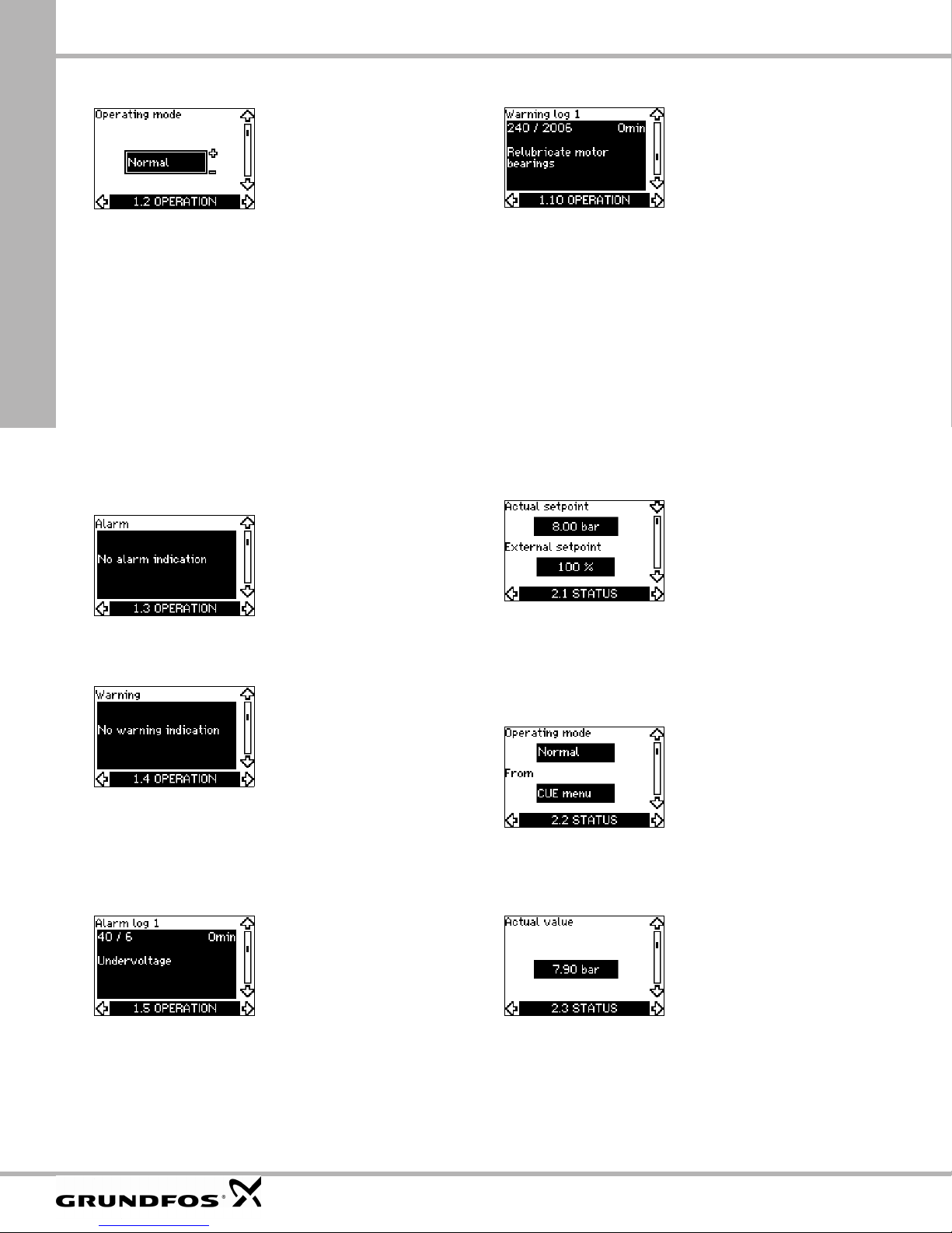
The tolerances are stated as a guide in % of the maximum value s
Grundfos CUE
17.5.2 Operating mode (1.2)
Set one of the follo wing op erat ing mo de s:
• Normal (duty)
• Stop
• Min.
• Max.
The operating mode s can be s et with out cha ngin g the setpoin t
setting.
17.5.3 Fault indications
Faults may result in tw o types of in dication : Ala rm or warni ng.
An "alarm" will activate an alarm in dication in CUE and ca use
the pump to chan ge oper atin g mode , typi cally t o stop . How ev er,
for some faults resultin g in alar m, the pu mp i s set to c ontinue
operating even if th ere is an alar m.
A "warning" will activate a warning indication in CUE, but the
pump will not change opera ting or control m ode.
Alarm (1.3)
Warning log (1.10-1.14)
In case of a "warning", the last fiv e war ning i ndica tions wi ll
appear in the warnin g log. "Warning log 1" s hows the late st fau lt,
"Warning log 2" shows the latest fau lt but on e, etc .
The display shows thr ee piec es of inf orm atio n:
• the warnin g ind ication
• the warnin g co de
• the number of minutes the pump has been connected to the
power supply after the warnin g occ urred.
17.6 Menu STATUS
The displays appea ring in this menu are status d isplays only. It is
not possible to chan ge or set value s.
The tolerance of the displayed value is stated under each display.
of the parameters.
10.6.1 Actual setpoint (2.1)
In case of an alar m, the caus e will app ear in the displa y.
See section 15.1 Warning and alarm list.
Warning (1.4)
In case of warning, the cause will a ppe ar in the dis play.
See section 15.1 Warning and alarm list.
17.5.4 Fault log
For both fault type s, a larm a nd wa rning , the CU E has a log
function.
Alarm log (1.5-1.9)
In case of an "alarm", the last five alarm indications will appear in
the alarm log. "Ala rm log 1" shows the la t es t alarm, "Alarm log 2"
shows the latest alar m but on e, etc .
The display shows thr ee piec es of inf orm atio n:
• the a lar m indication
• the a larm code
• the n umbe r of mi nut es the p um p has b een conne cte d to t he
power supply after the ala rm oc curr ed.
This display show s th e actual setp oint a nd the ex ter nal setp oint.
The actual setpoint is shown in u nits of fe edbac k se nsor.
The external setpoint is shown in a rang e of 0-10 0 %. If the
external setpoi nt influ ence is disac tivat ed, th e value 100 % is
shown. See section 13 .2 External se tpoi nt.
10.6.2 Operating mode (2.2)
This display shows the actual operating mode (Normal, Stop, Min.
or Max.). Furthermor e, it sh ow s w here th is op erat ing mo de was
selected (CUE menu, Bus, External or On/off button).
17.6.3 Actual value (2.3)
This display show s the ac tual value c ontr olled.
If no sensor is conn ected to the CU E, "– " will appe ar in t he
display.
46
Page 47

17.6.4 Measured value, sensor 1 (2.4)
17.6.9 Lubrication status of motor bearings (2.9)
This display show s the ac tual value m easu red by sens or 1
connected to ter minal 5 4.
If no sensor is connected to the CUE , "–" will appe ar in the
display.
17.6.5 Measured value, sensor 2 (2.5)
This display is onl y show n if an MCB 114 sensor input module
has been installed.
This display show s the ac tual value m easu red by sens or 2
connected to an MCB 114.
If no sensor is connected to the CUE , "–" will appe ar in the
display.
17.6.6 Speed (2.6)
Tolera nc e: ± 5 %
This display shows the actual pump speed.
17.6.7
Input power and motor current (2.7)
This display s hows how many times the user has given the
lubricated informa tion and whe n to r eplace the m otor be ar ings.
When the motor bear ings have bee n relub ricate d, co nfirm th is
action in the INSTALLATION menu. See section
17.7.17 Confirming relubrication/replacement of motor bearings
(3.20). When relubrica tion i s conf irmed , the figur e in the ab ove
display will be increa se d by one.
17.6.10 Time until relubrication of motor bearings (2.10)
This display is only s hown if dis pl ay 2.11 is not shown.
This display show s whe n to re lubric ate the mot or bea rings .
The controller monitors the opera ting pat tern of the pum p and
calculates the per iod bet ween b earing re lubric atio ns. If the
operating pattern ch ang es, th e calc ulated t ime till relu brica tion
may change a s well.
The estimated time un til rel ubricat ion takes into acc ount if the
pump has bee n runni ng w ith re duce d sp ee d.
See section 17.7.17 Confirming relubrication/replacement of
motor bearings (3.20).
17.6.11 Time until replacement of motor bearings (2.11)
Grundfos CUE
Tolera nce: ± 10 %
This display show s the ac tual pump in put p ower in W or kW and
the actual motor cur rent in Am pere [A].
17.6.8 Operating hours and power consumption (2.8)
Tolera nc e: ± 2 %
This display shows the number of operating hours and the power
consumption. T he valu e of op erating hou rs is an ac cum ul ated
value and cannot be reset. The value of power consumption is an
accumulated va lue cal culat ed from the unit’s birth, and it canno t
be reset.
This display is only show n if dis play 2.10 is no t shown .
This display show s whe n to re place the m otor be ari ngs.
The controller monitors the opera ting pat tern of the pump and
calculates the per iod bet ween b earing re place ments.
The estimated time until replacement of motor bearings takes into
account if the p ump ha s been ru nning with reduc ed sp eed .
See section 17.7.17 Confirming relubrication/replacement of
motor bearings (3.20).
17.6.12 Temperature sensor 1 (2.12)
This display is only s hown if an MC B 114 sensor input mo dule
has been installed.
This display show s the m easur ing poi nt and the ac tua l value
measured by Pt100 /Pt1 000 tem peratu re sen sor 1 conne cted to
the MCB 114. The measuring point is selec ted i n displa y 3.21.
If no sensor is connected to the CUE, "–" will appear in the display.
47
Page 48

Note
Grundfos CUE
10.6.13 Temperature sensor 2 (2.13)
This display is onl y show n if an MCB 114 sensor input mo dule
has been installed.
This display show s the m easur ing poi nt and the a ctual va lue
measured by Pt100 /Pt1 000 t empe rature senso r 2 co nnect ed to
the MCB 114. The measuring point is selec ted in dis play 3.22.
If no sensor is connected to the CUE, "–" will appear in the display.
17.6.14 Flow rate (2.14)
This display is onl y show n if a flo wm eter ha s be en co nfigu red.
This display show s the ac tual value m easu red by a flow meter
connected to the d igital pulse in pu t (termi nal 3 3) or the ana log
input (terminal 5 4).
17.6.15 Accumulated flow (2.15)
17.7 Menu INSTALLATION
17.7.1 Control mode (3.1)
Select one of th e following control m od es:
• Open loop
• Const. press ure
• Const. diff. pressure
• Prop. diff . press ure
• Const. flow rate
• Const. temp erat ure
• Constant le ve l
• Const. other value.
If the pump is connected to a bus, the control
mode cannot be selected via the CUE.
See section 20.3 GENIbus signal.
17.7.2 Controller (3.2)
This display is onl y show n if a flo wm eter ha s be en co nfigu red.
This display show s the va lue of the a ccum ulat ed flo w and t he
specific energy fo r the trans fer of the pump ed li quid.
The flow measurement can be connected to the digital pulse input
(terminal 33) or th e analog inp ut (ter mina l 54).
17.6.16 Firmware version (2.16)
This display shows the version of the s
1
Configuration file (2.17)
7.6.17
This display s hows the config ur at ion file.
oftware.
The CUE has a factor y set ting of gain (K
However, if the factory setting is not the optimum setting, the gain
and the integral ti me can b e ch anged in the display.
• The gain (K
• The integral time (T
3600 s. If 3600 s is selected, the controller wil l function as
a P controller.
• Furtherm ore, it is pos sibl e to set t he con trol ler to i nver se
control, meaning th at if t he setpo int is incre ased , the sp eed
will be reduced. In the case of inv erse cont rol, th e gain ( K
must be set within the ran ge from – 0.1 to –20.
) can be set within the r ange fr om 0.1 t o 20.
p
) can be set within the ra nge fr om 0.1 to
i
) and integral time (Ti).
p
)
p
48
Page 49

The table below sh ows t he su gge ste d cont rolle r se tting s:
t
K
p
System/application
CUE
Heating
system
Cooling
1)
system
2)
0.2 0.5
p
SP, SP-G, SP-NE: 0.5 0.5
CUE
0.2 0.5
p
SP, SP-G, SP-NE: 0.5 0.5
CUE
Q
CUE
L
CUE
0.2 0.5
–2.5 100
0.5 –0.5 10 + 5L
t
L
2
1. Heating systems are sy stem s in w hich an inc reas e in pum p
performance will result in a rise in tem peratur e at th e se nsor.
2. Cooling systems are sy stem s in w hich a n incr ease in pump
T
i
performance will result in a drop in tempera ture at t he sen sor.
= Distance in [m] between pump and s en sor.
L
1
L
= Distance in [m] between heat excha nge r and s ensor.
2
How to set the PI controller
For most applicat ions , the fac tory s etting of th e contr oller
constants K
and Ti will ensure optimum pum p oper ation.
p
Grundfos CUE
However, in some applications an a dju stmen t of the cont rolle r
may be needed.
Proceed as follows :
1. Increase the gain (K
) until the motor be com es uns table.
p
Instability can be seen by obser ving if the meas ured valu e
starts to fluctuate. Furthermore, instability is audible as the
motor starts hunting up an d down .
As some systems, such as temperature controls, are slowreacting, it may be difficult to obser ve that the motor is
unstable.
2. Set the gain (K
) to half the value of the value which made the
p
motor unstable. This is the c orrect s etting of the ga in.
3. Reduce the integral tim e (T
) until the motor become s
i
unstable.
4. Set the integral time (T
) to twice the value which made the
i
motor unstable. This is the c orrect s etting of the in tegral t ime.
General rules of thumb:
• If the contr oller is too s low-r eact ing, inc reas e K
.
p
• If the contr oller is hun ting or uns table, dampe n the syste m by
reducing K
or increasing Ti.
p
17.7.3 External setpoint (3.3)
2
CUE
Δt
L
2
CUE
CUE
L
2
Δp
CUE
L
1
Δp
* T
= 100 seconds (factory setting).
i
0.5 10 + 5L
0.5 –0.5 30 + 5L2*
0.5 0.5*
L
< 5 m: 0. 5*
1
0.5
> 5 m: 3*
L
1
> 10 m: 5*
L
1
2
The input for extern al set point sign al (te rmin al 53) c an be s et to
the following types:
• Active
• Not act ive.
If Active is selected, the actual setpoint is influenced by the signal
connected to the external setpoint input. See section
20.2 External setpoint.
49
Page 50

Grundfos CUE
17.7.4 Signal relays 1 and 2 (3.4 and 3.5)
The CUE has two signal r elays . In the d isplay be low, select in
which operating s ituatio ns the s ignal re lay sh ould be acti vate d.
Signal relay 1 Signal relay 2
ady
• Ready
• Alarm
• Operation
• Pump r unning
• No t a ctive
• Warning
• Relubricate
Note
17.7.5 Buttons on the CUE (3.6)
.
For distinction between alarm and warning,
see section 17.5.3 Fault indications.
• Re
• Alarm
• Operation
• P ump r unning
• No t a ctive
• Warning
• Relubricate.
17.7.7 Pump number (3.8)
This display show s the G ENIbu s n umbe r. A number betw een 1
and 199 can be alloc ated to the p ump. I n the case of bus
communication, a number must be allocated to each pump.
The factory setting is "–".
17.7.8 Digital inputs 2, 3 and 4 (3.9 to 3.11)
The editing buttons (+, –, On/Off, OK) on the control panel can be
set to these value s:
• Active
• Not active.
When set to Not active (locked), the editing buttons do not
function. Set the buttons to Not active if the pump should be
controlled via an external control system.
Activate the butt ons b y pres sing the arro w up and arr ow dow n
buttons simultaneo usly fo r 3 sec onds .
17.7.6 Protocol (3.7)
This display show s the pr otoc ol sel ection f or the R S-48 5 po rt of
the CUE. The protoc ol can be set to the se va lues:
• GENIbus
• FC
• FC MC .
If GENIbus is selected, the communication is set according to the
Grundfos GENIb us standa rd. FC and FC MC is for s ervi ce
purpose only.
The digital inputs of the CUE ( termin al 19, 32 a nd 3 3) can
individually be se t to differe nt func tion s.
Select one of the following functions:
• Min. (min. curve)
• Max. (max. curve)
• Ext. fault (external fault)
• Flow sw it ch
• Alarm res et
• Dry run ning (f rom extern al sen sor)
• Accumulated flow (pul se flow, only terminal 3 3)
• Not active.
The selected function is active when the digital input is activated
(closed contact). S
Min.
When the input is activated, the pump w ill oper ate accor ding to
the min. curve.
Max.
When the input is activated, the pump w ill oper ate accor ding to
the max. curve.
Ext. fault
When the input is act ivated, a timer will be s tarted. If the input is
activated for more than 5 se conds, an e xtern al fault will be
indicated. If the input is deactivate d, the fau lt con ditio n will c ea se
and the pump ca n on ly be re start ed m anually by re se tting t he
fault indication.
Flow switch
When this function is select ed, the pu mp will be stopp ed whe n a
connected flow swi tch d etects lo w flow.
It is only possible to use this fun ctio n if the p ump is co nnec ted to
a pressure sensor or a level sensor, and the stop function is
activated. See sections 17.7.10 and 17.7.11.
Alarm reset
When the input has been activated, the alarm is reset if the cause
of the alarm no longer exists.
ee also section 20.1 Digital inputs.
50
Page 51

Dry running
When this function is sele cted , lac k of inlet press ure or wate r
shortage can be detected. This req u ir es th e us e of an accessory,
such as:
• a Grun dfos Liq tec
• a press ure s witch ins talled on t he suct ion sid e of a p ump
• a float swit ch ins talled on the suc tion s ide of a pu m p.
When lack of inlet pr essur e or wat er s hortage ( D ry runn ing) is
detected, the pump will be s topped. Th e pu mp canno t restart as
long as the input is activa ted.
Restarts may be delaye d by up to 30 mi nutes , dep ending on the
pump family.
Accumulated flow
When this function is set for digital input 4 and a pu lse s ensor is
connected to ter minal 3 3, the a ccum ulat ed flo w can be
measured.
17.7.9 Digital flow input (3.12)
This display ap pears only if a flo wme te r has b een co nfigu re d in
display 3.11.
The display is use d for settin g the volum e for ev ery p uls e for the
function Accu mulate d flow with a pulse s enso r conn ected to
terminal 33.
Setting range:
• 0-26 5 gal/puls e (0- 1000 lit re/pu ls e).
The volume can be set in the unit selected in the start-up guide.
17.7.10
Constant pressure with stop function (3.13)
Settings
The stop function can b e set to these v alues :
• Active
• No t ac tive.
The on/off band can be set to thes e valu es:
• Δ H is factory-set to 10 % of actual setpoint.
• Δ H can be set within th e range from 5 % to 30 % of the act ual
setpoint.
Operating conditions for the stop function
It is only possible t o use th e sto p funct ion if the sys tem
incorporates a pr essur e se nsor, a check valve and a dia ph ragm
tank.
Descriptions
The stop function is used f or c hangin g be tween on /off oper atio n
at low flow and contin uous ope ratio n at hi gh flow.
®
dry-running swit ch
On/off operation
Continuous ope ration
Stop pressure
Start pressure
Fig. 50 Constant pressur e wi th sto p funct ion. Difference
Low flow can be detec ted in two differen t ways:
1. A built-in "low-flow detection function " which f unc tions if th e
digital input is not set up fo r flo w swit ch.
2. A flow switch connected to th e digital inpu t.
1. Low-flow detection function
The pump will chec k the flow r egular ly by reduc ing th e spee d for
a short time. If there is no or only a small change in pressure, this
means that there is low flow.
The speed will be incr ease d un til the s top pre ssur e (ac tual
setpoint + 0.5 x ΔH) is reached and the pump will stop after a few
seconds. The pum p will re start at the la test whe n the pressur e
has fallen to the start pressur e (ac tual set point – 0.5 x Δ H).
If the flow in the off period is high er th an the l ow-flow lim it, th e
pump will restart before the press ure ha s fallen to the start
pressure.
When restarting, the pump will react in the followin g way:
1. If the flow is higher than the low-flow limit, the pump will return
to continuous operat ion at cons tant pre ssure.
2. If the flow is lower than the low-flow limit, the pump will
continue in start/sto p oper ation . It will co ntinu e in start/stop
operation until the flow is higher than the low-flow limit. When
the flow is higher than the low-flow limit, the pump will return to
continuous operat ion.
2. Low-flow detection with flow switch
When the digital input is ac tivated becau se ther e is low- flow, the
speed will be increased until the stop pres sure (actua l setpoin t
+ 0.5 x ΔH) is reached, and the pump will stop. When the
pressure has fallen to start pressu re, the pu mp will s tart again.
If the re is still no flo w, the pump will reach the sto p pres sure and
stop. If there is flow, the pump wi ll contin ue o peratin g ac cord ing
to the setpo i nt.
Caution
ΔH
between start and stop pre ssures (ΔH)
The check valve mus t alwa ys be inst alled b efore
the pressure sensor. See figs 51 and 52 .
If a flow switch is used to detect low flow, the
switch must be inst all ed o n t h e sy stem side after
the diaphragm tank.
Grundfos CUE
TM03 8477 1607
51
Page 52

Check valve
Diaphragm tank
Grundfos CUE
Diaphragm tank
Pressure sens or
Pump
Fig. 51 Position of the c heck va lve an d pres su re se nsor in
Fig. 52 Position of the c heck va lve an d pres su re se nsor in
Diaphragm tank
The stop function requires a diaphragm tank of a certain minimum
size. The tank must b e installed a s clos e as po ssib le after t he
pump and the prec harge pressu re mus t be 0.7 x actu al set point .
Recommended diaphr agm ta nk size:
If a diaphragm tank of t he abo ve size is ins talled in the s ystem ,
the factory setting of ΔH is the corre ct setting.
If the tank installed is too small, the pump w ill start and stop too
often. This can be rem edied b y in crea sing Δ H.
17.7.11 Constant level with stop function (3.13)
system with suction lift operation
Pressure sensor
Pump Check valve
system with positiv e inlet pressu re
Rated flow rate of pump
[gpm]
0-26 2
27-105 4.4
106-176 14
177-308 34
309-440 62
Typical diaphragm tank size
[gallons]
A built-in low-flow de tection fun ction wi ll auto matica lly me asur e
and store the power consu mption at ap prox. 5 0 % and 8 5 % of
the rated speed.
If Active is selected, proceed as follows:
1. Close the isolating val ve to cr eate a no-f low co ndit ion.
2. Press OK to start the auto-t uning.
Operating conditions for the stop function
It is only possible to us e the cons tant leve l sto p func tion if the
system incorporates a level sensor, and all valves can be closed.
TM03 8582 1907TM03 8583 1907
Description
The stop function is used f or c hangin g be tween on /off oper atio n
at low flow and contin uou s oper atio n at hi gh flow.
Start level
Stop level
Fig. 53 Constant leve l with st op func tion . Differe nce be twee n
Low flow can be detec ted in two differen t ways:
1. With the built-in low-fl ow det ectio n fun ctio n.
2. With a flow switch connected to a dig ital input.
1. Low-flow detection function
The built-in low-flo w de tecti on is ba sed on the m easu reme nt of
speed and power.
When low flow is detected, the pump will stop. When the level has
reached the start level, the pump will start again. If there is still no
flow, the pump will reach the stop level and stop. If there is flow,
the pump will continue ope rating a ccor ding to the setpoin t.
2. Low-flow detection with flow switch
When the digital input is activated because of low flow, the speed
will be increased until the stop level (actual setpoint – 0.5 x ΔH) is
reached, and th e pu m p will stop. When the lev el has reached the
start level, the pump will start again. If there is still no flow, the
pump will reach the s top lev el and stop. If there is flow, the pump
will continue operating acc ording to the s etpoint.
17.7.12 Sensor 1 (3.15)
ΔH
start and stop levels (ΔH)
TM03 9099 3307
Settings
The stop function can b e set to these v alues :
• Active
• No t ac tive.
The on/off band can be set to thes e valu es:
• Δ H is factory-set to 10 % of actual setpoint.
• Δ H can be set within the range from 5 % to 30 % of actual
setpoint.
52
Setting of sensor 1 connected to terminal 54. This is the feedback
sensor.
Select among the foll owing v alues :
• Sensor ou tput signa l:
0-20 mA
4-20 mA.
• Unit o f measurement of sensor:
bar, mbar, m, kPa, psi, ft, m
• Sensor m easur ing ra nge .
3
/h, m3/s, l/s, gpm, °C, °F, %.
Page 53

17.7.13 Sensor 2 (3.16)
Setting of sensor 2 con nect ed to an M CB 114 sensor input
module.
Select among the foll owing v alues :
• Sensor output signa l:
0-20 mA
4-20 mA.
• Unit of meas urem ent of se nsor:
bar, mbar, m, k Pa, psi, ft, m
• Sensor meas uring range :
0-100 %.
17.7.14 Duty/standby (3.17)
Settings
The duty/standby func tion can be se t to th ese value s:
• Active
• No t ac tive.
Activate the duty/ standby fun ctio n as f ollo ws:
1. Connect one of the pu mps to the m ains s upply.
Set the duty/standby fun ctio n to No t a ctive.
Make the necessary s etting s in me nu OPER ATION and
INSTALLATION.
2. Set the operating mode to Stop in menu OPERATION.
3. Connect the other pu mp t o the mains su ppl y.
Make the necessary s etting s in me nu OPER ATION and
INSTALLATION.
Set the duty/standby fun ctio n to Active.
The running pump will s earch for the other p ump an d
automatically set the duty/standby function of this pump to Active.
If it cannot find the other pump, a fault will b e indicated.
3
/h, m3/s, l/s, gpm, °C, °F, %.
Grundfos CUE
The two pumps must be connected electrically
Note
The duty/standby func tion applies to tw o pum ps con nected in
parallel and controlle d vi a GENIbu s. E ach p ump must be
connected to its own CUE an d sens or.
The primary targets of the fun ctio n is the f ollowin g:
• To start the standby pump if the duty pum p is st oppe d du e to
an alarm.
• To alternate the pumps at least eve ry 24 h ours.
via the GENIbus, and nothing else must be
connected on the GENIbus.
53
Page 54

Nominal speed Max. s peed
Min. speed
Grundfos CUE
17.7.15 Operating range (3.18)
How to set the operating range:
• Set the m in . speed w ithin the ra nge f rom a pump -depe ndent
min. speed to the adju sted m ax. speed . The f actor y set ting
depends on the pump fam ily.
• Set the max. speed within the range from adjusted min. speed
to the pump-depen dent m axim um sp eed . The fac tor y sett ing
will be equal to 100 %, i.e. the sp eed stated on the p ump
nameplate.
Pump-depende nt spee d ra nge
Min.
Actual speed ra nge
Min. speed, adjuste d
The area between the min. and m ax. speed is th e actual
operating range of the pump.
The operating ra nge ca n be chang ed by the us er within the
pump-depende nt sp eed range .
For some pump families, oversynchronous operation (max. speed
above 100 %) will be possible. This requires an oversize motor to
deliver the shaft power r equir ed by the pump during
oversynchrono us opera tion.
Speed [%]
Max.
100 %
Max. speed, adjus ted
Fig. 54 Setting of the min. and max. curves in % of maximum performance
10.7.16 Motor bearing monitoring (3.19)
The motor bearing monitoring function can be set to these values:
• Active
• No t a ctive.
When the function is set to Active, the CUE will give a warn ing
when the motor bearings are due to be relubricated or replaced.
Description
The motor bearing m onit oring func tion is used to give a n
indication when it is tim e to rel ubri cate or replac e the motor
bearings. See dis play 2 .10 an d 2.11.
The warning indication and the estimated time take into account if
the pump has been running with reduced speed. Furthermore, the
bearing temperature is included in the calculation if temperature
sensors are installed a nd con ne cted to an MC B 114 sensor input
module.
The counter will continue counting even if the
Note
function is switched to Not active, but a warning
will not be given when it is time for relubrication.
10.7.17 Confirming relubrication/replacement of motor
bearings (3.20)
This function can be s et to the se va lues:
• Relubricated
• Replaced
• Nothing done.
When the motor be arings have bee n relub ricat ed or replac ed,
confirm this action in the a bove d isp lay by pres sing "OK ".
Note
Relubricated
When the warning Relubric ate mot or be arings ha s been
confirmed,
• the counter is set to 0.
• the numbe r of relu bri cati ons is inc reas ed b y 1.
When the number of relub ricatio ns has re ache d the per miss ible
number, the warning Replac e motor bearin gs app ears in the
display.
Relubricated cannot be selected for a period of
time after confirming relubrication.
TM04 3581 4608
54
Page 55

Replaced
Time
When the warning Replace m oto r bear ing s ha s b een co nfir med,
• the cou nter is set to 0 .
• the num be r of relu brica tions is se t to 0.
• the num be r of bear ing ch ang es is in crea sed by 1.
17.7.18 Temperature sensor 1 (3.21)
17.7.21 Ramps (3.24)
This display is onl y show n if an MCB 114 sensor input mo dule
has been installed.
Select the functio n of a P t100/ Pt100 0 tem peratu re sensor 1
connected to an MCB 114:
• D-en d bear ing
• ND-e nd bear ing
• Other liq. temp. 1
• Other liq. temp. 2
• Motor windin g
• Pumpe d liq. tem p.
• Ambien t temp.
• Not active.
17.7.19 Temperature sensor 2 (3.22)
This display is onl y show n if an MCB 114 sensor input mo dule
has been installed.
Select the functio n of a P t100/ Pt100 0 tem peratu re sensor 2
connected to an MCB 114:
• D-en d bear ing
• ND-e nd bear ing
• Other liq. temp. 1
• Other liq. temp. 2
• Motor windin g
• Pumpe d liq. tem p.
• Ambien t temp.
• Not active.
17.7.20 Standstill heating (3.23)
Set the time for e ac h of the two r amps, ramp -u p and ra m p-dow n:
• Factory s etting :
Depending on power size.
• The ran ge of the ramp parameter:
1-3600 s.
The ramp-up time is the acceleration time from 0 rpm to the rated
motor speed. Choose a ramp-up time such that the output current
does not exceed t he ma xi mu m cu rrent lim it f or the C UE .
The ramp-down tim e is the d ecele ratio n time f rom rate d mot or
speed to 0 rpm. Choo se a ram p-dow n tim e such t hat no
overvoltage arises an d suc h that t he gen erat ed cu rrent does not
exceed the maximum current limit for the CUE.
Speed
Rated
Maximum
Minimum
Initial ramp Final ramp
Ramp-up Ramp-down
Fig. 55 Ramp-up and r amp- down, disp lay 3.24
Setting by means of PC Tool E-products
18.
Special setup requirements differing from t he se ttings availa ble
via the CUE require the use of Grundfos PC Tool E-products. This
again requires th e as sistance of a Grundfo s se rv ice technician or
engineer. Contact your local Grundfos com pany f or more
information.
Grundfos CUE
TM03 9439 0908
The standstill heat ing func tion c an be s et to t hese val ues :
• Active
• No t ac tive.
When the function is set to Active and the p um p is sto ppe d by a
stop command, a c urre nt wil l be appli ed to th e m otor win ding s.
The standstill heat ing func tion p re-he ats the m otor t o avoid
condensation.
55
Page 56

Grundfos CUE
Priority of settings
19.
The On/Off button has the highest priority. In "off"
On/
Off
condition, pump operation is not possible.
The CUE can be cont rolled in vari ous ways at the s ame time .
If t wo or m ore o per ating m od es are active at the s ame t ime,
the operating mode with the high est pri ori ty will be in forc e.
19.1 Control without bus signal, local operating mode
Priority CUE menu External signal
1Stop
2Max.
3 Stop
4
5 Min. Min.
6 Normal Normal
Example: If an external signal has acti vated the op erating m ode
Max., it will only be possible to stop the pump.
Max.
19.2 Control with bus signal, remote-controlled
operating mode
Priority CUE menu External signal Bus signal
1 Stop
2 Max.
3 Stop Stop
4
5
6
Example: If the bus signal has activated t he ope ra ting mod e
Max., it will only be possible to stop the pump.
External control signals
20.
Max.
Min.
Normal
20.1 Digital inputs
The overview sho ws funct ions in co nnectio n with cl os ed con tact.
Terminal Type Function
18 DI 1 • Start/stop of pump
• Min. (min. curve)
• Max. (max. curve)
• Ext. fault (external fault)
19 DI 2
32 DI 3
• Flow switch
• Alarm res et
• Dry runn ing (fro m exte rnal s ensor )
• Not activ e.
• Min. (min. curve)
• Max. (max. curve)
• Ext. fault (external fault)
• Flow switch
• Alarm res et
• Dry runn ing (fro m exte rnal s ensor )
• Not activ e.
Terminal Type Function
• Min. (min. curve)
• Max. (max. curve)
• Ext. fault (external fault)
33 DI 4
The same function m us t not be s ele cted fo r more t han on e inp ut.
See fig. 21.
• Flow switch
• Alarm reset
• Dr y running (f rom external s ens or )
• Acc umula ted flo w (p ulse flo w)
• Not activ e.
20.2 External setpoint
Terminal Type Function
53 AI 1 • External setpoint (0-10 V)
The setpoint can b e remo te- set by c onnec ting an anal og s ignal
transmitter to the s etpo int in put (te rmin al 53).
Open loop
In control mode O pen loop (c onsta nt cu rve) , the actual setpoint
can be set externa lly w ithin the rang e fro m the m in. cu rve to th e
setpoint set via the CUE m enu. See fi g. 56.
Setpoint
Max. curve
Setpoint, CUE menu
Actual
Actual setpoint
Min. curve
0 10 V
Ext. setpoint signal
Fig. 56 Relation bet ween t he ac tual set point and the ex ternal
setpoint signal in control m o de Open lo op
setpoint
range
TM03 8856 2607
56
Page 57

Closed loop
In all other contro l modes , ex cept pr opor tiona l differentia l
pressure, the actu al setpo int c an b e set ex ternal ly wi th in the
range from the lowe r value of the s en sor mea surin g rang e
(sensor min.) to the set point se t via the CU E me nu. Se e fig. 57.
Setpoint
Sensor max.
Setpoint, CUE menu
Actual
Actual setpoint
Sensor min.
0 10 V
Ext. setpoint signal
Fig. 57 Relation bet ween t he ac tual set point and the ex ternal
Example: At a sensor min. value of 0 bar, a setpoint set v ia the
CUE menu of 3 bar a nd an ex ter nal setp oin t of 80 % , the ac tual
setpoint will be as follows:
Actual setpoin t =
setpoint signal in con trol mo de C ontrolle d
(setpoint set via the C UE m enu – s ensor min. )
x % external setpoint sign al + sens or m in.
= (3 – 0) x 80 % + 0
= 2.4 bar.
setpoint
range
20.3 GENIbus signal
The CUE suppo rts se rial co m munic atio n via an RS -485 in pu t.
The communica tion is c arried out a ccor ding to t he G rundfos
GENIbus protocol and ena bles c onnec tion to a buildin g
management sy ste m or an othe r ext erna l co ntrol sy st em.
Operating parame ters , su ch as set point and ope ra ting mod e c an
be remote-set v ia the bus signal. At the same time, the pump can
provide status infor mat ion ab out im po rtant param ete rs, such as
actual value of co ntrol para met er, input power and fault
indications.
Contact Grundfos for furthe r details .
Note
If a bus signal is used, the number of settings
available via the CUE will be reduced.
20.4 Other bus standards
Grundfos offers variou s b us sol ution s wit h com munic atio n
according to other standa rds.
Contact Grundfos for furthe r details .
Maintenance and service
21.
TM03 8856 2607
21.1 Cleaning the CUE
Keep the cooling f ins and fan b lades clean t o ens ure su fficient
cooling of the CUE.
21.2 Service parts and service kits
For further info rmat ion on se rvic e parts and serv ice ki ts, visit
www.grundfos.com > In t ernational website > WebCAPS.
Grundfos CUE
Proportional differential pressure
In control mode Proportiona l diff erentia l pres sure , th e actual
setpoint can be set exter nally w ithin the ra ng e from 2 5 % of
maximum head to the setpoint set via the CUE m enu. See fig. 58.
Setpoint
90 % of max . head
Setpoint, CUE menu
Actual
Actual setpoint
25 % of max. head
0 10 V
Ext. setpoint signal
Fig. 58 Relation bet ween t he ac tual set point and the ex ternal
setpoint signal in control mode Proportional differential
pressure
Example: At a maximum head of 12 metres, a setpoint of
6 metres set via the CUE me nu an d an external setpoint of 40 %,
the actual setpoint will be as follows :
Actual setpoin t =
(setpoint, CUE men u – 25 % o f maxim um
head) x % external se tpoint signa l + 25 % of
maximum head
= (6 – 12 x 25 %) x 40 % + 12/4
= 4.2 m.
setpoint
range
TM03 8856 2607
57
Page 58

Grundfos CUE
Troubleshooting
22.
22.1 Warning and alarm list
Status
Code and display text
Warning
Too high le akage
1
current
2 Mains phase failure
3 External fault
16 Othe r fault
30 Replace motor bearings z
32 Overvoltage
40 Undervoltage
48 Overload
49 Overload
55 Overload
57 Dry runn ing
Too high C UE
64
temperature
Too high m oto r
70
temperature
Communication faul t,
77
duty/standby
89 Sensor 1 outside r ange
Temperat ure sen sor 1
91
outside range
93 Sensor 2 outside r ange z
Setpoint signal outside
96
range
Too high b earing
148
temperature
Too high b earing
149
temperature
155 Inrush fault
Temperat ure sen sor 2
175
outside range
Relubricate motor
240
bearings
241 Motor phase failure
242 AMA
1)
In case of an alarm, the CUE wi ll chang e the opera ting m ode
depending on the pum p type.
2)
AMA, Automatic Motor Adaptation. Not active in the present
software.
3)
Warning is reset in display 3.20.
2)
did not succeed z – Man.
z Stop Aut.
z Stop Man.
z Stop Aut.
z
z Stop Aut.
z
z Stop Aut.
z Stop Aut.
z Stop Aut.
z
z Stop Aut.
z Stop Aut.
z Stop Aut.
z Stop Aut.
z
z
z
z
z
z Stop Aut.
z
z Stop Aut.
z Stop Aut.
z
z
z
z Stop Aut.
Operat-
ing mode
Alarm
Locked alarm
z Stop Man.
z Stop Man.
– Man.
– Aut.
– Aut.
z Stop Man.
– Aut.
– Aut.
1)
– Aut.
– Aut.
1)
– Aut.
– Aut.
– Aut.
– Man.
– Aut.
Reset-
ting
Aut.
Aut.
22.2 Resetting of alarms
In case of fault or ma lfun ctio n of the CUE, ch ec k the ala rm lis t in
menu OPERATION. The latest five alarms and latest five
warnings can be found in the log men us.
Contact a Grundfo s tec hni cian if an ala rm oc curs re peat edly.
22.2.1 Warning
The CUE will continue the oper ation as long as the w arning is
active. The warni ng rem ains a ctive u ntil t he cau se no longer
exists. Some warni ngs m ay sw itch to alarm condi tion.
22.2.2 Alarm
In case of an alarm, the CUE wi ll sto p the p ump or c han ge the
operating mode de pendin g on the ala rm t ype a nd pum p type.
See section 15.1 Warning and alarm list.
Pump operation will be resumed when the cause of the alarm has
been remedied an d the alarm has be en re set.
3)
Resetting an alarm manually
• Press OK in the al arm di splay.
• Press On/Off twice.
• Activate a digital input DI 2-DI 4 s et to Alarm reset or the
digital input DI 1 (Start/stop).
If it is not possibl e to rese t an a larm, the rea son may be that the
fault has not been re m edied, or that t he alar m has been lo cke d.
15.2.3 Locked alarm
In case of a locked al arm, the CUE wi ll stop t he pum p and
become locked. Pump opera tion c anno t be re sum ed until t he
cause of the locked alarm has be en rem edied and the al arm h as
been reset.
Resetting a locked alarm
• Switch off the powe r supply to the C UE for a pprox .
30 seconds. Switch on the po wer su pply, and press OK in the
alarm display to reset the alarm.
22.3 Indicator lights
The table show the functio n of the ind icator li ghts.
Indicator
light
On (green)
Off (orange)
Alarm (red) In dicat es an alarm or a warni ng.
Function
The pump is runnin g or ha s be en stop ped by
a stop function.
If flashing, the pump h as bee n sto pped b y the
user (CUE menu) , exte rnal s tart/stop o r bus .
The pump has been stop pe d with th e On /Off
button.
22.4 Signal relays
The table show the functio n of the sig nal relay s.
Type Function
3)
Relay 1
Relay 2
See also fig. 30.
• Ready
• Alarm
• Operation
• Ready
• Alarm
• Operation
• Pump r unning
• Warning
• Relubricate.
• Pump r unning
• Warning
• Relubricate.
58
Page 59
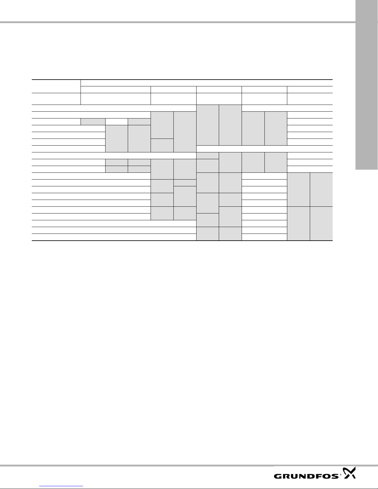
Technical data
23.
23.1 Enclosure
The individual CUE cabine t siz es ar e charac ter ised by the ir
enclosures. The table sho ws t he rela tionship of en closu re cla ss
and enclosure t y pe.
Example:
Read from the name plate:
• Supply v ol tage = 3 x 3 80-500 V.
• Typical shaft power = 1.5 kW.
• Enclosur e clas s = IP20.
The table shows that t he CUE enclo sure is A2.
Typical shaft
power P2
[kW] [HP]
0.55 0.75
0.75 1
1.1 1.5
1.5 2
2.2 3
34
3.7 5
45
7.5 10
11 15
15 20
18.5 25
30 40
37 50
45 60
55 75
75 100
90 125
Enclosure class and type
1 x 200-240 V 3 x 200-240 V 3 x 380-500 V 3 x 525-600 V 3 x 525-690 V
IP20
NEMA0
A3 A5
IP21
NEMA1
B1 B1
B2 B2
IP55
NEMA12
IP20
NEMA0
A2
A3
B3 B1
B4
C3
C4 C2
IP55
NEMA12
A5
B2
C122 30
IP20
NEMA0
A2 A5
A2
A3
B3 B1
B4
C3
C4 C2
IP55
NEMA12
A5 A3 A55.5 7.5 B1 B1
B2
C1
IP20
NEMA0
A3 A5
IP55
NEMA12
IP21
NEMA1
B2 B2
C2 C2
IP55
NEMA12
Grundfos CUE
59
Page 60

Grundfos CUE
23.2 Main dimensions and weight
B4, C3, C4
TM03 9000 2807
Fig. 59 Enclosures A2 and A3 Fig. 60 Enclosures A5, B1, B2, B3, B4, C1, C2, C3 and C4
Enclosure
A2 10.6 10.1 3.5 2.8 8.1 8.6 0.31 0.43 0.22 0.35 10.8
with IP21/NEMA1 option 14.8 13.8 3.5 2.8 8.1 8.6 0.31 0.43 0.22 0.35 11.7
A3 10.6 10.1 5.1 4.3 8.1 8.6 0.31 0.43 0.22 0.35 14.6
with IP21/NEMA1 option 14.8 13.8 5.1 4.3 8.1 8.6 0.31 0.43 0.22 0.35 15.4
A5 16.5 15.8 9.5 8.5 7.9 7.9 0.32 0.47 0.26 0.35 30.9
B1 18.9 17.9 9.5 8.3 10.2 10.2 0.47 0.75 0.35 0.35 50.7
B2 25.6 24.6 9.5 8.3 10.2 10.2 0.47 0.75 0.35 0.35 59.5
B3 15.7 15.0 6.5 5.5 9.8 10.3 0.31 0.47 0.27 0.31 26.5
with IP21/NEMA1 option 18.7 – 6.5 – 9.8 10.3 0.31 0.47 0.27 0.31 –
B4 20.5 19.5 9.1 7.9 9.5 9.5 – – 0.33 0.59 51.8
with IP21/NEMA1 option 26.4 – 10.0 – 9.7 9.7 – – 0.33 0.59 –
C1 26.8 25.5 12.1 10.7 12.2 12.2 0.47 0.75 0.35 0.39 99.2
C2 30.3 29.1 14.6 13.1 13.2 13.2 0.47 0.75 0.35 0.39 143
C3 21.7 20.5 12.1 10.6 13.1 13.1 – – 0.33 0.67 77.2
with IP21/NEMA1 option 29.7 – 13.0 – 13.3 13.3 – – 0.33 0.67 –
C4 26.0 24.8 14.6 13.0 13.1 13.1 – – 0.33 0.67 110
with IP21/NEMA1 option 37.4 – 15.4 – 13.3 13.3 – – 0.33 0.67 –
1)
The dimensions are max imum height , width an d dept h. Di mens ions a re wit hout opt ions .
Height [in]
AaBbC
1)
Width [in]
1)
Depth [in]
1)
2)
C
Screw holes [in]
c ∅d ∅ef
Weight [lb]
23.3 Surroundings 23.4 Terminal tightening torques
Relative humidity 5-95 % RH
Ambient temperat ure Max. 122 °F
Average ambient tempe ratu re over 2 4 hour s Max. 113 °F
Minimum ambient tem pera ture at full
operation
Minimum ambient tempe ra ture at reduc ed
operation
Temp eratur e durin g stora ge and
transportation
–13 to 149 °F
32 °F
14 °F
Storage duration Max. 6 month s
Maximum altitude abo ve se a level witho ut
performance re du ctio n
Maximum alt itude above se a level with
performance re du ctio n
Note
The CUE comes in a packaging which is not
suitable for outdoor storage.
3280 ft
9840 ft
Enclosure
type
Mains Motor Ground Relay
A2 1.3 1.3 2.2 0.4
A3 1.3 1.3 2.2 0.4
A5 1.3 1.3 2.2 0.4
B1 1.3 1.3 2.2 0.4
B2 3.3 3.3 2.2 0.4
B3 1.3 1.3 2.2 0.4
B4 3.3 3.3 2.2 0.4
C1 7.4 7.4 2.2 0.4
C2 10.3
C3 7.4 7.4 2.2 0.4
C4 10.3
1)
Conductor gauge siz e ≤ 4/0 AWG.
2)
Conductor gauge siz e ≥ 4/0 AWG.
Tightening torque [lb-ft]
1)
/ 17.72)10.31)/ 17.7
1)
/ 17.72)10.31)/ 17.7
2)
2)
2.2 0.4
2.2 0.4
TM03 9002 2807
60
Page 61

23.5 Cable length
Maximum leng th, scre ened m oto r cable 500 ft
Maximum leng th, uns creene d m otor ca ble 1000 ft
Maximum leng th, sig nal cab le 1000 ft
23.6 Fuses and cable gauge size
Warning
Always comply with national and local
regulations as to cable gauge sizes.
23.6.1 Cable gauge size to signal terminals
Maximum cab le gaug e si ze to sig nal
terminals, rigid conductor
Maximum cab le gaug e si ze to sig nal
terminals, flexi ble conductor
Minimum cable gau ge s ize to s ignal
terminals
23.6.2 Non-UL fuses and conductor cross-section
(gauge size) to mains and motor
Typical shaft
power P2
[kW] [A]
1 x 200-240 V
1.1 20 gG 4
1.5 30 gG 10
2.2 40 gG 10
340gG10
3.7 60 gG 10
5.5 80 gG 10
7.5 100 gG 35
3 x 200-240 V
0.75 10 gG 4
1.1 20 gG 4
1.5 20 gG 4
2.2 20 gG 4
332gG4
3.7 32 gG 4
5.5 63 gG 10
7.5 63 gG 10
11 63 gG 10
15 80 gG 35
18.5 125 gG 50
22 125 gG 50
30 160 gG 50
37 200 aR 95
45 250 aR 120
3 x 380-500 V
0.55 10 gG 4
0.75 10 gG 4
1.1 10 gG 4
1.5 10 gG 4
2.2 20 gG 4
320gG4
420gG4
5.5 32 gG 4
7.5 32 gG 4
11 63 gG 10
15 63 gG 10
Maximum
fuse size
Fuse
Maximum conductor
type
cross-section
[mm
2
]
14 AW G
18 AW G
20 AW G
1)
Typical shaft
power P2
[kW] [A]
18.5 63 gG 10
22 63 gG 35
30 80 gG 35
37 100 gG 50
45 125 gG 50
55 160 gG 50
75 250 aR 95
90 250 aR 120
3 x 525-600 V
0.75 10 gG 4
1.1 10 gG 4
1.5 10 gG 4
2.2 20 gG 4
320gG4
420gG4
5.5 32 gG 4
7.5 32 gG 4
3 x 525-690 V
11 63 gG 35
15 63 gG 35
18.5 63 gG 35
22 63 gG 35
30 63 gG 35
37 80 gG 95
45 100 gG 95
55 125 gG 95
75 160 gG 95
90 160 gG 95
1)
Screened motor ca ble, u nscr eened su pply c abl e.
Maximum
fuse size
Maximum conductor
Fuse
type
cross-section
[mm
AWG, see section 16.6.3.
1)
2
]
Grundfos CUE
61
Page 62

Grundfos CUE
23.6.3 UL fuses and conductor cross-section (gauge size) to mains and motor
Typical shaft
power P2
[kW]
1 x 200-240 V
1.1 KTN-R20 – – – – – – 10
1.5KTN-R30––––– – 7
2.2KTN-R40––––– – 7
3KTN-R40––––– – 7
3.7KTN-R60––––– – 7
5.5––––– – – 7
7.5––––– – – 2
3 x 200-240 V
0.75 KTN-R10 JKS-10 JJN-10 5017906-010 KTN-R10 ATM-R10 A2K-10R 10
1.1 KTN-R20 JKS-20 JJN-20 5017906-020 KTN-R20 ATM-R20 A2K-20R 10
1.5 KTN-R20 JKS-20 JJN-20 5017906-020 KTN-R20 ATM-R20 A2K-20R 10
2.2 KTN-R20 JKS-20 JJN-20 5017906-020 KTN-R20 ATM-R20 A2K-20R 10
3 KTN-R30 JKS-30 JJN-30 5012406-032 KTN-R30 ATM-R30 A2K-30R 10
3.7 KTN-R30 JKS-30 JJN-30 5012406-032 KTN-R30 ATM-R30 A2K-30R 10
5.5 KTN-R50 JKS-50 JJN-50 5012406-050 KLN-R50 – A2K-50R 7
7.5 KTN-R50 JKS-60 JJN-60 5012406-050 KLN-R60 – A2K-50R 7
11 KTN-R60 JKS-60 JJN-60 5014006-063 KLN-R60 A2K-60R A2K-60R 7
15 KTN-R80 JKS-80 JJN-80 5014006-080 KLN-R80 A2K-80R A2K-80R 2
18.5 KTN-R125 JKS-150 JJN-125 2028220-125 KLN-R125 A2K-125R A2K-125R 1/0
22 KTN-R125 JKS-150 JJN-125 2028220-125 KLN-R125 A2K-125R A2K-125R 1/0
30 FWX-150 – – 2028220-150 L25S-150 A25X-150 A25X-150 1/0
37 FWX-200 – – 2028220-200 L25S-200 A25X-200 A25X-200 4/0
45 FWX-250 – – 2028220-250 L25S-250 A25X-250 A25X-250 250 MCM
3 x 380-500 V
0.55 KTS-R10 JKS-10 JJS-10 5017906-010 KTN-R10 ATM-R10 A2K-10R 10
0.75 KTS-R10 JKS-10 JJS-10 5017906-010 KTN-R10 ATM-R10 A2K-10R 10
1.1 KTS-R10 JKS-10 JJS-10 5017906-010 KTN-R10 ATM-R10 A2K-10R 10
1.5 KTS-R10 JKS-10 JJS-10 5017906-010 KTN-R10 ATM-R10 A2K-10R 10
2.2 KTS-R20 JKS-20 JJS-20 5017906-020 KTN-R20 ATM-R20 A2K-20R 10
3 KTS-R20 JKS-20 JJS-20 5017906-020 KTN-R20 ATM-R20 A2K-20R 10
4 KTS-R20 JKS-20 JJS-20 5017906-020 KTN-R20 ATM-R20 A2K-20R 10
5.5 KTS-R30 JKS-30 JJS-30 5012406-032 KTN-R30 ATM-R30 A2K-30R 10
7.5 KTS-R30 JKS-30 JJS-30 5012406-032 KTN-R30 ATM-R30 A2K-30R 10
11 KTS-R40 JKS-40 JJS-40 5014006-040 KLS-R40 – A6K-40R 7
15 KTS-R40 JKS-40 JJS-40 5014006-040 KLS-R40 – A6K-40R 7
18.5 KTS-R50 JKS-50 JJS-50 5014006-050 KLS-R50 – A6K-50R 7
22 KTS-R60 JKS-60 JJS-60 5014006-063 KLS-R60 – A6K-60R 2
30 KTS-R80 JKS-80 JJS-80 2028220-100 KLS-R80 – A6K-80R 2
37 KTS-R100 JKS-100 JJS-100 2028220-125 KLS-R100 – A6K-100R 1/0
45 KTS-R125 JKS-150 JJS-150 2028220-125 KLS-R125 – A6K-125R 1/0
55 KTS-R150 JKS-150 JJS-150 2028220-160 KLS-R150 – A6K-150R 1/0
75 FWH-220 – – 2028220-200 L50S-225 – A50-P225 4/0
90 FWH-250 – – 2028220-250 L50S-250 – A50-P250 250 MCM
3 x 525-600 V
0.75 KTS-R10 JKS-10 JJS-10 5017906-010 KTN-R10 ATM-R10 A2K-10R 10
1.1 KTS-R10 JKS-10 JJS-10 5017906-010 KTN-R10 ATM-R10 A2K-10R 10
1.5 KTS-R10 JKS-10 JJS-10 5017906-010 KTN-R10 ATM-R10 A2K-10R 10
2.2 KTS-R20 JKS-20 JJS-20 5017906-020 KTN-R20 ATM-R20 A2K-20R 10
3 KTS-R20 JKS-20 JJS-20 5017906-020 KTN-R20 ATM-R20 A2K-20R 10
4 KTS-R20 JKS-20 JJS-20 5017906-020 KTN-R20 ATM-R20 A2K-20R 10
5.5 KTS-R30 JKS-30 JJS-30 5012406-032 KTN-R30 ATM-R30 A2K-30R 10
7.5 KTS-R30 JKS-30 JJS-30 5012406-032 KTN-R30 ATM-R30 A2K-30R 10
3 x 525-690 V
11 KTS-R-25 JKS-25 JJS-25 5017906-025 KLSR025 HST25 A6K-25R 1/0
15 KTS-R-30 JKS-30 JJS-30 5017906-030 KLSR030 HST30 A6K-30R 1/0
18.5 KTS-R-45 JKS-45 JJS-45 5014006-050 KLSR045 HST45 A6K-45R 1/0
22 KTS-R-45 JKS-45 JJS-45 5014006-050 KLSR045 HST45 A6K-45R 1/0
30 KTS-R-60 JKS-60 JJS-60 5014006-063 KLSR060 HST60 A6K-60R 1/0
37 KTS-R-80 JKS-80 JJS-80 5014006-080 KLSR075 HST80 A6K-80R 1/0
45 KTS-R-90 JKS-90 JJS-90 5014006-100 KLSR090 HST90 A6K-90R 1/0
55 KTS-R-100 JKS-100 JJS-100 5014006-100 KLSR100 HST100 A6K-100R 1/0
75 KTS-R125 JKS-125 JJS-125 2028220-125 KLS-125 HST125 A6K-125R 1/0
90 KTS-R150 JKS-150 JJS-150 2028220-150 KLS-150 HST150 A6K-150R 1/0
1)
Screened motor ca ble, u nscr eened su pply c abl e.
2)
American Wire Gauge .
Bussmann
RK1
BussmannJBussmann
T
Fuse type Maximum conductor
SIBA
RK1
Littel Fuse
RK1
Ferraz-ShawmutCCFerraz-Shawmut
RK1
cross-section
[AW G ]
1)
2)
62
Page 63

23.7 Inputs and outputs
Note
Subject to alteratio ns.
23.7.1 Mains supply (L1, L2, L3)
Supply voltage 20 0-24 0 V ± 10 %
Supply voltage 38 0-50 0 V ± 10 %
Supply voltage 52 5-60 0 V ± 10 %
Supply voltage 52 5-69 0 V ± 10 %
Supply frequency 50/60 Hz
Maximum temporary imbalance between
phases
Leakage current to gr ound > 3.5 m A
Number of cut-ins, enc losu re A Max. 2 times/min.
Number of cut-ins, enclosu res B and C Max. 1 tim e/mi n.
Do not use the power supply for switching the
CUE on and off.
23.7.2 Motor output (U, V,
Output voltage 0-100 %
W)
Output frequency 0-100 Hz
Switching on ou t put Not recommended
1)
Output voltage in % of supp ly voltage .
2)
Depending on the pum p family selec ted.
23.7.3 RS-485 GENIbus connection
Termina l numb er 68 (A), 69 (B), 61 GND (Y)
The RS-485 ci rcuit is func tion ally se para ted fro m o ther ce ntr al
circuits and galvanica lly separated from the su ppl y voltage
(PELV).
23.7.4 Digital inputs
3 % of rated value
23.7.6 Analog inputs
Analog input 1, terminal number 53
Voltage signal A53 = "U"
1)
Voltage range 0-10 V
Input resistance, R
i
Approx. 10 kΩ
Maximum voltage ± 20 V
Current signal A53 = "I"
1)
Grundfos CUE
Current range 0-20, 4-20 mA
Input resistance, R
i
Approx. 200 Ω
Maximum current 30 mA
Maximum fault , term inals 53, 54 0.5 % of full s cale
Analog input 2, terminal number 54
Current signal A54 = "I"
1)
Current range 0-20, 4-20 mA
Input resistance, R
i
Approx. 200 Ω
Maximum current 30 mA
1)
2)
Maximum fault , term inals 53, 54 0.5 % of full s cale
1)
The factory setting is v oltage sign al "U".
All analog inputs are galva nical ly separat ed from t he supply
voltage (PELV) and other high-voltage terminals.
23.7.7
Analog output
Analog output 1, terminal number 42
Current range 0-20 mA
Maximum load to ground 500 Ω
Maximum fault 0.8 % of full scale
The analog output is galv anically se parated f rom the s upply
voltage (PELV) and other high-voltage terminals.
23.7.8
MCB 114 sensor input module
Termina l numb er 18, 19, 32, 33
Voltage level 0 -24 VD C
Voltage level, open contact > 19 VDC
Voltage level, closed contact < 14 VDC
Maximum voltage on input 28 VDC
Input resistance, R
i
Approx. 4 kΩ
All digital inputs are galvanically se parated fro m the supp ly
voltage (PELV) and other high-voltage terminals.
Signal relays
23.7.5
Relay 01, termina l numb er 1 (C), 2 (N O), 3 (NC )
Relay 02, termina l numb er 4 (C), 5 (N O), 6 (NC )
Maximum te rmina l loa d (AC -1 )
Maximum te rmina l loa d (AC -1 5)
Maximum term ina l load (DC- 1)
Minimum terminal lo ad
1)
IEC 60947, parts 4 and 5.
1)
1)
1)
240 VAC, 2 A
240 VAC, 0.2 A
50 VDC, 1 A
24 V DC 10 mA
24 V AC 20 mA
C = Common
NO = Normal ly open
NC = Normally closed
The relay contacts are ga lvanic ally s eparat ed from othe r circ uits
by reinforced insula tion (P ELV).
Analog input 3, terminal number 2
Current range 0/4-20 mA
Input resistance < 200 Ω
Analog inputs 4 and 5, terminal number 4, 5 and 7, 8
Signal type, 2- or 3-wir e Pt100/Pt1000
Note
When using Pt100 with 3-wire cable, the
resistance must no t exce ed 3 0 Ω.
23.8 Sound pressure level
The sound pressur e of the C UE is ma ximu m 70 dB (A).
The sound press ure lev el of a mo tor con trolled by a varia ble
frequency drive may be higher than that of a corresponding motor
which is not controlled by a variable frequency drive. See s ec t ion
6.7 RFI filters.
24.
Disposal
This product or parts of i t must be dispos ed of in an
environmentally so un d way:
1. Use the public or private waste c olle ction s ervic e.
2. If this is not possible, contact the nearest Grundfos company
or service worksh op .
33
63
Page 64

English (GB)
10
1213
6 7 8 9 10 11 12
CU 352
25. CU 352 (3X2)
Installation and Operating Instructions
CU 362
2
3
5
4
6
7
8
9
25.1 Indicator lights
The CU 3X2 has one green and one red indicator
light.
The green indicator light is on when the power
supply has been switched on.
The red indicator light is on when the system is in
alarm mode.
2.2 Terminals
13
1
2
14
Fig. 1 Example of CU 3X2
Pos. Description
1 LCD display
2
3 Changes to help text.*
4 Goes up in lists.
5 Goes down in lists.
6
7
8 Goes one display back.
9 Goes back to menu "Status".
10 Saves a value.
11 Green indicator light (operation)
12 Red indicator light (alarm)
13
Changes to next column in menu
structure.
Increases the value of a selected
parameter.
Reduces the value of a selected
parameter.
Changes the brightness of the
display.
11
3
4
5
TM05 3044 0912
Fig. 2 Back of the CU 3X2
Pos. Description
1 Nameplate
2 Terminals for digital output relays
3 Terminals for analog inputs
4 Service connection
5 Ethernet (RJ45)
6 Voltage indicator
7 Terminals for digital inputs
8 Terminals for backup battery
9 Terminals for CIM module (optional)
10 Cable clamps for GENIbus connections
11 Internal GENIbus connection
12 Terminal for power supply
13 Label for backup battery
14 USB port
For further information, see section 9.12 Terminal
groups.
0V 12V
TM05 3181 0912
* Some help texts apply to the entire display, other
texts to the individual lines of the display.
64
25.3 Potentially explosive environments
The CU 3X2 must not be installed in explosive
environments, but may be used together with
Grundfos pumps approved for installation in
potentially explosive environments.
Page 65

Identification
12
3
26.
The CU 3X2 can be identified by means of the
nameplate on the back. See fig. 3.
OPEN TYPE PROCESS
CONTROL EQUIPMENT
30 XP
Serial No.
.c.
P
0536
1228
96161750
Type
Product No.
N
U
Made in Thailand
CU 362
98146953 - VO1
100-240 VAC 50/60Hz - Max. 22W
!
Fig. 3 Example of nameplate
27.
Installation
The CU 3X2 is only intended for use in control
panels.
CU 352
Before installation, check the following:
• Does the CU 3X2 correspond to the one
ordered?
4
5
• Is it suitable for the power supply available at the
installation site?
• Has it been damaged during transportation?
TM05 3240 1012
Warning
Switch off the power supply before
making connections. Make sure that it
cannot be accidentally switched on.
Pos. Description
1 Type designation
2 Product number and version number
3 Serial number
4 Production code (year and week)
5 Rated voltage, frequency and power
The CU 3X2 has a label for the backup battery.
See fig. 4.
Battery powered
12V dc
0V 12V
Fig. 4 Label for backup battery
96801950
TM04 2367 2408 TM00 5827 3408
Warning
The electrical installation should be
carried out by an authorised pe rson in
accordance with local regulations.
Warning
Observe local regulations for safety,
health and environment.
Warning
The terminals L and N as well as 70 to
75 may be connected to dangerous
contact voltage. External control
voltage from other groups may occur.
Warning
All wires to units outside the control
panel must be of the type H05VV-F
according to CENELEC HD21 (to avoid
injury from touching wires).
USA and Canada:
Field wiring installation shall comply
with National Electrical Code (NEC)
and/or Canadian Electrical Code.
Fig. 5 Protective earth terminal
26.1 Type key
Code Example CU 3 X 2
CU Control unit
3X Controller series
2 Model number
Warning
The installation must incorporate a
circuit breaker in order to switch off the
mains supply. It must be close to the
CU 3X2 and easily accessible for the
operator. It must be marked as circuit
breaker for the CU 3X2. The circuit
breaker must be according to
IEC 60947-1 and IEC 60947-3.
65
Page 66

English (GB)
Note
CU 352
Warning
Short-circuit protection
The installation must incorporate
external fuses.
EU/IEC:
Use fuses that comply with IEC 60127.
Rated maximum 10 A, minimum
250 VAC in both line and in neutral
when connecting the controller to the
power source.
USA and Canada (branch circuit
protection):
Use a UL/CSA-listed non-time delay,
class-rated Branch Circuit Fuse (such
as class RK5) rated maximum 10 A,
minimum 250 VAC in both line and in
neutral when connecting the controller
to the power source.
Mechanical installation
28.
Fasten the CU 3X2 with the four screws, M5 x 10,
supplied with the unit (pos. 1).
Maximum torque: 1.4 Nm.
Dimensions of the CU 3X2, see section
14. Dimensions.
Min. 1.5 mm
Max. 3 mm
27.1 Location
The CU 3X2 is designed for installation in the front of
a control panel or a separate cabinet.
For outdoor installation the CU 3X2 must be
mounted in a control cabinet with an enclosure class
of minimum IPX4.
27.2 Enclosure class
The CU 3X2 is IP54 when mounted in the front of an
IPX4 enclosure. The cabinet must be of a
flame-retardant material.
USA and Canada
The CU 3X2 is type 3R when mounted in the front of
a cabinet with type rating 1, 2, 3, 3R, 5, 12, 12K or
13.
27.3 Terminals
All terminals are suitable for conductors of 0.5 to
2.5 mm
2
or AWG 20-13.
27.4 Cables
Cables must be rated min. 70 °C.
TM03 1301 4105
Fig. 6 Mounting in panel front (standard)
In order to achieve enclosure class
IP54, the CU 3X2 must be mounted in a
panel or cabinet.
Connect the earth terminal (between the cable
clamps) on the CU 3X2 to the mounting frame
(pos. 2, fig. 6). See fig. 7.
TM04 2066 1908
Fig. 7 Earth connection
66
Page 67

29.
Note
The CU 3X2 is normally mounted in a panel which
also contains an IO 351 module, contactors and
other power equipment. The panel can also contain
other Grundfos modules and frequency converters.
In order to ensure faultless operation, it is very
important to install the electronic modules in an
EMC-correct way:
• Ensure a sufficient earth connection between the
• Use screened cables for GENIbus. Connect the
EMC-correct installation
CU 3X2 and the frame. See fig. 7.
screen to the cable clamp of the CU 3X2 in front
of the terminals A1, Y1 and B1. See fig. 8.
Also use screened cable for the CIM module.
CU 352
Fig. 8 Screen fixed with cable clamp
Any isolating plastic tape between
screen and sheath must be removed
before mounting the cable in the cable
clamp.
• Signal conductors for digital and analog inputs
and outputs should be screened, i.e. run the
screen all the way to the CU 3X2 and connect it
to frame with for instance a cable clamp.
Do not twist screen ends to avoid pig tails, as this
will destroy the screen effect at high frequencies.
Use cable clamps instead.
TM04 2065 1908
67
Page 68

English (GB)
Unit n
Unit n+1
CU 3X2
CU 352
29.1 Internal GENIbus connection
Internal communication is established via GENIbus.
TM05 1917 3911
Fig. 9 GENIbus connection
The module type and the number of modules depend on the application software.
29.2 Fieldbus communication interface
29.3 Fitting the CIM module
modules
The CU 3X2 can be connected to an external
communication network via an add-on CIM module.
CIM: Communication Interface Module.
The CIM modules must be ordered separately.
Connect the CIM module as described in the
installation and operating instructions supplied with
the module.
The CIM module must be fitted by an authorised
person.
1. Remove the screw in the back cover of the
Warning
Switch off the power supply to the
CU 3X2 before fitting the CIM module.
Warning
Electrostatic discharge (ESD) must be
avoided when fitting the CIM m odule,
for instance by wearing an antistatic
wrist strap as shown in fig. 12.
CU 3X2. See fig. 10.
68
Fig. 10 Re
cover
TM04 2402 2508
moving the screw that holds the back
Page 69

2. Open the back cover and break off the tap.
See fig. 11.
4. Place the labels supplied with the CIM module on
the back cover. See fig. 13.
CU 352
Fig. 11 Opening the back cover and breaking off
the tap
3. Fit the CIM module. See fig. 12.
GSM
CIM 250
Type:
Kit Funct. module - Geni/RS485Op
Prod. No.
Version
CIM 250
96824795
V01
P. C . 0538
Serial No.
TM04 2403 2508TM03 2227 3905
Fig. 13 Placing the new labels on the back
cover
5. Refit the back cover to the CU 3X2, and secure it
with the mounting screw. See fig. 14.
9854
TM04 2586 2708TM04 2587 2708
Fig. 12 Fitting the CIM module
Fig. 14 Refitting the back cover
69
Page 70

English (GB)
CU 352
Startup
30.
Startup must be carried out by an authorised person.
Warning
Prior to startup, read the installation
and operating instructions for the
product in question.
31.
Technical data
Transient voltages typically present on the mains
supply are category 2.
Altitude above sea level
Maximum 2000 m.
Ambient temperature
• During operation: -20 °C* to +60 °C (must not be
exposed to direct sunlight).
• In stock: -20 °C to +60 °C.
• During transportation: -20 °C to +60 °C.
* At temperatures below 0 °C, the display may
react slowly.
Relative air humidity
5 to 95 %.
Enclosure class
IP1X.
For indoor use only.
Pollution degree
External pollution degree 3.
32.
Electrical data
32.1Supply voltage
1 x 100-240 VAC ± 10 %, 50/60 Hz, PE
(Class 1 equipment).
32.2 Power consumption
Maximum 22 W.
32.6 Digital inputs
Open-circuit voltage 24 VDC
Closed-circuit current 5 mA, DC
Frequency range 0-4 Hz
32.7 Analog inputs
0-20 mA
Input current and voltage
Tolerance ± 3.3 % of full scale
Repetitive accuracy ± 1 % of full scale
Input resistance, current < 250 Ω
Input resistance, voltage > 50 kΩ ± 10 %
Supply to sensor
4-20 mA
0-10 V
24 V, 30 mA,
short-circuit
protected
32.8 Digital outputs (relay outputs)
Normally open contacts C, NO
Maximum contact load 240 VAC, 2 A
Minimum contact load 5 VDC, 10 mA
32.9 Conductors
Rigid conductors
Flexible conductors without
ferrule
Flexible conductors with
ferrule
With/without plastic collar
0.5 - 2.5 mm
20-13 AWG (US)
0.5 - 1.5 mm
20-13 AWG (US)
2
2
32.10 USB port
USB port USB 2.0, type B
32.3 Circuit breaker
Installation of circuit breakers must be done in
accordance with local regulations.
32.4 Backup fuse
Maximum 10 A. Both standard fuses as well as
quick- and slow-blow fuses are suitable.
32.5 Short-circuit protection
Use fuses that comply with IEC 60127.
USA and Canada (branch circuit protection):
Use a UL/CSA-listed non-time delay (high capacity)
fuse that complies with the UL248 series or an
inverse time circuit breaker that complies with
UL489.
Fuse types RK1, RKS, J and CC are acceptable.
70
Page 71

32.11 Battery backup (UPS)
5 4 3 21
A battery can be connected to the CU 3X2 as backup
for the normal power supply. The battery can be
connected directly to the CU 3X2 without a fuse.
With the backup battery the CU 3X2 can continue to
operate despite interruptions in the normal power
supply.
Battery powered
12V dc
96801950
32.12 Terminal groups
CU 352
10
9
8
7
6
0V 12V
Fig. 15 Label for backup battery
32.11.1 Battery data
The backup battery should meet the below
requirements:
Battery make Power Sonic
Battery type Lead acid battery AGM type
Battery series
Rated voltage 12 V
Battery capacity
Nominal charging
time
32.11.2 Battery monitoring
The CU 3X2 can monitor the following:
• short circuit
• wrong polarity
• defective battery
• battery missing
• low battery voltage.
PS 12xxx series UL R/C under
file number MH20845
40 Ah, recommended
(24 hours operating time)
8 hours (40 Ah battery)
TM04 2367 2408
Fig. 16 Terminal groups
The terminals of the groups 2, 3, 5 and 6 are
insulated from all other terminal groups by reinforced
insulation, 2224 VAC.
Group 1 Connection of power supply
Group 2 Internal GENIbus connection
Group 3
Group 4 Connection of backup battery
Group 5 Digital inputs
Group 6 Ethernet connection
Group 7 Service connection (GENIbus)
Group 8 Analog inputs
Group 9 USB port
Group 10 Digital outputs
All control terminals in groups 2, 3, 5 and 6 are
supplied with SELV voltage (Safety Extra-Low
Voltage).
Fieldbus connection
(CIM module) (not standard)
TM05 3182 0912
71
Page 72

English (GB)
CU 3X2
10
CU 352
33. Overview of inputs and outputs
DI: Digital input
DO: Digital output
AI: Analog input
NC: Normally closed contact
NO: Normally open contact
C: Common.
Position numbers, see fig. 16.
Group Terminal Designation Data Diagram
L
1
2
3 Connection to external fieldbus, see installation and operating instructions for the CIM module.
4
5
N
PE
A1 RS-485 A
Y1 RS-485 GND
B1 RS-485 B
0 V
+12 VDC
10 DI1
11 GND
12 DI2
13 GND
14 DI3
Connection to phase
conductor
Connection to neutral
conductor
Connection to
protective earth
Functional earth
Connection to battery Backup battery
1 x 100-240 VAC ± 10 %, 50/60 Hz
GENIbus
(Fix the screen with a cable clamp.)
Digital input
L
L
N
N
PE
CU 3X2 IO 351
A1
Y1
B1
11
12
13
A
Y
B
All terminals (except mains terminals) must only be connected to
voltages not exceeding 16 V
Ethernet RJ45
6
External computing devices connected to the Ethernet connection must
comply with the standards IEC 60950 and UL 60950.
7 GENIbus Service connection
47 +24 V
50 +24 V
51 AI1
8
53 +24 V
54 AI2
57 AI3
58 GND*
All terminals (except mains terminals) must only be connected to
voltages not exceeding 16 V
72
and 22.6 V
rms
and 22.6 V
rms
or 35 VDC.
peak
Supply to sensor.
Short-circuit-protected 30 mA
Supply to sensor.
Short-circuit-protected 30 mA
Input for analog signal,
0-20/4-20 mA or 0-10 V
Supply to sensor.
Short-circuit-protected 30 mA
Input for analog signal,
0-20/4-20 mA or 0-10 V
or 35 VDC.
peak
14
47
50
51
53
54
57
58
1
2
3
11
Page 73

Group Terminal Designation Data Diagram
9 USB port USB 2.0, type B
70
71 NO
72 NC
10
* GND is isolated from other earth connections.
Maintenance
34.
The CU 3X2 is maintenance-free during normal use
and operation. It should be cleaned with a wet cloth.
35.
Service
The CU 3X2 cannot be serviced. It must be replaced
if faulty. See section 13. Replacing the CU 3X2.
36.
1. Switch off the power supply to the CU 3X2.
2. Switch off the power supply to components with
external supply.
3. Mark the individual conductors with the numbers
of the corresponding terminals.
4. Disconnect all conductors.
5. Remove the CU 3X2 from the panel/cabinet.
6. Fit the new unit as described in section
5. Mechanical installation.
7. Connect all conductors according to markings.
8. Configure the new CU 3X2 by means of a PC
Tool. See service instructions for the product in
question.
73
74 NO
75 NC
Replacing the CU 3X2
Relay 1
Relay 2
C
C
70
71
72
73
74
75
37.
Dimensions
Fig. 17 Dimensional sketch
38.
Disposal
This product or parts of it must be disposed of in an
environmentally sound way:
1. Use the public or private waste collection service.
2. If this is not possible, contact the nearest
Grundfos company or service workshop.
Subject to alterations.
CU 352
TM04 2068 1908
36.1 Replacing the CIM module See
also section 29.3 Fitting the CIM module.
1. Switch off the power supply to the CU 3X2.
2. Switch off the power supply to components with
external supply.
3. Mark the individual conductors with the numbers
of the corresponding terminals.
4. Remove the screws that holds the CIM module.
5. Remove the CIM module from the CU 3X2.
6. Fit the new CIM module.
7. Connect the CIM module as described in the
installation and operating instructions supplied
with the CIM module.
73
Page 74

August 2010
Accessories
SuctionDiuser
39. Suction diffuser- IOM
39.1 Installation
1. Install suction diffuser in piping with proper flow direction as indicated on diffuser.
2. Provide appropriate clearance in back of diffuser for
removal of strainer (Fig. 2, Po no. 3).
3. Use support foot to adjust the height (Fig. 2,
Po no. 7).
4. Flush system piping and operate pumps for initial
circulation of system.
5. After initial system circulation is complete, remove
and discard the temporary mesh screen (See Fig. 2,
Po no. 6). Do not discard the permanent screen.
Installation
Fig. 1 Pump installation with suction diffuser (1)
39.3 Sectional drawing and components
TM04 7050 1510
Fig. 2 Sectional drawing of a suction diffuser
Po no. Description Po no. Description
1 Body 5 Drain plug
2 Cover 6 Screen (temporary)
3 Screen (permanent) 7
TM04 0096 4907
4 O-ring
Bolt, nut (support
foot)
When using inertia base, the suction diffuser
CautionCaution
must also be footed on the base along with
the pump.
39.2 Operation and Maintenance
Periodically
suction diffuser and clean debris from strainer basket.
Inspect strainer for holes. Replace if damaged.
(dependent on system conditions) open the
74
Page 75

75
Page 76

be think innovate
 Loading...