

Page 1

Service instructions
Oxiperm® Pro
OCD-162
1 / 152
1. General safety regulations.............................................................................................................. 3
1.1 Purpose of this manual........................................................................................................................................3
1.2 Layout of this manual...........................................................................................................................................3
1.3 Authorised service personnel ..............................................................................................................................4
1.4 Obligations of the operator ..................................................................................................................................4
1.5 Correct usage ......................................................................................................................................................4
1.6 Inappropriate usage............................................................................................................................................. 5
1.7 Safety and monitoring equipment........................................................................................................................ 5
1.8 Chemicals............................................................................................................................................................ 5
2. Product description......................................................................................................................... 7
2.1 Application examples...........................................................................................................................................7
2.2 Functional principle.............................................................................................................................................. 8
2.3 Components of the Oxiperm Pro ....................................................................................................................... 12
2.4 System peripheral devices and accessories......................................................................................................14
2.5 Power supply connections and electronic connections ..................................................................................... 16
2.6 Control and display elements ............................................................................................................................ 16
2.7 Operating modes ...............................................................................................................................................19
2.8 Access codes..................................................................................................................................................... 19
2.9 User menu structure .......................................................................................................................................... 20
3. Transport and packaging.............................................................................................................. 25
3.1 Unpacking..........................................................................................................................................................25
3.2 Transport damages............................................................................................................................................25
4. Installation...................................................................................................................................... 26
4.1 Installation location ............................................................................................................................................ 26
4.2 Mounting the unit on the wall (OCD-162-5/-10).................................................................................................28
4.3 Mounting the unit on the floor (OCD-162-30/-60) ..............................................................................................29
4.4 Additional modules ............................................................................................................................................32
4.5 Installing the chemical containers and attaching the suction lances .................................................................32
4.6 Hydraulic connections........................................................................................................................................33
4.7 Connecting the electronic components..............................................................................................................36
4.8 Connecting the power supply cable...................................................................................................................38
5. Commissioning.............................................................................................................................. 39
5.1 System configuration ......................................................................................................................................... 39
5.2 Operating software settings...............................................................................................................................40
5.3 Commissioning procedure................................................................................................................................. 44
5.4 Switching on the system – initial start-up...........................................................................................................45
5.5 Basic setup ........................................................................................................................................................46
5.6 Setting the water flow meter (if applicable)........................................................................................................48
5.7 Selecting the measuring cell type and measured variables (if applicable) ........................................................50
5.8 Assigning measuring range(s) (if applicable).....................................................................................................52
5.9 Setting the output current to an external device (if applicable) ..........................................................................55
5.10 Setting the ClO
2
controller (not applicable for group 3 applications) .................................................................56
5.11 Setting the output current to an external dosing pump (if continuous controller is selected).............................60
5.12 Setting the warning and alarm relay ..................................................................................................................61
5.13 Manual ventilation..............................................................................................................................................66
15.710373 V1.0
GB
95719551 1109
Page 2

2 / 152
5.14 Setting the operating mode ............................................................................................................................... 68
5.15 Starting operation .............................................................................................................................................. 69
5.16 Interrupting operation ........................................................................................................................................ 71
5.17 Continuing operation after an interruption ......................................................................................................... 72
5.18 Monitoring the production and dosing process.................................................................................................. 73
5.19 Flushing............................................................................................................................................................. 81
5.20 Calibration ......................................................................................................................................................... 84
5.21 Responding to error messages ......................................................................................................................... 90
5.22 Testing the system ............................................................................................................................................ 90
5.23 Setting the user display language (if applicable)............................................................................................... 98
5.24 Saving the settings after commissioning ........................................................................................................... 98
5.25 Switching off the system.................................................................................................................................... 98
5.26 Completing the acceptance record.................................................................................................................... 98
6. Maintenance................................................................................................................................... 99
6.1 Viewing the maintenance interval.................................................................................................................... 100
6.2 Planning maintenance – obtaining maintenance kits ...................................................................................... 101
6.3 Maintaining the pumps .................................................................................................................................... 102
6.4 Maintaining the solenoid valve ........................................................................................................................ 105
6.5 Maintaining the multi-function valve ................................................................................................................ 107
6.6 Maintaining the reaction tank .......................................................................................................................... 111
6.7 Maintaining the volume compensation bag and activated carbon filter (OCD-162-5, -10).............................. 116
6.8 Maintaining the volume compensation bag and absorption filter (OCD-162-30, -60)...................................... 118
6.9 Confirming the Maintenance Release ............................................................................................................. 120
7. Servicing....................................................................................................................................... 121
7.1 Preparing for servicing .................................................................................................................................... 121
8. Fault finding ................................................................................................................................. 125
8.1 Faults with error message ............................................................................................................................... 125
8.2 Faults without error message at the OCD-162................................................................................................ 130
9. Dismantling and decommissioning the system........................................................................ 131
9.1 Planning and preparing for dismantling ........................................................................................................... 131
9.2 Dismantling the hydraulic components............................................................................................................ 132
9.3 Dismantling the electrical components............................................................................................................ 133
9.4 Dismantling the system frame......................................................................................................................... 133
9.5 Packing the system for transport..................................................................................................................... 133
9.6 Final dismantling steps.................................................................................................................................... 133
9.7 Temporary storage of the dismantled system ................................................................................................. 133
9.8 Recommissioning after dismantling................................................................................................................. 134
10. Disposal........................................................................................................................................ 135
11. Technical data.............................................................................................................................. 135
11.1 Terminal connection plan ................................................................................................................................ 143
12. Spare parts list............................................................................................................................. 145
13. Applicable standards and directives ......................................................................................... 147
14. Operator’s accessories list......................................................................................................... 148
15. Photos........................................................................................................................................... 149
Page 3

3 / 152
1. General safety regulations
1.1 Purpose of this manual
The Oxiperm Pro disinfection system from Grundfos Alldos reflects the best available technology and complies with
recognised safety regulations.
Compliance with applicable standards, guidelines and laws has been confirmed (declaration of conformity and list of
applicable standards and guidelines directives can be found in section 13. Applicable standards and directives).
Nevertheless, risks which are beyond the manufacturer's control may arise from the use of the system.
This manual is aimed at specialist personnel responsible for installation, commissioning, maintenance, servicing,
dismantling and (temporary) storage.
The purpose of this manual is as follows:
• to provide guidance on safe and correct installation.
• to provide guidance on safe and correct commissioning.
• to provide information about safe and correct maintenance and the correct installation of spare parts.
• to provide information about safe and correct fault finding and the correct replacement of components.
• to provide information about safe and correct dismantling, (temporary) storage and recommissioning.
• to warn against potential residual risks associated with the correct usage of the system and to identify means of
avoiding damage.
• to warn against obvious misuse or inappropriate usage of the system and to identify the need for due care when
using the system.
See the separate Installation and operating instructions for the Oxiperm Pro.
1.2 Layout of this manual
This manual contains the following standard risk and safety warnings relating to potential residual risks:
Information about potential residual risks can be found:
• on warning signs located at the installation site
• at the beginning of each section in this manual
• immediately before steps associated with a residual risk.
Warning
If these safety instructions are not observed, it may result in personal injury!
Caution
If these safety instructions are not observed, it may result in malfunction or damage to the
equipment!
Note
Notes or instructions that make the job easier and ensure safe operation.
Page 4

4 / 152
1.3 Authorised service personnel
Only authorised service personnel trained by Grundfos Alldos are permitted to undertake installation, commissioning,
maintenance, servicing, dismantling and (temporary) storage of the system. Appropriate technical expertise and
familiarity with the principles of measurement and control technology are assumed.
1.3.1 Obligations of the service personnel
Service personnel are required to do the following:
• Read this manual thoroughly before commencing installation, commissioning, maintenance, service, dismantling or
(temporary) storage of the Oxiperm Pro disinfection system.
• Obtain instruction from specialist personnel of Grundfos Alldos on all service work relating to the system.
• Observe the recognised health and safety and accident prevention regulations.
See section 1.4 Obligations of the operator.
• Wear protective clothing when working with the system and with chemicals.
See section 1.3.3 Protective clothing.
• Keep secret the user and service codes for the operating software.
1.3.2 Work station for service personnel
The Oxiperm Pro disinfection system is electronically controlled. Users and service personnel operate the system via a
display with control and display elements. See fig. 17.
1.3.3 Protective clothing
Service personnel are obliged to wear protective clothing in accordance with national safety regulations
(Germany: GUV-V D5 Accident prevention regulations, "Chlorination of water", January 1997) when working with the
system and with the chemicals. The protective clothing is supplied by the operator and stored in a dry place in the
installation room.
1.4 Obligations of the operator
Owners of the building and/or operators of the Oxiperm Pro disinfection system are required to:
• Consider this manual to be part of the product and ensure that it is kept clearly accessible in the immediate vicinity
of the system for the entire service life of the system.
• Provide the installation requirements specified by the manufacturer (necessary water connections and fittings,
environmental conditions, electrical connections, protective pipe for dosing line, audible or visual warning system
for alarms. See section 4.1 Installation location.
• Have water lines and fittings inspected, maintained and serviced on a regular basis.
• Obtain official approval, if necessary, to store the chemicals.
• Instruct users in the operation of the system.
• Attach the labels supplied by the manufacturer at the installation site so that they are clearly visible.
• Disclose the user code for the operating software only to appropriately trained users.
• Ensure compliance with accident prevention regulations at the installation site (Germany: GUV-V D5 Accident
prevention regulations, "Chlorination of water", January 1997).
• Provide all users and service personnel with protective clothing in accordance with accident prevention regulations
(German GUV-V D5) (face mask, gloves, protective apron, breathing mask, if necessary).
• If the system is supplied without a dosing pump, provide an external dosing pump prior to installation, and allow
only authorised specialist personnel from Grundfos Alldos to connect it to the Oxiperm Pro disinfection system.
1.5 Correct usage
The purpose of the Oxiperm Pro disinfection system is to mix a diluted chlorine dioxide solution from 7.5 % sodium
chlorite and 9 % hydrochloric acid. In accordance with the conditions described in this manual, the chlorine dioxide
solution may be dosed continuously or discontinuously into the (drinking) water supply of a building, or it may be
introduced into a swimming pool, service water plant, wastewater plant or other industrial plant for the purposes of water
disinfection.
Page 5

5 / 152
1.6 Inappropriate usage
Applications other than those listed in section 1.5 Correct usage are considered not to be in accordance with the
intended use and are not permitted. The manufacturer, Grundfos Alldos, accepts no liability for any damage resulting
from incorrect use.
The system comprises state-of-the-art components and has undergone safety-related testing.
1.7 Safety and monitoring equipment
The Oxiperm Pro disinfection system is fitted with the following safety and monitoring equipment:
• cover on the system frame
• two collecting trays for the two chemical containers (accessories)
• safety/multi-function valve at the dosing pump (optional)
• solenoid valve at the dilution water inlet
• volume compensation bag and activated carbon filter for ClO
2
gas that escapes from the reaction tank
• alarm functions in the control system.
1.8 Chemicals
1.8.1 Chlorine dioxide concentration
In the reaction tank of the Oxiperm Pro disinfection system, diluted sodium chlorite and diluted hydrochloric acid are
mixed to create a chlorine dioxide concentration of 2 g per litre of water. The system doses the diluted chlorine dioxide
solution according to the disinfection requirement into the main line to be disinfected. According to the German drinking
water ordinance (TrinkwV 2001), the chlorine dioxide concentration in drinking water must not exceed a maximum of
0.4 mg per litre of water.
The following safety instructions must be observed:
1.8.2 Storing chemicals
– Chemicals must be stored in the appropriately marked original plastic containers.
– Do not store chemicals near grease, flammable substances, oils, oxidising substances, acids or salts.
– Empty and full containers must be kept closed, especially in areas where national regulations for the prevention
of accidents apply to storage (German GUV-V D5).
Warning
Unauthorised structural modifications to the system may result in serious damage to
equipment and personal injury. It is forbidden to dismantle, modify, change the structure of,
bridge, remove, bypass or disable components, in cluding sa fety equipment.
Warning
Risk of explosion when using chemicals in too high a concentration.
Only use sodium chlorite in a diluted concentration of 7.5 % by weight in accord ance with
EN 938.
Only use hydrochloric acid in a diluted concentration of 9.0 % by weight in accordance with
EN 938.
The safety data sheets from the chemicals supplier must be observed.
Warning
Risk of explosion and serious damage to equipment and personal injury as a result of
operating faults due to confusing the chemical containers or suction lances.
Do not confuse the containers.
Observe the red and blue markings on chemical pumps, suction lances an d chemical
containers: Red = HCl, blue = NaClO
2
.
Warning
Risk of burns when skin and clothing come into contact with sodium chlorite and hydrochloric
acid.
Affected skin and clothing must be washed in water immediately.
Warning
Risk of irritation to eyes, respiratory system and skin if chlorine dioxide is inha led.
When changing the chemical containers, wear protective clothing in accordance with
regulations for the prevention of accidents (Germany: GUV-V D5 Accident prevention
regulations, "Chlorination of water", January 1997).
Page 6

6 / 152
1.8.3 Procedure in case of an emergency
The general safety regulations and regulations for the procedure in case of an emergency as specified in
EN 12671: 2007 (D) apply.
Actions in case of an emergency:
• Ventilate the installation location immediately.
• Wear protective clothing (safety goggles, gloves, respirator and/or self-contained breathing apparatus, protective
apron).
• Implement initial help measures:
– In case of contact with the eyes, rinse immediately with plenty of water for at least 15 minutes. Consult a doctor.
– In case of contact with the skin, wash immediately with plenty of water. Remove all contaminated clothing.
– In case gas is inhaled, move the casualty to a source of fresh air. Avoid taking deep breaths. Consult a doctor
(look out for a racing pulse, as vasodilating treatment may be required).
• Spillages:
– In case of contact with clothing, remove the clothing immediately and wash with plenty of water.
Chemical spillages in buildings must be washed away with water.
• Firefighting:
– Aqueous solutions of chlorine dioxide are not directly flammable. Extinguish the surrounding fire with water,
preferably using a fire sprinkler system to dilute the ambient gas. Inform the fire brigade of the installed
production capacity and any harmful starting substances that are being stored (precursor substances) so that
precautions can be taken regarding possible risks.
For emergency phone numbers, see the acceptance report.
Page 7

7 / 152
2. Product description
Fig. 1 Oxiperm Pro – without cover and peripheral devices
The Grundfos Alldos Oxiperm Pro disinfection system is used to produce and dose chlorine dioxide for the disinfection
of drinking water, process water, cooling water and wastewater.
The device itself consists of a plastic system frame, on which the internal components are mounted. It is prepared for
wall- or floor-mounting and covered by a plastic cover.
The chemicals are supplied from two original chemical containers, which are located in two collecting trays directly
under the system (Oxiperm Pro systems up to 10 g/h) or in a separate tray for each container next to the unit
(Oxiperm Pro systems with more than 10 g/h). A suction lance is inserted in each container and is permanently
connected to the corresponding chemical pump in the device. The suction lance cables are used to send "pre-empty"
and "empty" signals to the control system.
The device is connected to two water lines:
• The drinking water line for supplying dilution water and flushing water.
• The main water line to be disinfected, into which the final ClO
2
solution is dosed.
2.1 Application examples
The Oxiperm Pro disinfection system can be used for three different types of application:
Group 1: Disinfection of drinking water lines
• The flow rate of the water in the lines can fluctuate greatly (peak times when water is used for bathing and
cooking).
• Examples: Drinking water lines in:
– hotels, multi-storey buildings
– schools, hospitals, nursing homes
– showers in sports facilities
– food and beverage plants
– waterworks
Group 2: Disinfection of industrial systems
• The water quantity in these systems is relatively constant.
• Examples:
– bottle cleaning plants in breweries
– industrial process water or wastewater systems
– cooling water systems.
Group 3: Shock disinfection
• Applications requiring large quantities of disinfectant in a short time
TM03 6914 4506
OCD-162-5, -10 OCD-162-30 OCD-162-60
Page 8

8 / 152
• Example:
– cleaning of whirlpool baths
2.2 Functional principle
2.2.1 Production of chlorine dioxide
Chlorine dioxide is prepared in the reaction tank as follows (see. figs. 2 and 4):
1. When a finished batch of ClO
2
solution flows out of the reaction tank and into the reservoir tank, the float drops
with the liquid level in the reaction tank. 60 seconds (OCD-162-5) or 70 seconds (OCD-162-10, -30, -60) after
the float dropped below the lowest switching point (K1), the reaction tank is empty.
2. The control unit starts a new production process by opening the solenoid valve. The level in the reaction tank
rises.
3. When the water level in the reaction tank reaches the lowest level (K1), the solenoid valve closes, and the
water supply is interrupted.
4. The control unit starts up pump 1. HCl flows into the reaction tank.
5. When the float reaches level K2, the control unit stops pump 1.
6. The control unit starts up pump 2. NaClO
2
flows into the reaction tank.
7. When the float reaches level K3, the control unit stops pump 2.
8. The reaction process begins. Reaction time: 15 minutes.
9. When the reaction time has elapsed (timer), the control unit opens the solenoid valve again. The reaction tank
is filled up with water to level K4.
10.The reaction tank now contains the ready-to-use ClO
2
solution in a concentration of approximately 2 g per litre
of water. Provided that the reservoir tank is still full, the ready-to-use ClO
2
solution remains in the reaction
tank, and the water supply is shut off.
11.When the float switch in the reservoir tank sends an "empty" (K5) signal to the control unit, it opens the
solenoid valve again, and water flows into the reaction tank. The reaction tank overflows, and the hydraulic
effect causes the entire batch to flow through a pipe in the middle of the reaction tank into the reservoir tank.
When the level in the reservoir tank rises above K5, the water supply is shut off.
12. If the system is set to "once" mode, the production stops. In "continuous" mode, the production starts again.
See step 1.
13.The dosing pump doses the ClO
2
solution with the adjusted dosing capacity from the reservoir tank to the
injection unit.
2.2.2 Flow-rate-proportional dosing
Suitable for group 1 applications – drinking water:
1. The control system is set to proportional controller.
2. A water meter measures the water flow rate in the main water line and continuously sends measured values to
the Oxiperm Pro control system.
3. The proportional controller calculates the required ClO
2
dosing volume in proportion to the water flow rate in
the main line.
4. The proportional controller sends the corresponding output signals to the dosing pump.
5. The dosing pump doses the corresponding quantity of the ClO
2
solution from the reservoir tank into the main
water line.
6. An optional measuring cell monitors the ClO
2
concentration in the main line.
2.2.3 Setpoint-controlled dosing
Suitable for group 2 applications – industrial water:
1. The control system is set to setpoint controller. A setpoint for the desired ClO
2
concentration in the main line is
specified for the setpoint controller.
2. A measuring cell monitors the ClO
2
concentration in the main line.
Page 9

9 / 152
3. The measuring cell continuously sends actual values for the ClO2 concentration to the control system of the
disinfection system.
4. The setpoint controller compares the incoming actual values with the setpoint and based on the deviation
calculates the quantity of the ClO
2
solution that is required to achieve the desired concentration.
5. The setpoint controller sends output signals to the dosing pump.
6. The dosing pump doses the corresponding quantity of the ClO
2
solution from the reservoir tank into the main
water line.
A combined controller is also available for applications with setpoint controller and flow meter.
See section 5.10.1 Selecting the controller type and switching on the controller.
Fig. 2 Longitudinal cross section through the reaction tank and reservoir tank of OCD-162-5, -10
TM03 6915 4506
Pos. Description
A Manual drain
B From overflow line of multi-function valve
C To dosing pump
D To volume compensation bag
E HCl, NaClO
2
, H2O
FClO
2
solution
G Deaeration reservoir tank
Page 10

10 / 152
Fig. 3 Longitudinal cross section through the reaction tank and reservoir tank of OCD-162-30 and through the reaction
tank of OCD-162-60
For information on controls and operating software settings, see sections 5.2 Operating software settings and
5.10 Setting the ClO
2
controller (not applicable for group 3 applications).
TM04 0950 1709
Pos. Description
A Manual drain
B From the overflow line of the multi-function valve
C To dosing pump
D To volume compensation bag
E HCl, NaClO
2
, H2O
FClO
2
solution
G Deaeration reservoir tank
K1
K2
K3
K4
F
G
D
E
E
E
OCD-162-60
K1
K2
K3
K4
K5
K6
A
B
C
D
F
F
E
E
OCD-162-30
E
Page 11

11 / 152
Fig. 4 Diagram of process cycle for ClO2 production
TM03 6916 4506
Process stop
"Start ClO
2
production" menu command
Solenoid valve opens
H
2
O supply 1
Level K1 reached/solenoid valve closes,
HCl pump starts
Level K2 reached/HCl pump stops,
NaClO
2
pump starts
Level K3 reached/NaClO
2
pump stops,
reaction time timer starts
Reaction
Timer times out, solenoid valve opens
H
2
O supply 2
Level K4 reached
Yes
HCI supply
NaClO
2
supply
No
"Continuous" production?
Level K1 reached/waiting time starts
ClO
2
dosing
Level in reservoir tank rises above K5 /
solenoid valve closes
Waiting time has elapsed
Stop H
2
O
Wait until reservoir tank is empty
Reservoir tank still full?
Level in reservoir tank drops under
level K5 / solenoid valve opens
H
2
O supply 3, reaction tank overflows
No
Yes
Reservoir tank still full?
Page 12
12 / 152
2.3 Components of the Oxiperm Pro
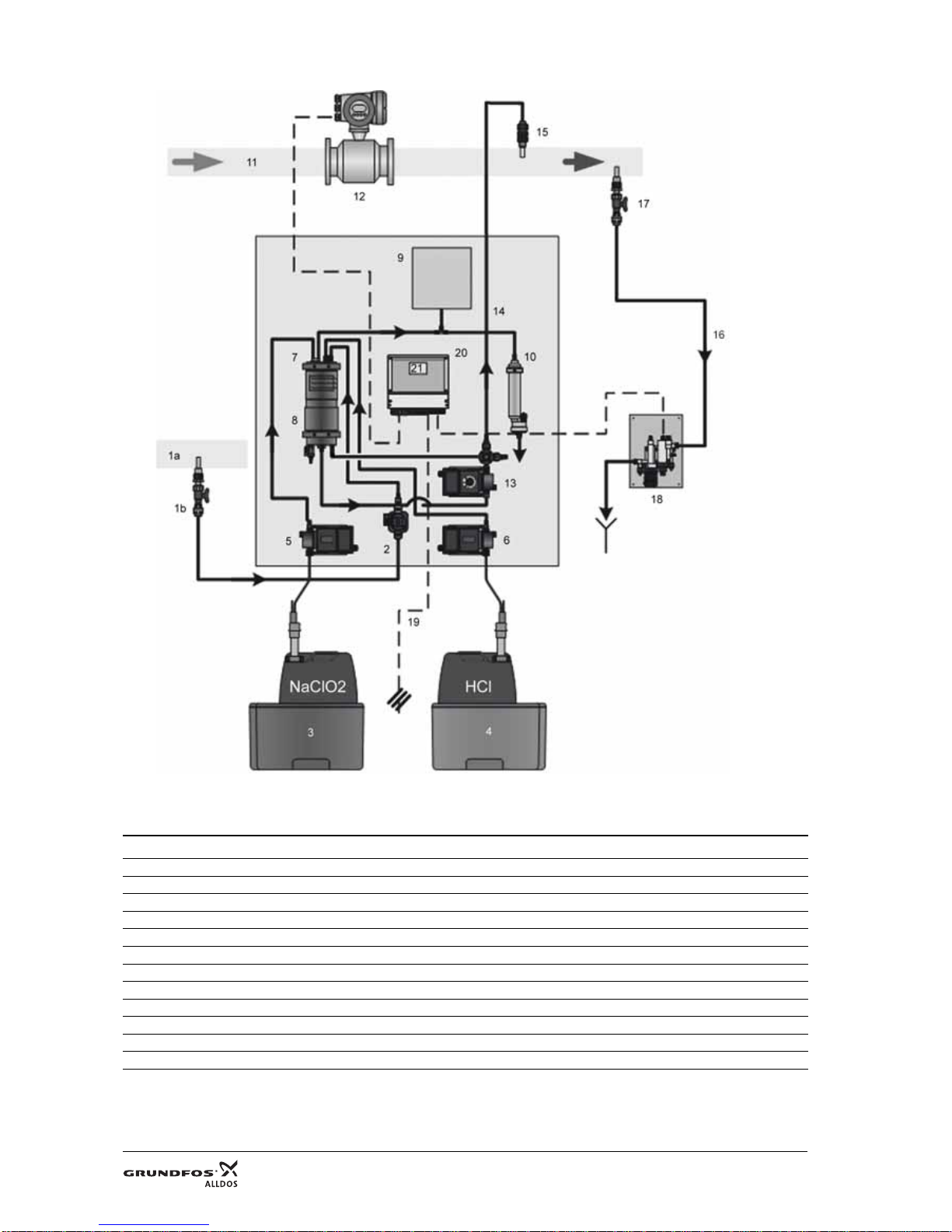
Fig. 5 Components of Oxiperm Pro (here: OCD-162-5, -10)
2.3.1 External parts
See also the photos in section 15. Photos.
TM03 6897 4506
Pos. Components
1a Water line for supplying dilution water and flushing water (via solenoid valve in the device)
1b Extraction point for dilution water with stopcock
3 Chemical container for NaClO
2
(diluted concentration of 7.5 % by volume) with suction lance and collecting tray
4 Chemical container for HCl (diluted concentration of 9 % by volume) with suction lance and collecting tray
11 Main water line to be disinfected
12 Flow meter (or contact water meter)
14 Dosing line
15 Injection unit for dosing the ClO
2
16 Measuring water pipe
17 Measuring water extraction point
18 Measuring cell for checking the chlorine dioxide concentration in the main line (optional)
19 Power supply connection
Blue Red
Page 13

13 / 152
2.3.2 Internal components
Pos. Components
2 Solenoid valve for supplying dilution water and flushing water
5 Chemical pump for sodium chlorite (pump 2)
6 Chemical pump for hydrochloric acid (pump 1)
7 Reaction tank with float switch
8 Chlorine dioxide reservoir tank with float switch and drain cock (bottom left)
9 Volume compensation bag for ClO
2
gas
10 Activated carbon filter for ClO
2
gas
13 Dosing pump with multi-function valve
20 Electronic control system with measured-value sensor for check measurements
21 Display with control and display elements
Page 14
14 / 152
2.4 System peripheral devices and accessories
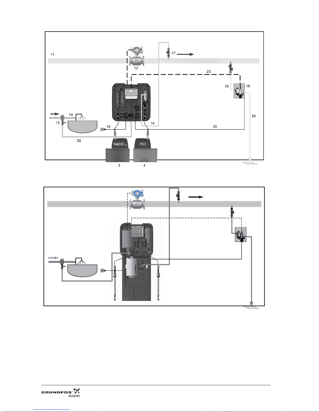
Fig. 6 Complete OCD-162-5, -10 system with measuring cell and without extension module
Fig. 7 Complete OCD-162-30, -60 system with measuring cell and without extension module
TM03 6918 4506TM03 0875 1509
Red
Blue
17
1a
14
1b
19
15
23
26
12
24
25
16
18
17
11
Page 15

15 / 152
2.4.1 Accessories for the dilution water line (not included)
• Stopcock (ball valve)
• Tapping sleeve for dilution water extraction (optional) (if necessary, with double nipple and connection piece for
hose) (optional).
• Hose with connection to solenoid valve.
Stopcock and tapping sleeve are not required, if the bypass mixing module with dilution water connection has been
selected.
2.4.2 Accessories for the main water line (not included)
• Contact water meter or fitted flow meter (in case of a new water line, water flow meter that provides signals or
ultrasonic flow meter).
• Tapping sleeve for the injection unit (optional).
• Protective pipe for the dosing line, installed from the dosing pump to the injection unit (optional).
• Grundfos Alldos DIT photometer (measures ClO
2
concentration after dosing) (optional).
2.4.3 Measuring cell (optional)
• Measuring cell
• Tapping sleeve for sample-water extraction at the main line (not included).
• Hose from the sample-water extraction point to the measuring cell.
• Hose from the measuring cell to the sample-water drain.
2.4.4 Extension modules (optional)
The standard system can be extended using modules:
• measuring cell for cold and hot water (main water up to 50 °C, pressure 4 bar) for connection to the Oxiperm Pro
• measuring module for cold and hot water (main water up to 70 °C, pressure 8 bar) for connection to the
Oxiperm Pro
• bypass mixing module for cold and hot water for connection to the Oxiperm Pro (separate installation and operating
instructions).
Pos. Components
1a
Water line for supplying dilution water and flushing water (via solenoid
valve in the device)
1b Extraction point for dilution water with stopcock
3
Chemical container for NaClO
2
(diluted concentration of 7.5 % by volume)
with suction lance and collecting tray
4
Chemical container for HCl (diluted concentration of 9 % by volume) with
suction lance and collecting tray
11 Main water line to be disinfected
12 Flow meter (or contact water meter)
14 Dosing line
15 Injection unit for dosing the ClO
2
16 Hose for sample-water extraction
17 Sample-water extraction point
18 Measuring cell
19 Power supply connection/main switch
23 Connection cable for measuring cell
24 Sample-water drain
25 Connection cable for cleaning motor
26 Hose for dilution water
Note
In case of fluctuating flow rates in the main water flow, the use of a bypass mixing module is
recommended in order to optimise mixing and red uce the risk of corrosion . See the separate
installation and operating instructions for the bypass mixing module .
Page 16

16 / 152
2.5 Power supply connections and electronic connections
The Oxiperm Pro disinfection system is equipped with an electronic control system. See fig. 8.
The control system has connections for the following:
• power supply cable to the main switch
• cable from the water flow meter or flow meter
• cable from external batch tank to level control, if necessary
• cables for measuring cell AQC-D1 or AQC-D6, if necessary:
– measuring electrode and counter-electrode
– sample-water deficiency sensor
– Pt100 sensor
– pH electrode, if necessary (for pH or ORP) (AQC-D1 only)
– cleaning motor (AQC-D1 only)
• or the cables from the measuring module, if necessary:
– measuring electrode and counter-electrode
– water sensor
– Pt100 sensor
• or the cable from the mixing module, if necessary:
– flow controller.
For additional connections, see section 4.7 Connecting the electronic components.
2.6 Control and display elements
Fig. 8 The display and control panel
2.6.1 Using the control panel
TM03 6920 4506
Buttons and LEDs Functions
[Esc] button Cancels command, exits menu
[Up] button Selects the previous menu item or sets a higher numerical value
[Down] button Selects the next menu item or sets a lower numerical value
[OK] button Confirms the menu selection
[Cal] button Calibration
[Man] button Manual operation
"Alarm" LED Alarm (red)
"Caution" LED Warning (yellow)
"Cal" LED Calibration (yellow)
"Man" LED Manual operation (yellow)
Page 17

17 / 152
2.6.2 Using the display
After switching on the system (not initial start-up), the following display appears:
Fig. 9 Display level after starting the system
The header indicates the status (here: no process started). For symbols and numbers for relays, see the table below.
Press [OK] to access the MAIN MENU:
During operation, press [Esc] to access the display level:
Fig. 10 PROCESS RUNNING display level
Messages in the display level
TM03 6921 4506
MAIN MENU
PROCESS
CONTROLLER
ClO
2
ALARM
SERVICE
SETUP
MAINTENANCE
TM03 6922 4506
Number or
symbol
Message in the
display level
Meaning of the message
1
Headers
PROCESS
RUNNING
ClO
2
production is active.
PROCESS STOP ClO
2
production has been stopped.
PROCESS
ABORT
ClO
2
production has been aborted by a menu command or alarm.
FLUSHING Flushing is started automatically or manually.
2
Relays
1
Relay for solenoid valve.
Display:
White number on a black background: relay active.
Black number on a white background: relay not active.
2
Relay for HCl pump:
display as for 1.
3
Relay for NaClO
2
pump:
display as for 1.
4
Alarm relay:
display as for 1.
5
Warning relay:
display as for 1.
54321
.........
24
,
5
°C
pH
7
,
35
5
4
3
2
1
0,23 mg
/
l
1
2
6
7
4/3
5
8
PROCESS RUNNING
Page 18

18 / 152
3
Symbol
Symbol for relay for the pulse pause controller.
Symbol for controller stop for the pulse pause controller.
4
Symbol
Symbol for continuous controller.
Box with plotted line.
The height of the line is proportional to the actuating variable (ClO
2
dosing volume).
Line not visible:
actuating variable = 0 %
Line fills the entire box:
actuating variable = 100 %
Symbol for stop of continuous controller.
White box with a diagonal line through it.
5
Symbol
Symbol for external disturbance value input (water flow as pulse or current signal).
Box with plotted triangle.
The black fill is proportional to the flow (the greater the fill, the greater the flow, 0-100 %).
(Only visible if proportional or combined controller is configured.)
6
Val ue
e.g. 24.5 °C Water temperature, display value is only available with connected measuring cell.
7
Val ue
e.g. 0.23 mg/l ClO
2
concentration, display value is only available with connected measuring cell.
8
Val ue
e.g. 7.35 pH value in the sample water, display value is only available with connected measuring cell.
Number or
symbol
Message in the
display level
Meaning of the message
6
6
Page 19

19 / 152
2.7 Operating modes
During the commissioning process, you set up the disinfection system in accordance with the application.
After switching on and starting up ClO2 production via menu commands, the system runs fully automatically.
Two operating modes are available for the production of ClO
2
(see section 5.14 Setting the operating mode):
• continuous operation ("continuous" mode)
• single operation ("once" mode).
• external batch tank ("ext. batch" mode)
The appropriate dosing for the application is set at the dosing pump and via the controller parameter settings.
Dosing takes place automatically.
Manual operation is used for shutting down the controller (see section 5.14 Setting the operating mode) and for
temporary manual control if required (pulse dosing).
2.8 Access codes
When the system is ready for operation, the MAIN MENU cannot be accessed without a code.
Two different access authorisations/security levels are assigned for all submenus. Each code automatically enables the
levels below it too.
• User code: By default, all user menus can initially be accessed without a code request.
(When the menu selection has been confirmed using [OK], a code request is not displayed.)
Once the user has entered his/her own user code (MAIN MENU – SETUP – CHANGE CODE), the code request
appears before any user submenu can be accessed. The modified user code must only allow access for trained
users with appropriate technical training and experience. Access is enabled for 60 minutes after entry of the code.
• Service code: This code is reserved for trained Grundfos Alldos service engineers. Access is enabled for
30 minutes after entry. The service code is necessary for commissioning. See section 5.4 Switching on the system
– initial start-up.
• Super-user code: Some menus in the maintenance section are only accessible with a super-user code.
They are not described in these instructions.
For details of how to change the user code, see section Modifying setup in the separate installation and operating
instructions. This is only needed for basic factory settings.
Page 20

20 / 152
2.9 User menu structure
Users can view certain submenus in the display and can also modify certain values.
2.9.1 Finding user menus
In the following tables, the first column indicates whether users can access a submenu:
• without a code (0)
• with the user code (A).
Users can access the following submenus from the MAIN MENU (without a code or with the user code):
User menus,
Note
All software menus can be selected from the MAIN MENU using the [Up] and [Down] buttons
and accessed using [OK].
Press [Esc] to return to the menu level above.
For operating instructions for each menu, see se ction 5. Commissioning.
Code Main menu Submenu 1 Submenu 2 Submenu 3 Submenu 4 Submenu 5
A
Main menu
Process
Start
Star t
Start ClO
2
production?
ABack
A
Abortion
Abortion
Abort ClO
2
production?
ABack
A
Operation
continuous
A once
A ext. batch
0
Service
Process
Status
Display:
Process Status
0 List of events
0
ClO
2
production
Cycles
0
Chemicals
HCl/NaClO
2
since 14.09.2006
HCl (l)
NaClO
2
(l)
reset
0 Age of ClO
2
(mm:ss)
0 Maintenance
A
Flushing
Start
A Abortion
0
Measurement
ClO
2
Measured value
0 CalData/logbook
0 Temperature
°C or °F
Measured value
0
pH or ORP
Measured value
0 CalData/logbook
0ClO
2
controller
Display:
Controller setting
0
Water flow meter
1.00 - 100.00 pulses/
sec.
(Note 5*)
50 pulses/sec., 50 %*
(or: 5 mA, 25 %)
0 Test display
Program version
Page 21

21 / 152
Notes to table:
Note 4*:
• The ALARM settings are only available when MEASUREMENT has been enabled (using the service code).
• The alarm relay is activated if previously set alarm values for chlorine dioxide are exceeded or not reached, if the
maximum dosing time is exceeded, and in case of a fault.
Note 5*:
The WATER FLOW METER submenu only appears if a WATER FLOW METER is enabled (using the service code).
Menus for service engineers
Initial start-up is carried out using a special service code.
After initial start-up, the service engineer can access the service menus using this service code. The following
submenus can be opened from the main menu using the service code:
A
Main menu
Setup
Language
Deutsch
A English
A (all listed)
A
Date/time
Date
ATime
A Daylight sav. t.
Begin, end, time shift
(± x hours), off
A
Code function
Change
A Delete
A Display Contrast 50 %
0
A
Alarm
(Note 4*)
ClO
2
alarm values
Alarm off
A
Alarm on
Alarm value 1
0.15 mg/l
Upward
violation or
downward viol.
A
Alarm value 2
0.70 mg/l
Upward
violation or
downward viol.
A
Hysteresis
0.01
A
Alarm delay
0 sec.
A Dos. time monit. Off/On
A
Calibration
Chlorine dioxide
Cal. meas. value
A Cal. result Slope µA, mg/l
A Cal. cycle On/Off
A
pH
Cal. meas. value
Grundfos, DIN/Nist,
other
ACal. result
Slope µA, mg/l
asym. mV
A Cal. cycle On/Off
A
ORP
Cal. meas. value
A Cal. result Asym. mV
A Cal. cycle On/Off
HB
Manual
operation
ClO
2
controller On/Off
Code Main menu Submenu 1 Submenu 2 Submenu 3 Submenu 4 Submenu 5
Page 22

22 / 152
2.9.2 Menus for service engineers, table 1
Notes to menus for service engineers, table 1:
(* 1) PROPORT. and COMBINED CONTRL only appear if a water flow meter has been defined under SETUP > WATER FLOW METER.
Otherwise, only SETPOINT CONTRL appears.
Code Main menu Submenu 1 Submenu 2 Submenu 3 Submenu 4 Submenu 5
0
Main menu
S
Setup
Measurement
Measuring cell
AQC-D1
AQC-D6
off
S
ClO
2
ClO2 + pH
ClO
2
+ ORP
S
Measuring
range
ClO
2
0.00 - 1.00
S
Temperature
0-100 °C
S pH 0.00 - 14.00
S ORP 0-1000
S
Water flow
meter
Off
S Pulse x l/pulses
S
Current
0-20 mA
4-20 mA
others
x m
3
/h
S
Relay
Warning relay
Fail safe
On (N.C.)
Off (N.O.)
SAlarm relay
Fail safe
On (N.C.)
Off (N.O.)
S
Current output
Control
0-20 mA
4-20 mA
others
S Measurement ClO
2
0-20 mA
4-20 mA
others
S
Factory setting
Setup
Save
S Activate
S Reset (Factory code)
S
ClO
2
controller
Proport. contrl
(Note * 1)
Interpulse ctrl.
S
Cont. controller
0-20 mA
S
Setpoint contrl
Interpulse ctrl. P, PI, PID
S
Cont. controller
0-20 mA
P, PI, PID
S
Combined contrl
(Note * 1)
Interpulse ctrl. P, PI, PID
S
Cont. controller
0-20 mA
P, PI, PID
SOFF
Page 23

23 / 152
Menus for service engineers, table 2
Code Main menu Submenu 1 Submenu 2
Factory
setting
Submenu 3 Factory setting
S
Main Menu
Controller ClO
2
(Note * 1 b)
(for
proportional
controller –
continuous
controller)
Added quantity 0.4 mg/l ClO
2
S Min. switch-on 1.0 s
S Max. dosing flow 100 %
S Controller stop N.O.
S Max. dosing flow 100 %
S Controller stop N.O.
S
Dosing pump
Stroke adjustm. 100 %
S
Dosing capacity
DMI 3.0-10 with OCD-162-5: 3.0 l/h
S DDI 5.5-10 with OCD-162-5: 2.3 l/h
S DMI 6.0-8 with OCD-162-10: 6.0 l/h
S DDI 5.5-10 with OCD-162-10: 5.0 l/h
S DMX 16-10 with OCD-162-30: 16 l/h
S DDI 60-10 with OCD-162-30: 16 l/h
S DMI 35-10 with OCD-162-60: 35 l/h
S DDI 60-10 with OCD-162-60: 35 l/h
S
Controller
(Note * 2 a)
(for setpoint
controller –
interpulse
controller)
Min. switch-on 1.0 s
S Max. dosing flow 100 %
S Controller stop N.O.
S Set point 0.40 mg/l ClO
2
S Prop.range XP 30 %
S Reset time TN 60 s
S Deriv. action TV 0 s
S
Controller
(Note * 2 b)
(for setpoint
controller –
continuous
controller)
Max. dosing flow 100 %
S Controller stop N.O.
S Set point 0.40 mg/l ClO
2
S Prop.range XP 30 %
S Reset time TN 60 s
S Deriv. action TV 0 s
S
Controller
(Note * 3 a)
Combined
controller –
interpulse
controller
Min. switch-on 1.0 s
S Max. dosing flow 100 %
S Controller stop N.O.
S Set point 0.40 mg/l ClO
2
S Prop.range XP 30 %
S Reset time TN 60 s
S Deriv. action TV 0 s
S
Dosing pump
Stroke adjustm. 100 %
S
Dosing capacity
DMI 3.0-10 with OCD-162-5: 3.0 l/h
S DDI 5.5-10 with OCD-162-5: 2.3 l/h
S DMI 6.0-8 with OCD-162-10: 6.0 l/h
S DDI 5.5-10 with OCD-162-10: 5.0 l/h
S DMX 16-10 with OCD-162-30: 16 l/h
S DDI 60-10 with OCD-162-30: 16 l/h
S DMI 35-10 with OCD-162-60: 35 l/h
S DDI 60-10 with OCD-162-60: 35 l/h
Page 24

24 / 152
* 1 a, 1 b, 2 a, 2 b, 3 a, 3 b: Only appears if the controller has been defined under the service code in MAIN MENU > SETUP > ClO2 CONTROLLER
and parameterised in the ClO
2
CONTROLLER menu.
(* 1 a) If proportional controller – interpulse controller has been selected.
(* 1 b) If proportional controller – continuous controller has been selected.
(* 2 a) If setpoint controller – interpulse controller has been selected.
(* 2 b) If setpoint controller – continuous controller has been selected.
(* 3 a) If combined controller – interpulse controller has been selected.
(* 3 b) If combined controller – continuous controller has been selected.
Menus for service engineers, table 3
Notes to menus for service engineers, tables 2 and 3:
(* 4) Temperature correction is active if ON is selected in SETUP – MEASUREMENT. The resistance of the Pt100 resistance thermometer is higher
on long lines. The additional line resistance is offset with this menu function (for unit, see SETUP – MEASURING RANGE).
S
Main Menu
Controller
(Note * 3 b)
Combined
controller –
continuous
controller
Max. dosing flow 100 %
S Controller stop N.O.
S Set point 0.40 mg/l ClO
2
S Prop.range XP 30 %
S Reset time TN 60 s
S Deriv. action TV 0 s
S
Dosing pump
Stroke adjustm. 100 %
S
Dosing capacity
DMI 3.0-10 with OCD-162-5: 3.0 l/h
S DDI 5.5-10 with OCD-162-5: 2.3 l/h
S DMI 6.0-8 with OCD-162-10: 6.0 l/h
S DDI 5.5-10 with OCD-162-10: 5.0 l/h
S DMX 16-10 with OCD-162-30: 16 l/h
S DDI 60-10 with OCD-162-30: 16 l/h
S DMI 35-10 with OCD-162-60: 35 l/h
S DDI 60-10 with OCD-162-60: 35 l/h
Code Main menu Submenu 1 Submenu 2 Submenu 3 Submenu 4 Submenu 5
S
Main menu
Service
Test current
Control
measurement ClO
2
0/4 mA on/off
10/12 mA off/on
20 mA off/on
STest relay
Test relay off/on
SV H
2
O off
Pump HCl off
Pump NaCl
2
off
Pump ClO
2
off
Alarm relay off
Warning relay off
S
Test level
Reaction tank
S Reservoir tank
S Ext. batch tank
S suction line
S
Maintenance
Maintenance rel.
S
Temp. correction
(Note * 4)
S
Manual
operation
Dosing flow
Cont. controller or
Interpulse
controller
xx % dosing flow
Code Main menu Submenu 1 Submenu 2
Factory
setting
Submenu 3 Factory setting
Page 25

25 / 152
3. Transport and packaging
3.1 Unpacking
Number of packing units: 1 box.
Procedure:
1. Unpack the device.
2. Unpack the cover.
3. Unpack the measuring cell, if supplied.
4. Unpack the extension modules, supplied.
5. Retain the original packaging in order to return the device for servicing.
6. Check the device(s) for transport damage (especially hoses and lines).
3.2 Transport damages
In case of transport damage:
1. Pack the device in its original packaging.
2. Inform the forwarder of the transport damage.
3. Return the device to the supplier.
Warning
Increased risk of damage to equipment and personal injury as a result of operatin g faults due
to transport damage.
Do not shake, crush or drop the box. Open th e packag ing ca refully.
Do not use a sharp or pointed blade.
Carefully remove the device from the box. Do not bend the hoses and cables.
Note
Do not adjust the stroke-length adjustment knob on the pump. It must no t be adjuste d until the
pump is running.
Box
Dimensions
L x W x H
[mm]
Contents Weight gross / net
1 900 x 900 x 518
Device with cover, hoses, screws, accessories
OCD-162-5: 30 kg / 26 kg
OCD-162-10: 32 kg / 28 kg
1 766 x 558 x 1813
OCD-162-30-D: 80 kg / 70 kg
OCD-162-30-P: 79 kg / 69 kg
1 766 x 558 x 1813
OCD-162-60-D: 100 kg / 85 kg
OCD-162-60-P: 99 kg / 84 kg
Page 26

26 / 152
4. Installation
Installation faults may give rise to a number of risks:
4.1 Installation location
The operator must ensure that all the conditions listed below for structurally and technically safe and optimum operation
of the system are met prior to commencing installation.
An installation location must be provided that fulfils the following:
• It is protected from the sun, frost-proof, well-ventilated and has sufficient lighting (the system must not be installed
outdoors).
• It meets the conditions specified in section 11. Technical data regarding air temperature, humidity, permissible
component operating temperature and dilution water quality.
• It has steel or concrete walls, which enable the OCD-162-5, -10 system to be wall-mounted (minimum wall
thickness of 10 cm for the mounting screws) or the OCD-162-30, -60 floor-mounted system to be fixed.
• It has a power supply connection (see section 11. Technical data).
• It has access to the main water line.
• It has a connection for dilution water of drinking water quality in accordance with TrinkwV 2001.
• It has a floor drain for washing away chemicals and a drain (tank) for sample water.
• It has a separate storage room for empty and full chemical containers.
• It is isolated from other areas with regard to fire protection.
• It is secured against unauthorised access and meets the regulations for the prevention of accidents.
• It is not in permanent use by personnel (maximum stay: two hours).
Warnin g
Incorrect installation may result in serious personal in jury and damag e to property.
Only authorised and qualified personnel may install the system.
Warnin g
Risk of corrosion damage to electro nic circu its a nd gas poisoning d ue to th e escape of
gaseous ClO
2
from a damaged volume compensation bag.
• Do not reach into the void behind the contro l unit.
Risk of severe burns resulting from the spray of chemicals from damaged seals, valves, h ose
connections or hoses or from handling chemicals.
• Do not bend the hoses. Route them directly down from the unit where possible, and connect
with care. Tighten nuts by hand only.
• Wear protective clothing (safety goggles, gloves, protective apron, breathing mask, if
necessary).
• Do not mix up containers. Always check the label. Do not use cleaning agents.
Warnin g
Risk of fire and corrosion due to incorrect storage of chemicals. Do not store hydrochloric acid
and sodium chlorite near grease, flammable or oxidising substances, oils, acids or salts.
Obtain approval for storing chemicals.
Page 27

27 / 152
4.1.1 Operator’s checklist
4.1.2 Preparing the installation site
4.1.3 Preparing tools and protective clothing
• Hand drill with masonry bit, diameter 10 mm.
• Protective clothing in accordance with the German GUV-V D5. See section 1.4 Obligations of the operator.
Operator’s checklist – preparing for installation
Done
1. Read the installation and operating instructions for Oxiperm Pro and for the dosing pumps
DMI 208, DDI 209, DMX 221 or DDI 222, if applicable, as well as for the multi-function valve, the
measuring cell and the extension module, if used. Store the manuals in a dry place in the
installation location.
2. Measure the pressure and temperature in the dilution water line and in the main water line.
3. Measure the room temperature and the humidity.
4. Obtain official approval for storing chemicals, if necessary.
5. Purchase accessories. See section 14. Operator’s accessories list.
6. Fit a tapping sleeve for the dilution water supply in the drinking water line.
7. Fit a tapping clamp for the injection unit in the main line.
8. Install a protective pipe for the dosing line, if necessary.
At the main line:
9. Fit a tapping sleeve for sample-water extraction, if necessary.
10.Fit tapping sleeves for the measuring or mixing module, if used.
11.Provide protective clothing in the room in accordance with the regulations for the prevention of
accidents (German GUV-V D5).
12.Display a "No fires, naked flames or smoking" warning sign. Display all warning signs provided.
Checklist for service engineers – carry out installation tasks
Done
• Check that all connections to the main line are installed.
• Check that all necessary parts have been supplied (chemical containers, hoses, cables).
• Fix the unit on the wall or on the floor. See the mounting diagram (fig. 11) and the dimensional
sketch (fig. 12).
• Mount the measuring cell (if applicable) (see the mounting diagram in the installation and operating
instructions for the measuring cell).
• Mount the measuring or mixing module (if applicable).
• Connect the hydraulic components:
- dilution water hose to solenoid valve
- dosing line to injection unit
- dosing line from supply bottle to external dosing pump (if applicable).
• Install the chemical containers, and attach the suction lances.
• Connect the hydraulic components to the measuring cell (if applicable).
• Connect the hydraulic components to the measuring or mixing module (if applicable).
•Route the cables through the glands into the control unit.
• Connect the electronic components:
- contact water meter/flow meter
- measuring cell AQC-D1 or AQC-D6 (if applicable)
- measuring or mixing module (if applicable)
- higher-level control system (if applicable)
- warning lamp or audible warning system (if applicable)
- gas detector (if applicable)
- external non-switching device (if applicable).
• Connect the power supply cable.
• Fit the cover.
Page 28

28 / 152
4.2 Mounting the unit on the wall (OCD-162-5/-10)
See the mounting diagram, fig. 11, and the dimensional sketch, fig. 12.
Minimum wall thickness (brick or concrete): 100 mm.
1. Mark the below centre drill hole of the system frame (maximum 1400 mm above the ground).
2. From the below centre drill hole, mark the left drill hole 430 mm above and 250 mm to the left.
3. From the below centre drill hole, mark the right drill hole 430 mm above and 250 mm to the right.
4. Allow a minimum distance from the top of the system frame to the ceiling of 190 mm.
5. The drill holes (∅10 mm) must have a minimum depth of 70 mm.
Insert SX dowel pins (dowel pin length: 50 mm), and screw in hanger bolts to a depth of 55 to 60 mm.
6. Get two people to lift up the system frame and position it on the hanger bolts.
7. Secure with a nut and washer on each bolt, and fit protective caps on top.
Page 29

29 / 152
4.3 Mounting the unit on the floor (OCD-162-30/-60)
See the mounting diagram, fig. 11 (identical with the unit OCD-162-5) and the dimensional sketch, fig. 13.
1. Get two people to carry the unit to the place where it will be commissioned. The ground has to be even.
The ceiling height must be at least 2.20 m.
2. Mark the four drill holes, e.g. with a punch, and put the unit aside.
3. Drill the holes (∅10.5 mm) with a minimum depth of 70 mm and insert SX dowel pins (length: 50 mm).
4. Place the unit at the desired position and screw in the screws with washers.
4.3.1 Checking the mounting diagram
Fig. 11 Mounting diagram for the Oxiperm Pro (here: OCD-162-5) with measuring cell and mixing module (22)
Minimum distance between injection unit and measuring point = 3 metres.
TM03 6923 4506
Pos. Components
1a Water line for supplying dilution water and flushing water (via solenoid valve in the device)
1b Extraction point for dilution water with stopcock
3 Chemical container for NaClO
2
(diluted concentration of 7.5 % by volume) with suction lance and collecting tray
4 Chemical container for HCl (diluted concentration of 9 % by volume) with suction lance and collecting tray
11 Main water line to be disinfected
12 Flow meter (or contact water meter)
14 Dosing line
16 Hose for sample-water extraction
17 Sample-water extraction point
18 Measuring cell
19 Power supply connection/main switch
23 Connection cable for measuring cell
24 Sample-water drain
25 Connection cable for cleaning motor
26 Hose for dilution water
Blue
Red
Page 30

30 / 152
4.3.2 Dimensional sketch OCD-162-5, -10
Fig. 12 Dimensional sketch of unit with drill holes (OCD-162-5, -10)
Mounting height: display at eye level.
Distance from ground to lower edge of system frame: maximum 1.145 m.
Length of suction hoses: maximum 1.30 m.
Distance from top edge of unit to ceiling: minimum 19 cm.
Allowance on either side: minimum 20 cm.
TM03 6924 4506
1910 mm
765 mm
765 mm
328 mm
1145 mm
500 mm
10,5 mm
430 mm
1400 mm
250 mm
190 mm
NaClO2
HCL
250 mm
430 mm
max.1400 mm
765 mm
max. 1910 mm
max. 1145 mm
min.
190 mm
328 mm
∅10.5 mm
765 mm
500 mm
250 mm
250 mm
NaClO
2
HCl
Page 31

31 / 152
4.3.3 Dimensional sketch OCD-162-30, -60
Fig. 13 Dimensional sketch of unit with drill holes (OCD-162-30, -60)
Length of suction hoses: maximum 6.00 m.
Ceiling height: minimum 2.20 m.
Allowance on either side: minimum 20 cm.
TM04 0952 1709
1800
766
568
50
660
580
A-A
320
10,5
o
A
A
500
Page 32

32 / 152
4.4 Additional modules
Additional modules such as a measuring cell or a measuring/mixing module (if applicable) must be fixed onto the wall.
See the installation and operating instructions for the respective additional modules.
4.5 Installing the chemical containers and attaching the suction lances
1. Screw the intake-side hose connection on the HCl suction lance (red mark) onto the hose connection on the
HCl pump (red mark) (see fig. 15, pos. 6b).
Fig. 14 Correct orientation of the float
2. Position the HCl container in the red collecting tray on the right under the unit (for containers up to 30 g/h for
OCD-162-5, -10) or next to the unit (OCD-162-30, -60).
3. Unscrew the cover. Immerse the suction lance with the red mark in the container. Screw the cover of the
red marked suction lance onto the container.
4. Keep the original cover for storing the empty container.
5. Screw the hose connection of the NaClO
2
suction lance (blue mark) onto the hose connection on the NaClO2
pump (blue mark) (see fig. 15, pos. 5b).
6. Position the NaClO
2
container in the blue collecting tray on the left under the unit (for containers up to 30 g/h
for OCD-162-5, -10) or next to the unit (OCD-162-30, -60) .
7. Unscrew the cover. Immerse the suction lance with the blue mark in the container. Screw the cover of the
suction lance onto the container. Keep the original cover for storing the empty container.
Warnin g
Kinked hoses and lines may result in personal injury a nd damag e to p roper ty. Route the hoses
directly down from the unit where possible, do not lay in loops. Do not kink the suction lines
and cables.
Warnin g
Malfunctions due to the mix-up of chemical containers or suction lances may result in serious
personal injury, damage to property and risk of explosion. Always check the re d and blue
labels on chemical containers, suction lances and pumps.
Note
Check the correct orientation of the float at the suction lances. See fig. 14.
The symbol "normally opened" must be visible on top!
TM04 0854 0908
Page 33

33 / 152
4.6 Hydraulic connections
4.6.1 Hydraulic connections Oxiperm Pro (OCD-162-5, -10)
Fig. 15 Hydraulic connections Oxiperm Pro OCD-162-5, -10
TM03 6899 4506
Position Device connections of the Oxiperm Pro
5b, 6b Hoses for both suction lances on the suction side of the chemical pumps
8b Hose at the drain cock of the reservoir tank (only installed for flushing and ventilation)
14
Dosing line from the dosing pump to the injection unit at the main line or to the injection unit at the mixing module or to
the external batch tank
26 Dilution water hose at the solenoid valve
8b
6b
14
26
5b
Page 34

34 / 152
4.6.2 Hydraulic connections Oxiperm Pro (OCD-162-30, -60)
Fig. 16 Hydraulic connections Oxiperm Pro OCD-162-30, -60
For nominal width of the hose connections, see section 11. Technical data.
4.6.3 Connecting the system frame
For nominal diameters of the hose connections, see section 11. Technical data.
1. Close the dilution water stopcock (fig. 4, pos. 1b).
2. Connect the dilution water hose to the stopcock (fig. 5, pos. 1b).
3. Route the hose to the system frame.
4. Connect the hose to the solenoid valve (fig. 15, pos. 26).
Dosing line to injection unit
1. Route the hose from the multi-function valve on the dosing pump (fig. 15, pos. 14) to the injection unit
(in the protective pipe laid by the customer).
2. Connect the hose to the injection unit.
Connect the hose to the drain cock of the reservoir tank (fig. 15, pos. 8b) for flushing and ventilation only.
See section 5.19 Flushing.
TM04 0953 1509
Position Device connections of the Oxiperm Pro
5b, 6b Hoses for both suction lances on the suction side of the chemical pumps
8b Hose at the drain cock of the reservoir tank (only installed for flushing and ventilation)
14
Dosing line from the dosing pump to the injection unit at the main line or to the injection unit at the mixing module or to
the external batch tank
26 Dilution water hose at the solenoid valve
8b
6b
14
26
5b
6b
14
OCD-162-30
OCD-162-60
8b
5b
Page 35

35 / 152
4.6.4 Connecting the dosing line for the external dosing pump (if applicable)
1. Remove the cap from the connector on the reservoir tank.
2. Route the dosing line from the reservoir tank to the external dosing pump, and connect it to the suction valve
on the external dosing pump.
3. Route the overflow line from the external dosing pump back to the reservoir tank, and connect it.
4. Route the dosing line from the external dosing pump to the injection unit, and connect it to the injection unit.
4.6.5 Connecting the hydraulic components to the measuring cell (if applicable)
1. Connect the sample-water hose (fig. 11, pos. 16) to the extraction point in the main line, route it to the
measuring cell, and connect it.
2. Connect the sample-water hose (fig. 11, pos. 24) to the measuring cell, and route it into the drain.
After dosing, the ClO
2
concentration, temperature and pH/ORP value of the sample water are measured in the
measuring cell.
The measuring cell has connections for the following:
• hose from the sample-water extraction point to the measuring cell
• hose from the measuring cell to the drain.
See the installation and operating instructions for the measuring cell.
4.6.6 Measuring module connections
The measuring module is hydraulically connected to the main line.
The measuring module has connections for the following:
• hose from tapping sleeve 1 to the measuring module and hose from the measuring module to tapping sleeve 2 at
the main line.
See the installation and operating instructions for the measuring module.
4.6.7 Mixing module connections
The mixing module is hydraulically connected to the main line and the Oxiperm Pro.
The mixing module has connections for the following:
• dosing line from the Oxiperm Pro dosing pump to the injection unit in the mixing module.
• hose from tapping sleeve 1 to the mixing module and hose from the mixing module to tapping sleeve 2 at the main
line.
See the installation and operating instructions for the mixing module.
Warning
Incorrect installation may result in personal inju ry and damag e to property. Only authorised,
trained service personnel may connect an external dosing pump mo dule to the Oxiperm Pro .
Page 36

36 / 152
4.7 Connecting the electronic components
Fig. 17 Control unit with controls, display elements and cable glands
Most cables are already connected to the control unit on delivery. The following cables need to be connected at the
commissioning stage. See also the terminal connection plan in fig. 53:
4.7.1 Passing the cables through glands into the control unit
1. Unfasten the two screws on the rectangular cover underneath the control unit, and remove the cover.
2. Screw on the corresponding cable gland, and push through the cable.
3. Connect the cable as shown in the terminal connection plan in fig. 53.
4. Close the cable gland by hand.
4.7.2 Connecting the contact water meter/flow meter
1. Route the control cable from the contact water meter/flow meter to the control unit.
2. Connect the control cable to the control unit.
Warnin g
Risk of shock from damaged electronic compone nts (transport damage or installation faults).
Only authorised and qualified personnel may connect the electronic compon ents.
Do not reach into the void behind the control unit. Do not kink cables.
TM03 6926 4506
Connection for
Warning lamp or audible warning system
Contact water meter
Flow meter (current input signal)
Measuring electrode (measuring cell)
Reference electrode (measuring cell)
Counter-electrode (measuring cell)
GND_Cl (measuring cell)
Cleaning motor (measuring cell)
Pt100 temperature sensor
Sample-water deficiency sensor on main line
Fault input, for example gas detector
Flow monitor on mixing module or higher-level control system
Level control external batch tank
Page 37

37 / 152
4.7.3 Connecting the measuring cell (if applicable)
• Connect measuring cell AQC-D1 or AQC-D6 (if applicable):
– measuring and counter-electrode (for measuring ClO
2
)
– sample-water deficiency sensor
– Pt100 sensor
– pH electrode, if applicable (for pH or ORP) (AQC-D1 only)
– cleaning motor (AQC-D1 only).
4.7.4 Connecting the measuring module (if applicable)
• Connect the measuring module to measuring cell AQC-D1 or AQC-D6 (if applicable):
– measuring and counter-electrode for measuring ClO
2
– sample-water deficiency sensor
– Pt100 sensor.
4.7.5 Connecting the mixing module (if applicable)
• Connect the cable from the flow monitor, if applicable (terminals 49/50).
4.7.6 Connecting a higher-level control system (if applic able)
If no mixing module is connected:
• Connect the cable from the higher-level control system to terminals 49/50.
This system can also be used to switch off the Oxiperm Pro controller and hence the dosing pump.
4.7.7 Connecting a warning lamp/warning system (if applicable)
• Connect the cable from the warning lamp or audible warning system to the collective relay for error messages.
In case of power failure, the warning lamp illuminates, if it is connected with the normally closed contact.
Alarm relay
– Terminals 25 and 29 N.C. = normally closed
– Terminals 25 and 27 N.O. = normally open.
Warning relay
– Terminals 26 and 30 N.C. = normally closed
– Terminals 26 and 28 N.O. = normally open.
See section 5.12 Setting the warning and alarm relay.
4.7.8 Connecting the gas detector (if applicable)
• Connect the cable from the gas detector.
4.7.9 Connecting external non-switching devices (if applicable)
• Two external devices can be supplied with power supply voltage. Therefore select free cable glands and connect to
the following terminals:
14/16/18 and 20/22/24.
See section 11.1 Terminal connection plan.
4.7.10 Connecting an external batch tank (if applicable)
• Connection of level sensors from external batch tank to terminals 45, 46, 47 and 48.
– Terminal 45 = Min. level
– Terminal 46 = Max. level
– Terminal 47 = Max-max. level (batch tank is overfull)
– Terminal 48 = Ground
Page 38

38 / 152
4.8 Connecting the power supply cable
1. Check that the voltage corresponds to the value specified on the nameplate.
2. Route the power supply cable up from the unit between the control unit and the reaction tank.
3. Route the power supply cable as far as the main switch.
4. Connect the power supply cable to the main switch.
5. Switch off the main switch.
Warnin g
Incorrect electrical connections may result in serious personal inju ry and damage to pr operty.
Electrical connections may only be carried out by authorised and qualifie d personnel.
Disconnect the power supply cable before starting work.
The power supply connection must be carried out according to the local regulations.
Provide for an all-pole separator.
Warnin g
Position the external circuit breaker as close as possible to the Oxiperm Pr o system.
Prerequisites for the circuit breaker are:
- operating voltage min. 230 V AC
- operating current min. 4A AC
- 2-pole interruption
The protective earth has to be connected with terminal 6, see terminal connection plan, chap.
11.1 Terminal connection plan, fig. 53.
Warnin g
Risk of gas poisoning due to the escape of gaseous ClO2 from damaged volume compensation
bag.
Do not route the power supply cable through the void behind the control unit. Instead route it
up at the side between the control unit and the reaction tank.
Page 39

39 / 152
5. Commissioning
5.1 System configuration
• Make a note of your answers in the checklist:
Warning
Incorrect maintenance may result in significant personal injury and damage to property.
Only authorised and qualified personnel may commission the system.
Warning
Risk of gas poisoning due to the escape of gaseous ClO
2
from damaged volume compensation
bag.
Do not reach into the void behind the control unit.
Warning
Risk of severe burns resulting from the spray of chemicals from faulty seals, valves, hose
connections or chemical hoses. Before commissioning, check the hoses, connections and
pumps for leaks, and check the system for installation faults.
Note
Risk of corrosion damage to the main water line and damage to property due to system
malfunctions resulting from inadequate quality of the dilution water. Pressure, temperature and
drinking water quality must comply with the system specifications. Check the dilution water
before and during commissioning.
Checklist 1 – Note down the system configuration
Yes/No
X
• Which application group does the system belong to? Which controller type should be used?
- Group 1 application – proportional controller.
- Group 2 application – setpoint controller.
- Group 2 application with flow meter – combined controller.
- Group 3 application with external batch tank, without controller.
• Does the main line have the following connected (required for group 1 and 3 applications, required for group 2
applications with combined controller):
- contact water meter
- flow meter.
• Does the main line have the following connected (optional for group 1 application, required for group 2
applications):
- measuring cell for check measurements.
• Which variables are to be measured:
- ClO
2
(select measuring cell AQC-D6 or AQC-D1)
- ClO
2
+ pH (select measuring cell AQC-D1)
- ClO
2
+ ORP (select measuring cell AQC-D1).
• Does the Oxiperm Pro have the following connected:
- measuring module
- mixing module.
• Does the Oxiperm Pro have the following connected:
- external dosing pump
- recorder
- warning lamp or audible warning system
- higher-level control system.
Page 40

40 / 152
5.2 Operating software settings
5.2.1 Dosage ClO
2
The dosage of chlorine dioxide in g/m3 needed to disinfect the water in the main line depends on the flow in the main
line and on the type and level of contamination in the water.
For group 1 applications, set a value of between 0.1 and 0.4 g/m
3
.
(According to German drinking water standards, the chlorine dioxide concentration in drinking water must not exceed
0.4 mg/l (= 0.4 g/m
3
)).
For group 2 applications, you can set a higher value.
5.2.2 Group 1 and group 2 applications
These applications are controlled proportionally to the flow; the signal from the flow meter is sent to the control unit as
the disturbance variable (called "X-IN" here). The dosing flow corresponds to the signal from the controller to the dosing
pump (called "Y-OUT" in the operating software).
In applications controlled proportionally to the flow, Y-OUT is directly proportional to X-IN.
Dosing factor
The Oxiperm Pro control system calculates the dosing factor automatically using the values set by the operator.
Stroke length of the DMI or DMX pump (with mechanical stroke adjustment)
In case of a small ClO
2
dosing volume, there is a risk of chlorine dioxide "clouds". The stroke length can be mechanically
reduced at the dosing pump to minimise these "clouds". When reducing the stroke length, this value has to be entered
into the stroke adjustment MAIN MENU > CONTROLLER ClO
2
> DOSING PUMP > STROKE ADJUSTM..
See section 2.9.2.
Fig. 18 Distribution of dosing volume by various stroke-length adjustments
The stroke-length adjustment knob is only to be adjusted when the dosing pump is running.
5.2.3 Group 2 applications
For group 2 applications which are controlled by means of setpoints, the actual value of the ClO
2
concentration in the
sample water measured by the measuring cell is sent to the control unit.
Enter a setpoint for the target concentration.
The setpoint controller compares the incoming actual values with the setpoint and based on the deviation calculates the
amount of ClO
2
(actuating variable) that is needed to reach the target concentration.
5.2.4 Group 3 applications
For group 3 applications the external batch tank is filled. Dosing is not made with Oxiperm Pro.
ClO
2
production and filling of the external batch tank continues, until the tank is full. If the maximum filling level of the
batch tank (K12) is attained, the pump switches off and ClO2 production in the reaction tank is stopped.
If the minimum level (K11) of the batch tank is attained, the ClO
2
pump starts running and the process is re-started as
described above.
TM03 6930 4506
40
100
Time [seconds]
Stroke length [%]
Stroke adjustment 100 %:
uneven dosing of ClO
2
Stroke adjustment < 100 %:
even dosing of ClO
2
Stroke length [%]
Time [seconds]
Page 41

41 / 152
5.2.5 Software settings
Group 1 applications
Parameters printed in italics apply only to proportional controllers and combined controllers.
Checklist 2 – your settings
(for group 1 applications)
Your values OK
• Service code for operating software
• Commissioning date
• Commissioning time
• Setting language
• Factory settings
- Retain all factory settings
- Save changes
• Water flow meter impulse rate (xxx l/imp)
• Maximum flow Qmax. (m
3
/h)
• Flow meter current
- 0-20 mA
- 4-20 mA or other
• MEASURED VALUES in the measuring cell (if applicable)
- ClO
2
+ pH
- ClO
2
+ ORP or ClO
2
• MEASURING RANGES (if applicable)
See section 5.8 Assigning measuring range(s) (if applicable).
- For ClO
2
concentration in sample water
- For sample-water temperature
- For pH or ORP in sample water
• Output current to external device (if applicable)
- Controller settings for group 1:
- Controller type
Proportional controller
- Interpulse or continuous controller?
• DOSING COEFFIC. (calculated)
• DOSING FLOW in percent (calculated)
- Stroke length setting in percent
- Dosage in g/m
3
(mg/l)
- Once mode or continuous mode
- For other control parameters, see section 5.10.3 Parameterising the selected controller.
• Output current to external dosing pump (if applicable)
• ALARM RELAY
- Alarm value 1
- Alarm value 2
- Hysteresis
- Alarm delay
- Dosing time monitoring
- Reservoir tank empty signal
Page 42

42 / 152
Group 2 applications with/without flow meter
Parameters printed in italics apply only to combined controllers.
Checklist 2 – your settings
(for group 2 applications with flow meter)
Your values OK
• Service code for operating software
• Commissioning date
• Commissioning time
• Service engineer language
• User language
• Factory settings
- Retain all factory settings
- Save changes
• Flow meter current (if used)
• Measured values in the measuring cell (if applicable)
- ClO
2
+ pH
- ClO
2
+ ORP or ClO
2
• MEASURING RANGES (if applicable)
See section 5.8 Assigning measuring range(s) (if applicable).
- For ClO
2
concentration in sample water
- For sample-water temperature
- For pH or ORP in sample water
• Output current to external device (if applicable)
• Controller type for group 2 (without flow meter) Setpoint controller
• Controller type for group 2 (with flow meter) Combined controller
- Interpulse or continuous controller?
- P, PI or PID?
• DOSING FLOW in percent
- Stroke length setting in percent
- Target concentration in g/m
3
(mg/l)
- SET POINT
- Once mode or continuous mode
- For other control parameters, see section 5.10.3 Parameterising the selected controller.
• Output current to external dosing pump (if applicable)
• ALARM RELAY
- Alarm value 1
- Alarm value 2
- Hysteresis
- Alarm delay
- Dosing time monitoring
- Reservoir tank empty signal
Page 43

43 / 152
Group 3 applications with/without flow meter
Checklist 2 – your settings Your values OK
• Service code for operating software
• Commissioning date
• Commissioning time
• Service engineer language
• User language
• Factory settings
- Retain all factory settings
- Save changes
• Measured values in the measuring cell (if applicable)
- ClO
2
+ pH
- ClO
2
+ ORP or ClO
2
• MEASURING RANGES (if applicable)
See section 5.8 Assigning measuring range(s) (if applicable).
- For ClO
2
concentration in sample water
- For sample water temperature
- For pH or ORP in sample water
- External batch mode
• ALARM RELAY
- Alarm value 1
- Alarm value 2
- Hysteresis
- Alarm delay
Page 44

44 / 152
5.3 Commissioning procedure
Carry out initial commissioning by reference to checklist 3:
Checklist 3 – commissioning procedure Section OK
• Read this manual.
• Check the installation visually (hoses, lines, connections).
• Set the water flow meter, if necessary. 5.6
• Set the measurement, the measured variables, the measuring ranges, if necessary
(if measuring cell connected).
5.7
• Set the current output for external device (if applicable). 5.9
• Set the controller (not applicable for group 3 applications). 5.10
• Set the current output for the external dosing pump (if applicable.) 5.11
• Set the warning and alarm relay. 5.12
• Set the mode
- once or continuous or external batch tank.
5.14
• Manually vent the chemical pumps. 5.13
• Start up operation
- Start ClO
2
production.
5.15.1
- Manually vent dosing pump (not applicable for group 3 applications). 5.12.2
• Set the stroke-length adjustment knob (not applicable for group 3 applications). 5.12.3
• Stop the operation
- Abort ClO
2
production.
- Abort dosing process.
5.16
• Restart the operation. 5.17
• Monitor the system:
- Display current measured value for ClO
2
, water temperature, pH or ORP.
5.18.1
- Display current dosing flow, controller type, control parameters (not applicable for group 3
applications).
5.18.2
- Display current flow of water flow meter, if applicable 5.18.3
- Display process status. 5.18.4
- Display event list. 5.18.5
- Display ClO
2
cycles. 5.18.6
- Display maintenance date. 5.18.7
- Display/reset chemical consumption. 5.18.8
• Display the residence time. 5.18.9
• Flush the system, if necessary. 5.19
• Vent the system, if necessary. 5.13
• Calibrate. 5.20
• Test the system. 5.22
- Visual check for leaks 5.22.1
- Power supply 5.22.2
- Test current outputs (not applicable for group 3 applications) 5.22.3
- Test relays 5.22.4
- Test level (float switch and suction lances) 5.22.5
- Warning lamp/warning signal, if applicable 4.7.7
- TEST DISPLAY 5.22.6
- Emergency stop 5.22.7
- Manual operation (not applicable for group 3 applications). 5.22.8
• Set the user language, if necessary. 5.23
• Save the settings. 5.24
Page 45

45 / 152
5.4 Switching on the system – initial start-up
1. Open the dilution water stopcock (1b). See fig. 5, page 12.
2. Switch on the main switch.
3. Select the language > [OK].
You are prompted to enter the factory-set service password:
Fig. 19 Service password
4. Enter the factory-set service code (----) > [OK].
The first display appears:
Fig. 20 Start-up display
5. Press [OK] to confirm.
The MAIN MENU appears. The system is ready for use.
(***) The CONTROLLER submenu only appears if the controller has been defined under SETUP > ClO2 CONTROLLER.
Note
You can set your own language for the commissioning stage. At the end of the commissioning
stage, set the user language. See section 5.23 Setting the user display language (if applicable).
TM03 6934 4506
TM03 6921 4506
MAIN MENU
PROCESS
CONTROLLER ClO
2
ALARM
SERVICE
SETUP
MAINTENANCE
0000
SERVICE PASSWORD
54321
PROCESS STOP
Page 46

46 / 152
5.5 Basic setup
• MAIN MENU > SETUP > [OK].
Fig. 21 Structure of the SETUP menu
(1) The MEASURING RANGES submenu only appears if a measuring cell and a measured variable have been selected in the MEASUREMENT
submenu).
(2) The submenu ClO
2
CONTROLLER only appears if a measuring cell in the MEASURING submenu or a water flow meter in the WATER FLOW
METER submenu is selected.
Note
All software menus can be opened from the MAIN MENU by selecting them using the [Up] or
[Down] button and pressing [OK]. Press [Esc] to return to the previous menu level.
The menu structures for the submenu levels are illustrated by means of a graphic. The white
fields can be edited by the user, the grey fields only by service engineers.
Display messages are illustrated by means of tables. The black head er indi cates the m enu
name. Submenus are displayed in the lines below.
Menu commands are indicated in the text as follows:
1. SETUP > [OK].
2. LANGUAGE > [OK].
Meaning:
Press [OK] to open the MAIN MENU. Use the [Down] button to select the SETUP submenu, and
then press [OK] to open it. The SETUP submenu is displayed.
Use the [Down] button to select the LANGUAGE submenu, and then press [OK] to op en it.
The LANGUAGE submenu is displayed.
TM03 6935 4506
MAIN MENU
SETUP
LANGUAGE
MEASUREMENT
MEASURING RANGE
WATER FLOW METER
RELAY
ClO
2
CONTROLLER
DATE/TIME
CODE FUNCTION
DISPLAY
FACTORY SETTING
CURRENT OUTPUT
(1)
(2)
Page 47

47 / 152
5.5.1 Setting the language
On initial start-up you set the language for the commissioning process.
See section 5.4 Switching on the system – initial start-up.
5.5.2 Setting the time
1. MAIN MENU > SETUP > [OK].
2. DATE/TIME > [OK].
3. TIME > [OK].
4. Use the [Up] or [Down] button to set the commissioning time > [OK].
The settings are saved.
5.5.3 Setting the date
1. MAIN MENU > SETUP > [OK].
2. DATE/TIME > [OK].
3. DATE > [OK].
The current date is displayed.
4. Press [OK] to confirm, or use the [Up] or [Down] button to set the commissioning date > [OK].
5.5.4 Setting/cancelling daylight saving time
1. MAIN MENU > SETUP > [OK].
2. DAYLIGHT.SAV.T. > [OK].
Switch off daylight saving time:
1. OFF > [OK] > [Esc].
Switch on daylight saving time:
2. START > [OK].
3. TIME > [OK].
4. Use the [Up] or [Down] button to set the start time for daylight saving time > [OK].
5. DATE > [OK].
6. Use the [Up] or [Down] button to set the start date for daylight saving time > [OK] > [Esc].
7. END > [OK].
8. TIME > [OK].
9. Use the [Up] or [Down] button to set the end time for daylight saving time > [OK].
10.DATE > [OK].
11. Use the [Up] or [Down] button to set the end date for daylight saving time > [OK] > [Esc].
12.TIME SHIFT > [OK].
13.Set the time shift in hours > [OK].
Daylight saving time is set.
5.5.5 Changing the display contrast
1. MAIN MENU > SETUP > [OK].
2. DISPLAY > [OK].
The display contrast is shown in percent.
3. Use the [Up] button to increase the contrast and the [Down] button to reduce the contrast > [OK].
The settings are saved.
Page 48

48 / 152
5.6 Setting the water flow meter (if applicable)
If a water flow meter is connected to the main line, switch to the WATER FLOW METER menu and define the
disturbance variable (flow).
See sections 5.6.1 Switching on and parameterising the contact water meter or 5.6.2 Switching on and parameterising
the flow meter.
5.6.1 Switching on and parameterising the contact water meter
1. MAIN MENU > SETUP > [OK].
2. WATER FLOW METER > [OK].
3. Enter the service code > [OK].
The factory setting is OFF.
Press [Esc] (or [OK]) to leave the water flow meter switched off.
To switch on the water flow meter and set the impulse rate and maximum flow:
4. Press the [Up] button to select the IMPULSE submenu > [OK].
Enter the impulse rate for the installed contact water meter in litres per impulse and the maximum flow in m
3
per hour.
Especially for proportional or combined controllers: If the water flow meter is switched off while the controller is
activated, disturbance variable-based control is switched off at the same time as the water flow meter. This is also
indicated by the OFF display in the SETUP > ClO2 CONTROLLER submenu. The same applies to dosing time
monitoring, if it is switched on.
Enter the impulse rate:
5. IMPULSE > [OK].
6. Enter the impulse rate of the installed water flow meter > [OK].
The setting range is from 1-999 litres per impulse.
The factory setting is 1 l/imp.
The resolution is without decimal places.
7. Enter the maximum flow > [OK].
The setting range is from 1-100 cubic metres per hour.
The factory setting is 10 m
3
/h.
The resolution is without decimal places.
The display automatically reverts to SETUP.
The settings are saved.
WATER FLOW METER
IMPULSE
CURRENT
OFF
Warnin g
The water flow meter has to be d imensio ned so that > 3 pulses/min. are emitted!
MAX. COUNT FREQU.
1 L/IMP
MAX. FLOW
10 m
3
/h
Page 49

49 / 152
5.6.2 Switching on and parameterising the flow meter
If a flow meter is connected to the main line, switch to the WATER FLOW METER menu and define which flow
(0 % and 100 %) corresponds to which current signal (0-20 mA) of the flow meter.
In the operating software, the term "water flow meter" is used for the flow meter too.
1. MAIN MENU > SETUP > [OK].
2. WATER FLOW METER > [OK].
3. Enter the service code > [OK].
The factory setting is OFF.
Press [Esc] (or [OK]) to leave the flow meter switched off.
Switch on the flow meter, and set the current range:
4. Press the [Up] button to select the CURRENT submenu > [OK].
This is where you specify the range in which the flow meter current signal corresponding to a flow of 0 to 100 % lies.
5. CURRENT > [OK].
The factory setting is 0-20 mA.
If you select 0-20 mA, the current with 0 % water is 0 mA, and the current with 100 % water is 20 mA.
If you select 4-20 mA, the current with 0 % water is 4 mA, and the current with 100 % water is 20 mA.
6. Select the planned range > [OK].
If you select OTHERS, the current set for the beginning of the measuring range flows with 0 % water, and the current
set for the end of the measuring range flows with 100 % water.
If you select OTHERS, the following submenu appears:
7. Set BEGIN MEAS RANGE > [OK].
8. Set END MEAS RANGE > [OK].
If the current moves outside the specified range, an alarm signal is generated. See also section 5.18.3 Displaying the
current input value for the water flow meter (not applicable for group 3 applications).
9. Enter the maximum flow > [OK].
The setting range is from 1-100 cubic metres per hour.
The factory setting is 10 m
3
/h.
The resolution is without decimal places.
The display automatically reverts to SETUP.
The settings are saved.
WATER FLOW METER
IMPULSE
CURRENT
OFF
WATER FLOW METER
0-20 mA
4-20 mA
OTHERS
WATER FLOW METER
5 mA
BEGIN MEAS RANGE
WATER FLOW METER
15 mA
END MEAS RANGE
MAX. FLOW
10 m
3
/h
Page 50

50 / 152
5.7 Selecting the measuring cell type and measured variables (if applicable)
5.7.1 Selecting the measuring cell and switching on measurement
In this menu, you can specify whether a measuring cell is connected and select the type of measuring cell. This switches
on MEASUREMENT automatically.
1. MAIN MENU > SETUP > [OK].
2. MEASUREMENT > [OK].
3. Enter the service code > [OK].
As the measuring cell is optional, specify which measuring cell is connected.
The factory setting is OFF (no measuring cell connected, no measurement possible).
AQC-D1: This measuring cell measures the ClO
2
value and the pH or ORP.
(pH or ORP is selected in section 5.8 Assigning measuring range(s) (if applicable) ).
AQC-D6: This measuring cell measures the ClO
2
value only.
See section 5.7.2 Measured variables for measuring cell type AQC-D1).
4. If no measuring cell is connected, press [Esc] (or [OK]) to exit the menu.
Measuring remains switched off.
5. If a measuring cell is connected, select the type of measuring cell, AQC-D1 or AQC-D6, and confirm using
[OK].
Once you have selected the measuring cell type AQC-D1 under SETUP > MEASUREMENT, the following submenu
appears:
The factory setting for measurement cell AQC-D1 is ClO
2
.
Note
This section is only relevant if a measuring cell is connected . The meas ured v ariables that ca n
be set depend on the type of measuring cell:
• AQC-D6: ClO2 concentration
• AQC-D1: ClO
2
concentration and pH or ClO2 concentration and ORP .
(pH and ORP are optional).
Note
The submenus SETUP > MEASURING RANGES are only displayed if a measuring cell is
connected and has been selected in the operating software under SETUP > MEASUREMENT.
MEASURING CELL
AQC-D1
AQC-D6
OFF
MEASUREMENT
ClO
2
ClO2 + pH
ClO
2
+ ORP
Page 51

51 / 152
5.7.2 Measured variables for measuring cell type AQC-D1
If the AQC-D1 is connected and selected:
1. Select "ClO
2
+ pH" (or "ClO2+ ORP" or "ClO2") > [OK].
"Please wait" is displayed, followed by the TEMP. COMP. submenu:
Switching on temperature compensation
The factory setting is OFF.
Press [Esc] (or [OK]) to leave temperature compensation switched off.
2. Press the [Up] button to select "ON" > [OK].
Temperature compensation for ClO
2
and pH is switched on, i.e. the temperature of the sample water is not allowed to
influence the measured ClO2 and pH values.
Temperature compensation is not available if ORP is selected.
It is possible to select whether to monitor the measuring cell cleaning motor:
The factory setting is MONITORING ON.
If you select MONITORING OFF, no error message appears if the cleaning motor stops running.
3. MONITORING ON > [OK] (or [Esc]).
The cleaning motor is monitored indirectly. If the measured value drops by 50 % within 8 seconds, the control unit
receives information that the cleaning motor stops running, and the error message "FAULT OF CLEANING MOTOR" is
displayed.
The water sensor and the Pt100 temperature sensor for measuring the water temperature are also activated in the
measuring cell.
The settings are saved, and the display automatically reverts to SETUP.
5.7.3 Measured variables for measuring cell type AQC-D6
After selection measuring cell AQC-D6 in SETUP > MEASURING menu, the following submenu appears:
1. ClO
2
> [OK].
The measuring cell AQC-D6 only measures ClO
2
.
This completes the MEASUREMENT settings. The display automatically reverts to SETUP.
TEMP. COMP.
ON
OFF
CLEANING MOTOR
MONITORING ON
MONITORING OFF
MEASURING
ClO
2
Page 52

52 / 152
5.8 Assigning measuring range(s) (if applicable)
Here you can set the measuring ranges within which the ClO2 concentration, the water temperature, pH or ORP are to
be measured.
1. MAIN MENU > SETUP > [OK].
2. MEASURING RANGES > [OK].
3. Enter the service code > [OK].
TEMPERATURE and pH / ORP only appear if the AQC-D1 measuring cell has been selected in the MEASUREMENT
menu.
pH / ORP only appears if ClO
2
+ pH or ClO2 + ORP has been selected.
4. Select each planned measuring range in succession and set the measuring ranges.
For your settings, see section 5.2 Operating software settings. See overleaf for setting ranges and procedure.
Setting the ClO2 measuring range
5. Select the ClO
2
measuring range > [OK].
The factory setting for ClO2 is "0.00 - 1.00" mg/l.
Resolution at "0.00 - 0.05" to "0.00 - 5.00" mg/l is 0.01.
Resolution at "0.0 to 10.0" and "others" is 0.1.
If you select OTHERS, the following submenu appears after "Please wait":
6. Press the [Up] or [Down] button to set the end of the measuring range > [OK].
"Please wait" is displayed, followed by the message "Settings saved". The display returns to the measuring ranges.
Within the selected measuring range you can also enter your setpoint later. See section 5.10.3 Parameterising the
selected controller, parameterising the setpoint controller for group 2 applications.
Note
This section is only relevant if a measuring cell is connected and has been s elected in th e
SETUP > MEASUREMENT menu.
MEASURING RANGES
ClO
2
TEMPERATURE
pH / ORP
Note
The factory setting is always the line displayed in inverted format.
To keep the factory setting, press [OK] to display and check the measuring range, then exit the
menu using [OK] (or [Esc]).
To set a different value, use the [Up] or [Down] button to select the planned range, if more than
one range is available, open it using [OK] and confirm using [OK].
If OTHERS is offered as an option, use the [Up] or [Down] button to select the OTHERS
submenu, and open using [OK].
In the BEGIN MEAS RANGE and END MEAS RANGE submenus, confirm the measuring range
using [OK] or set it and confirm using [OK].
ClO
2
0.00 - 0.50 mg/l
0.00 - 1.00 mg/l
0.00 - 2.00 mg/l
0.00 - 5.00 mg/l
0.0 - 10.0 mg/l
OTHERS
ClO
2
1.00 mg/l
END MEAS RANGE
Page 53

53 / 152
Setting the temperature measuring range
Here you set the measuring range for the water temperature in the measuring cell:
1. MAIN MENU > SETUP > [OK].
2. MEASURING RANGES > [OK].
3. TEMPERATURE > [OK].
4. Select the unit > [OK].
The factory setting is "0-50 °C".
The resolution is 0.1.
5. Select the temperature measuring range > [OK].
"Please wait" is displayed, followed by the message "Settings saved".
Setting the pH measuring range
If you selected SETUP > "ClO
2
+ pH" MEASUREMENT, the "pH" measuring range is displayed.
1. MAIN MENU > SETUP > [OK].
2. MEASURING RANGES > [OK].
3. pH > [OK].
The factory setting is "0.00 - 14.00".
The resolution is 0.01.
4. Select pH measuring range > [OK].
If OTHERS is selected, the following message appears after "Please wait":
5. Set BEGIN MEAS RANGE > [OK].
6. Set the end of measuring range > [OK].
The display automatically reverts to MEASURING RANGES.
TEMPERATURE
° C .....CELSIUS
° F ......FAHRENHEIT
TEMPERATURE
0.0 - 50.0 °C
0.0 - 100.0 °C
-5.0 - 120.0 °C
pH
pH 0.00 - 14.00
pH 2.00 - 12.00
pH 5.00 - 9.00
OTHERS
pH
0.00 pH
BEGIN MEAS RANGE
pH
14.00 pH
END MEAS RANGE
Page 54

54 / 152
Setting the ORP measuring range
If SETUP > "ClO
2
+ ORP" MEASUREMENT is selected, the ORP measuring range is displayed.
1. MAIN MENU > SETUP > [OK].
2. MEASURING RANGE > [OK].
3. ORP > [OK].
The factory setting is "0-1000 mV".
The resolution is 1.
4. Select the measuring range > [OK].
If OTHERS is selected, the following message appears after "Please wait":
5. Set BEGIN MEAS RANGE > [OK].
6. Set the end of measuring range > [OK].
The display automatically reverts to MEASURING RANGES.
ORP
-1500 - 1500 mV
0-1000 mV
OTHERS
ORP
- 1500 mV
BEGIN MEAS RANGE
ORP
1500 mV
END MEAS RANGE
Page 55

55 / 152
5.9 Setting the output current to an external device (if applicable)
It is possible to set the range for the output current to a connected external device, for example a recorder.
1. MAIN MENU > SETUP > [OK].
2. CURRENT OUTPUT > [OK].
3. Enter the service code > [OK].
For a description of the CONTROL menu, see section 5.11 Setting the output current to an external dosing pump
(if continuous controller is selected).
4. ClO
2
> [OK].
The factory setting is 0-20 mA.
5. Select the planned value > [OK].
If you select OTHERS, make the setting as follows:
0 mg/l corresponds for example to _mA, and 2 mg/l corresponds to _mA, 0 mg/l corresponds to 0 mA, and 2 mg/l
corresponds to 20 mA.
6. Set BEGIN MEAS RANGE > [OK].
7. Set END MEAS RANGE > [OK].
The specified range for the output current is assigned to the corresponding ClO
2
concentration. The display
automatically reverts to CURRENT OUTPUT.
8. Press [Esc].
CURRENT OUTPUT
CONTROL
ClO
2
MEASUREMENT
0-20 mA
4-20 mA
OTHERS
CHLORINE DIOXIDE
0.00 mg/l = 0 mA
BEGIN MEAS RANGE
CHLORINE DIOXIDE
20.00 mg/l = 20 mA
END MEAS RANGE
Page 56

56 / 152
5.10 Setting the ClO2 controller (not applicable for group 3 applications)
Fig. 22 Structure of the ClO2 controller menu
Setting the controller for group 1 applications
1. In the SETUP > ClO
2
CONTROLLER menu, select PROPORT. CONTRL.
2. In the PROPORT. CONTRL menu, configure the controller as an INTERPULSE CTRL. or CONT.
CONTROLLER.
3. In the MAIN MENU > ClO
2
controller menu, parameterise the selected PROPORT. CONTRL
Setting the controller for group 2 applications
1. In the SETUP > ClO
2
CONTROLLER menu, select the SETPOINT CONTRL (COMBINED CONTRL for
applications with a flow meter).
2. In the SETPOINT or COMBINED CONTRL menu, configure the controller as an INTERPULSE CTRL. or
CONT. CONTROLLER.
3. In the CTRL. CHARACT. menu, assign a P, PI or PID character to the selected controller.
4. In the MAIN MENU > ClO
2
controller menu, parameterise the selected SETPOINT or COMBINED CONTRL.
5.10.1 Selecting the controller type and switching on the controller
1. MAIN MENU > SETUP > [OK].
2. ClO
2
CONTROLLER > [OK].
3. Enter the service code > [OK].
The factory setting is OFF.
Press [Esc] (or [OK]) to leave the controller switched off.
SETPOINT CONTRL only appears if MEASUREMENT is switched on.
PROPORT. CONTRL only appears if WATER FLOW METER is switched on. See section 5.6 Setting the water flow
meter (if applicable).
COMBINED CONTRL only appears if MEASUREMENT and WATER FLOW METER are switched on.
4. PROPORT. CONTRL (or SETPOINT CONTRL or COMBINED CONTRL) > [OK].
TM03 6936 4506
Note
For group 1 applications, select proportional controller.
For group 2 applications without flow meter, select setpoint controller.
For group 2 applications with a flow meter, select combined controller.
ClO2 CONTROLLER
SETPOINT CONTRL
PROPORT. CONTRL
COMBINED CONTRL
OFF
MAIN MENU
SETUP
ClO
2
CONTROLLER
SETPOINT CONTRL
PROPORT. CONTR COMBINED CONTRL
OFF
CONT.
CONTROLLER
INTERPULSE
CTRL.
CONT.
CONTROLLER
INTERPULSE
CTRL.
CONT. CON-
TROLLER
INTERPULSE
CTRL.
P
PI
PID
P
PI
PID
Page 57

57 / 152
5.10.2 Configuring the selected controller
1. Configure the selected controller type in either INTERPULSE CTRL. or CONT. CONTROLLER.
The factory setting is INTERPULSE CTRL.
2. P (or PI or PID) > [OK]. (Appears only if setpoint or combined controller is selected).
The factory setting is P.
Assign a P or PI (or PID) character to the selected setpoint or combined controller.
The display reverts to SETUP.
The ClO
2
CONTROLLER submenu now appears in the MAIN MENU.
5.10.3 Parameterising the selected controller
Fig. 23 Parameterising, for example proportional and interpulse controller
1. Read the sections Explanations of the parameters and Controller parameter (depending on the selected
controller), and select the editable parameters for your controller.
2. MAIN MENU > ClO
2
CONTROLLER > [OK].
– The relevant controller parameters for the chosen controller type are displayed together with the factory settings.
3. In the display, use the [Up] or [Down] button to select each parameter > [OK].
4. Set the planned value using the [Up] or [Down] button > [OK].
5. Enter the value in the table Controller parameter (depending on the selected controller). Your settings are
saved.
The display reverts automatically to the ClO
2
CONTROLLER menu.
Explanations of the parameters
Group 1 applications are controlled by means of the flow.
Group 2 applications are controlled by means of setpoints.
Group 2 applications with a flow meter are controlled via the combined controller.
The displayed and adjustable parameters depend on the selected controller!
Added quantity
Input of the desired ClO
2
quantity, see section 5.2.1
Switch-on time (for interpulse controllers)
The minimum switch-on time must be kept as short as possible. Example: The dosing pump executes 120 strokes per
minute. The lowest reasonable switch-on time is 1 stroke, so the minimum switch-on time is 0.5 seconds.
Set point
The controller compares the measured actual value of the ClO
2
concentration in the sample water with the specified
setpoint (target mg/l), calculates the system deviation (difference between actual value and setpoint) and uses the
deviation to determine the actuating variable (Y-OUT) which sets the dosing flow for the dosing pump.
PROPORT. CONTRL
INTERPULSE CTRL.
CONT. CONTROLLER
CTRL. CHARACT.
P
PI
PID
TM04 0856 0908
MAIN MENU
ADDED QUANTITY CTRL. STOP EXT.
STROKE ADJUSTM.
SWITCH-ON TIME DOSING FLOW DOSING PUMP
ClO
2
CONTROLLER
DOSING CAPACITY
Page 58

58 / 152
Dosing flow
Input of the required maximum dosing rate in percent of the maximum dosing capacity. The maximum dosing capacity
is set in the "DOSING PUMP > DOSING CAPACITY" menu.
Ctrl. stop ext.
The setting for CTRL. STOP EXT. must match the pin assignment for an external device that sends a signal to stop the
controller, for example a flow monitor.
Make the appropriate settings in the CTRL. STOP EXT. menu:
– N.O. (= normally open) (= high)
– N.C. (= normally closed) (= low).
If a CTRL. STOP EXT. occurs, the controller symbol in the display is struck through and the message CONTROLLER
STOP EXTERNAL is displayed. This message can be confirmed using [Esc]. (The controller remains switched off,
however, and the symbol on the display is still struck through.)
Prop. range (XP) (with P, PI and PID character)
With P character, the actuating variable (dosing volume) is proportional to the system deviation (difference between
actual value and setpoint). Set the range (from 0.1 to 3000 %) in this menu.
Reset time (TN) (with PI and PID character)
The step-response from the PI controller is composed of two parts: the actuating variable corresponding to XP and the
rate at which it increases. The characteristic parameter for the I component, the reset time TN, can be read from the
corresponding diagram. TN indicates the slope of the line and hence the rate at which the control signal increases. The
higher the value of TN, the slower the rate at which the control signal increases over time. If TN is infinite, we have pure
P character.
Deriv. time (TV) (with PID character)
The derivative action time TV is the characteristic parameter of a D controller. It is a measure of the weighting of the
rate of change of the measured variable.
Dosing pump > Stroke adjustm.
For DDI 209 and DDI 222 the value is 100 %, for DMI 208 and DMX 221 the value of the stroke adjustment (stroke length
in percent) has to be set.
If the flow is relatively low, reduce the stroke length at the mechanical dosing pump DMI 208 or DMX 221. The dosing
pump then executes more strokes with a smaller dosing volume each, the dosing rate remains the same. The chlorine
dioxide is then dispersed more evenly and does not produce any "clouds" in the main line. The value of the stroke
adjustment set in this menu is used to calculate the requested stroke frequency. See also section 2.9.2.
Dosing pump > Dosing capacity
Input of the maximum dosing capacity of the pump. The maximum dosing capacity depends on the type of pump and
the type of Oxiperm Pro. Normally the factory setting does not have to be changed.
Page 59

59 / 152
Controller parameter (depending on the selected controller)
(* 1) The setting range for the setpoint corresponds to the specified measuring range. See section 5.8 Assigning measuring range(s) (if applicable).
Parameter Range Resolution Factory setting Your value
Added quantity 0.00 - 1.00 mg/l 0.01 mg/l 0.20 mg/l
Switch-on time 0.1 - 10.0 s 0.1 s 0.5 s
Set point (* 1) 0.20 mg/l
Dosing flow 0-100 % 1 % 100 %
Ctrl. stop ext. N.C./N.O. N.O.
Prop. range XP 0.1 - 3000.0 % 0.1 % 30 %
Reset time TN 1-3000 s 1 s 60 s
Deriv. action TV 0-1000 s 1 s 0 s
Dosing pump > Stroke adjustm. 0-100 % 1 % 100 %
Dosing pump >
Dosing capacity
DMI 3.0-10 with
OCD-162-5
0-40 l/h 0.1 l/h 3.0 l/h
DDI 5.5-10 with
OCD-162-5
0-40 l/h 0.1 l/h 2.3 l/h
DMI 6.0-8 with
OCD-162-10
0-40 l/h 0.1 l/h 6.0 l/h
DDI 5.5-10 with
OCD-162-10
0-40 l/h 0.1 l/h 5.0 l/h
DMX 35-10 with
OCD-162-30
0-40 l/h 0.1 l/h 18.0 l/h
DDI 60-10 with
OCD-162-30
0-40 l/h 0.1 l/h 18.0 l/h
DMX 35-10 with
OCD-162-60
0-40 l/h 0.1 l/h 35.0 l/h
DDI 60-10 with
OCD-162-60
0-40 l/h 0.1 l/h 36.0 l/h
Page 60

60 / 152
5.11 Setting the output current to an external dosing pump
(if continuous controller is selected)
Here you can set the range for the output current from the controller to the external dosing pump (if continuous controller
is selected).
If you have selected a controller type and parameterised the controller in the ClO
2
CONTROLLER submenu, do as
follows:
1. MAIN MENU > SETUP > [OK].
2. CURRENT OUTPUT > [OK].
3. Enter the service code > [OK].
4. CONTROL > [OK].
Set the output current to the external dosing pump:
The factory setting is 0-20 mA.
5. Select the planned value > [OK].
If you select OTHERS, the following submenu appears:
The factory setting is 0 mA.
6. Make the setting as follows: 0 % corresponds to _ mA.
The factory setting is 20 mA.
7. Make the setting as follows: 100 % corresponds to _ mA.
The specified output current (input current to the external dosing pump) is assigned to the corresponding dosing flow
(0-100 %).
CURRENT OUTPUT
CONTROL
ClO
2
CONTROL
0-20 mA
4-20 mA
OTHERS
CONTROL
0 % = 0 mA
Dosing flow
CONTROL
100 % = 20 mA
Dosing flow
Page 61

61 / 152
5.12 Setting the warning and alarm relay
Fig. 24 Structure of the ALARM functions menu
(*) The ALARM submenu is only visible if the measurement is activated under BASIC SETTING > MEASUREMENT, or if one controller is activated
under BASIC SETTING > CONTROLLER ClO
2
.
(**) The ALARM VALUES ClO2 submenu is only visible if the measurement is activated under BASIC SETTING > MEASUREMENT.
(***) The DOSING TIME MONITORING submenu is only visible if one controller is activated under BASIC SETTING > CONTROLLER ClO
2
.
TM03 6937 4506
Note
This section contains the following instructions:
Factory setting > [Esc] or other value > [OK] > [Es c].
Meaning:
To keep the factory setting, press [OK] to display and check the value, then exit the menu using
[OK] (or [Esc]).
To set a different value, press [OK] to display the value. Change it using the [Up] or [Down]
button and confirm using [OK].
For more information on setting values, see also section 5.8 Assigning measuring range(s)
(if applicable).
MAIN MENU
ALARM
ALARM VALUES ClO
2
DOS. TIME MONIT.
ON ON OFF
ALARM VALUE 1 HYSTERESIS ALARM DELAY
UPWARD VIOLATION
DOWNWARD VIOL.
MAX. DOSING TIME
ALARM VALUE 2
OFF
Page 62

62 / 152
5.12.1 Configuring the warning relay
The warning relay is activated whenever an alarm is signalled and remains active until it is confirmed (collective warning
relay).
1. MAIN MENU > SETUP > [OK].
2. RELAY > [OK].
3. Service code > [OK].
4. WARN. RELAY > [OK].
The factory setting for the electrically isolated output of the warning relay is OFF (N.O.)
5. OFF (N.O.) (or ON (N.C.)) > [OK] > [Esc].
If you select OFF (N.O.), the setting for the electrically isolated output of the warning relay is "normally open".
If you select ON (N.C.), the setting for the electrically isolated output of the warning relay is "normally closed", and if a
power failure occurs, the relay signals a fault (fail safe).
6. Press [Esc].
5.12.2 Configuring the alarm relay
Here you set the electrically isolated output for the collective warning relay:
1. MAIN MENU > SETUP > [OK].
2. RELAY > [OK].
3. Enter the service code > [OK].
4. ALARM RELAY > [OK].
The factory setting is OFF (N.O. = normally open).
5. OFF (N.O.) (or ON (N.C.)) > [OK] > [Esc].
If you select OFF (N.O.), the setting is "normally open".
If you select ON (N.C.), the setting is "normally closed", and if a power failure occurs, the relay signals a fault (fail safe).
5.12.3 Setting the alarm values
See fig. 24.
1. MAIN MENU > ALARM > [OK].
2. ALARM VALUES ClO
2
> [OK].
The factory setting is ALARM: OFF.
3. ALARM: ON > [OK].
The settings are saved.
FAIL SAFE
ON (N.C.)
OFF (N.O.)
FAIL SAFE
ON (N.C.)
OFF (N.O.)
ALARM
ALARM VAL 1 ClO
2
DOS. TIME MONIT.
ALARM VAL 1 ClO
2
ALARM: ON
ALARM: OFF
ALARM VAL 1 ClO
2
ALARM VALUE 1
ALARM VALUE 2
HYSTERESIS
ALARM DELAY
Page 63

63 / 152
Here you set the upper and lower switching point for the alarm:
Setting alarm value 1
Here you set the lower switching point for the alarm:
1. ALARM VALUE 1 > [OK].
The factory setting is 0.15 mg/l.
The setting range is from beginning to end in the unit and resolution of the measured value.
2. Factory setting > [Esc] or other value > [OK].
The factory setting is DOWNWARD VIOL.
If the alarm is to be triggered by a downward violation:
3. DOWNWARD VIOL. > [OK].
If an alarm is triggered when the specified value is undershot, the following message appears in lines 3 and 4:
ALARM VAL 1 ClO
2
UNDERSHOT.
– Rectify the cause of the downward violation.
– Confirm the alarm message.
If the alarm is to be triggered by an upward violation:
4. UPWARD VIOLATION > [OK].
If an alarm is triggered when the specified value is exceeded, the following message appears in lines 3 and 4:
ALARM VAL 1 ClO
2
EXCEEDED.
– Rectify the cause of the upward violation.
– Confirm the alarm message.
Setting alarm value 2
Here you set the upper switching point for the alarm:
1. MAIN MENU > ALARM > [OK].
2. ALARM VALUES ClO
2
> [OK].
3. ALARM: ON > [OK].
4. ALARM VALUE 2 > [OK].
The factory setting is 0.70 mg/l.
Setting range is from beginning to end in the unit and resolution of the measured value.
5. Factory setting > [Esc] or other value > [OK].
The factory setting is DOWNWARD VIOL.
ALARM VALUE 1
0.15 mg/l
EFF. DIRECTION
UPWARD VIOLATION
DOWNWARD VIOL.
ALARM VAL 1 ClO
2
ALARM VALUE 1
ALARM VALUE 2
HYSTERESIS
ALARM DELAY
ALARM VALUE 2
0.70 mg/l
EFF. DIRECTION
UPWARD VIOLATION
DOWNWARD VIOL.
Page 64

64 / 152
If the alarm is to be triggered by an upward violation:
6. UPWARD VIOLATION > [OK].
If an alarm is triggered when the specified value is exceeded, the following message appears in lines 3 and 4:
ALARM VALUE 2 ClO
2
EXCEEDED.
– Rectify the cause of the upward violation.
– Confirm the alarm message.
If the alarm is to be triggered by a downward violation:
7. DOWNWARD VIOL. > [OK].
If an alarm is triggered when the specified value is undershot, the following message appears in lines 3 and 4:
ALARM VAL 2 ClO
2
UNDERSHOT.
– Rectify the cause of the downward violation.
– Confirm the alarm message.
5.12.4 Setting the hysteresis
Here you set the hysteresis for the two alarm values:
1. MAIN MENU > ALARM > [OK].
2. ALARM VALUES ClO
2
> [OK].
3. ALARM: ON > [OK].
4. HYSTERESIS > [OK].
The factory setting is 0.01 mg/l.
The setting range is from 0 to half the measuring range in the unit and resolution of the measured value.
5. Factory setting > [Esc] or other value > [OK] > [Esc].
The HYSTERESIS function is effective for both alarm value settings. The hysteresis indicates the tolerance of the alarm
value (alarm value ± hysteresis/2)
5.12.5 Setting the alarm delay
1. MAIN MENU > ALARM > [OK].
2. ALARM VALUES ClO
2
> [OK].
3. ALARM ON > [OK].
4. ALARM DELAY > [OK].
The factory setting is 0 seconds.
The setting range is from 0 to 999 seconds.
5. Factory setting > [Esc] or other value > [OK] > [Esc].
The alarm relay is switched on at the end of the specified time.
6. Press [Esc] > [Esc].
HYSTERESIS
0.01 mg/l
ALARM DELAY
0 sec
Page 65

65 / 152
5.12.6 Switching on dosing time monitoring (not applicabl e for group 3 applications)
1. MAIN MENU > ALARM > [OK].
2. DOS. TIME MONIT. > [OK].
The factory setting is OFF.
Switch on dosing time monitoring:
3. ON > [OK].
The factory setting is 600 minutes.
The setting range is from 0 to 600 minutes.
4. Factory setting > [Esc] or other value > [OK] > [Esc].
The alarm is triggered if the controller sets the predefined maximum dosing flow (Y-OUT = X %) for the dosing pump
for longer than the specified time.
ALARM
ALARM VALUES ClO
2
DOS. TIME MONIT.
DOS. TIME MONIT.
ON
OFF
MAX. DOSING TIME
600 MINUTES
Page 66

66 / 152
5.13 Manual ventilation
MAN. VENTILATION is useful at the commissioning stage before starting up the plant for the first time (start ClO2
production) because air gets into the suction lines and chemical pumps and into the dosing pump during installation.
5.13.1 Manually venting the chemical pumps
The HCl and NaClO
2
pumps are vented one by one using the MAN. VENTILATION menu command. The chemical
pumps are flushed with water, and air escapes from the reaction tank through the gas hose to the volume compensation
bag and activated carbon filter.
• Only start MAN. VENTILATION when ClO
2
production is not running and the reaction tank is empty (the menu is
not visible otherwise). The same applies when the system is operating.
5.13.2 Preparing for manual ventilation
1. Before starting manual ventilation, have ready the following items:
– empty plastic 10-litre bucket
– PE hose, 11 x 8 mm, for the drain cock on the reservoir tank
2. Lift off the cover.
3. Connect the hose to the drain cock on the reservoir tank.
Starting manual ventilation
1. MAIN MENU > MAINTENANCE > [OK].
2. MAN. VENTILATION > [OK].
3. Enter the service code > [OK].
Start ventilation:
4. START > [OK].
If the reservoir tank (during operation) is full, the following message is displayed:
5. Open the drain cock on the reservoir tank, if necessary.
The contents of the reservoir tank drains into the bucket.
6. When the reservoir tank is empty, press [OK].
7. Close the drain cock, and press [OK.]
The dosing pump is switched off.
The reaction tank is filled with water up to contact K1. You can now vent the chemical pumps one at a time:
8. PUMP HCl > [OK], and hold down the [OK] button.
The pump is vented for as long as the [OK] button is held down. MAN. VENTILATION continues until level K3 in the
reaction tank is reached.
9. PUMP NaClO
2
> [OK] and hold down the [OK] button.
The pump is vented for as long as the [OK] button is held down. MAN. VENTILATION continues until level K3 in the
reaction tank is reached.
You can only exit this menu using the FINISH menu command, not using [Esc].
VENTILATION
START
ABORT
VENTILATION
DRAIN RESERVOIR TANK
VENTILATION
PUMP HCI
PUMP NaClO
2
FINISH
Page 67

67 / 152
10.FINISH > [OK].
The reaction tank is filled up with water again. The fluid overflows into the reservoir tank.
If the reservoir tank is full, the following message is displayed:
11.Open the drain cock.
The contents of the reservoir tank drains into the bucket.
12.When the reservoir tank is empty, close the drain cock.
When the reaction tank is empty, you can restart ClO
2
production.
5.13.3 Final manual ventilation steps
1. Disconnect the hose from the drain cock.
2. Pour the contents of the bucket down the drain.
– Only vent the dosing pump during operation. See section 5.15.2 Manually venting the dosing pump.
VENTILATION
DRAIN RESERVOIR TANK
VENTILATION
VENTILATION FINISHED
Page 68

68 / 152
5.14 Setting the operating mode
Fig. 25 Structure of the PROCESS menu
5.14.1 Setting "once" production
1. MAIN MENU > PROCESS > [OK].
2. OPERATION > [OK].
The factory setting is
CONTINUOUS.
3. [OK].
The factory setting is confirmed.
The display reverts automatically to the PROCESS submenu.
The system produces the contents for just one reservoir tank, after which the water supply and chemical pumps stop.
5.14.2 Setting "continuous" production
1. MAIN MENU > PROCESS > [OK].
2. OPERATION > [OK].
3. CONTINUOUS (mode) > [OK] > [Esc].
The system is now set to continuous operation.
5.14.3 Setting "ext. batch" production
1. MAIN MENU > PROCESS > [OK].
2. OPERATION > [OK].
3. EXT. BATCH (mode) > [OK] > [Esc].
The system is now set to ’ext. batch’ operation.
TM03 6903 4506
PROCESS
START
ABORT
OPERATION
OPERATION
CONTINUOUS
ONCE
EXT. BATCH
MAIN MENU
PROCESS
START
ABORT
OPERATION
CONTINUOUS
ONCE
EXT. BATCH
Page 69

69 / 152
5.15 Starting operation
5.15.1 Starting ClO2 production
1. MAIN MENU > PROCESS > [OK].
2. START > [OK].
Cancel command:
3. BACK > [OK].
The display returns to the PROCESS submenu.
ClO
2
production is not started.
Execute command:
4. START > [OK].
5. Press [OK].
ClO
2
production starts. The display level appears; dot rolls over the display.
Fig. 26 Display level during operation
The measured values for temperature, ClO2 concentration and pH or ORP are only displayed if MEASUREMENT is
enabled in SETUP. The symbols for ’continuous controller’ and ’water meter’ are also visible, as they are switched on
in the example.
5.15.2 Manually venting the dosing pump
After about 20 minutes, the first batch of chlorine dioxide solution is ready in the reaction tank and overflows into the
reservoir tank. The dosing process starts automatically as soon as the reservoir tank is full.
Do the following with the dosing pump running:
1. Grasp the black and green turning buttons on the multi-function valve, and turn the green turning button
slightly in a clockwise direction as far as the stop. (The movement is barely noticeable.) See the installation
and operating instructions for the multi-function valve).
2. Repeat the process, if necessary.
Turning the button opens the pressure loading valve of the multi-function valve to the overflow line, and the ClO
2
solution, possibly containing air bubbles, flows back to the reservoir tank.
PROCESS
START
ABORT
OPERATION
START
START
BACK
START
START ClO
2
PRODUCTION?
TM03 6905 4506
Note
The dosing pump can be vented manually a t the m ulti-function valve.
Only actuate the green turning button on the multi-function valve when the dosing pump is
running.
.........
24,5 °C
pH 7,35
54321
0,23 mg/l
PROCESS RUNNING
Page 70

70 / 152
5.15.3 Setting the dosing flow using the stroke-length adjustment knob
Do the following with the dosing pump running:
1. Set the stroke-length adjustment knob to the calculated percentage.
2. Enter this value in MAIN MENU>CONTROLLER ClO
2
>DOSING PUMP>STROKE ADJUSTM. (applies only for
proport. contrl or combined contrl).
Note
Do not adjust the stroke-length adjustment knob until the do sing pu mp is runn ing and th e first
batch has been discharged.
Page 71

71 / 152
5.16 Interrupting operation
5.16.1 Aborting ClO2 production
1. Access the MAIN MENU by pressing [OK] in the display level.
2. MAIN MENU > PROCESS > [OK].
3. ABORT > [OK].
Cancel command:
4. BACK > [OK].
The display returns to the PROCESS submenu.
Abort ClO
2
production:
5. ABORT > [OK].
6. Press [OK].
The chemical pumps are stopped. In consequence, the reaction tank is filled with water up to level K4 in order to dilute
the undefined reaction tank content.
Fig. 27 Display level process stop
The chemical reaction in the reaction tank continues.
The dosing pump continues running, until the ClO
2
solution is emptied from the reservoir tank.
Continue operation after cancelling ClO
2
production. See 5.17.1 Continuing operation after aborting ClO2 production.
5.16.2 Aborting the dosing process
To stop the dosing pump, switch off the controller.
Switching off the controller
• Switch off the controller in normal operation:
You can switch off the controller in SETUP. This is not recommended, however, as you will have to reset all the
controller parameters when you resume operation. See section 5.16.3 Resuming the dosing process.
• Switch off the controller in manual operation.
See section 5.22.7 Testing the emergency stop (not applicable for group 3 applications).
PROCESS
START
ABORT
OPERATION
PROCESS
ABORT
BACK
PROCESS STOP
ABORT ClO
2
PRODUCTION?
TM03 6921 4506
54321
PROCESS STOP
Page 72

72 / 152
5.16.3 Resuming the dosing process
Switching on the controller again
• Switch on the controller in normal operation:
– Reset all the controller parameters. See sections 5.10.1 S electing the controller type and switching on the
controller, 5.10.2 Configuring the selected controller and 5.10.3 Parameterising the selected controller.
• "Activate" the controller in manual operation.
See section 5.22.8 Testing manual operation (not applicable for group 3 applications).
5.17 Continuing operation after an interruption
There are four ways in which ClO2 production can be interrupted:
• ABORT ClO
2
PRODUCTION menu command (and after the CONTROLLER OFF command)
• fault with an alarm message
• an empty chemical container
• power failure.
5.17.1
Continuing operation after aborting ClO2 production
During commissioning and in normal operation:
1. Start ClO
2
production:
– MAIN MENU > PROCESS > [OK].
– START > [OK].
– START > [OK].
The undefined content of the reaction tank is flushed into the reservoir tank, and the warning message "CHECK ClO
2
BATCH" appears. The batch should be disposed. See section 5.19.2 Manua lly draining the reservoir tank.
After that, the process and dosing proceed in normal operation.
5.17.2 Continuing operation after removing a fault
Confirm the alarm message, if necessary.
The system automatically continues operating.
5.17.3 Continuing operation after changing a chemical container
The system automatically continues operating.
5.17.4 Continuing operation after a power supply interruption
As soon as the power is restored, the system is switched on again automatically.
If the reaction tank is full, the liquid is now in an undefined state. It can contain too much hydrochloric acid or too little
ClO
2
. The control system uses the float switch in the reaction tank to determine whether the reaction tank is empty or
full and continues operation accordingly:
1. Reaction tank part-filled or full, reservoir tank empty:
• If the reaction tank is full, it is filled up with water. The undefined liquid is drained into the reservoir tank, and the
following alarm message is displayed: CHECK ClO
2
BATCH.
– Drain the reservoir tank manually. See section 5.19.2Manually draining the reservoir tank. (If it is not emptied
manually, the undefined liquid will be dosed.)
• The dosing pump is switched off when the reservoir tank is empty.
2. Reaction tank empty, reservoir tank empty:
• In "continuous" mode, a new production process is started.
3. Reaction tank empty, reservoir tank part-filled or full:
• The finished batch is dosed (continues being dosed).
• In "continuous" or "ext. batch" mode, a new production process is started.
4. Reaction tank part-filled or full, reservoir tank part-filled or full:
• The remaining batch is dosed into the reservoir tank.
• The reaction tank is filled up with water. The undefined liquid remains in the reaction tank until the reservoir tank is
empty. Water is supplied to make the reaction tank overflow, and the alarm message CHECK ClO
2
BATCH is
displayed.
– Drain the reservoir tank manually. (If it is not drained manually, the undefined solution will be dosed.)
• In "continuous" mode, a new production cycle is started after the reaction tank is empty.
Page 73

73 / 152
5.18 Monitoring the production and dosing process
Fig. 28 Structure of the SERVICE menu for service engineers
(*) Only visible, if the measurement is activated under BASIC SETTING > MEASUREMENT.
(**) Only visible, if one controller is activated under BASIC SETTING > CONTROLLER ClO
2
.
(***) Only visible, if the water flow meter is activated under BASIC SETTING > WATER FLOW METER.
(****) Different submenus, according to the selected measuring cell and measured variable under BASIC SETTING > MEASUREMENT.
(5) Not visible for group 3 applications
TM03 6940 4506
MEASURED
VALUE
MAIN MENU
SERVICE
PROCESS
STATUS
LIST OF EVENTS
PRODUCTION ClO
2
FLUSH
CYCLES
CHEMICALS
MAINTENANCE
START
CANCEL
HCl/NaClO
2
MEASUREMENT
ClO
2
pH ORP TEMPERATURE
CALDATA/LOGBOOK
ClO
2
CONTROLLER
WATER FLOW METER
TEST CURRENT
TEST RELAY
TEST DISPLAY
AGE OF ClO
2
PROGRAM VERSION
(5)
(5)
Page 74

74 / 152
5.18.1 Displaying current measured values for ClO2, water temperature and pH/ORP
1. MAIN MENU > SERVICE > [OK].
2. MEASUREMENT > [OK].
Displaying the ClO
2
measured value
1. ClO
2
> [OK].
2. Use the [Down] button to select MEASURED VALUE > [OK].
The current ClO
2
measured value is displayed:
• ClO
2
concentration (in mg/l)
• current (in µA) (from measuring cell)
• set measuring range (in mg/l).
Displaying the calibration logbook for ClO
2
1. Use the [Up] button to select CALDATA/LOGBOOK > [OK].
2. ClO
2
> [OK].
The last 10 calibration data records are listed in chronological order in CALDATA/LOGBOOK. Data record 1 is the one
that was last saved.
• Press [OK] to display the previous data record.
Note
The measured values in this menu a re only display ed if MEASUREMENT h as been enabled
(using the service code).
If the measuring cell AQC-D6 has been selected, only the ClO
2
measured value is displayed.
If the measuring AQC-D1 is selected, the ClO
2
and the pH/ORP measured values are displa yed.
Note
The controller parameters in this menu are only displayed if the following has been enabled
(using the service code):
• CONTROLLER
MEASUREMENT
ClO
2
TEMPERATURE
pH/ORP
MEASUREMENT ClO
2
CALDATA/LOGBOOK
MEASURED VALUE
MEASUREMENT ClO
2
0.00 mg/l
0.000 µA
0.0 - 1.0 mg/l
MEASUREMENT
ClO
2
TEMPERATURE
pH
CALDATA/LOGBOOK
CAL NO. 1
DATE 2008-09-14
TIME 7:54
SLOPE 20.2
Page 75

75 / 152
Displaying the pH value
1. MAIN MENU > SERVICE > [OK].
2. MEASUREMENT > [OK].
3. pH > [OK].
4. Use the [Down] button to select MEASURED VALUE > [OK].
The current pH measured value is displayed:
• pH measured value
• voltage (in mV)
• set measuring range (in pH).
Displaying the calibration logbook for pH
1. Use the [Up] button to select CALDATA/LOGBOOK > [OK].
2. pH > [OK].
The last 10 calibration data records are listed in chronological order in the CALDATA/LOGBOOK. Data record 1 is the
one that was last saved. Data record 2 is the one that was saved before it, etc.
• Press [OK] to display the previous data record.
Use the [Up] or [Down] button to display all lines of calibration data.
MEASUREMENT
ClO
2
TEMPERATURE
pH
pH MEASUREMENT
CALDATA/LOGBOOK
MEASURED VALUE
pH MEASUREMENT
7.20 pH
-30 mV
0.00 - 14.00 pH
MEASUREMENT
ClO
2
pH
CALDATA-LOGBOOK
NO. 1
DATE 2008-09-23
TIME 09:01
SLOPE -54.2
ASYM. 11.31
BUFFER 1 4.01
BUFFER 1 7.00
CAL TEMP. 25.0
Page 76

76 / 152
Displaying the ORP value
1. MAIN MENU > SERVICE > [OK].
2. MEASUREMENT > [OK].
3. ORP > [OK].
4. Use the [Down] button to select MEASURED VALUE > [OK].
The current ORP measured value is displayed:
• ORP measured value: voltage in mV
• set measuring range in mV.
5. Press [Esc].
Displaying the calibration logbook for ORP
1. Use the [Up] button to select CALDATA/LOGBOOK > [OK].
2. ORP > [OK].
The last 10 calibration data records are listed in chronological order in the CALDATA/LOGBOOK. Data record 1 is the
one that was last saved.
• Press [OK] to display the previous data record.
Displaying the temperature of the sample water
1. MAIN MENU > SERVICE > [OK].
2. MEASUREMENT > [OK].
3. TEMPERATURE > [OK].
4. MEASURED VALUE > [OK].
The current measured value is displayed:
• temperature (in °C)
• set measuring range.
If the measuring range is exceeded or not reached, a fault has occurred (for example temperature sensor cable
breakage).
MEASUREMENT
ClO
2
ORP
ORP MEASUREMENT
CALDATA/LOGBOOK
MEASURED VALUE
ORP MEASUREMENT
-1600 mV
-1500 - 1500 mV
MEASUREMENT
ClO
2
ORP
CALDATA/LOGBOOK
NO. 1
DATE 2008-09-23
TIME 08:54
OFFSET -4.49
TEMPERATURE
23 °C
0.0 - 50.0 °C
Page 77

77 / 152
5.18.2 Displaying the current dosing flow, controller type, setpoint and other control parameters
(not applicable for group 3 applications)
Displaying the current parameters for the setpoint controller
1. MAIN MENU > SERVICE > [OK].
2. ClO
2
CONTROLLER > [OK].
Displaying the current parameters for the proportional cont roller
1. MAIN MENU > SERVICE > [OK].
2. ClO2 CONTROLLER > [OK].
ClO2 CONTROLLER
Y OUT: ............................75 %
SETPT: ................... 0.40 mg/l
SETPOINT CONTRL
XP: ................................ 83 %
TN: ........................... 300 sec.
(TV)
DOS. CAP: .................. 100 %
Menu text Explanation Visible for
Y OUT Controller output signal to the dosing pump
SETPT Setpoint in mg/l
SETPOINT
CONTRL
Controller type
Setpoint contrl,
Combined contrl
XP
Proportional band:
When selecting the P controller range, the
actuating variable (dosing volume) is proportional
to the system deviation (difference between actual
value and setpoint)
TN Reset time P, PI ctrl, PID
(TV) Derivative action time PID ctrl
Q
max.
Maximum dosing flow (0-100 %) (the value entered
in the CONTROLLER menu under DOSING
FLOW)
ClO2 CONTROLLER
Y OUT: .......................... 75 %
ADDIT.: ................... 0.40 mg/l
PROPORT. CONTRL
Q
max.
: .......................... 100 %
MIN ON: ................... 1.0 sec.
DOS. FACT.: .................... 1.0
Menu text Explanation Visible for
Y OUT Controller output signal to the dosing pump.
ADDIT.: 0.20 mg/l
PROPORT.
CONTRL
Controller type
Q
max.
Maximum dosing flow (0-100 %) (the value
entered in the CONTROLLER menu under
DOSING FLOW)
MIN ON Minimum on-time Interpulse ctrl
DOS. COEF.
Dosing factor (value calculated by the
Oxiperm Pro)
Page 78

78 / 152
5.18.3 Displaying the current input value for the water flow meter (not applicable for group 3 applications)
1. MAIN MENU > SERVICE > [OK].
2. WATER FLOW METER > [OK].
Displaying the current input value for the contact water meter
• "Pulses per second", the rate of pulses from the contact water meter (Hz).
• Percentage of entered maximum flow, see 5.6.1 Switching on and parameterising the contact water meter, for
example 40 m
3
/h -> 54 % * 40 m3/h = 21.6 m3/h.
In case the defined input values are exceeded or not reached, a fault has occurred, for example at the water flow meter.
Displaying the current input value for the flow meter
• Corresponding current for the flow in mA.
• Percentage of entered flow, see 5.6.2 Switching on and parameterising the flow meter, for example 40 m
3
/h ->
54 % * 40 m3/h = 21.6 m3/h.
5.18.4 Displaying the process status
Examples:
1. MAIN MENU > SERVICE > [OK].
2. PROCESS > [OK].
3. STATUS > [OK].
Examples of status messages:
WATER FLOW METER
1.20 imp./sec.
54 %
WATER FLOW METER
10 mA
54 %
PROCESS STATUS
HCl SUPPLY RUNNING
Status message Explanation
H
2
O supply 1 running Start of ClO2 production, Dilution water 1, relay 1
HCl supply running Pump HCl, relay 2
NaClO
2
supply running Pump NaClO2, relay 3
Reaction time mm:ss Timer running, showing the remaining reaction time
H
2
O supply 2 running Dilution water 2, relay 1
Filling reservoir tank After dilution water 3, relay 1
System waiting Waiting until the reservoir tank is empty
Process stop An alarm message has caused the process to stop
Process abort
An alarm message or menu command has caused the
process to be aborted
Page 79

79 / 152
5.18.5 Displaying the list of events
The list of events is useful for fault finding, for example.
Faults and messages are stored chronologically in the list of events.
1. MAIN MENU > SERVICE > PROCESS > [OK].
2. LIST OF EVENTS > [OK].
Record no. 1 is the most recently stored, no. 20 the oldest. The oldest is deleted when a new one is stored.
– Use the [Down] button to scroll through the list.
Details of possible "events" can be found in the tables with alarm messages. See section 8. Fault finding.
5.18.6 Displaying the number of ClO
2
cycles
1. MAIN MENU > SERVICE > [OK].
2. PRODUCTION ClO
2
> [OK].
3. CYCLES > [OK].
After 9999 cycles, the display is reset to 0.
5.18.7 Displaying the maintenance date
1. MAIN MENU > SERVICE > [OK].
2. PRODUCTION ClO
2
> [OK].
3. MAINTENANCE > [OK].
5.18.8 Displaying or resetting the chemical consumption after changing containers
The control system calculates the chemical consumption and displays it in litres. It starts automatically at 0.000 litres.
Displaying the chemical consumption
1. MAIN MENU > SERVICE > [OK].
2. PROCESS > [OK].
3. PRODUCTION ClO
2
> [OK].
4. CHEMICALS > [OK].
5. HCl > [OK].
6. Press [Esc].
7. NaClO
2
> [OK].
See the example for HCl.
8. Press [Esc].
LIST OF EVENTS
NUMBER ..................... 1/99
PROCESS ABORT
2008-07-22 . . . . . . . . . 11:45
PRODUCTION ClO2
25
CYCLES
MAINTENANCE
LAST
2008-07-25
NEXT
2008-09-25
CHEMICALS
HCl
NaClO
2
RESET
HCl
0.000 L
Since 2008-07-31
Page 80

80 / 152
Resetting the chemical consumption
1. PRODUCTION ClO
2
> [OK].
2. CHEMICALS > [OK].
3. RESET > [OK].
4. HCl > [OK].
The consumption meter is reset to 0.
5. NaClO
2
> [OK].
The consumption meter is reset to 0.
5.18.9 Indicating the age of ClO
2
in the reaction tank and in reservoir tank
1. MAIN MENU > SERVICE > [OK].
2. PRODUCTION ClO
2
> [OK].
3. AGE OF ClO2 > [OK].
The factory setting for both is 00:00 (minutes and seconds).
4. Press [Esc].
5.18.10 Program version
1. MAIN MENU > SERVICE > [OK].
2. PROGRAM VERSION > [OK].
Make a note of the program version shown, for example "Oxiperm Pro v.0.14.01 20071214", in the acceptance report.
CURRENT OUTPUT, see sections 5.9 Setting the output current to an external device (if applicable) and 5.11 Setting
the output current to an external dosing pump (if continuous controller is selected).
FACTORY SETTING, see section 5.24 Saving the settings after commissioning.
A description of the other SERVICE menus can be found in the following sections:
5.22 Testing the system:
5.22.3 Testing the current outputs
5.22.4 Testing the relays
5.22.5 Testing the level
5.22.6 Testing the display.
RESET
HCl
NaClO
2
PRODUCTION ClO
2
CYCLES
CHEMICALS
MAINTENANCE
AGE OF ClO
2
ALTER ClO2
REAKTIONSBEH.
03:16
VORRAT
00:00
Page 81

81 / 152
5.19 Flushing
The Oxiperm Pro system has two flushing functions:
• Automatic flushing (see section 5.17.4 Continuing operation after a power supply interruption)
• FLUSH menu command – described in this section.
The system must be flushed via the FLUSH menu command in the following situations:
• prior to an extended shutdown of the system
• prior to maintenance and servicing work.
Flushing involves flushing the entire system with water to remove any traces of chemicals in the suction lines, pumps
and reaction tank. Dilution water is used for flushing. In addition, before flushing, the suction lances are removed from
the chemical containers and placed in individual 10-litre buckets with drinking water so that they take up the water.
Each pump is flushed for four minutes.
Before flushing, the reservoir tank must be manually drained via the drain cock.
• Only start flushing when ClO
2
production is not running (the FLUSH menu is not visible otherwise).
The flushing process can be stopped anytime using [Esc].
5.19.1 Preparing to flush
1. Before starting to flush, have ready the following items:
– empty 10-litre plastic buckets (1 bucket for OCD-162-005, -010, -030 and 2 buckets for OCD-162-060)
– PE hose, 11 x 8 mm, for the drain cock on the reservoir tank
– 20 g (OCD-162-5), 40 g (OCD-162-10), 120 g (OCD-162-30), 240 g (OCD-162-60) of ClO
2
breakdown
substance sodium thiosulfate Na
2S2O3
x 5 H2O
– two 10-litre buckets filled with water
– original screw caps for the chemical containers.
2. Remove the cover from the unit.
Warning
Risk of poisoning from ClO
2
gas.
Never mix NaClO2 and HCl.
Never put suction lances in the same bucket.
Never insert suction lances in the wrong cont ainer.
Observe the labels for HCl (red) and NaClO
2
(blue) on chemical containers, pu mps and suction
lances.
Warning
Risk of serious damage to equipment and personal inj ury due to incorrect ha ndling of
chemicals.
Before commencing work, put on protective clothing (gloves, face mask, protective apron)
(German GUV-V D5).
Warning
Risk of burns from stray droplets when removing the suction lance from the chemical
container. Take care that no stray droplets fall on skin, clothing, shoes or the floor. Any stray
droplets on the container or in the collecting tray must be immediately rinsed away with water.
Page 82

82 / 152
5.19.2 Manually draining the reservoir tank
1. Place the two 10-litre buckets filled with water to the right and left of the chemical containers.
2. Untwist the cover on the suction lance for the NaClO
2
container, remove the suction lance and place it in one
of the buckets of water.
3. Screw the original screw cover onto the chemical container.
4. Untwist the cover on the suction lance for the HCl container, remove the suction lance, and place it in the
other bucket of water.
5. Screw the original screw cover onto the chemical container.
6. Fill the empty bucket with 1 litre of water and 20 g (OCD-162-5), 40 g (OCD-162-10) or 120 g (OCD-162-30) of
ClO
2
breakdown substance, and place it to the left of the system. For the OCD-162-60, fill two empty buckets,
each with 1 litre of water and 120 g of ClO
2
breakdown substance, and place them to the left of the system.
7. Remove the cover from the device.
8. Connect the hose (PE or PVC) to the reservoir tank drain cock, and place the other end in the bucket.
Open the drain cock.
9. Empty the contents of the reservoir tank (OCD-162-5 around 1 litre, OCD-162-10: around 1.8 litres,
OCD-162-30: around 6.5 litres or OCD-162-60: around 13.0 litres) into the bucket(s).
10.When the reservoir tank is empty, close the drain cock.
5.19.3 Starting flushing
1. MAIN MENU > SERVICE > [OK].
2. PROCESS > [OK].
3. FLUSHING > [OK].
Start flushing:
4. START > [OK].
5. Press [OK].
6. Press [OK] if the lances are already in the water.
7. Press [OK], if the reservoir tank is already empty. See section 5.19.2 Manually draining the reservoir tank.
8. Press [OK], if the drain cock is already closed.
FLUSHING
START SYSTEM FLUSHING?
FLUSHING
PUT SUCTION LANCE INTO
WATER
FLUSHING
DRAIN RESERVOIR TANK
FLUSHING
CLOSE DRAIN COCK
Page 83

83 / 152
9. Flushing starts. The flushing process automatically runs twice.
Fig. 29 Flushing process
a) Dilution water is filled up in the reaction tank until the level reaches K1.
b) The HCl pump runs for two minutes.
c) The NaClO
2
pump runs for two minutes.
d) Dilution water is filled up until the reaction tank’s highest level K4 is reached and it overflows into the reservoir
tank.
The following message is displayed:
At the end of flushing, the following message is displayed:
This message disappears after one minute.
10.If the reaction tank is empty, the process starts again with step 8.
After two flushing processes, the following message is displayed:
Confirm using [OK].
5.19.4 Working with the system after flushing
1. Remove the hose from the drain cock, and place it in the bucket.
2. Pour the contents of the bucket down the drain.
3. Clean the hose and bucket, and drain thoroughly with water.
4. Unscrew the original screw cover of the NaClO
2
container.
5. Remove the NaClO
2
suction lance from the bucket of water, and insert it in the NaClO2 container.
Screw the suction lance cover on the container. Retain the original cover.
6. Unscrew the original screw cover of the HCl container.
7. Remove the HCl suction lance from the bucket of water, and insert it in the HCl container.
Screw the suction lance cover on the container. Retain the original cover.
8. Fit the cover back on the device.
TM04 0855 0908
FLUSH
FLUSHING IS RUNNING
FLUSH
PLEASE WAIT!
FLUSH
SYSTEM FLUSHING IS
FINISHED
H2O
HCl pump,
2 min.
NaClO
2
pump,
2 min.
DRAIN RESERVOIR TANK
END
START
H
2
O
PLEASE WAIT
2x
Page 84

84 / 152
5.20 Calibration
Fig. 30 CALIBRATION menu structure
For information about calibration, please also see the installation and operating instructions for the Oxiperm Pro
measuring cell (AquaCell AQC-D1).
TM03 6941 4506
Note
Only perform calibration with constant measured values from the measuring cell.
Prior to calibration, check the electrode measured value of the measu ring cell (MAIN MENU >
SERVICE > MEASUREMENT > ClO
2
> MEASURED VALUE).
CALIBRATION
CAL. CYCLE
pH
ON
OFF ON OFF
SLOPE
µA / mg/l
CAL. MEAS.
VALUE
CAL RESULT
GRUNDFOS
DIN/NIST
OTHER
SLOPE
µA / mg/l
ASYM. mV
ASYM. mV
ORP
ClO
2
ON OFF
CAL. CYCLE
CAL. MEAS.
VALUE
CAL RESULT
CAL. CYCLE
CAL. MEAS.
VALUE
CAL RESULT
Page 85

85 / 152
5.20.1 Performing ClO2 calibration
To calibrate the ClO
2
measured value, a reference measurement must be taken first, for example photometrically
(with Grundfos Alldos DIT photometer and the usual ClO2 reagents).
The reference value that was determined is then entered in the operating software by correcting the current measured
value in the measured value display.
The control system reads in the new measured value and assigns the incoming current signal (µA) from calibration at
the measuring cell current input to the new measured value.
Check whether the electrode measured value is constant:
1. SERVICE > MEASUREMENT > ClO
2
> MEASURED VALUE
•Current ClO2 concentration at the measuring cell
• Current signal of the measuring cell
• Measuring range.
If the measured value remains constant, proceed as follows:
2. Determine and note down the ClO
2
value by means of a reference measurement.
3. Press [Cal].
4. CHLORINE DIOXIDE > [OK].
5. CAL. MEAS. VALUE > [OK].
6. Use the [Up] or [Down] button to set the mg/l value to the reference value that was determined > [OK].
The control system assigns the reference value to the current signal.
The result is represented geometrically:
Fig. 31 Reference value measured with e.g. the DIT photometer
MEASUREMENT ClO2
0.21 mg/l
5.800 µA
0.0 - 0.5 mg/l
CALIBRATION
CHLORINE DIOXIDE
pH/ORP
CHLORINE DIOXIDE
CAL. MEAS. VALUE
CAL RESULT
CAL. CYCLE
CAL. MEAS. VALUE
0.05 mg/l
I CELL 5.2 µA
TM04 0858 4506
µA
mg/l
5,2
0,05
Page 86

86 / 152
When the current (in µA) is entered on the y axis and the ClO2 concentration (in mg/l) on the x axis, the result is a point.
The second point is the 0 point, as no current flows from the electrode when there is no ClO
2
in the water. Joining the
two points results in a straight line.
7. CAL. CYCLE > [OK].
The result is displayed as a slope of the straight line in µA per ppm (ppm = parts per million = mg/l in water).
From now on the control system uses this value as the basis for calculations.
The ClO
2
calibration has been completed.
Reading the slope in the calibration logbook
1. SERVICE > MEASUREMENT > [OK].
2. ClO
2
> [OK].
3. CALDATA/LOGBOOK > [OK].
Entry no. 1 is the latest entry, entry no. 2 is the previous one, etc.
Enabling/disabling the display of the ClO
2
calibration interval
1. CALIBRATION > ClO2 > CAL. CYCLE > [OK].
2. (Interval) OFF > [OK] or (Interval) ON > [OK].
5.20.2 Performing (two-point) pH calibration
The electrode sends the voltage (in mV) that corresponds to the pH value to the control system.
Two different buffer solutions can be used to calibrate the pH measured value.
1. Prepare two glass jars with the buffer solutions.
2. Have an empty 10-litre plastic bucket ready.
3. Measure the temperature of the buffer solution (using a thermometer).
4. Press [Cal].
5. pH > [OK].
6. CAL. MEAS. VALUE > [OK].
7. Use the [Up] or [Down] button to select one of the three buffer types.
CAL. CYCLE
SLOPE
22.0 µA/ppm
CALDATA/LOGBOOK
NO. ....................................1
DATE .................2007-07-31
TIME ...........................12:34
SLOPE ................... 22.0 µA
CALIBRATION
CHLORINE DIOXIDE
pH/ORP
pH
CAL. MEAS. VALUE
CAL RESULT
CAL. CYCLE
CAL. MEAS. VALUE
GRUNDFOS
DIN/NIST
OTHERS
Buffer type Buffer values
GRUNDFOS
4.01, 7.00, 9.18
DIN/NIST
4.01, 6.86, 9.18
OTHER
The lower and upper buffer values can be
freely adjusted (difference of at least 1 pH)
within the set pH measuring range.
Page 87

87 / 152
8. GRUNDFOS > [OK].
9. Set the measured temperature of the buffer solution using the [Up] or [Down] button in the display > [OK].
10.Shut off the measuring cell water supply.
11.Unscrew the pH electrode from the measuring cell. Use the bucket to catch any water that runs out.
See section Alternative method using the calibration lute.
12.Immerse the pH electrode in the glass jar containing the second buffer solution, for example 4.01 pH.
13.Select the buffer value of the buffer solution in which the electrode is immersed, for example 4.01 pH.
The voltage in mV at the electrode in the second buffer solution (for example 4.01 pH) is measured and assigned to the
pH value.
14.Remove the pH electrode from the buffer solution, and rinse with water.
15.Immerse the pH electrode in the glass jar containing the second buffer solution, for example 7.00 pH.
16.Select the buffer value of the buffer solution in which the electrode is immersed, for example 7.00 pH.
The voltage in mV at the electrode in the second buffer solution (for example 7.00 pH) is measured and assigned to the
pH value.
The result is represented geometrically:
When the voltage (mV) is represented on the y axis and the pH value on the x axis, the result is two points. Joining the
two points results in a straight line.
17.CAL RESULT > [OK].
The result is displayed as the slope of the straight line, and the asymmetry (the asymmetry is the deviation from the zero
point at pH 7). In this example, one pH unit corresponds to -57.88 mV.
18.Remove the pH electrode from the buffer solution, and rinse with water.
19.Screw the pH electrode back into the measuring cell.
The current pH value of the water in the main water line is updated in the display level:
20.Turn the measuring cell water supply back on.
21.Dispose of the buffer solution. Do not pour it back into the bottle.
22.Pour the contents of the bucket down the drain.
pH calibration has been completed.
BUFFER TEMP.
25 °C
BUFFER VALUE
4.01 pH
7.00 pH
9.18 pH
CAL
Please wait
BUFFER VALUE
4.01 pH
7.00 pH
9.18 pH
CAL
Please wait
CAL RESULT
SLOPE
-57.88 mV/pH
ASYM.
-0.6 mV
Page 88

88 / 152
Alternative method using the calibration lute
Instead of unscrewing the electrode from the measuring cell, the electrode can be left in the measuring cell, and the
"calibration lute" below the electrode at the measuring cell can be used.
1. Unscrew the calibration lute, fill with buffer solution 1, screw back in and calibrate.
2. Unscrew the calibration lute again, rinse with water, fill with buffer solution 2, screw back in and calibrate.
3. Unscrew the calibration lute again, rinse with water and screw back in.
Enabling/disabling the display of the pH calibration interval
1. CALIBRATION > pH > CAL. CYCLE > [OK].
2. (Interval) OFF > [OK] or (Interval) ON > [OK].
5.20.3 Performing ORP calibration
The electrode sends the voltage (in mV) that corresponds to the ORP value to the control system. It indicates the voltage
of all ions in the water (summation parameter).
1. Prepare a glass jar with the ORP buffer solution with a known mV value.
2. Press [Cal].
3. ORP > [OK].
4. MEASURED VALUE > [OK].
5. Turn off the measuring cell water supply and have a bucket to hand.
6. Unscrew the ORP electrode from the measuring cell. Use the bucket to catch any water that runs out.
See the end of the section Alternative method using the calibration lute).
7. Immerse the ORP electrode in the glass jar containing the ORP buffer solution.
8. In the display, set the mV value of the ORP buffer solution > [OK].
The mV value of the ORP buffer solution is measured.
9. CAL RESULT > [OK].
The ORP OFFSET value is displayed as the result (for example –2 mV). This is the deviation between the entered mV
value and the measured mV value of the buffer solution.
The control system corrects the measured value of the ORP value in the water of the main line by the offset value.
10.Remove the ORP electrode from the buffer solution, and rinse with water.
11.Screw the ORP electrode back into the measuring cell.
12.Turn on the measuring cell water supply.
13.Dispose of the buffer solution. Do not pour it back into the bottle.
14.Pour the contents of the bucket down the drain.
ORP calibration has been completed.
CALIBRATION
CHLORINE DIOXIDE
ORP
ORP
CAL. MEAS. VALUE
CAL RESULT
CAL. CYCLE
CAL. MEAS. VALUE
225 mV
CAL
Please wait
CAL RESULT
ORP OFFSET
-2 mV
Page 89

89 / 152
Alternative method using the calibration lute
Instead of unscrewing the electrode from the measuring cell, the electrode can be left in the measuring cell, and the
"calibration lute" below the electrode at the measuring cell can be used.
1. Unscrew the calibration lute, fill with buffer solution, screw back in and calibrate.
2. Unscrew the calibration lute again, rinse with water and screw back in.
Enabling/disabling the display of the ORP calibration interval
1. CALIBRATION > ORP > CAL. CYCLE > [OK].
2. (Interval) OFF > [OK] or (Interval) ON > [OK].
5.20.4 Responding to calibration faults
1. If, for example, 4.0 pH is selected in the display, but the electrode is immersed in a 7.00 buffer solution, the
following error message is displayed: WRONG BUFFER.
– Press [Esc] to abort calibration, and repeat the process correctly.
2. If the slope or asymmetry is outside the norm, the following error message is displayed: SLOPE ERROR,
ERROR ASYM. POT.
(This is caused by using an old electrode or buffer solution. Check the expiry date.)
– Press [Esc] to abort calibration, replace the electrode, and repeat calibration.
3. If the electrode does not send a stable measuring signal to the control system within 120 seconds, the
following error message is displayed: CALIBRATION TIME EXCEEDED.
(This is caused by using an old electrode.)
– Press [Esc] to abort calibration, replace the electrode, and repeat calibration.
Page 90

90 / 152
5.21 Responding to error messages
See sections 7.1 Preparing for servicing and 8. Fault finding.
5.22 Testing the system
1. Remove the cover from the unit.
2. Carry out function tests and checks in accordance with the checklist and descriptions.
5.22.1 Performing visual checks
1. Check the drain cock, the dilution water hose and the connection to the solenoid valve for leaks.
2. Check all hoses and hose connections on the pumps and the suction lines to the suction lances for leaks.
5.22.2 Testing the power supply
1. Check the fuses, the main switch and the power supply cable.
2. Check all cables and electrical connections.
3. Check the cable to the measuring cell or measuring module, if applicable.
4. Check the cable to the mixing module, if applicable.
Simulating a power failure
1. Switch off the main switch with the system running.
2. Switch on the main switch again.
See section 5.17.4 Continuing operation after a power supply interruption.
Function test checklist on commissioning as described
below
Done
1. Check the hoses and connections for leaks.
2. Test the power supply.
3. Test CURRENT (see section 5.22.3).
– Current output 1
– Current output 2.
4. Test RELAY (see section 5.22.4).
5. Test LEVEL (see section 5.22.5).
– Float switch in reaction tank
– Float switch in reservoir tank
– Suction lances.
6. Test warning lamp/warning system (if applicable).
7. Test DISPLAY (with LEDs) (see section 5.22.6).
8. EMERGENCY STOP (see section 5.22.7).
9. MANUAL OPERATION (see section 5.22.8).
Page 91

91 / 152
5.22.3 Testing the current outputs
The following menu is used for testing the current outputs:
1. MAIN MENU > SERVICE > [OK].
2. TEST CURRENT > [OK].
3. Enter the service code.
Current output 1 is called CONTROL here.
Current output 2 is called MEASUREMENT ClO
2
here.
Test current output 1:
4. CONTROL > [OK].
When you select the TEST CURRENT menu, all current outputs are set to 0 or 4 mA, and the display line shows the
status ON.
0 mA stands for 0 or 4 mA.
10 mA stands for 10 or 12 mA.
20 mA stands for 20 mA.
All current outputs are automatically set to 0 or 4 mA, and the display line shows the status ON.
The first display line is displayed in inverted format.
5. Press the [Down] button to select the second current value > [OK].
The current output is automatically set to 10 or 12 mA, and the display line shows the status ON.
6. Press the [Down] button to select the third current value > [OK].
The current output is automatically set to 20 mA, and the display line shows the status ON.
Test current output 2:
7. Use the [Down] button to select current output 2, MEASUREMENT ClO
2
> [OK].
8. Continue as in step 5. or 6.
Press [Esc] > [Esc] to go back to the SERVICE menu.
The test current output finishes when you exit the menu.
9. Use a multimeter to measure the actual current at the two current outputs.
The value specified in the test must match the value that is actually measured. Otherwise, there is a fault on a current
output.
10.Replace the control unit, if necessary. See section 7.1.5 Replacing the electronic co ntrol unit.
TEST CURRENT
CONTROL
MEASUREMENT ClO
2
CONTROL
0 mA: ............................ ON
10 mA: ......................... OFF
20 mA: ......................... OFF
MEASUREMENT ClO
2
0 mA: ............................ ON
10 mA: ......................... OFF
20 mA: ......................... OFF
Page 92

92 / 152
5.22.4 Testing the relays
In this test, which is carried out with the system running, the display shows which relay is switched on at a given moment.
All the relays are listed together with their name.
1. MAIN MENU > SERVICE > [OK].
2. TEST RELAY > [OK].
3. Enter the service code.
SV H
2
O means: Solenoid valve for water supply.
4. Press [OK] to switch on, and press [OK] again to switch off.
If one of the relays does not switch on in the test with the system running, then either the connected component or the
relay itself is faulty.
If the alarm or warning relay does not switch on when an alarm is signalled, the relay is faulty.
5. Check the connected component and relay, if necessary.
6. Replace the control unit, if necessary.
5.22.5 Testing the level
This test to check that the float switches and suction lances are working correctly is carried out with the system running.
During the test, the display shows which contact the float has reached in the reaction tank, reservoir tank or suction
lance. This contact is indicated on the display by X.
1. MAIN MENU > SERVICE > [OK].
2. TEST LEVEL > [OK].
TEST RELAY
SV H
2
O: .................... . OFF
PUMP HCI:................... OFF
PUMP NaClO
2
:............ OFF
PUMP ClO
2
:................ OFF
ALARM RELAY ............ OFF
WARN. RELAY ............ OFF
Note
The relays of the solenoid valve and the HCl, NaClO2 and ClO2 pumps are semiconductor
relays. Therefore the switching procedure is not audible, unlike both of the mechanical relays
for alarm and warning.
TEST LEVEL
REACTOR
RESERVOIR
EXT. BATCH
SUCTION LINE
Page 93

93 / 152
Test the float switch in the reaction tank
ClO
2
production must be running for this test.
3. REACTOR > [OK].
The "X" indicates which contact the float has reached. A dash, "–", shows that the float is not at this contact.
Fig. 32 Reaction tank levels
For the meaning of the abbreviations for the contacts, see the table below:
With the production process running, contacts K1 to K4 must be marked in succession in the REACTOR menu.
Otherwise, replace the faulty float in the reaction tank, if necessary, and repeat the test.
See section 7.1.6 Replacing the float switch in the reaction tank.
REACTOR
K4: .................................... -
K3: ................................... X
K2: .................................... -
K1: .................................... -
TM04 0954 1709
Component Contact Contact input
Reaction tank
K1 Water supply 1
K2 HCI supply
K3 NaClO
2
supply
K4 Water supply 2
Reservoir tank
K5 Reservoir tank empty signal
K6 Maximum level reservoir tank
Suction lance
K7 Pre-low level HCl
K8 HCI empty signal
K9 Pre-low level NaClO
2
K10 NaClO2 empty signal
External batch
tank
K11 Min. level
K12 Max. level
K13
Max.-max. level (batch tank is overfull > alarm)
K1
K2
K3
K4
Page 94

94 / 152
Testing the float switch in the reservoir tank
Carry out this test when there is a batch ready in the reaction tank.
1. MAIN MENU > SERVICE > [OK].
2. TEST LEVEL > [OK].
3. RESERVOIR > [OK].
Fig. 33 Reservoir tank levels
If the reservoir tank is empty, contact K5 in the menu must be marked. If the reservoir tank is full, no contact is marked.
The float is between K5 and K6. If the reservoir tank is overfull, K6 is marked (alarm).
Otherwise, replace the faulty float in the reservoir tank, if necessary, and repeat the test.
See section 7.1.7 Replacing the float switch in the reservoir tank.
Testing the float switch in the external batch tank
1. MAIN MENU > SERVICE > [OK].
2. TEST LEVEL > [OK].
3. EXT. BATCH> [OK].
Fig. 34 Contacts at the external batch tank
If the external batch tank is filled to a minimum, contact K11 in the menu must be marked. If the external batch tank is
full, contact K12 is marked. If no contact is marked, the float is between the contacts K11 and K12 or between K12 and
K13. The external batch tank is overfull, if K13 is marked (alarm).
Otherwise, replace the faulty float in the external batch tank, if necessary, and repeat the test.
RESERVOIR
K6: ................................... x
K5: ................................... -
TM04 0955 1709
EXT. BATCH
K13.................................... -
K12.................................... x
K11.................................... -
TM04 0956 1709
K5
K6
K11
K12
K13
Page 95

95 / 152
Testing the suction lances
1. Put on protective clothing.
2. On the display, open the TEST LEVEL > SUCTION LINE menu:
3. MAIN MENU > SERVICE > [OK].
4. TEST LEVEL > [OK].
5. SUCTION LINE > [OK].
If both chemical containers are full, K7 (HCl) and K9 (NaClO2) are marked.
Fig. 35 Contacts at the suction line
6. Unscrew the cover on the HCl chemical container, and pull the HCl suction lance about half way out of the
chemical container.
The mark at contact K7 disappears from the display, and the red alarm LED starts flashing after 10 seconds.
7. Carefully pull the HCl suction lance all the way out of the chemical container, and insert it into the pipe in the
collection container.
Contact K8 must be marked in the display. In addition, the red alarm LED starts flashing after 10 seconds.
8. If the contact is not marked, replace the faulty HCl suction lance, if necessary. See section 7.1.3 Replacing a
suction lance.
9. If the contacts were marked correctly, replace the suction lance in the HCl chemical container and fasten the
cover. Confirm the error message.
10.Repeat the same test with the NaClO
2
suction lance to test contacts K9 and K10.
11.Exit the TEST LEVEL menu using [Esc].
5.22.6 Testing the display
The following menu is used for testing the display:
1. MAIN MENU > SERVICE > [OK].
2. TEST DISPLAY > [OK].
The test function is started.
The display goes completely dark so that you can check each pixel. All LEDs are switched on for a short time;
they illuminate in orange and the alarm LED illuminates in red. After about five seconds the display reverts to the
TEST DISPLAY submenu.
Warning
Risk of burns resulting from drips when the suction lance is removed from the chemical
container. Risk of gas poisonin g from ClO
2
gas. Put on protective clothing before starting work.
Never allow sodium chlorite and hydrochloric acid to come into contact. Do not allow drips to
fall on the skin, clothing, shoes or ground. Rinse away any drips on the container or in the
collecting tray with water immediately.
SUCTION LINE
K7: ................................... x
K8: ................................... -
K9: ................................... x
K10: ................................. -
TM04 0859 4506
red
blue
Page 96

96 / 152
5.22.7 Testing the emergency stop (not applicable for group 3 applications)
Aborting ClO2 production
1. MAIN MENU > PROCESS > [OK].
2. ABORT > [OK].
3. ABORT > [OK].
The production of ClO
2
is stopped.
See section 5.16.1 Aborting ClO
2
production.
There are four ways of additionally stopping the ClO
2
dosing pump:
Switch off the controller in SETUP:
You can switch off the controller in the SETUP > ClO
2
CONTROLLER menu. This is not recommended, because you
will have to reset all the controller parameters when it is restarted.
Switching off the controller in manual operation
1. Press the [Man] button.
– If the controller is switched off in SETUP, the following message is displayed: CHECK SETTINGS, and the
display switches to display mode. You cannot access manual operation.
– If the controller is switched on in SETUP, you can access manual operation:
The "Man" LED illuminates. Manual operation is ready for use.
2. ClO
2
CONTROLLER > [OK].
The factory setting is ON.
3. OFF > [OK].
The display automatically reverts to MANUAL OPERATION.
The controller is switched off, and the dosing pump shuts off.
Switch on the controller again:
4. ClO
2
CONTROLLER > [OK].
5. (Controller) ON > [OK].
To switch off manual operation, see section 5.22.8 Testing manual operation (not applicable for group 3 applications).
Stopping the controller via the higher-level control system
You can also stop the controller and hence the dosing pump via an external device, for example a higher-level control
system, which is connected to terminals 49/50 of the control unit.
See section 4.7.6 Connecting a higher-level control system (if applicable).
Switching off the system at the main switch
You can also switch off the system at the main switch. This aborts the production and dosing process.
See section 5.17.4 Continuing operation after a power supply interruption when switching on again.
Note
The emergency stop causes an immediate o perating s top of th e syste m in an emergency.
MANUAL OPERATION
ClO
2
CONTROLLER
DOSING FLOW
CONTROLLER
ON
OFF
Page 97

97 / 152
5.22.8 Testing manual operation (not applicable for group 3 application s)
Manual operation is used for temporary manual control of the ClO
2
dosing pumps, for example for pulse dosing. In
manual operation, the controller can also be switched off in order to stop the dosing pump. See section 5.10.
Switching on manual operation
1. Press the [Man] button.
• If the controller is switched off in SETUP, the following message is displayed: CHECK SETTINGS, and the display
switches to display mode. The controller must be configured before manual operation can be tested.
The controller is switched on.
2. If the controller is configured, press the [Man] button.
– This takes you to manual operation:
The "Man" LED illuminates. Manual operation is ready for use.
Setting the dosing flow in manual ope ration
In manual operation you can set the dosing flow for temporary (pulse) dosing. This does not affect the mode setting.
1. DOSING FLOW > [OK].
2. Enter the service code > [OK].
Opening this menu "deactivates" the controller but it remains switched on, and all controller settings are retained.
The actuating variable is set to 0. The following message is displayed for three seconds: "Controller inactive". After that,
the following dialogue is displayed:
3. Press the [Up] or [Down] button to change the dosing flow (0-100 %)
4. [OK] transmits the adjusted value to the dosing pump, which operates at the adjusted dosing capacity until
further notice. The dialogue remains visible on the display.
5. The dosing capacity can be changed as described in step 3 and 4.
6. [ESC] returns the display to MANUAL OPERATION. The dosing pump continues operating at the adjusted
dosing capacity.
If the dosing flow was not changed in manual operation, the controller is "activated" again, and the "Man" LED goes out.
If the dosing flow was changed in manual operation, the controller remains "deactivated", and the "Man" LED stays on.
Switching off manual operation
• Press the [Man] button again.
The controller is "activated" again. The "Man" LED goes out.
The following message is displayed for three seconds: "Controller active". Then the display switches to display mode.
The actuating variable and controller are restored to their previous value.
MANUAL OPERATION
ClO
2
CONTROLLER
DOSING FLOW
Note
For pulse dosing in manual operation, set the stroke-length adjustment knob to 100 %, if
necessary, and then reset it again after manual operation.
CONT. CONTROLLER
XX %
DOSING FLOW
MANUAL OPERATION
ClO
2
CONTROLLER
DOSING FLOW
Page 98

98 / 152
5.23 Setting the user display language (if applicable)
If you set the display to a different language than the user language for the commissioning process, once commissioning
has been completed, set the user language:
1. MAIN MENU > SETUP > [OK].
2. LANGUAGE > [OK].
3. Select the user language > [OK] > [Esc].
5.24 Saving the settings after commissioning
5.24.1 Saving changes to factory settings
1. MAIN MENU > SETUP > [OK].
2. FACTORY SETTING > [OK].
3. Enter the service code.
4. SETUP > [OK].
5. SAVE > [OK].
The display automatically reverts to FACTORY SETTING.
Your changes to the factory settings are saved.
If the settings are changed again later, you can reactivate your original settings using the following menu:
1. SETUP > [OK].
2. ACTIVATE > [OK] > [Esc].
The display automatically reverts to FACTORY SETTING.
The original settings are reactivated.
5.24.2 Resetting the factory settings
1. MAIN MENU > SETUP > [OK].
2. FACTORY SETTING > [OK].
3. Enter the service code > [OK].
4. RESET > [OK].
5. Enter the reset code (6742).
The reset settings are saved.
The display automatically reverts to SETUP.
All settings are restored to the factory settings.
5.25 Switching off the system
1. See section 5.16.1 Aborting ClO2 production.
2. See section 5.19 Flushing.
(The dosing pump is switched off automatically when the reservoir tank is empty.)
3. Switch off the main switch.
4. Close the dilution water stopcock (1b).
To switch on again, see section 5.17 Continuing operation after an interruption.
5.26 Completing the acceptance record
The customer keeps the acceptance form.
Page 99

99 / 152
6. Maintenance
Fig. 36 Structure of the MAINTENANCE menu
The FLOW, REACTION TIME, CHLORINE DIOXIDE and WATER SENSOR menus can only be accessed with the
super-user code and are not described in this manual.
TM03 6942 4506
Warning
Incorrect maintenance may result in significant personal injury and damage to property.
Only authorised and qualified personnel may carry out maintenance.
Switch off the system, and disconnect it from the power supply before carrying out
maintenance work and repairs.
Warning
Risk of gas poisoning due to the escape of gaseous ClO
2
from damaged volume compensation
bag. Do not reach into the void behind the control unit. Check the system for installation faults
before starting maintenance work.
Warning
Risk of severe burns resulting from the spray of chemicals from faulty seals, valves, hose
connections or chemical lines. Check the hoses and conne ctions befo re starting maintenan ce
work. Flush the system before starting maintenance work.
MAIN MENU
MAINTENANCE
MAN. VENTILATION
START
ABORT
HCl
NaClO
2
ABORT
MAINTENANCE REL.
MAINTENANCE DONE
TEMPERATURE OFFSET
FLOW
REACTION TIME
CHLORINE DIOXIDE
WATER SENSOR
Page 100

100 / 152
6.1 Viewing the maintenance interval
The Oxiperm Pro disinfection system must be serviced once a year. The current and next maintenance date are
displayed automatically in the operating software. The first maintenance date is one year after commissioning.
Display the maintenance date:
1. MAIN MENU > SERVICE > [OK].
2. PROCESS > [OK].
3. PRODUCTION ClO
2
> [OK].
4. MAINTENANCE > [OK] > [Esc].
Warnin g
Risk of faults due to failure to carry out maintenance work or due to delays in maintenanc e
work may result in significant personal injury and damage to property.
Always abide by the specified maintenance intervals.
Note
The Oxiperm Pro is unpressurised. Only the dosing pump, dosing line and injection unit on the
main water line are under pressure (maximum 9 bar, see section 11. Technical data,
performance and consumption data).
Note
Incorrect handling of chemicals may result in serious personal injury and damage to property.
Put on protective clothing (gloves, face mask, protective apron) before starting work
(Germany: GUV-V D5 Accident prevention regulations, "Chlorination of wa ter").
 Loading...