

Page 1

®
Oxiperm
OCD-164 (30-2000 g/h)
Installation and operating instructions
GRUNDFOS INSTRUCTIONS
Other languages
http://net.grundfos.com/qr/i/96709679
Page 2

English (GB) Installation and operating instructions
Caution
Note
English (GB)
Original installation and operating instructions
Contents
1. General safety instructions
1.1 Introduction
1.2 Purpose of this manual
1.3 Symbols used in this document
1.4 Users
1.5 Obligations of the operator
1.6 Maintenance and service personnel
1.7 Correct usage
1.8 Inappropriate usage
1.9 Safety and monitoring equipment
1.10 Chemicals
2. Technical data
2.1 General data
2.2 Electrical data
2.3 Delivery state
3. Fundamentals
3.1 Chlorine dioxide for water treatment
3.2 Functional sequence
4. Design and function
4.1 Design of the system
4.2 Components
4.3 Mode of operation of the system
5. Installation
5.1 Transport and storage
5.2 Unpacking
5.3 Installation location
5.4 Installation scheme
5.5 Wall mounting
5.6 Hydraulic connection
5.7 Electrical connection
5.8 Interfaces RS-232, -422 and -485
6. Operation of control electronics
6.1 Program structure
6.2 Control and display elements
6.3 Automatic mode
6.4 Manual operation
6.5 Logbook
6.6 System choice
6.7 Units
6.8 Setup
6.9 Local/remote
7. Commissioning
7.1 Directives
7.2 System choice
7.3 Selection of operation mode
7.4 Venting of the bypass line
7.5 Calibrating the dosing pumps
7.6 Adjusting the dosing controllers
8. Operation of the system
8.1 Automatic operation
8.2 Manual operation
8.3 Faults
8.4 Error messages of the controller
8.5 Fuses and LEDs of the controller
8.6 Possible faults when changing the tank
9. Maintenance
9.1 Maintenance of the dosing pumps
9.2 Maintenance of the suction lines
9.3 Maintenance of reactor
9.4 Maintenance of injector
10. Spare parts kits and spare parts
10.1 DMI dosing pumps with double-head system
10.2 DMI dosing pumps with single-head system
10.3 Dosing pumps DMX 221
10.4 Bypass, post mixer, and dosing controller
10.5 Enclosure exhaust device
Page
10
10
11
11
11
11
12
14
14
15
17
18
18
19
19
19
19
20
20
20
23
24
24
24
24
27
29
30
31
31
33
34
35
36
36
37
37
37
38
39
40
40
41
41
41
42
10.6 Bypass with solenoid valve and flow limiter (standard
version: solenoid valve)
10.7 Bypass, circulating pump 230 V - 50 Hz, 120 V - 60 Hz
10.8 Bypass (version solenoid valve/ball valve, batch mode)
2
2
2
2
3
3
3
3
3
3
3
5
5
7
7
8
8
8
9
9
10.9 Bypass for external booster pump
11. Accessories
11.1 External booster pump
11.2 Load unit for booster pump
11.3 Hose connections/hose
11.4 Gas sensor and gas warning device
12. Current setting data
13. Quick Guide
14. Disposal
1. General safety instructions
1.1 Introduction
The OCD-164 disinfection system is a state-of-the-art solution,
which complies with recognised safety regulations.
Conformity with applicable standards, directives and laws has
been verified. Nevertheless, certain risks which cannot be
prevented by the manufacturer are associated with the use of the
system.
1.2 Purpose of this manual
• Inform users of optimum use of the system.
• Warn users of possible residual risks when using the system
correctly, and identify measures that should be taken to avoid
damage.
• Caution users against obvious misuse or inappropriate use of
the system, and inform them of the necessary care that must
be taken when operating the system.
1.3 Symbols used in this document
Warning
If these safety instructions are not observed, it may
result in personal injury.
If these safety instructions are not observed, it may
result in malfunction or damage to the equipment.
Notes or instructions that make the job easier and
ensure safe operation.
Information about possible residual risks can be found:
• on warning signs located at the installation site, and
• immediately before steps associated with a residual risk.
43
44
45
47
48
48
50
50
50
51
52
52
2
Page 3

1.4 Users
Users are persons who are responsible for operating and
monitoring the disinfection system at the installation location.
The system must only be operated by trained and qualified
personnel. Personnel must have appropriate technical knowledge
and be familiar with the basic principles of measurement and
control technology.
1.4.1 Obligations of the users
• Read this manual before operating the disinfection system.
• Be trained by qualified personnel from Grundfos Water
Treatment in the operation of the system.
• Observe the recognised regulations governing safety in the
workplace and accident prevention.
• Wear appropriate protective clothing in accordance with
national regulations for the prevention of accidents when
operating the system and handling chemicals.
• Keep secret the user code for the operating software.
1.4.2 User workstation
The disinfection system is electronically controlled. Users and
service personnel operate the system via a display with control and
display elements. See section 6.2 Control and display elements.
1.5 Obligations of the operator
The owner of the building or the operator of the disinfection
system is responsible for the following:
• Keep this manual clearly accessible in the immediate vicinity
of the system.
• Meet the installation requirements specified by the
manufacturer (required water connections and fittings,
environmental conditions, electrical connection, protective
tube for dosing line (if necessary), audible or optical warning
device for alarm messages (if necessary)).
• Ensure that water lines and fixings are regularly checked,
serviced and maintained.
• Obtain official approval for storing chemicals, if necessary.
• Instruct users in the operation of the system.
• Provide the user code for the operating software only to users
who have received appropriate technical training.
• Ensure that the regulations for the prevention of accidents are
observed in the installation location.
• Provide all users and service personnel with protective
clothing (face mask, gloves, protective apron).
1.8 Inappropriate usage
Applications other than those listed in section 1.7 Correct usage
are not in accordance with the intended use and are not
permitted. The manufacturer, Grundfos Water Treatment,
accepts no liability for any damage resulting from incorrect use.
The system comprises state-of-the-art components and has
undergone safety-related testing.
Warning
Unauthorised structural modifications to the system
may result in serious damage to the equipment and
personal injury.
It is forbidden to dismantle, modify, change the
structure of, bridge, remove, bypass or disable
components, including safety equipment.
1.9 Safety and monitoring equipment
The disinfection system is fitted with the following safety and
monitoring equipment:
• two collecting trays for the two chemical containers
(accessories),
• alarm functions in the control system.
1.10 Chemicals
1.10.1 Chlorine dioxide concentration
In the reaction tank of the disinfection system, diluted sodium
chlorite and diluted hydrochloric acid are mixed to create a
chlorine dioxide concentration of approximately 20 g per litre of
water. The chlorine dioxide solution is diluted again, and dosed
into the main line to be disinfected, according to the
requirements. According to the German drinking water ordinance
(TrinkwV 2001), the chlorine dioxide concentration in drinking
water must not exceed a maximum of 0.4 mg per litre of water.
The following safety instructions must be observed:
Warning
Risk of explosion when using chemicals in too high a
concentration.
Only use sodium chlorite in a diluted concentration of
7.5 % by weight in accordance with DIN EN 938.
Only use hydrochloric acid in a diluted concentration
of 9.0 % by weight in accordance with DIN EN 939.
The safety data sheets from the supplier must be
observed.
English (GB)
1.6 Maintenance and service personnel
The system may only be maintained and serviced by authorised
service personnel from Grundfos Water Treatment.
1.7 Correct usage
The disinfection system is used to mix a diluted chlorine dioxide
solution from 7.5 % sodium chlorite and 9 % hydrochloric acid.
In accordance with the conditions described in this manual, it is
used to dose the chlorine dioxide solution produced continuously
or non-continuously into the (drinking) water line of a building or
to feed it into a swimming pool, process water, wastewater or
other industrial system for water disinfection.
Warning
Risk of explosion and serious damage to equipment
and personal injury as a result of operating faults due
to confusing the chemical containers or suction lines.
Do not confuse the containers.
Observe the red and blue markings on chemical
pumps, suction lines and chemical containers: Red =
HCl, blue = NaClO
Warning
Risk of burns when skin and clothing come into
contact with sodium chlorite and hydrochloric acid.
Affected skin and clothing must be washed
immediately in water.
Warning
Risk of irritation to eyes, respiratory system and skin,
if chlorine dioxide is inhaled.
When changing the chemical containers,
wear protective clothing in accordance with
regulations for the prevention of accidents.
.
2
3
Page 4

1.10.2 Storing chemicals
English (GB)
• Chemicals must be stored in the appropriately marked original
plastic containers.
• Do not store chemicals near grease, flammable substances,
oils, oxidising substances, acids or salts.
• Empty and full containers must be kept closed, and stored
exclusively in areas where national regulations for the
prevention of accidents apply to storage.
1.10.3 Procedure in case of an emergency
The general safety regulations and regulations for the procedure
in case of an emergency as specified in EN 12671 (D) apply.
Actions in case of an emergency:
• Ventilate the installation location immediately.
• Wear protective clothing (safety goggles, gloves, respirator
and/or self-contained breathing apparatus, protective apron).
• Implement initial help measures:
– In case of contact with the eyes, rinse immediately with
plenty of water for at least 15 minutes. Consult a doctor.
– In case of contact with the skin, wash immediately with
plenty of water. Remove all contaminated clothing.
– In case gas is inhaled, move the casualty to a source of
fresh air. Avoid taking deep breaths. Consult a doctor
(look out for a racing pulse, as vasodilating treatment may
be required).
• Spillages:
– In case of contact with clothing, remove the clothing
immediately and wash with plenty of water.
Chemical spillages in buildings must be washed away with
water.
• Firefighting:
– Aqueous solutions of chlorine dioxide are not directly
flammable. Extinguish the surrounding fire with water,
preferably using a fire sprinkler system to dilute the ambient
gas. Inform the fire brigade of the installed production
capacity and any harmful starting substances that are being
stored (precursor substances) so that precautions can be
taken regarding possible risks.
For emergency phone numbers, please see the acceptance
report.
4
Page 5

2. Technical data
Caution
2.1 General data
2.1.1 Performance and consumption data
System
OCD-164
ClO
preparation capacity
2
at 6 bar
counterpressure
Max. system
pressure
50 Hz 60 Hz
Consumption of
components
1)
HCl NaClO
Dilution water requirement for bypass system
Solenoid valve
2
(standard)
2)
Bypass pump
internal/external
3)
In batch mode
4)
Min.
g/h l/h bar bar l/h l/h l/h l/h l/h l/h
-30 30 421 10 10 0.7 0.7 420 420 7.7 14
-120 120 426 9 6 2.9 2.9 420 420 31 55
-220 220 430 7 7 5.2 5.2 420 420 56 100
-350 350 437 9 9 8.3 8.3 420 420 89 160
-700 700 933 9 9 16.5 16.5 900 900 179 320
-1000 1000 948 9 9 24 24 900 900 258 450
-1500 1500 970 9 9 35 35 900 900 383 680
-2000 2000 996 9 6 48 48 900 900 517 900
General concentration range for all systems: 0.5 - 3.3 g/l
1) With max. preparation capacity, shortened reaction time
2) With admission pressure 2 bar higher compared with the pressure at the injection unit
3) Depends on flow losses of solution line up to injection unit
4) Concentration of ClO
5) Concentration of ClO
solution approx. 3.3 g/l. Inlet pressure for bypass water: 3-8 bar
2
solution approx. 2 g/l. Inlet pressure for bypass water: 3-8 bar
2
2.1.2 Temperatures and concentrations 2.1.3 Materials
Permissible concentration of NaClO2 solution 7.5 % by weight
Permissible concentration of the HCl solution 9.0 % by weight
Permissible ambient temperature 5 °C to 40 °C
Permissible process water temperature
(bypass water)
Permissible component temperature
(chemicals)
2 °C to 40 °C
5 °C to 40 °C
Storage temperature of system -5 °C to 50 °C
Storage temperature of chemicals 5 °C to 40 °C
Permissible relative humidity
max. 80 %,
non-condensing
Components Materials
Supporting frame PP
Screws, washers and nuts 1.4301
Reactor
Grey PVC, 1.4571 painted
RAL 6017
Post-mixer Grey PVC
Piping Grey PVC
Gaskets FPM/PTFE
2.1.4 Connections and weights
Max.
English (GB)
5)
Enclosure exhaust device
optional
2
Motive water
pressure
Motive water
requirements
Connection,
exhaust
device
Weight of system
164-OCD
Connection for bypass
(water inlet)
Connection for ClO
solution line
DN DN bar l/h DN kg
-30
800
-120 800 34
-220 800 34
-350 1300 57
-700 1300 62
20 20 5
20
-1000 1300 66
-1500 1300 76
-2000 1300 82
The solution line must be provided with a pressure
relief valve set to 10 bar.
This is a safety measure for the case that a pressure
of more than 10 bar occurs in the dilution water line
while the chlorine solution line at the outlet side of
the system is shut.
33
5
Page 6

2.1.5 Dimensions
$
$
%
*
/
+
.
)
(
0
&
&&
&
English (GB)
Fig. 1 Dimensioning of the system with drillholes
OCD-164 A A1 B C E F G H K L M C1 C2
-30 700 740 650 40 800 760 230 148 148 410 9 DN 20 DN 20
-120 700 740 650 40 800 760 230 148 148 410 9 DN 20 DN 20
-220 700 800 650 40 800 760 230 148 148 410 9 DN 20 DN 20
-350 760 800 650 70 1010 970 268 135 181 470 11 DN 20 DN 20
-700 760 800 650 70 1010 970 268 135 181 470 11 DN 20 DN 20
-1000 760 800 650 70 1010 970 268 135 181 470 11 DN 20 DN 20
-1500 760 800 650 70 1300 1260 268 135 181 470 11 DN 20 DN 20
-2000 760 800 650 70 1300 1260 268 135 181 470 11 DN 20 DN 20
TM04 8193 4510
6
Page 7

2.2 Electrical data
Max. permissible load of
potential-free output contacts
Analog input 0/4-20 mA, load: 50 Ω
Analog output 0/4-20 mA, load: max. 500 Ω
Contact input max. 50 contacts/second
Max. permissible mains
impedance with 90 Watt
bypass
Max. permissible mains
impedance with 340 Watt
bypass
2.2.1 Power consumption
OCD-164 Power consumption [VA]
-30 to -220 300
-350 to -2000 650
2.2.2 IP codes
Component IP code
Electronics, dosing pumps, solenoid valve,
flowmeter
Bypass pump IP44
Dosing controller IP67
250 V, 6 A, max. 550 VA
0.168 + j 0.168) Ω, (testing
according to EN 61000-3-11)
0.059 + j 0.059) Ω, (testing
according to EN 61000-3-11)
IP65
English (GB)
2.3 Delivery state
The compact chlorine dioxide system comprises:
• The preparation system, completely assembled and wired up,
on a PP supporting frame, including dosing pumps and suction
lines.
• Dosing controller for flow monitoring of hydrochloric acid and
sodium chlorite.
• Tank-level monitor and empty indication for hydrochloric acid
and sodium chlorite.
• Chlorine dioxide reactor.
• Bypass system with flowmeter and solenoid valve,
or optionally
– circulating pump and flowmeter,
– solenoid valve, dosing ball valve and flowmeter.
• Static mixer.
• Control electronics, directly mounted on the supporting frame,
and wired up.
• Optional exhaust device: Injector with solenoid valve,
electrically connected to the control electronics,
supporting frame with side parts.
7
Page 8

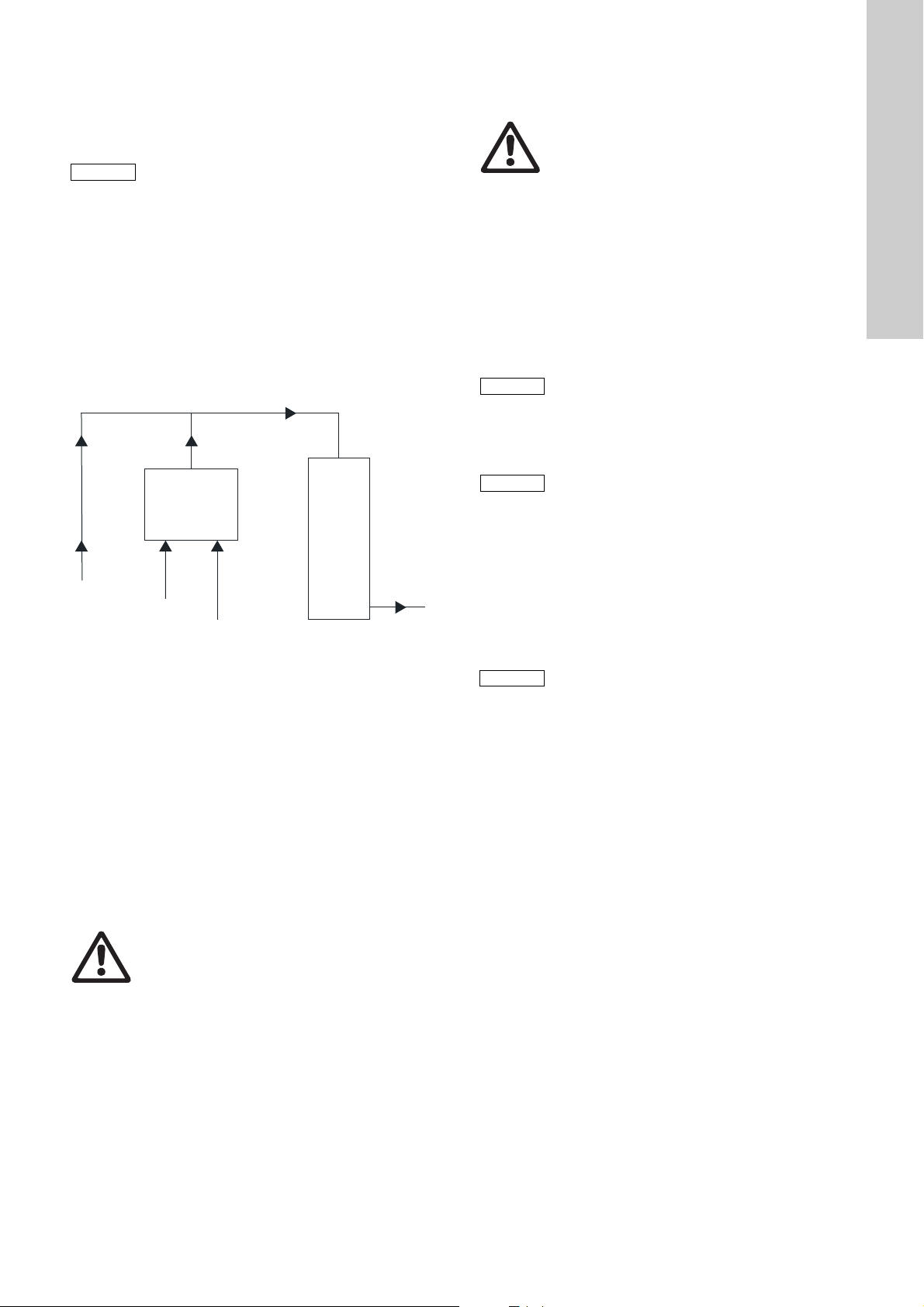
3. Fundamentals
Reactor
Bypass water
NaClO
2
HCl
ClO
2
solution
English (GB)
3.1 Chlorine dioxide for water treatment
Properties of chlorine dioxide
• Strong and fast oxidation and disinfection agent.
• Applications in the treatment of drinking, service, cooling, and
waste water.
• Chemically unstable compound
– Can explosively decompose into chlorine and oxygen when
heated.
– Must be generated on site as required, since storage in
cylinders is not possible.
Advantages of chlorine dioxide compared to chlorine
• Largely good to very good bactericidal, virucidal and sporicidal
effects in the complete pH range of drinking water (pH 6.5 - 9).
The disinfecting effect of chlorine decreases with increasing
pH value.
• No or reduced forming of trihalogen methanes.
• No generation of chloramines with ammonium or amino
compounds.
• Highly reduced potential for generation of organic halogen
compounds of high molecular weight.
• Good stability in water. Long bactericidal and bacteriostatic
protection in the water network.
3.1.1 Preparation of chlorine dioxide
The chlorine dioxide preparation system was specially developed
for the continuous or discontinuous preparation of a chlorine
dioxide solution for water disinfection. The chlorine dioxide is
generated according to the hydrochloric acid/sodium chlorite
procedure in line with the following stoichiometric equation:
5 NaClO
Sodium chlorite + Hydrochloric acid <=> Chlorine dioxide +
Sodium chlorite + Water
This system uses a 7.5 % NaClO
solution in a volume ratio 1:1 for chemical reaction.
The reaction time is approx. 10 minutes. This application uses a
multiple stoichiometric excess of hydrochloric acid for the
following reasons:
• A non-critical chlorine dioxide concentration of 20 g ClO
generated in the reactor.
+ 4 HCl <=> 4 ClO2 + 5 NaCl + 2 H2O
2
Warning
The system must only be operated using a 9 %
hydrochloric acid solution and a 7.5 % sodium
chlorite solution.
Commercially available solutions such as 24.5 %
sodium chlorite or 32 % hydrochloric acid would
generate an explosive concentration, and must
therefore never be used undiluted in the system.
solution and a 9 % HCl
2
2
/l is
3.2 Functional sequence
• Three components are required to generate a chlorine dioxide
solution:
– Hydrochloric acid (HCl)
– Sodium chlorite (NaClO
– Dilution water (bypass).
The added quantities of these components are defined by the
process, and must not be changed. The flows of the individual
components are therefore monitored by flowmeters and flow
controllers.
Hydrochloric acid (9 % solution) and sodium chlorite (7.5 %
solution) are dosed into the reactor with a volume ratio 1:1. There
they react together, and generate an uncritical chlorine dioxide
concentration of 20 g/l.
Following the reactor, the chlorine dioxide solution is diluted by
the bypass water into a solution ready for use.
Fig. 2 Preparation of chlorine dioxide solution
)
2
TM04 8194 4510
Warning
Gaseous chlorine dioxide is explosive above a
concentration of 300 g/m
3
.
• A good yield of chlorine dioxide is achieved with excess acid
of 250-300 %. A further increase in the excess acid only
results in a small improvement in the efficiency.
• Excess acid shifts the equilibrium of the disproportionation
reaction between hydrochloric acid and sodium chlorite to the
right, resulting in an optimum yield.
8
Page 9

4. Design and function
PAPA
4.1 Design of the system
English (GB)
TM04 8196 4510
Fig. 4 Reactor with components, assembled on the back of
the supporting frame
Pos. Description
1 Dosing system for hydrochloric acid (HCl)
1.1 Dosing pump for hydrochloric acid
Suction line with pre-empty and empty signal for HCl
1.2
(red)
1.3 Dosing controller for HCl flow monitoring
2 Dosing system for sodium chlorite (NaClO
2.1 Dosing pump NaClO
Suction line with pre-empty and empty signal for NaClO
2.2
(blue)
2.3 Dosing controller for NaClO
2
flow monitoring
2
)
2
2
3 Bypass water feed pipe
TM04 8195 4510
Fig. 3 Complete system with components, assembled on a
supporting frame
3.1 Solenoid valve (optional circulating pump)
3.2 Impeller counter (flowmeter for bypass water)
3.3 Non-return valve
3.4 Flow limiter
4 Reactor
4.1 Reactor housing
4.2 Reactor valves
5 Post-mixer
6 Connection for ClO
solution line to the injection unit
2
7 Connection for bypass water
8 Controller with display
9 Injector for exhaust device (option)
9
Page 10

4.2 Components
Note
English (GB)
4.2.1 Suction lines
The suction lines must be matched to the tank size and the
system performance (diameter of suction line). They have a dual
level-control unit.
If the level of the components (HCl/NaClO
) drops to the first
2
stage ("Min" contact/pre-empty signal), the alarm "HCl- MIN" or
"NaClO
the controller display. The system remains in operation, the relay
"pre-empty signal NaClO
MIN" is output. This is indicated by flashing of a LED on
2
/HCl" is activated.
2
The system is switched off when the second stage is reached
("Min"-"Min"contact/empty signal), and the alarm "HCl empty
signal" or "NaClO
empty signal" is displayed, the "Alarm" is
2
activated and the alarm LED lights up red permanently.
If a buzzer is connected to the potential-free output relay,
an audible signal is output.
4.2.2 Dosing pumps
The dosing pumps are mounted at the supporting frame.
They operate according to the pulse/pause procedure. The stroke
length is adjusted with a rotary knob. The stroke length is preset,
but may have to be corrected following gauging of the pumps
since the local pressure conditions depend on the application.
The dosing pumps for the systems OCD-164-30 to OCD-164-220
are delivered with an integral gauging system. Gauging of the
dosing pumps for the systems OCD-164-350 to OCD-164-2000 is
carried out using calibration cylinders on the suction side.
Refer to the table 2.1.1 Performance and consumption data for
the dosing rate to be set for the pumps.
The dosing rates of the pumps should be set approximately the
same (± 10-15 %) to guarantee uniform consumption of the
chemicals.
The stroke length must not be adjusted any further following
gauging.
4.2.3 Dosing controller
The dosing controllers guarantee that both chemicals flow into
the system during operation. If the volume flow of one of the
chemicals drops by more than 25-30 %, the dosing controller
outputs an alarm and switches off the system.
The working point must be correctly set to guarantee safe
functioning of the dosing controller, see section 7. Commissioning.
A correctly set working point is indicated by the flashing LEDs on
the controller flowchart, see section 6.2 Control and display
elements.
4.2.4 Reactor
The reactor is installed at the rear of the supporting frame.
The non-return valves on the reactor inlet and outlet must be
selected depending on the system pressure. Standard valves are
suitable for a system pressure of less than 3 bar.
4.2.5 Bypass
The bypass water line dilutes the chlorine dioxide solution
generated in the reactor (approx. 20 g/l) and routes it to the main
water flow. Several versions of the bypass line are available:
• Bypass with solenoid valve and flow limiter
• Bypass with circulation pump
• Bypass with solenoid valve and dosing ball valve (batch mode)
• Bypass for external booster pump (and load unit), see section
10.9 Bypass for external booster pump.
The water in the bypass is monitored by a flowmeter.
The flowmeter switches the system off, if the bypass water falls
below a minimum flow; the LED on the flowchart flashes.
The LED lights up permanently, if the water flow is above the
minimum quantity, see section 6.2 Control and display elements.
Fit a particle filter upstream, if the bypass water is not
free of solids.
4.2.6 Post-mixer
The chlorine dioxide solution is mixed with the bypass water in
the post-mixer (standard).
4.2.7 Options
Power Supply
• 230 V, 50/60 Hz
• 115 V, 50/60 Hz.
Bypass
• Bypass with pump 230 V, 50/60 Hz
• Bypass with pump 115 V, 60 Hz
• Bypass with solenoid valve 230 V, 50/60 Hz and flow limiter
(standard)
• Bypass with solenoid valve 115 V, 50/60 Hz and flow limiter
• Bypass for external booster pump, see section 10.9 Bypass for
external booster pump.
Suction lines
• Suction line 1.3 m for 30/60-litre tank (standard)
• Suction line 2.5 m for 30/60-litre tank
• Suction line 2.5 m for 200-litre tank.
Exhaust device
• Exhaust device, DN 20, 230 V 50/60 Hz (standard)
• Exhaust device, DN 20, 115 V 50/60 Hz
• Without exhaust device.
Reactor non-return valves
• System pressure less than 3 bar (standard)
• System pressure more than 3 bar.
Bus systems
• Profibus DP module
• Ethernet TCP/IP module.
Interface
• RS-232 interface
• RS-422 and RS-485 interface.
4.3 Mode of operation of the system
Positions in brackets, see fig. 4.
When the system is started in normal mode, the solenoid valve
(3.1) opens. Dilution water flows to the post-mixer (5), the flow is
controlled via the impeller counter (3.2).
The two dosing pumps simultaneously pass 9 % hydrochloric acid
and 7.5 % sodium chlorite solution with a ratio of 1:1 into the
reactor (4). The flow quantities of the chemicals are monitored by
the dosing controllers (1.3 and 2.3).
The reaction between sodium chlorite and hydrochloric acid results
in a chlorine dioxide solution with a concentration of 20 g/l in the
reactor (4). The dwell time in the reactor is approx. 10 minutes.
In the subsequent mixer, this solution is diluted down to a
concentration of max. 3.3 g ClO
and performance setting, and passed on to the injection unit.
The system is switched off immediately, if one of the dosing
controllers or the impeller counters detects a low flow.
Warning
Chlorine dioxide is a toxic gas, hydrochloric acid and
sodium chlorite are highly corrosive chemicals which
must be handled properly.
Installation and operating personnel must therefore
be acquainted with the regulations concerning the
handling of chlorine dioxide, hydrochloric acid and
sodium chlorite.
In Germany, the accident prevention regulations UVV
are applicable.
/l, depending on the system size
2
10
Page 11
Note
A set of warning signs for the chlorine dioxide system
Bypass water
Reactor
ClO
2
solution
ClO
2
HCl
NaClO
2
Note
Note
Caution
in accordance with the specifications is available
under Order No 96727022 (515-662).
Please find further general information for operation
of a chlorine dioxide system in:
– Accident prevention regulations "Chlorination of
water" (VGB 65 or GUV 8.15)
– Directive on dangerous working materials
– DIN 938 "Sodium chlorite solution for water
treatment; technical conditions of delivery"
– DIN 939 "Hydrochloric acid for water treatment"
– "Chlorine dioxide for water treatment" DVGW
directive, worksheet W 224 (German)
4.3.1 How the system operates in batch mode
In batch mode, a defined ClO
(batch container), and transported to the injection units by means
solution is added to a holding tank
2
of dosing pumps.
The ClO
3.3 g/l.
concentration can be adjusted within a range of 0.5 to
2
Fig. 5 Preparation of chlorine dioxide solution
For a concentration between 2 and 3.3 g/l, the quantity of bypass
water is set via a dosing ball valve. In the case of concentrations
below 2 g/l, the required quantity of bypass water for a 2 g/l
solution is set. The desired concentration inside the solution
container is then achieved by regulating the two dosing pumps.
The limits for the bypass water quantity are -50 % and +20 % of
the target value. If the target value is undershot (up to -50 %), the
system will automatically regulate the dosing flow of the chemical
pumps for the current water quantity. This is achieved by means
of a pulse-pause control on the dosing pumps. When the water
quantity target value is undershot, the overall performance of the
system is reduced by up to -50 %.
This control makes it possible to compensate pressure
fluctuations in the bypass pipe.
Warning
Protection units should be provided in addition, such
as separate collecting trays for the hydrochloric acid
and sodium chlorite tanks.
Protective clothing for operators has to be provided.
Furthermore, the specified warning signs, danger
information and first aid information must be
positioned at the specified points.
5. Installation
5.1 Transport and storage
Warning
Only transport the system, when it's empty, observe
the weight.
Only use suitable lifting and transport equipment.
• Transport system carefully.
• Dry, cool storage location.
• Protect from direct sunlight.
5.2 Unpacking
• The system is tested at the factory and ready for connection.
• Check for damage, do not install or connect a damaged
system!
• When unpacking, look for loosely packed components.
• Install as soon a spossible following unpacking.
Retain packaging material, of dispose of according to
local regulations.
5.3 Installation location
The applicable local or country-specific regulations
must be observed when selecting and designing the
installation location for the chlorine dioxide system.
In Germany, the accident prevention regulations UVV
are applicable.
The installation location for the system must fulfil the following
requirements:
• The permissible ambient temperature of +5 to +40 °C must be
guaranteed.
• The installation location must be vibration-free and isolated
TM04 8197 4510
fireproof from other rooms.
Reference to the dangers when using the chlorine
dioxide system and to the relevant precautionary
measures must be provided using appropriate signs
at access points to the system rooms and to the
associated chemical storage rooms.
English (GB)
11
Page 12

5.4 Installation scheme
Note
Note
Note
Caution
L
1D&O2
+&O
English (GB)
Select or set a contact water meter in such a way
that, at max. installation output, the control pulses
are not < 5 pulses/sec. Calculation of the contacts
see section 7.3.3 Contact input.
The control for the system can process a max. rate of
50 pulses/sec. If a value greater than 50 pulses/sec.
is calculated, use a different contact water meter.
If the pressure at the injection unit is < 1 bar,
a pressure loading valve must be installed.
A pressure loading valve may not be used in
installations with an internal centrifugal pump, as this
pump only generates an increase in pressure of
approx. 5 mWC.
For the dosing pumps DMI with Plus3 system, ensure
that the container is always underneath the dosing
pump, and the suction line is positioned in a
downwards direction, so that the chemicals can
easily flow back via the return pipe into the container.
Recommended L = min. 200 mm, see fig. 6.
TM04 8199 4510
Fig. 7 System with solenoid valve, installation scheme
Pos. Description
1 Supporting frame
2 Electronics
3 Connection for dilution water
4 Connection for solution line to the injection unit
5 Suction line for HCl dosing pump
TM04 8198 4510
Fig. 6 Installation scheme with suction line length
5.4.1 System with solenoid valve
The systemis delivered as a standard with a solenoid valve in the
dilution water line. In this version, the supply of dilution water and
the addition of chlorine dioxide solution are not carried out in the
same water circuit.
Requirements
• 10 bar > water pressure > 1 bar.
• The counterpressure at the connection of the solution line
should be at least 0.5 bar less than the inlet pressure of the
dilution water.
With the chlorine dioxide solution line shut off (at the
outlet) and an input pressure of more than 10 bar in
the dilution water line (at the inlet), there is a danger
that the system will be damaged.
The solution line must therefore be provided with an
excess pressure valve set to 10 bar.
7 Main water pipe (supplied by the customer)
Isolating valve for the injection unit (supplied by the
8
customer)
9 Sample extraction (supplied by the customer)
10 Non-return valve (supplied by the customer)
Isolating valve for dilution water extraction (supplied by
11
the customer)
Supporting frame exhaust device, with solenoid valve
12
(option)
13 Solution tank with level control (option)
14 External booster pump (option)
15 Load unit for the external booster pump
Pressure loading valve (supplied by the customer), if the
16
system pressure is < 1 bar
Inductive flowmeter (4-20 mA) or contact water meter for
17
proportional control of the system (observe the contacts
from the contact water meter).
6 Suction line for NaClO
dosing pump
2
12
Page 13
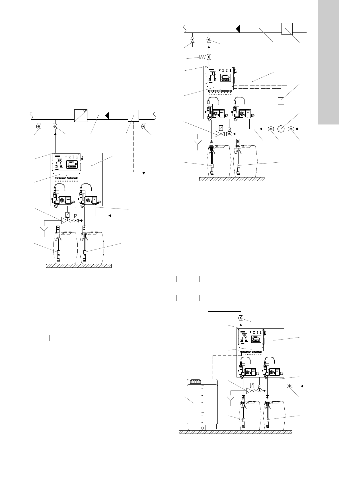
5.4.2 System with internal bypass pump
Note
1D&O2
+&O
Note
Note
1D&O2
+&O
1D&O2
+&O
As an option, the system can be delivered with an internal bypass
pump instead of the solenoid valve. This version is required for
treating closed water circuits, i.e. the sampling of dilution water
and the addition of chlorine dioxide solution are present in the
same water circuit.
The bypass pump is only designed for compensation of the
internal friction losses of the system, and for counteracting the
pressure losses of approx. 0.1 bar in the solution line to the
injection unit.
The solution line to the injector should therefore be kept as short
as possible. The geodetic difference in height between the
connection of the solution line and the injection unit must not
exceed 1 m.
English (GB)
TM04 8201 4510
Fig. 9 System with booster pump, installation scheme
Fig. 8 System with bypass pump, installation scheme
5.4.3 System with external booster pump and load unit
An external booster pump can be connected to the dilution water
line as a further option. This version is required, if sampling of the
dilution water and addition of the chlorine dioxide solution are not
in the same water circuit, and the system pressure at the injector
is higher than the pressure of the dilution water supply line. In this
version, a load unit is required in addition, and is controlled
directly by the system electronics, see fig. 42.
Booster pump and load unit must be selected
separately (see section 11. Accessories).
5.4.4 System with solenoid valve/ball valve (batch tank)
As a further option, the dilution water line can also be selected
with a solenoid valve and dosing ball valve.
This version is required if batch mode is present, i. e. a certain
concentration of ClO
is prepared in a tank. Dosing of the ClO2
2
solution to the injection unit is carried out using dosing pumps.
The concentration of the ClO
adjusted from 2 to 3.3 g/l.
solution in the tank can be
2
The set pressure must be adjusted to the local conditions during
startup. The pressure retention valve must be set such that
siphoning does not take place through emptying of the solution
line when the system is switched off.
TM04 8200 4510
If the pressure set on the loading valve is too high, it
may occur that the required quantity of bypass water
cannot be correctly set.
If the bypass water is not free from solids, a dirt filter
should be installed upstream.
TM04 8202 4510
Fig. 10 System with solenoid valve and ball valve
13
Page 14

5.5 Wall mounting
Caution
Note
Caution
%$
English (GB)
• The mounting material includes screws, wall plugs, washers
and nuts.
• Mount the supporting frame on the wall using the enclosed
mounting material. Select the mounting height such that the
containers with chemicals can be located underneath, and that
the controller display is easy to read. Drilling scheme see
section 2.1.5 Dimensions.
• The liquid level of the containers when full with chemicals
should always be below the dosing pumps.
The system must be freely accessible on the left and
right for maintenance work (approx. 50-60 cm
space).
The mounting material also contains a M6x20
countersunk screw for fixing a gas sensor, see
section 11. Accessories, underneath the reactor.
5.6 Hydraulic connection
Warning
Before hydraulic connection, disconnect the system
from the mains.
It must be possible to insert the suction lines (items 5 and 6) for
hydrochloric acid and sodium chlorite into the tanks without
tension.
• Install the suction hose, return hose and the two empty alarm
cables of the suction line in the tank such that the bottom end
of the suction line is approx. 1 cm above the base of the tank.
5.6.1 Bypass
• In the case of the version with solenoid valve, provide the
dilution water supply line with an isolating valve, and route the
remaining part of the line up to the inlet connection in PVC
tube, and connect.
• In the case of the version with internal bypass pump, route the
dilution water line in a PVC tube as directly as possible from
the main water line up to the inlet connection. Provide a
sampling shut-off valve on the main water line.
Warning
If the sampling line and the solution line are
connected to the same water circuit, a non-return
valve must be fitted in the main line between the
dilution water sampling point and the injector in order
to prevent circulation of the solution with dangerous
building up of chlorine dioxide.
• Route chlorine dioxide solution line to the injection unit in PVC
tube. An isolating valve should also be fitted in this line directly
upstream of the injection unit.
5.6.2 Safety exhaust device (option)
1. Mount the safety exhaust device underneath the system
cabinet.
2. Cut the supplied PE hose to length, and connect to the
diaphragm check valve of the suction injector and to the
associated screwed gland of the supporting frame (in the
centre of the base).
3. Route the injector motive water line in PVC tube of DN 20,
and connect to the solenoid valve. Route the disposal line in
PVC tube of DN 20, and connect to the outlet connection of
the suction injector.
4. Insert the plug of the control voltage cable into the solenoid
valve socket and tighten the plug screw.
The motive water of the suction injector must be free
from sand and suspended matter. It is therefore
recommendable to install a dirt trap upstream of the
solenoid valve.
TM04 8203 4510
Fig. 11 Safety exhaust device, installation scheme
Pos. Description
1 Disposal pipe (waste water/untreated water) DN 20
2 Suction injector
3 Solenoid valve
4 Pressure reducer
5 Water supply line
6 Booster pump
Connection - version A
This connection option is used if the pressure in the water line is
> 4 bar, and there is an adequate total quantity of water (bypass
water and motive water for the suction injector).
If the pressure is > 5 bar, there should be a pressure reducer (4)
installed, so that the pressure upstream of the suction injection is
between 4 and 5 bar.
Connection - version B
This connection option is used if the pressure in the water line is
> 4 bar, i.e. the prescribed pressure upstream of the suction
injection must be generated via a booster pump (6). If there is an
adequate volume of water in the supply line (5) (sufficient water
for the bypass and suction injector), the booster pump (6) can be
connected to the water supply line (5).
The water supply to the booster pump (6) can be conducted via a
separate water supply line at any time.
14
Page 15

5.7 Electrical connection
Caution
Note
A direct connection of the system to the power supply is made
using the terminals 1 (L1), 2 (N) and 3 (PE). Depending on the
Warning
The electrical connection must only be carried out by
qualified personnel.
Observe the local safety regulations!
Switch off the power supply before connecting the
mains cable.
version, the power supply can be 230 V (AC) or 115 V (AC).
Connection to an incorrect power supply may destroy
the system.
Make the electrical connection according to the
enclosed connection diagram.
5.7.1 Terminal connection diagram
Fig. 12 Terminal connection diagram
5.7.2 Power supply
L N PE Description L N PE Description
1 2 3 Power input 16 17 18
4 5 6 Power output 19 20 21
-------------------------------------------
7 8 9 ------------------- 22 23 24 Solenoid valve/pump/bypass water
10 11 12 HCl dosing pump 25 26 27
13 14 15 NaClO
dosing pump 28 29 30
2
Solenoid valve: enclosure exhaust
device
Solenoid valve: exhaust device for
batch tank
English (GB)
TM04 8204 4510
5.7.3 Potential-free outputs
Root NO Description Function
31 33 Fault 31/33 open in case of fault
32 34 Pre-empty signal HCl/NaClO
2
32/34 open in case of pre-empty signal
37 39 Automatic 37/39 closed in case of "system active"
38 40 Tank run dry 38/40 open in case of dry run
5.7.4 Inputs +8 V
+8 V GND IN Description
59 (brown) 60 61 (blue) Dosing controller NaClO
63 (brown) 64 62 (blue) Dosing controller HCl
65 66 67 ------------------------------
69 (brown) 70 (white) 68 (green) Bypass water impeller counter
2
15
Page 16

5.7.5 Inputs +12 V
English (GB)
+12 V GND IN Description Function
43 ------- 44 Batch tank ClO
45 ------- 46 Batch tank ClO
47 ------- 48 Batch tank ClO
49 ------- 50 Batch tank ClO
51 (brown) ------- 52 (white) Pre-empty signal NaClO
------- ------- 53 (green) Empty signal NaClO
------- ------- 54 (green) Empty signal HCl
55 (brown) ------- 56 (white) Pre-empty signal HCl
57 ------- 58 ----------------------------------71 (white) 72 (brown) 73 (green) Hall sensor NaClO
75 (white) 76 (brown) 74 (green) Hall sensor HCl pump
77 (white) 78 (brown) 79 (green)
83 - 84 Contact input water meter
85 - 86 Remote on/off Contact open: "Remote off"
87 - 88 Fault gas warning device Contact open: fault
89 - 90 Contact main water min. Contact open: min. contact main water
-8180
-----------------------------------
overflow
2
max.
2
min.
2
dry run
2
pump
2
NC
Contact open in case of overflow
level above contact
ClO
2
NO contact
Contact closed in case of "Max"
level above contact
ClO
2
NO contact
Contact open in case of "Min"
level below contact
ClO
2
NO contact
Contact open in case of dry run
level below contact
ClO
2
NC
2
Contact open in case of pre-empty signal
level below contact
NaClO
2
NC
2
Contact open in case of empty signal
level below contact
NaClO
2
NC
Contact open in case of empty signal
HCl level below contact
NC
Contact open in case of pre-empty signal
HCl level below contact
-----------------------------------------
5.7.6 Analog signals
Shield IN/OUT Description
95 93 IN + Analog IN
96 97 OUT + Analog OUT
16
Page 17

5.7.7 Profibus/Ethernet (option)
'39
'3*1'
5['7['3
5['7['1
3*1'
576
The controller can be optionally equipped with Profibus or
Ethernet.
Profibus-DP module
The Profibus-DP connection is made via a 6-pin plug.
5.8 Interfaces RS-232, -422 and -485
The controller can optionally be equipped with interfaces.
5.8.1 Connection of RS-232 interface
English (GB)
Fig. 13 Profibus connection diagram
Plug Signal Description
0 RTS (CNTR-P/RTS) Control signal for repeater
1 PGND Shield/protective earth
2 RxD/TxD-N
3 RxD/TxD-P
4 DP GND Ground to DP 5 V
5DP 5 V
CNTR-N Control signal for repeater
Ethernet TCP/IP
• Ethernet 10 Base-T/100 Base-TX (10/100 MBit/s).
• Transport protocol TCP or UDP connection.
• The connection is made using an RJ 45 plug of category 5.
Received data/transmitted data
Negative
Received data/transmitted data
Positive
5 V supply for terminating
resistors
TM04 8205 4510
Fig. 14 Connection diagram of RS-232 interface
5.8.2 Connection of RS-422 and -485 interfaces
Fig. 15 Connection diagram of RS-422 and-485 interfaces
TM04 8206 4510TM04 8207 4510
17
Page 18

6. Operation of control electronics
Automatic
Manual
operation
Logbook
Main menu
System choice Setup Service mode
Type 1, Type 2,
etc.
System type Language Venting
Batch mode Operation mode
Min. contact
water
Startup mode
Current input Units System choice Test mode
Contact input Current output
Manual control Code function
Target value
external
Reset function
Date/time
Exhaust
enclosure
Program
version
Bypass MIN
time
Auto start
English (GB)
6.1 Program structure
Fig. 16 Program structure
18
TM04 8208 4510
Page 19

6.2 Control and display elements
11
10
15 14 13
12
4
3
5
2
1
678
9
17
18
16
Note
Note
Fig. 17 Controller
Pos. Description
LED for dosing controller NaClO
1
• LED flashes: dosing controller set correctly
LED for NaClO
• LED off: correct level
2
• LED flashes: pre-empty alarm active
• LED on: empty alarm active
LED for bypass water
3
• LED on: bypass water is correct
• LED flashes: bypass water outside tolerance
LED for dosing controller HCl
4
• LED flashes: dosing controller set correctly
LED for HCl tank
• LED off: correct level
5
• LED flashes: pre-empty alarm
• LED on: empty alarm
6 Arrow keys for moving in the menus
Function keys
7
• [F1], [F2], and [F3]: select menu items
• [F4]: [Reset] key
[Enter] key
8
• Confirm inputs
[Escape] key
9
• Cancel or switch over to submenu
10 Display, 4-line
11 Master switch with [Emergency stop] function
LED for alarms
12
• LED on or flashing: present alarm
LED display of operation mode "automatic/manual"
13
• LED flashes: automatic control
LED for remote on/off mode
• LED flashes: remote on/off by min. contact for main
14
water
• LED on: remote on/off by external contact
LED for service mode
15
16
17
18
• LED flashes: system in [Service] menu
LED for alarms on the display
• LED on or flashing: present alarm
LED for connection of display to PLC
• LED on: connection correct
LED display
• LED on: display in operation
tank
2
2
The selection possibilities shown on the display are identified by
the numbers 1, 2, and 3, e. g.:
Main menu
1 Automatic
2 Manual operation
3 Logbook
Menu selection is made using the keys [F1], [F2], [F3], e. g. the
function key [F1] is used to select the menu item list under "1",
etc.
Example
• Press the [F1] key to switch to the menu "Automatic".
• Press the [F2] key to switch to the submenu "Manual
operation".
• Press the [F3] key to select the menu "Logbook".
• Press the [Escape] key to return to the main menu (9).
• Press the [Enter] key to confirm an input (8).
6.3 Automatic mode
TM04 8209 4510
In this operation mode the capacity of the system can be
controlled automatically by incoming signals such as contact
input, current input or Bus control.
In order to operate the system in "Automatic" mode,
it is first necessary to select the system type and the
operation mode, see section 6.6.2 Operation modes.
In "Manual control" mode there is no "Automatic" operation.
"Automatic" operation is activated in the main menu using the
[F1] key, and indicated by flashing on the display.
6.4 Manual operation
This operation mode facilitates the manual input of the dosing
capacity by the display in the modes current input, contact input,
manual control, or Bus control.
In order to operate the system in "Manual" mode, it is
first necessary to select the system type and the
operation mode.
"Manual" operation is activated in the main menu using the [F2]
key, and indicated by flashing on the display.
6.5 Logbook
In the "Logbook" menu, all activated and acknowledged alarm
messages are recorded. The operating hours can also be called
in this menu.
• In the main menu, switch to the "Logbook" submenu using the
[F3] key (Logbook).
Logbook
1 active alarms
2 event list
3 operating hours
• Use the [F1] key to display the alarm messages (if present).
• Use the [F2] key to call all events.
• The alarm messages can be deleted, if necessary.
Switching to page 2 is possible using the [ARROW RIGHT]
key, the buffer can be deleted using the [F1] key. Switching to
page 1 is possible using the [ARROW LEFT] key.
• Use the [F3] key to display the operating hours.
Scroll in the respective menu using the [UP] and [DOWN] arrow
keys.
English (GB)
19
Page 20

6.6 System choice
Note
Note
Note
Note
Note
Note
English (GB)
Define the system size and the operation mode in the "System
choice" menu.
The input can be cancelled at any time using the [Escape] key.
The activated system type or the activated mode is displayed
flashing on the display.
6.6.1 System type
• Scroll in the main menu using the [ARROW RIGHT] key on
page 2.
• Use the [F1] key to switch to the "System choice" menu.
• In the "System choice" menu, switch to the "System type"
menu using the [F1] key.
• Select the system size using the [F1], [F2] or [F3] keys, scroll if
necessary using the [ARROW RIGHT] or [ARROW LEFT] key.
After selection of the system type, the following message is
displayed:
System type
164-XXXXD
activated
• Use the [Enter] or [Escape] key to return to the "System
choice" menu.
The system is preset in the factory. The selected type
of system is displayed flashing in the "System
choice" menu.
Check this setting for correctness prior to starting up,
or select a new system type.
6.6.2 Operation modes
5 different operation modes can be selected:
• Batch mode
The performance of the system (100 %) is controlled by the
use of a buffer tank.
• Current input
The system performance (2.5 - 100 %) is controlled via an
external current input signal, e. g. 4-20 mA.
• Contact input
The system performance (2.5 - 100 %) is controlled via an
external contact input signal, e. g. from a contact water meter.
Set the contact water meter in such a way that, at
max. performance the control contacts are not < 1
contact/sec.
If, in exceptional cases, this value is < 1, min. 0.25
contacts/sec., the bypass "Min" time must be
increased.
The controller can process a maximum of
47 contacts/sec. If a value greater than
47 contacts/sec. is calculated, use a different contact
water meter.
• Target value external
The system performance (2.5 - 100 %) is controlled via a Bus
system (can only be selected, if a bus system has been
selected in the "Basic settings > Bus" menu).
The mode is factory-set, i.e. the selected mode is
displayed flashing in the "Operation mode" menu.
Check that this mode is correct before
commissioning; if necessary, select a new mode.
The entry of the parameters for current input and
contact input is described in the Section on
"Commissioning".
6.7 Units
Either metric or US units of measurement can be selected on the
system:
Metric units US units
Bypass water [m
3
/h] Bypass water [gal/h]
System capacity [g/h] System capacity [lb/day]
Contact water meter
[contacts/litre]
Contact water meter
[contacts/gal]
6.8 Setup
In the main menu, switch to the "Basic setting" menu using the
[F2] key (scroll if necessary).
6.8.1 Language
• In the "Basic setting" menu, switch to the "Language" menu
using the [F1] key.
• Select language using [ARROW RIGHT] or [ARROW LEFT]
key.
• Confirm using [Enter].
• Use the [Enter] or [Escape] key to return to the "Basic setting"
menu.
6.8.2 Min. contact water
The min. contact in the main water line (on site) switches the
system to standby, if the set minimum main water flow is fallen
below.
• In the "Basic setting" menu, select the "Min. contact water"
menu using the [F2] key.
• Activate or deactivate the function using the [F1] or [F2] key.
Min. contact main water
activated
Use the [Enter] or [Escape] key to return to the "Basic setting"
menu. The selected function is displayed flashing in the "Min.
contact water" menu.
6.8.3 Current output
• In the "Basic setting" menu, select the "Current output" menu
using the [F3] key.
Example
Default quantity of ClO
Main water quantity 30 m
2
0.3 ppm
3
/h
Contact water meter 1 contact/litre
3
Max. system capacity 0.3 ppm x 30 m
Contacts from water
meter
1 contact/litre x 30 m
1000/3600 = 8.33 contact/sec.
/h = 9 g/h
3
/h x
• Manual control
The system performance (0-100 %) is controlled by manual
input.
When "Manual control" is selected, the installation
can only be started in "Manual mode". If the
installation is started in "Automatic mode", an alarm
message is displayed, and the system stops.
20
Current output
ClO
capacity
2
0 % = XX mA
100 % = YY mA
• Press the [F1] key to select the variable input fields.
Switching between the values (0 %; XX mA; 100 %; YY mA) is
also carried out using the [F1] key.
• Enter individual values using the [UP] and [DOWN] keys
(modify numerical values) and the [ARROW LEFT] and
[ARROW RIGHT] keys (change input position).
• Confirm the set values using the [Enter] key. The selected
current output is activated by pressing the [Enter] key again.
Current output
XX - YY mA
activated
• Use the [Enter] or [Escape] key to return to the "Basic setting"
menu.
Page 21

6.8.4 Code function
Note
Note
2 different code functions can be selected:
• Level 1: Operators
Authorisation for the menus "Automatic, "Manual operation",
"Logbook" and "local/remote".
• Level 2: Parameters
unlimited privileges
Level 1 and 2 are set to "0" each. This means
unlimited privileges without password scanning.
The entered codes are reset by entering the number
"1998". Then both levels are reset to "0".
• In the "Basic setting" menu, scroll to page 2 using the
[ARROW RIGHT] key.
• Switch to "Code function" menu using the [F1] key.
Code function
1 Level 1
2 Level 2
Switch to operator selection using [F1] key.
Level 1 operator
Code: 0
• Activate the input field using [F1] key.
• Enter code (max. 4 digits) using the arrow keys [RIGHT],
[LEFT], (UP], and [DOWN].
• Confirm using [Enter] key.
• Use the [Enter] or [Escape] key to return to the "Code
function" menu.
Switch to "Level 2 Parameters" using [F2] key.
• Activate the input field using [F1] key.
• Enter code as described for "Level 1".
• Use the [Enter] or [Escape] key to return to the "Code
function" menu.
• Use [Escape] key again to return to "Basic setting" menu.
6.8.5 Reset function
In the "Basic setting" menu, select the reset function using the
[F2] key, or scroll in the "Basic setting" menu.
Reset function
Code: xxxx
Input password
• Switch to the input field using the [F1] key, enter new code
using the arrow keys [RIGHT], [LEFT], [UP], and [DOWN],
enter code.
Reset code: 6742
• Confirm using [Enter] key.
• Use the [Enter] or [Escape] key to return to the "Basic setting"
menu.
6.8.6 Date/time
In the "Basic setting" menu, select the "Date/time" menu using
the [F3] key.
Time setting
1 Time
2 Date
3 Daylight sav.
Time
• Switch to the "Time" menu using the [F1] key.
Time setting
New Current
XX:YY:ZZ 17.07.02
2 Accept
Use the [F1] key to activate the input fields for hours (XX),
minutes (YY) and seconds (ZZ) (input field flashing). Switch from
hours to minutes or seconds by pressing the [F1] key again.
• Use the [Escape] key to deactivate the input field.
Setting the time
Following activation of the respective input field using the [F1]
key, set the new value using the arrow keys [RIGHT], [LEFT],
[UP], and [DOWN].
• Confirm the new value in each case using the [Enter] key
(input field no longer flashes).
Once all values have been set and confirmed using the [Enter]
key, press the [F2] key (accept) to update the new time.
• Return to the "time setting" menu with the [escape] key,
by pressing the [escape] key once again return to the "setup"
menu.
Setting the date/day of week
• Switch to the "Date setting" menu using the [F2] key.
Date setting
New Current
XX.YY.ZZ 15.05.02
2 Accept
• Switch to the "Day of week" menu using the arrow [RIGHT]
key, and back to the "Date setting" menu using the arrow
[LEFT] key.
Day of week
New Current
XX.YY.ZZ 15.05.02
XX Monday
2 Accept
The setting is made analogous to the time setting, i.e. activate
input fields using the [F1] key, set new value using the arrow keys
[RIGHT], [LEFT], (UP], and [DOWN], and confirm with [Enter].
The new value is updated by pressing the [F2] key (accept).
• Use the [Escape] key to return to the "Time setting" menu.
Daylight saving time
• Switch to the "Daylight saving time" menu using the [F3] key.
Daylight saving time off
Switch <off>
>
• Activate the input field using the [F1] key (input field flashing).
Various settings can be selected using the [UP] and [DOWN]
arrow keys.
Settings
ON Direct switching to daylight saving time
MANUAL Manual entering of daylight saving time
EU Pre-setting of daylight saving time for EU countries
• Confirm the settings using the [Enter] key.
• Use the [Escape] key to return to the "Time setting" menu.
English (GB)
21
Page 22
MANUAL (manual daylight saving time)
Note
English (GB)
• In the "Daylight saving time" menu, switch to the "Manual
daylight saving time" menu using the [RIGHT] arrow key.
In this menu you can redefine the daylight saving time.
• Activate the input field using the [F1] key (input field flashing).
Enter the new values using the arrow keys [RIGHT], [LEFT],
[UP], and [DOWN], and confirm using the [Enter] key.
• Activate the respective input fields by pressing the [F1] key as
often as required.
Following manual setting of the daylight saving time, return to the
"Daylight saving time" menu using the [LEFT] arrow key.
• Activate the input field using the [F1] key, and select "Manual"
setting using the [UP] and [DOWN] keys.
• Confirm new setting using the [Enter] key.
• Use the [Escape] key to return to the "Time setting" menu,
and press again to return to the "Basic setting" menu.
6.8.7 Enclosure exhaust device
The enclosure exhaust device is used to regularly exchange the
air within the supporting frame. The exhaust device is
time-controlled, defined by switch-on and switch-off times.
• In the "Basic setting" menu, scroll using the [RIGHT] and
[LEFT] arrow keys.
• Switch to the "Exhaust enclosure" menu using the [F1] key.
Exhaust enclosure
1 ON/OFF <off>
2 Switch-on time
3 Switch-off time
• Activate or deactivate the injector using the [F1] key.
Switch-on time
• Switch to the "Switch-on time" menu using the [F2] key.
The switch-on time is specified in minutes (0 to 30 minutes).
• Activate the input field using the [F1] key (flashing), enter
numerical value using the [UP] and [DOWN] keys, change the
input point using the arrow [LEFT] and [RIGHT] keys.
• Confirm using [Enter] key.
• Use the [Enter] or [Escape] key to return to the "Exhaust
enclosure" menu.
Switch-off time
• Switch to the "Switch-off time" menu using the [F3] key,
the switch-off time is specified in hours (0 to 24 hours).
The input is made analogous to the input for the "switch-on time".
6.8.8 Bus options
• In the "Basic setting" menu, scroll using the [RIGHT] and
[LEFT] arrow keys.
• Use the [F2] key to switch to the "Bus options" menu.
Bus options
1 Profibus DP
2 Modbus
3 no bus >
For Ethernet, switch to display page 2.
• Select bus system using the [F2] or [F3] key.
• Use the [Enter] and [Escape] key to return to the "Basic
setting" menu.
6.8.9 Program version
• In the "Basic setting" menu, switch to the "Program version"
menu using the [F2] key.
Hardware C16 x_01
Software
SPS: ......
OP: ......
• Use the [Enter] or [Escape] key to return to the "Basic setting"
menu.
• Use the [Escape] key to return to the main menu.
6.8.10 Bypass MIN time
• In the "Basic setting" menu, switch to the "Bypass MIN time"
menu using the [F1] key.
Bypass MIN time
new XXX s
current XXX s
2 Accept
The bypass MIN time is factory-set to 60 seconds.
This time can be adjusted between 20 and
210 seconds.
Changing the bypass MIN time
• Activate the input field using the [F1] key (flashing), enter
numerical value using the [UP] and [DOWN] keys, change the
input point using the arrow [LEFT] and [RIGHT] keys.
• Confirm using [Enter] key.
• Accept the new setting using the [F2] key. The "New" and
"Current" values are now identical.
6.8.11 Auto start
This function is used to perform an automatic system restart.
This is required, if the system’s bypass water supply becomes
compromised as a result of pressure fluctuations (bypass water
undershoots the MIN limit) or if the bypass water overshoots the
MAX limit.
The system will restart automatically following a set pause time.
The number of start attempts (cycles) is configurable.
No. of cycles: 0-10
Pause time: 1-10 minutes
"Automatic start" function is not activated, when the number of
cycles is set to 0.
If the bypass water supply remains compromised after the set
number of cycles has elapsed, an alarm message will be output
("bypass water MIN" or "bypass water MAX").
In the "Basic setting" menu, switch to the "Automatic start" menu.
Auto start
Cycles xxx
Pause time xxx min
2 Accept
22
Page 23

6.8.12 Startup mode
Note
Note
Note
The startup mode is used to fill the reactor with water. The dosing
pumps can be gauged, and the dosing controllers can be
readjusted at the same time.
• In the "Service mode" menu, switch to the "Startup mode"
menu using the [F2] key.
Startup mode
1 Batch concentration
2 Bypass water
3 Start
• Use the [F2] key to switch to the "Bypass water" menu.
2 Bypass water <off>
setpt.: 420 l/h
actual: 0 l/h
1 Limit -xx %/+xxx % >
• Activate or deactivate the bypass using the [F1] key.
The "setpt." value shows what quantity of water is required
(depending on system size). The "actual" value shows the current
water flow, "Limit" defines the minimum and maximum bypass
water quantities.
• Switch to the impeller counter contacts display using the arrow
[RIGHT] key.
Bypass water
Pulses XX.X lmp./s
Water YYY l/h
2 Accept <
Warning
Enter a new quantity of water using the [F1] key only
in case of batch concentration error, see section
9. Maintenance!
If this input is used incorrectly, the factory settings
can be restored using the reset function.
• Use the arrow [LEFT] key to return to the "Bypass water
ON/OFF" menu.
• Use the [Escape] key to return to the "Startup mode" menu.
• Use the [F3] key to switch to the "Startup mode/Start?" menu.
Startup mode
Start?
Use the [Enter] key to start the startup mode (startup time approx.
13 minutes).
Startup mode can be cancelled at any time using the
[Escape] key.
The remaining time during which the system is in startup mode is
output on the display. The system switches off automatically at
the end of the startup time.
Startup mode
finished
6.8.13 Test mode
The Test mode permits checking of current output, relay, display
and LEDs.
Current output
In the "Service mode" menu, switch to the "Test mode" menu
using the [F3] key.
• In the "Test mode" menu, switch to "Test current output" using
the [F1] key.
Check the individual current outputs using the [F1] to [F3] keys.
• Activate the current outputs using the [F1], [F2] and [F3] keys.
• Deactivate using the [Escape] key, returning to the "Test
mode" menu.
Relay
Checking of relays for: NaClO
exhaust system, automatic/manual, error message, pre-empty
pump, HCl pump, bypass,
2
and dry-run.
• Activate using the [F1] to [F3] keys, scrolling if necessary;
Deactivate by pressing the [F1] to [F3] keys again.
• Use the [Escape] key to return to the "Test mode" menu.
Display
• In the "Test mode" menu, switch to the display test using the
[F3] key.
• Set the contrast using the [UP] and [DOWN] keys.
• Activate using the [Enter] key.
• Deactivate using the [Enter] key (press 2x), or the [Escape]
key.
• Use the [Escape] key to return to the "Test mode" menu.
LED
• In the "Test mode" menu, scroll using the arrow [RIGHT] and
[LEFT] keys, and switch over to the LED test using the [F1]
key.
• Activate using the [Enter] key.
• Deactivate using the [Enter] or the [Escape] key.
• Use the [Escape] key to return to the "Service mode" menu or
to the main menu.
6.9 Local/remote
The "local/remote" menu is only displayed, if a bus
system was selected in the "setup/Bus" menu.
• Scroll with the arrow [RIGHT] key in the main menu.
• Use the [F1] key to switch to the "local/remote" menu.
Local/remote
1 local control
2 remote control
Select control mode using the [F1] or [F2] key.
local control/remote control
activated
Use the [Enter] or [Escape] key to return to the main menu.
• Local control: operation and control of the system on site
• Remote control: control of the system via a bus system.
English (GB)
If the Startup mode is cancelled prematurely and
then restarted, the startup time commences again at
approx. 20 minutes.
• Use the [Escape] key to return to the "Service mode" menu.
23
Page 24

7. Commissioning
Note
Note
Note
Note
Note
Note
English (GB)
The system should always be commissioned with
water. To do this, immerse both suction lines into a
tank filled with water.
Commissioning must only be carried out by
authorized specialists.
7.1 Directives
As a result of the applicable accident prevention regulations,
chlorine dioxide systems may only be commissioned when their
correct condition has been checked by a specialist.
The chlorine dioxide systems must be checked by a specialist
each time they are restarted. This test must be repeated every 6
to 12 months according to the regulations.
Only persons who have been appropriately trained may be
commissioned with operation and maintenance of the chlorine
dioxide systems and the handling of chemicals.
Commissioning must only be carried out by trained specialists
using appropriate instructions.
7.2 System choice
Define the system size and the operation mode in the "System
choice" menu.
• The input can be cancelled at any time using the [Escape] key.
• Use the arrow [right] key in the main menu to switch to page 2
in the display.
Main menu <
1 System choice
2 Basic settings
3 Service mode >
• Use the [F1] key to switch to the "System choice" menu.
System choice
1 System type
2 Operation mode
• In the "System choice" menu, switch to the "System type"
menu using the [F1] key.
• Press [F1], [F2] or [F3] to select the system size. If necessary,
scroll to the left or right using the arrow keys.
The preset system size is displayed flashing;
if necessary select a new size.
Once the system type has been selected, the following message
appears on the display:
System type
OCD-164-XXXD
activated
• Use the [Enter] or [Escape] key to return to the "System
choice" menu.
7.3 Selection of operation mode
The chlorine dioxide system can be operated in four different
modes:
• Batch mode
• Current input
• Contact input
• Manual control
• Target value external
The preset mode is displayed flashing; if necessary
select a new mode.
When "Manual control" is selected, the installation
can only be started in "Manual mode". If the
installation is started in "Automatic mode", an alarm
message is displayed, and the system stops.
Main menu
Main menu
1 Automatic
2 Manual operation
3 Logbook >
• Switching to page 2 is possible using the arrow [RIGHT] key.
Display page 2
Main menu <
1 System choice
2 Basic settings
3 Service mode >
• Use the [F1] key to switch to the "System choice" menu.
System choice
1 System type
2 Operation mode
• Use the [F2] key to switch to the "Operation mode" menu.
Display page 1
Operation mode
1 Batch mode
2 Current input
3 Contact input >
If necessary, use the arrow key to scroll to page 2.
Display page 2
Operation mode
1 Manual control
2 Target value ext.
The "Target value ext." menu option is only visible if a
bus system has been selected in the "Basic
settings/bus options" menu.
24
Page 25

7.3.1 Batch mode
Note
Note
Note
Note
Note
Activating the operation mode "Others"
• In the "Operation mode" menu, switch to the "Others" menu
using the [F1] key.
Batch mode
activated
• Use the [Enter] and [Escape] key to return to the "System
choice" menu.
Ensure that the level contacts of the batch containers
are connected and correctly set up. Faulty settings
may result in error messages in the batch mode.
Setting the concentration
• Use the [Escape] key to switch to the "Main menu", display
page 2.
Main menu <
1 System choice
2 Basic settings
3 Service mode >
• Use the [F3] key to switch to the "Service mode" menu.
Service mode
1 Venting
2 Startup mode
3 Test mode
• In the "Service mode" menu, switch to the "Startup mode"
menu using the [F2] key.
Startup mode
1 Batch concentration
2 Bypass water
3 Start
• Use the [F1] key to switch to the "Batch concentration" menu.
Batch concentration
3.0 g/l ClO
2
The default batch concentration is 3.0 g/l.
• Any concentration in the range of 2 to 3.3 g/l ClO
entered.
can be
2
• Press the [F1] key to select the concentration input field.
• Enter the value by pressing the [UP] or [DOWN] buttons
(to change the number) and the [LEFT] and [RIGHT] arrow
buttons (to change the input position).
• Press the [Enter] key to confirm the entry.
• Use the [Enter] and [Escape] key to return to the "Startup
mode" menu.
7.3.2 Current input
• In the "Operation mode" menu, switch to the "Current input"
menu using the [F2] key.
Selection
[F1] key 0-20 mA
[F2] key 4-20 mA
[F3] key Others
When selecting the [F1] (0-20 mA) key, for example, the display
shows:
Current input
added 0.00 ppm
Max. flow H
0000.0 m
The quantity (ppm) of ClO
3
/hb >
added, and the max. flow in the main
2
O
2
water line are entered in this menu.
The value for the amount of ClO2 added is a "starting
value", which does not necessarily have to
correspond to a ClO
the system, because the control calculation is unable
measurement downstream of
2
to factor in consumption in the solution line.
• Switch to the variable field "0.00" using the [F1] key.
• Use the [UP] and [DOWN] keys to change the numerical
value, and the arrow [LEFT] and [RIGHT] keys to change the
input field.
• Enter the value to be added.
• Use the [F1] key to switch to the variable field "Max. flow H
and enter the max. volume of water.
2
O"
• Confirm using [Enter] key.
• Use the [Enter] key again to switch to the menu:
Current input <
0 g/h = 0 mA
9 g/h = 20 mA
The requisite system capacity is now calculated here, relative to
the amount to be added (ppm) and the existing max. flow rate of
H
O.
2
Example:
Default quantity of ClO
Main water quantity: 30 m
Max. system capacity: 0.3 ppm x 30 m
: 0.3 ppm
2
3
/h
3
/h = 9 g/h
If the calculated system capacity is greater than the
size of the system, only the max. possible system
capacity (e.g. 10 g/h) can be dosed.
• Use the [Enter] key to switch to the menu:
Current input <
Flow of H
Max xxx.x m
Min xxx.x m
O0 mA
2
3
/h
3
/h
The max. and min. volume of water, which can be supplied with
through the set quantity to be added (ppm), and the
ClO
2
installation size are specified in this menu. The system switches
off below the min. water quantity (system capacity < 2.5 %).
• Activate the operation mode using the [Enter] key.
Current input
0-20 mA
activated
• Use the [Enter] key to return to the "Operation mode" menu.
• Press the [Escape] key twice to return to the main menu.
Analogous procedure for "4-20 mA" and the "Others" current
input.
In the case of the "Others" current input, current input signals
between 0 and 20 mA can be variably set.
Basic load setting
Current input <
0 g/h = 0 mA
9 g/h = 20 mA
Use the [F1] key to switch to the variable field 0 g/h, and set a
basic load.
The basic load depends on the system type. It is
bigger than 2.5 % of the system capacity.
For example, for the system type OCD-164-1000 the
basic load is bigger than 0.25 g/h.
English (GB)
25
Page 26

7.3.3 Contact input
Note
Note
Note
Note
Note
Note
English (GB)
In the "System choice" menu, switch to the "Contact input" menu
using the [F3] key.
Contact input
Max. flow of H
0000.0 m
O
2
3
/h >
The max. flow in the main water line are entered in this menu.
• Use the [F1] key to switch to the variable field "0000.0 m
and enter the max. flow rate. Enter using the [UP], [DOWN],
[LEFT], [RIGHT] arrow keys analogous to the "Current input"
entry.
• Confirm using [Enter] key.
• Use the [Enter] or [RIGHT] arrow key to switch to the menu:
Contact input <
added 0.00 ppm
Water meter
00.000 pulses/litre >
The quantity (ppm) of ClO
contact water meter are entered in this menu.
added and the pulses/litre of the
2
• Switch to the variable field "0.00" using the [F1] key.
• Use the [UP] and [DOWN] keys to change the numerical
value, and the arrow [LEFT] and [RIGHT] keys to change the
input field.
• Enter the value to be added.
• Use the [F1] key to switch to the variable field "water meter
00.000", and enter the contacts of the existing contact water
meter.
• Confirm using [Enter] key.
The control for the system can process a max. rate of
50 pulses/sec. If a value greater than 50 pulses/sec.
is calculated, use a different contact water meter.
• Use the [Enter] or [RIGHT] arrow key to switch to the menu:
Contact input <
0 g/h = 0.00 pulses/sec.
9 g/h = 8.33 pulses/sec.
The requisite system capacity, as well as the pulses output by the
water meter are now calculated in this menu.
Example:
Default quantity of ClO
Main water quantity: 30 m
: 0.3 ppm
2
3
/h
Contact water meter: 1 pulse/litre
Max. system capacity: 0.3 ppm x 30 m
Water meter:
1 pulse/litre x 30 m
8.33 pulses/sec.
3
/h = 9 g/h
3
Select or set the contact water meter in such a way
that, at max. system capacity, at least 5 pulses/sec.
are transmitted to the controller.
• Use the [Enter] key to switch to the menu:
Contact input <
Flow of H
Max. xxx.x m
Min. xxx.x m
O
2
3
/h
3
/h
The max. and min. volume of water, which can be supplied with
through the set quantity to be added (ppm), and the system
ClO
2
size, are specified in this menu. The system switches off below
the min. water quantity (system capacity < 2.5 %).
3
/h",
/h x 1000/3600 =
1. Confirm using [Enter] key.
Contact input
activated
2. Use the [Enter] key to return to the "Operation mode" menu.
3. Press the [Escape] key twice to return to the main menu.
The preset water flow rate in the "contact or current
input" mode is [m
3
/h].
Use the [F1] key to select other displayed units: [l/s]
and [%].
Basic load setting
Contact input <
0 g/h = 0.00 pulses/sec.
9 g/h = 8.33 pulses/sec.
Use the [F1] key to switch to the variable field 0 g/h, and set a
basic load.
The basic load depends on the system type. It is
bigger than 2.5 % of the system capacity.
For example, for the system type OCD-164-1000 the
basic load is bigger than 0.25 g/h.
7.3.4 Manual control
• Scroll with the arrow [RIGHT] key in the "Operation mode"
menu.
Display page 2
Operation mode <
1 Manual control
2 Target value ext.
• Select the "Manual control" mode using the [F1] key.
Manual control
activated
• Use the [Enter] and [Escape] key to return to the "Operation
mode" menu.
When "Manual control" is selected, the installation
can only be started in manual mode.
7.3.5 Target value external
• Scroll with the arrow [RIGHT] key in the "Operation mode"
menu.
Display (page 2)
Operation mode <
1 Manual control
2 Target value ext.
The "Target value ext." menu option is only visible, if
a bus system has been selected in the "Basic
settings/bus options" menu.
• Select the "Bus control" mode using the [F2] key.
Target value external
activated
• Use the [Enter] and [Escape] key to return to the "Operation
mode" menu.
26
Page 27

7.4 Venting of the bypass line
Note
Caution
Caution
Note
Note
In order to ensure that the installations work properly, the bypass
water line must be vented each time it is commissioned.
• In the main menu, switch to the "Service mode" menu using
the [F3] key. If necessary, use the arrow keys [RIGHT] and
(LEFT] to scroll.
Service mode
1 Venting
2 Startup mode
3 Test mode
• Use the [F1] key to switch to the "Venting" menu.
Venting
1 Bypass <off>
2 HCl pump <off>
3 NaClO
• Use the [F1] key to activate the bypass line (solenoid valve or
bypass pump).
"Bypass <ON>" appears on the display. The bypass line can now
be vented.
7.4.1 Bypass pump (option)
Use the [F1] key to activate or deactivate the bypass, i.e. the
solenoid valve or the bypass pump.
• Turn the vent screw on the front of the pump motor
counter-clockwise, and unscrew it fully using a spanner.
• After venting, refit and tighten the vent screw (1).
Use the [F1] key to switch the bypass off again; the current
status, "Bypass <OFF>", appears on the display.
The bypass pump only works and vents correctly, if
the bypass water at the suction connection of the
pump is at a pressure of at least 0.05 bar (0.5 m
WC).
pump <off>
2
7.4.2 Venting of the dosing pumps (HCl and NaClO
)
2
Fig. 19 Venting the pumps
The procedure for both dosing pumps is identical
Before the dosing pump is switched on, the dosing medium
should be sucked through the overflow hose (3) by the pump with
the aid of the syringe, which is included. Insert the syringe onto
the overflow hose (3) at the end of the suction line, and carefully
draw the dosing medium through the pump until the pre-chamber
is filled with water. Open the spindle (4) (normal operation).
Commission the dosing pumps using the [F2] (HCl pump) and
[F3] (NaClO
pump) keys. As long as the respective keys are
2
pressed, the pumps remain switched on. The display shows e.g.
"HCl pump <ON>".
The pumps are switched off when the buttons are released.
The display shows e.g. "HCl pump <OFF>".
Both dosing pumps must be vented.
• Open the dosing head venting spindle (1) by turning it
counter-clockwise.
• Switch on the dosing pumps using the [F2] or [F3] keys.
• Set the stroke adjustment knob to 90-100 %.
• Close the venting spindle once dosing medium flows back into
the tank bubble-free out of the vent hose (2).
• If the venting process is not performed correctly or if it is
interrupted, briefly close and re-open the vent screw (1)
repeatedly (max. 1 turn).
English (GB)
TM04 8210 4511
The dosing pump is completely vented, if the LED for
dosing controller monitoring flashes evenly.
If the stroke setting changes during venting,
the preset stroke length must be re-adjusted
following the venting process.
Fig. 18 Bypass pump with vent screw (1)
TM04 8210 4510
• The pumps are switched off when the buttons are released.
27
Page 28
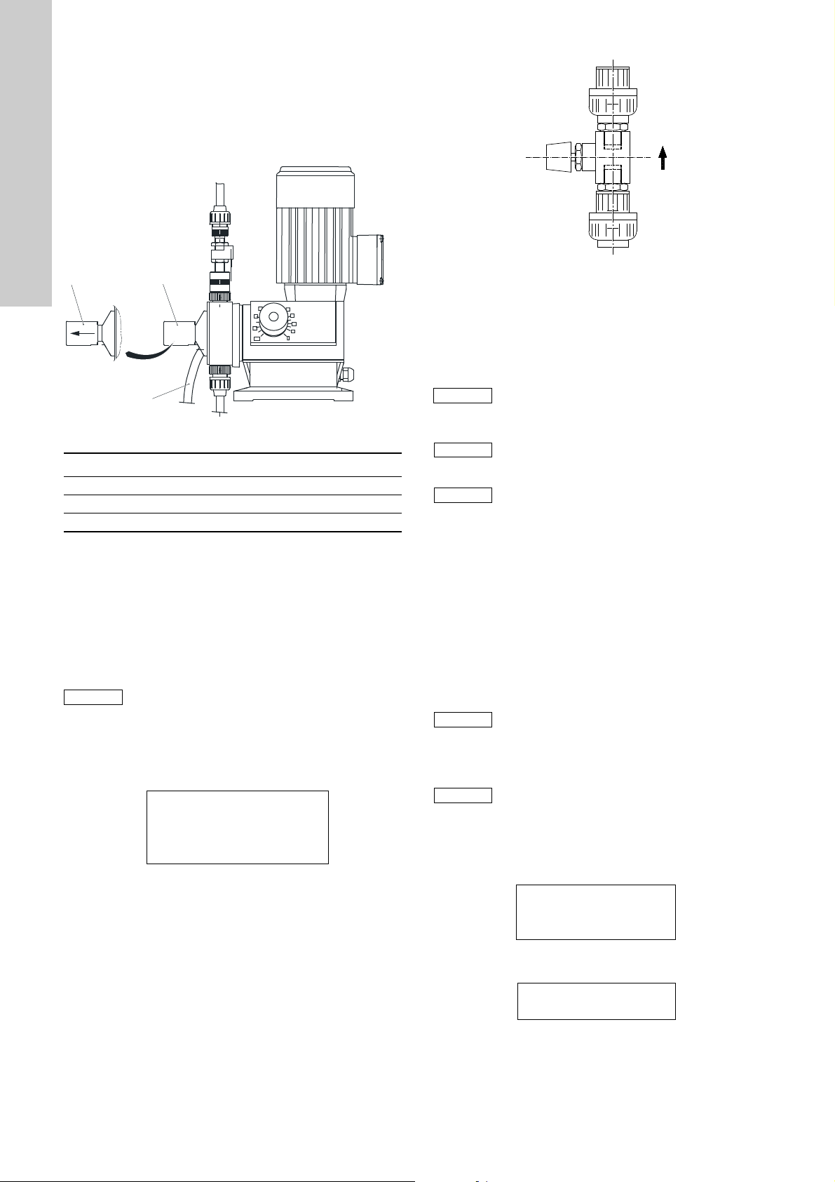
7.4.3 Dosing pumps for the systems OCD-164-350 to
Note
90
100
0
80
70
40
20
10
30
Caution
Note
Note
Note
Note
English (GB)
OCD-164-2000
With the system sizes OCD-164-350 to OCD-164-2000, dosing
pumps with integral pressure relief and vent valves are used.
The pressure relief valve protects the complete pressure side of
the dosing line system from an impermissibly high buildup of
pressure.
Fig. 20 System with pressure relief and vent valve
Pos. Description
1 "Venting" position
2 "Operation" position
3 Venting hose
The pressure relief valve can be opened manually, thus serving
as a vent valve at the same time.
• Rotate the knob such that the smaller cut-out is positioned on
the nub of the dosing head (1). The rotary knob is then further
away from the dosing head, and the valve spring is relieved.
• Switch on the dosing pumps using the [F2] or [F3] keys.
• Return the rotary knob to the "Operation" position (2) when
dosing medium flows out of the venting hose (3) back into the
tank without bubbles.
The dosing pump is completely vented, if the LED for
dosing controller monitoring flashes evenly.
• The pumps are switched off when the buttons are released.
• Use the [Escape] key to return to the "Service mode" menu.
Setting the bypass water quantity for batch operation
• Use the [F2] key to switch to the "Bypass water" menu.
2 Bypass water <off>
target XXX l/h
actual: YYY l/h
1 limit: - 50 %/+ 20 %
The target value is calculated and displayed on the basis of the
entered concentration and size of the system. In this menu, the
bypass water (actual value) must be set to the required amount of
water (target value).
Fig. 21 Setting the bypass water quantity at the ball valve
To change the water quantity use the ball valve at the back of the
system.
• Use the [F2] key to switch on the bypass water (solenoid
valve). Use the dosing ball valve to match the actual value to
the target value.
Open the ball valve carefully, and adjust actual value
to target value from bottom direction. If the ball valve
TM04 8212 4510
is opened too far, the actual value can be displayed
wrongly.
If the actual flow is changed, the changed flow is
displayed correctly after approx. 8-10 seconds.
If it is difficult to set the water amount using the ball
valve, slightly loosen both screws on the valve. Set
the water amount, and then retighten the screws.
Check the tightness of the ball valve.
• Use the [F2] key to switch off the bypass water again.
Changing the limit
• Use the [F1] key to switch to the input field -50/+20 %.
• Enter the value by pressing the [UP] or [DOWN] keys
(to change the number), and the [LEFT] and [RIGHT] arrow
keys (to change the input position).
Switching from -50 % to +20 % is carried out using the [F1] key.
• Press the [Enter] key to confirm the entry.
• Use the [Escape] key to return to the "Startup mode" menu.
Due to the processing of the signals by the SPS
control (PLC), the displayed bypass water quantity
may vary slightly.
This is not significant, because the variations are
always within a certain range.
The bypass water must later be checked again in
automatic mode or in manual mode, as the pressure
conditions in the system may change as a result of
further operation of the dosing pumps.
Starting of startup mode
• Use the [F3] key to switch to the "Startup mode/start" menu.
• Press the [Enter] key to start the startup mode.
Startup mode
activated
Runtime xxx s
The remaining time for the startup mode is shown on the display.
If it has expired, the system switches off automatically.
TM04 8213 4510
28
Startup mode
finished
• Use the [Enter] or [Escape] key to return to the "Startup"
menu.
• Use the [Escape] key to return to the "Service mode" menu or
to the "Main menu".
Page 29

7.4.4 "Current input, Contact input, Manual control, Target
Caution
Note
value ext." modes
Checking the bypass water
• In the main menu, scroll to page 2 using the [ARROW RIGHT]
key.
• Switch to the "Service mode" menu using the [F3] key.
• In the "Service mode" menu, switch to the "Startup mode"
menu using the [F2] key.
Display with startup mode
Startup mode
2 Bypass water
3 Start
• Use the [F2] key to switch to the "Bypass water" menu.
2 Bypass water <off>
target XXX l/h
actual: YYY l/h
1 limit: -XX/+600 %
• Use the [F2] key to switch on the bypass water (solenoid valve
or bypass pump).
The target value is defined by the system choice. The actual
value shows the current water quantity flowing through the
bypass.
Starting of startup mode
• Use the [F3] key to switch to the "Startup/start" menu.
• Press the [Enter] key to start the startup mode.
Startup mode
activated
Runtime xxx s
The remaining time for the startup mode is shown on the display.
If it has expired, the system switches off automatically.
Startup mode
finished
• Use the [Enter] and [Escape] key to return to the "Startup mode"
menu.
• Use the [Escape] key to return to the "Service mode" menu or to
the "Main menu".
7.5 Calibrating the dosing pumps
Details of the dosing rate required for the size of
installation in question can be found in the table in
2.1.1 Performance and consumption data under
"Consumption of components".
As diluted chemicals are used in these installations,
the consumption data may be compared 1:1 with
water.
Calibration can be done with water.
The dosing pumps with double head system can also
be calibrated at any time in regular mode without
interrupting the process sequence.
Fig. 22 Calibrating the dosing pump
Warning
Don't let the calibration tube run empty.
Re-open the isolating valve in good time.
• Shut the isolating valve (4) at the calibration tube (5).
The supply from the tank is now interrupted. The calibration
tube is slowly emptied.
• Using a stopwatch, time how long it takes for the dosing
volume of 0 to 10 ml (10-ml measuring glass) and of 0 to 5 ml
(5-ml measuring glass).
• Open the isolating valve (4) at the calibration tube (5).
• Calculate the dosing flow:
10-ml measuring glass: V (l/h) = 36/t (s)
5-ml measuring glass: V (l/h) = 18/t (s)
If the calibrated dosing volume deviates from the target value
(table), the dosing rate is corrected with the stroke adjustment
button (on the dosing pump) and checked once again.
If a pump deviation occurs, use the stroke adjustment button to
re-adjust it and re-calibrate it.
Consumption of components, see table in section
2.1.1 Performance and consumption data.
If several calibration attempts are made, ensure that the suction
lines do not become filled with air. If necessary, deaerate the
pump again.
English (GB)
TM04 8211 4510
29
Page 30

Dosing pumps for the systems OCD-164-220 to
English (GB)
OCD-164-2000
1. Calibration is made using calibration cylinders.
2. Fill both calibration cylinders with water up to a certain mark.
3. Place the suction lines into the calibration cylinders.
4. Use a stopwatch to determine the time required to dose a
particular quantity of liquid.
5. Remove the suction lines from the calibration cylinders, read
off the new value, and calculate the dosing performance.
6. If the calibrated dosing volume deviates from the setpoint
(table), the dosing rate is corrected with the stroke adjustment
button (on the dosing pump) and checked once again.
Consumption of components, see table in section
2.1.1 Performance and consumption data.
7. If a pump deviation occurs, use the stroke adjustment button
to re-adjust it and re-calibrate it.
If several calibration attempts are made, ensure that the suction
lines do not become filled with air. If necessary, deaerate the
pump again.
Consumption of components, see table in section
2.1.1 Performance and consumption data.
7.6 Adjusting the dosing controllers
The dosing controllers can be adjusted during startup mode.
Consumption of components, see table in section
2.1.1 Performance and consumption data.
Fig. 23 Dosing controller
Pos. Description
1 Clamping nut
2 Adjusting screw
3Sensor
The dosing controllers are correctly set, if the LEDs on the
controller flowchart flash regularly, see section 6.2 Control and
display elements, items 1 and 4.
If the LEDs are off, the dosing controllers are set too high. If the
LEDs flash very rapidly (or light up permanently), the dosing
controllers are set too low.
Adjustment
1. Loosen the clamping nut (1).
2. Readjust the sensor using the adjusting screw (2).
3. If the LED is off, the sensor is set too high.
4. Adjust the sensor from above to the correct working point,
until the LED flashes regularly.
5. Adjust the sensor about approx. 1 mm lower with the
adjustment screw (2).
6. Fix the sensor using the clamping nut (1).
TM04 8215 4510
30
Page 31
8. Operation of the system
Note
Note
Note
Note
Note
Before the system is started, the system size and
operation mode must be selected.
Independent from the operation mode, the menu structure
remains the same, the only difference is in the display of the
prevailing signals, i.e. current input in mA, contact input in 1/s and
manual mode in %.
Main menu
Main menu
1 Automatic
2 Manual operation
3 Logbook >
8.1 Automatic operation
In "Manual control" mode, automatic operation is
impossible.
8.1.1 Current input/contact input
• In the main menu, switch to the "Automatic > start" menu using
the [F1] key.
Auto: x.x/y.y Start?
Dosing xxx %
Bypass xxx l/h
ClO
2
Depending on the mode setting, the x.x/y.y field indicates the
prevailing current signal in mA or the prevailing contacts
(contact water meter) in 1/s.
• Activate or deactivate the system using the [Enter] key.
The display changes from "start?" to "active" or from "active"
to "start?". The display shows the most important information
about the operation of the system. Further information, such
as levels, dosing pumps and bypass water, can be obtained by
scrolling with the arrow keys to the pages 2 and 3.
Display page 2
Auto: start? <
1 Level
3 Logbook >
Level
• Use the [F1] key to switch to the "Level" menu.
Level
HCl: MIN - MAX
: MIN - MAX
NaClO
2
• Use the [Escape] key to return.
On page 2, scroll on with the arrow keys:
Display page 3
Auto: Start? <
1 Dosing pumps
2 Bypass >
x.x g/h >
Dosing pump
• Use the [F1] key to switch to the "Dosing pumps" menu.
NaClO2H = X D = Y
HCl H = X D = Y
The Hall sensor signals and the signals from the flow
controllers can be checked in this menu.
The values displayed here are not identical to the
dosing stroke details from the individual dosing
pumps, e.g. 120 strokes/min, because the calculation
does not relate to 1 minute.
The default value changes as the installation runtime
progresses, whereby the following evaluation is decisive.
H = X: Hall sensor signals
D = X: flow controller signals.
D = H
Each of the Hall sensor signals from the dosing
pump is fed back by the flow controller.
More flow controller signals are fed back, i.e. if the
D > H
deviation is too large, this reduces the precision of
the flow monitor, although the system keeps running
(there is no error message).
Too few dosing controller signals are fed back, the
D < H
system goes into malfunction mode. The dosing
controller settings have to be checked.
The installation is correctly set at D = H whereby a
few extra dosing controller signals (D > H) have no
bearing on the precision of the system.
• Use the [Escape] key to return.
Bypass water
• Use the [F2] key to switch to the "Bypass water" menu.
Bypass water <off>
setpt.: xxx l/h
actual: xxx l/h
1 limit: -XX/+600 %
The target and actual value for the bypass water can be
checked in this menu. The limits can also be changed in this
menu.
Changing the limit
• Use the [F1] key to switch to the input field -XX or +600 %
• Enter the value by pressing the [UP] or [DOWN] keys (to
change the number), and the [LEFT] and [RIGHT] arrow keys
(to change the input position).
• Switching from -XX to +600 or from +600 to -XX is carried out
using the [F1] key.
• Press the [Enter] key to confirm the entry.
• Use the [Escape] key to return.
If a new system size is set, the preset limits for the
new system are loaded.
English (GB)
31
Page 32

8.1.2 Batch mode
Note
Note
Note
Note
English (GB)
• In the main menu, switch to the "Automatic start" menu using
the [F1] key.
Display page 1
Auto: Start?
Dosing: xxx %
Bypass: xxx l/h
: x,x g/h >
ClO
2
The x.x field shows the set batch concentration.
• Activate or deactivate the system using the [Enter] key.
The display changes from "start?" to "active", or from "active"
to "start?". The display shows the most important information
about the operation of the system.
Further information, such as levels, dosing pumps and bypass
water, can be obtained by scrolling with the arrow keys to the
pages 2 and 3.
Display page 2
Auto: Start? <
1 Level
>
Level
• Use the [F1] key to switch to the "Level" menu.
Level
HCl: MIN - MAX
:MIN - MAX
NaClO
2
:MIN - MAX
ClO
2
• Use the [Escape] key to return.
On page 2, scroll on with the arrow keys:
Display page 3
Bypass water
Use the [F2] key to switch to the "Bypass water" menu.
Bypass water <off>
setpt.: XXX l/h
actual: YYY l/h
1 limit: - 50 %/+ 20 %
The target and actual value for the bypass water can be
checked in this menu. The limits can also be changed in this
menu.
Changing the limit
• Use the [F1] key to switch to the input field -50 or +20 %
• Enter the value by pressing the [UP] or [DOWN] keys (to
change the number), and the [LEFT] and [RIGHT] arrow keys
(to change the input position).
• Switching from -XX to +50 or from +20 % to -XX is carried out
using the [F1] key.
• Press the [Enter] key to confirm the entry.
• Use the [Escape] key to return.
If a new system size is set, the preset limits for the
new system are loaded.
In batch mode, the limit values for the bypass water
can only be changed within the range ± 20 %.
Changing the batch concentration
See section 7.3.1 Batch mode, setting the concentration
Auto: Start? <
1 Dosing pumps
2 Bypass
Dosing pump
• Use the [F1] key to switch to the "Dosing pumps" menu.
NaClO
H = X D = Y
2
HCl H = X D = Y
The Hall sensor signals and the signals from the flow
controllers can be checked in this menu.
H = X: Hall sensor signals
D = X: flow controller signals.
The values displayed here are not identical to the
dosing stroke details from the individual dosing
pumps, e.g. 120 strokes/min, because the calculation
does not relate to 1 minute.
The default value changes as the installation runtime
progresses, whereby the following evaluation is decisive.
D = H
Each of the Hall sensor signals from the dosing
pump is fed back by the flow controller.
More flow controller signals are fed back, i.e. if the
D > H
deviation is too large, this reduces the precision of
the flow monitor, although the system keeps running
(there is no error message).
Too few dosing controller signals are fed back,
D < H
the system goes into malfunction mode. The dosing
controller settings have to be checked.
The installation is correctly set at D = H whereby a
few extra dosing controller signals (D > H) have no
bearing on the precision of the system.
• Use the [Escape] key to return.
32
Page 33
8.1.3 Target value external
Note
Note
Note
Note
Note
Note
System capacity control and processing the input and output
signals via the bus system.
• Select the bus system used in the "Basic Settings/Bus
Options" menu, see section 6.8.8 Bus options.
• Activate the bus control in the "Operation mode" (page 2).
Scroll with the arrow [RIGHT] key in the "Operation mode"
menu. Select the "Bus control" mode using the [F2] key.
Target value external
activated
• Use the [Enter] and [Escape] key to return to the main menu.
Display page 1
Main menu
1 Automatic
2 Manual operation
3 Logbook >
• Switch to page 3 using the arrow [RIGHT] key.
Main menu <
1 local/remote
The "local/remote" menu is only displayed, if a bus
system was selected in the "Basic settings/Bus
options" menu.
• Use the [F1] key to switch to the "local/remote" menu.
Local/remote
1 local control
2 remote control
• Select control mode using the [F1] or [F2] key.
local control/remote control
activated
• Use the [Enter] or [Escape] key to return to the main menu.
Local control
Operation and control of the installation on-site, by manual entry
of the installation capacity in % terms in "Manual" mode.
Remote control
Control of the installation via the bus system in "Automatic"
mode.
Auto: x.x % Start?
Dosing: xxx %
Bypass: xxx l/h
: x.x g/h >
ClO
2
8.2 Manual operation
Irrespective of the selected mode, the system can
only be activated in "Manual" mode if the installation
capacity has been set manually in %.
Given the pulse pause control of the dosing pumps
for HCl and NaClO
2.5 % are not possible.
A dosing capacity set on the display less than 2.5 %
leads to dosing of 0 %.
A dosing capacity set on the display more than 95 %
leads to a dosing capacity of 100 %.
• In the main menu, switch to the "Manual > start?" menu using
the [F1] key.
Manual: x.x % Start?
Dosing: xxx %
Bypass: xxx l/h
ClO
2
The input field "x.x" shows the dosing capacity setting in %.
Setting the dosing capacity
• Select the input field "x.x" using the [F1] key.
• Use the [UP] and [DOWN] keys to change the numerical
value, and the arrow [LEFT] and [RIGHT] keys to change the
input field. Dosing capacity range from 0 to 100 %.
• Confirm entry using [Enter] key.
• Activate or deactivate the system using the [Enter] key.
The display changes from "start?" to "active", or from "active"
to "start?". The display shows the most important information
about the operation of the system. Further information,
such as levels, dosing pumps and bypass water, can be
obtained by scrolling with the arrow keys to the pages 2 and 3.
The display pages 2 and 3 (levels, dosing pump,
bypass) are analog to automatic operation,
see section 8.1 Automatic operation.
8.2.1 Manual mode for batch
The operation and functions are the same as in
automatic mode, except the solution container is not
continually filled between the contacts MIN and MAX
as in automatic operation, but rather is only filled
once up to the MAX contact. Then the system shuts
down.
In manual mode, the system does not automatically
switch on when the MIN contact in the solution
container is reached.
dosing capacity ranges under
2
: x.x g/h >
English (GB)
33
Page 34

8.3 Faults
English (GB)
Fault Cause Remedy
1. During venting of the
dosing pumps, the suction
line does not fill with liquid,
despite 100 % setting
2. LED for the bypass water
flashes when the
installation is started.
There is too little or no
dilution water flowing
through the bypass line
3. Startup mode is
automatically interrupted
4. The dosing pumps are not
dosing, or the LEDs for the
flow monitor are not
flashing
5. Imprecise dosing pump
capacity
6. Alarm signal: only manual
mode
7. System is started, display
indicates "active", but does
not dose or the bypass
water is not flowing
8. Alarm signal:
"Dosing controller HCl" or
"Dosing controller NaClO
a) The venting spindle in the dosing head is
incorrectly set
b) Suction and pressure valves in the dosing
head have dried out, making them leak slightly
c) Leaks between the lower end of the suction
line and the connection nipple on the floater
switch foot valve
a) No dilution water available
b) The coil in the solenoid valve is defective,
the valve remains closed
c) The counterpressure at the injection unit is too
high
d) The admission pressure of the solenoid valve
is too low
e) The bypass pump has not been correctly
vented
f) Isolation valve upstream of the system and/or
in the chlorine dioxide solution line to the
injection unit is closed
g) Flow meter operation impaired by
contaminated dilution water
a) The water tank is empty
b) The float switch in the suction line is stuck
c) The float switch is defective
d) Air in the suction line or in the dosing head of
the pump
a) Air in the suction line
b) Injection unit is blocked
c) The suction or discharge valves are not
correctly fitted
a) The dosing head has not been correctly vented
b) Counterpressure fluctuations
c) Suction and discharge valves are dirty
a) "Manual" mode has been selected, although
the system has been started in automatic mode
a) Remote ON/OFF active, i.e. the system has
been set to standby via this contact
b) Min. contact main water active, i.e. the volume
of main water is too low
a) Air in the suction line
b) No liquid in the pump calibration system, the
2
"
isolation valve on the calibration tube is closed
c) Diaphragm or pressure sensor in the flow
controller are defective
a) Open the venting spindle by approx. 1 turn;
if necessary, open or close it further
b) Remove the suction and pressure valves,
dip them in clean water and shake them;
Screw them back in and vent the pump again
c) Remove the suction line from the container,
check that the suction hose is positioned
correctly on the nipple, correct it if necessary
and vent it once again
a) Check the dilution water supply line
b) Replace the coil
c) Reduce the counterpressure at the injection
unit, or possibly increase the admission
pressure (max. 10 bar)
d) Increase the admission pressure (min. 1 bar)
e) Vent the bypass pump again
f) Open the isolation valve
g) Remove the flow meter and clean it in clean
water
a) Refill the water tank
b) Check the float switch, clean it, if necessary
c) Exchange the float switch
d) Vent the dosing pumps again
a) Vent the suction line and dosing head with
the dosing pump set to 100 % dosing
capacity
b) Open the injection unit isolation valve or
reduce the counterpressure at the injection
unit
c) The suction and pressure valves in the
dosing head must be installed in such a way
that the flow direction arrow points upwards
a) Repeat the venting process
b) Install a pressure loading valve downstream
of the Oxiperm system
c) Clean the valves
a) Acknowledge the alarm and start the system
in manual mode
a) Switch remote ON/OFF to ON
b) Increase the main water volume or deactivate
the min. contact
a) Vent the suction line and dosing head with
the dosing pump set to 100 % dosing
capacity
b) Open the isolation valve and vent the pump
c) Check the flow controller
34
Page 35

8.4 Error messages of the controller
No. Fault Cause Remedy
1
Pre-empty signal
2 HCl HCl level in tank too low
3
Empty signal
4 HCl HCl tank empty
5 Dosing controller NaClO
NaClO
NaClO
2
2
2
6 Dosing controller HCl
7 Level "Max-Max" Solution tank: ClO
8 Level "Min-Min" Solution tank: ClO
Flow
9
Bypass water
Flow
10
Bypass water
"Min" Bypass water too low Increase flow of bypass water
"Max" Bypass water too high Reduce flow of bypass water
11 Fault gas warning device Gas alarm Eliminate leakage
12 ------------------------ ----------------------------------- -------------------------------------13 Open-circuit at current output Cable broken Replace cable
14
Hall sensor
defective
16 H2O
17
HCl
2
24 VDC, too large Controller defective Check controller
18 24 VDC, too small Fuse SI 12 defective Replace fuse
19 15 VDC, too large Controller defective Check controller
20 15 VDC, too small Fuse SI 9 defective Replace fuse
21 -15 VDC, too large Controller defective Check controller
22 -15 VDC, too small Fuse SI 9 defective Replace fuse
Voltage
23 8 VDC, too large Controller defective Check controller
24 8 VDC, too small Fuse SI 11 defective Replace fuse
25 12 VDC, too large Controller defective Check controller
26 12 VDC, too small Fuse SI 11 defective, inputs overloaded Replace fuse, check connection
27 -12 VDC, too large Controller defective Check controller
28 -12 VDC, too small Fuse SI 11 defective Replace fuse
29 Reactor temperature too high Dilution water too low, H
30 Reactor temperature rise too high Dilution water too low, H
31 Battery in PLC exhausted Battery exhausted Replace battery
32 Dosing controller H
Preliminary H
33
tank
O
2
O
2
"Max-Max"
34 Flow HCl min Dosing quantity too low
35 Flow HCl max Dosing quantity too high
36 Flow NaClO
37 Flow NaClO
38 Flow H
39 Flow H
40 Fault level ClO
min Dosing quantity too low
2
max Dosing quantity too high
2
O Dilution min. Dosing quantity too low
2
O Dilution max. Dosing quantity too high
2
2
41 Fault level HCl
2
43 Fault level H2O
44 Open-circuit in temperature sensor Temperature sensor defective Replace sensor
45 Short-circuit Short-circuit Check controller
46 Fault bypass water flow Leakage in solenoid valve Replace solenoid valve
47 Fault: only manual mode possible
NaClO2 level in tank too low
NaClO2 tank empty
Dosing controller incorrectly set
Dosing controller defective
overflow level reached Check "Max" contact
2
dry-run level reached
2
Cable broken, component defective Exchange cable or component15 NaClO
O pump defective
2
O pump defective
2
Dosing controller incorrectly set, dosing
controller defective
Overflow level in preliminary tank for H
reached
O is
2
Level switch on solution tank defective
Level switch of suction line defective42 Fault level NaClO
"Manual" mode has been selected, although
the system has been started in automatic
mode
Refill tank
Readjust controller
Replace controller
Check "Min" contact
Check dosing quantity of the pump
Check system status "ON/OFF"
Check H
O setting of the pump,
2
replace pump
Readjust controller
Replace controller
Check float switch in tank
Check dosing pump or quantity
Check level switch
When "Manual control" is selected,
start the system in manual mode
English (GB)
35
Page 36

English (GB)
6,
6, 6, 6,
6,
6,
6,
6,
6,
6,
6,
6,
6,
Note
8.5 Fuses and LEDs of the controller
Fig. 24 Dosing controller
Pos. Description Ampere
Backup fuse, solenoid valve, system
SI 1
drain
Backup fuse, solenoid valve, H
SI 2
rinsing
Backup fuse, solenoid valve, bypass
SI 3
water
Backup fuse, NaClO
SI 4
dosing pump
(NaClO2/HCl)
2
O
2
SI 5 Backup fuse, HCl dosing pump 6.3 A
SI 6 Backup fuse, H
Backup fuse, solenoid valve, enclosure
SI 7
exhaust
Backup fuse, solenoid valve, exhaust
SI 8
device, preliminary
O dosing pump 6.3 A
2
SI 9 Internal supply voltage ± 15 V 100 mA
SI 10 Main fuse of the system 10 A
SI 19 Internal supply voltage ± 12 V / +8 V 100 mA
SI 12 Internal supply voltage +24 V 2 A
SI 13 Internal supply voltage +5 V 1 A
1 LED (green) - RUN
2 LED (red) - ERROR
3 LED (red) - battery
4 LED (yellow) - WATCHDOG
5 Battery
In the correct operating state, the LED (1) is green, and the
LED (4) is yellow. If there is a fault, e.g. if no more programs are
available or the memory card is defective, the LED (1) is green
and the LED (2) is red.
In this case:
• Turn the controller off and on again. If the error still occurs:
• Switch off the controller, remove the battery, switch the
controller on again. Wait for the program to be loaded from the
memory. Insert the battery again. If the error still occurs:
• Reinstall the program, or change the memory card.
1 A
1 A
1 A
6.3 A
1 A
1 A
Fuse: ∅5 x 20 mm, slow-blow
8.6 Possible faults when changing the tank
Each of the suction lines has a pre-empty and an empty-signal
contact. If the level in the container reaches the "pre-empty
signal" contact, an alarm message appears on the display, yet the
system does not stop.
If the level reaches the "empty signal" contact, an alarm message
appears on the display, and the system shuts down.
Pre-empty signal
A ON ACK 1/1
Pre-empty signal
NaClO
2
23-04-10 14:36:12
The system remains in operation until the empty-signal contact is
activated.
Empty signal
A ON ACK 1/1
Empty signal
TM04 8216 4510
The system switches off automatically.
Change of tank at "pre-empty" alarm
The "pre-empty" alarm appears on the display.
1. Remove the suction line from the tank.
2. The system switches off automatically, the "HCl or NaClO
empty" alarm is displayed.
3. Fit the suction line into the new tank.
4. Press the [F4] key to acknowledge the two alarm messages.
5. Press [Enter] to re-activate the system.
Change of tank at "empty" alarm
The "empty" alarm appears on the display.
1. Remove the suction line from the tank.
2. Fit the suction line into the new tank.
3. Press the [F4] key to acknowledge the two alarm messages.
4. Press [Enter] to re-activate the system.
NaClO
2
23-04-10 14:36:12
Warning
Only use standard tanks.
Never pour the contents of the tank into another one!
There is a great danger of residual chemicals being
poured into the wrong tank.
The procedure is identical for both tanks: If both
tanks are changed, up to 4 alarm messages have to
be acknowledged, before the system can be
re-activated.
2
36
Page 37

9. Maintenance
Note
Note
Warning
Before any maintenance work, i.e. when exchanging
parts and gaskets, the entire system has to be rinsed
with water.
Before maintenance work, all chemicals must be
completely removed!
When handling acids or lyes, wear appropriate
protective clothing.
Maintenance and repair work must only be carried
out by authorized specialists.
According to the German accident prevention
regulations GUV 8.15 and VGB 65 § 19, chlorine
dioxide systems must be regularly checked for
safety, at least once a year and prior to every startup,
by a specialist.
This check can be carried out by the after-sales
servicing department during the six-monthly
maintenance.
9.1 Maintenance of the dosing pumps
A drop in performance of the dosing pumps may be caused by
contamination in the suction and discharge valves.
9.1.1 Dismantling and cleaning the valves
1. Unscrew the suction and discharge valves.
2. Use a pin (∅2) to press out the ball cage, ball and O-ring from
below.
3. Replace damaged parts.
When re-assembling, observe the correct position of the parts,
see fig. 25.
9.1.2 Dismantling the diaphragm
For safety reasons, the dosing diaphragm should be replaced
after a maximum of 2000 operating hours.
1. Insert the suction lines of the pumps into a water tank, and run
the system until the dosing heads of the pumps have been
well purged with water.
2. Open venting screws by one rotation until the venting lines are
also purged. Switch off the system.
3. Loosen the four dosing head screws.
4. Remove the dosing head, and unscrew the diaphragm by
rotating to the left.
Assembly
1. Insert the intermediate ring so that the relief hole points
downwards.
2. Screw in the diaphragm.
3. Switch on the pump briefly until the diaphragm is located at
the rear dead point.
4. Carefully fit the dosing head, and uniformly and gently tighten
the screws in a diagonally opposite sequence, so that the
dosing head is not damaged.
5. Vent the pump.
9.2 Maintenance of the suction lines
The suction lines are equipped with foot valves and filter nuts.
The Reed contacts are integrated in the suction line body.
The floats with magnet core are located axially on the valve body
and are sliding.
The foot valve should be dismantled and cleaned occasionally,
at the latest when the suction performance drops.
The function symbol (NO contact) must be present on the top
surface of the two floats.
If this is not the case, disconnect the float and reverse the
polarity.
English (GB)
Fig. 25 Construction of the valves
Pos. Description
1 Valve body
2 Ball cage
3 Seat
4Ball
5 O-ring
When installing the valves, make sure that the flow
direction is correct (arrow).
The O-ring must be inserted correctly into the
provided groove.
OCD-164 Product No.
-30 to -220 95730320 (553-1995)
-350 to -2000 95730321 (553-1996)
TM04 8217 4510
TM04 8221 4510
Fig. 26 Suction line, spare parts
Pos. Description
1 Float switch, PVC
2Ball
3 Valve seat, grey PVC
4 Filter nut, PVC grey
37
Page 38

9.3 Maintenance of reactor
Note
Note
A
B
C
English (GB)
Warning
Prior to any maintenance work on the reactor, rinse
the system with water until no more chemicals are
present.
Check the valves on the reactor for leaks each time
maintenance work is carried out. Replace valves if
necessary.
For reasons of safety, no spare parts are offered for
reactors, apart from the valves.
In case of faults, the entire reactor must be
exchanged.
9.3.1 Spare valves (3 per reactor)
OCD-164 System pressure Product No.
-30 to -220
-350 to -2000
The reactor valves are not identical to the valves of
the dosing pumps.
Do not interchange the valves!
< 3 bar 91836549 (553-640)
> 3 bar 96689071 (553-641)
< 3 bar 91836550 (553-642)
> 3 bar 96689073 (553-643)
Fig. 27 Reactor with valves
Pos. Description
A
Val veB
C
TM04 8222 4510
38
Page 39

9.4 Maintenance of injector
Caution
The injector consists of nozzle, diffuser and holder with
diaphragm non-return valve.
The sucked-in chlorine dioxide is mixed with the motive water in
the diffuser, and transported to the disposal line.
The diaphragm non-return valve prevents water from penetrating
the PE line when the exhaust device is switched off.
If water containing heavy deposits is used, this can lead to losses
in performance when sucking. The nozzle must be cleaned in this
case. Regularly clean the filter of the dirt trap (if fitted).
Do not use any sharp objects to clean the nozzles.
Hydrochloric acid has proved to be the best cleaning
agent.
Observe the regulations for handling hydrochloric
acid.
English (GB)
Fig. 28 Sectional drawing of injector
Pos. Description Product No. Pos. Description Product No.
10 Diffuser 96681122 (12.6420-3019) 130 Diaphragm 91834695 (12.312-4)
20 Nozzle 96681126 (12.6421-401) 140 Cylinder screw 96687994 (50.1054)
25 Twisting part 96681053 (12.5577-300) 150 Disc 96688017 (50.1326)
30 Base 96681054 (12.5578-200) 155 Hexagon nut 96681142 (12.6583-400)
40 Pressure spring 91836364 (12.2493-400) 160 O-ring 91835590 (52.164)
50 Threaded ring 91834667 (12.175-4) 170 Diaphragm seat 91834700 (12.375-4)
60 Seat 91834662 (12.120-4) 180 O-ring 91835566 (52.125)
70 O-ring 91835573 (52.139) 190 O-ring 91835609 (52.277)
80 Diaphragm ring 91834701 (12.376-4) 200 Plug 96687957 (48.1210)
90 Top part 96681051 (12.5575-310) 210 O-ring 91835574 (52.141)
95 Base part 96681052 (12.5576-210) 220 Union nut 91835736 (53.058-25)
110 Union nut 91834741 (12.561-4) 230 Insert 96688366 (53.056-25)
120 Piston 91834666 (12.171-4) 240 Flat gasket 96681143 (12.6584-410)
TM04 8223 4510
39
Page 40

10. Spare parts kits and spare parts
English (GB)
10.1 DMI dosing pumps with double-head system
OCD-164 Product No.
-30
-120
-220 91835902 (553-1488)
96641420 (553-1486)
Fig. 29 Exploded view of DMI dosing head
Pos. Description
3 Suction/Discharge valve DN 4
4 Venting cartridge
17 Dosing diaphragm
21 Dosing diaphragm
37 Oval-head screw
73 O-ring, Viton
TM04 8218 4510
40
Page 41

10.2 DMI dosing pumps with single-head system
OCD-164 Product No.
-30
-120
-220 96688818 (553-1411-3)
Fig. 30 Exploded view of DMI dosing head
Pos. Description
3 Venting cartridge
7 Dosing diaphragm
11 Flat gasket
13 Suction/Discharge valve DN 4
18 Cylinder screw
19 Disc
11 Flat gasket
96688816 (553-1403-3)
10.3 Dosing pumps DMX 221
OCD-164 Product No.
-350
-700
-1000 91835950 (553-521-3)
-1500 96634413 (553-522)
-2000 91835954 (553-522-3)
91835948 (553-520-3)
10.4 Bypass, post mixer, and dosing controller
Spare parts kits comprise:
• O-rings for bypass line and post-mixer
• Non-return valve, DN 20, for bypass line
• O-rings and flat gaskets for the bypass line
• Spare parts set for dosing controller
OCD-164
-30
-30
-120
-120
-220 With < 3 bar 96689109 (553-745)
-220 Without < 3 bar 91836563 (553-1717)
-220 With > 3 bar 96689110 (553-745.1 )
TM04 8219 4510
-220 Without > 3 bar 96729526 (553-1717.1)
-350 -------
-700 -------
-1000 -------
-1500 -------
-2000 -------
Further spare parts
Description Product No.
Post-mixer 96708931 (12.5861-300)
Pressure loading valve, DN 8 96635200 (525-0567)
Pressure loading valve, DN 20 96376567 (525-1113)
Set of micro-fuses for electronics 96688774 (553-1095)
Discharge hoses for HCl/NaClO
with connection (pump/reactor)
Battery for CR-2032 electronics ------------ ------------
Plus3
system
With < 3 bar 96689088 (553-720)
Without < 3 bar 96729524 (553-1716)
With > 3 bar 96689089 (553-720.1)
Without > 3 bar 96729525 (553-1716.1)
With > 3 bar 96689089 (553-720.1)
Without > 3 bar 96729525 (553-1716.1)
With < 3 bar 96689088 (553-720)
Without < 3 bar 96729524 (553-1716)
System
pressure
< 3 bar 96689090 (553-722)
> 3 bar 96689091 (553-722.1)
< 3 bar 96689092 (553-723)
> 3 bar 96689093 (553-723.1)
< 3 bar 96689094 (553-724)
> 3 bar 96689095 (553-724.1)
< 3 bar 96689096 (553-725)
> 3 bar 96689097 (553-725.1)
< 3 bar 96689098 (553-726)
> 3 bar 96689099 (553-726.1)
Product No.
,
2
91836658 (553-1711)
English (GB)
Fig. 31 Exploded view of DMX 221 dosing head
Pos. Description
1 Dosing diaphragm, PTFE/NBR
2 Shaped gasket, NBR
3 Grooved ring, Perbunan
8 Suction/Discharge valve DN 8
TM04 8219 4510
41
Page 42

10.5 Enclosure exhaust device
English (GB)
Fig. 32 Spare parts for exhaust device
Pos. OCD-164 Description Product No.
-30 to -220
50.1
50.3
50.5
50.6 Screw-in part, DN 20 96688372 (53.057-25)
50.7 Union nut, DN 20 91835736 (53.058-25)
50.8 O-ring 91835574 (52.141)
50.9 Reduction, short, DN 20/DN 15 96688439 (53.183-25-20)
50.10 Connection nipple 96708988 (12.6416-400)
50.11 Solenoid valve, 230 V, 50 Hz 96687772 (45.10245-1/2)
50.12
50.13 Cable gland, M16 x 1.5 96726056 (45.10131)
50.14 Cable gland, M20 x 1.5 96687755 (45.10132)
50.15 PE hose 8/11 96687899 (47.1320008)
50.16 Screw, M6 x 25 96726750 (50.461)
50.18
50.20 -30 to -2000 Knurled nut, M6 95729417 (50.1570)
-350 to -1000 95729412 (12.5999-200)
-1500 to -2000 95729413 (12.5999-210)
-30 to -220
-350 to -2000 96693040 (545-2000-1)
-30 to -2000
-30 to -220
-350 to -1000 95729415 (12.6237-310)
-1500 to -2000 95729416 (12.6237-320)
Lateral part
Injector
Insert, DN 20 96688366 (53.056-25)
Solenoid valve, 115 V, 60 Hz 96687775 (45.10249-1/2)
Connection cable 96708949 (12.6023-420)
Rear wall
95729411 (12.5998-200)
96691986 (545-1000-1)
95729414 (12.6237-300)
TM04 8224 4510
42
Page 43

10.6 Bypass with solenoid valve and flow limiter (standard version: solenoid valve)
'1
'1
Fig. 33 Spare parts for exhaust device
Pos. OCD-164 Description Product No.
30.1
30.2 Union nut, DN 20 91835736 (53.058-25)
30.3 O-ring 91835574 (52.141)
30.4 Screw-in part, DN 20 96688372 (53.057-25)
30.5 Reduction, short 96688439 (53.183-25-20)
30.6 Connection nipple 96688427 (53.095-20-1/2)
30.7
30.11
30.30 Insert, DN 20, G 1/2" IG 96708974 (12.6202-400)
30.31 Flowmeter FHKU 100 91834753 (12.6010-1)
30.32 O-ring 96688273 (52.416)
30.40 Post-mixer 95727697 (12.7136-300)
-30 to -2000
-30 to -350 Solenoid valve 230 V, with flow limiter 8 l/min 95729444 (12.3532-420)
-30 to -350 Solenoid valve 115 V, with flow limiter 8 l/min 95729445 (12.3532-421)
-700 to -2000 Solenoid valve 230 V, with flow limiter 16 l/min 95728307 (12.3532-423)
-700 to -2000 Solenoid valve 115 V, with flow limiter 16 l/min 95729446 (12.3532-424)
-30 to -2000
Screw connection, DN 20 96688360 (53.055-25)
Flat gasket 96728862 (54.027)
English (GB)
TM04 8225 4510
43
Page 44
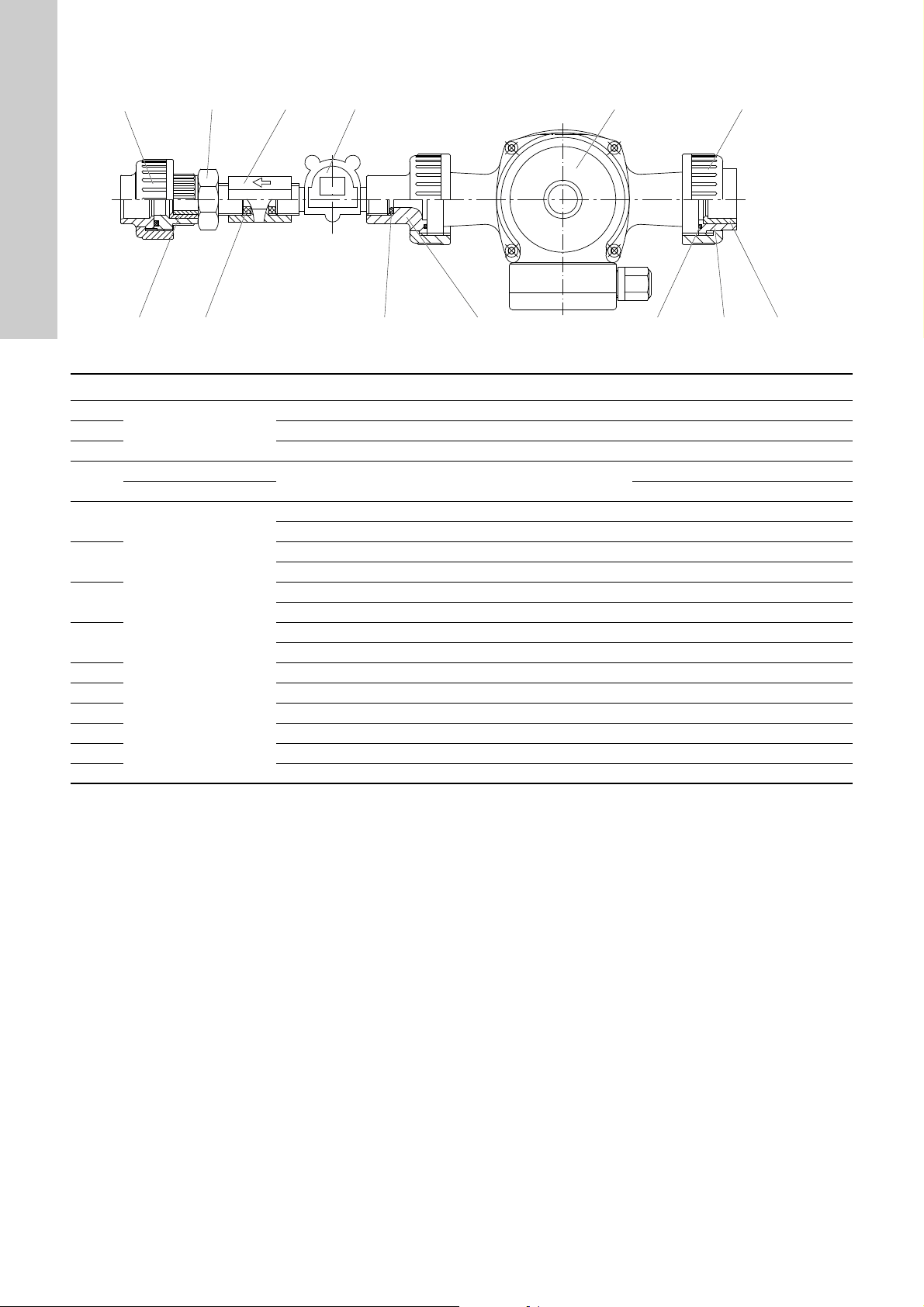
10.7 Bypass, circulating pump 230 V - 50 Hz, 120 V - 60 Hz
English (GB)
Fig. 34 OCD-164-700 to -2000
Pos. OCD-164 Description Product No.
30.1
30.5 Reduction, short 96688439 (53.183-25-20)
30.6 Connection nipple 96688427 (53.095-20-1/2)
30.10
30.12
30.13
30.14
30.15
30.16 Reduction, short 96688440 (53.183-32-25)
30.17 Flat gasket 96728862 (54.027)
30.18 Screw-in part, G 1/2" 95723548 (12.6492-410)
30.31 Impeller counter FHKU 100 91834753 (12.6010-1)
30.32 O-ring 96688273 (52416)
30.40 Post-mixer 95727697 (12.7136-300)
-30 to -2000
-30 to -350
-700 to -2000 95720032 (53.625-160)
-30 to -2000
Screw connection, DN 20 96688360 (53.055-25)
Flow limiter, 8 or 16 l/min
Circulation pump, 115 V/60 Hz 96688549 (53.650-105)
Circulation pump, 230 V/50 Hz 96688548 (53.650-001)
Union nut, DN 25 96688378 (53.058-32)
Vers. 115 V/union nut, DN 20 91835736 (53.058-25)
O-ring 91835567 (52.126)
Vers. 115 V/flat gasket 96728899 (54.142)
Insert, DN 25 96680700 (12.3503-400)
Vers. 115 V/insert, DN 20 96688366 (53.056-25)
TM04 8229 4510
95729418 (53.625-80)
44
Page 45

10.8 Bypass (version solenoid valve/ball valve, batch mode)
'1
Fig. 35 OCD-164-30 to OCD-164-220
English (GB)
TM04 8226 4510
Fig. 36 OCD-164-350
Fig. 37 OCD-164-700 to OCD-164-2000
TM04 8227 4510
TM04 8228 4510
45
Page 46

English (GB)
Pos. 164-OCD Description Product No.
30.40
30.50 -30 to -2000
30.51
30.52 -350 to -2000 Reduction, short 96688439 (53.183-25-20)
30.53 -350 to -2000 Reduction, short 96688438 (53.183-20-16)
30.54 -2000 Bush 96688411 (53.081-25)
30.57 -700 to -2000 Screw-in part, DN 20 96688372 (53.057-25)
30.58 -700 to -2000 O-ring 91835574 (52141)
30.60
30.61 -700 to -2000 Union nut, DN 20 91835736 (53.058-25)
30.62
30.63
30.64 Reduction, short 96688439 (53.183-25-20)
3065 Reduction, short 96688438 (53.183-20-16)
30.67 Adhesive pipe, PVC, DN 10 95729425 (12.1471)
30.80 Connection nipple 96681152 (12.6674-400)
30.81 O-ring 91835569 (52.131)
30.82 Screw connection, DN 10 96728050 (53.863-16)
-30 to -220 Pressure loading valve, DN 8 95729419 (12.6473-320)
-350 to -2000 Pressure loading valve, DN 20 96376567 (525-1113)
Solenoid valve, PVC, 230 V, 50 Hz 96688597 (53919-10)
Solenoid valve, PVC, 115 V, 60 Hz 91836553 (53.919-11)
-350 to -2000 Ball valve, DN 10 95729424 (53.564-16)
-30 Needle valve 95700504 (12.6675-400)
-120 to -220 Needle valve 95718301 (12.6675-420)
-700 to -2000 Impeller counter FHKU 100 91834753 (12.6010-1)
-220 Impeller counter FHKU 40 91836632 (12.6010-2)
-350 Impeller counter FHKU 56 95712071 (12.6010-3)
-120 Impeller counter FHKU 20 96681088 (12.6010-5)
-30 Impeller counter FHKU 15 91836552 (12.6010-6)
-30 to -350 Insert, G 1/4" 95729420 (12.6739-400)
-700 to -2000 Insert, DN 20- G 1/2" 96708974 (12.6202-400)
O-ring for FHKU 100 96688273 (52.416)
O-ring for FHKU 15-56 91835625 (52.337)
-30 to -2000
46
Page 47

10.9 Bypass for external booster pump
Fig. 38 Assembly drawing OCD-164-700 to OCD-164-2000
Pos. OCD-164 Description Product No.
30.2
30.3 O-ring 91835574 (52.141)
30.4 Screw-in part, DN 20 96688372 (53.057-25)
30.5 Reduction, short 96688439 (53183-25-20)
30.6 Connection nipple 96688427 (53.095-20-1/2)
30.10
30.11
30.30 Screw-in part, DN 20, G 1/2", IG 96708974 (12.6202-400)
30.31 Impeller counter FHKU 100 91834753 (12.6010-1)
30.32 O-ring 96688273 (52.416)
30.40 Post-mixer 95727697 (12.7136-300)
-30 to -2000
-30 to -350 Flow limiter, 8 l/min 95729418 (53.625-80)
-700 to -2000 Flow limiter, 16 l/min 95720032 (53.625-160)
-30 to -2000
Union nut, DN 20 91835736 (53.058-25)
Flat gasket 96728862 (54.027)
English (GB)
TM04 8230 4510
47
Page 48

11. Accessories
0.0 0.2 0.4 0.6 0.8 1.0 1.2 1.4 1.6 1.8 2.0 2.2
Q [m³/h]
0
20
40
60
80
100
120
140
160
180
200
220
H
[m]
0.0 0.1 0.2 0.3 0.4 0. 5 0.6
Q [l/s]
0
400
800
1200
1600
2000
p
[kP a]
CR, CRE 1
50 Hz
IS O 9906 Annex A
-2
-3 (E )
-4
-5
-6
-7 (E )
-8
-9
-10
-11 (E )
-12
-13
-15 (E )
-17
-19 (E )
-21
-23 (E )
-25
-27
-30 (E )
-33
-36 (E )
English (GB)
11.1 External booster pump
The booster pump is selected according to the difference between the pressure of dilution water supply and the system pressure at the
injection unit.
11.1.1 Technical data
Fig. 39 Technical data for the booster pump, material SS 1.4404
11.1.2 Pump types
Pump type
Increase of
pressure
Version Voltage
CR 1-3 Approx. 18 m
CR 1-5 Approx. 30 m 95701941 (660-0018-1)
CR 1-7 Approx. 40 m 95720986 (660-0019-1)
CR 1-9 Approx. 52 m
with connection
screwing, DN 25
CR 1-11 Approx. 62 m 95729341 (660-0021-1)
48
3 x 220-240 V /
380-415 V, 50 Hz
Nominal current
[A]
1.66 0.377
2.5 0.55
TM04 8231 4510
Motor [kW] Product No.
95713041 (660-0017-1)
95729340 (660-0020-1)
Page 49

11.1.3 Dimensions
%
%
º
º
[º
[
*
*
[º
'
'
0[
5S
*
*
)*-',1$16,-,6
31'1
$2YDO
º
º
English (GB)
Fig. 40 Dimensioning of booster pump
Pump type Motor [kW]
CR 1-2
CR 1-4 272 463 297 488
CR 1-5 290 481 315 506
CR 1-6 308 499 333 524
CR 1-7 326 517 351 542 25
CR 1-8
CR 1-10 380 571 405 596
CR 1-11 398 589 423 614 27
CR 1-12
CR 1-13 440 671 465 696 25
CR 1-15 476 707 501 732 26 30
CR 1-17
CR 1-19 548 779 573 804 34
CR 1-21 584 815 609 840 30 35
CR 1-23 620 851 645 876 31 36
CR 1-25
CR 1-27 733 1014 CR 1-30 787 1068 - 46
CR 1-33
CR 1-36 895 1216 - 49
0.37
0.55
0.75
1.1
1.5
2.2
Oval flange DIN flange
B1 B1 + B2 B1 B1 + B2
254 445 279 470
344 535 369 560
422 653 447 678 24
512 743 537 768
--
Dimensions Net weight
697 978
841 1162 - 47
CR
D1 D2
141 109
178 110
Oval
flange
18
19
20
21
22
29
-
DIN flange
TM04 8237 4510
23CR 1-3
24
26CR 1-9 362 553 387 578
29
33
44
49
Page 50

11.2 Load unit for booster pump
Note
Caution
///
3(
89:
$
$
.
0
3(
///
3(
89:
$
$
.
0
3(
Note
Caution
Note
'1
º
5
S
º
English (GB)
The booster pump is connected to the controller of the system via
a load unit.
Fig. 41 Load unit for booster pump
Pos. Description
Motor-protective circuit breaker
The nominal current of the pump is adjusted at the
1
motor-protective circuit breaker, see data sheet of
booster pump.
Connection cable
2
The load unit is connected to the controller of the system.
Terminal 22 = L, terminal 23 = N, terminal 24 = PE
If a system with bypass for the external booster
pump is selected, observe the following table for the
selection of the load unit.
When adjusting the motor-protective circuit breaker,
observe the nominal current of the dosing pump.
Pump type Electrical data Product No.
CR 1-3
CR 1-5
CR 1-7
CR 1-9,
CR 1-11
1.6 - 2.5 A, 230 V, 50/60 Hz 96728835 (535-50)
1.6 - 2.5 A, 115 V, 50/60 Hz 96728836 (535-51)
2.5 - 4.0 A, 230 V, 50/60 Hz 96728837 (535-52)
2.5 - 4.0 A, 115 V, 50/60 Hz 96728838 (535-53)
11.3 Hose connections/hose
Hose connection, DN 20 Product No.
Hose connection DN 20 - ID 25 mm
with 2 hose clamps.
96727534 (529-050)
Fig. 43 Hose connection
Connection screwing Product No.
Connection screwing for external
booster pump Rp 1" AG - ID 25 mm
96727536 (529-051)
with 2 hose clamps.
TM04 8232 4510
Fig. 44 Connection screwing for external booster pump
PVC hose Length Product No.
5 m 95700198 (526-030/5)
PVC hose, ID 25 mm,
PN 6
10 m 95700852 (526-030/10)
25 m 95729449 (526-030/25)
Max. system pressure for PVC hose 6 bar.
For a higher system pressure, install a PVC pipe
(DN 16).
11.4 Gas sensor and gas warning device
The gas sensor can be mounted at the rear of the system
underneath the reactor. The required fastening screw
(countersunk screw M6x20) is included in the mounting material
of the system.
Description Product No.
Gas sensor 91835237 (314-011)
Conex DIS-G gas warning unit 96644515 (307-2000)
Observe the installation and operating instructions of
the Conex DIS-G gas warning unit or the 314 gas
sensor.
TM04 8234 4510
TM04 8235 4510
Fig. 42 Terminal connection diagram load unit (booster pump)
50
The gas sensor cannot be connected directly to the
controller of the system. A gas warning unit is
required in addition. Cabling is carried out on site.
TM04 8233 4510
Page 51

12. Current setting data
Settings of the system
System type OCD-164-030 OCD-164-120 OCD-164-220 OCD-164-350
OCD-164-700 OCD-164-1000 OCD-164-1500 OCD-164-2000
Main water quantity m3/h
Default ClO
Operation mode
Batch mode Batch concentration: g/l
Current input 0-20 mA 4-20 mA others
Contact input Contact water meter: Pulses/litre
Manual control
Bus control
Flow rates
Bypass water quantity l/h Limit - % + %
Flow NaClO
Flow HCl l/h Stroke setting of pump %
2
2
l/h Stroke setting of pump %
ppm
English (GB)
System mode
Automatic operation
Manual operation Dosing flow %
Startup
Date
Company
Signature
Remarks
51
Page 52

13. Quick Guide
F1 F2 F3 F4
Main menu
1 Automatic
2 Manual operation
3 Logbook
12 3
4
5
6
F1 F2 F3 F4
Auto: 20 mA
Dosing
Bypass
ClO
2
active
100 %
435 l/h
10 g/h
F1 F2 F3 F4
Dosing
Bypass
ClO
2
3 Logbook
100 %
435 l/h
10 g/h
English (GB)
Fig. 45 Controller, overview
Pos. Description
1
2
3
4
5
6
Display
• 1 = Switch to submenu using [F1].
• 2 = Switch to submenu using [F2].
• 3 = Switch to submenu using [F3].
Function keys [F1], [F2, [F3]
• Switch to respective submenu.
Arrow keys
• Scroll in respective menu.
[F4] key
• Acknowledge alarm messages.
[Enter] key
• Switch system on/off.
• Confirm inputs.
[Escape] key
• Return to preceding menu.
• Return to main menu (press key several times).
• Cancel input.
Example: automatic mode, current input signal
TM04 8236 4510
Fig. 46 Display in operating state
In the operating state, the most important information is
displayed, such as dosing, bypass water quantity, and system
capacity.
The user cannot switch to the submenus using the [F1], [F2], [F3]
and [F4] keys.
Logbook
• Press the [UP] or [DOWN] arrow key.
TM04 8236 4510
TM04 8236 4510
Fig. 47 Display in operating state
• Subsequently press the [F3] key. The "Logbook" menu with
the items "active alarms", "alarm list", and "operating hours" is
now loaded.
• Use the [Escape] key to return to the automatic operation
display menu.
14. Disposal
This product or parts of it must be disposed of in an
environmentally sound way:
1. Use the public or private waste collection service.
2. If this is not possible, contact the nearest Grundfos company
or service workshop.
52
Page 53

Declaration of conformity 1
GB: EU declaration of conformity
We, Grundfos, declare under our sole responsibility that the products
Oxiperm OCD-164, to which the declaration below relates, are in
conformity with the Council Directives listed below on the approximation
of the laws of the EU member states.
DE: EU-Konformitätserklärung
Wir, Grundfos, erklären in alleiniger Verantwortung, dass die Produkte
Oxiperm OCD-164, auf die sich diese Erklärung beziehen, mit den
folgenden Richtlinien des Rates zur Angleichung der Rechtsvorschriften
der EU-Mitgliedsstaaten übereinstimmen.
FI: EU-vaatimustenmukaisuusvakuutus
Grundfos vakuuttaa omalla vastuullaan, että tuotteet Oxiperm OCD-164,
joita tämä vakuutus koskee, ovat EU:n jäsenvaltioiden lainsäädännön
lähentämiseen tähtäävien Euroopan neuvoston direktiivien vaatimusten
mukaisia seuraavasti.
IT: Dichiarazione di conformità UE
Grundfos dichiara sotto la sua esclusiva responsabilità che i prodotti
Oxiperm OCD-164, ai quale si riferisce questa dichiarazione, sono
conformi alle seguenti direttive del Consiglio riguardanti il
riavvicinamento delle legislazioni degli Stati membri UE.
PT: Declaração de conformidade UE
A Grundfos declara sob sua única responsabilidade que os produtos
Oxiperm OCD-164, aos quais diz respeito a declaração abaixo, estão em
conformidade com as Directivas do Conselho sobre a aproximação das
legislações dos Estados Membros da UE.
SI: Izjava o skladnosti EU
V Grundfosu s polno odgovornostjo izjavljamo, da je izdelek Oxiperm
OCD-164, na katerega se spodnja izjava nanaša, v skladu s spodnjimi
direktivami Sveta o približevanju zakonodaje za izenačevanje pravnih
predpisov držav članic EU.
CZ: Prohlášení o shodě EU
My firma Grundfos prohlašujeme na svou plnou odpovědnost, že výrobek
Oxiperm OCD-164, na který se toto prohlášení vztahuje, je v souladu s
níže uvedenými ustanoveními směrnice Rady pro sblížení právních
předpisů členských států Evropského společenství.
ES: Declaración de conformidad de la UE
Grundfos declara, bajo su exclusiva responsabilidad, que los productos
Oxiperm OCD-164 a los que hace referencia la siguiente declaración
cumplen lo establecido por las siguientes Directivas del Consejo sobre la
aproximación de las legislaciones de los Estados miembros de la UE.
FR: Déclaration de conformité UE
Nous, Grundfos, déclarons sous notre seule responsabilité, que les
produits Oxiperm OCD-164, auxquels se réfère cette déclaration, sont
conformes aux Directives du Conseil concernant le rapprochement des
législations des États membres UE relatives aux normes énoncées
ci-dessous.
NL: EU-conformiteitsverklaring
Wij, Grundfos, verklaren geheel onder eigen verantwoordelijkheid dat de
producten Oxiperm OCD-164, waarop de onderstaande verklaring
betrekking heeft, in overeenstemming zijn met de onderstaande
Richtlijnen van de Raad inzake de onderlinge aanpassing van de
wetgeving van de EU-lidstaten.
RU: Декларация о соответствии нормам ЕС
Мы, компания Grundfos, со всей ответственностью заявляем, что
изделия Oxiperm OCD-164, к которым относится нижеприведённая
декларация, соответствуют нижеприведённым Директивам Совета
Евросоюза о тождественности законов стран-членов ЕС.
— Machinery Directive (2006/42/EC).
Standards used: EN 809:2012,
DIN EN ISO 12100:2010
EN ISO 13849-1:2008.
— Low Voltage Directive (2014/35/EU).
Standard used: EN 61010-1:2011-07.
— EMC Directive (2014/30/EU).
Standards used:
EN 61000-3-11:2001
EN 61000-6-2:2006
EN 61000-6-4:2007+A1:2011
EN 61326-1:2013.
This EU declaration of conformity is only valid when published as part of
the Grundfos installation and operating instructions
(publication number 96709679).
Pfinztal, 1 May 2016
Declaration of conformity
Ulrich Stemick
Technical Director
Grundfos Water Treatment GmbH
Reetzstr. 85, D-76327 Pfinztal, Germany
Person authorised to compile technical file and
empowered to sign the EU declaration of conformity.
53
Page 54

Declaration of conformity RU
Declaration of conformity RU 2
Установки автоматические для приготовления и дозирования
диоксида хлора типа Oxiperm модели OCD 164, Pro OCD 162
сертифицированы на соответствие требованиям Технических
регламентов Таможенного союза: ТР ТС 004/2011 «О безопасности
низковольтного оборудования»; ТР ТС 010/2011 «О безопасности
машин и оборудования»; ТР ТС 020/2011 «Электромагнитная
совместимость технических средств».
Сертификат соответствия:
№ TC RU C-DK.АИ30.B.01026, срок действия до 19.10.2019г.
Выдан: Органом по сертификации продукции
«ИВАНОВО-
СЕРТИФИКАТ» ООО «Ивановский Фонд Сертификации».
Адрес: 153032, Российская Федерация, г. Иваново, ул.
Станкостроителей, д.1.
Истра, 1 марта 2016 г.
Касаткина В. В.
Руководитель отдела качества,
экологии и охраны труда
ООО Грундфос Истра, Россия
143581, Московская область,
Истринский район,
дер. Лешково, д.188
54
Page 55

Argentina
Bombas GRUNDFOS de Argentina S.A.
Ruta Panamericana km. 37.500 Centro
Industrial Garin
1619 - Garin Pcia. de B.A.
Phone: +54-3327 414 444
Telefax: +54-3327 411 111
Australia
GRUNDFOS Pumps Pty. Ltd.
P.O. Box 2040
Regency Park
South Australia 5942
Phone: +61-8-8461-4611
Telefax: +61-8-8340 0155
Austria
GRUNDFOS Pumpen Vertrieb Ges.m.b.H.
Grundfosstraße 2
A-5082 Grödig/Salzburg
Tel.: +43-6246-883-0
Telefax: +43-6246-883-30
Belgium
N.V. GRUNDFOS Bellux S.A.
Boomsesteenweg 81-83
B-2630 Aartselaar
Tél.: +32-3-870 7300
Télécopie: +32-3-870 7301
Belarus
Представительство ГРУНДФОС в
Минске
220125, Минск
ул. Шафарнянская, 11, оф. 56
Тел.: +7 (375 17) 286 39 72, 286 39 73
Факс: +7 (375 17) 286 39 71
E-mail: minsk@grundfos.com
Bosnia/Herzegovina
GRUNDFOS Sarajevo
Trg Heroja 16,
BiH-71000 Sarajevo
Phone: +387 33 713 290
Telefax: +387 33 659 079
e-mail: grundfos@bih.net.ba
Brazil
BOMBAS GRUNDFOS DO BRASIL
Av. Humberto de Alencar Castelo Branco,
630
CEP 09850 - 300
São Bernardo do Campo - SP
Phone: +55-11 4393 5533
Telefax: +55-11 4343 5015
Bulgaria
Grundfos Bulgaria EOOD
Slatina District
Iztochna Tangenta street no. 100
BG - 1592 Sofia
Tel. +359 2 49 22 200
Fax. +359 2 49 22 201
email: bulgaria@grundfos.bg
Canada
GRUNDFOS Canada Inc.
2941 Brighton Road
Oakville, Ontario
L6H 6C9
Phone: +1-905 829 9533
Telefax: +1-905 829 9512
China
Grundfos Alldos
Dosing & Disinfection
ALLDOS (Shanghai) Water Technology
Co. Ltd.
West Unit, 1 Floor, No. 2 Building (T 4-2)
278 Jinhu Road, Jin Qiao Export
Processing Zone
Pudong New Area
Shanghai, 201206
Phone: +86 21 5055 1012
Telefax: +86 21 5032 0596
E-mail: grundfosalldos-C N@grundfos.com
China
GRUNDFOS Pumps (Shanghai) Co. Ltd.
10F The Hub, No. 33 Suhong Road
Minhang District
Shanghai 201106
PRC
Phone: +86-21 6122 5222
Telefax: +86-21 6122 5333
COLOMBIA
GRUNDFOS Colombia S.A.S.
Km 1.5 vía Siberia-Cota Conj. Potrero
Chico,
Parque Empresarial Arcos de Cota Bod.
1A.
Cota, Cundinamarca
Phone: +57(1)-2913444
Telefax: +57(1)-8764586
Croatia
GRUNDFOS CROATIA d.o.o.
Cebini 37, Buzin
HR-10010 Zagreb
Phone: +385 1 6595 400
Telefax: +385 1 6595 499
www.hr.grundfos.com
GRUNDFOS Sales Czechia and
Slovakia s.r.o.
Čapkovského 21
779 00 Olomouc
Phone: +420-585-716 111
Denmark
GRUNDFOS DK A/S
Martin Bachs Vej 3
DK-8850 Bjerringbro
Tlf.: +45-87 50 50 50
Telefax: +45-87 50 51 51
E-mail: info_GDK@grundfos.com
www.grundfos.com/DK
Estonia
GRUNDFOS Pumps Eesti OÜ
Peterburi tee 92G
11415 Tallinn
Tel: + 372 606 1690
Fax: + 372 606 1691
Finland
OY GRUNDFOS Pumput AB
Trukkikuja 1
FI-01360 Vantaa
Phone: +358-(0)207 889 500
France
Pompes GRUNDFOS Distribution S.A.
Parc d’Activités de Chesnes
57, rue de Malacombe
F-38290 St. Quentin Fallavier (Lyon)
Tél.: +33-4 74 82 15 15
Télécopie: +33-4 74 94 10 51
Germany
GRUNDFOS Water Treatment GmbH
Reetzstraße 85
D-76327 Pfinztal (Söllingen)
Tel.: +49 7240 61-0
Telefax: +49 7240 61-177
E-mail: gwt@grundfos.com
Germany
GRUNDFOS GMBH
Schlüterstr. 33
40699 Erkrath
Tel.: +49-(0) 211 929 69-0
Telefax: +49-(0) 211 929 69-3799
E-mail: infoservice@grundfos.de
Service in Deutschland:
E-mail: kundendienst@grundfos.de
Greece
GRUNDFOS Hellas A.E.B.E.
20th km. Athinon-Markopoulou Av.
P.O . B o x 71
GR-19002 Peania
Phone: +0030-210-66 83 400
Telefax: +0030-210-66 46 273
Hong Kong
GRUNDFOS Pumps (Hong Kong) Ltd.
Unit 1, Ground floor
Siu Wai Industrial Centre
29-33 Wing Hong Street &
68 King Lam Street, Cheung Sha Wan
Kowloon
Phone: +852-27861706 / 27861741
Telefax: +852-27858664
Hungary
GRUNDFOS Hungária Kft.
Park u. 8
H-2045 Törökbálint,
Phone: +36-23 511 110
Telefax: +36-23 511 111
India
GRUNDFOS Pumps India Private Limited
118 Old Mahabalipuram Road
Thoraipakkam
Chennai 600 097
Phone: +91-44 4596 6800
Indonesia
PT. GRUNDFOS POMPA
Graha Intirub Lt. 2 & 3
Jln. Cililitan Besar No.454. Makasar,
Jakarta Timur
ID-Jakarta 13650
Phone: +62 21-469-51900
Telefax: +62 21-460 6910 / 460 6901
Ireland
GRUNDFOS (Ireland) Ltd.
Unit A, Merrywell Business Park
Ballymount Road Lower
Dublin 12
Phone: +353-1-4089 800
Telefax: +353-1-4089 830
Italy
GRUNDFOS Pompe Italia S.r.l.
Via Gran Sasso 4
I-20060 Truccazzano (Milano)
Tel.: +39-02-95838112
Telefax: +39-02-95309290 / 95838461
Japan
GRUNDFOS Pumps K.K.
1-2-3, Shin-Miyakoda, Kita-ku
Hamamatsu
431-2103 Japan
Phone: +81 53 428 4760
Telefax: +81 53 428 5005
Korea
GRUNDFOS Pumps Korea Ltd.
6th Floor, Aju Building 679-5
Yeoksam-dong, Kangnam-ku, 135-916
Seoul, Korea
Phone: +82-2-5317 600
Telefax: +82-2-5633 725
Latvia
SIA GRUNDFOS Pumps Latvia
Deglava biznesa centrs
Augusta Deglava ielā 60, LV-1035, Rīga,
Tālr.: + 371 714 9640, 7 149 641
Fakss: + 371 914 9646
Lithuania
GRUNDFOS Pumps UAB
Smolensko g. 6
LT-03201 Vilnius
Tel: + 370 52 395 430
Fax: + 370 52 395 431
Malaysia
GRUNDFOS Pumps Sdn. Bhd.
7 Jalan Peguam U1/25
Glenmarie Industrial Park
40150 Shah Alam
Selangor
Phone: +60-3-5569 2922
Telefax: +60-3-5569 2866
Mexico
Bombas GRUNDFOS de México S.A. de
C.V.
Boulevard TLC No. 15
Parque Industrial Stiva Aeropuerto
Apodaca, N.L. 66600
Phone: +52-81-8144 4000
Telefax: +52-81-8144 4010
Netherlands
GRUNDFOS Netherlands
Velu we zo om 35
1326 AE Almere
Postbus 22015
1302 CA ALMERE
Tel.: +31-88-478 6336
Telefax: +31-88-478 6332
E-mail: info_gnl@grundfos.com
New Zealand
GRUNDFOS Pumps NZ Ltd.
17 Beatrice Tinsley Crescent
North Harbour Industrial Estate
Albany, Auckland
Phone: +64-9-415 3240
Telefax: +64-9-415 3250
Norway
GRUNDFOS Pumper A/S
Strømsveien 344
Postboks 235, Leirdal
N-1011 Oslo
Tlf.: +47-22 90 47 00
Telefax: +47-22 32 21 50
Poland
GRUNDFOS Pompy Sp. z o.o.
ul. Klonowa 23
Baranowo k. Poznania
PL-62-081 Przeźmierowo
Tel: (+48-61) 650 13 00
Fax: (+48-61) 650 13 50
Portugal
Bombas GRUNDFOS Portugal, S.A.
Rua Calvet de Magalhães, 241
Apartado 1079
P-2770-153 Paço de Arcos
Tel.: +351-21-440 76 00
Telefax: +351-21-440 76 90
Romania
GRUNDFOS Pompe România SRL
Bd. Biruintei, nr 103
Pantelimon county Ilfov
Phone: +40 21 200 4100
Telefax: +40 21 200 4101
E-mail: romania@grundfos.ro
Russia
ООО Грундф ос
ул. Школьная, 39-41
Москва, RU-109544, Russia
Тел. (+7) 495 737 30 00, 564 8800
Факс (+7) 495 737 75 36, 564 8811
E-mail grundfos.moscow@grundfos.com
Serbia
GRUNDFOS Predstavništvo Beograd
Dr. Milutina Ivkovića 2a/29
YU-11000 Beograd
Phone: +381 11 26 47 877 / 11 26 47 496
Telefax: +381 11 26 48 340
Singapore
GRUNDFOS (Singapore) Pte. Ltd.
25 Jalan Tukang
Singapore 619264
Phone: +65-6681 9688
Telefax: +65-6681 9689
Slovakia
GRUNDFOS s.r.o.
Prievozská 4D
821 09 BRATISLAVA
Phona: +421 2 5020 1426
sk.grundfos.com
Slovenia
GRUNDFOS LJUBLJANA, d.o.o.
Leskoškova 9e, 1122 Ljubljana
Phone: +386 (0) 1 568 06 10
Telefax: +386 (0)1 568 0619
E-mail: tehnika-si@grundfos.com
South Africa
Grundfos (PTY) Ltd.
Corner Mountjoy and George Allen Roads
Wilbart Ext. 2
Bedfordview 2008
Phone: (+27) 11 579 4800
Fax: (+27) 11 455 6066
E-mail: lsmart@grundfos.com
Spain
Bombas GRUNDFOS España S.A.
Camino de la Fuentecilla, s/n
E-28110 Algete (Madrid)
Tel.: +34-91-848 8800
Telefax: +34-91-628 0465
Sweden
GRUNDFOS AB
(Box 333) Lunnagårdsgatan 6
431 24 Mölndal
Tel.: +46 31 332 23 000
Telefax: +46 31-331 94 60
Switzerland
GRUNDFOS ALLDOS International AG
Schönmattstraße 4
CH-4153 Reinach
Tel.: +41-61-717 5555
Telefax: +41-61-717 5500
E-mail: grundfosalldos-CH@grundfos.com
Switzerland
GRUNDFOS Pumpen AG
Bruggacherstrasse 10
CH-8117 Fällanden/ZH
Tel.: +41-44-806 8111
Telefax: +41-44-806 8115
Taiwan
GRUNDFOS Pumps (Taiwan) Ltd.
7 Floor, 219 Min-Chuan Road
Taichung, Taiwan, R.O.C.
Phone: +886-4-2305 0868
Telefax: +886-4-2305 0878
Thailand
GRUNDFOS (Thailand) Ltd.
92 Chaloem Phrakiat Rama 9 Road,
Dokmai, Pravej, Bangkok 10250
Phone: +66-2-725 8999
Telefax: +66-2-725 8998
Turkey
GRUNDFOS POMPA San. ve Tic. Ltd. Sti.
Gebze Organize Sanayi Bölgesi
Ihsan dede Caddesi,
2. yol 200. Sokak No. 204
41490 Gebze/ Kocaeli
Phone: +90 - 262-679 7979
Telefax: +90 - 262-679 7905
E-mail: satis@grundfos.com
Ukraine
Бізнес Центр Європа
Столичне шосе, 103
м. Київ, 03131, Україна
Телефон : (+38 044) 237 04 00
Факс.: (+38 044) 237 04 01
E-mail: ukraine@grundfos.com
United Arab Emirates
GRUNDFOS Gulf Distribution
P.O. Box 16768
Jebel Ali Free Zone
Dubai
Phone: +971-4- 8815 166
Telefax: +971-4-8815 136
United Kingdom
GRUNDFOS Pumps Ltd.
Grovebury Road
Leighton Buzzard/Beds. LU7 4TL
Phone: +44-1525-850000
Telefax: +44-1525-850011
U.S.A.
GRUNDFOS Pumps Corporation
17100 West 118th Terrace
Olathe, Kansas 66061
Phone: +1-913-227-3400
Telefax: +1-913-227-3500
Uzbekistan
Grundfos Tashkent, Uzbekistan The
Representative Office of Grundfos
Kazakhstan in Uzbekistan
38a, Oybek street, Tashkent
Телефон: (+998) 71 150 3290 / 71 150
3291
Факс: (+998) 71 150 3292
Addresses revised 09.08.2017
Grundfos companies
Page 56

96709679 1117
ECM: 1215430
www.grundfos.com
The name Grundfos, the Grundfos logo, and be think innovate are registered trademarks owned by Grundfos Holding A/S or Grundfos A/S, Denmark. All rights reserved worldwide. © Copyright Grundfos Holding A/S
 Loading...