

Page 1

GRUNDFOS INSTRUCTIONS
TPE, TPED, NKE, NKGE,
NBE, NBGE
Installation and operating instructions
Page 2

Declaration of conformity
Declaration of conformity
GB: EC declaration of conformity
We, Grundfos, declare under our sole responsibility that the products
TPE, TPED, NKE, NKGE, NBE and NBGE, to which this declaration
relates, are in conformity with these Council directives on the
approximation of the laws of the EC member states:
— Machinery Directive (2006/42/EC).
Standards used: EN 809:1998 and EN 60204-1:2006.
— Low Voltage Directive (2006/95/EC).
Standard used: EN 61800-5-1.
— EMC Directive (2004/108/EC).
Standard used: EN 61800-3:2004.
— Ecodesign Directive (2009/125/EC).
Water pumps:
Commission Regulation No 547/2012.
Applies only to water pumps marked with the minimum efficiency
index MEI. See pump nameplate.
This EC declaration of conformity is only valid when published as part of
the Grundfos installation and operating instructions (publication number
96782376 1112).
CZ: ES prohlášení o shodě
My firma Grundfos prohlašujeme na svou plnou odpovědnost, že výrobky
TPE, TPED, NKE, NKGE, NBE a NBGE, na něž se toto prohlášení
vztahuje, jsou v souladu s ustanoveními směrnice Rady pro sblížení
právních předpisů členských států Evropského společenství v oblastech:
—Směrnice pro strojní zařízení (2006/42/ES).
Použité normy: EN 809:1998 a EN 60204-1:2006.
—Směrnice pro nízkonapět’ové aplikace (2006/95/ES).
Použitá norma: EN 61800-5-1.
—Směrnice pro elektromagnetickou kompatibilitu (EMC)
(2004/108/ES).
Použitá norma: EN 61800-3:2004.
—Směrnice o ekodesignu (2009/125/ES).
Vodní čerpadla:
Nařízení Komise č. 547/2012.
Vztahuje se pouze na vodní čerpadla označená minimální účinností
index MEI. Viz typový štítek čerpadla.
Toto ES prohlášení o shodě je platné pouze tehdy, pokud je zveřejněno
jako součást instalačních a provozních návodů Grundfos (publikace číslo
96782376 1112).
DE: EG-Konformitätserklärung
Wir, Grundfos, erklären in alleiniger Verantwortung, dass die Produkte
TPE, TPED, NKE, NKGE, NBE und NBGE, auf die sich diese Erklärung
bezieht, mit den folgenden Richtlinien des Rates zur Angleichung der
Rechtsvorschriften der EU-Mitgliedsstaaten übereinstimmen:
— Maschinenrichtlinie (2006/42/EG).
Normen, die verwendet wurden: EN 809:1998 und
EN 60204-1:2006.
— Niederspannungsrichtlinie (2006/95/EG).
Norm, die verwendet wurde: EN 61800-5-1.
— EMV-Richtlinie (2004/108/EG).
Norm, die verwendet wurde: EN 61800-3:2004.
— ErP-Richtlinie (2009/125/EG).
Wasserpumpen:
Verordnung der Europäischen Kommission Nr. 547/2012.
Gilt nur für Pumpen, für die der Mindesteffizienzindex (MEI)
anzugeben ist. Siehe Typenschild der Pumpe.
Diese EG-Konformitätserklärung gilt nur, wenn sie in Verbindung mit der
Grundfos Montage- und Betriebsanleitung (Veröffentlichungsnummer
96782376 1112) veröffentlicht wird.
GR: ∆ήλωση συμμόρφωσης EC
Εμείς, η Grundfos, δηλώνουμε με αποκλειστικά δική μας ευθύνη ότι
τα προϊόντα TPE, TPED, NKE, NKGE, NBE και NBGE στα οποία
αναφέρεται η παρούσα δήλωση, συμμορφώνονται με τις εξής Οδηγίες
του Συμβουλίου περί προσέγγισης των νομοθεσιών των κρατών μελών
της ΕΕ:
— Οδηγία για μηχανήματα (2006/42/EC).
Πρότυπα που χρησιμοποιήθηκαν: EN 809:1998 και
EN 60204-1:2006.
— Οδηγία χαμηλής τάσης (2006/95/EC).
Πρότυπο που χρησιμοποιήθηκε: EN 61800-5-1.
— Οδηγία Ηλεκτρομαγνητικής Συμβατότητας
Πρότυπο που χρησιμοποιήθηκε: EN 61800-3:2004.
— Οδηγία Οικολογικού Σχεδιασμού (2009/125/EC).
Αντλίες νερού:
Ρύθμιση πρώτης εκκίνησης Νο 547/2012.
Ισχύει μόνο για αντλίες νερού που φέρουν τον ελάχιστο δείκτη
απόδοσης ΜΕΙ. Βλέπε πινακίδα αντλίας.
Αυτή η δήλωση συμμόρφωσης EC ισχύει μόνον όταν συνοδεύει τις
οδηγίες εγκατάστασης και λειτουργίας της Grundfos (κωδικός εντύπου
96782376 1112).
(EMC) (2004/108/EC).
BG: EC декларация за съответствие
Ние, фирма Grundfos, заявяваме с пълна отговорност, че продуктите
TPE, TPED, NKE, NKGE, NBE и NBGE, за които се отнася
настоящата декларация, отговарят на следните указания на Съвета
за уеднаквяване на правните разпоредби на държавите членки на
ЕС:
— Директива за машините (2006/42/EC).
Приложени стандарти: EN 809:1998 и EN 60204-1:2006.
— Директива за нисковолтови системи (2006/95/EC).
Приложен стандарт: EN 61800-5-1.
— Директива за електромагнитна съвместимост (2004/108/EC).
Приложен стандарт
— Директива за екодизайн (2009/125/EC).
Водни помпи:
Наредба No 547/2012 на Европейската комисия.
Отнася се само за водни помпи, маркирани с минималният
индекс за ефективност MEI. Вижте табелата с данни на помпата.
Тази ЕС декларация за съответствие е валидна само когато е
публикувана като част от инструкциите за монтаж и експлоатация на
Grundfos (номер на
: EN 61800-3:2004.
публикацията 96782376 1112).
DK: EF-overensstemmelseserklæring
Vi, Grundfos, erklærer under ansvar at produkterne TPE, TPED, NKE,
NKGE, NBE og NBGE som denne erklæring omhandler, er i
overensstemmelse med disse af Rådets direktiver om indbyrdes
tilnærmelse til EF-medlemsstaternes lovgivning:
— Maskindirektivet (2006/42/EF).
Anvendte standarder: EN 809:1998 og EN 60204-1:2006.
— Lavspændingsdirektivet (2006/95/EF).
Anvendt standard: EN 61800-5-1.
— EMC-direktivet (2004/108/EF).
Anvendt standard: EN 61800-3:2004.
— Ecodesigndirektivet (2009/125/EF).
Vandpumper:
Kommissionens forordning nr. 547/2012.
Gælder kun vandpumper der er mærket med
mindsteeffektivitetsindekset MEI. Se pumpens typeskilt.
Denne EF-overensstemmelseserklæring er kun gyldig når den publiceres
som en del af Grundfos-monterings- og driftsinstruktionen (publikationsnummer 96782376 1112).
EE: EL vastavusdeklaratsioon
Meie, Grundfos, deklareerime enda ainuvastutusel, et tooted TPE,
TPED, NKE, NKGE, NBE ja NBGE, mille kohta käesolev juhend käib,
on vastavuses EÜ Nõukogu direktiividega EMÜ liikmesriikide seaduste
ühitamise kohta, mis käsitlevad:
— Masinate ohutus (2006/42/EC).
Kasutatud standardid: EN 809:1998 ja EN 60204-1:2006.
— Madalpinge direktiiv (2006/95/EC).
Kasutatud standard: EN 61800-5-1.
— Elektromagnetiline ühilduvus (EMC direktiiv) (2004/108/EC).
Kasutatud standard: EN 61800-3:2004.
— Ökodisaini direktiiv (2009/125/EC).
Veepumbad:
Komisjoni regulatsioon nr 547/2012.
Kehtiv ainult veepumpadele, mis on märgitud miinimum kasuteguri
indeksiga MEI. Vaata pumba silti.
Käesolev EL-i vastavusdeklaratsioon kehtib ainult siis, kui see
avaldatakse Grundfosi paigaldus- ja kasutusjuhendi (avaldamisnumber
96782376 1112) osana.
ES: Declaración CE de conformidad
Nosotros, Grundfos, declaramos bajo nuestra entera responsabilidad
que los productos TPE, TPED, NKE, NKGE, NBE y NBGE, a los cuales
se refiere esta declaración, están conformes con las Directivas del
Consejo en la aproximación de las leyes de las Estados Miembros del
EM:
— Directiva de Maquinaria (2006/42/CE).
Normas aplicadas: EN 809:1998 y EN 60204-1:2006.
— Directiva de Baja Tensión (2006/95/CE).
Norma aplicada: EN 61800-5-1.
— Directiva EMC (2004/108/CE).
Norma aplicada: EN 61800-3:2004.
— Directiva sobre diseño ecológico (2009/125/CE).
Bombas de agua:
Reglamento de la Comisión Nº 547/2012.
Aplicable únicamente a las bombas de agua marcadas con el índice
de eficiencia mínima (IEM). Véase la placa de características de la
bomba.
Esta declaración CE de conformidad sólo es válida cuando se publique
como parte de las instrucciones de instalación y funcionamiento de
Grundfos (número de publicación 96782376 1112).
2
Page 3

FR: Déclaration de conformité CE
Nous, Grundfos, déclarons sous notre seule responsabilité, que les
produits TPE, TPED, NKE, NKGE, NBE et NBGE, auxquels se réfère
cette déclaration, sont conformes aux Directives du Conseil concernant
le rapprochement des législations des Etats membres CE relatives aux
normes énoncées ci-dessous:
— Directive Machines (2006/42/CE).
Normes utilisées: EN 809:1998 et EN 60204-1:2006.
— Directive Basse Tension (2006/95/CE).
Norme utilisée: EN 61800-5-1.
— Directive Compatibilité Electromagnétique CEM (2004/108/CE).
Norme utilisée : EN 61800-3:2004.
— Directive sur l'éco-conception (2009/125/CE).
Pompes à eau:
Règlement de la Commission Nº 547/2012.
S'applique uniquement aux pompes à eau marquées de l'indice de
performance minimum IEM. Voir plaque signalétique de la pompe.
Cette déclaration de conformité CE est uniquement valide lors de sa
publication dans la notice d'installation et de fonctionnement Grundfos
(numéro de publication 96782376 1112).
IT: Dichiarazione di conformità CE
Grundfos dichiara sotto la sua esclusiva responsabilità che i prodotti
TPE, TPED, NKE, NKGE, NBE e NBGE, ai quali si riferisce questa
dichiarazione, sono conformi alle seguenti direttive del Consiglio
riguardanti il riavvicinamento delle legislazioni degli Stati membri CE:
— Direttiva Macchine (2006/42/CE).
Norme applicate: EN 809:1998 e EN 60204-1:2006.
— Direttiva Bassa Tensione (2006/95/CE).
Norma applicata: EN 61800-5-1.
— Direttiva EMC (2004/108/CE).
Norma applicata: EN 61800-3:2004.
— Direttiva Ecodesign (2009/125/CE).
Pompe per acqua:
Regolamento CE n. 547/2012.
Applicabile solo a pompe per acqua con l'indice di efficienza minimo
MEI. Vedere la targhetta di identificazione della pompa.
Questa dichiarazione di conformità CE è valida solo quando pubblicata
come parte delle istruzioni di installazione e funzionamento Grundfos
(pubblicazione numero 96782376 1112).
LT: EB atitikties deklaracija
Mes, Grundfos, su visa atsakomybe pareiškiame, kad gaminiai TPE,
TPED, NKE, NKGE, NBE ir NBGE, kuriems skirta ši deklaracija, atitinka
šias Tarybos Direktyvas dėl Europos Ekonominės Bendrijos šalių narių
įstatymų suderinimo:
—Mašinų direktyva (2006/42/EB).
Taikomi standartai: EN 809:1998 ir EN 60204-1:2006.
—Žemų įtampų direktyva (2006/95/EB).
Taikomas standartas: EN 61800-5-1.
— EMS direktyva (2004/108/EB).
Taikomas standartas: EN 61800-3:2004.
— Ekologinio projektavimo direktyva (2009/125/EB).
Vandens siurbliai:
Komisijos reglamentas Nr. 547/2012.
Galioja tik vandens siurbliams, ant kurių nurodytas minimalus
efektyvumo koeficientas MEI. Žr. siurblio vardinę plokštelę.
Ši EB atitikties deklaracija galioja tik tuo atveju, kai yra pateikta kaip
"Grundfos" įrengimo ir naudojimo instrukcijos (leidinio numeris 96782376
1112) dalis.
NL: EC overeenkomstigheidsverklaring
Wij, Grundfos, verklaren geheel onder eigen verantwoordelijkheid dat
de producten TPE, TPED, NKE, NKGE, NBE en NBGE waarop deze
verklaring betrekking heeft, in overeenstemming zijn met de Richtlijnen
van de Raad in zake de onderlinge aanpassing van de wetgeving van de
EG Lidstaten betreffende:
— Machine Richtlijn (2006/42/EC).
Gebruikte normen: EN 809:1998 en EN 60204-1:2006.
— Laagspannings Richtlijn (2006/95/EC).
Gebruikte norm: EN 61800-5-1.
— EMC Richtlijn (2004/108/EC).
Gebruikte norm: EN 61800-3:2004.
— Ecodesign Richtlijn (2009/125/EC).
Waterpompen:
Verordening (EG) Nr. 547/2012 van de Commissie.
Is alleen van toepassing op waterpompen die gekenmerkt worden
door de minimale efficiëntie index MEI. Zie het typeplaatje van de
pomp.
Deze EC overeenkomstigheidsverklaring is alleen geldig wanneer deze
gepubliceerd is als onderdeel van de Grundfos installatie- en
bedieningsinstructies (publicatienummer 96782376 1112).
HR: EZ izjava o usklađenosti
Mi, Grundfos, izjavljujemo pod vlastitom odgovornošću da je proizvod
TPE, TPED, NKE, NKGE, NBE i NBGE, na koji se ova izjava odnosi,
u skladu s direktivama ovog Vijeća o usklađivanju zakona država članica
EU:
— Direktiva za strojeve (2006/42/EZ).
Korištene norme: EN 809:1998 i EN 60204-1:2006.
— Direktiva za niski napon (2006/95/EZ).
Korištena norma: EN 61800-5-1.
— Direktiva za elektromagnetsku kompatibilnost (2004/108/EZ).
Korištena norma: EN 61800-3:2004.
— Direktiva o ekološkoj izvedbi (2009/125/EZ).
Crpke za vodu:
Uredba Komisije No 547/2012.
Odnosi se samo na crpke za vodu označene s indeksom minimalne
učinkovitosti MEI. Pogledajte natpisnu pločicu crpke.
Ova EZ izjava o suklađnosti važeća je jedino kada je izdana kao dio
Grundfos montažnih i pogonskih uputa (broj izdanja 96782376 1112).
LV: EK atbilstības deklarācija
Sabiedrība GRUNDFOS ar pilnu atbildību dara zināmu, ka produkti TPE,
TPED, NKE, NKGE, NBE un NBGE, uz kuriem attiecas šis paziņojums,
atbilst šādām Padomes direktīvām par tuvināšanos EK dalībvalstu
likumdošanas normām:
—Mašīnbūves direktīva (2006/42/EK).
Piemērotie standarti: EN 809:1998 un EN 60204-1:2006.
— Zema sprieguma direktīva (2006/95/EK).
Piemērotais standarts: EN 61800-5-1.
— Elektromagnētiskās saderības direktīva (2004/108/EK).
Piemērotais standarts: EN 61800-3:2004.
— Ekodizaina direktīva (2009/125/EK).
Ūdens sūkņi:
Komisijas regula Nr. 547/2012.
Attiecas tikai uz ūdens sūkņiem, kuriem ir minimālais efektivitātes
indekss MEI. Sk. sūkņa pases datu plāksnītē.
Šī EK atbilstības deklarācija ir derīga vienīgi tad, ja ir publicēta kā
no GRUNDFOS uzstādīšanas un ekspluatācijas instrukcijām
(publikācijas numurs 96782376 1112).
daļa
HU: EK megfelelőségi nyilatkozat
Mi, a Grundfos, egyedüli felelősséggel kijelentjük, hogy a TPE, TPED,
NKE, NKGE, NBE és NBGE termékek, amelyekre jelen nyilatkozik
vonatkozik, megfelelnek az Európai Unió tagállamainak jogi irányelveit
összehangoló tanács alábbi előírásainak:
— Gépek (2006/42/EK).
Alkalmazott szabványok: EN 809:1998 és EN 60204-1:2006.
— Kisfeszültségű Direktíva (2006/95/EK).
Alkalmazott szabvány: EN 61800-5-1.
— EMC Direktíva (2004/108/EK).
Alkalmazott szabvány: EN 61800-3:2004.
— Környezetbarát tervezésre vonatkozó irányelv (2009/125/EK).
Víz szivattyúk:
Az Európai Bizottság 547/2012. számú rendelete.
Csak a MEI minimum hatásfok index-el jelölt víz szivattyúkra
vonatkozik. Lásd a szivattyú adattábláján.
Ez az EK megfelelőségi nyilatkozat kizárólag akkor érvényes, ha
Grundfos telepítési és üzemeltetési utasítás (kiadvány szám 96782376
1112) részeként kerül kiadásra.
UA: Декларація відповідності ЄС
Компанія Grundfos заявляє про свою виключну відповідальність
за те, що продукти TPE, TPED, NKE, NKGE, NBE та NBGE, на які
поширюється дана декларація, відповідають таким рекомендаціям
Ради з уніфікації правових норм країн - членів ЕС:
— Механічні прилади (2006/42/ЄС).
Стандарти, що застосовувалися: EN 809:1998 та
EN 60204-1:2006.
— Низька напруга (2006/95/ЄС).
Стандарти, що застосовувалися: EN 61800-5-1.
— Електромагнітна сумісність (2004/108/ЄС).
Стандарти, що застосовувалися: EN 61800-3:2004.
— Директива з екодизайну (2009/125/
Насоси для води:
Регламент Комісії № 547/2012.
Стосується тільки насосів для води, що відзначені мінімальним
показником ефективності МЕІ. Дивіться паспортну табличку на
насосі.
Ця декларація відповідності ЄС дійсна тільки в тому випадку, якщо
публікується як частина інструкцій Grundfos з монтажу та
експлуатації (номер публікації 96782376 1112).
ЄС).
Declaration of conformity
3
Page 4

Declaration of conformity
PL: Deklaracja zgodności WE
My, Grundfos, oświadczamy z pełną odpowiedzialnością, że nasze
wyroby TPE, TPED, NKE, NKGE, NBE oraz NBGE, których deklaracja
niniejsza dotyczy, są zgodne z następującymi wytycznymi Rady d/s
ujednolicenia przepisów prawnych krajów członkowskich WE:
— Dyrektywa Maszynowa (2006/42/WE).
Zastosowane normy: EN 809:1998 oraz EN 60204-1:2006.
— Dyrektywa Niskonapięciowa (LVD) (2006/95/WE).
Zastosowana norma: EN 61800-5-1.
— Dyrektywa EMC (2004/108/WE).
Zastosowana norma: EN 61800-3:2004.
— Dyrektywa Ekoprojektowa (2009/125/WE).
Pompy do wody:
Rozporządzenie komisji nr 547/2012.
Dotyczy tylko pomp do tłoczenia wody z minimalnym indeksem
sprawności MEI. Patrz tabliczka znamionowa pompy.
Deklaracja zgodności WE jest ważna tylko i wyłącznie wtedy kiedy jest
opublikowana przez firmę Grundfos i umieszczona w instrukcji montażu
i eksploatacji (numer publikacji 96782376 1112).
RU: Декларация о соответствии ЕС
Мы, компания Grundfos, со всей ответственностью заявляем, что
изделия TPE, TPED, NKE, NKGE, NBE и NBGE, к которым относится
настоящая декларация, соответствуют следующим Директивам
Совета Евросоюза об унификации законодательных предписаний
стран-членов ЕС:
— Механические устройства (2006/42/ЕС).
Применявшиеся стандарты: EN 809:1998 и EN 60204-1:2006.
— Низковольтное оборудование (2006/95/EC).
Применявшийся стандарт: EN 61800-5-1.
— Электромагнитная совместимость (2004/108/EC).
Применявшийся стандарт: EN 61800-3:2004.
— Директива по экологическому проектированию
энергопотребляющей продукции (2009/125/EC).
Насосы для перекачивания
Регламент Комиссии ЕС № 547/2012.
Применимо только к насосам для перекачивания воды,
промаркированным показателем минимальной эффективности
MEI. См. фирменную табличку насоса.
Данная декларация о соответствии ЕС имеет силу только в случае
публикации в составе инструкции по монтажу и эксплуатации на
продукцию производства компании Grundfos (номер публикации
96782376 1112).
воды:
SK: Prehlásenie o konformite ES
My firma Grundfos prehlasujeme na svoju plnú zodpovednost’, že výrobky
TPE, TPED, NKE, NKGE, NBE a NBGE, na ktoré sa toto prehlásenie
vzt’ahuje, sú v súlade s ustanovením smernice Rady pre zblíženie
právnych predpisov členských štátov Európskeho spoločenstva
v oblastiach:
— Smernica pre strojové zariadenie (2006/42/ES).
Použité normy: EN 809:1998 a EN 60204-1:2006.
— Smernica pre nízkonapät’ové aplikácie (2006/95/ES).
Použitá norma: EN 61800-5-1.
— Smernica pre elektromagnetickú kompatibilitu (2004/108/ES).
Použitá norma: EN 61800-3:2004.
— Smernica o ekodizajne (2009/125/ES).
Čerpadlá na vodu:
Nariadenie Komisie č. 547/2012.
Vzťahuje sa iba na čerpadlá pre vodu označené minimálnym
indexom energetickej účinnosti MEI. Viď typový štítok čerpadla.
Toto prehlásenie o konformite ES je platné iba vtedy, ak je zverejnené
ako súčasť montážnych a prevádzkových pokynov Grundfos (publikácia
číslo 96782376 1112).
RS: EC deklaracija o usaglašenosti
Mi, Grundfos, izjavljujemo pod vlastitom odgovornošću da je proizvod
TPE, TPED, NKE, NKGE, NBE i NBGE, na koji se ova izjava odnosi,
u skladu sa direktivama Saveta za usklađivanje zakona država članica
EU:
— Direktiva za mašine (2006/42/EC).
Korišćeni standardi: EN 809:1998 i EN 60204-1:2006.
— Direktiva niskog napona (2006/95/EC).
Korišćen standard: EN 61800-5-1.
— EMC direktiva (2004/108/EC).
Korišćen standard: EN 61800-3:2004.
— Direktiva o ekološkom projektovanju (2009/125/EC).
Pumpe za vodu:
Uredba Komisije br. 547/2012.
Odnosi se samo na pumpe za vodu označene sa indeksom
minimalne efikasnosti MEI. Pogledajte natpisnu pločicu pumpe.
Ova EC deklaracija o usaglašenosti važeća je jedino kada je izdata kao
deo Grundfos uputstava za instalaciju i rad (broj izdanja 96782376 1112).
PT: Declaração de conformidade CE
A Grundfos declara sob sua única responsabilidade que os produtos
TPE, TPED, NKE, NKGE, NBE e NBGE, aos quais diz respeito esta
declaração, estão em conformidade com as seguintes Directivas do
Conselho sobre a aproximação das legislações dos Estados Membros
da CE:
— Directiva Máquinas (2006/42/CE).
Normas utilizadas: EN 809:1998 e EN 60204-1:2006.
— Directiva Baixa Tensão (2006/95/CE).
Norma utilizada: EN 61800-5-1.
— Directiva EMC (compatibilidade electromagnética) (2004/108/CE).
Norma utilizada: EN 61800-3:2004.
— Directiva de Concepção Ecológica (2009/125/CE).
Bombas de água:
Regulamento da Comissão No 547/2012.
Aplica-se apenas a bombas de água registadas com o índice de
eficiência mínimo MEI. Ver a chapa de características da bomba.
Esta declaração de conformidade CE é apenas válida quando publicada
como parte das instruções de instalação e funcionamento Grundfos
(número de publicação 96782376 1112).
RO: Declaraţie de conformitate CE
Noi, Grundfos, declarăm pe propria răspundere că produsele TPE,
TPED, NKE, NKGE, NBE şi NBGE, la care se referă această declaraţie,
sunt în conformitate cu aceste Directive de Consiliu asupra armonizării
legilor Statelor Membre CE:
— Directiva Utilaje (2006/42/CE).
Standarde utilizate: EN 809:1998 şi EN 60204-1:2006.
— Directiva Tensiune Joasă (2006/95/CE).
Standard utilizat: EN 61800-5-1.
— Directiva EMC (2004/108/CE).
Standard utilizat: EN 61800-3:2004.
— Directiva Ecodesign (2009/125/CE).
Pompe de apa:
Regulamentul Comisiei nr. 547/2012.
Se aplica numai pompelor de apa cu marca de eficienta minima
index MEI. Vezi plăcuţa de identificare a pompei.
Această declarație de conformitate CE este valabilă numai când este
publicată ca parte a instrucțiunilor Grundfos de instalare şi utilizare
(număr publicație 96782376 1112).
SI: ES izjava o skladnosti
V Grundfosu s polno odgovornostjo izjavljamo, da so naši izdelki
TPE, TPED, NKE, NKGE, NBE in NBGE, na katere se ta izjava nanaša,
v skladu z naslednjimi direktivami Sveta o približevanju zakonodaje za
izenačevanje pravnih predpisov držav članic ES:
— Direktiva o strojih (2006/42/ES).
Uporabljeni normi: EN 809:1998 in EN 60204-1:2006.
— Direktiva o nizki napetosti (2006/95/ES).
Uporabljena norma: EN 61800-5-1.
— Direktiva o elektromagnetni združljivosti (EMC) (2004/108/ES).
Uporabljena norma: EN 61800-3:2004.
— Eco-design direktiva (2009/125/ES).
Vodne črpalke:
Uredba Komisije št. 547/2012.
Velja le za vodne črpalke označene z indeksom minimalne
učinkovitosti MEI. Glejte tipsko ploščico črpalke.
ES izjava o skladnosti velja samo kadar je izdana kot del Grundfos
instalacije in navodil delovanja (publikacija številka 96782376 1112).
FI: EY-vaatimustenmukaisuusvakuutus
Me, Grundfos, vakuutamme omalla vastuullamme, että tuotteet TPE,
TPED, NKE, NKGE, NBE ja NBGE, joita tämä vakuutus koskee, ovat
EY:n jäsenvaltioiden lainsäädännön yhdenmukaistamiseen tähtäävien
Euroopan neuvoston direktiivien vaatimusten mukaisia seuraavasti:
— Konedirektiivi (2006/42/EY).
Sovellettavat standardit: EN 809:1998 ja EN 60204-1:2006.
— Pienjännitedirektiivi (2006/95/EY).
Sovellettu standardi: EN 61800-5-1.
— EMC-direktiivi (2004/108/EY).
Sovellettu standardi: EN 61800-3:2004.
— Ekologista suunnittelua koskeva direktiivi (2009/125/EY).
Vesipumput:
Komission asetus nro 547/2012.
Koskee vain vesipumppuja, jotka on merkitty
minimihyötysuhdeindeksillä MEI. Katso pumpun tyyppikilvestä.
Tämä EY-vaatimustenmukaisuusvakuutus on voimassa vain, kun se
julkaistaan osana Grundfosin asennus- ja käyttöohjeita (julkaisun numero
96782376 1112).
4
Page 5

SE: EG-försäkran om överensstämmelse
Vi, Grundfos, försäkrar under ansvar att produkterna TPE, TPED, NKE,
NKGE, NBE och NBGE, som omfattas av denna försäkran, är i
överensstämmelse med rådets direktiv om inbördes närmande till EUmedlemsstaternas lagstiftning, avseende:
— Maskindirektivet (2006/42/EG).
Tillämpade standarder: EN 809:1998 och EN 60204-1:2006.
— Lågspänningsdirektivet (2006/95/EG).
Tillämpad standard: EN 61800-5-1.
— EMC-direktivet (2004/108/EG).
Tillämpad standard: EN 61800-3:2004.
— Ekodesigndirektivet (2009/125/EG).
Vattenpumpar:
Kommissionens förordning nr. 547/2012.
Avser endast vattenpumpar markerade med min. effektivitetsindex
(MEI). Se pumpens typskylt.
Denna EG-försäkran om överensstämmelse är endast giltig när den
publiceras som en del av Grundfos monterings- och driftsinstruktion
(publikation nummer 96782376 1112).
TR: EC uygunluk bildirgesi
Grundfos olarak bu beyannameye konu olan TPE, TPED, NKE, NKGE,
NBE ve NBGE ürünlerinin, AB Üyesi Ülkelerin kanunlarını birbirine
yaklaştırma üzerine Konsey Direktifleriyle uyumlu olduğunun yalnızca
bizim sorumluluğumuz altında olduğunu beyan ederiz:
— Makineler Yönetmeliği (2006/42/EC).
Kullanılan standartlar: EN 809:1998 ve EN 60204-1:2006.
—Düşük Voltaj Yönetmeliği (2006/95/EC).
Kullanılan standart: EN 61800-5-1.
— EMC Diretifi (2004/108/EC).
Kullanılan standart: EN 61800-3:2004.
— Çevreye duyarlı tasarım (Ecodesign) Direktifi (2009/125/EC).
Devirdaim su pompaları:
547/2012 sayılı Komisyon Yönetmeliği.
Yal nızca Minimum Enerji Verimlilik Endeksine (MEI) dahil olan olan
devirdaim su pompaları için geçerlidir. Pompanın bilgi etiketine
bakın.
İşbu EC uygunluk bildirgesi, yalnızca Grundfos kurulum ve çalıştırma
talimatlarının (basım numarası 96782376 1112) bir parçası olarak
basıldığı takdirde geçerlilik kazanmaktadır.
Bjerringbro, 15th November 2012
Svend Aage Kaae
Technical Director
Grundfos Holding A/S
Poul Due Jensens Vej 7
8850 Bjerringbro, Denmark
Person authorised to compile technical file and
empowered to sign the EC declaration of conformity.
Declaration of conformity
Декларация о соответствии на территории РФ
Насосы центробежные TPE, TPED, NKE, NKGE, NBE, NBGE
сертифицированы на соответствие требованиям Технического
регламента о безопасности машин и оборудования (Постановление
правительства РФ от 15.09.2009 № 53).
Сертификат соответствия:
№ C-RU.АЯ56.В.04430, срок действия до 13.09.2017 г.
№ C-RU.AЯ56.B.01938, срок действия до 15.06.2016 г.
№ C-RU.АЯ56.B.03301, срок действия до 13.03.2017 г.
№ C-DK.АЯ56.B.03740, срок действия до 27.05.2017 г.
Изделия, произведенные в России, изготавливаются в
с
ТУ 3631-008-59379130-2006
ТУ 3631-009-59379130-2007
ТУ 3631-011-59379130-2007.
Истра, 15 ноября 2012 г.
Касаткина В. В.
Руководитель отдела качества,
экологии и охраны труда
ООО Грундфос Истра, Россия
143581, Московская область,
Истринский район,
дер. Лешково, д.188
соответствии
5
Page 6

English (GB) Installation and operating instructions
Caution
Note
English (GB)
Original installation and operating instructions.
CONTENTS
1. Symbols used in this document
2. General information
3. General description
3.1 Settings
3.2 Twin-head pumps
4. Mechanical installation
4.1 Motor cooling
4.2 Outdoor installation
5. Electrical connection
5.1 Electrical connection - single-phase pumps
5.2 Electrical connection - three-phase pumps up to
7.5 kW
5.3 Electrical connection - three-phase pumps, 11-22 kW
5.4 Signal cables
5.5 Bus connection cable
5.6 Communication cable for TPED pumps
6. Modes
6.1 Overview of modes
6.2 Operating mode
6.3 Control mode
6.4 Factory setting
7. Setting by means of control panel
7.1 Setpoint setting
7.2 Setting to max. curve duty
7.3 Setting to min. curve duty
7.4 Start/stop of pump
8. Setting by means of R100
8.1 Menu OPERATION
8.2 Menu STATUS
8.3 Menu INSTALLATION
9. Setting by means of PC Tool E-products
10. Priority of settings
11. External forced-control signals
11.1 Start/stop input
11.2 Digital input
12. External setpoint signal
13. Bus signal
14. Other bus standards
15. Indicator lights and signal relay
16. Insulation resistance
17. Emergency operation (only 11-22 kW)
18. Maintenance and service
18.1 Cleaning of the motor
18.2 Relubrication of motor bearings
18.3 Replacement of motor bearings
18.4 Replacement of varistor (only 11-22 kW)
18.5 Service parts and service kits
19. Technical data - single-phase pumps
19.1 Supply voltage
19.2 Overload protection
19.3 Leakage current
19.4 Inputs/outputs
20. Technical data - three-phase pumps up to 7.5 kW
20.1 Supply voltage
20.2 Overload protection
20.3 Leakage current
20.4 Inputs/output
21. Technical data - three-phase pumps, 11-22 kW
21.1 Supply voltage
21.2 Overload protection
21.3 Leakage current
21.4 Inputs/output
22. Other technical data
23. Disposal
Page
11
14
14
14
15
15
15
16
16
16
17
17
17
17
17
19
20
21
24
24
25
25
25
25
26
26
26
27
28
29
29
29
29
29
29
29
29
29
29
29
30
30
30
30
30
30
30
30
30
31
31
33
Warnin g
Prior to installation, read these installation and
operating instructions. Installation and operation
must comply with local regulations and accepted
6
6
1. Symbols used in this document
6
6
6
7
7
7
7
7
9
codes of good practice.
Warnin g
If these safety instructions are not observed,
it may r esult in pe rson al in jury !
Warnin g
The surface of the product may cause burns or
personal injury!
If these safety instructions are not observed,
it may result in malfunction or damage to the
equipment!
Notes or instructions that make the job easier
and ensure safe operation.
2. General information
These installation and operating instructions are a supplement to
installation and operating instructions for the corresponding
standard pumps TP, TPD, NK, NKG and NB, NBG.
For instructions not mentioned specifically here, please see
installation and operating instructions for the standard pump.
3. General description
Grundfos E-pumps have standard motors with integrated
frequency converter. The pumps are for single-phase or
three-phase mains connection.
The pumps have a built-in PI controller and can be set up for an
external sensor enabling control of the following parameters:
•pressure
• differential pressure
•temperature
• differential temperature
•flow.
From factory, the pumps have been set to control mode
uncontrolled. The PI controller can be activated by means of
R100.
The pumps are typically used as circulator pumps in large heating
or cooling water systems with variable demands.
3.1 Settings
The desired setpoint, can be set in three different ways:
• directly on the pump control panel
• via an input for external setpoint signal
• by means of the Grundfos wireless remote control R100.
All other settings are made by means of the R100.
Important parameters such as actual value of control parameter,
power consumption, etc. can be read via the R100.
3.2 Twin-head pumps
Twin-head pumps do not require any external controller.
6
Page 7

4. Mechanical installation
Note
N
PE
L
N
L
PE
ELCB
ELCB
5.1 Electrical connection - single-phase pumps
In order to retain the UL/cURus approval, follow
the additional installation procedures on
page 747.
4.1 Motor cooling
To ensure sufficient cooling of motor and electronics, observe the
following requirements:
• Make sure that sufficient cooling air is available.
• Keep the temperature of the cooling air below 40 °C.
• Keep cooling fins and fan blades clean.
4.2 Outdoor installation
When installed outdoors, the pump must be provided with a
suitable cover to avoid condensation on the electronic
components. See fig. 1.
Fig. 1 Examples of covers
TM00 8622 0101 - TM02 8514 0304
The above
warning is
indicated
on the
motor
terminal
box by this
yellow
label:
Warnin g
The user or the installer is responsible for the
installation of correct earthing and protection
according to current national and local
standards. All operations must be carried out by
qualified personnel.
Warnin g
Never make any connections in the pump
terminal box unless all electric supply circuits
have been switched off for at least 5 minutes.
Note for instance that the signal relay may be
connected to an external supply which is still
connected when the mains supply is
disconnected.
Warning
The surface of the terminal box may be above
70 °C when the pump is operating.
English (GB)
Remove the drain plug pointing downwards in order to avoid
moisture and water build-up inside the motor.
Vertically mounted pumps are IP55 after removal of the drain
plug. Horizontally mounted pumps change enclosure class to
IP54.
5. Electrical connection
For description of how to connect E-pumps electrically, see the
following pages:
5.1 Electrical connection - single-phase pumps, page 7
5.2 Electrical connection - three-phase pumps up to 7.5 kW,
page 9
5.3 Electrical connection - three-phase pumps, 11-22 kW,
page 11.
5.1.1 Preparation
Before connecting the E-pump to the mains, take the issues
illustrated in the figure below into consideration.
TM02 0792 0101
Fig. 2 Mains-connected pump with mains switch, backup
fuse, additional protection and protective earthing
5.1.2 Protection against electric shock - indirect contact
Warnin g
The pump must be earthed and protected against
indirect contact in accordance with national
regulations.
Protective earth conductors must always have a yellow/green
(PE) or yellow/green/blue (PEN) colour marking.
5.1.3 Backup fuses
For recommended fuse sizes, see section 19.1 Supply voltage.
5.1.4 Additional protection
If the pump is connected to an electric installation where an earth
leakage circuit breaker (ELCB) is used as additional protection,
the circuit breaker must be of a type marked with the following
symbol:
The total leakage current of all the electrical equipment in the
installation must be taken into account.
The leakage current of the motor in normal operation can be seen
in section 19.3 Leakage current.
During start and at asymmetrical supply systems, the leakage
current can be higher than normal and may cause the ELCB to
trip.
7
Page 8

5.1.5 Motor protection
Caution
Note
0/1
10K
RUN
STOP
NC C NO N PE L
1987
65432
BYA
0-10 V
0/4-20 mA
4-20 mA
0/4-20 mA
0-10 V
1: Digital input
9: GND (frame)
8: +24 V
7: Sensor input
B: RS-485B
Y: Screen
A: RS-485A
6: GND (frame)
5: +10 V
4: Setpoint input
3: GND (frame)
2: Start/stop
Group 1
Group 3
Group 2
English (GB)
The pump requires no external motor protection. The motor
incorporates thermal protection against slow overloading and
blocking (IEC 34-11, TP 211).
5.1.6 Protection against mains voltage transients
The pump is protected against voltage transients by built-in
varistors between phase-neutral and phase-earth.
5.1.7 Supply voltage and mains
1 x 200-240 V - 10 %/+ 10 %, 50/60 Hz, PE.
The supply voltage and frequency are marked on the pump
nameplate. Make sure that the motor is suitable for the power
supply of the installation site.
The wires in the terminal box must be as short as possible.
Excepted from this is the protective earth conductor which must
be so long that it is the last one to be disconnected in case the
cable is inadvertently pulled out of the cable entry.
Fig. 3 Mains connection
N
PE
L
5.1.9 Connections
If no external on/off switch is connected, connect
terminals 2 and 3 using a short wire.
As a precaution, the wires to be connected to the following
connection groups must be separated from each other by
reinforced insulation in their entire lengths:
Group 1: Inputs
• start/stop, terminals 2 and 3
• digital input, terminals 1 and 9
• setpoint input, terminals 4, 5 and 6
• sensor input, terminals 7 and 8
• GENIbus, terminals B, Y and A
All inputs (group 1) are internally separated from the mains-
conducting parts by reinforced insulation and galvanically
separated from other circuits.
All control terminals are supplied with protective extra-low
voltage (PELV), thus ensuring protection against electric
shock.
Group 2: Output (relay signal, terminals NC, C, NO)
The output (group 2) is galvanically separated from other
circuits. Therefore, the supply voltage or protective extra-low
voltage can be connected to the output as desired.
Group 3: Mains supply (terminals N, PE, L)
Group 4: Communication cable (8-pin male socket) -
only TPED
The communication cable is connected to the socket in
group 4. The cable ensures communication between the two
pumps, whether one or two pressure sensors are connected.
See section 5.6 Communication cable for TPED pumps.
The selector switch in group 4 enables changeover between
the operating modes "alternating operation" and "standby
operation". See description in section 6.2.1 Additional
operating modes - TPED pumps.
TM02 0827 2107
Cable glands
Cable glands comply with EN 50626.
• 2 x M16 cable gland, cable diameter ∅4-∅10
• 1 x M20 cable gland, cable diameter ∅10-∅14
• 1 knock-out cable entry for M16 cable gland.
Warning
If the supply cable is damaged, it must be
replaced by qualified personnel.
Grid types
Single-phase E-pumps can be connected to all grid types.
Warning
Do not connect single-phase E-pumps to a mains
supply with a voltage between phase and earth of
more than 250 V.
5.1.8 Start/stop of pump
The number of starts and stops via the mains
voltage must not exceed 4 times per hour.
When the pump is switched on via the mains, it will start after
approx. 5 seconds.
If a higher number of starts and stops is desired, use the input for
external start/stop when starting/stopping the pump.
When the pump is switched on via an external on/off switch, it will
start immediately.
TM02 0795 0904
Fig. 4 Connection terminals - TPE, NKE, NKGE and NBE,
NBGE
8
Page 9

NC
Group 4
Group 2
Group 3
1: Digital input
9: GND (frame)
8: +24 V
7: Sensor input
B: RS-485B
Y: Screen
A: RS-485A
6: GND (frame)
5: +10 V
4: Setpoint input
3: GND (frame)
2: Start/stop
Group 1
L1
L2
L3
L2
L1
L3
PE
ELCB
ELCB
0-10 V
0/4-20 mA
0/4-20 mA
4-20 mA
0/1
BYA
0-10 V
CNO
1987
STOP
RUN
10K
65432
NP
EL
Fig. 5 Connection terminals - TPED
A galvanic separation must fulfil the requirements for reinforced
insulation including creepage distances and clearances specified
in EN 60335.
5.2 Electrical connection - three-phase pumps up to
7.5 kW
5.2.1 Preparation
Before connecting the E-pump to the mains, take the issues
illustrated in the figure below into consideration.
Fig. 6 Mains-connected pump with mains switch, backup
fuses, additional protection and protective earthing
5.2.2 Protection against electric shock - indirect contact
Warnin g
The pump must be earthed in accordance with
national regulations.
As the leakage current of 4 - 7.5 kW motors is
> 3.5 mA, take extra precautions when earthing
these motors.
EN 50178 and BS 7671 specify the following precautions when
leakage current > 3.5 mA:
• The pump must be stationary and installed permanently.
• The pump must be permanently connected to the power
supply.
• The earth connection must be carried out as duplicate
conductors.
Protective earth conductors must always have a yellow/green
(PE) or yellow/green/blue (PEN) colour marking.
TM02 6009 0703
5.2.3 Backup fuses
For recommended fuse sizes, see section 20.1 Supply voltage.
5.2.4 Additional protection
If the pump is connected to an electric installation where an earth
leakage circuit breaker (ELCB) is used as additional protection,
the circuit breaker must be of a type marked with the following
symbols:
English (GB)
TM00 9270 4696
The above
warning is
indicated
on the
motor
terminal
box by this
yellow
label:
Warning
The user or the installer is responsible for the
installation of correct earthing and protection
according to current national and local
standards. All operations must be carried out by
qualified personnel.
Warning
Never make any connections in the pump
terminal box unless all electric supply circuits
have been switched off for at least 5 minutes.
Note for instance that the signal relay may be
connected to an external supply which is still
connected when the mains supply is
disconnected.
This circuit breaker is type B.
The total leakage current of all the electrical equipment in the
installation must be taken into account.
The leakage current of the motor in normal operation can be seen
in section 20.3 Leakage current.
During start and at asymmetrical supply systems, the leakage
current can be higher than normal and may cause the ELCB to
trip.
9
Page 10

5.2.5 Motor protection
Caution
Note
Note
English (GB)
The pump requires no external motor protection. The motor
incorporates thermal protection against slow overloading and
blocking (IEC 34-11, TP 211).
5.2.6 Protection against mains voltage transients
The pump is protected against voltage transients by built-in
varistors between the phases and between phases and earth.
5.2.7 Supply voltage and mains
3 x 380-480 V - 10 %/+ 10 %, 50/60 Hz, PE.
The supply voltage and frequency are marked on the pump
nameplate. Make sure that the pump is suitable for the power
supply of the installation site.
The wires in the terminal box must be as short as possible.
Excepted from this is the protective earth conductor which must
be so long that it is the last one to be disconnected in case the
cable is inadvertently pulled out of the cable entry.
Fig. 7 Mains connection
Cable glands
Cable glands comply with EN 50626.
• 2 x M16 cable gland, cable diameter ∅4-∅10
• 1 x M20 cable gland, cable diameter ∅9-∅17
• 2 x M16 knock-out cable entries.
Warning
If the supply cable is damaged, it must be
replaced by qualified personnel.
Grid types
Three-phase E-pumps can be connected to all grid types.
Warning
Do not connect three-phase E-pumps to a mains
supply with a voltage between phase and earth of
more than 440 V.
L1
L2
L3
5.2.8 Start/stop of pump
The number of starts and stops via the mains
voltage must not exceed 4 times per hour.
When the pump is switched on via the mains, it will start after
approx. 5 seconds.
If a higher number of starts and stops is desired, use the input for
external start/stop when starting/stopping the pump.
When the pump is switched on via an external on/off switch, it will
start immediately.
Automatic restart
If a pump set up for automatic restart is stopped
due to a fault, it will restart automatically when
the fault has disappeared.
However, automatic restart only applies to fault types set up to
automatic restart. These faults could typically be one of these
faults:
• temporary overload
• fault in the power supply.
5.2.9 Connections
If no external on/off switch is connected,
connect terminals 2 and 3 using a short wire.
As a precaution, the wires to be connected to the following
connection groups must be separated from each other by
reinforced insulation in their entire lengths:
Group 1: Inputs
• start/stop, terminals 2 and 3
• digital input, terminals 1 and 9
• setpoint input, terminals 4, 5 and 6
• sensor input, terminals 7 and 8
• GENIbus, terminals B, Y and A
All inputs (group 1) are internally separated from the mains-
conducting parts by reinforced insulation and galvanically
separated from other circuits.
TM03 8600 2007
All control terminals are supplied with protective extra-low
voltage (PELV), thus ensuring protection against electric
shock.
Group 2: Output (relay signal, terminals NC, C, NO)
The output (group 2) is galvanically separated from other
circuits. Therefore, the supply voltage or protective extra-low
voltage can be connected to the output as desired.
Group 3: Mains supply (terminals L1, L2, L3)
Group 4: Communication cable (8-pin male socket) -
only TPED
The communication cable is connected to the socket in
group 4. The cable ensures communication between the two
pumps, whether one or two pressure sensors are connected.
See section 5.6 Communication cable for TPED pumps.
The selector switch in group 4 enables changeover between
the operating modes "alternating operation" and "standby
operation". See description in section 6.2.1 Additional
operating modes - TPED pumps.
10
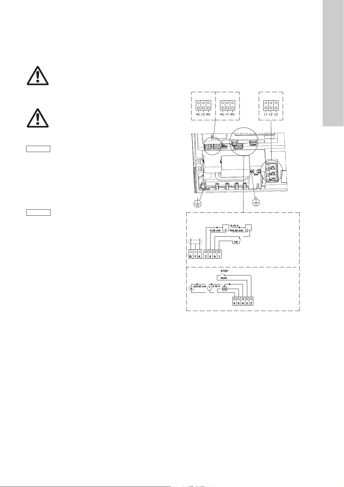
Page 11

1987
BYA
0-10 V
0/4-20 mA
4-20 mA
1/0
NC
CNO
L1 L2 L3
10K
RUN
STOP
65432
0/4-20 mA
0-10 V
1: Digital input
9: GND (frame)
8: +24 V
7: Sensor input
B: RS-485B
Y: Screen
A: RS-485A
6: GND (frame)
5: +10 V
4: Setpoint input
3: GND (frame)
2: Start/stop
Group 1
Group 3
Group 2
0-10 V
Group 4
Group 2
Group 3
1: Digital input
9: GND (frame)
8: +24 V
7: Sensor input
B: RS-485B
Y: Screen
A: RS-485A
6: GND (frame)
5: +10 V
4: Setpoint input
3: GND (frame)
2: Start/stop
Group 1
0/4-20 mA
0/1
BYA
0/4-20 mA 0-10 V
4-20 mA
STOP
RUN
10K
1987
NOCNC
L3L2L1
English (GB)
Fig. 8 Connection terminals - TPE, NKE, NKGE and NBE,
NBGE
TM02 8414 5103
65432
Fig. 9 Connection terminals - TPED
A galvanic separation must fulfil the requirements for reinforced
insulation including creepage distances and clearances specified
in EN 60335.
5.3 Electrical connection - three-phase pumps,
11-22 kW
Warnin g
The user or the installer is responsible for the
installation of correct earthing and protection
according to current national and local
standards. All operations must be carried out by
qualified personnel.
Warnin g
Never make any connections in the pump
terminal box unless all electric supply circuits
have been switched off for at least 5 minutes.
Note for instance that the signal relay may be
connected to an external supply which is still
connected when the mains supply is
disconnected.
Warning
The surface of the terminal box may be above
70 °C when the pump is operating.
TM03 0125 4104
11
Page 12

5.3.1 Preparation
L1
L2
L3
L2
L1
L3
PE
ELCB
ELCB
Torques, terminals L1-L3:
Min. torque: 2.2 Nm
Max. torque: 2.8 Nm
English (GB)
Before connecting the E-pump to the mains, take the issues
illustrated in the figure below into consideration.
Fig. 10 Mains-connected pump with mains switch, backup
fuses, additional protection and protective earthing
5.3.2 Protection against electric shock - indirect contact
Warning
The pump must be earthed in accordance with
national regulations.
As the leakage current of 11-22 kW motors is
> 10 mA, take extra precautions when earthing
these motors.
EN 61800-5-1 specifies that the pump must be stationary and
installed permanently when the leakage current is > 10 mA.
One of the following requirements must be fulfilled:
• A single protective earth conductor having a cross-sectional
area of min. 10 mm
2
copper.
5.3.3 Backup fuses
For recommended fuse sizes, see section 21.1 Supply voltage.
5.3.4 Additional protection
If the pump is connected to an electric installation where an earth
leakage circuit breaker (ELCB) is used as additional protection,
the circuit breaker must be of a type marked with the following
symbols:
TM00 9270 4696
This circuit breaker is type B.
The total leakage current of all the electrical equipment in the
installation must be taken into account.
The leakage current of the motor in normal operation can be seen
in section 21.3 Leakage current.
During start and at asymmetrical supply systems, the leakage
current can be higher than normal and may cause the ELCB to
trip.
5.3.5 Motor protection
The pump requires no external motor protection. The motor
incorporates thermal protection against slow overloading and
blocking (IEC 34-11, TP 211).
5.3.6 Protection against mains voltage transients
The pump is protected against mains voltage transients in
accordance with EN 61800-3 and is capable of withstanding a
VDE 0160 pulse.
The pump has a replaceable varistor which is part of the transient
protection.
Over time this varistor will be worn and need to be replaced.
When the time for replacement has come, R100 and PC Tool
E-products will indicate this as a warning. See section
18. Maintenance and service.
5.3.7 Supply voltage and mains
3 x 380-480 V - 10 %/+ 10 %, 50/60 Hz, PE.
The supply voltage and frequency are marked on the pump
nameplate. Make sure that the motor is suitable for the power
supply of the installation site.
The wires in the terminal box must be as short as possible.
Excepted from this is the protective earth conductor which must
be so long that it is the last one to be disconnected in case the
cable is inadvertently pulled out of the cable entry.
Fig. 11 Connection of a single protective earth conductor
using one of the conductors of a 4-core mains cable
(with cross-sectional area of min. 10 mm
2
)
• Two protective earth conductors of the same cross-sectional
area as the mains conductors, with one conductor connected
to an additional earth terminal in the terminal box.
Fig. 12 Connection of two protective earth conductors using
two of the conductors of a 5-core mains cable
Protective earth conductors must always have a yellow/green
(PE) or yellow/green/blue (PEN) colour marking.
12
TM04 3021 3508TM03 8606 2007
TM03 8605 2007 - TM04 3048 3508
Fig. 13 Mains connection
Page 13
Cable glands
Caution
Note
1: Digital input
9: GND (frame)
8: +24 V
7: Sensor input
B: RS-485B
Y: Scree n
A: RS-485A
6: GND (frame)
5: +10 V
4: Setpoint input
3: GND (frame)
2: Start/stop
Group 1
Group 2
Group 3
Cable glands comply with EN 50626.
• 1 x M40 cable gland, cable diameter ∅16-∅28
• 1 x M20 cable gland, cable diameter ∅9-∅17
• 2 x M16 cable gland, cable diameter ∅4-∅10
• 2 x M16 knock-out cable entries.
Warning
If the supply cable is damaged, it must be
replaced by qualified personnel.
Grid types
Three-phase E-pumps can be connected to all grid types.
Warning
Do not connect three-phase E-pumps to a mains
supply with a voltage between phase and earth of
more than 440 V.
5.3.8 Start/stop of pump
The number of starts and stops via the mains
voltage must not exceed 4 times per hour.
When the pump is switched on via the mains, it will start after
approx. 5 seconds.
If a higher number of starts and stops is desired, use the input for
external start/stop when starting/stopping the pump.
When the pump is switched on via an external on/off switch, it will
start immediately.
5.3.9 Connections
Group 4: Communication cable (8-pin male socket) -
only TPED
The communication cable is connected to the socket in
group 4. The cable ensures communication between the two
pumps, whether one or two pressure sensors are connected.
See section 5.6 Communication cable for TPED pumps.
The selector switch in group 4 enables changeover between
the operating modes "alternating operation" and "standby
operation". See description in section 6.2.1 Additional
operating modes - TPED pumps.
English (GB)
If no external on/off switch is connected,
connect terminals 2 and 3 using a short wire.
As a precaution, the wires to be connected to the following
connection groups must be separated from each other by
reinforced insulation in their entire lengths:
Group 1: Inputs
• start/stop, terminals 2 and 3
• digital input, terminals 1 and 9
• setpoint input, terminals 4, 5 and 6
• sensor input, terminals 7 and 8
• GENIbus, terminals B, Y and A
All inputs (group 1) are internally separated from the mains-
conducting parts by reinforced insulation and galvanically
separated from other circuits.
All control terminals are supplied with protective extra-low
voltage (PELV), thus ensuring protection against electric
shock.
Group 2: Output (relay signal, terminals NC, C, NO)
The output (group 2) is galvanically separated from other
circuits. Therefore, the supply voltage or protective extra-low
voltage can be connected to the output as desired.
Group 3: Mains supply (terminals L1, L2, L3)
TM03 8608 2007
Fig. 14 Connection terminals - TPE, NKE, NKGE and NBE,
NBGE
13
Page 14

English (GB)
Group 4Group 2 Group 3
1: Digital input
9: GND (frame)
8: +24 V
7: Sensor input
B: RS-485B
Y: Screen
A: RS-485A
6: GND (frame)
5: +10 V
4: Setpoint input
3: GND (frame)
2: Start/stop
Group 1
A
Y
B
A
Y
B
1
2
3
1
2
3
Pump
A
Y
B
A
Y
B
1
2
1
2
Pump
Jumper
White label
Master end
Slave end
5.5 Bus connection cable
5.5.1 New installations
For the bus connection, use a screened 3-core cable with a
conductor cross-section of min. 0.2 mm
• If the pump is connected to a unit with a cable clamp which is
identical to the one on the pump, connect the screen to this
cable clamp.
• If the unit has no cable clamp as shown in fig. 17, leave the
screen unconnected at this end.
Fig. 17 Connection with screened 3-core cable
5.5.2 Replacing an existing pump
• If a screened 2-core cable is used in the existing installation,
connect it as shown in fig. 18.
2
and max. 1.5 mm2.
TM02 8841 0904TM02 8842 0904TM02 5991 4702TM04 5497 3309
Fig. 15 Connection terminals - TPED
A galvanic separation must fulfil the requirements for reinforced
insulation including creepage distances and clearances specified
in EN 61800-5-1.
5.4 Signal cables
• Use screened cables with a conductor cross-section of
min. 0.5 mm
digital input, setpoint and sensor signals.
• Connect the screens of the cables to frame at both ends with
good frame connection. The screens must be as close as
possible to the terminals. See fig. 16.
Fig. 16 Stripped cable with screen and wire connection
• Always tighten screws for frame connections whether a cable
is fitted or not.
• Make the wires in the pump terminal box as short as possible.
14
2
and max. 1.5 mm2 for external on/off switch,
Fig. 18 Connection with screened 2-core cable
• If a screened 3-core cable is used in the existing installation,
follow the instructions in section 5.5.1 New installations.
TM03 9134 3407TM02 1325 0901
5.6 Communication cable for TPED pumps
The communication cable is connected between the two terminal
boxes. The screen of the cable is connected to the frame at both
ends with a good frame connection.
Fig. 19 Communication cable
The communication cable has a master end and a slave end as
shown in fig. 20.
Fig. 20 Master end and slave end
On pumps with factory-fitted sensor, the master end and the
sensor are connected to the same terminal box.
When the power supply to the two pumps has been switched off
for 40 seconds and switched on again, the pump connected to the
master end will start up first.
Page 15

5.6.1 Connection of two sensors
Jumper
White label
Master end
Slave end
Jumper
White label
Master end
Slave end
Q
H
Max.
Min.
The sensor signal is copied to the other pump through the red
wire of the communication cable.
If, optionally, two sensors are connected (one sensor to each
terminal box), cut the red wire. See fig. 21.
6. Modes
Grundfos E-pumps are set and controlled according to operating
and control modes.
6.1 Overview of modes
Fig. 21 Elimination of copied sensor signal
5.6.2 Elimination of "alternating operation" and
"standby operation"
If "alternating operation" and "standby operation" are not desired,
but the copied sensor signal (one sensor signal to two pumps) is
desired, cut the green wire. See fig. 22.
Operating modes Normal Stop Min. Max.
Control modes Uncontrolled Controlled
Constant
TM04 5495 3309TM04 5496 3309
1) In this example the pump is equipped with a differential
curve
Constant
pressure
pressure sensor. The pump may also be equipped with e.g.
a temperature sensor in which case the description would be
constant temperature in control mode controlled.
6.2 Operating mode
When the operating mode is set to Normal, the control mode can
be set to controlled or uncontrolled. See section 6.3 Control
mode.
The other operating modes that can be selected are Stop, Min. or
Max.
• Stop: The pump has been stopped.
• Min.: The pump is operating at its minimum speed.
• Max.: The pump is operating at its maximum speed.
Figure 23 is a schematic illustration of min. and max. curves.
English (GB)
1)
Fig. 22 Elimination of "alternating operation" and
"standby operation"
5.6.3 Elimination of TPED function
If "alternating operation" and "standby operation" as well as the
copied sensor signal are not desired, remove the communication
cable completely.
TM00 5547 0995
Fig. 23 Min. and max. curves
The max. curve can for instance be used in connection with the
venting procedure during installation.
The min. curve can be used in periods in which a minimum flow is
required.
If the power supply to the pump is disconnected, the mode setting
will be stored.
The remote control R100 offers additional possibilities of setting
and status displays. See section 8. Setting by means of R100.
15
Page 16

6.2.1 Additional operating modes - TPED pumps
Note
Q
H
set
H
Q
H
Controlled
Uncontrolled
Buttons
Indicator lights
Light fields
Light fields
Buttons
Indicator
lights
English (GB)
The TPED pumps offer the following additional operating modes:
• Alternating operation. Pump operation alternates every
24 hours. If the duty pump stops due to a fault, the other pump
will start.
• Standby operation. One pump is operating continuously.
In order to prevent seizing-up, the other pump is started
10 sec. every 24 hours. If the duty pump stops due to a fault,
the other pump will start.
Select the operating mode by means of the selector switch in the
terminal box. See figs 5, 9 and 15.
The selector switch enables changeover between the operating
modes "alternating operation" (left position) and "standby
operation" (right position).
The switches in the two terminal boxes must be set to the same
position. If the switches are positioned differently, the pump will
be in "standby operation".
Twin-head pumps can be set and operated in the same way as
single-head pumps. The duty pump uses its setpoint setting,
whether it is made by means of the control panel, via the R100 or
via bus.
Both pumps should be set to the same setpoint
and control mode. Di ffer en t se t tin g s wi ll r e su l t in
different operation when changing between the
two pumps.
If the power supply to the pump is disconnected, the pump setting
will be stored.
The remote control R100 offers additional possibilities of setting
and status displays. See section 8. Setting by means of R100.
6.4 Factory setting
TPE, NKE, NKGE and NBE, NBGE pumps
The pumps have been factory-set to uncontrolled operation.
The setpoint value corresponds to 100 % of the maximum pump
performance (see data sheet for the pump).
In sections 8.1 Menu OPERATION and 8.3 Menu
INSTALLATION, the factory-setting is marked with bold-faced
type under each individual display.
TPED pumps
The pumps have been factory-set to uncontrolled operation and
the additional operating mode "alternating operation".
The setpoint value corresponds to 100 % of the maximum pump
performance (see data sheet for the pump).
In sections 8.1 Menu OPERATION and 8.3 Menu
INSTALLATION, the factory-setting is marked with bold-faced
type under each individual display.
7. Setting by means of control panel
Warning
At high system temperatures, the pump may be
so hot that only the buttons should be touched to
avoid burns.
The pump control panel, see fig. 25 or 26, incorporates the
following buttons and indicator lights:
• Buttons, and , for setpoint setting.
• Light fields, yellow, for indication of setpoint.
• Indicator lights, green (operation) and red (fault).
6.3 Control mode
The pump can be set to two control modes, i.e.
• controlled
• uncontrolled.
In control mode controlled, the pump will adjust its performance
to the desired setpoint for the control parameter (pressure,
differential pressure, temperature, differential temperature or
flow).
In control mode uncontrolled, the pump will operate according to
the constant curve set.
Fig. 24 Pump in control mode controlled (differential pressure
control) and in control mode uncontrolled
The pumps have been factory-set to control mode uncontrolled.
See section 6.4 Factory setting.
TM00 7600 0304TM02 8513 0304
Fig. 25 Control panel, single-phase pumps
TM00 7668 0404
Fig. 26 Control panel, three-phase pumps
16
Page 17

7.1 Setpoint setting
Note
H
Q
H
Q
H
Q
The setpoint can only be set when the operating
mode is Normal.
Set the desired setpoint by pressing the button or .
The light fields on the control panel will indicate the setpoint set.
See examples in sections 7.1.1 and 7.1.2.
7.1.1 Pump in control mode controlled (differential pressure
control)
Example
Figure 27 shows that the light fields 5 and 6 are activated,
indicating a desired setpoint of 3.4 m. The sensor measuring
range is 0 to 6 m. The setting range is equal to the sensor
measuring range (see sensor nameplate).
Fig. 27 Setpoint set to 3.4 m (differential pressure control)
7.1.2 Pump in control mode uncontrolled
Example
In control mode uncontrolled, the pump performance is set within
the range from min. to max. curve, fig. 28.
7.3 Setting to min. curve duty
Press continuously to change to the min. curve of the pump
(bottom light field flashes).
To change back, press continuously until the desired setpoint
is indicated.
Fig. 30 Min. curve duty
7.4 Start/stop of pump
Start the pump by continuously pressing until the desired
setpoint is indicated.
Stop the pump by continuously pressing until none of the light
fields are activated and the green indicator light flashes.
8. Setting by means of R100
TM03 5845 4006TM00 7746 1304TM00 7345 1304
The pump is designed for wireless communication with the
Grundfos remote control R100.
English (GB)
TM00 7346 1304TM02 0936 0501
Fig. 31 R100 communicating with the pump via infra-red light
During communication, the R100 must be pointed at the control
panel. When the R100 communicates with the pump, the red
indicator light will flash rapidly. Keep pointing the R100 at the
control panel until the red LED diode stops flashing.
Fig. 28 Pump performance setting, control mode uncontrolled
7.2 Setting to max. curve duty
Press continuously to change to the max. curve of the pump
(top light field flashes).
To change back, press continuously until the desired setpoint
is indicated.
Fig. 29 Max. curve duty
The R100 offers setting and status displays for the pump.
The displays are divided into four parallel menus, fig. 32:
0. GENERAL (see operating instructions for the R100)
1. OPERATION
2. STATUS
3. INSTALLATION
The figure above each individual display in fig. 32 refers to the
section in which the display is described.
17
Page 18

English (GB)
0. GENERAL 1. OPERATION 2. STATUS 3. INSTALLATION
8.1.1 8.2.1 8.3.1 8.3.9
8.1.2 8.2.2 8.3.2 8.3.10 (3)
8.1.3 8.2.3 8.3.3 8.3.11 (3)
8.1.3 (3) 8.2.4 8.3.4 (1) 8.3.12 (3)
8.1.4 8.2.5 8.3.4 - 1 (2)
8.2.6 8.3.4 - 2 (2)
8.1.4 (3) 8.2.7 (2) 8.3 .5
8.2.8 (2) 8.3.6
8.2.9 (3) 8.3.7
(1)This display only appears for pumps up to 7.5 kW.
(2)This display only appears for three-phase pumps, 11-22 kW.
(3)This display only appears for three-phase pumps.
Fig. 32 Menu overview
18
8.3.8
Page 19

8.1 Menu
Note
The first display in the menu is this.
8.1.1 Setpoint
Set the desired setpoint in this display.
In control mode controlled, the setting range is equal to the
sensor measuring range, e.g. 0 to 25 m.
In control mode uncontrolled, the setpoint is set in % of the
maximum performance. The setting range will lie between the
min. and max. curves.
If the pump is connected to an external setpoint signal, the value
in this display will be the maximum value of the external setpoint
signal. See section 12. External setpoint signal.
Setpoint and external signal
The setpoint cannot be set if the pump is controlled via external
signals (Stop, Min. curve or Max. curve). The R100 will give this
warning: External control!
Check if the pump is stopped via terminals 2-3 (open circuit) or
set to min. or max. via terminals 1-3 (closed circuit).
See section 10. Priority of settings.
Setpoint and bus communication
The setpoint cannot be set either if the pump is controlled from an
external control system via bus communication. The R100 will
give this warning: Bus control!
To override bus communication, disconnect the bus connection.
See section 10. Priority of settings.
OPERATION
Setpoint set
Actual setpoint
Actual value
8.1.2 Operating mode
Set one of the following operating modes:
• Max.
• Normal (duty)
•Min.
•Stop.
The operating modes can be set without changing the setpoint
setting.
8.1.3 Fault indications
In E-pumps, faults may result in two types of indication: alarm or
warning.
An "alarm" fault will activate an alarm indication in the R100 and
cause the pump to change operating mode, typically to stop.
However, for some faults resulting in alarm, the pump is set to
continue operating even if there is an alarm.
A "warning" fault will activate a warning indication in the R100,
but the pump will not change operating or control mode.
The indication "Warning" only applies to threephase pumps.
Alarm
In case of alarm, the cause will appear in this display.
Possible causes:
• No alarm indication
• Too high motor temperature
• Undervoltage
• Mains voltage asymmetry (11-22 kW)
• Overvoltage
• Too many restarts (after faults)
• Overload
• Underload (11-22 kW)
• Sensor signal outside signal range
• Setpoint signal outside signal range
• External fault
• Other fault.
If the pump has been set up to manual restart, an alarm indication
can be reset in this display if the cause of the fault has
disappeared.
English (GB)
19
Page 20

Warning (only three-phase pumps)
English (GB)
In case of warning, the cause will appear in this display.
Possible causes:
• No warning indication
• Sensor signal outside signal range
• Relubricate motor bearings (only 11-22 kW), see section 18.2
• Replace motor bearings. See section 18.3
• Replace varistor (only 11-22 kW), see section 18.4.
A warning indication will disappear automatically once the fault
has been remedied.
8.1.4 Fault log
For both fault types, alarm and warning, the R100 has a log
function.
Alarm log
8.2 Menu STATUS
The displays appearing in this menu are status displays only. It is
not possible to change or set values.
The displayed values are the values that applied when the last
communication between the pump and the R100 took place. If a
status value is to be updated, point the R100 at the control panel
and press "OK".
If a parameter, e.g. speed, should be called up continuously,
press "OK" constantly during the period in which the parameter in
question should be monitored.
The tolerance of the displayed value is stated under each display.
The tolerances are stated as a guide in % of the maximum values
of the parameters.
8.2.1 Actual setpoint
Tolerance: ± 2 %
This display shows the actual setpoint and the external setpoint in
% of the range from minimum value to the setpoint set.
See section 12. External setpoint signal.
8.2.2 Operating mode
In case of "alarm" faults, the last five alarm indications will appear
in the alarm log. "Alarm log 1" shows the latest fault, "Alarm log 2"
shows the latest fault but one, etc.
The example above gives this information:
• the alarm indication Undervoltage
• the fault code (73)
• the number of minutes the pump has been connected to the
power supply after the fault occurred, 8 min.
Warning log (only three-phase pumps)
In case of "warning" faults, the last five warning indications will
appear in the warning log. "Warning log 1" shows the latest fault,
"Warning log 2" shows the latest fault but one, etc.
The example above gives this information:
• the warning indication Relubricate motor bearings
• the fault code (240)
• the number of minutes the pump has been connected to the
power supply since the fault occurred, 30 min.
This display shows the actual operating mode (Stop, Min.,
Normal (duty) or Max.). Furthermore, it shows where this
operating mode was selected (R100, Pump, Bus or External).
8.2.3 Actual value
This display shows the value actually measured by a connected
sensor.
If no sensor is connected to the pump, "-" will appear in the
display.
8.2.4 Speed
Tolerance: ± 5 %
The actual pump speed will appear in this display.
20
Page 21

8.2.5 Power input and power consumption
Note
Tolerance: ± 10 %
This display shows the actual pump input power from the mains
supply. The power is displayed in W or kW.
The pump power consumption can also be read from this display.
The value of power consumption is an accumulated value
calculated from the pump’s birth and it cannot be reset.
8.2.6 Operating hours
Tolerance: ± 2 %
The value of operating hours is an accumulated value and cannot
be reset.
8.2.7 Lubrication status of motor bearings (only 11-22 kW)
8.2.9 Time till replacement of motor bearings (only three-phase pumps)
When the motor bearings have been relubricated, a prescribed
number of times stored in the controller, the display in section 8.2.8
will be replaced by the display below.
English (GB)
This display shows when to replace the motor bearings.
The controller monitors the operating pattern of the pump and
calculates the period between bearing replacements.
The displayable values are these:
• in 2 years
• in 1 year
• in 6 months
• in 3 months
• in 1 month
• in 1 week
• Now!
8.3 Menu INSTALLATION
8.3.1 Control mode
This display shows how many times the motor bearings have
been relubricated and when to replace the motor bearings.
When the motor bearings have been relubricated, confirm this
action in the INSTALLATION menu. See section 8.3.11 Confirming
relubrication/replacement of motor bearings (only three-phase
pumps). When relubrication is confirmed, the figure in the above
display will be increased by one.
8.2.8 Time till relubrication of motor bearings (only 11-22 kW)
This display shows when to relubricate the motor bearings.
The controller monitors the operating pattern of the pump and
calculates the period between bearing relubrications. If the
operating pattern changes, the calculated time till relubrication
may change as well.
The displayable values are these:
• in 2 years
• in 1 year
• in 6 months
• in 3 months
• in 1 month
• in 1 week
• Now!
Select one of the following control modes (see fig. 24):
• Controlled
• Uncontrolled.
How to set the desired performance, see section 8.1.1 Setpoint.
If the pump is connected to a bus, the control
mode cannot be selected via the R100.
See section 13. Bus signal.
8.3.2 Controller
E-pumps have a factory default setting of gain (K
time (T
). However, if the factory setting is not the optimum
i
) and integral
p
setting, the gain and the integral time can be changed in the
display below.
•The gain (K
• The integral time (T
3600 s. If 3600 s is selected, the controller will function as a
) can be set within the range from 0.1 to 20.
p
) can be set within the range from 0.1 to
i
P controller.
• Furthermore, it is possible to set the controller to inverse
control, meaning that if the setpoint is increased, the speed
will be reduced. In the case of inverse control, the gain (K
p
must be set within the range from -0.1 to -20.
)
21
Page 22

The table below shows the suggested controller settings:
Δp
L1 [m]
Δp
p
Q
t
L
2
[m]
Δt
L2 [m]
L2 [m]
t
Note
English (GB)
K
p
System/application
Heating
system
1)
0.5 0.5
Cooling
system
General rules of thumb:
• If the controller is too slow-reacting, increase K
.
p
• If the controller is hunting or unstable, dampen the system by
T
2)
i
reducing K
8.3.3 External setpoint
or increasing Ti.
p
< 5 m: 0.5
L
1
L
0.5
> 5 m: 3
1
L
> 10 m: 5
1
0.5 0.5
0.5 0.5
0.5 - 0.5 10 + 5L
0.5 10 + 5L
The input for external setpoint signal can be set to different signal
types.
Select one of the following types:
• 0-10 V
• 0-20 mA
• 4-20 mA
• Not active.
If Not active is selected, the setpoint set by means of the R100 or
on the control panel will apply.
If one of the signal types is selected, the actual setpoint is
influenced by the signal connected to the external setpoint input.
See section 12. External setpoint signal.
8.3.4 Signal relay
Pumps up to 7.5 kW have one signal relay. The factory setting of
the relay will be Fault.
2
Pumps of 11-22 kW have two signal relays. Signal relay 1 is
factory-set to Alarm and signal relay 2 to Warning.
In one of the displays below, select in which operating situation
the signal relay should be activated.
Up to 7.5 kW
2
0.5 - 0.5 30 + 5L
1. Heating systems are systems in which an increase in pump
performance will result in a rise in temperature at the sensor.
2. Cooling systems are systems in which an increase in pump
performance will result in a drop in temperature at the sensor.
L
= Distance in [m] between pump and sensor.
1
= Distance in [m] between heat exchanger and sensor.
L
2
How to set the PI controller
For most applications, the factory setting of the controller
constants K
and Ti will ensure optimum pump operation.
p
However, in some applications an adjustment of the controller
may be needed.
Proceed as follows:
1. Increase the gain (K
Instability can be seen by observing if the measured value
) until the motor becomes unstable.
p
starts to fluctuate. Furthermore, instability is audible as the
motor starts hunting up and down.
Some systems, such as temperature controls, are slowreacting, meaning that it may be several minutes before the
motor becomes unstable.
2. Set the gain (K
motor unstable. This is the correct setting of the gain.
3. Reduce the integral time (T
unstable.
4. Set the integral time (T
) to half the value of the value which made the
p
) until the motor becomes
i
) to twice the value which made the
i
motor unstable. This is the correct setting of the integral time.
2
• Ready
• Fault
• Operation
• Pump running (only three-phase pumps up to 7.5 kW)
• Warni ng (only three-phase pumps up to 7.5 kW).
11-22 kW 11-22 kW
• Ready
• Alarm
• Operation
• Pump running
• Warni ng
• Relubricate.
• Ready
• Alarm
• Operation
• Pump running
• Warning
• Relubricate.
Fault and Alarm cover faults resulting in Alarm.
Warning covers faults resulting in Warning.
Relubricate covers only that one individual event.
For distinction between alarm and warning,
see section 8.1.3 Fault indications.
For further information, see section 15. Indicator lights and signal
relay.
22
Page 23

8.3.5 Buttons on pump
Note
Q
H
100 %
Max. curve
12 %
Min. curve
Operating rang
e
The operating buttons and on the control panel can be set
to these values:
• Active
• Not active.
When set to Not active (locked), the buttons do not function.
Set the buttons to Not active if the pump should be controlled via
an external control system.
8.3.6 Pump number
A number between 1 and 64 can be allocated to the pump. In the
case of bus communication, a number must be allocated to each
pump.
8.3.7 Digital input
8.3.9 Operating range
English (GB)
How to set the operating range:
• Set the min. curve within the range from max. curve to 12 % of
maximum performance. The pump has been factory-set to
24 % of maximum performance.
• Set the max. curve within the range from maximum
performance (100 %) to min. curve.
The area between the min. and max. curves is the operating
range.
The digital input of the pump (terminal 1, fig. 4, 8 or 14) can be
set to different functions.
Select one of the following functions:
• Min. (min. curve)
• Max. (max. curve).
The selected function is activated by closing the contact between
terminals 1 and 9. See figs 4, 8 and 14.
See also section 11.2 Digital input.
Min.:
When the input is activated, the pump will operate according to
the min. curve.
Max.:
When the input is activated, the pump will operate according to
the max. curve.
8.3.8 Sensor
TM00 7747 1896
Fig. 33 Setting of the min. and max. curves in % of maximum
performance
8.3.10 Motor bearing monitoring (only three-phase pumps)
The motor bearing monitoring function can be set to these values:
• Active
• Not active.
When the function is set to Active, a counter in the controller will
start counting the mileage of the bearings.
See section 8.2.7 Lubrication status of motor bearings
(only 11-22 kW).
The counter will continue counting even if the
function is switched to Not active, but a warning
will not be given when it is time for relubrication.
When the function is switched to Active again,
the accumulated mileage will again be used to
calculate the relubrication time.
The setting of the sensor is only relevant in the case of controlled
operation.
Select among the following values:
• Sensor output signal
0-10 V
0-20 mA
4-20 mA
• Unit of measurement of sensor:
bar, mbar, m, kPa, psi, ft, m³/h, m³/s, l/s, gpm, °C, °F, %
• Sensor measuring range.
23
Page 24

8.3.11 Confirming relubrication/replacement of motor
Note
Note
English (GB)
bearings (only three-phase pumps)
This function can be set to these values:
• Relubricated (only 11-22 kW)
• Replaced
• Nothing done.
When the bearing monitoring function is Active, the controller will
give a warning indication when the motor bearings are due to be
relubricated or replaced. See section 8.1.3 Fault indications.
When the motor bearings have been relubricated or replaced,
confirm this action in the above display by pressing "OK".
Relubricated cannot be selected for a period of
time after confirming relubrication.
8.3.12 Standstill heating (only three-phase pumps)
The standstill heating function can be set to these values:
• Active
• Not active.
When the function is set to Active, a low voltage will be applied to
the motor windings when the pump is not operating. The applied
voltage will ensure that sufficient heat is generated to avoid
condensation in the motor.
9. Setting by means of PC Tool E-products
Special setup requirements differing from the settings available
via the R100 require the use of Grundfos PC Tool E-products.
This again requires the assistance of a Grundfos service
technician or engineer. Contact your local Grundfos company for
more information.
10. Priority of settings
The priority of settings depends on two factors:
1. control source
2. settings.
1. Control source
Control panel
R100
External signals
(external setpoint signal, digital inputs, etc.)
Communication from another control system
via bus
2. Settings
• Operating mode Stop
• Operating mode Max. (max. curve)
• Operating mode Min. (min. curve)
• Setpoint setting.
An E-pump can be controlled by different control sources at the
same time, and each of these sources can be set differently.
Consequently, it is necessary to set an order of priority of the
control sources and the settings.
If two or more settings are activated at the same
time, the pump will operate according to the
function with the highest priority.
Priority of settings without bus communication
Priority Control panel or R100 External signals
1 Stop
2 Max.
3 Stop
4 Max.
5 Min. Min.
6 Setpoint setting Setpoint setting
Example: If the E-pump has been set to operating mode Max.
(max. frequency) via an external signal, such as digital input, the
control panel or R100 can only set the E-pump to operating mode
Stop.
24
Page 25
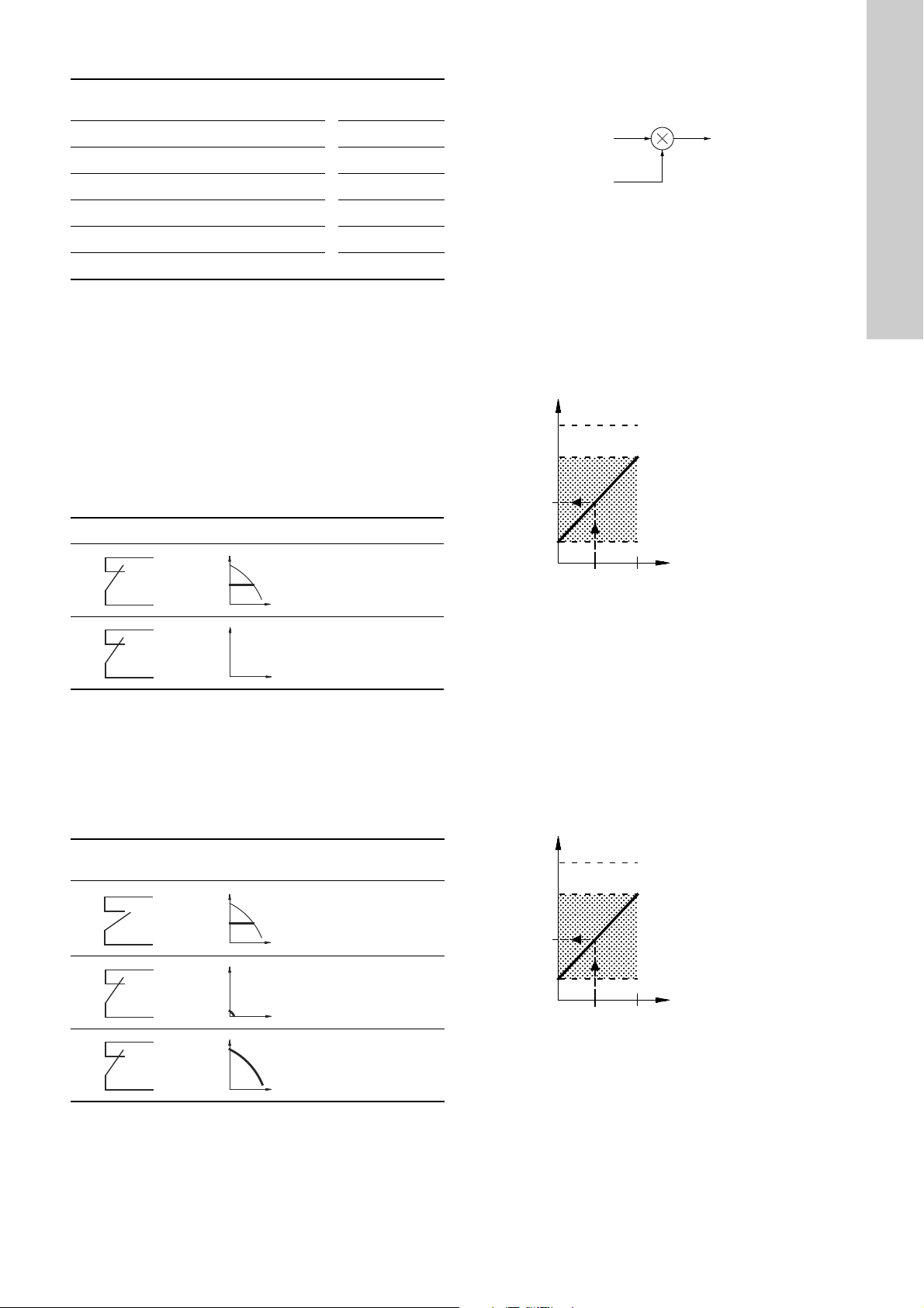
Priority of settings with bus communication
Q
H
Q
H
Q
H
Q
H
Q
H
Setpoint
External setpoint
Actual setpoint
0 10 V
0 20 mA
4 20 mA
Actual setpoint
Sensor
max
Setpoint set by means of
control panel, R100 or
PC Tool E-products
Sensor
min
External setpoint signal
Actual
setpoint
0 10 V
0 20 mA
4 20 mA
Actual setpoint
Max
curve
Setpoint set by means of
control panel, R100 or
PC Tool E-products
Min
curve
External setpoint signal
Actual
setpoint
Priority
Control panel
or R100
External
signals
Bus
communication
1 Stop
2 Max.
3 Stop Stop
4 Max.
5 Min.
6 Setpoint setting
Example: If the E-pump is operating according to a setpoint set
via bus communication, the control panel or R100 can set the
E-pump to operating mode Stop or Max., and the external signal
can only set the E-pump to operating mode Stop.
11. External forced-control signals
The pump has inputs for external signals for these forced-control
functions:
• Start/stop of pump
• Digital function.
11.1 Start/stop input
Functional diagram: Start/stop input
12. External setpoint signal
The setpoint can be remote-set by connecting an analogue signal
transmitter to the input for the setpoint signal (terminal 4).
Fig. 34 Actual setpoint as a product (multiplied value) of
setpoint and external setpoint
Select the actual external signal, 0-10 V, 0-20 mA, 4-20 mA, via
the R100. See section 8.3.3 External setpoint.
If control mode uncontrolled is selected by means of the R100,
the pump can be controlled by any controller.
In control mode controlled, the setpoint can be set externally
within the range from sensor
by means of the R100.
to the setpoint set on the pump or
min
English (GB)
TM03 8601 2007TM02 8988 1304TM02 8988 1304
Start/stop (terminals 2 and 3)
Normal duty
Stop
11.2 Digital input
By means of the R100, one of the following functions can be
selected for the digital input:
• Normal duty
• Min. curve
• Max. curve.
Functional diagram: Input for digital function
Digital function
(terminals 1 and 9)
Normal duty
Fig. 35 Relation between the actual setpoint and the external
setpoint signal in control mode controlled
Example: At a sensor
value of 0 m, a setpoint set of 20 m and
min
an external setpoint of 80 %, the actual setpoint will be as follows:
= (H
- H
H
actual
set
min
) x %
external setpoint
+ H
min
= (20 - 0) x 80 % + 0
= 16 m
In control mode uncontrolled, the setpoint can be set externally
within the range from the min. curve to the setpoint set on the
pump or by means of the R100.
Min. curve
Max. curve
Fig. 36 Relation between the actual setpoint and the external
setpoint signal in control mode open loop
25
Page 26

13. Bus signal
Note
Green Red
Green
Red
Green Red
Green
Red
Green
Red
English (GB)
The pump supports serial communication via an RS-485 input.
The communication is carried out according to the Grundfos bus
protocol, GENIbus protocol, and enables connection to a building
management system or another external control system.
Operating parameters, such as setpoint, operating mode, etc. can
be remote-set via the bus signal. At the same time, the pump can
provide status information about important parameters, such as
actual value of control parameter, input power, fault indications,
etc.
Contact Grundfos for further details.
If a bus signal is used, the number of settings
available via the R100 will be reduced.
14. Other bus standards
Grundfos offers various bus solutions with communication
according to other standards.
Contact Grundfos for further details.
15. Indicator lights and signal relay
The operating condition of the pump is indicated by the green and
red indicator lights fitted on the pump control panel and inside the
terminal box. See figs 37 and 38.
TM00 7600 0304
Fig. 37 Position of indicator lights on single-phase pumps
TM02 8513 0304
Fig. 38 Position of indicator lights on three-phase pumps
Besides, the pump incorporates an output for a potential-free
signal via an internal relay.
For signal relay output values, see section 8.3.4 Signal relay.
TM02 0838 0203
TM02 9036 4404
TM03 9063 3307
26
Page 27

The functions of the two indicator lights and the signal relay are as shown in the following table:
NCNOCNCNOCNCNOCNCNO
C
NCNO
C
C
NO NCCNO NCCNO NC
NCNO
C
C
NO NCCNO NC
NCNO
C
C
NO NC
NCNOCNCNOCNCNO
C
C
NO NCCNO NCCNO NCCNO NC
C
NO NC
NCNO
C
C
NO NC
NCNO
C
Caution
Caution
Indicator lights Signal relay activated during:
Fault
(red)
Operation
(green)
Fault/Alarm,
Warning and
Relubricate
Operating Ready
Pump
running
Description
Off Off The power supply has been switched off.
English (GB)
Off
Permanently
on
The pump is operating.
Off Flashing The pump has been set to stop.
The pump has stopped because of a
Fault/Alarm or is running with a Warning
Permanently
on
Off
or Relubricate indication.
If the pump was stopped, restarting will be
attempted (it may be necessary to restart
the pump by resetting the Fault
indication).
The pump is operating, but it has or has
had a Fault/Alarm allowing the pump to
continue operation or it is operating with a
Warning or Relubricate indication.
If the cause is "sensor signal outside
signal range", the pump will continue
Permanently onPermanently
on
operating according to the max. curve and
the fault indication cannot be reset until
the signal is inside the signal range.
If the cause is "setpoint signal outside
signal range", the pump will continue
operating according to the min. curve and
the fault indication cannot be reset until
the signal is inside the signal range.
Permanently
on
Flashing
Resetting of fault indication
A fault indication can be reset in one of the following ways:
• Briefly press the button or on the pump. This will not
change the setting of the pump.
A fault indication cannot be reset by means of or if the
buttons have been locked.
• Switch off the power supply until the indicator lights are off.
• Switch the external start/stop input off and then on again.
• Use the R100. See section 8.1.3 Fault indications.
When the R100 communicates with the pump, the red indicator
light will flash rapidly.
The pump has been set to stop, but it has
been stopped because of a Fault.
16. Insulation resistance
Up to 7.5 kW
Do not measure the insulation resistance of
motor windings or an installation incorporating
E-pumps using high voltage megging equipment,
as this may damage the built-in electronics.
11-22 kW
Do not measure the insulation resistance of an
installation incorporating E-pumps using high
voltage megging equipment, as this may damage
the built-in electronics.
The motor conductors can be disconnected
separately and the insulation resistance of the
motor windings can be tested.
27
Page 28

17. Emergency operation (only 11-22 kW)
Caution
English (GB)
Warning
Never make any connections in the pump
terminal box unless all electric supply circuits
have been switched off for at least 5 minutes.
Note for instance that the signal relay may be
connected to an external supply which is still
connected when the mains supply is
disconnected.
If the pump has stopped and it does not restart after you have
gone through normal remedies, the reason could be a faulty
frequency converter. If this is the case, it is possible to establish
emergency operation of the pump.
But before you change to emergency operation, we recommend
you to check these points:
• Check that the mains supply is OK.
• Check that control signals are working (start/stop signals).
• Check that all alarms have been reset.
• Make a resistance test on the motor windings (disconnect the
motor conductors from the terminal box).
If the pump still does not start, the frequency converter is faulty.
To establish emergency operation, proceed as follows:
1. Disconnect the three mains conductors, L1, L2, L3, from the
terminal box, but leave the protective earth conductor(s) in
position on the PE terminal(s).
3. Connect the conductors as shown in fig. 41.
TM04 0018 4807TM03 9121 3407TM03 9122 3407TM03 9123 3407
Fig. 41 How to switch an E-pump from normal operation to
emergency operation
Use the screws from the mains terminals and the nuts from the
motor terminals.
Fig. 39 Disconnecting the mains conductors
2. Disconnect the motor supply conductors, U/W1, V/U1, W/V1,
from the terminal box.
Fig. 42 Connecting the conductors
4. Insulate the three conductors from each other by means of
insulating tape or the like.
Fig. 43 Insulating the conductors
TM03 8607 2007TM03 9120 3407
Fig. 44 Insulated conductors
Fig. 40 Disconnecting the motor supply conductors
28
Warnin g
Do not bypass the frequency converter by
connecting the mains conductors to the U, V and
W terminals.
This may cause hazardous situations for
personnel as the high voltage potential of the
mains may be transferred to touchable
components in the terminal box.
Check the direction of rotation when starting up
after switching to emergency operation.
Page 29

18. Maintenance and service
Note
19. Technical data - single-phase pumps
18.1 Cleaning of the motor
Keep the motor cooling fins and fan blades clean to ensure
sufficient cooling of the motor and electronics.
18.2 Relubrication of motor bearings
Pumps up to 7.5 kW
The motor bearings are of the closed type and greased for life.
The bearings cannot be relubricated.
Pumps of 11-22 kW
The motor bearings are of the open type and must be relubricated
regularly.
The motor bearings are pre-lubricated on delivery. The built-in
bearing monitoring function will give a warning indication on the
R100 when the motor bearings are due to be relubricated.
Before relubrication, remove the bottom plug in
the motor flange and the plug in the bearing
cover to ensure that old and excess grease can
escape.
Quantity of grease
[ml]
Frame size
Drive end
(DE)
Non-drive end
(NDE)
MGE 160 13 13
MGE 180 15 15
When relubricating the first time, use the double quantity of
grease as the lubricating channel is still empty.
The recommended grease type is a polycarbamide-based
lubricating grease.
18.3 Replacement of motor bearings
Three-phase motors have built-in bearing monitoring function
which will give a warning indication on the R100 when the motor
bearings are due to be replaced.
18.4 Replacement of varistor (only 11-22 kW)
The varistor protects the pump against mains voltage transients.
If voltage transients occur, the varistor will be worn over time and
need to be replaced. The more transients, the more quickly the
varistor will be worn. When it is time to replace the varistor, R100
and PC Tool E-products will indicate this as a warning.
A Grundfos technician is required for replacement of the varistor.
Contact your local Grundfos company for assistance.
18.5 Service parts and service kits
For further information on service parts and service kits, visit
www.Grundfos.com, select country, select WebCAPS.
19.1 Supply voltage
1 x 200-240 V - 10 %/+ 10 %, 50/60 Hz - 2 %/+ 2 %, PE.
Cable: Max. 1.5 mm
Use min. 70 °C copper conductors only.
Recommended fuse size
Motor sizes up to 1.1 kW: Max. 10 A.
Standard as well as quick-blow or slow-blow fuses may be used.
2
/ 12 AWG.
19.2 Overload protection
The overload protection of the E-motor has the same
characteristic as an ordinary motor protector. As an example, the
E-motor can stand an overload of 110 % of I
for 1 min.
nom
19.3 Leakage current
Earth leakage current < 3.5 mA.
The leakage currents are measured in accordance with
EN 61800-5-1.
19.4 Inputs/outputs
Start/stop
External potential-free contact.
Voltage: 5 VDC.
Current: < 5 mA.
Screened cable: 0.5 - 1.5 mm
Digital
External potential-free contact.
Voltage: 5 VDC.
Current: < 5 mA.
Screened cable: 0.5 - 1.5 mm
Setpoint signals
• Potentiometer
0-10 VDC, 10 kΩ (via internal voltage supply).
Screened cable: 0.5 - 1.5 mm
Maximum cable length: 100 m.
• Voltage signal
0-10 VDC, R
Tolerance: + 0 %/- 3 % at maximum voltage signal.
> 50 kΩ.
i
Screened cable: 0.5 - 1.5 mm
Maximum cable length: 500 m.
• Current signal
DC 0-20 mA/4-20 mA, R
Tolerance: + 0 %/- 3 % at maximum current signal.
Screened cable: 0.5 - 1.5 mm
Maximum cable length: 500 m.
Sensor signals
• Voltage signal
0-10 VDC, R
Tolerance: + 0 %/- 3 % at maximum voltage signal.
> 50 kΩ (via internal voltage supply).
i
Screened cable: 0.5 - 1.5 mm
Maximum cable length: 500 m.
• Current signal
DC 0-20 mA/4-20 mA, R
Tolerance: + 0 %/- 3 % at maximum current signal.
Screened cable: 0.5 - 1.5 mm
Maximum cable length: 500 m.
Internal power supplies
• 10 V power supply for external potentiometer:
Max. load: 2.5 mA.
Short-circuit-protected.
• 24 V power supply for sensors:
Max. load: 40 mA.
Short-circuit-protected.
Signal relay output
Potential-free changeover contact.
Maximum contact load: 250 VAC, 2 A, cos φ 0.3 - 1.
Minimum contact load: 5 VDC, 10 mA.
Screened cable: 0.5 - 2.5 mm
Maximum cable length: 500 m.
2
/ 28-16 AWG.
2
/ 28-16 AWG.
2
/ 28-16 AWG.
2
/ 28-16 AWG.
= 175 Ω.
i
2
/ 28-16 AWG.
2
/ 28-16 AWG.
= 175 Ω.
i
2
/ 28-16 AWG.
2
/ 28-12 AWG.
English (GB)
29
Page 30

Bus input
English (GB)
Grundfos bus protocol, GENIbus protocol, RS-485.
Screened 3-core cable: 0.2 - 1.5 mm
2
/ 28-16 AWG.
Maximum cable length: 500 m.
20. Technical data - three-phase pumps up to
7.5 kW
20.1 Supply voltage
3 x 380-480 V - 10 %/+ 10 %, 50/60 Hz - 2 %/+ 2 %, PE.
Cable: Max. 10 mm
Use min. 70 °C copper conductors only.
Recommended fuse sizes
Motor sizes from 0.55 to 5.5 kW: Max. 16 A.
Motor size 7.5 kW: Max. 32 A.
Standard as well as quick-blow or slow-blow fuses may be used.
20.2 Overload protection
The overload protection of the E-motor has the same
characteristic as an ordinary motor protector. As an example,
the E-motor can stand an overload of 110 % of I
20.3 Leakage current
0.55 to 3.0 (supply voltage < 460 V)
0.55 to 3.0 (supply voltage > 460 V)
The leakage currents are measured in accordance with
EN 61800-5-1.
20.4 Inputs/output
Start/stop
External potential-free contact.
Voltage: 5 VDC.
Current: < 5 mA.
Screened cable: 0.5 - 1.5 mm
Digital
External potential-free contact.
Voltage: 5 VDC.
Current: < 5 mA.
Screened cable: 0.5 - 1.5 mm
Setpoint signals
• Potentiometer
0-10 VDC, 10 kΩ (via internal voltage supply).
Screened cable: 0.5 - 1.5 mm
Maximum cable length: 100 m.
• Voltage signal
0-10 VDC, R
Tolerance: + 0 %/- 3 % at maximum voltage signal.
Screened cable: 0.5 - 1.5 mm
Maximum cable length: 500 m.
• Current signal
DC 0-20 mA/4-20 mA, R
Tolerance: + 0 %/- 3 % at maximum current signal.
Screened cable: 0.5 - 1.5 mm
Maximum cable length: 500 m.
2
/ 8 AWG.
Motor size
Leakage current
[kW]
4.0 to 5.5 < 5
7.5 < 10
2
/ 28-16 AWG.
2
/ 28-16 AWG.
2
/ 28-16 AWG.
> 50 kΩ.
i
2
/ 28-16 AWG.
= 175 Ω.
i
2
/ 28-16 AWG.
for 1 min.
nom
[mA]
< 3.5
< 5
Sensor signals
• Voltage signal
0-10 VDC, R
Tolerance: + 0 %/- 3 % at maximum voltage signal.
Screened cable: 0.5 - 1.5 mm
> 50 kΩ (via internal voltage supply).
i
2
/ 28-16 AWG.
Maximum cable length: 500 m.
• Current signal
DC 0-20 mA/4-20 mA, R
Tolerance: + 0 %/- 3 % at maximum current signal.
Screened cable: 0.5 - 1.5 mm
= 175 Ω.
i
2
/ 28-16 AWG.
Maximum cable length: 500 m.
Internal power supplies
• 10 V power supply for external potentiometer:
Max. load: 2.5 mA.
Short-circuit-protected.
• 24 V power supply for sensors:
Max. load: 40 mA.
Short-circuit-protected.
Signal relay output
Potential-free changeover contact.
Maximum contact load: 250 VAC, 2 A, cos φ 0.3 - 1.
Minimum contact load: 5 VDC, 10 mA.
Screened cable: 0.5 - 2.5 mm
2
/ 28-12 AWG.
Maximum cable length: 500 m.
Bus input
Grundfos bus protocol, GENIbus protocol, RS-485.
Screened 3-core cable: 0.2 - 1.5 mm
2
/ 28-16 AWG.
Maximum cable length: 500 m.
21. Technical data - three-phase pumps,
11-22 kW
21.1 Supply voltage
3 x 380-480 V - 10 %/+ 10 %, 50/60 Hz - 3 %/+ 3 %, PE.
Cable: Max. 10 mm
Use min. 70 °C copper conductors only.
Recommended fuse sizes
Motor size [kW] Max. [A]
2-pole 4-pole
11 11 32
15 15 36
18.5 18.5 43
22 22 51
Standard as well as quick-blow or slow-blow fuses may be used.
21.2 Overload protection
The overload protection of the E-motor has the same
characteristic as an ordinary motor protector. As an example, the
E-motor can stand an overload of 110 % of I
21.3 Leakage current
Earth leakage current > 10 mA.
The leakage currents are measured in accordance with
EN 61800-5-1.
2
/ 8 AWG.
for 1 min.
nom
30
Page 31

21.4 Inputs/output
Note
Start/stop
External potential-free contact.
Voltage: 5 VDC.
Current: < 5 mA.
Screened cable: 0.5 - 1.5 mm
Digital
External potential-free contact.
Voltage: 5 VDC.
Current: < 5 mA.
Screened cable: 0.5 - 1.5 mm
Setpoint signals
• Potentiometer
0-10 VDC, 10 kΩ (via internal voltage supply).
Screened cable: 0.5 - 1.5 mm
Maximum cable length: 100 m.
• Voltage signal
0-10 VDC, R
> 50 kΩ.
i
Tolerance: + 0 %/- 3 % at maximum voltage signal.
Screened cable: 0.5 - 1.5 mm
Maximum cable length: 500 m.
• Current signal
DC 0-20 mA/4-20 mA, R
Tolerance: + 0 %/- 3 % at maximum current signal.
Screened cable: 0.5 - 1.5 mm
Maximum cable length: 500 m.
Sensor signals
• Voltage signal
0-10 VDC, R
Tolerance: + 0 %/- 3 % at maximum voltage signal.
> 50 kΩ (via internal voltage supply).
i
Screened cable: 0.5 - 1.5 mm
Maximum cable length: 500 m.
• Current signal
DC 0-20 mA/4-20 mA, R
Tolerance: + 0 %/- 3 % at maximum current signal.
Screened cable: 0.5 - 1.5 mm
Maximum cable length: 500 m.
Internal power supplies
• 10 V power supply for external potentiometer:
Max. load: 2.5 mA.
Short-circuit-protected.
• 24 V power supply for sensors:
Max. load: 40 mA.
Short-circuit-protected.
Signal relay output
Potential-free changeover contact.
Maximum contact load: 250 VAC, 2 A, cos φ 0.3 - 1.
Minimum contact load: 5 VDC, 10 mA.
Screened cable: 0.5 - 2.5 mm
Maximum cable length: 500 m.
Bus input
Grundfos bus protocol, GENIbus protocol, RS-485.
Screened 3-core cable: 0.2 - 1.5 mm
Maximum cable length: 500 m.
2
/ 28-16 AWG.
2
/ 28-16 AWG.
2
/ 28-16 AWG.
2
/ 28-16 AWG.
= 250 Ω.
i
2
/ 28-16 AWG.
2
/ 28-16 AWG.
= 250 Ω.
i
2
/ 28-16 AWG.
2
/ 28-12 AWG.
2
/ 28-16 AWG.
22. Other technical data
EMC (electromagnetic compatibility to EN 61800-3)
Motor [kW]
2-pole 4-pole
0.12 0.12
0.18 0.18
0.25 0.25
0.37 0.37
0.55 0.55
0.75 0.75
1.1 1.1
1.5 1.5
2.2 2.2
3.0 3.0
4.0 4.0
5.5 -
7.5 -
-5.5
-7.5
11 11
15 15
18.5 18.5
22 -
Motor sizes 11, 18.5 and 22 kW comply with
EN 61000-3-12 provided that the short-circuit power
at the interface point between the user's electrical
installation and the public power supply network is
greater than or equal to the values stated below. It is
the responsibility of the installer or user to ensure, by
consultation with the power supply network operator,
if necessary, that the motor is connected to a power
supply with a short-circuit power greater than or
equal to these values:
Emission/immunity
Emission:
Motors may be installed in residential
areas (first environment), unrestricted
distribution, corresponding to CISPR11,
group 1, class B.
Immunity:
Motors fulfil the requirements for both
the first and second environment.
Emission:
The motors are category C3,
corresponding to CISPR11, group 2,
class A, and may be installed in
industrial areas (second environment).
If equipped with an external Grundfos
EMC filter, the motors are category C2,
corresponding to CISPR11, group 1,
class A, and may be installed in
residential areas (first environment).
Warnin g
When the motors are
installed in residential
areas, supplementary
measures may be required
as the motors may cause
radio interference.
Motor size
[kW]
Short-circuit power
[kVA]
11 1500
15 -
18.5 2700
22 3000
English (GB)
15 kW motors do not comply with
EN 61000-3-12.
By installing an appropriate harmonic filter between
the motor and the power supply, the harmonic
current content will be reduced. In this way the
15 kW motor will comply with EN 61000-3-12.
Immunity:
The motors fulfil the requirements for both the first
and second environment.
Contact Grundfos for further information.
31
Page 32

Enclosure class
English (GB)
• Single-phase pumps: IP55 (IEC 34-5).
• Three-phase pumps, 0.55 - 7.5 kW: IP55 (IEC 34-5).
• Three-phase pumps, 11-22 kW: IP55 (IEC 34-5).
Insulation class
F (IEC 85).
Ambient temperature
During operation:
•Min. -20 °C
• Max. +40 °C, without derating
During storage/transport:
• -30 °C to +60 °C (up to 7.5 kW)
• -25 °C to +70 °C (11-22 kW).
Relative air humidity
Maximum 95 %.
Sound pressure level
Single-phase pumps:
< 70 dB(A).
Three-phase pumps:
Motor
[kW]
Speed stated on nameplate
2-pole 4-pole
0.55
0.75
1.1
1.5
2.2
3.0
4.0
5.5
7.5
18.5
2800-3000 60
3400-3600 65
2800-3000 60
3400-3600 65
2800-3000 65
3400-3600 70
2800-3000 65
3400-3600 70
2800-3000 65
3400-3600 70
2800-3000 70
3400-3600 75
2800-3000 75
3400-3600 80
2800-3000 67
3400-3600 72
11
2800-3000 64
3400-3600 68
15
2800-3000 65
3400-3600 68
2800-3000 69
3400-3600 70
22
2800-3000 67
3400-3600 70
-1
]
[min
1400-1500 47
1700-1800 52
1400-1500 47
1700-1800 52
1400-1500 49
1700-1800 53
1400-1500 53
1700-1800 57
1400-1500 50
1700-1800 52
1400-1500 55
1700-1800 60
1400-1500 58
1700-1800 63
1400-1500 57
1700-1800 59
1400-1500 59
1700-1800 61
1400-1500 63
1700-1800 64
1400-1500 65
1700-1800 66
1400-1500 69
1700-1800 72
1400-1500 1700-1800 -
Sound pressure level
[dB(A)]
32
Page 33

23. Disposal
Subject to alterations.
This product or parts of it must be disposed of in an
environmentally sound way:
1. Use the public or private waste collection service.
2. If this is not possible, contact the nearest Grundfos company
or service workshop.
English (GB)
33
Page 34

Appendix
Note
Subject to alterations.
Appendix 1
Appendix 2
24. Installation in the USA and Canada
In order to maintain the UL/cURus approval,
follow these additional installation instructions.
The UL approval is according to UL508C.
24.1 Electrical connection
24.1.1 Conductors
Use 140/167 °F (60/75 °C) copper conductors only.
24.1.2 Torques
Power terminals
Motor size [kW] Thread size Torque [Nm]
Up to 7.5 kW M4 2.35
11-22 kW M4
Relay, M2.5: 0.5 Nm.
Input control, M2: 0.2 Nm.
24.1.3 Line reactors
Max line reactor size must not exceed 2 mH.
24.1.4 Fuse size/circuit breaker
If a short circuit happens the pump can be used on a mains
supply delivering not more than 5000 RMS symmetrical amperes,
600 V maximum.
Fuses
When the pump is protected by fuses they must be rated for
480 V. Maximum sizes are stated in table below.
Motors up to and including 7.5 kW require class K5 UL-listed
fuses. Any UL-listed fuse can be used for motors from 11 to
22 kW.
Circuit breaker
When the pump is protected by a circuit breaker this must be
rated for a maximum voltage of 480 V. The circuit breaker must
be of the "Inverse time" type.
The interrupting rating (RMS symmetrical amperes) must not be
less than the values stated in table below.
USA - hp
Min. 2.2
Max. 2.8
Europe - kW
2-pole 4-pole Fuse size Circuit breaker type/model
– 0.55 25 A 25 A / Inverse time
0.75 0.75 25 A 25 A / Inverse time
1.1 1.1 25 A 25 A / Inverse time
1.5 1.5 25 A 25 A / Inverse time
2.2 2.2 25 A 25 A / Inverse time
3 3 25 A 25 A / Inverse time
4 4 40 A 40 A / Inverse time
5.5 – 40 A 40 A / Inverse time
7.5 5.5 50 A 50 A / Inverse time
11 11 80 A 80 A / Inverse time
15 15 110 A 110 A / Inverse time
18.5 18.5 125 A 125 A / Inverse time
22 – 150 A 150 A / Inverse time
24.1.5 Overload protection
Degree of overload protection provided internally by the drive,
in percent of full-load current: 102 %.
24.2 General considerations
For installation in humid environment and fluctuating
temperatures, it is recommended to keep the pump connected to
the power supply continuously. This will prevent moisture and
condensation build-up in the terminal box.
Start and stop must be done via the start/stop digital input
(terminal 2-3).
2-pole 4-pole Fuse size Circuit breaker type/model
1 1 25 A 25 A / Inverse time
1.5 1.5 25 A 25 A / Inverse time
2 2 25 A 25 A / Inverse time
3 3 25 A 25 A / Inverse time
5 5 40 A 40 A / Inverse time
7.5 – 40 A 40 A / Inverse time
10 7.5 50 A 50 A / Inverse time
15 15 80 A 80 A / Inverse time
20 20 110 A 110 A / Inverse time
25 25 125 A 125 A / Inverse time
30 – 150 A 150 A / Inverse time
34
Page 35

Argentina
Bombas GRUNDFOS de Argentina S.A.
Ruta Panamericana, ramal Campana Centro Industrial Garín - Esq. Haendel y
Mozart
AR-1619 Garín Pcia. de Buenos Aires
Pcia. de Buenos Aires
Phone: +54-3327 414 444
Telefax: +54-3327 45 3190
Australia
GRUNDFOS Pumps Pty. Ltd.
P.O. Box 2040
Regency Park
South Australia 5942
Phone: +61-8-8461-4611
Telefax: +61-8-8340 0155
Austria
GRUNDFOS Pumpen Vertrieb Ges.m.b.H.
Grundfosstraße 2
A-5082 Grödig/Salzburg
Tel.: +43-6246-883-0
Telefax: +43-6246-883-30
Belgium
N.V. GRUNDFOS Bellux S.A.
Boomsesteenweg 81-83
B-2630 Aartselaar
Tél.: +32-3-870 7300
Télécopie: +32-3-870 7301
Belarus
Представительство ГРУНДФОС в
Минске
220125, Минск
ул. Шафарнянская, 11, оф. 56
Тел.: +7 (375 17) 286 39 72, 286 39 73
Факс: +7 (375 17) 286 39 71
E-mail: minsk@grundfos.com
Bosnia/Herzegovina
GRUNDFOS Sarajevo
Trg Heroja 16,
BiH-71000 Sarajevo
Phone: +387 33 713 290
Telefax: +387 33 659 079
e-mail: grundfos@bih.net.ba
Brazil
BOMBAS GRUNDFOS DO BRASIL
Av. Humberto de Alencar Castelo Branco,
630
CEP 09850 - 300
São Bernardo do Campo - SP
Phone: +55-11 4393 5533
Telefax: +55-11 4343 5015
Bulgaria
Grundfos Bulgaria EOOD
Slatina District
Iztochna Tangenta street no. 100
BG - 1592 Sofia
Tel. +359 2 49 22 200
Fax. +359 2 49 22 201
email: bulgaria@grundfos.bg
Canada
GRUNDFOS Canada Inc.
2941 Brighton Road
Oakville, Ontario
L6H 6C9
Phone: +1-905 829 9533
Telefax: +1-905 829 9512
China
GRUNDFOS Pumps (Shanghai) Co. Ltd.
50/F Maxdo Center No. 8 XingYi Rd.
Hongqiao development Zone
Shanghai 200336
PRC
Phone: +86 21 612 252 22
Telefax: +86 21 612 253 33
Croatia
GRUNDFOS CROATIA d.o.o.
Cebini 37, Buzin
HR-10010 Zagreb
Phone: +385 1 6595 400
Telefax: +385 1 6595 499
www.grundfos.hr
Czech Republic
GRUNDFOS s.r.o.
Čajkovského 21
779 00 Olomouc
Phone: +420-585-716 111
Telefax: +420-585-716 299
Denmark
GRUNDFOS DK A/S
Martin Bachs Vej 3
DK-8850 Bjerringbro
Tlf.: +45-87 50 50 50
Telefax: +45-87 50 51 51
E-mail: info_GDK@grundfos.com
www.grundfos.com/DK
Estonia
GRUNDFOS Pumps Eesti OÜ
Peterburi tee 92G
11415 Tallinn
Tel: + 372 606 1690
Fax: + 372 606 1691
Finland
OY GRUNDFOS Pumput AB
Mestarintie 11
FIN-01730 Vantaa
Phone: +358-3066 5650
Telefax: +358-3066 56550
France
Pompes GRUNDFOS Distribution S.A.
Parc d’Activités de Chesnes
57, rue de Malacombe
F-38290 St. Quentin Fallavier (Lyon)
Tél.: +33-4 74 82 15 15
Télécopie: +33-4 74 94 10 51
Germany
GRUNDFOS GMBH
Schlüterstr. 33
40699 Erkrath
Tel.: +49-(0) 211 929 69-0
Telefax: +49-(0) 211 929 69-3799
e-mail: infoservice@grundfos.de
Service in Deutschland:
e-mail: kundendienst@grundfos.de
HILGE GmbH & Co. KG
Hilgestrasse 37-47
55292 Bodenheim/Rhein
Germany
Tel.: +49 6135 75-0
Telefax: +49 6135 1737
e-mail: hilge@hilge.de
Greece
GRUNDFOS Hellas A.E.B.E.
20th km. Athinon-Markopoulou Av.
P.O. Box 71
GR-19002 Peania
Phone: +0030-210-66 83 400
Telefax: +0030-210-66 46 273
Hong Kong
GRUNDFOS Pumps (Hong Kong) Ltd.
Unit 1, Ground floor
Siu Wai Industrial Centre
29-33 Wing Hong Street &
68 King Lam Street, Cheung Sha Wan
Kowloon
Phone: +852-27861706 / 27861741
Telefax: +852-27858664
Hungary
GRUNDFOS Hungária Kft.
Park u. 8
H-2045 Törökbálint,
Phone: +36-23 511 110
Telefax: +36-23 511 111
India
GRUNDFOS Pumps India Private Limited
118 Old Mahabalipuram Road
Thoraipakkam
Chennai 600 096
Phone: +91-44 2496 6800
Indonesia
PT GRUNDFOS Pompa
Jl. Rawa Sumur III, Blok III / CC-1
Kawasan Industri, Pulogadung
Jakarta 13930
Phone: +62-21-460 6909
Telefax: +62-21-460 6910 / 460 6901
Ireland
GRUNDFOS (Ireland) Ltd.
Unit A, Merrywell Business Park
Ballymount Road Lower
Dublin 12
Phone: +353-1-4089 800
Telefax: +353-1-4089 830
Italy
GRUNDFOS Pompe Italia S.r.l.
Via Gran Sasso 4
I-20060 Truccazzano (Milano)
Tel.: +39-02-95838112
Telefax: +39-02-95309290 / 95838461
Japan
GRUNDFOS Pumps K.K.
Gotanda Metalion Bldg., 5F,
5-21-15, Higashi-gotanda
Shiagawa-ku, Tokyo
141-0022 Japan
Phone: +81 35 448 1391
Telefax: +81 35 448 9619
Korea
GRUNDFOS Pumps Korea Ltd.
6th Floor, Aju Building 679-5
Yeoksam-dong, Kangnam-ku, 135-916
Seoul, Korea
Phone: +82-2-5317 600
Telefax: +82-2-5633 725
Latvia
SIA GRUNDFOS Pumps Latvia
Deglava biznesa centrs
Augusta Deglava ielā 60, LV-1035, Rīga,
Tālr.: + 371 714 9640, 7 149 641
Fakss: + 371 914 9646
Lithuania
GRUNDFOS Pumps UAB
Smolensko g. 6
LT-03201 Vilnius
Tel: + 370 52 395 430
Fax: + 370 52 395 431
Malaysia
GRUNDFOS Pumps Sdn. Bhd.
7 Jalan Peguam U1/25
Glenmarie Industrial Park
40150 Shah Alam
Selangor
Phone: +60-3-5569 2922
Telefax: +60-3-5569 2866
Mexico
Bombas GRUNDFOS de México S.A. de
C.V.
Boulevard TLC No. 15
Parque Industrial Stiva Aeropuerto
Apodaca, N.L. 66600
Phone: +52-81-8144 4000
Telefax: +52-81-8144 4010
Netherlands
GRUNDFOS Netherlands
Velu we zoom 3 5
1326 AE Almere
Postbus 22015
1302 CA ALMERE
Tel.: +31-88-478 6336
Telefax: +31-88-478 6332
E-mail: info_gnl@grundfos.com
New Zealand
GRUNDFOS Pumps NZ Ltd.
17 Beatrice Tinsley Crescent
North Harbour Industrial Estate
Albany, Auckland
Phone: +64-9-415 3240
Telefax: +64-9-415 3250
Norway
GRUNDFOS Pumper A/S
Strømsveien 344
Postboks 235, Leirdal
N-1011 Oslo
Tlf.: +47-22 90 47 00
Telefax: +47-22 32 21 50
Poland
GRUNDFOS Pompy Sp. z o.o.
ul. Klonowa 23
Baranowo k. Poznania
PL-62-081 Przeźmierowo
Tel: (+48-61) 650 13 00
Fax: (+48-61) 650 13 50
Portugal
Bombas GRUNDFOS Portugal, S.A.
Rua Calvet de Magalhães, 241
Apartado 1079
P-2770-153 Paço de Arcos
Tel.: +351-21-440 76 00
Telefax: +351-21-440 76 90
Romania
GRUNDFOS Pompe România SRL
Bd. Biruintei, nr 103
Pantelimon county Ilfov
Phone: +40 21 200 4100
Telefax: +40 21 200 4101
E-mail: romania@grundfos.ro
Russia
ООО Грундфос
Россия, 109544 Москва, ул. Школьная
39
Тел. (+7) 495 737 30 00, 564 88 00
Факс (+7) 495 737 75 36, 564 88 11
E-mail grundfos.moscow@grundfos.com
Serbia
GRUNDFOS Predstavništvo Beograd
Dr. Milutina Ivkovića 2a/29
YU-11000 Beograd
Phone: +381 11 26 47 877 / 11 26 47 496
Telefax: +381 11 26 48 340
Singapore
GRUNDFOS (Singapore) Pte. Ltd.
25 Jalan Tukang
Singapore 619264
Phone: +65-6681 9688
Telefax: +65-6681 9689
Slovenia
GRUNDFOS d.o.o.
Šlandrova 8b, SI-1231 Ljubljana-Črnuče
Phone: +386 1 568 0610
Telefax: +386 1 568 0619
E-mail: slovenia@grundfos.si
South Africa
GRUNDFOS (PTY) LTD
Corner Mountjoy and George Allen Roads
Wilbart Ext. 2
Bedfordview 2008
Phone: (+27) 11 579 4800
Fax: (+27) 11 455 6066
E-mail: lsmart@grundfos.com
Spain
Bombas GRUNDFOS España S.A.
Camino de la Fuentecilla, s/n
E-28110 Algete (Madrid)
Tel.: +34-91-848 8800
Telefax: +34-91-628 0465
Sweden
GRUNDFOS AB
Box 333 (Lunnagårdsgatan 6)
431 24 Mölndal
Tel.: +46 31 332 23 000
Telefax: +46 31 331 94 60
Switzerland
GRUNDFOS Pumpen AG
Bruggacherstrasse 10
CH-8117 Fällanden/ZH
Tel.: +41-1-806 8111
Telefax: +41-1-806 8115
Taiwan
GRUNDFOS Pumps (Taiwan) Ltd.
7 Floor, 219 Min-Chuan Road
Taichung, Taiwan, R.O.C.
Phone: +886-4-2305 0868
Telefax: +886-4-2305 0878
Thailand
GRUNDFOS (Thailand) Ltd.
92 Chaloem Phrakiat Rama 9 Road,
Dokmai, Pravej, Bangkok 10250
Phone: +66-2-725 8999
Telefax: +66-2-725 8998
Turkey
GRUNDFOS POMPA San. ve Tic. Ltd. Sti.
Gebze Organize Sanayi Bölgesi
Ihsan dede Caddesi,
2. yol 200. Sokak No. 204
41490 Gebze/ Kocaeli
Phone: +90 - 262-679 7979
Telefax: +90 - 262-679 7905
E-mail: satis@grundfos.com
Ukraine
ТОВ ГРУНДФОС УКРАЇНА
01010 Київ, Вул. Московська 8б,
Тел.:(+38 044) 390 40 50
Фах.: (+38 044) 390 40 59
E-mail: ukraine@grundfos.com
United Arab Emirates
GRUNDFOS Gulf Distribution
P.O. Box 16768
Jebel Ali Free Zone
Dubai
Phone: +971 4 8815 166
Telefax: +971 4 8815 136
United Kingdom
GRUNDFOS Pumps Ltd.
Grovebury Road
Leighton Buzzard/Beds. LU7 4TL
Phone: +44-1525-850000
Telefax: +44-1525-850011
U.S.A.
GRUNDFOS Pumps Corporation
17100 West 118th Terrace
Olathe, Kansas 66061
Phone: +1-913-227-3400
Telefax: +1-913-227-3500
Uzbekistan
Представительство ГРУНДФОС в
Ташкенте
700000 Ташкент ул.Ус ма на Носира 1-й
тупик 5
Телефон: (3712) 55-68-15
Факс: (3712) 53-36-35
Revised 10.12.2012
Grundfos companies
Page 36

Being responsible is our foundation
Thinking ahead makes it possible
Innovation is the essence
96782376 1112
ECM: 1101149
www.grundfos.com
The name Grundfos, the Grundfos logo, and the payoff be think innovate are registered trademarks
owned by Grundfos Holding A/S or Grundfos A/S, Denmark. All rights reserved worldwide.
 Loading...