

Page 1

Multilift MSS
Installation and operating instructions
GRUNDFOS INSTRUCTIONS
Other languages
http://net.grundfos.com/qr/i/98042530
Page 2
English (GB) Installation and operating instructions
Caution
Note
English (GB)
Original installation and operating instructions
CONTENTS
1. Symbols used in this document
2. Scope of delivery
3. General description
3.1 Applications
4. Transportation and storage
5. Product description
5.1 Lifting station
5.2 LC 220 controller
6. Installation of lifting station
6.1 General description
6.2 Guidelines for installation of lifting station
6.3 Recommended steps for mechanical installation of
lifting station
7. Installation of LC 220 controller
7.1 Location
7.2 Mechanical installation
7.3 Electrical connection
7.4 Setting of LC 220
7.5 Wiring diagrams
8. Startup
9. Maintenance and service
9.1 Electrical maintenance
9.2 Cleaning the level sensor
9.3 Contaminated lifting station or components
10. Fault finding
11. Technical data
11.1 Lifting station
11.2 LC 220 controller
12. Disposal
Warning
Prior to installation, read these installation and
operating instructions. Installation and operation
must comply with local regulations and accepted
codes of good practice.
Page
10
10
11
11
11
12
12
13
13
14
14
14
14
15
16
16
16
16
1. Symbols used in this document
Warning
If these safety instructions are not observed, it may
2
2
3
3
3
3
4
6
9
9
result in personal injury.
Warning
These instructions must be observed for
explosion-proof pumps.
If these safety instructions are not observed, it may
result in malfunction or damage to the equipment.
Notes or instructions that make the job easier and
ensure safe operation.
2. Scope of delivery
Grundfos Multilift MSS lifting stations are supplied complete with
collecting tank, pump, level sensor, non-return valve (depending
on type) and LC 220 controller. Both sensor and pump are
connected to the controller with 4 or 10 m hose and cable.
An accessories bag containing the following items is also
included:
• 1 x installation and operating instructions
• 1 x outlet adapter flange, DN 80, with connection piece, DN
100 (outer diameter, 110 mm)
• 1 x flexible hose, DN 100, and two clamps to connect the
outlet pipe
• 1 x flexible hose, DN 50, and two clamps to connect the
venting pipe
• 2 x screw and expansion anchor for tank fixation
• 1 x socket seal, DN 100
• 1 x socket seal, DN 50, for diaphragm pump, 1 1/2" connection
or inlet, DN 50
• 1 x gasket kit, DN 80, 4 bolts M16, nuts and washers
(galvanised).
Warning
The use of this product requires experience with and
knowledge of the product.
Persons with reduced physical, sensory or mental
capabilities must not use this product, unless they
are under supervision or have been instructed in the
use of the product by a person responsible for their
safety.
Children must not use or play with this product.
2
Page 3

3. General description
Note
Grundfos Multilift MSS lifting stations are supplied complete with
collecting tank, pump, level sensor, LC 220 controller and
connection accessories. Depending on the variant, a non-return
valve is included.
The following gives a description of the components.
3.1 Applications
Grundfos Multilift MSS lifting stations are designed for the
collection and pumping of domestic wastewater with no free flow
to sewer level. Grundfos Multilift MSS lifting stations are designed
for the collection and pumping of the following liquids:
• domestic wastewater
• grey wastewater without faeces
• black water with faeces and discharge from water closets
• sludge-containing water.
The lifting stations are capable of pumping liquids containing
fibres, textiles, faeces, etc., below sewer level from minor
buildings such as private dwellings, flats, holiday homes etc.
Do not pump rainwater with the Multilift MSS lifting stations for
these two reasons:
• The motors of the lifting stations are not designed for
continuous operation which may be necessary in case of
heavy rainfall.
• Rainwater must not be discharged into a lifting station inside a
building according to EN 12056-4.
If in doubt, please contact Grundfos for advice.
Do not discharge the following substances/types of wastewater
via a lifting station:
• solid matter, tar, high content of sand, cement, ash, cardboard,
debris, garbage etc.
• wastewater from sanitary installations situated above the flood
level (this must be drained away via a free flow drainage
system according to EN 12056-1)
• wastewater containing substances such as large amounts of
greasy wastewater from deep fryers or similar appliances.
English (GB)
Fig. 1 Multilift MSS, front and rear view
Pos. Description
1 Pump with vortex impeller
2 Carrying handle for the pump
3 Collecting tank (44 litres)
4 Nameplate
Non-return valve with inspection cover and drain
screw to lift up the valve flap. See fig. 4.
NOTE: MSS is also available with adapter flange
5
only for connection to an external standard
non-return valve.
Screw cap for pressure tube and tank inspection
6
opening
Outlet adapter flange, DN 80, with connection piece,
7
DN 100 (outer diameter, 110 mm)
Flexible connection hose, DN 100 (internal diameter,
8
110 mm) with two clamps
Horizontal inlets in the back, DN 100, 180 or 250 mm
9
above the floor
10 Horizontal inlets from the side, DN 50/DN 100
11 Vertical inlets, DN 50/DN 100
12 Vent port, DN 50 (outer diameter, 52 mm), open
Port for manually operated diaphragm pump, DN 50
13
(internal diameter, 50 mm)
14 Fixing point
4. Transportation and storage
Warning
The motor carrying handle is only intended for lifting
the motor. Never lift or lower the lifting station by
means of the carrying handle.
TM05 1331 2611
For long periods of storage, the LC 220 controller must be
protected against moisture and heat.
After a long period of storage, the pump must be inspected before
it is started up again. Make sure that the impeller can rotate
freely.
Lift the lifting station by the collecting tank.
5. Product description
The MSS Multilift lifting stations are described in the following
sections:
• section 5.1 Lifting station describing lifting station, collecting
tank, pump, non-return valve and level sensor
• section 5.2 LC 220 controller describing the controller as well
as the functions of the controller.
In section 6. Installation of lifting station and the following
sections, the above components are described as one unit.
3
Page 4

English (GB)
Typ
Prod.-Nr.
P. c.
fHz
Serial no.
Phases
UV
A
kW
Gkg
m
m
98127055
0197
I
1/1
P1
Qmax
Hmin
Hmax
T
Med
max
T
Amb
max
m /h
3
C
C
Made in Germany
96075419
DK - 8850 Bjerringbro, Denmark
1
2
3
4
5
6
10
11
12
13
14
15
16
17
18
20
19
7
8
9
Note
5.1 Lifting station
The Grundfos Multilift MSS lifting stations are supplied complete
with single- or three-phase submersible pumps connected to the
LC 220 controller incorporating a level sensor.
Type key, lifting station
Example M SS .11 .3 .2
Multilift lifting station
SS = one pump
Output power, P
1 = single-phase motor
3 = three-phase motor
2 = 2-pole motor
4 = 4-pole motor
Nameplate, lifting station
Fig. 2 Nameplate, lifting station
Pos. Description
1 Type designation
2 Product number
3 Production code, year and week
4 Frequency [Hz]
5 Number of phases + voltage [V]
6 Voltage [V]
7 Full-load current [A]
8 Motor input power P1 [kW]
9 EAC and CE marks
10 Duty type
11 Serial number
12 Maximum flow rate [m
13 Minimum head [m]
14 Maximum head [m]
15 Maximum liquid temperature [°C]
16 Maximum ambient temperature [°C]
17 Weight [kg]
18 Identification code of the European standard
19 Notified body
20 Reference number for the declaration of performance
4
/ 100 [W]
2
3
/h]
5.1.1 Collecting tank
The gas-, odour- and pressure-tight collecting tank is made of
wastewater resistant polyethylene (PE) and has all necessary
ports for the connection of inlet pipes, outlet pipe, venting pipe
and a manually operated diaphragm pump, which is available as
an accessory.
Thus the collecting tank offers five horizontal inlets from the back
and the sides of the tank (4 x DN 100, 1 x DN 50) and two vertical
inlet connections at the top of the tank (1 x DN 100, 1 x DN 50).
The side and back inlets are 180 and 250 mm above the floor for
connection to direct wall-hung or floor-standing toilet according to
EN 33 and EN 37. Further sanitary appliances can be connected
to the other ports.
The tank volume and effective volume (volume between start and
stop) of the collecting tank appear from the following table:
Inlet level [mm] 180 250
Total tank volume [l] 44 44
Effective tank volume [l] 20 28
Setting to the relevant inlet level can be made via a DIP switch on
the control panel of the controller. See section 7.4 Setting of LC
220.
The factory-set inlet level is 250 mm above the floor.
To minimise sedimentation, the tank bottom is chamfered to lead
the wastewater to the pump.
5.1.2 Pump
The pump impeller is designed as a free-flow vortex impeller,
ensuring almost unchanged performance throughout the entire
life of the pump.All parts in contact with the pumped liquid are
made of stainless steel. The pump has a mechanical shaft seal.
See more technical data in section 11. Technical data.
Single-phase motors have run capacitors.
Single- and three-phase motors are protected by a thermal switch
in the windings and an additional thermal circuit breaker to cut out
TM04 7639 2210
the motor in case of overload.
Three-phase motors:
If the phase sequence is wrong, the controller indicates fault and
prevents the pump from starting. For correction of phase
sequence, see section 5.2.2 Control elements and indicator lights
and fig. 8.
If the motor is overloaded, it will stop automatically.
When it has cooled to normal operating temperature,
it will restart automatically.
Performance curves are available in the databooklet, which you
can download via the QR code or link below:
http://net.grundfos.com/qr/i/98288126
Page 5

Nameplate, pump
Note
Drain screw
The nameplate is printed on the pump.
Fig. 3 Nameplate, pump
Pos. Description
1 Type designation
2 Product number
3 Rated voltage
4 Frequency
5 Rated current
6 Rated speed
7 Rated power input
8 Weight
9 Maximum flow rate
10 Maximum head
11 Approvals
12 Production week, year and day
13 Maximum liquid temperature
14 Maximum installation depth
15 Power factor
16 Insulation class
17 Enclosure class
5.1.3 Non-return valve
The DN 80 non-return valve includes a drain screw to lift up the
internal flap in order to drain the outlet pipe in case of
maintenance or service. The valve is designed and tested
according to EN 12050-4. See fig. 4.
Loosen the lock nut a little before turning the drain
screw.
5.1.4 Level sensor
The piezoresistive pressure sensor placed in the controller is
connected via a hose to a pressure tube in the tank. The screw
cap where the hose is connected includes a connection for a DN
100 tube. This tube, the pressure tube, extends down into the
tank. The rising liquid level compresses the air inside the
pressure tube and hose, and the piezoresistive sensor transforms
the changing pressure into an analogue signal. The control box
uses the analogue signal to start and stop the pump and to
indicate high water-level alarm. The pressure tube is fixed
underneath the screw cap and can be taken out for maintenance,
service and for cleaning the inside of the tube. An O-ring ensures
tightness.
The hose is supplied in lengths of 4 or 10 m. The hose must be
connected to the controller.
TM05 1194 2411
Fig. 5 Screw cap with hose, DN 100 tube
English (GB)
TM05 0332 1011
TM05 0340 1011
Fig. 4 Non-return valve
5
Page 6

5.2 LC 220 controller
Type
Prod. No.
U
N
Pmax
IFuse max
G
P.c.
Serial No.
V
Contact max
IContact max
TAmb.: 0 to 40 C
IPump max
Ic < 10 kA IP55
LC 220.1.400.3.4
98167897 V01
3x 380-415V~ 50/60Hz
3W
4A
16A
1226
8888
250V
2A
1,8kg
Made in Germany
132
4
6
5
7
9
11
10
12
8
English (GB)
The level controller switches the MSS Multilift pump on and off
according to the liquid level measured by the piezoresistive,
analogue level sensor. When the start level is reached, the pump
will start, and when the liquid level has been lowered to the stop
level, the pump will be stopped by the controller. An alarm will be
indicated in case of high water level in the tank, sensor failure
etc.
The LC 220 controller has the following functions:
• on/off control of one wastewater pump based on a continuous
• automatic test runs during long periods of inactivity (24 hours
• battery backup in case of mains supply failure (accessory)
• selection of automatic alarm resetting (via DIP switch)
• selection between two inlet levels (via DIP switch)
• operating indication of:
• alarm indication of:
As standard, the LC 220 controller has one alarm signal output
for common alarm and three signal inputs for connecting the
piezoresistive sensor, an additional float switch functioning as
backup for the analogue sensors and an additional level switch
for flood detection outside the Multilift MSS. Lifting stations are
often installed in a sump inside the basement - the lowest point in
the building. In case of e.g. groundwater inflow or water pipe
burst, an alarm will be indicated by the controller. If the liquid
level in the sump rises above the high-level alarm level, the
corresponding alarm LED will be on and the built-in buzzer will be
activated.
A battery (accessory) can be installed to activate an acoustic
alarm (buzzer). The buzzer will be activated as long as the fault
exists as it cannot be reset.
In case of power failure, the common alarm output, which is a
potential-free changeover contact, can forward the alarm signal
to a control room by means of an external power source.
A PC Tool can be connected in order to implement updates and
Furthermore, a log of the last 20 faults can be read out, as well as
the number of starts and operating hours (accessory).
further adjustments.
6
Fig. 6 LC 220 level controller for Multilift MSS
signal from a piezoresistive, analogue level sensor
after last operation)
- power on
- pump running
- time for service/maintenance (selectable via DIP switch).
- too high liquid level, which triggers a high-level alarm
- wrong phase or phase sequence detection for three-phase
pumps
- sensor failure
- external level alarm
- runtime monitoring.
Type key, LC 220 controller
Example LC 220 .1 .230 .1 .8
LC 220 = controller type
1 = one-pump controller
2 = two-pump controller
Voltage [V]
1 = single-phase
3 = three-phase
Maximum operating current per pump [A]
Nameplate, LC 220 controller
The actual controller type, voltage variant, etc., are stated in the
type designation on the nameplate situated on the side of the
controller cabinet.
TM05 1276 2511
TM05 1351 2611
Fig. 7 Example of an LC 220 nameplate
Pos. Description
1 Type designation
2 Product number
3 Version number
4 Rated voltage
5 Power consumption
6 Maximum backup fuse
7 Weight
8 Maximum pump input current
9 Production year and week
10 Serial number
11 Maximum voltage at contactor
12 Maximum current at contactor
5.2.1 Design
The LC 220 level controller incorporates the necessary
components such as relays and a control panel with indicator
lights for indication of operating conditions and fault indications.
Furthermore, it has a level input which is activated directly via the
pressure tube inside the collecting tank. Finally, it has terminals
for power supply, connection to the pump and an alarm signal
output for common alarm.
The front cover is closed by four bayonet fastenings with quarter
turn locks. On the left side, the locks are extended and connected
to the cabinet bottom with hinge strings.
Page 7

5.2.2 Control elements and indicator lights
The table below gives a description of the function of the various
control elements and indicator lights:
Element Function Description
Selection of
operating
mode
Indication
of power
supply
status
Indication
of pump
status
High-level
alarm
Phasesequence
fault
Sensor
failure
alarm
The operating mode is selected by the
ON-OFF-AUTO selector switch which
has three different positions:
POS I:
Starts the pump manually.
POS O:
• Stops the pump manually
• Resets alarm indications.
POS AUTO:
Automatic operation. The pump will
start and stop according to the signal
from the level sensor.
Green indicator light, indicating that
the power supply is on.
Red and green indicator lights,
indicating pump status:
Green: Pump is running.
Red: Pump fault.
Red indicator light, indicating high
water level. The LED lights up if the
level sensor measures a certain level
in the collecting tank during automatic
mode.
Red indicator light, indicating wrong
phase sequence (three-phase pumps).
Change phase sequence by following
the instruction in fig. 8.
Red indicator light, indicating that the
signal is the out of the measuring
range of around 1000 mm. The pump
has been started and a high-level
alarm is activated.
English (GB)
TM05 3455 0616
Fig. 8 Changing phases of a three-phase controller with
phase inverter
External
level alarm
Indication
of time for
service
Red indicator light, indicating an alarm
from an external level switch.
Yellow indicator light, indicating that it
is time for service. This function can
be switched on and off by the DIP
switch. The factory setting is one year
according to EN 12056-4.
7
Page 8

5.2.3 Internal layout of LC 220
82 81
HIGH
LOW
Note: Cable connection for pos. 10:
Use a cable tie if leads protrude more than 20 mm
from the cable sheath.
20 7
7
>20
English (GB)
Figure 9 shows the internal layout of LC 220.
Fig. 9 Internal layout of LC 220
Pos. Description Terminal numbers
1 Terminals for power supply PE, N, L3, L2, L1
2 Terminals for connecting the pump W1, V1, U1, N, PE
3 Terminals for connecting an external level switch 230 V, NO 13, 14
4 Terminals for "common alarm" output signal
PCB with piezoresistive analogue pressure
5
sensor
Potential-free changeover contacts NO/NC with
max. 250 V / 2 A
0-5 V
31, 32, 33
1. Inlet height:
ON = HIGH = 250 mm (factory setting)
OFF = LOW = 180 mm
2. Reset setting:
ON = Automatic (factory setting)
OFF = Manual
3. Service interval:
6 DIP switch
ON = 1 year
OFF = None (factory setting)
4. Reset setting (only in case of sensor
replacement)
ON = Safe (normal position, factory setting)
OFF = Switch briefly to OFF for the sensor to
adjust to the ambient pressure. See service
instructions.
7 Software service connector (PC Tool) 6-pole connector
8 Control circuit fuse, fine-wire fuse 100 mAT/20 mm x ∅5
9 Battery (non-rechargeable) 9 V
Terminals for additional high water-level alarm
10
(inside the tank), digital
81, 82
TM05 1406 2711 - TM05 3719 1712
8
Page 9

6. Installation of lifting station
4
3
5621 7
6.1 General description
Before installing the Multilift MSS lifting station, make sure that all
local regulations covering venting, access to the stations, etc. are
observed.
6.1.1 Installation sketch
English (GB)
Fig. 10 Installation sketch
Pos. Accessories Product number
1 Socket seal, DN 100 97726942
2 Socket seal, DN 50 98079669
3 Diaphragm pump, 1 1/2" 96003721
4 PVC isolating valve, DN 100 96615831
5 Cast iron isolating valve, DN 80 96002011
Gasket kit, DN 80, with bolts, nuts
6
and washers
7 External float switch 00ID7805
96001999
TM05 1346 2611
9
Page 10

6.2 Guidelines for installation of lifting station
Note
Caution
Caution
DN 50 - ∅43
DN 100 - ∅100
DN 150 - ∅150
English (GB)
Guidelines for correct mechanical installation of lifting
station according to EN 12056-4
See section 6.1.1 Installation sketch.
• Install the lifting station in a properly lit and vented room with
60 cm free space around all parts to be serviced and operated.
• Provide a pump sump below the floor level. If a lifting station is
installed in a basement with the risk of penetrating
groundwater, it is advisable (in certain countries required) to
install a drainage pump in a separate pump sump below floor
level in order to drain the room. See fig. 10.
The collecting tank, pump and cables may be flooded
(max. 2 m for 7 days).
The controller must be installed in a dry and well
ventilated place.
• All pipe connections must be flexible to reduce resonance.
• Lifting stations must be secured against uplift and twist.
• All outlet pipes (lifting station, diaphragm pump and drainage
pump) must have a loop above the local backwater level. The
highest point of the goose neck/reversed water seal must be
above street level.
• For outlet pipes, DN 80 and upwards, install an isolating valve
in the outlet pipe. Also provide an isolating valve in the inlet
line.
• Surface water must not be discharged into the lifting station
inside the building. It must have its own pumping station
outside the building.
• Lifting stations must be provided with an approved non-return
valve according to EN 12050-4.
• The volume of the outlet pipe above the non-return-valve up to
the backwater level must be smaller than the effective tank
volume.
• In general, a lifting station for black wastewater must be
vented above roof level. However, it is permitted to lead the
ventilation, as a secondary ventilation, into the main building
ventilation system.
• If the wastewater is discharged into a collecting line, this
collecting line must have a filling ratio of at least h/d = 0.7.
The collecting line must be at least one nominal diameter
bigger after the outlet pipe connection.
• Use a diaphragm pump for simple, manual draining of the
collecting tank in case of pump failure (not obligatory).
6.3 Recommended steps for mechanical installation of lifting station
1. Checking the scope of delivery. For scope of delivery, see
section 2. Scope of delivery.
2. Preparing the inlets by cutting out the required holes. Use cup
drills ∅100 for DN 100 and ∅43 for DN 50 inlets. The cutting
line is recessed. To avoid sharp cutting edges, the holes must
be deburred. The socket seals are provided with collars.
3. Preparing the connection for diaphragm pump (optional). Use
cup drill, ∅43, for DN 50 connection socket. To avoid sharp
cutting edges, the hole must be deburred.
TM05 1242 2511
Fig. 11 Cutting or drilling of connection holes
4. Connecting the inlet pipe to the tank. Install an isolating valve
between inlet pipe and lifting station to avoid inflow during
maintenance and service. We recommend an easy-to-handle
PVC isolating valve.
10
TM03 3614 0406
Fig. 12 Installation of isolating valve
Make sure that weight from inlet, outlet and vent
pipes does not rest on the tank. Long pipe sections,
valves, etc. must be supported.
Warning
Never step on the lifting station.
Page 11

5. Connecting the outlet pipe.
Note
Install an isolating valve between the non-return valve and the
supplied flexible connection hose, DN 100 (internal diameter
110 mm). A flexible connection can be ensured if a distance of
approx. 5 cm is left between the pipe ends of the inlet, outlet
and vent pipes and the ports of the lifting station.
Fig. 13 Isolating valve on top of non-return valve
6. Connecting the venting pipe.
The DN 50 vent port on top of the tank is open. Connect the
venting pipe to the vent port via a flexible connection piece.
The venting pipe must be led out above the roof into the open
air in accordance with local regulations. A flexible connection
can be ensured if a distance of approx. 3 cm is left between
the venting pipe end and the vent port.
7. Connecting the diaphragm pump (optional).
Fit the diaphragm pump on the outlet side. To facilitate
servicing of the diaphragm pump, we recommend fitting a 1
1/2" isolating valve to the tank port.
8. Fixing the tank to the floor.
7. Installation of LC 220 controller
Warning
Before making any connections in LC 220 or working
on pump, pit, etc., make sure that the power supply
has been switched off and that it cannot be
accidentally switched on.
The installation must be carried out by authorised personnel in
accordance with local regulations.
7.1 Location
Warning
Do not install the LC 220 controller in explosion
hazard areas.
LC 220 can be installed at ambient temperatures ranging from
0 °C to +40 °C.
Enclosure class: IP55.
Install the controller as close as possible to the lifting station.
TM05 1347 2611TM05 0334 1011
When installed outdoors, LC 220 must be placed in a protective
shed or enclosure. LC 220 must not be exposed to direct sunlight.
7.2 Mechanical installation
Warning
When drilling the holes, take care not to damage any
cables or water and gas pipes. Ensure a safe
installation.
LC 220 can be mounted without removing the front
cover.
Proceed as follows:
• Mount LC 220 on a plane wall surface.
• Mount LC 220 with the cable entries pointing downwards
(additional cable entries, if required, must be fitted in the
bottom plate of the cabinet).
• Mount LC 220 with four screws through the mounting holes in
the back plate of the cabinet. Drill the mounting holes with a
6 mm drill using the drilling template supplied with the
controller. Fit the screws into the mounting holes and tighten
securely.
Fit the plastic caps.
English (GB)
Fig. 14 Fixing point for fixation of tank to the floor
TM05 1405 2711
Fig. 15 Mounting of controller on the wall
11
Page 12
7.3 Electrical connection
Note
HIGH
LOW
English (GB)
Warning
The protective earth (PE) of the power outlet must be
connected to the protective earth of the product. The
plug must have the same PE connection system as
the power outlet.
Warning
The installation must be fitted with a residual current
device (RCD) with a tripping current less than 30 mA.
• Switch 2 (automatic alarm reset):
Pos. Description
The fault indication will be reset after the fault has
ON
OFF
• Switch 3 (service interval):
disappeared, meaning the indicator lights will be turned
to off and the alarm signals to external alarm devices
and the built-in buzzer will be deactivated.
The alarm signal must be reset manually by switching
the selector switch to position "0".
Warning
The product must be connected to an external main
switch with a minimum contact gap of 3 mm (0.12
inch) in all poles.
Warning
LC 220 must be connected in accordance with the
rules and standards in force for the application in
question.
Warning
Before opening the cover, switch off the power
supply.
The operating voltage and frequency are marked on the controller
nameplate. Make sure that the controller is suitable for the power
supply on which it will be used.
All cables/wires must be fitted through the cable entries and
gaskets.
The power outlet must be placed near the cabinet as the
controller is supplied with a 1.5 m cable.
Maximum backup fuse is stated on the controller nameplate.
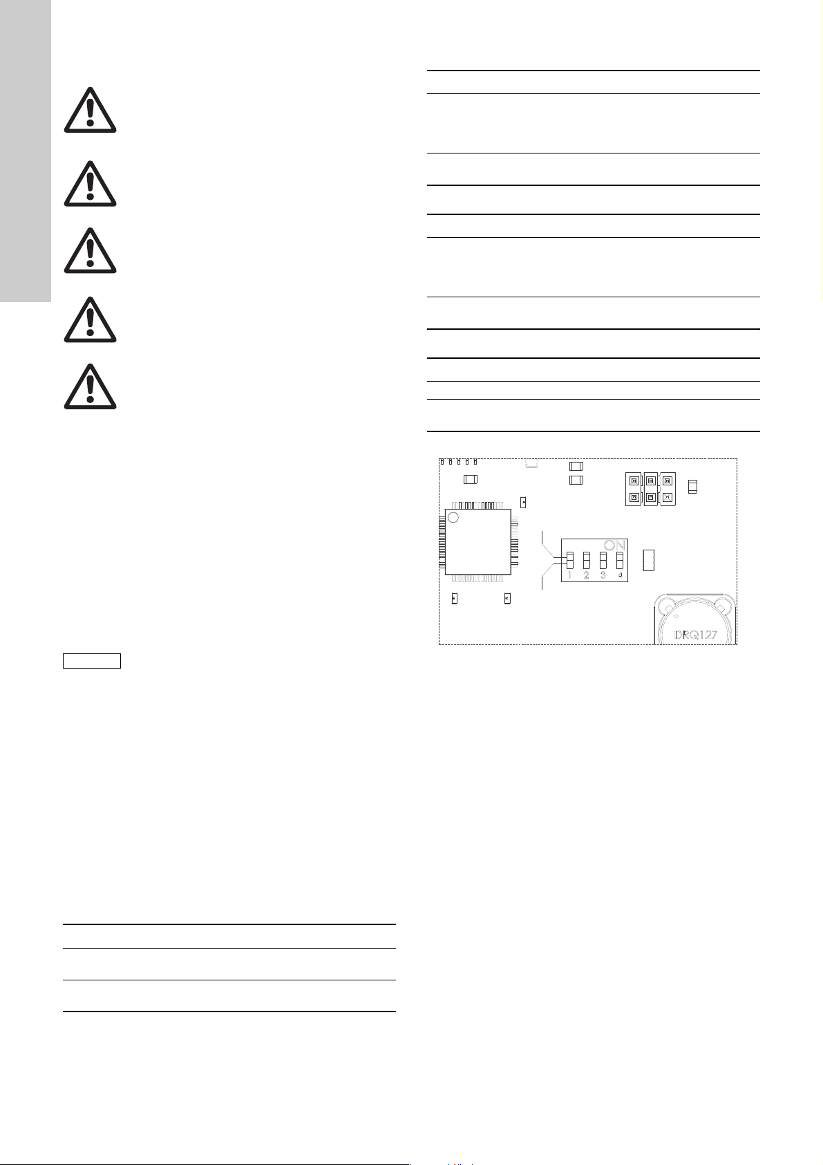
7.4 Setting of LC 220
LC 220 has a 4-contact DIP switch. See fig. 16.
To make the settings, open the cabinet cover by means of the
bayonet fastener locks. The locks on the left side have hinge
strings.
During setting, the controller must be off circuit for at
least 10 seconds to ensure the correct configuration
during startup after change of the DIP-switch setting.
The DIP switch has the following functions:
• setting of start level (switch 1). The factory setting is set to
inlet 250 mm above the floor to get the highest effective tank
volume. For floor standing toilets, the setting must be changed
to 180 mm. Starts and stops will be adjusted automatically.
• selection of automatic alarm resetting (switch 2)
• selection of service interval (switch 3)
• selection of sensor (switch 4).
The DIP-switch factory setting is shown in fig. 16.
Each individual switch (1 to 4) of the DIP switch can be set to
position OFF or ON.
When the DIP-switch setting is changed, the controller must be
switched off for at least 10 seconds!
Set the switches 1 to 4 as follows:
• Switch 1 (start level):
Pos. Description
The function for reminding that it is time for
ON
OFF
• Switch 4 (sensor resetting):
Pos. Description
ON Safe (normal position, factory default)
OFF
maintenance is activated. The yellow indication light will
be on when it is time for maintenance work.
The maintenance interval is 1 year (fixed value).
The function for reminding that it is time for
maintenance is deactivated.
Switch briefly to OFF for the sensor to adjust to the
ambient pressure. See service instructions.
Fig. 16 DIP switch
TM05 1404 2711
Pos. Description
ON
OFF
The pump starts when the level in the collecting tank
reaches 250 mm.
The pump starts when the level in the collecting tank
reaches 180 mm.
12
Page 13
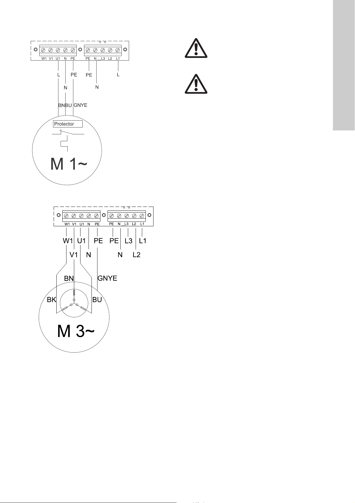
7.5 Wiring diagrams
Fig. 17 Wiring diagram for Multilift MSS, single-phase
8. Startup
Warning
Before starting any work on a pump used for
pumping liquids which could be hazardous to health,
clean and vent the pump, pit, etc., thoroughly
according to local regulations.
Warning
Before making any connections in LC 220 or working
on pump, pit, etc., make sure that the power supply
has been switched off and that it cannot be
accidentally switched on.
Prior to startup, the connection and DIP-switch setting must have
been carried out according to sections 7.3 Electrical connection
and 7.4 Setting of LC 220.
Startup must be carried out by authorised personnel.
Proceed as follows:
1. Check all connections.
2. Open the isolating valves in outlet and inlet lines.
3. Switch on the power supply.
4. Activate a sanitary appliance connected to the inflow of the
Multilift MSS and monitor the increasing water level in the tank
up to the start level. Check the starts and stops at least twice,
and then change the ON-OFF-AUTO selector switch to
TM05 1402 2711TM05 1403 2711
automatic mode.
English (GB)
Fig. 18 Wiring diagram for Multilift MSS, three-phase
13
Page 14

9. Maintenance and service
Note
Note
English (GB)
The Multilift MSS requires a minimum of maintenance.
Warning
Before carrying out maintenance and service on
lifting stations used for pumping liquids which might
be hazardous to health, make sure that the lifting
station has been thoroughly flushed with clean water
and that the outlet pipe has been drained. Rinse the
parts in water after dismantling. Make sure that the
isolating valves have been closed. The work must be
carried out in accordance with local regulations.
Warning
Before making any connections in LC 220 or working
on lifting stations, make sure that the power supply
has been switched off and that it cannot be
accidentally switched on.
According to EN 12056-4, lifting stations in single-family houses
must be checked once a year. During the check, local regulations
must be observed.
The periodic checks of the lifting station must be carried out by
authorised personnel and must comprise electrical and
mechanical maintenance.
Check the following points:
• Outlet and inlet connections
Check all connections to the lifting station for tightness and
leakages. Make sure that weight from the inlet, outlet and
venting pipes does not rest on the tank. Long pipe sections,
valves, etc. must be supported.
• Power consumption
See nameplate.
• Cable entry
Make sure that the cable entry is watertight and that the
cables are not bent sharply and/or pinched.
• Pump parts
Check that the vent hole of the pump housing is clear by
dismantling the pump from the support flange.
Do not loosen the support flange. It is screwed and
sealed to the collecting tank. Loosen the four
stainless steel clamps instead.
We recommend replacing the O-ring sealing between pump
and support flange.
Make a test run with clean water. In case of noise, vibration or
abnormal running, contact Grundfos.
• Shaft seal
Check the shaft seal, O-ring and oil. The oil chamber contains
60 ml non-poisonous oil. Used oil must be disposed of in
accordance with local regulations. This work must be carried
out by the manufacturer or an authorised service workshop.
See service instructions.
Cleaning the non-return valve (if required)
Proceed as follows:
1. Close the isolating valves in the outlet pipe and in the inlet
pipe (if fitted) or drain the outlet pipe by tightening the drain
screw on the side of the non-return valve.
See section 5.1.3 Non-return valve.
2. Clean the non-return valve via its inspection cover.
Replace the gasket of the inspection cover when
reassembling the non-return valve.
9.1 Electrical maintenance
• Check the gaskets of the LC 220 cabinet front cover and of the
cable entries.
• Check the cable connections.
• Check the controller functions.
• Check and clean the pressure tube. See section 9.2 Cleaning
the level sensor.
• If LC 220 is installed in a particularly moist environment in a
basement, we recommend checking the terminals on the PCB
in order to identify possible corrosion. In typical installations,
the contacts will work for many years and do not require any
inspection.
• Replace the 9 V battery, if fitted, in connection with annual
service.
The above list is not complete. LC 220 may be
installed in environments which require thorough and
frequent maintenance.
9.2 Cleaning the level sensor
1. Push the ON-OFF-AUTO selector switch to position OFF ( ).
See section 5.2.2 Control elements and indicator lights.
2. Loosen the screw cap by turning it counterclockwise.
See fig. 19.
3. Lift the pressure tube carefully out of the collecting tank.
Do not lift it by means of the hose.
4. Check for possible deposits on or in the pressure tube. See
section 5.1.4 Level sensor.
5. Scrape off any deposits. If necessary, remove the hose from
the controller and rinse the tube and hose with clean water at
low pressure. Make sure no water remains in the hose.
6. Refit the pressure tube by screwing the screw cap on to the
tank. Reconnect the hose to the controller.
7. Check the sensor by test running Multilift MSS.
TM05 0545 1011
Fig. 19 Removing the pressure tube
9.3 Contaminated lifting station or components
Warning
If a Multilift lifting station has been used for a liquid
which is injurious to health or toxic, it will be
classified as contaminated.
If Grundfos is requested to service the lifting station, Grundfos
must be contacted with details about the pumped liquid, etc.
before the lifting station is returned for service. Otherwise
Grundfos can refuse to accept the lifting station for service.
Lifting stations which have been in contact with the pumped liquid
must be thoroughly cleaned before they are returned to Grundfos.
Any costs of returning the lifting station are to be paid by the
customer.
However, any application for service (no matter to whom it may
be made) must include details about the pumped liquid if the
lifting station has been used for liquids which are injurious to
health or toxic.
14
Page 15

10. Fault finding
Warning
Before carrying out any work on lifting stations used for pumping liquids which might be hazardous to health, make sure that
the lifting station has been thoroughly flushed with clean water and that the outlet pipe has been drained. Rinse the parts in
water after dismantling. Make sure that the isolating valves have been closed.
The work must be carried out in accordance with local regulations.
Before making any connections in LC 220 or working on lifting stations, etc., make sure that the power supply has been
switched off and that it cannot be accidentally switched on.
Fault Cause Remedy
1. The pump does not run. a) No power supply.
2. The sensor signal is out
of range.
All pumps are started
and high-level alarm is
on.
3. The pump starts and
stops too frequently
even if there is no
inflow.
4. The pump starts
sometimes without
visible reason.
Without battery backup:
None of the indicator lights are on.
With battery backup:
See section 5.2 LC 220 controller.
b) The ON-OFF-AUTO selector switch is in
position OFF ( ). See section 5.2.2 Control
elements and indicator lights.
c) Control circuit fuses are blown. Check and eliminate the cause. Replace the control
d) The thermal switch has cut out the pump. Allow the pump to cool. After cooling, the pump will
e) Motor/supply cable is defective. Check and replace motor and cable, if necessary.
f) The power circuit board or the LED board is
defective.
g) The new DIP-switch setting does not work
correctly.
a) Not all outlet valves are open. Open all outlet valves.
b) There is a blockage in the tank or pump. Remove the blockage.
c) The pump is not vented correctly. The pump
cannot build up pressure.
d) The lifting station is undersized. Recalculate the inflow parameters and compare the
a) The level sensor is blocked. Clean the level sensor (see section 9.2 Cleaning the
b) The ventilation of the inner pump housing is
blocked and the pump cannot build up
pressure.
a) Test run 24 hours after last operation. No action necessary. It is a safety function that prevents
Switch on the power supply.
Push the ON-OFF-AUTO selector switch into position
ON ( ) or AUTO ( ).
circuit fuses.
restart automatically unless LC 220 has been set to
manual restarting (see section 7.4 Setting of LC 220).
If so, push the ON-OFF-AUTO selector switch into
position OFF ( ) for a short period.
Replace the power circuit board or LED board.
Switch off the power supply to the controller for 1 minute
and switch it on again (normal procedure). See section
7.4 Setting of LC 220.
Remove any blockage from the vent hole underneath
the pump.
result with the tank volume and pump performance. If
you need a new product, contact the nearest Grundfos
sales company.
level sensor).
Check the pump housing and remove any impurities.
the shaft seal from seizing up.
English (GB)
15
Page 16

11. Technical data
English (GB)
11.1 Lifting station
Weight:
Temperature range:
Flood conditions: Max. 2 m for 7 days
Sound pressure level
11.1.1 Collecting tank
Material: Polyethylene (PE)
11.1.2 Pump
Motor:
Mains supply: 1 x 230 V, 50 Hz
Insulation class: F (155 °C)
Impeller type: Vortex
Enclosure class: IP68
pH range: 4-10
Starts per hour: max. 60
Max. density of liquid: 1100 kg/m
Component Material
Pump housing Stainless steel 1.4301 304
Impeller Stainless steel 1.4301 304
Motor unit
complete
Pump shaft - wet
end
Motor cable Polychloroprene
O-rings NBR rubber
Oil Shell Ondina 15, non-toxic
Parts in contact with
liquid: Stainless steel 1.4401 316
Stainless steel 1.4301 304
Depending on variant.
See nameplate
0-40 °C
For short periods up to 60 °C
(max. 5 minutes per hour)
< 70 dB(A) according to
EN 12050-1 and the Machinery
Directive
3
DIN
W.-Nr.
AISI
11.2 LC 220 controller
Controller
Voltage variants, rated voltages: 1 x 230 V, 3 x 400 V
Voltage tolerances for LC 220:
Mains frequency for LC 220: 50/60 Hz
Supply system earthing: For TN systems
Controller power consumption: 7 W
Backup fuse:
Control circuit fuse:
Ambient temperature:
During operation:
In stock:
Enclosure class: IP55
Cabinet of LC 220
External dimensions:
Material:
Weight:
Outputs for alarm devices:
- 15 %/+ 10 % of rated
voltage
Depending on variant.
See nameplate
Fine-wire fuse:
100 mA / 20 mm x ∅5
0 to +40 °C (must not be
exposed to direct sunlight)
-30 to +60 °C
Height = 195 mm
Width = 250 mm
Depth = 110 mm
ABS (acrylonitrile butadiene
styrene)
Depending on variant.
See nameplate
Max. 250 VAC / max.
2 A / min. 10 mA / AC1
Multilift MSS Duty
MSS.11.1.2
MSS.11.3.2 3 x 400 V 3.2 / 16 CEE 3P+N+E, 16 A
S3 -10 %, 1 min.
Voltage
[V]
1 x 230 V
Power P1 / P2
[kW]
1.8 / 1.1
I
/ I
1/1
[A]
8 / 22.5
start
RPM
[min
2760 2
-1
Number of
]
poles
Plug type
E/F, I
-
12. Disposal
This product or parts of it must be disposed of in an
environmentally sound way:
1. Use the public or private waste collection service.
2. If this is not possible, contact the nearest Grundfos company
or service workshop.
The crossed-out wheelie bin symbol on a product
means that it must be disposed of separately from
household waste. When a product marked with this
symbol reaches its end of life, take it to a collection
point designated by the local waste disposal
authorities. The separate collection and recycling of such
products will help protect the environment and human health.
16
Page 17

Appendix 1
1. Dimensional drawings
1.1 Multilift MSS, with non-return valve
Appendix
TM05 0439 2011
17
Page 18

18
Page 19

Argentina
Bombas GRUNDFOS de Argentina S.A.
Ruta Panamericana km. 37.500 Centro
Industrial Garin
1619 Garín Pcia. de B.A.
Phone: +54-3327 414 444
Telefax: +54-3327 45 3190
Australia
GRUNDFOS Pumps Pty. Ltd.
P.O. Box 2040
Regency Park
South Australia 5942
Phone: +61-8-8461-4611
Telefax: +61-8-8340 0155
Austria
GRUNDFOS Pumpen Vertrieb Ges.m.b.H.
Grundfosstraße 2
A-5082 Grödig/Salzburg
Tel.: +43-6246-883-0
Telefax: +43-6246-883-30
Belgium
N.V. GRUNDFOS Bellux S.A.
Boomsesteenweg 81-83
B-2630 Aartselaar
Tél.: +32-3-870 7300
Télécopie: +32-3-870 7301
Belarus
Представительство ГРУНДФОС в
Минске
220125, Минск
ул. Шафарнянская, 11, оф. 56, БЦ
«Порт»
Тел.: +7 (375 17) 286 39 72/73
Факс: +7 (375 17) 286 39 71
E-mail: minsk@grundfos.com
Bosnia and Herzegovina
GRUNDFOS Sarajevo
Zmaja od Bosne 7-7A,
BH-71000 Sarajevo
Phone: +387 33 592 480
Telefax: +387 33 590 465
www.ba.grundfos.com
e-mail: grundfos@bih.net.ba
Brazil
BOMBAS GRUNDFOS DO BRASIL
Av. Humberto de Alencar Castelo Branco,
630
CEP 09850 - 300
São Bernardo do Campo - SP
Phone: +55-11 4393 5533
Telefax: +55-11 4343 5015
Bulgaria
Grundfos Bulgaria EOOD
Slatina District
Iztochna Tangenta street no. 100
BG - 1592 Sofia
Tel. +359 2 49 22 200
Fax. +359 2 49 22 201
email: bulgaria@grundfos.bg
Canada
GRUNDFOS Canada Inc.
2941 Brighton Road
Oakville, Ontario
L6H 6C9
Phone: +1-905 829 9533
Telefax: +1-905 829 9512
China
GRUNDFOS Pumps (Shanghai) Co. Ltd.
10F The Hub, No. 33 Suhong Road
Minhang District
Shanghai 201106
PRC
Phone: +86 21 612 252 22
Telefax: +86 21 612 253 33
COLOMBIA
GRUNDFOS Colombia S.A.S.
Km 1.5 vía Siberia-Cota Conj. Potrero
Chico,
Parque Empresarial Arcos de Cota Bod.
1A.
Cota, Cundinamarca
Phone: +57(1)-2913444
Telefax: +57(1)-8764586
Croatia
GRUNDFOS CROATIA d.o.o.
Buzinski prilaz 38, Buzin
HR-10010 Zagreb
Phone: +385 1 6595 400
Telefax: +385 1 6595 499
www.hr.grundfos.com
GRUNDFOS Sales Czechia and
Slovakia s.r.o.
Čajkovského 21
779 00 Olomouc
Phone: +420-585-716 111
Denmark
GRUNDFOS DK A/S
Martin Bachs Vej 3
DK-8850 Bjerringbro
Tlf.: +45-87 50 50 50
Telefax: +45-87 50 51 51
E-mail: info_GDK@grundfos.com
www.grundfos.com/DK
Estonia
GRUNDFOS Pumps Eesti OÜ
Peterburi tee 92G
11415 Tallinn
Tel: + 372 606 1690
Fax: + 372 606 1691
Finland
OY GRUNDFOS Pumput AB
Trukkikuja 1
FI-01360 Vantaa
Phone: +358-(0) 207 889 500
France
Pompes GRUNDFOS Distribution S.A.
Parc d’Activités de Chesnes
57, rue de Malacombe
F-38290 St. Quentin Fallavier (Lyon)
Tél.: +33-4 74 82 15 15
Télécopie: +33-4 74 94 10 51
Germany
GRUNDFOS GMBH
Schlüterstr. 33
40699 Erkrath
Tel.: +49-(0) 211 929 69-0
Telefax: +49-(0) 211 929 69-3799
e-mail: infoservice@grundfos.de
Service in Deutschland:
e-mail: kundendienst@grundfos.de
Greece
GRUNDFOS Hellas A.E.B.E.
20th km. Athinon-Markopoulou Av.
P.O . B o x 7 1
GR-19002 Peania
Phone: +0030-210-66 83 400
Telefax: +0030-210-66 46 273
Hong Kong
GRUNDFOS Pumps (Hong Kong) Ltd.
Unit 1, Ground floor
Siu Wai Industrial Centre
29-33 Wing Hong Street &
68 King Lam Street, Cheung Sha Wan
Kowloon
Phone: +852-27861706 / 27861741
Telefax: +852-27858664
Hungary
GRUNDFOS Hungária Kft.
Tópark u. 8
H-2045 Törökbálint,
Phone: +36-23 511 110
Telefax: +36-23 511 111
India
GRUNDFOS Pumps India Private Limited
118 Old Mahabalipuram Road
Thoraipakkam
Chennai 600 096
Phone: +91-44 2496 6800
Indonesia
PT. GRUNDFOS POMPA
Graha Intirub Lt. 2 & 3
Jln. Cililitan Besar No.454. Makasar,
Jakarta Timur
ID-Jakarta 13650
Phone: +62 21-469-51900
Telefax: +62 21-460 6910 / 460 6901
Ireland
GRUNDFOS (Ireland) Ltd.
Unit A, Merrywell Business Park
Ballymount Road Lower
Dublin 12
Phone: +353-1-4089 800
Telefax: +353-1-4089 830
Italy
GRUNDFOS Pompe Italia S.r.l.
Via Gran Sasso 4
I-20060 Truccazzano (Milano)
Tel.: +39-02-95838112
Telefax: +39-02-95309290 / 95838461
Japan
GRUNDFOS Pumps K.K.
1-2-3, Shin-Miyakoda, Kita-ku,
Hamamatsu
431-2103 Japan
Phone: +81 53 428 4760
Telefax: +81 53 428 5005
Korea
GRUNDFOS Pumps Korea Ltd.
6th Floor, Aju Building 679-5
Yeoksam-dong, Kangnam-ku, 135-916
Seoul, Korea
Phone: +82-2-5317 600
Telefax: +82-2-5633 725
Latvia
SIA GRUNDFOS Pumps Latvia
Deglava biznesa centrs
Augusta Deglava ielā 60, LV-1035, Rīga,
Tālr.: + 371 714 9640, 7 149 641
Fakss: + 371 914 9646
Lithuania
GRUNDFOS Pumps UAB
Smolensko g. 6
LT-03201 Vilnius
Tel: + 370 52 395 430
Fax: + 370 52 395 431
Malaysia
GRUNDFOS Pumps Sdn. Bhd.
7 Jalan Peguam U1/25
Glenmarie Industrial Park
40150 Shah Alam
Selangor
Phone: +60-3-5569 2922
Telefax: +60-3-5569 2866
Mexico
Bombas GRUNDFOS de México S.A. de
C.V.
Boulevard TLC No. 15
Parque Industrial Stiva Aeropuerto
Apodaca, N.L. 66600
Phone: +52-81-8144 4000
Telefax: +52-81-8144 4010
Netherlands
GRUNDFOS Netherlands
Velu we zo om 35
1326 AE Almere
Postbus 22015
1302 CA ALMERE
Tel.: +31-88-478 6336
Telefax: +31-88-478 6332
E-mail: info_gnl@grundfos.com
New Zealand
GRUNDFOS Pumps NZ Ltd.
17 Beatrice Tinsley Crescent
North Harbour Industrial Estate
Albany, Auckland
Phone: +64-9-415 3240
Telefax: +64-9-415 3250
Norway
GRUNDFOS Pumper A/S
Strømsveien 344
Postboks 235, Leirdal
N-1011 Oslo
Tlf.: +47-22 90 47 00
Telefax: +47-22 32 21 50
Poland
GRUNDFOS Pompy Sp. z o.o.
ul. Klonowa 23
Baranowo k. Poznania
PL-62-081 Przeźmierowo
Tel: (+48-61) 650 13 00
Fax: (+48-61) 650 13 50
Portugal
Bombas GRUNDFOS Portugal, S.A.
Rua Calvet de Magalhães, 241
Apartado 1079
P-2770-153 Paço de Arcos
Tel.: +351-21-440 76 00
Telefax: +351-21-440 76 90
Romania
GRUNDFOS Pompe România SRL
Bd. Biruintei, nr 103
Pantelimon county Ilfov
Phone: +40 21 200 4100
Telefax: +40 21 200 4101
E-mail: romania@grundfos.ro
Russia
ООО Грундф ос Россия
ул. Школьная, 39-41
Москва, RU-109544, Russia
Тел. (+7) 495 564-88-00 (495) 737-30-00
Факс (+7) 495 564 8811
E-mail grundfos.moscow@grundfos.com
Serbia
Grundfos Srbija d.o.o.
Omladinskih brigada 90b
11070 Novi Beograd
Phone: +381 11 2258 740
Telefax: +381 11 2281 769
www.rs.grundfos.com
Singapore
GRUNDFOS (Singapore) Pte. Ltd.
25 Jalan Tukang
Singapore 619264
Phone: +65-6681 9688
Telefax: +65-6681 9689
Slovakia
GRUNDFOS s.r.o.
Prievozská 4D
821 09 BRATISLAVA
Phona: +421 2 5020 1426
sk.grundfos.com
Slovenia
GRUNDFOS LJUBLJANA, d.o.o.
Leskoškova 9e, 1122 Ljubljana
Phone: +386 (0) 1 568 06 10
Telefax: +386 (0)1 568 06 19
E-mail: tehnika-si@grundfos.com
South Africa
GRUNDFOS (PTY) LTD
Corner Mountjoy and George Allen Roads
Wilbart Ext. 2
Bedfordview 2008
Phone: (+27) 11 579 4800
Fax: (+27) 11 455 6066
E-mail: lsmart@grundfos.com
Spain
Bombas GRUNDFOS España S.A.
Camino de la Fuentecilla, s/n
E-28110 Algete (Madrid)
Tel.: +34-91-848 8800
Telefax: +34-91-628 0465
Sweden
GRUNDFOS AB
Box 333 (Lunnagårdsgatan 6)
431 24 Mölndal
Tel.: +46 31 332 23 000
Telefax: +46 31 331 94 60
Switzerland
GRUNDFOS Pumpen AG
Bruggacherstrasse 10
CH-8117 Fällanden/ZH
Tel.: +41-44-806 8111
Telefax: +41-44-806 8115
Taiwan
GRUNDFOS Pumps (Taiwan) Ltd.
7 Floor, 219 Min-Chuan Road
Taichung, Taiwan, R.O.C.
Phone: +886-4-2305 0868
Telefax: +886-4-2305 0878
Thailand
GRUNDFOS (Thailand) Ltd.
92 Chaloem Phrakiat Rama 9 Road,
Dokmai, Pravej, Bangkok 10250
Phone: +66-2-725 8999
Telefax: +66-2-725 8998
Turkey
GRUNDFOS POMPA San. ve Tic. Ltd. Sti.
Gebze Organize Sanayi Bölgesi
Ihsan dede Caddesi,
2. yol 200. Sokak No. 204
41490 Gebze/ Kocaeli
Phone: +90 - 262-679 7979
Telefax: +90 - 262-679 7905
E-mail: satis@grundfos.com
Ukraine
Бізнес Центр Європа
Столичне шосе, 103
м. Київ, 03131, Україна
Телефон : (+38 044) 237 04 00
Факс.: (+38 044) 237 04 01
E-mail: ukraine@grundfos.com
United Arab Emirates
GRUNDFOS Gulf Distribution
P.O. Box 16768
Jebel Ali Free Zone
Dubai
Phone: +971 4 8815 166
Telefax: +971 4 8815 136
United Kingdom
GRUNDFOS Pumps Ltd.
Grovebury Road
Leighton Buzzard/Beds. LU7 4TL
Phone: +44-1525-850000
Telefax: +44-1525-850011
U.S.A.
GRUNDFOS Pumps Corporation
9300 Loiret Blvd.
Lenexa, Kansas 66219
Phone: +1-913-227-3400
Telefax: +1-913-227-3500
Uzbekistan
Grundfos Tashkent, Uzbekistan The
Representative Office of Grundfos
Kazakhstan in Uzbekistan
38a, Oybek street, Tashkent
Телефон: (+998) 71 150 3290 / 71 150
3291
Факс: (+998) 71 150 3292
Addresses Revised 14.03.2018
Grundfos companies
Page 20

98042530 1218
ECM: 1217058
www.grundfos.com
Trademarks displayed in this material, including but not limited to Grundfos, the Grundfos logo and “be think innovate” are registered trademarks owned by The Grundfos Group. All rights reserved. © 2018 Grundfos Holding A/S, all rights reserved.
 Loading...