

Page 1

GRUNDFOS INSTRUCTIONS
CRE, CRIE, CRNE, SPKE, CRKE,
MTRE, CME
Grundfos E-pumps with MLE frequency-controlled, asynchronous
motors
Installation and operating instructions
Page 2

English (US)
English (US) Installation and operating instructions
Original installation and operating instructions.
CONTENTS
1. Limited warranty
2. Symbols used in this document
3. General information
4. General description
4.1 Pumps without factory-fitted sensor
4.2 Pumps with pressure sensor
4.3 Settings
5. Mechanical installation
5.1 Motor cooling
5.2 Outdoor installation
6. Electrical connection
6.1 Single-phase pumps
6.2 Three-phase pumps, 1.5 - 10 hp
6.3 Three-phase pumps, 15-30 hp
6.4 Signal cables
6.5 E-pump electrical connections
6.6 Bus connection cable
7. Modes
7.1 Overview of modes
7.2 Operating mode
7.3 Control mode
8. Setting up the pump
8.1 Factory setting
9. Setting by means of control panel
9.1 Setting of operating mode
9.2 Setpoint setting
10. Setting by means of R100
10.1 Menu OPERATION
10.2 Menu STATUS
10.3 Menu INSTALLATION
10.4 Typical display settings for constant-pressure E-pumps
10.5 Typical display settings for analog-input E-pumps
10.6 Grundfos GO Remote
11. Setting by means of PC Tool E-products
12. Priority of settings
13. External forced-control signals
13.1 Start/stop input
13.2 Digital input
14. External setpoint signal
15. Bus signal
16. Other bus standards
17. Indicator lights and signal relay
18. Emergency operation (only 15-30 hp)
19. Insulation resistance
20. Maintenance and service
20.1 Cleaning of the motor
20.2 Relubrication of motor bearings
20.3 Replacement of motor bearings
20.4 Replacement of varistor (only 15-30 hp)
20.5 Service parts and service kits
21. Technical data - three-phase pumps, 1.5 - 10 hp
21.1 Supply voltage
21.2 Overload protection
21.3 Leakage current
21.4 Inputs/output
Page
10
10
10
10
10
11
11
11
12
12
12
14
15
16
23
24
25
26
26
26
26
27
27
28
28
28
30
31
31
31
31
31
31
31
31
31
31
31
31
22. Technical data - three-phase pumps, 15-30 hp
22.1 Supply voltage
22.2 Overload protection
22.3 Leakage current
2
3
3
3
3
3
3
3
3
3
4
4
4
6
9
9
22.4 Inputs/output
22.5 Other technical data
23. Disposal
1. Limited warranty
Products manufactured by GRUNDFOS PUMPS CORPORATION
(Grundfos) are warranted to the original user only to be free of
defects in material and workmanship for a period of 24 months
from date of installation, but not more than 30 months from date
of manufacture. Grundfos' liability under this warranty shall be
limited to repairing or replacing at Grundfos' option, without
charge, F.O.B. Grundfos' factory or authorized service station,
any product of Grundfos' manufacture. Grundfos will not be liable
for any costs of removal, installation, transportation, or any other
charges which may arise in connection with a warranty claim.
Products which are sold but not manufactured by Grundfos are
subject to the warranty provided by the manufacturer of said
products and not by Grundfos' warranty. Grundfos will not be
liable for damage or wear to products caused by abnormal
operating conditions, accident, abuse, misuse, unauthorized
alteration or repair, or if the product was not installed in
accordance with Grundfos' printed installation and operating
instructions.
To obtain service under this warranty, the defective product must
be returned to the distributor or dealer of Grun dfos' products from
which it was purchased together with proof of purchase and
installation date, failure date, and supporting installation data.
Unless otherwise provided, the distributor or dealer will contact
Grundfos or an authorized service station for instructions. Any
defective product to be returned to Grundfos or a service station
must be sent freight prepaid; documentation supporting the
warranty claim and/or a Return Material Authorization must be
included if so instructed.
GRUNDFOS WILL NOT BE LIABLE FOR ANY INCIDENTAL OR
CONSEQUENTIAL DAMAGES, LOSSES, OR EXPENSES
ARISING FROM INSTALLATION, USE, OR ANY OTHER
CAUSES. THERE ARE NO EXPRESS OR IMPLIED
WARRANTIES, INCLUDING MERCHANTABILITY OR FITNESS
FOR A PARTICULAR PURPOSE, WHICH EXTEND BEYOND
THOSE WARRANTIES DESCRIBED OR REFERRED TO
ABOVE.
Some jurisdictions do not allow the exclusion or limitation of
incidental or consequential damages and some jurisdictions do
not allow limit actions on how long implied warranties may last.
Therefore, the above limitations or exclusions may not apply to
you. This warranty gives you specific legal rights and you may
also have other rights which vary from jurisdiction to jurisdiction.
Warnin g
Prior to installation, read these installation and
operating instructions. Installation and operation
must comply with local regulations and accepted
codes of good practice.
32
32
32
32
32
33
33
2
Page 3

2. Symbols used in this document
Caution
Note
Note
Note
Note
Warnin g
If these safety instructions are not observed, it
may result in personal injury!
Warnin g
The surface of the product may be so hot that
it may cause burns or personal injury.
If these safety instructions are not observed,
it may result in malfunction or damage to the
equipment.
4.3 Settings
The description of settings apply both to pumps without factoryfitted sensor and to pumps with a factory-fitted pressure sensor.
Setpoint
The desired setpoint can be set in three different ways:
• directly on the pump control panel
• via an input for external setpoint signal
• by means of Grundfos wireless remote control R100.
Other settings
All other settings can only be made by means of the R100.
Important parameters such as actual value of control parameter,
power consumption, etc. can be read via the R100.
If special or customized settings are required, use Grundfos PC
Tool E-products. Contact your local Grundfos company for more
information.
English (US)
Notes or instructions that make the job easier
and ensure safe operation.
3. General information
These installation and operating instructions are a supplement to
installation and operating instructions for the corresponding
standard pumps CR, CRI, CRN, CRK, SPK, MTR, CHI and CM.
For instructions not mentioned specifically here, please see
installation and operating instructions for the standard pump.
4. General description
Grundfos E-pumps have standard motors with integrated
frequency converter. The pumps are for single-phase or threephase power supply connection.
4.1 Pumps without factory-fitted sensor
The pumps have a built-in PI controller and can be set up for an
external sensor enabling control of the following parameters:
• pressure
• differential pressure
• temperature
• differential temperature
•flow rate
• liquid level in a tank.
From factory, the pumps have been set to control mode
uncontrolled. The PI controller can be activated by means of
R100.
4.2 Pumps with pressure sensor
The pumps have a built-in PI controller and are set up with a
pressure sensor enabling control of the pump discharge
pressure.
The pumps are set to control mode controlled. The pumps are
typically used to hold a constant pressure in variable-demand
systems.
5. Mechanical installation
The pump must be secured to a solid foundation by means of
bolts through the holes in the flange or baseplate.
In order to retain the UL/cUL approval, follow the
additional installation procedures on page 35.
5.1 Motor cooling
To ensure sufficient cooling of motor and electronics, observe the
following requirements:
• Make sure that sufficient cooling air is available.
• Keep the temperature of the cooling air below 104 °F (40 °C).
• Keep cooling fins and fan blades clean.
5.2 Outdoor installation
When installed outdoors, the pump must be provided with a
suitable cover to avoid condensation on the electronic
components. See fig. 1.
TM00 8622 0101 - TM02 8514 0304
Fig. 1 Examples of covers
Remove the drain plug pointing downwards in order to avoid
moisture and water build-up inside the motor.
Vertically mounted pumps are IP55 after removal of the drain
plug. Horizontally mounted pumps change enclosure class to
IP54.
3
Page 4
English (US)
N
PE
L
N
L
PE
ELCB
ELCB
L1
L2
L3
L2
L1
L3
PE
ELCB
6. Electrical connection
For description of how to connect E-pumps electrically, see the
following pages:
6.1 Single-phase pumps, page 4
6.2 Three-phase pumps, 1.5 - 10 hp, page 4
6.3 Three-phase pumps, 15-30 hp, page 6.
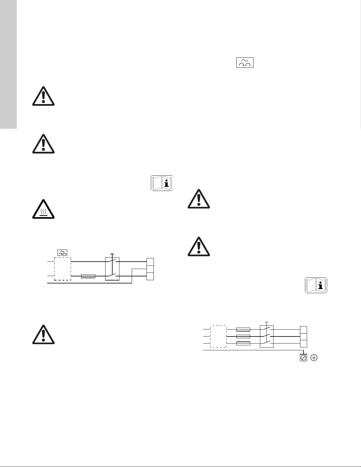
6.1.4 Additional protection
If the pump is connected to an electric installation where an
ground leakage circuit breaker (ELCB) is used as additional
protection, the circuit breaker must be of a type marked with the
following symbol:
6.1 Single-phase pumps
Warnin g
The user or the installer is responsible for the
installation of correct grounding and protection
according to current national and local
standards. All operations must be carried out by
qualified personnel.
Warnin g
Never make any connections in the pump
terminal box unless all electric supply circuits
have been switched off for at least 5 minutes.
Note for instance that the signal relay may be
connected to an external supply which is still
connected when the power supply is
disconnected.
The above warning is indicated on the motor terminal
box by this yellow label:
Warnin g
The surface of the terminal box may be above
158 °F (70 °C) when the pump is operating.
6.1.1 Preparation
Before connecting the E-pump to the power supply, take the
issues illustrated in the figure below into consideration.
The total leakage current of all the electrical equipment in the
installation must be taken into account.
The leakage current of the motor in normal operation can be seen
in section 22.3 Leakage current on page 32.
During start and at asymmetrical supply systems, the leakage
current can be higher than normal and may cause the ELCB to
trip.
6.1.5 Motor protection
The pump requires no external motor protection. The motor
incorporates thermal protection against slow overloading and
blocking (IEC 34-11, TP 211).
6.1.6 Protection against voltage transients
The pump is protected against voltage transients by built-in
varistors between phase-neutral and phase-ground.
6.2 Three-phase pumps, 1.5 - 10 hp
Warnin g
The user or the installer is responsible for the
installation of correct grounding and protection
according to current national and local
standards. All operations must be carried out by
qualified personnel.
Warnin g
Never make any connections in the pump
terminal box unless all electric supply circuits
have been switched off for at least 5 minutes.
Note for instance th at th e sign al rel ay may be
connected to an external supply which is still
connected when the power supply is
disconnected.
Fig. 2 Power supply-connected pump with power switch,
backup fuse, additional protection and protective
grounding
6.1.2 Protection against electric shock - indirect contact
Warnin g
The pump must be grounded and protected
against indirect contact in accordance with
national regulations.
Protective ground leads must always have a yellow/green (PE) o r
yellow/green/blue (PEN) color marking.
6.1.3 Backup fuses
For recommended fuse sizes, see section 22.1 Supply voltage on
page 32.
4
The above warning is indicated on the motor terminal
TM02 0792 0101
box by this yellow label:
6.2.1 Preparation
Before connecting the E-pump to the power supply, take the
issues illustrated in the figure below into consideration.
Fig. 3 Power supply-connected pump with power switch,
backup fuses, additional protection and protective
grounding
TM00 9270 4696
Page 5

6.2.2 Protection against electric shock - indirect contact
ELCB
Caution
Note
Note
L1
L2
L3
L1
L2
L3
Warnin g
The pump must be grounded in accordance with
national regulations.
As the leakage current of 5-10 hp (4 - 7.5 kW)
motors is > 3.5 mA, take extra precautions when
grounding these motors.
EN 50178 and BS 7671 specify the following precautions when
leakage current > 3.5 mA:
• The pump must be stationary and installed permanently.
• The pump must be permanently connected to the power
supply.
• The grounding connection must be carried out as duplicate
leads.
Protective ground leads must always have a yellow/green (PE) o r
yellow/green/blue (PEN) color marking.
6.2.3 Backup fuses
For recommended fuse sizes, see section 21.1 Supply voltage on
page 32.
6.2.4 Additional protection
If the pump is connected to an electric installation where an
ground leakage circuit breaker (ELCB) is used as additional
protection, the circuit breaker must be of a type marked with the
following symbols:
English (US)
TM03 8600 2007
Fig. 4 Power connection
Cable glands
Cable glands comply with EN 50626.
• 2 x M16 cable gland
• 1 x M20 cable gland
• 2 x M16 knock-out cable entries.
This circuit breaker is type B.
The total leakage current of all the electrical equipment in the
installation must be taken into account.
The leakage current of the motor in normal operation can be seen
in section 21.3 Leakage current on page 31.
During start and at asymmetrical supply systems, the leakage
current can be higher than normal and may cause the ELCB to
trip.
6.2.5 Motor protection
The pump requires no external motor protection. The motor
incorporates thermal protection against slow overloading and
blocking (IEC 34-11, TP 211).
6.2.6 Protection against voltage transients
The pump is protected against voltage transients by built-in
varistors between the phases and between phases and ground.
6.2.7 Supply voltage and power supply
3 x 460-480 V - 10 %/+ 10 %, 50/60 Hz, PE.
3 x 208-230 V - 10 %/+ 10 %, 50/60 Hz, PE.
The supply voltage and frequency are marked on the pump
nameplate. Make sure that the pump is suitable for the power
supply of the installation site.
The wires in the terminal box must be as short as possible.
Excepted from this is the protective ground lead which must be so
long that it is the last one to be disconnected in case the cable is
inadvertently pulled out of the cable entry.
Warnin g
If the supply cable is damaged, it must be
replaced by qualified personnel.
Grid types
Three-phase E-pumps can be connected to all grid types.
Warnin g
Do not connect three-phase E-pumps to a power
supply with a voltage between phase and ground
of more than 440 V.
6.2.8 Start/stop of pump
The number of starts and stops via the power
supply must not exceed 4 times per hour.
When the pump is switched on via the power supply, it will start
after approx. 5 seconds.
If a higher number of starts and stops is desired, use the input for
external start/stop when starting/stopping the pump.
When the pump is switched on via an external on/off switch, it will
start immediately.
Automatic restart
If a pump set up for automatic restart is stopped
due to a fault, it will restart automatically when
the fault has disappeared.
However, automatic restart only applies to fault types set up to
automatic restart. These faults could typically be one of these
faults:
• temporary overload
• fault in the power supply.
5
Page 6

English (US)
Note
Note
6: GND (frame)
5: +10 V
4: Setpoint input
3: GND (frame)
2: Start/stop
Group 1
Group 2
Group 3
13: GND (frame)
12: Analog output
11: Digital input 4
10: Digital input 3
1: Digital input 2
9: GND (frame)
8: +24 V
7: Sensor input
B: RS-485B
Y: Screen
A: RS-485A
L1
L2
L3
L2
L1
L3
PE
ELCB
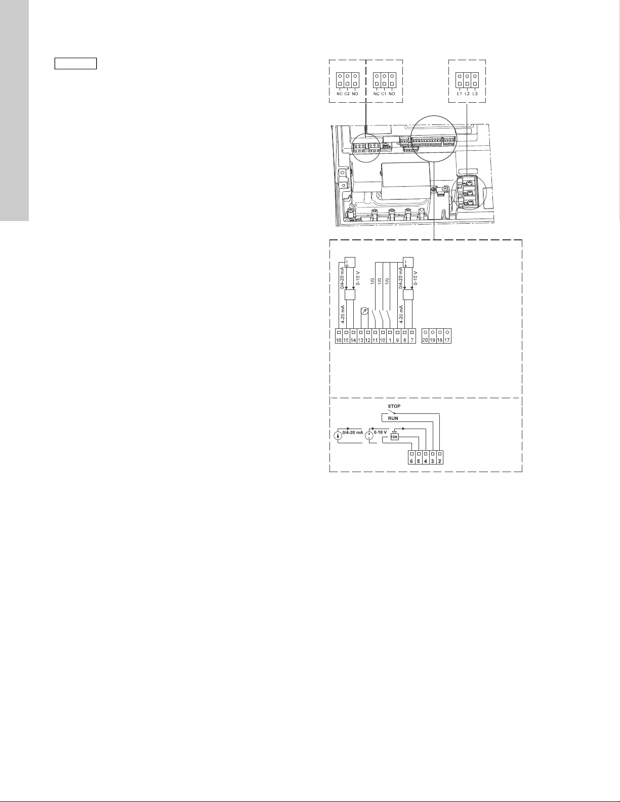
6.2.9 Connections
6.3 Three-phase pumps, 15-30 hp
If no external on/off switch is connected,
connect terminals 2 and 3 using a short wire.
As a precaution, the wires to be connected to the following
connection groups must be separated from each other by
reinforced insulation in their entire lengths:
Group 1: Inputs
• start/stop terminals 2 and 3
• digital input terminals 1 and 9
• setpoint input terminals 4, 5 and 6
• sensor input terminals 7 and 8
• GENIbus terminals B, Y and A
All inputs (group 1) are internally separated from the powerconducting parts by reinforced insulation and galvanically
separated from other circuits.
All control terminals are supplied with protective extra-low voltage
(PELV), thus ensuring protection against electric shock.
Group 2: Output (relay signal, terminals NC, C, NO)
The output (group 2) is galvanically separated from other circuits.
Therefore, the supply voltage or protective extra-low voltage can
be connected to the output as desired.
6.2.10 Three-phase pumps, 1.5 - 10 hp
Group 3: Power supply (terminals L1, L2, L3)
Warnin g
The user or the installer is responsible for the
installation of correct grounding and protection
according to current national and local
standards. All operations must be carried out by
qualified personnel.
Warnin g
Never make any connections in the pump
terminal box unless all electric supply circuits
have been switched off for at least 5 minutes.
Note for instance th at th e sign al rel ay may be
connected to an external supply which is still
connected when the power supply is
disconnected.
Warnin g
The surface of the terminal box may be above
158 °F (70 °C) when the pump is operating.
6.3.1 Preparation
Before connecting the E-pump to the power supply, take the
issues illustrated in the figure below into consideration.
Fig. 5 Connection terminals
A galvanic separation must fulfill the requirements for reinforced
insulation including creepage distances and clearances specified
in EN 60335.
6
TM00 9270 4696
Fig. 6 Power supply-connected pump with power switch,
backup fuses, additional protection and protective
grounding
6.3.2 Protection against electric shock - indirect contact
Warnin g
The pump must be grounded in accordance with
national regulations.
As the leakage current of 15-30 hp motors is
> 10 mA, take extra precautions when grounding
these motors.
EN 61800-5-1 specifies that the pump must be stationary and
installed permanently when the leakage current is > 10 mA.
One of the following requirements must be fulfilled:
• A single protective ground lead (7 AWG m i n i m u m copper)
TM05 2985 0812
TM04 3021 3508
Fig. 7 Connection of a single protective ground lead using
one of the leads of a 4-core power cable
(7 AWG minimum)
Page 7

• Two protective ground leads of the same cross-sectional area
ELCB
Caution
Torques, terminals L1-L3:
Min. torque: 1.6 ft-lbs
Max. torque: 1.8 ft-lbs
as the power supply leads, with one lead connected to an
additional ground terminal in the terminal box.
Fig. 8 Connection of two protective ground leads using two of
the leads of a 5-core power supply cable
Protective ground leads must always have a yellow/green (PE) o r
yellow/green/blue (PEN) color marking.
6.3.3 Backup fuses
For recommended fuse sizes, see section 22.1 Supply voltage on
page 32.
6.3.4 Additional protection
If the pump is connected to an electric installation where an
ground leakage circuit breaker (ELCB) is used as additional
protection, the circuit breaker must be of a type marked with the
following symbols:
This circuit breaker is type B.
The total leakage current of all the electrical equipment in the
installation must be taken into account.
The leakage current of the motor in normal operation can be seen
in section 22.3 Leakage current.
During start and at asymmetrical supply systems, the leakage
current can be higher than normal and may cause the ELCB to
trip.
6.3.5 Motor protection
The pump requires no external motor protection. The motor
incorporates thermal protection against slow overloading and
blocking (IEC 34-11, TP 211).
6.3.6 Protection against voltage transients
The pump is protected against voltage transients in accordance
with EN 61800-3 and is capable of withstanding a VDE 0160
pulse.
The pump has a replaceable varistor which is part of the transie nt
protection.
Over time this varistor will be worn and need to be replaced.
When the time for replacement has come, R100 and PC Tool
E-products will indicate this as a warning. See section
20. Maintenance and service on page 31.
6.3.7 Supply voltage
3 x 460-480 V - 10 %/+ 10 %, 50/60 Hz, PE.
The supply voltage and frequency are marked on the pump
nameplate. Make sure that the motor is suitable for the power
supply of the installation site.
The wires in the terminal box must be as short as possible.
Excepted from this is the protective ground lead which must be so
long that it is the last one to be disconnected in case the cable is
inadvertently pulled out of the cable entry.
TM03 8606 2007
Fig. 9 Power connection
Cable glands
Cable glands comply with EN 50626.
• 1 x M40 cable gland
• 1 x M20 cable gland
• 2 x M16 cable gland
• 2 x M16 knock-out cable entries.
Warnin g
If the supply cable is damaged, it must be
replaced by qualified personnel.
Grid types
Three-phase E-pumps can be connected to all grid types.
Warnin g
Do not connect three-phase E-pumps to a power
supply with a voltage between phase and ground
of more than 440 V.
6.3.8 Start/stop of pump
The number of starts and stops via the power
supply must not exceed 4 times per hour.
When the pump is switched on via the power supply, it will start
after approx. 5 seconds.
If a higher number of starts and stops is desired, use the input for
external start/stop when starting/stopping the pump.
When the pump is switched on via an external on/off switch, it will
start immediately.
English (US)
TM03 8605 2007 - TM04 3048 3508
7
Page 8
English (US)
Note
Note
6: GND (frame)
5: +10 V
4: Setpoint input
3: GND (frame)
2: Start/stop
Group 2
Group 3
20: PT 100 B
19: PT 100 B
18: PT 100 A
17: PT 100 A
16: GND (frame)
15: +24 V
14: Sensor input 2
13: GND
12: Analog output
11: Digital input 4
10: Digital input 3
1: Digital input 2
9: GND (frame)
8: +24 V
7: Sensor input
B: RS-485B
Y: Screen
A: RS-485A
Group 1
6.3.9 Connections
If no external on/off switch is connected, connect
terminals 2 and 3 using a short wire.
As a precaution, the wires to be connected to the following
connection groups must be separated from each other by
reinforced insulation in their entire lengths:
Group 1: Inputs
• start/stop terminals 2 and 3
• digital input terminals 1 and 9
• setpoint input terminals 4, 5 and 6
• sensor input terminals 7 and 8
• GENIbus terminals B, Y and A
All inputs (group 1) are internally separated from the powerconducting parts by reinforced insulation and galvanically
separated from other circuits.
All control terminals are supplied with protective extra-low voltage
(PELV), thus ensuring protection against electric shock.
Group 2: Output (relay signal, terminals NC, C, NO)
The output (group 2) is galvanically separated from other circuits.
Therefore, the supply voltage or protective extra-low voltage can
be connected to the output as desired.
Group 3: Power supply (terminals L1, L2, L3)
TM05 2986 0812
Fig. 10 Connection terminals
A galvanic separation must fulfill the requirements for reinforced
insulation including creepage distances and clearances specified
in EN 61800-5-1.
8
Page 9

6.4 Signal cables
Dry-running sensor
Set to automatic resetting
Connection terminals on E-pump:
2 (Start/Stop) and 3 (GND)
3
2
1 x 200-240 VAC
or
1 X 80-130 VAC
Brown
Black
Blue
White
Jumper cable
• Use screened cables with a conductor cross-section of min.
28 AWG and max. 16 AWG for external on/off switch, digital
input, setpoint and sensor signals.
• Connect the screens of the cables to frame at both ends with
good frame connection. The screens must be as close as
possible to the terminals. See fig. 11.
Fig. 11 Stripped cable with screen and wire connection
• Always tighten screws for frame connections whether a cable
is fitted or not.
• Make the wires in the pum p ter m inal box as short as possible.
6.5.2 Connection of E-pump to LiqTec®
6.5 E-pump electrical connections
6.5.1 Connection of E-pump to Danfoss pressure sensor MBS3000
The blue wire of the pressure sensor is connected to the #7
terminal of the E-pump. The brown wire of the pressure sensor is
connected to the #8 terminal of the E-pump.
See section 6.4 Signal cables on page 9 for additional details.
TM02 1325 0901
Fig. 12 Danfoss pressure sensor
English (US)
TM05 1533 2911
TM03 0437 5104
Fig. 13 Connection of E-pump to LiqTec
9
Page 10

English (US)
A
Y
B
A
Y
B
1
2
3
1
2
3
Pump
A
Y
B
A
Y
B
1
2
1
2
Pump
Q
H
Max.
Min.
H
Q
6.6 Bus connection cable
6.6.1 New installations
For the bus connection, use a screened 3-core cable with a
conductor cross-section of 28-16 AWG.
• If the pump is connected to a unit with a cable clamp which is
identical to the one on the pump, connect the screen to this
cable clamp.
• If the unit has no cable clamp as shown in fig. 14, leave the
screen unconnected at this end.
7.2 Operating mode
When the operating mode is set to Normal, the control mode can
be set to controlled or uncontrolled. See section 7.3Control mode
on page 10.
The other operating modes that can be selected are S t op, Min. or
Max.
• Stop: the pump has been stopped
• Min.: the pump is operating at its minimum speed
• Max.: the pump is operating at its maximum speed.
Figure 16 is a schematic illustration of min. and max. curves.
Fig. 14 Connection with screened 3-core cable
6.6.2 Replacing an existing pump
• If a screened 2-core cable is used in the existing installation,
connect it as shown in fig. 15.
Fig. 15 Connection with screened 2-core cable
• If a screened 3-core cable is used in the existing installation,
follow the instructions in section 6.6.1 New installations on
page 10.
7. Modes
Grundfos E-pumps are set and controlled according to operating
and control modes.
7.1 Overview of modes
TM02 8841 0904TM02 8842 0904
TM00 5547 0995TM00 7746 1304
Fig. 16 Min. and max. curves
The max. curve can for instance be used in connection with the
venting procedure during installation.
The min. curve can be used in periods in which a minimum flow is
required.
If the power supply to the pump is disconnected, the mode sett ing
will be stored.
The remote control R100 offers additional possibilities of setting
and status displays. See section 10. Setting by means of R100 on
page 12.
7.3 Control mode
7.3.1 Pumps without factory-fitted sensor
The pumps are factory-set to control mode uncontrolled.
In control mode uncontrolled, the pump will operate according to
the constant curve set, fig. 17.
Operating modes Normal Stop Min. Max.
Control modes Uncontrolled Controlled
Fig. 17 Pump in control mode uncontrolled (constant curve)
Constant
curve
1) For this control mode the pump is equipped with a pressure
Constant
pressure
1)
sensor. The pump may also be equipped with a temperature
sensor in which case the description would be constant
temperature in control mode controlled.
10
Page 11

7.3.2 Pumps with pressure sensor
Q
H
set
H
Q
H
UncontrolledControlled
Light fields Buttons
Indicator lights
Buttons
Indicator lights
Light fields
The pump can be set to one of two control modes, i.e. controlled
and uncontrolled, fig. 18.
In control mode controlled, the pump will adjust its performance,
i.e. pump discharge pressure, to the desired setpoint for the
control parameter.
In control mode uncontrolled, the pump will operate according to
the constant curve set.
Fig. 18 Pump in control mode controlled (constant pressure)
or uncontrolled (constant curve)
8. Setting up the pump
8.1 Factory setting
Pumps without factory-fitted sensor
The pumps have been factory-set to control mode uncontrolled.
The setpoint value corresponds to 100 % of the maximum pump
performance (see data sheet for the pump).
Pumps with pressure sensor
The pumps have been factory-set to control mode controlled.
The setpoint value corresponds to 50 % of the sensor measuring
range (see sensor nameplate).
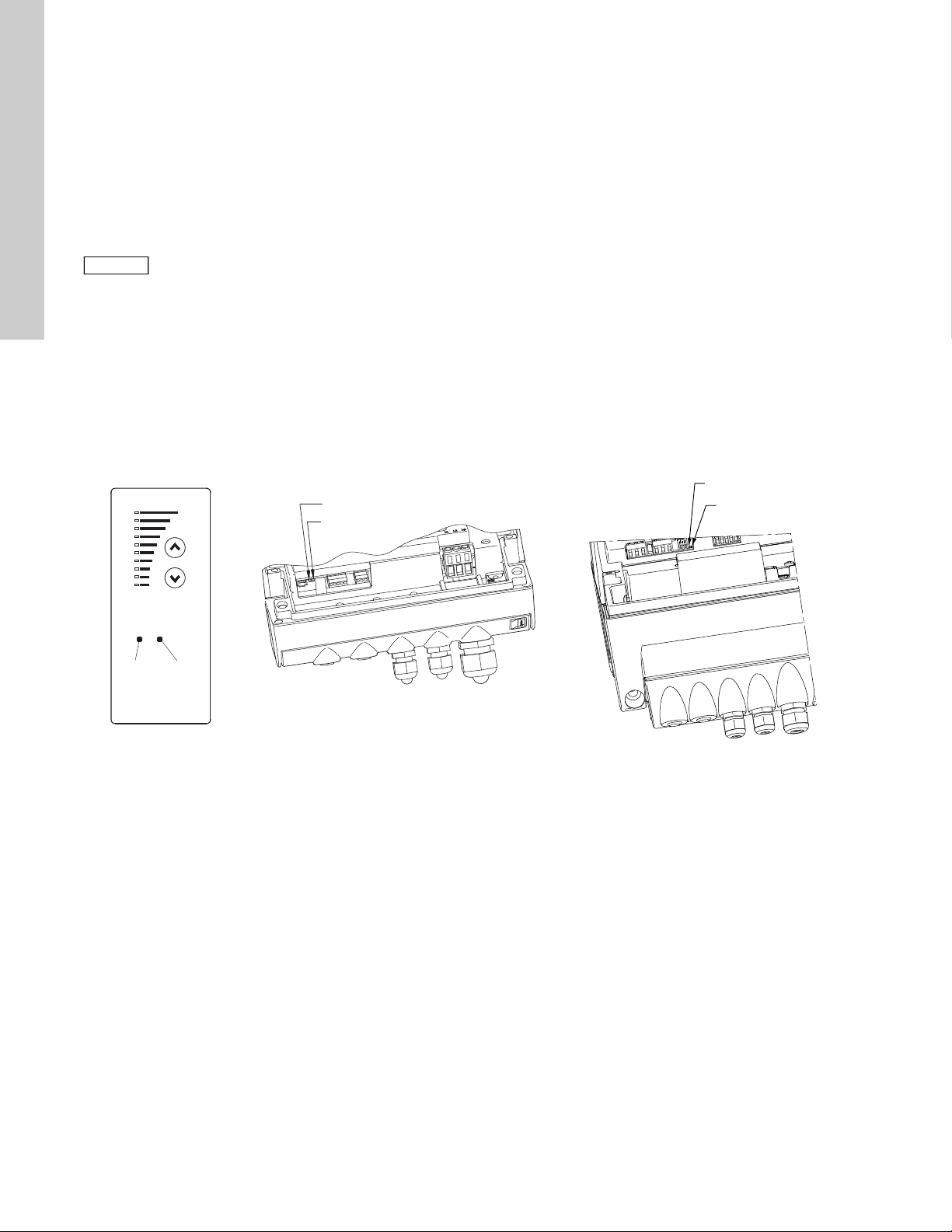
9. Setting by means of control panel
The pump control panel, see fig. 19 or 20, incorporates the
following buttons and indicator lights:
• Buttons, and , for setpoint setting.
• Light fields, yellow, for indication of setpoint.
• Indicator lights, green (operation) and red (fault).
TM00 7668 0404
Fig. 19 Control panel, single-phase pumps, 0.5 - 1.5 hp
English (US)
TM00 7600 0304TM02 8513 0304
Fig. 20 Control panel, three-phase pumps, 1-30 hp
11
Page 12

English (US)
H
Q
H
Q
0
6
3
[bar]
H
Q
9.1 Setting of operating mode
Settings available:
•Normal
•Stop
•Min.
•Max.
Start/stop of pump
Start the pump by continuously pressing until the desired
setpoint is indicated. This is operating mode Normal.
Stop the pump by continuously pressing until none of the light
fields are activated and the green indicator light flashes.
Setting to Min.
Press
(bottom light field flashes). When the bottom light field is on,
press for 3 seconds until the light field starts flashing.
To return to uncontrolled or controlled operation, press
continuously until the desired setpoint is indicated.
continuously to change to the min. curve of the pump
TM00 7743 0904TM00 7746 1304TM02 0936 0501
Fig. 23 Setpoint set to 3 bar, pressure control
9.2.2 Pump in control mode uncontrolled Example
In control mode uncontrolled, the pump performance is set within
the range from min. to max. curve. See fig. 24.
TM00 7346 1304TM00 7345 1304
Fig. 21 Min. curve duty
Setting to Max.
Press continuously to change to the max. curve of the pump
(top light field flashes). When the top light field is on, press for
3 seconds until the light field starts flashing.
To return to uncontrolled or controlled operation, press
continuously until the desired setpoint is indicated.
Fig. 22 Max. curve duty
9.2 Setpoint setting
Set the desired setpoint by pressing the button or .
The light fields on the control panel will indicate the setpoint set.
See examples in sections 9.2.1 on page 12 and 9.2.2 on page 12.
9.2.1 Pump in control mode controlled (pressure control)
Example
Figure 23 shows that the light fields 5 and 6 are activated,
indicating a desired setpoint of 3 bar. The setting range is equal
to the sensor measuring range (see sensor nameplate).
Fig. 24 Pump performance setting, control mode uncontrolled
10. Setting by means of R100
The pump is designed for wireless communication with
Grundfos remote control R100.
Fig. 25 R100 communicating with the pump via infra-red light
During communication, the R100 must be pointed at the control
panel. When the R100 communicates with the pump, the red
indicator light will flash rapidly. Keep pointing the R100 at the
control panel until the red LED diode stops flashing.
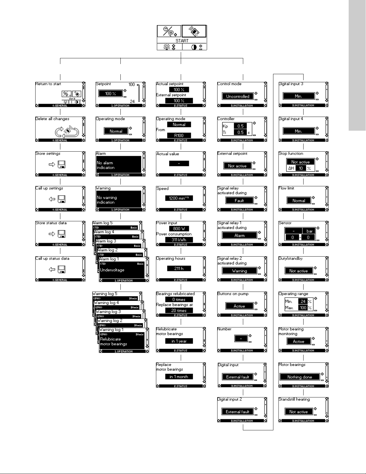
The R100 offers setting and status displays for the pump.
The displays are divided into four parallel menus (see fig. 34):
0. GENERAL (see operating instructions for the R100)
1. OPERATION
2. STATUS
3. INSTALLATION
The figure above each individual display in fig. 34 refers to the
section in which the display is described.
12
Page 13
0. GENERAL 1. OPERATION 2. STATUS 3. INSTALLATION
10.1.1 10.2.1 10.3.1 10.3.7
10.1.2 10.2.2 10.3.2 10.3.7
10.1.3 10.2.3 10.3.3 10.3.8
10.1.3 (1) 10.2.4 10.3.4 (3) 10.3.9 (1)
10.1.4 10.2.5 10.3.4 - 1 (2) 10.3.10
English (US)
10.2.6 10.3.4 - 2 (2) 10.3.11 (1)
10.1.4 (1) 10.2.7 (2) 10.3.5 10.3.12
10.2.8 (2) 10.3.6 10.3.13 (1)
10.2.9 (1) 10.3.7 10.3.14 (1)
(1) This display only appears for three-phase pumps, 1.5 - 30 hp.
(2) This display only appears for three-phase pumps, 15 - 30 hp.
(3) This display only appears for three-phase pumps, 1.5 - 10 hp.
10.3.7 10.3.15 (1)
Fig. 26 Menu overview
13
Page 14

English (US)
Note
Note
Displays in general
In the following explanation of the functions, one or two displays
are shown.
One display
Pumps without or with factory-fitted sensor have the same
function.
Two displays
Pumps without or with factory-fitted pressure sensor have
different functions and factory settings.
10.1 Menu OPERATION
The first display in this menu is this:
10.1.1 Setpoint
Without sensor
(uncontrolled)
Setpoint set
Actual setpoint
Actual value
Set the setpoint in %.
In control mode uncontrolled, the setpoint is set in % of the
maximum performance. The setting range will lie between the
min. and max. curves.
In control mode controlled, the setting range is equal to the
sensor measuring range.
If the pump is connected to an external setpoint signal, the value
in this display will be the maximum value of the external setpoint
signal. See section 14. External setpoint signal on page 27.
Setpoint and external signal
The setpoint cannot be set if the pump is controlled via external
signals (Stop, Min. curve or Max. curve). R100 will give this
warning: External control!
Check if the pump is stopped via terminals 2-3 (open circuit) or
set to min. or max. via terminals 1-3 (closed circuit).
See Fig. 35 Menu overview on page 24.
Setpoint and bus communication
The setpoint cannot be set either if the pump is co ntrolled from a n
external control system via bus communication. R100 will give
this warning: Bus control!
To override bus communication, disconnect the bus connection.
See Fig. 35 Menu overview on page 24.
10.1.2 Operating mode
Set one of the following operating modes:
• Normal (duty)
•Stop
•Min.
•Max.
With pressure sensor
(controlled)
Setpoint set
Actual setpoint
Actual value
Set the desired pressure in
bar.
The operating modes can be set without changing the setpoint
setting.
10.1.3 Fault indications
In E-pumps, faults may result in two types of indication: alarm or
warning.
An "alarm" fault will activate an alarm indication in R100 and
cause the pump to change operating mode, typically to stop.
However, for some faults resulting in alarm, the pump is set to
continue operating even if there is an alarm.
A "warning" fault will activate a warning indication in R100, but
the pump will not change operating or control mode.
The indication, Warning, only applies to threephase pumps.
Alarm
In case of alarm, the cause will appear in this display.
Possible causes:
• No alarm indication
• Too high motor temperature
• Undervoltage
• Mains voltage asymmetr y (15-30 hp)
•Overvoltage
• Too many restarts (after faults)
• Overload
• Underload
• Sensor signal outside signal range
• Setpoint signal outside signal range
• External fault
• Duty/standby, Communication fault
• Dry running
• Other fault.
If the pump has been set up to manual restar t, an alarm indication
can be reset in this display if the cause of the fault has
disappeared.
Warning (only three-phase pumps)
In case of warning, the cause will appear in this display.
Possible causes:
• No warning indication.
• Sensor signal outside signal range.
• Relubricate motor bearings, see section 20.2 on page 31.
• Replace motor bearings, see section 20.3 on page 31.
• Replace varistor, see section 20.4 on page 31.
A warning indication will disappear automatically once the fault
has been remedied.
14
Page 15

10.1.4 Fault log
For both fault types, alarm and warning, the R100 has a log
function.
Alarm log
In case of "alarm" faults, the last five alarm indications will appear
in the alarm log. "Alarm log 1" shows the latest fault, "Alarm log 2 "
shows the latest fault but one, etc.
The example above gives this information:
• the alarm indication Undervoltage
• the fault code (73)
• the number of minutes the pump has been connected to the
power supply after the fault occurred, 8 min.
Warning log
In case of "warning" faults, the last five warning indications will
appear in the warning log. "Warning log 1" show s the la test fa ult,
"Warning log 2" shows the latest fault but one, etc.
The example above gives this information:
• the warning indication Relubricate motor bearings
• the fault code (240)
• the number of minutes the pump has been connected to the
power supply since the fault occurred, 30 min.
10.2 Menu STATUS
The displays appearing in this menu are status displays only. It is
not possible to change or set values.
The displayed values are the values that applied when the last
communication between the pump and the R100 took place. If a
status value is to be updated, point the R100 at the control panel
and press "OK". If a parameter, e.g. speed, should be called up
continuously, press "OK" const antly during the period in wh ich the
parameter in question should be monitored.
The tolerance of the displayed value is stated under e ach display.
The tolerances are stated as a guide in % of the maximu m va lues
of the parameters.
10.2.1 Actual setpoint
Without sensor
(uncontrolled)
With pressure sensor
(controlled)
10.2.2 Operating mode
This display shows the actual operating mode (Normal (duty),
Stop, Min., or Max.). Furthermore, it shows where this operating
mode was selected (R100, Pump, Bus, External or Stop func.).
For further details about the stop function (Stop func.), see
section 10.3.8 Stop function on page 19.
10.2.3 Actual value Without sensor
(uncontrolled)
This display shows the value actually measured by a connected
sensor.
If no sensor is connected to the pump, "-" will appear in the
display.
10.2.4 Speed
Tolerance: ± 5 %
The actual pump speed will appear in this display.
10.2.5 Power input and power consumption
Tolerance: ± 10 %
This display shows the actual pump input power from the power
supply. The power is displayed in W or kW.
The pump power consumption can also be read from this display.
The value of power consumption is an accumulated value
calculated from the pump’s birth and it cannot be reset.
10.2.6 Operating hours
With pressure sensor
(controlled)
English (US)
Tolerance: ± 2 %. Tolerance: ± 2 %.
This display shows the actual setpoint and the external se tpoint in
% of the range from minimum value to the setpoint set. See
section 14. External setpoint signal on page 27.
Tolerance: ± 2 %
The value of operating hours is an accumulated value and cannot
be reset.
15
Page 16

English (US)
Note
Note
10.2.7 Lubrication status of motor bearings (only 15-30 hp)
10.3 Menu INSTALLATION
10.3.1 Control mode
This display shows how many times the motor bearings have
been relubricated and when to replace the motor bearings.
When the motor bearings have been relubricated, confirm this
action in the INSTALLATION menu.
See section 10.3.14 Confirming relubrication/replacement of
motor bearings (only three-phase pumps) on page 22. When
relubrication is confirmed, the figure in the above display will be
increased by one.
10.2.8 Time till relubrication of motor bearings
This display shows when to relubricate the motor bearings. The
controller monitors the operating pattern of the pump and
calculates the period between bearing relubrications. If the
operating pattern changes, the calculated time till relubrication
may change as well.
The displayable values are these:
• in 2 years
• in 1 year
• in 6 months
• in 3 months
• in 1 month
• in 1 week
•Now!
10.2.9 Time till replacement of motor bearings
When the motor bearings have been relubricated a prescribed
number of times stored in the controller, the display in section
10.2.8 Time till relubrication of motor bearings on page 16 will be
replaced by the display below.
Without sensor
(uncontrolled)
Select one of the following
control modes (see fig. 18):
• Controlled
• Uncontrolled.
With pressure sensor
(controlled)
Select one of the following
control modes (see fig. 18):
• Controlled
• Uncontrolled.
If the pump is connected to a bus, the control
mode cannot be selected via the R100. See
section 15. Bus signal.
10.3.2 Controller
E-pumps have a factory default setting of gain (K
time (T
). However, if the factory setting is not the optimum
i
setting, the gain and the integral time can be changed in the
) and integral
p
display below.
• The gain (K
) can be set within the range from 0.1 to 20.
p
• The integral time (Ti) can be set within the range from 0.1 to
3600 s. If 3600 s is selected, the controller will function as a P
controller.
• Furthermore, it is possible to set the controller to inverse
control, meaning that if the setpoint is increased, the speed
will be reduced. In the case of inverse control, the gain (Kp)
must be set within the range from -0.1 to -20.
This display shows when to replace the motor bearings. The
controller monitors the operating pattern of the pump and
calculates the period between bearing replacements.
The displayable values are these:
• in 2 years
• in 1 year
• in 6 months
• in 3 months
• in 1 month
• in 1 week
•Now!
16
Page 17

The table below shows the suggested controller settings: How to set the PI controller
p
p
L1 [ft]
p
Q
t
L L2 [ft]
t
L2 [ft]
t
L2 [ft]
For most applications, the factory setting of the controller
constants K
However, in some applications an adjustment of the controller
and Ti will ensure optimum pump operation.
p
may be needed.
Proceed as follows:
1. Increase the gain (K
) until the motor becomes uns table.
p
System/application
Heating
systems
K
p
Cooling
system
T
i
Instability can be seen by observing if the measured value
0.5 0.5
starts to fluctuate. Furthermore, instability is audible as the
motor starts hunting up and down.
Some systems, such as temperature controls, are slowreacting, meaning that it may be several minutes before the
motor becomes unstable.
0.5
L
< 16.4 ft: 0.5
1)
L > 16.4 ft: 3
L > 32.8 ft: 5
2. Set the gain (K
unstable. This is the correct setting of the gain.
3. Reduce the integral time (T
unstable.
4. Set the integral time (T
motor unstable. This is the correct setting of the integral time.
) to half of the value which made the motor
p
) to twice the value which made the
i
General rules of thumb:
0.5 0.5
• If the controller is too slow-reacting, increase K
• If the controller is hunting or unstable, dampen the system by
reducing K
or increasing Ti.
p
10.3.3 External setpoint
0.5 0.5
) until the motor becomes
i
.
p
English (US)
0.5 -0.5 10 + 1.52L
0.5 10 + 1.52L
0.5 -0.5 30 + 1.52L
+2.5 100
Heating systems are systems in which an increase in pump
performance will result in a rise in temperature at the
sensor.
Cooling systems are systems in which an increase in pump
performance will result in a drop in temperature at the
sensor.
(L1) Distance in [ft] between pump and sensor
(L2) Distance in [ft] between heat exchanger and sensor
The input for external setpoint signal can be set to dif fere nt signal
types.
Select one of the following types:
•0-10 V
•0-20 mA
•4-20 mA
• Not active.
If Not active is selected, the setpoint set by means of the R100 or
on the control panel will apply.
If one of the signal types is selected, the actual setpoint is
influenced by the signal connected to the external setpoint input.
See section 14. External setpoint signal on page 27.
17
Page 18

English (US)
Note
Note
10.3.4 Signal relay
Pumps of 1.5 - 10 hp have one signal relay. The factory setting of
the relay will be Fault.
Pumps of 15-30 hp have two signal relays. Signal relay 1 is
factory set to Alarm and signal relay 2 to Warning.
In one of the displays below, select in which one of three or six
operating situations the signal relay should be activated.
1.5 - 10 hp
• Ready
• Fault
• Operation
• Pump running (only three-phase pumps, 1.5 - 10 hp)
• Warning (only three-phase pumps, 1-10 hp).
15-30 hp 15-30 hp
10.3.5 Buttons on pump
The operating buttons and on the control panel can be set
to these values:
•Active
• Not active.
When set to Not active (locked), the buttons do not function. Set
the buttons to Not active if the pump should be controlled via an
external control system.
10.3.6 Pump number
A number between 1 and 64 can be allocated to the pump. In the
case of bus communication, a number must be allocated to each
pump.
10.3.7 Digital inputs
• Ready
•Alarm
• Operation
• Pump running
• Warning
• Relubricate.
Fault and Alarm cover faults resulting in Alarm.
Warning covers faults resulting in Warning.
Relubricate covers only that one individual event.
For distinction between alarm and warning, see
section 10.1.3 Fault indications on page 14 .
For further information, see section 17. Indicator lights and signal
relay on page 28.
• Ready
•Alarm
• Operation
• Pump running
• Warning
• Relubricate.
The digital inputs of the pump can be set to different functions.
Select one of the following functions:
• Min. (min. curve)
• Max. (max. curve)
• External fault
• Flow switch
• Dry running (from external sensor) (only three-phase pumps).
The selected function is activated by closing the contact between
terminals 1 and 9, 1 and 10 or 1 and 11.
See also section 13.2 Digital input on page 27.
Min.:
When the input is activated, the pump will operate according to
the min. curve.
Max.:
When the input is activated, the pump will operate according to
the max. curve.
External fault:
When the input is activated, a timer will be started. If the input is
activated for more than 5 seconds, the pump will be stopped and
a fault will be indicated. If the input is deactivated for more than 5
seconds, the fault condition will cease and the pump can only be
restarted manually by resetting the fault indication.
Flow switch:
When this function is selected, the pump will be stopped when a
connected flow switch detects low flow.
It is only possible to use this function if the pump is connected to
a pressure sensor.
If the input is activated for more than 5 seconds, the stop function
incorporated in the pump will take over. See section 10. 3.8 Stop
function on page 19.
18
Page 19

Dry running
Stop pressure
ΔH
Start pressure
H
Q
Caution
Pressure sensor
Diaphragm tank
Non-return
valve
Pump
Diaphragm tank
Pressure sensor
Pump Non-return valve
When this function is selected, lack of inlet pressure or water
shortage can be detected. This requires the use of an accessory,
such as these:
®
• a Grundfos Liqtec
dry-running sensor
• a pressure switch installed on the suction side of a pump
• a float switch installed on the suction side of a pump.
When lack of inlet pressure or water shortage (Dry running) is
detected, the pump will be stopped. The pump cannot restart as
long as the input is activated.
10.3.8 Stop function
The stop function can be set to these values:
•Active
• Not active.
When the stop function is active, the pump will be stopped at very
low flows. The controller will stop the pump to protect the pump
as follows:
• avoid unnecessary heating of the pumped liquid
• reduce wear of the shaft seals
• reduce noise from operation.
Three-phase pumps
1. If the flow is higher than the low-flow limit, the pump will return
to continuous operation at constant pressure.
2. If the flow is still lower than the low-flow limit, the pump will
continue in start/stop operation. It will continue in start/stop
operation until the flow is higher than the low-flow limit; when
the flow is higher than the low-flow limit, the pump will return
to continuous operation.
2. Flow switch
When the digital input is activated for more than 5 seconds
because there is low flow, the speed will be increased until the
stop pressure (actual setpoint + 0.5 x ΔH) is reached, and the
pump will stop. When the pressure has fallen to start pressure,
the pump will start again. If there is still no flow, the pump will
quickly reach stop pressure and stop. If there is flow, the pump
will continue operating according to the setpoint.
Operating conditions for the stop function
It is only possible to use the stop function if the system
incorporates a pressure sensor, a non-return valve and a
diaphragm tank.
The non-return valve must always be installed
before the pressure sensor. See fig. 28 and
fig. 29.
English (US)
Fig. 27 Difference between start and stop pressures (H)
ΔH is factory-set to 10 % of actual setpoint.
ΔH can be set within the range from 5 % to 30 % of actual
setpoint.
Low flow can be detected in two different ways:
1. A built-in "low-flow detection function" which functions if the
digital input is not set up for flow switch.
2. A flow switch connected to the digital input.
1. Low-flow detection function
The pump will check the flow regularly by reducing the speed for
a short time. If there is no or only a small change in pressure, this
means that there is low flow. The sp eed will be increased until the
stop pressure (actual setpoint + 0.5 x ΔH) is reached and the
pump will stop. When the pressure has fallen to the start pressure
(actual setpoint - 0.5 x ΔH), the pump will restart.
When restarting, the pumps will react differently according to
pump type:
TM03 8582 1907TM03 8583 1907
Fig. 28 Position of the non-return valve and pressure sensor in
system with suction lift operation
TM00 7744 1896
Fig. 29 Position of the non-return valve and pressure sensor in
system with positive inlet pressure
19
Page 20

English (US)
Note
Note
ΔH
Low
High
Normal
Diaphragm tank
The stop function requires a diaphragm tank of a certain minimum
size. The tank must be installed immediately after the pump and
the precharge pressure must be 0.7 x actual setpoint.
Recommended diaphragm tank size:
Rated flow of
pump
3
[gpm (m
h)]
0-26
(0 - 5.9)
27-105
(6.1 - 23.8)
106-176
(24.2 - 40)
177-308
(40.2 - 70.0)
309-440
(70.2 - 99.9)
441-750
(100-170)
CRE pump
1s, 1, 3 2 (7.6)
5, 10, 15 4.4 (16.7)
20, 32 14 (53.0)
45 34 (128.7)
64, 90 62 (234.7)
120, 150 86 (325.5)
Typical diaphragm
tank size
[gal (liter)]
If a diaphragm tank of the above size is installed in the system,
the factory setting of ΔH is the correct setting.
If the tank installed is too small, the pump will start and stop too
often. This can be remedied by increasing ΔH.
10.3.9 Flow limit for the stop function
Flow limit for the stop function only works if the
system is not set up for flow switch.
In order to set at which flow rate the system is to go from
continuous operation at constant pressure to start/stop operation,
select among these four values of which three are preconfigured
flow limits:
•Low
•Normal
•High
•Custom.
The default setting of the pump is Normal, representing approx.
10 % of the rated flow rate of the pump.
If a lower flow limit than normal is desired or the tank size is
smaller than recommended, select Low.
If a higher flow than normal is wanted or a large tank is used, set
the limit to High.
The value Custom can be seen in R100 but it can only be set by
means of the PC Tool E-products. Custom is for customized setup and optimizing to the process.
Fig. 30 Three preconfigured flow limits, Low, Normal and High
10.3.10 Sensor Without sensor
(uncontrolled)
With pressure sensor
(controlled)
The setting of the sensor is only relevant in the case of controlled
operation.
Select among the following values:
• Sensor output signal
0-10 V
0-20 mA
4-20 mA,
• Unit of measurement of sensor:
bar, mbar, m, kPa, psi, ft, m³/h, m³/s, l/s, gpm, °C, °F, %,
• Sensor measuring range.
10.3.11 Duty/standby
The duty/standby function applies to two pumps connected in
parallel and controlled via GENIbus.
The duty/standby function can be set to these values:
•Active
• Not active.
When the function is set to Active, the following applies:
• Only one pump is running at a time.
• The stopped pump (standby) will automatically be cut in if the
running pump (duty) has a fault. A fault will be indicated.
• Changeover between the duty pump and the standby pump
will take place every 24 hours.
Activate the duty/standby function as follows:
1. Install and prime the two pumps according to the installation
and operating instructions supplied with the pumps.
2. Check that the power supply is connected to the first pump
according to the installation and operating instructions.
3. Use Grundfos R100 to set the duty/standby to Not active in
the installation menu.
TM03 9060 3307
20
Page 21

4. Use Grundfos R100 to set the Operating mode to Stop in the
PE
L3
L2
L1
Cable gland
Plug
H
100 %
Max. curve
12 %
Min. curve
Op
e
rat
i
n
g
ra
ng
e
operation menu.
5. Use Grundfos R100 to set the other displays as required for
the pump application (such as setpoint).
6. Disconnect the power supply to both pumps.
7. Installation of the AYB cable (91125604):
a. Remove the plug from ea ch M LE term inal bo x with a flat
head screw driver. See fig. 31.
b. Screw a new cable gland into each MLE terminal box with a
crescent wrench. See fig. 31.
c. Loosen the new cable gland caps and push the cable ends
through the cable glands and into MLE motors.
d. Remove the AYB connector plug from the first MLE motor.
See fig. 32.
e. Connect the black wire to the A terminal of the AYB
connector plug.
f. Connect the orange wire to the Y terminal of the AYB
connector plug.
g. Connect the red wire to the B terminal of the AYB connector
plug.
h. Reconnect the AYB connector plug to the first MLE motor.
i. Tighten the cable gland cap to secure the cable. See fig. 31.
j. Repeat steps d to i for the second MLE motor.
8. Connect the power supply to the two pumps according to the
installation and operation instructions.
9. Use Grundfos R100 to check that the Operating mode is set to
Normal in the operation menu of the second pump.
10.Use Grundfos R100 to set the other displays as required for
the pump application (such as Setpoint).
11.Use Grundfos R100 to set the duty/standby to Active in the
installation menu of the second pump. Please note the second
pump will search for the first pump and automatically set the
duty/standby to Active in the installation menu.
12.The second pump will operate for the first 24 hours. The two
pumps will then alternate operation every 24 hours.
English (US)
TM05 2985 0812TM00 7747 1896
Fig. 32 AYB connector plug
10.3.12 Operating range
How to set the operating range:
• Set the min. curve within the range from max. curve to 12 % of
maximum performance. The pump is factory-set to 24 % of
maximum performance.
• Set the max. curve within the range from maximum
performance (100 %) to min. curve.
The area between the min. and max. curves is the operating
range.
TM05 1626 3311
Fig. 31 Removing the plug and connecting cable gland to the
terminal box
Fig. 33 Setting of the min. and max. curves in % of maximum
performance
21
Page 22

English (US)
Note
Note
Note
Note
10.3.13 Motor bearing monitoring (only three-phase pumps)
The motor bearing monitoring function can be set to these values:
•Active
• Not active.
When the function is set to Active, a counter in the controller will
start counting the mileage of the bearings. See section
10.2.7 Lubrication status of motor bearings (only 15-30 hp) on
page 16.
The counter will continue counting even if the
function is switched to Not active, but a warning
will not be given when it is time for relubrication.
When the function is switched to Active again,
the accumulated mileage will again be used to
calculate the relubrication time.
10.3.14 Confirming relubrication/replacement of motor bearings (only three-phase pumps)
This function can be set to these values:
• Relubricated (only 15-30 hp)
•Replaced
• Nothing done.
When the bearing monitoring function is Active, the controller will
give a warning indication when the motor bearings are due to be
relubricated or replaced. See section 10.1.3 Fault indications on
page 14.
When the motor bearings have been relubricated or replaced,
confirm this action in the above display by pressing OK.
Relubricated cannot be selected for a period of
time after confirming relubrication.
10.3.15 Standstill heating (only three-phase pumps)
The standstill heating function can be set to these values:
•Active
• Not active.
When the function is set to Active, an AC voltage will be applied
to the motor windings. The applied voltage will ensure that
sufficient heat is generated to avoid condensation in the motor.
22
Page 23

10.4 Typical display settings for constant-pressure E-pumps
1. OPERATION 2. STATUS 3. INSTALLATION
10.1.1 10.2.1 10.3.1 10.3.7
10.1.2 10.2.2 10.3.2 10.3.7
10.1.3 10.2.3 10.3.3 10.3.8
10.1.3 (1) 10.2.4 10.3.4 - 1 (2) 10.3.9 (1)
English (US)
10.2.5 10.3.4 - 2 (2) 10.3.10
10.2.6 10.3.5 10.3.11 (1)
10.2.7 (2) 10.3.6 10.3.12
10.2.8 (2) 10.3.7 10.3.13 (1)
(1) This display only appears for three-phase pumps, 1.5 - 30 hp.
(2) This display only appears for three-phase pumps, 15 - 30 hp.
(3) This display only appears for three-phase pumps, 1.5 - 10 hp.
10.3.14 (1)
10.3.15 (1)
Fig. 34 Menu overview
23
Page 24

English (US)
10.5 Typical display settings for analog-input E-pumps
1. OPERATION 2. STATUS 3. INSTALLATION
10.1.1 10.2.1 10.3.1 10.3.7
10.1.2 10.2.2 10.3.2 10.3.7
10.1.3 10.2.3 10.3.3 10.3.8
10.1.3 (1) 10.2.4 10.3.4 - 1 (2) 10.3.9 (1)
10.2.5 10.3.4 - 2 (2) 10.3.10
10.2.6 10.3.5 10.3.11 (1)
10.2.7 (2) 10.3.6 10.3.12
10.2.8 (2) 10.3.7 10.3.13 (1)
(1) This display only appears for three-phase pumps, 1.5 - 30 hp.
(2) This display only appears for three-phase pumps, 15 - 30 hp.
(3) This display only appears for three-phase pumps, 1.5 - 10 hp.
10.3.14 (1)
10.3.15 (1)
Fig. 35 Menu overview
24
Page 25

10.6 Grundfos GO Remote
+
1
2
3
+
+
1
2
3
5
7
9
10
13
15 16 17 18
14
12
11
8
6
4
Dashboard
The motor is designed for wireless radio or infrared
communication with Grundfos GO Remote.
Grundfos GO Remote enables setting of functions and gives
access to status overviews, technical product information and
actual operating parameters.
English (US)
Grundfos GO Remote offers three different mobile interfaces
(MI). See fig. 36.
TM05 5609 3912
Fig. 37 Example of dashboard
Pos. Description Action
This text appears when Grundfos
GO Remote app has connected
to an MI 201, MI 202 or MI 301.
If the hardware is not connected,
it will not be possible to
communicate with a Grundfos
product.
Fig. 36 Grundfos GO Remote communicating with the motor
via radio or infrared light
Connection
1
TM05 5383 3612
indicator
2 Back button Returns to the previous display.
Pos. Description
3
Product
information
Grundfos MI 201:
1
Consists of an Apple iPod touch 4G and a Grundfos
cover.
Grundfos MI 202:
2
Add-on module which can be used in conjunction
with Apple iPod touch 4, iPhone 4G or later.
Grundfos MI 301:
Separate module enabling radio or infrared
communication. The module can be used in
3
conjunction with an Android or iOS-based
Smartphone with Bluetooth connection.
10.6.1 Communication
When Grundfos GO Remote communicates with the pump, the
indicator light in the middle of the Grundfos Eye will flash green.
Communication must be established using one of these
communication types:
• radio communication
• infrared communication.
Radio communication
Radio communication can take place at distances up to 30
meters. It is necessary to enable communication by pressing
4 Product name
Alarms and
5
warnings
6 Grundfos Eye
Primary status
7
value
Secondary status
8
value
9 Control source
10 Control mode
Actual setpoint
11
value
12 Operating mode Shows the operating mode.
13 Show menu Gives access to other menus.
14 Stop Stops the product.
Tool bar
or on the pump control panel.
Infrared communication
15 Help
When communicating via infrared light, Grundfos GO Remote
must be pointed at the pump control panel.
10.6.2 Navigation
Navigation can be done from the dashboard. See fig. 37.
16 Documentation
17 Report
18 Update
Provides technical information
about the product.
Name of the product
communicating with Grundfos GO
Remote.
Shows alarms and warnings.
Shows the operating condition of
the product.
Shows the primary status value.
Shows the secondary status
value.
Shows by which interface the
product is controlled.
Shows the control mode of the
product.
Shows the actual setpoint value.
The help function describes the
menus making it easy for the user
to change settings, etc.
Gives access to installation and
operating instructions and quick
guides.
Enables the creation of userdefined reports.
Enables update of Grundfos GO
Remote app.
25
Page 26

English (US)
Note
Note
Q
H
Q
H
11. Setting by means of PC Tool E-products
Special setup requirements differing from the settings available
via the R100 require the use of Grundfos PC Tool E-products.
This again requires the assistance of a Grundfos service
technician or engineer. Contact your local Grundfos company for
more information.
12. Priority of settings
The priority of settings depends on two factors:
1. control source
2. settings.
1. Control source
Control panel
R100
External signals
(external setpoint signal, digital inputs, etc.).
Communication from another control system via
bus
2. Settings
• Operating mode Stop
• Operating mode Max. (Max. curve)
• Operating mode Min. (Min. curve)
• Setpoint setting.
An E-pump can be controlled by different control sources at the
same time, and each of these sources can be set differently.
Consequently, it is necessary to set an order of priority of the
control sources and the settings.
If two or more settings are activated at the same
time, the pump will operate according to the
function with the highest priority.
Priority of settings without bus communication
Priority of settings with bus communication
Priority
Example: If the E-pump is operating according to a setpoint set
via bus communication, the control panel or R100 can set the
E-pump to operating mode Stop or Max., and the external signal
can only set the E-pump to operating mode Stop.
Control panel
or R100
1 Stop
2 Max.
3 Stop Stop
4 Max.
5 Min.
6 Setpoint setting
External
signals
Bus
communication
13. External forced-control signals
The pump has inputs for external signals for these forced-control
functions:
• Start/stop of pump
• Digital function.
13.1 Start/stop input
Functional diagram: Start/stop input:
Start/stop (term inals 2 and 3)
Normal duty
Stop
Priority Control panel or R100 External signals
1 Stop
2 Max.
3 Stop
4 Max.
5 Min. Min.
6 Setpoint setting Setpoint setting
Example: If the E-pump has been set to operating mode Max.
(Max. frequency) via an external signal, such as digital input, the
control panel or R100 can only set th e E -pump to ope rating mode
Stop.
26
Page 27

13.2 Digital input
Q
H
Q
H
Q
H
Q
H
5 s
delay
Q
H
5 s
5 s
delay
Q
H
Setpoint
External setpoint
Actual setpoint
0 10 V
0 20 mA
4 20 mA
Actual setpoint
Sensor
max
Setpoint set by means of
control panel, R100 or PC Tool
E-products
Sensor
min
External setpoint signal
Actual
setpoint
0 10 V
0 20 mA
4 20 mA
Actual setpoint
Max
curve
Setpoint set by means of
control panel, R100 or PC Tool
E-products
Min
curve
External setpoint signal
Actual
setpoint
By means of the R100, one of the following functions can be
selected for the digital input:
• Normal duty
•Min. curve
•Max. curve
• External fault
• Flow switch
• Dry running.
Functional diagram: Input for digital function
Digital function
(terminals 1 and 9) (terminals 9 and 10) (terminals 9 and 11)
Normal duty
English (US)
TM02 8988 1304
Fig. 39 Relation between the actual setpoint and the external
setpoint signal in control mode controlled
Min. curve
Max. curve
External fault
Flow switch
Dry running
14. External setpoint signal
The setpoint can be remote-set by connecting an analogue signal
transmitter to the input for the setpoint signal (terminal 4).
Example: At a sensor
and an external setpoint of 80 % (an 8V analog signal to Terminal
value of 0 psi, a setpoint set of 50 psi
min
4 if using an analog signal of 0-10 V), the actual setpoint will be
as follows:
Actual
setpoint
= (se tpoi nt - se nsor
min
) x %
external setpoint
+ sensor
min
= (50 - 0) x 80 % + 0
=40 psi
In control mode uncontrolled, the setpoint can be set externally
within the range from the min. curve to the setpoint set on the
pump or by means of the R100. Typically the setpoint is set to
100 % when the control mode is uncontrolled
(see section 10.5 Typical display settings for analog-input E-
pumps on page 24).
Select the actual external signal, 0-10 V, 0-20 mA, 4-20 mA, via
the R100. See section 10.3.3 External setpoint on page 17.
If control mode uncontrolled is selected by means of the R100,
the pump can be controlled by any controller.
In control mode controlled, the setpoint can be set externally
within the range from the lower value of the sensor measuring
range to the setpoint set on the pump or by means of the R100.
Fig. 38 Actual setpoint as a product (multiplied value) of
setpoint and external setpoint
TM02 8988 1304
TM03 8601 2007
Fig. 40 Relation between the actual setpoint and the external
setpoint signal in control mode uncontrolled
27
Page 28
English (US)
Note
Note
Green Red
Green
Red
Green
Red
15. Bus signal
The pump supports serial communication via an RS-485 input.
The communication is carried out according to Grundfos bus
protocol, GENIbus protocol, and enables connection to a building
management system or another external control system.
Operating parameters, such as setpoint, operating mode, et c. can
be remote-set via the bus signal. At the same time, the pump can
provide status information about important parameters, such as
actual value of control parameter, input power, fault indications,
etc.
Contact Grundfos for further details.
If a bus signal is used, the number of settings
available via the R100 will be reduced.
16. Other bus standards
Grundfos offers various bus solutions with communication
according to other standards.
Contact Grundfos for further details.
17. Indicator lights and signal relay
The operating condition of the pump is indicated by the green an d
red indicator lights fitted on the pump control panel and inside the
terminal box. See fig. 41.
Besides, the pump incorporates an output for a potential-free
signal via an internal relay.
For signal relay output values, see section 10.3.4 Signal relay on
page 18.
28
TM02 8513 0304
Fig. 41 Position of indicator lights
TM02 9036 4404
TM03 9063 3307
Page 29

The functions of the two indicator lights and the signal relay are as shown in the following table:
NCNOCNCNOCNCNOCNCNO
C
NCNO
C
C
NO NCCNO NCCNO NC
NCNO
C
C
NO NCCNO NC
NCNO
C
NCNOCNCNO
C
C
NO NC
NCNO
C
C
NO NC
NCNOCNCNOCNCNO
C
C
NO NCCNO NCCNO NCCNO NC
C
NO NC
NCNO
C
C
NO NC
NCNO
C
Indicator lights Signal relay activated during:
Fault
(red)
Operation
(green)
Fault/Alarm,
Warning
and
Operating Ready
Pump
running
Description
Relubricate
Off Off The power supply has been switched off.
Off
Off
Permanently
on
Permanently
on
The pump is operating.
The pump is stopped by the stop
function.
Off Flashing The pump has been set to stop.
The pump has stopped because of a
Fault/Alarm or is running with a Warning
or Relubricate indication.
If the pump was stopped, restarting will
Permanently
on
Off
be attempted (it may be nece ssar y to
restart the pump by resetting the Fault
indication).
If the cause is "external fault", the pump
must be restarted manually by resetting
the Fault indication.
The pump is operating, but it has or has
had a Fault/Alarm allowing the pump to
continue operation or it is operating with
a Warning or Relubricate indication.
If the cause is "sensor signal outside
signal range", the pump will continue
Permanently onPermanently
on
operating according to the 70 % curve
and the fault indication cannot be reset
until the signal is inside the signal range.
If the cause is "setpoint signal outside
signal range", the pump will continue
operating according to the min. curve and
the fault indication cannot be reset until
the signal is inside the signal range.
English (US)
Permanently
on
Flashing
The pump has been set to stop, but it has
been stopped because of a Fault.
Resetting of fault indication
A fault indication can be reset in one of the following ways:
• Briefly press the button or on the pump. This will not
change the setting of the pump.
A fault indication cannot be reset by means of or if the
buttons have been locked.
• Switch off the power supply until the indicator lights are off.
• Switch the external start/stop input off and then on again.
• Use the R100. See section 10.1.3 Fault indications.
When the R100 communicates with the pump, the red indicator
light will flash rapidly.
29
Page 30

English (US)
Caution
18. Emergency operation (only 15-30 hp)
Warnin g
Never make any connections in the pump
terminal box unless all electric supply circuits
have been switched off for at least 5 minutes.
Note for instance that the signal relay may be
connected to an external supply which is still
connected when the power supply is
disconnected.
If the pump is stopped and you cannot start the pump
immediately after normal remedies, the reason could be a faulty
frequency converter. If this is the case it is possible to maintain
emergency operation of the pump.
Before change over to emergency operation we recommend you
to:
• check that the power supply is OK
• check that control signals are working (start/stop signals)
• check that all alarms are reset
• make a resistance test on the motor windings (disconnect the
motor leads from the terminal box).
If the pump remains stopped it is possible that the frequency
converter is faulty.
To establish emergency operation proceed as follows:
1. Disconnect the three power supply leads, L1, L2, L3, from the
terminal box, but leave the protective ground lead(s) in
position on the PE terminal(s).
3. Connect the leads as shown in fig. 42.
TM04 0018 4807TM03 9121 3407TM03 9122 3407
Fig. 42 How to switch an E-pump from normal operation to
emergency operation
Use the screws from the power supply terminals and the nuts
from the motor terminals.
2. Disconnect the motor supply leads, U/W1, V/U1, W/V1, from
the terminal box.
4. Insulate the three leads from each other by means of
insulating tape or the like.
TM03 8607 2007TM03 9120 3407
TM03 9123 3407
Warnin g
Do not bypass the frequency converter by
connecting the power supply leads to the U, V
and W terminals.
This may cause hazardous situations for
personnel as the high voltage potential of the
power supply may be transferred to touchable
components in the terminal box.
Check the direction of rotation when starting up
after switching to emergency operation.
5. A motor starter is required.
30
Page 31

19. Insulation resistance
Caution
Caution
Note
Note
1.5 - 10 hp
Do not measure the insulation resistance of
motor windings or an installation incorporating
E-pumps using high voltage megging equipment,
as this may damage the built-in electronics.
15-30 hp
Do not measure the insulation resistance of an
installation incorporating E-pumps using high
voltage megging equipment, as this may damage
the built-in electronics.
The motor leads can be disconnected separately
and the insulation resistance of the motor
windings can be tested.
20. Maintenance and service
20.1 Cleaning of the motor
Keep the motor cooling fins and fan blades clean to ensure
sufficient cooling of the motor and electronics.
20.2 Relubrication of motor bearings
1.5 - 10 hp pumps
The motor bearings are of the closed type and greased for life.
The bearings cannot be relubricated.
15-30 hp pumps
The motor bearings are of the open type and must be relubricated
regularly. The motor bearings are prelubricated on delivery. The
built-in bearing monitoring function will give a warning indication
on the R100 when the motor bearings are due to be relubricated.
Before relubrication, remove the bottom plug in
the motor flange and the plug in the bearing
cover to ensure that old and excess grease can
escape.
When relubricating the first time, use the double quantity of
grease as the lubricating channel is still empty.
Quantity of grease
Frame size
Drive end
(DE)
MLE 160 .44 .44
MLE 180 .51 .51
The recommended grease type is a polycarbamide-based
lubricating grease.
20.3 Replacement of motor bearings
15-30 hp motors have built-in bearing monitoring function which
will give a warning indication on the R100 when the motor
bearings are due to be replaced.
20.4 Replacement of varistor (only 15-30 hp)
The varistor protects the pump against voltage transients. If
voltage transients occur, the varistor will be worn over time and
need to be replaced. The more transients, the more quickly the
varistor will be worn. When it is time to replace the varistor, R100
and PC Tool E-products will indicate this as a warning.
A Grundfos technician is required for replacement of the varistor.
Contact your local Grundfos company for assistance.
[ounces]
Non-drive end
(NDE)
20.5 Service parts and service kits
For further information on service parts and service kits, visit
www.Grundfos.com, select country, select WebCAPS.
21. Technical data - three-phase pumps,
1.5 - 10 hp
21.1 Supply voltage
3 x 460-480 V - 10 %/+ 10 %, 50/60 Hz - 2 %/+ 2 %, PE.
3 x 208-230 V - 10 %/+ 10 %, 50/60 Hz - 2 %/+ 2 %, PE.
Cable: Max 10 mm
Use min. 158 °F (70 °C) copper conductors only.
Recommended fuse si zes
Motor sizes from 1.5 - 7.5 hp: Max. 16 A.
Motor size 10 hp: Max. 32 A.
Standard as well as quick-blow or slow-blow fuses may be used.
21.2 Overload protection
The overload protection of the E-motor has the same
characteristic as an ordinary motor protector. As an example, the
E-motor can stand an overload of 110 % of I
21.3 Leakage current
1-3 hp (supply voltage < 460 V)
1-3 hp (supply voltage > 460 V)
The leakage currents are measured in accordance with
EN 61800-5-1.
21.4 Inputs/output
Start/stop
External potential-free contact.
Voltage: 5 VDC.
Current: < 5 mA.
Screened cable: 0.5 - 1.5 mm
Digital
External potential-free contact.
Voltage: 5 VDC.
Current: < 5 mA.
Screened cable: 0.5 - 1.5 mm
Setpoint signals
• Potentiometer
0-10 VDC, 10 kΩ (via internal voltage supply).
Screened cable: 0.5 - 1.5 mm
Maximum cable length: 328 ft.
• Voltage signal
0-10 VDC, R
Tolerance: + 0 %/- 3 % at maximum voltage signal.
Screened cable: 0.5 - 1.5 mm
Maximum cable length: 1640 ft.
• Current signal
DC 0-20 mA/4-20 mA, R
Tolerance: + 0 %/- 3 % at maximum current signal.
Screened cable: 0.5 - 1.5 mm
Maximum cable length: 1640 ft.
2
/ 8 AWG.
for 1 min.
nom
Motor size
[hp]
5 to 7.5 hp < 5
10 hp < 10
2
/ 28-16 AWG.
2
/ 28-16 AWG.
2
/ 28-16 AWG.
> 50 kΩ.
i
2
/ 28-16 AWG.
= 175 Ω.
i
2
/ 28-16 AWG.
Leakage current
[mA]
< 3.5
< 5
English (US)
31
Page 32

English (US)
Sensor signals
• Voltage signal
0-10 VDC, R
Tolerance: + 0 %/- 3 % at maximum voltage signal.
Screened cable: 0.5 - 1.5 mm
> 50 kΩ (via internal voltage supply).
i
2
/ 28-16 AWG.
Maximum cable length: 1640 ft.
• Current signal
DC 0-20 mA/4-20 mA, R
Tolerance: + 0 %/- 3 % at maximum current signal.
Screened cable: 0.5 - 1.5 mm
= 175 Ω.
i
2
/ 28-16 AWG.
Maximum cable length: 1640 ft.
Internal power supplies
• 10 V power supply for external potentiometer:
Max. load: 2.5 mA.
Short-circuit protected.
• 24 V power supply for sensors:
Max. load: 40 mA.
Short-circuit protected.
Signal relay output
Potential-free changeover contact.
Maximum contact load: 250 VAC, 2 A, cos φ 0.3 - 1.
Minimum contact load: 5 VDC, 10 mA.
Screened cable: 0.5 - 2.5 mm
2
/ 28-12 AWG.
Maximum cable length: 1640 ft.
Bus input
Grundfos bus protocol, GENIbus protocol, RS-485.
Screened 3-core cable: 0.2 - 1.5 mm
2
/ 28-16 AWG.
Maximum cable length: 1640 ft.
22. Technical data - three-phase pumps, 15-30 hp
22.1 Supply voltage
3 x 460-480 V - 10 %/+ 10 %, 50/60 Hz - 3 %/+ 3 %, PE.
Cable: Max. 10 mm
Use min. 158 °F (70 °C) copper conductors only.
Recommended fuse sizes
Motor size [hp] Max. [A]
Standard as well as quick-blow or slow-blow fuses may be used.
22.2 Overload protection
The overload protection of the E-motor has the same
characteristic as an ordinary motor protector. As an example, the
E-motor can stand an overload of 110 % of I
22.3 Leakage current
Ground leakage current > 10 mA.
The leakage currents are measured in accordance with
EN 61800-5-1.
2
/ 8 AWG.
15 32
20 36
25 43
30 51
for 1 min.
nom
Digital
External potential-free contact.
Voltage: 5 VDC.
Current: < 5 mA.
Screened cable: 0.5 - 1.5 mm
2
/ 28-16 AWG.
Setpoint signals
• Potentiometer
0-10 VDC, 10 kΩ (via internal voltage supply).
Screened cable: 0.5 - 1.5 mm
2
/ 28-16 AWG.
Maximum cable length: 328 ft.
• Voltage signal
0-10 VDC, R
Tolerance: + 0 %/- 3 % at maximum voltage signal.
Screened cable: 0.5 - 1.5 mm
> 50 kΩ.
i
2
/ 28-16 AWG.
Maximum cable length: 1640 ft.
• Current signal
DC 0-20 mA/4-20 mA, R
Tolerance: + 0 %/- 3 % at maximum current signal.
Screened cable: 0.5 - 1.5 mm
= 250 Ω.
i
2
/ 28-16 AWG.
Maximum cable length: 1640 ft.
Sensor signals
• Voltage signal
0-10 VDC, R
Tolerance: + 0 %/- 3 % at maximum voltage signal.
Screened cable: 0.5 - 1.5 mm
> 50 kΩ (via internal voltage supply).
i
2
/ 28-16 AWG.
Maximum cable length: 1640 ft.
• Current signal
DC 0-20 mA/4-20 mA, R
Tolerance: + 0 %/- 3 % at maximum current signal.
Screened cable: 0.5 - 1.5 mm
= 250 Ω.
i
2
/ 28-16 AWG.
Maximum cable length: 1640 ft.
Internal power supplies
• 10 V power supply for external potentiometer:
Max. load: 2.5 mA.
Short-circuit protected.
• 24 V power supply for sensors:
Max. load: 40 mA.
Short-circuit protected.
Signal relay output
Potential-free changeover contact.
Maximum contact load: 250 VAC, 2 A, cos φ 0.3 - 1.
Minimum contact load: 5 VDC, 10 mA.
Screened cable: 0.5 - 2.5 mm
2
/ 28-12 AWG.
Maximum cable length: 1640 ft.
Bus input
Grundfos bus protocol, GENIbus protocol, RS-485.
Screened 3-core cable: 0.2 - 1.5 mm
2
/ 28-16 AWG.
Maximum cable length: 1640 ft.
22.4 Inputs/output
Start/stop
External potential-free contact.
Voltage: 5 VDC.
Current: < 5 mA.
Screened cable: 0.5 - 1.5 mm
32
2
/ 28-16 AWG.
Page 33

22.5 Other technical data
Note
Note
EMC (electromagnetic compatibility to EN 61800-3)
Motor
[hp]
0.75
Emission/immunity
0.5
Emission:
1
The motors may be installed in residential areas
(first environment), unrestricted distribution,
1.5
corresponding to CISPR11, group 1, class B.
2
3
Immunity:
The motors fulfil the requirements for both the first
5
and second environment.
7.5
10
Emission:
The motors are category C3, corresponding to
CISPR11, group 2, class A, and may be installed in
industrial areas (second environment).
If equipped with an external Grundfos EMC filter, the
15
motors are category C2, corresponding to CISPR11,
20
group 1, class A, and may be installed in residential
25
areas (first environment).
30
Motor sizes 15, 25, and 30 hp comply with
EN 61000-3-12 provided that the short-circuit power
at the interface point between the user's electrical
installation and the public power supply network is
greater than or equal to the values stated below. It is
the responsibility of the installer or user to ensure, by
consultation with the power supply network operator,
if necessary, that the motor is connected to a power
supply with a short-circuit power greater than or
equal to these values:
Warnin g
When the motors are installed in
residential areas, supplementary
measures may be required as the
motors may cause radio interference.
Ambient temperature
During operation:
• Min -4 °F (-20 °C)
• Max +104 °F (40 °C) without derating
During storage/transport:
• -40 °F (-40 °C) to +140 °F (+60 °C) (1.5 - 10 hp)
• -13 °F (-25 °C) to +158 °F (70 °C) (15 - 30 hp)
Relative air humidity
Maximum 95 %.
Sound pressure level
Single-phase pumps:
< 70 dB(A).
Sound pressure level
Motor
[hp]
1.5
2.0 70
3.0 70
5.0 75
7.5 80
10 69
15 70
20 70
25 74
30 78
Speed stated on
the nameplate
3400-3600
Sound pressure
level
65
23. Disposal
This product or parts of it must be disposed of in an
environmentally sound way:
1. Use the public or private waste collection service.
2. If this is not possible, contact the nearest Grundfos company
or service workshop.
English (US)
Motor size
[hp]
15 1500
20 25 2700
30 3000
20 hp motors do not comply with
EN 61000-3-12.
By installing an appropriate harmonic filter between
the motor and the power supply, the harmonic
current content will be reduced. In this way, the
20 hp motor will comply with EN 61000-3-12.
Immunity:
The motors fulfill the requirements for both the first
and second environment.
Contact Grundfos for further information.
Enclosure class
• Three-phase pumps, 1.5 - 10 hp: IP55 (IEC 34-5)
• Three-phase pumps, 15 - 30 hp: IP55 (IEC 34-5)
Insulation class
F (IEC 85)
Short-circuit power
[kVA]
Subject to alterations.
33
Page 34

Appendix
Note
Note
Appendix
1. Installation in the USA and Canada
In order to maintain the UL/cUL approval, follow
these additional installation instructions. The UL
approval is according to UL508C.
1.1 Electrical connection
1.1.1 Conductors
Use minimum 140/167 °F (60/75 °C) copper conductors only.
1.1.2 Torques Power terminals
Power terminal: 1.7 ft-lbs
Relay, M2.5: 0.4 ft-lbs
Input control, M2: 0.15 ft-lbs
1.1.3 Line reactors
Max. line reactor size must not exceed 2 mH.
1.1.4 Fuse size/circuit breaker
If a short circuit happens the pump can be used on a power
supply delivering not more than 5000 RMS symmetrical amperes,
480 V maximum.
Fuses
When the pump is protected by fuses they must be rated for
600 V. Maximum sizes are stated in table below.
Up to 10 hp use Class K5 UL Listed fuses. For 10 to 30 hp use
any class UL Listed fuse.
Circuit breaker
When the pump is protected by a circuit breaker, this must be
rated for a maximum voltage of 480 V. The circuit breaker must
be of the "Inverse time" type.
The interrupting rating (RMS symmetrical amperes) must not be
less than the values stated in table below.
USA - hp
1.2 General considerations
For installation in humid environment and fluctuating
temperatures, it is recommended to keep the pump connected to
the power supply continuously. This will prevent moisture and
condensation build-up in the terminal box.
Start and stop must be done via the start/stop digital input
(terminal 2-3).
Subject to alterations.
2-pole 4-pole Fuse size Circuit breaker type/model
1 1 25 A 25 A / Inverse time
1.5 1.5 25 A 25 A / Inverse time
2 2 25 A 25 A / Inverse time
3 3 25 A 25 A / Inverse time
5 5 40 A 40 A / Inverse time
7.5 – 40 A 40 A / Inverse time
10 7.5 50 A 50 A / Inverse time
15 15 80 A 80 A / Inverse time
20 20 110 A 110 A / Inverse time
25 25 125 A 125 A / Inverse time
30 – 150 A 150 A / Inverse time
1.1.5 Overload protection
Degree of overload protection provided internally by the drive, in
percent of full-load current: 102 %.
34
Page 35

Appendix
Note
Note
1. Instalación en EE. UU. y Canadá
Respete las instrucciones de instalación
complementarias descritas a continuación para
mantener en vigor la homologación UL/cUL. La
homologación UL se ha emitido según la norma
UL508C.
1.1 Conexión eléctrica
1.1.1 Conductores
Use sólo conductores de cobre aptos para una temperatura de, al
menos, 140/167 °F (60/75 °C).
1.1.2 Pares de ajuste Terminales de alimentación
Terminal de alimentación: 1.7 ft-lbs
Relé, M2.5: 0.4 ft-lbs
Control de entrada, M2: 0.15 ft-lbs
1.1.3 Reactores de línea
El tamaño máx. de un reactor de línea no debe superar los 2 mH.
1.1.4 Tamaño de fusible/interruptor diferencial
Si se produce un cortocircuito, la bomba podrá operar conectada
a una fuente de alimentación que no entregue más de 5000
amperes simétricos RMS a un máximo de 480 V.
Fusibles
Si la bomba se protege empleando fusibles, estos deberán
poseer una tensión nominal de 600 V. Los tamaños máximos se
indican en la tabla siguiente.
Las bombas de hasta 10 hp de potencia deben emplear fusibles
de clase K5 con homologación UL Listed. Las bombas de
potencias comprendidas entre 10 y 30 hp admiten fusibles de
cualquier clase con homologación UL Listed.
Interruptor diferencial
Si la bomba se protege empleando un interruptor diferencial, este
deberá poseer una tensión nominal máxima de 480 V. El
interruptor diferencial, asimismo, deberá ser de "tiempo inverso".
El nivel nominal de interrupción (amperes simétricos RMS) no
debe ser inferior a los valores indicados en la tabla siguiente.
EE. UU., hp
1.2 Consideraciones generales
Si la bomba se instala en un entorno húmedo en el que la
temperatura fluctúe notablemente, se recomienda mantenerla
conectada continuamente al suministro eléctrico. Ello impedirá
que se formen humedad y condensación en la caja de
conexiones.
El arranque y la parada deben tener lugar a través de la entrada
digital de arranque/parada (terminal 2-3).
Subject to alterations.
Appendix
2 polos 4 polos
1 1 25 A 25 A/tiempo inverso
1.5 1.5 25 A 25 A/tiempo inverso
2 2 25 A 25 A/tiempo inverso
3 3 25 A 25 A/tiempo inverso
5 5 40 A 40 A/tiempo inverso
7.5 - 40 A 40 A/tiempo inverso
10 7.5 50 A 50 A/tiempo inverso
15 15 80 A 80 A/tiempo inverso
20 20 110 A 110 A/tiempo inverso
25 25 125 A 125 A/tiempo inverso
30 - 150 A 150 A/tiempo inverso
1.1.5 Protección contra sobrecarga
Grado de protección contra sobrecarga proporcionado
internamente por el accionamiento, en porcentaje de la corriente
a plena carga: 102 %.
Tamaño
del fusible
Tipo/modelo de interruptor
diferencial
35
Page 36

Appendix
Note
Note
Appendix
1. Installation aux États-Unis et au Canada
Afin de respecter la norme UL/cUL, suivre ces
instructions d'installation supplémentaires.
La norme UL est conforme à UL508C.
1.1 Raccordement électrique
1.1.1 Conducteurs
Utiliser uniquement des conducteurs en cuivre, minimum
140/167 °F (60/75 °C).
1.1.2 Couples de serrage Bornes électriques
Borne électrique : 1,7 pi-lbs
Relais, M2.5 : 0,4 pi-lbs
Commande entrée, M2 : 0,15 pi-lbs
1.1.3 Réacteurs conduite
La taille du réacteur de conduite ne doit pas dépasser 2 mH.
1.1.4 Dimension fusible/disjoncteur
Si un court-circuit se produit, la pompe peut être utilisée avec une
alimentation électrique ne fournissant pas plus de 5 000 RMS
ampères symétriques, 480 V max.
Fusibles
Lorsque la pompe est protégée par des fusibles, ils doivent
supporter 600 V. Les tailles maximales sont indiquées dans le
tableau ci-dessous.
Jusqu'à 10 CV, utiliser les fusibles de classe K5 UL listés.
De 10 à 30 CV, utiliser des fusibles de classe UL listés.
Disjoncteur
Lorsque la pompe est protégée par un disjoncteur, celui-ci doit
pouvoir supporter une tension maximale de 480 V. Le disjoncteur
doit être de type "à temps inverse".
La valeur assignée d'interruption (ampères symétriques RMS) ne
doit pas être inférieure aux valeurs indiquées dans le tableau cidessous.
USA - CV
1.2 Considérations générales
Pour l'installation dans un environnement humide et avec des
températures fluctuantes, il est recommandé de maintenir la
pompe raccordée en continu à l'alimentation électrique. Cela
permettra d'éviter l'humidité et la formation de condensation dans
la boîte à bornes.
Le démarrage et l'arrêt doivent être effectués par l'intermédiaire
de l'entrée digitale marche/arrêt (borne 2-3).
Subject to alterations.
2 pôles 4 pôles
1 1 25 A 25 A / à temps inverse
1,5 1,5 25 A 25 A / à temps inverse
2 2 25 A 25 A / à temps inverse
3 3 25 A 25 A / à temps inverse
5 5 40 A 40 A / à temps inverse
7,5 - 40 A 40 A / à temps inverse
10 7,5 50 A 50 A / à temps inverse
15 15 80 A 80 A / à temps inverse
20 20 110 A 110 A / à temps inverse
25 25 125 A 125 A / à temps inverse
30 - 150 A 150 A / à temps inverse
1.1.5 Protection contre les surcharges
Degré de protection contre les surcharges fournies en interne par
l'entraînement, en pourcentage de l'intensité à pleine charge :
102 %.
Taille de
fusible
Type/modèle de disjoncteur
36
Page 37

GRUNDFOS Kansas City
17100 West 118th Terrace
Olathe, Kansas 66061
Phone: (913) 227-3400
Fax: (913) 227-3500
www.grundfos.us
GRUNDFOS Canada
2941 Brighton Road
Oakville, Ontario L6H 6C9 Canada
Phone: +1-905 829 9533
Telefax: +1-905 829 9512
www.grundfos.ca
GRUNDFOS México
Boulevard TLC No. 15
Parque Industrial Stiva Aeropuerto
C.P. 66600 Apodaca, N.L. México
Phone: 011-52-81-8144 4000
Fax: 011-52-81-8144 4010
www.grundfos.mx
Grundfos companies
Page 38

98566352 0514
ECM: 1101149
www.grundfos.com
www.grundfos.us
The name Grundfos, the Grundfos logo, and be think innovate are registered trademarks owned by Grundfos Holding A/S or Grundfos A/S, Denmark. All rights reserved worldwide. © Copyright Grundfos Holding A/S
 Loading...