

Grundfos CRK 2, MTR 1s, MTR 3, CRK 4, MTR 5 Installation And Operating Instructions Manual
...Page 1

CRK, MTR
Installation and operating instructions
GRUNDFOS INSTRUCTIONS
Page 2

English (GB) Installation and operating instructions
Caution
Note
English (GB)
Original installation and operating instructions
1. Symbols used in this document
CONTENTS
Page
1. Symbols used in this document
2. Handling
3. Applications
3.1 Pumped liquids
4. Identification
4.1 Nameplate for CRK and MTR
4.2 Type key for CRK
4.3 Type key for MTR, MTRE
5. Technical data
5.1 Ambient temperature
5.2 Maximum permissible operating pressure
and liquid temperature for the shaft seal
5.3 Minimum flow rate
5.4 Electrical data
5.5 Maximum number of starts
6. Installation
6.1 Pump location
6.2 Suction conditions
7. Electrical connection
7.1 Frequency converter operation
7.2 Other motor makes
8. Start-up
8.1 Before starting the pump
8.2 Starting the pump
9. Maintenance
9.1 Filters
9.2 Periodic checks
10. Service
10.1 Service kits
10.2 Coupling adjustment
11. Sound pressure level
12. Fault finding
13. Disposal
2
2
3
3
3
3
4
5
6
6
6
7
7
7
7
7
2. Handling
8
When the entire pump is to be lifted, observe the
9
following:
9
• CRK and MTR pumps fitted with a Grundfos MG
9
10
• CRK and MTR pumps fitted with a Grundfos MG
10
10
10
• For other motor makes than those mentioned
11
11
11
11
11
11
12
13
Warning
If these safety instructions are not
observed, it may result in personal injury.
Warning
If these instructions are not observed, it
may lead to electric shock with consequent
risk of serious personal injury or death.
Warning
The surface of the product may be so hot
that it may cause burns or personal injury.
If these safety instructions are not
observed, it may result in malfunction or
damage to the equipment.
Notes or instructions that make the job
easier and ensure safe operation.
motor up to 0.75 kW should be lifted in the pump
head by means of straps or the like.
motor from 1.1 to 22 kW must be lifted by means
of the lifting eyes.
above, we recommend to lift the pump in the
pump head by means of straps.
Warning
Prior to installation, read these installation
and operating instructions. Installation and
operation must comply with local
regulations and accepted codes of good
practice.
2
Page 3

3. Applications
Type
MTR10-6/3 A-W-A-HUUV
Model A 96889995 P1 1019
f 50 Hz 1.1P2 kW
30.3 mmin H
max
2853n
Q10
m /h
H 22.7 m
CCWbar/ C25/90
Made in Hungary
p
max
/
t
max
Serial No. 0001
MEI 0.70
p
°
Ș
3
-1
DK-8850 Bjerringbro, Denmark
--.-
12 3 4 5
6
7
8
9
10
11
12
13
14
15
16
17
18
19 20
The Grundfos pumps, types CRK and MTR, are tank
mounted multistage centrifugal pumps designed for
the following applications:
• liquid transfer in machine tools
• condensate transfer
• liquid transfer in industrial washing machines
• pressure boosting of cold or hot clean liquids
• similar applications.
Warning
Do not use the pump for flammable liquids,
such as diesel oil and petrol.
3.1 Pumped liquids
Thin, non-explosive liquids, not containing fibres.
The liquid must not attack the pump materials
chemically.
When pumping liquids with a density and/or viscosity
higher than that of water, use motors with
correspondingly higher outputs, if required.
MTR version A pumps have a cast iron pump head.
In MTR version I and CRK version I pumps all parts
in contact with the pumped liquid are of stainless
steel EN/DIN 1.4301 or better.
4. Identification
4.1 Nameplate for CRK and MTR
English (GB)
TM05 5279 3912
Fig. 1 Example of nameplate
Pos. Description
1 Type designation
2 Model
3 Product number
4 Place of production
5 Production year and week (YYWW)
6 P2, 50 Hz
7 Head against closed valve
8 Head at rated flow rate
Direction of rotation
9
CCW: Counter-clockwise
CW: Clockwise
10 Country of production
11 Approval marks
12 Frequency
13 Speed
14 Rated flow rate
15 Maximum pressure and temperature
The number of the copy of the technical
16
file kept at KEMA (stated if the pump is
ATEX classified)
The serial number of the pump (stated if
17
the pump is ATEX classified)
ATEX category (stated if the pump is
18
ATEX classified)
19 Minimum efficiency index
20 Hydraulic pump efficiency
3
Page 4

4.2 Type key for CRK
Number of
impellers
Number of
chambers
English (GB)
Example CRK E 4 - 160 / 2 -x -x -x -xxxx
Pump type
Pump with integrated
frequency control
Rated flow rate [m
Number of chambers
Number of impellers
3
/h]
*)
x 10
*)
Code for pump version
Code for pipework connection
Code for materials
Code for shaft seal and rubber pump parts
*)
See fig. 2.
Fig. 2 Number of chambers / impellers
TM01 4991 1299
4
Page 5

4.3 Type key for MTR, MTRE
Example MTR E 32 (s) -2 /1 -1 -A -F -A -H UU V
Pump type
Pump with integrated frequency control
Rated flow rate [m
All impellers with reduced diameter (applies only to MTR 1s)
Number of chambers, see fig. 2
Number of impellers, see fig. 2
Number of impellers with reduced diameter
Pump version
ABasic version
B Oversize motor
C Suction pipe
E Pump with certificate/approval
F 120 °C version
H Horizontal version
J Pump with different max. speed
P Undersize motor
T Double oversize
X Special version
Pipe connection
F DIN flange
G ANSI flange
J JIS flange
M Square flange with internal thread
W Internal thread
WB NPT internal thread
X Special version
Materials
ABasic version
I Wetted parts EN/DIN 1.4301 / AISI 304
X Special version
Shaft seal
H Balanced cartridge seal
Q Silicon carbide
U Tungsten carbide
B Carbon
E EPDM
FFXM
KFFKM
VFKM
3
/h]
English (GB)
5
Page 6
5. Technical data
20 25 30 35 40 45 50 55 60 65 70 75 80
50
60
70
80
90
100
[%]
P2
1
2
3
t[°C]
1000 2250 3500 4750 m
-20 -10 0 10 20 30 40 50 60 70 80 90 100 110
0
5
10
15
20
25
30
35
p [bar]
HUUE / HUUV
t [°C]
English (GB)
Pump type CRK MTR
Minimum liquid temperature [°C] -10 -10
Maximum liquid temperature [°C] +90
Maximum operating pressure [bar] 25 25
Enclosure class IP55 IP55
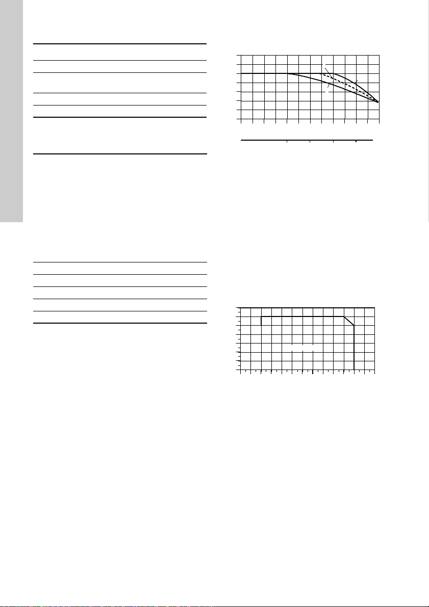
* Applies to pump version F
5.1 Ambient temperature
Motor power
[kW]
0.06 - 0.18 Siemens - +40 1000 1
0.25 - 0.55 MG - +40 1000 1
0.75 MG IE2 +60 3500 2
1.1 - 22 MG IE2 +60 3500 2
30-45 Siemens IE2 +55 2750 3
If the ambient temperature exceeds the above
temperature values or the pump is installed at an
altitude exceeding the above altitude values, the
motor must not be fully loaded due to the risk of
overheating. Overheating may result from excessive
ambient temperatures or the low density and
consequently low cooling effect of the air.
Motor make
Motor efficiency class
Max. ambient
temperature at full load
In such cases, it may be necessary to use a motor
with a higher rated output.
+90
(120*)
TM04 4914 2209
Fig. 3 Relationship between motor output (P2)
and ambient temperature/altitude
Example: A pump with a 1.1 kW IE2 MG motor: If
this pump is installed 4750 m above sea level, the
motor must not be loaded more than 88 % of rated
output. At an ambient temperature of 75 °C, the
motor must not be loaded more that 78 % of rated
output. If the pump is installed 4750 m above sea
level at an ambient temperature of 75 °C, the motor
must not be loaded more than 88 % x 78 % = 68.6 %
of rated output.
[°C]
Max. altitude above sea level
[m]
Pos. in output curve in fig. 3
5.2 Maximum permissible operating pressure and liquid temperature for the shaft seal
TM02 7854 4303
Fig. 4 MTR 1s to 64
6
Page 7

5.3 Minimum flow rate
40 50 60 70 80 90 100 110 120
t [°C]
0
10
20
30
Qmin
[%]
Caution
Caution
Caution
Vertical Horizontal
Due to the risk of overheating, the pump should not
be used at flows below the minimum flow rate.
The curve below shows the minimum flow rate as a
percentage of the nominal flow rate in relation to the
liquid temperature.
Fig. 5 Minimum flow rate in relation to
temperature
Note: The pump must never operate against a
closed discharge valve.
5.4 Electrical data
See motor nameplate.
5.5 Maximum number of starts
Motor size
[kW]
0.06 - 0.18 100
0.25 - 2.2 250
3-4 100
5.5 - 11 50
15-22 40
30-45 8
Recommended maximum
number of starts per hour
6. Installation
Warning
The pump must be installed so that
persons cannot accidentally come into
contact with the hot surface of the motor.
6.1 Pump location
The pump is designed for tank mounting in vertical
and horizontal position. However, only MTR version
H and MTRE version H are suitable for horizontal
mounting.
The pump is positioned in a hole cut into the tank
and is secured to the tank by four hexagon head
screws through the holes in the mounting flange.
TM04 5693 3809
Fig. 6 Vertical and horizontal installation
On horizontally installed MTR, MTRE pumps with
motors from 5.5 kW and up the motors have feet and
must be supported.
Fig. 7 Horizontally installed MTR with foot
English (GB)
TM01 4990 1399TM04 5755 3809
For horizontally mounted pumps ensure a
sufficient sealing between pump flange
and tank. A sealing gasket will usually
suffice.
Before changing shaft seals for
horizontally mounted pumps, drain the
tank.
MTR 32, 45 and 64 pumps can only be
installed in vertical position.
7
Page 8

English (GB)
D1
D2
D3
4 x X
C
L
B
A
25 mm
B
A
25 mm
A
25 mm
Fig. 8 Vertical installation
Mounting flange dimensions:
Pump type D1 D2 D3 L C X
CRK 2, 4 140 160 180 100
MTR 1s, 1,
3, 5
MTR 10,
15, 20
140 160 180 100
200 225 250 125
MTR 32 190 220 250 150 DN 65 ∅12
MTR 45,
64
240 265 290 165 DN 80 ∅12
6.2 Suction conditions
The bottom of the pump strainer must be at least 25
mm above the bottom of the tank.
The pumps are designed to provide full performance
down to a level of A mm above the bottom of the
strainer.
At a liquid level between A and B mm above the
bottom of the strainer, the built-in priming screw will
protect the pump against dry running.
Note: MTR 32, 45 and 64 pumps have no priming
screw.
Rp 1 1/4
G 1 1/4
Rp 1 1/4
G 1 1/4
Rp 2
G 2
∅7.5
∅9.5
∅9
TM05 7223 0813TM05 7224 0813TM05 7225 0813
Fig. 9 CRK 2, 4 and MTR 1s, 1, 3, 5
TM02 8042 4503
Fig. 10 MTR 10, 15, 20
Fig. 11 MTR 32, 45, 64
Pump type A [mm] B [mm]
CRK 2, 4 and MTR 1s, 1, 3, 5 41 28
MTR 10, 15, 20 50 25
MTR 32, 45, 64 70 -
8
Page 9

7. Electrical connection
0˚
90˚
180˚
270˚
Caution
The electrical connection should be carried out by an
authorized electrician in accordance with local
regulations.
The electrical connection should be carried out as
shown in the wiring diagram inside the terminal box
cover.
Warning
Before removing the terminal box cover
and before any removal/dismantling of the
pump, make sure that the power supply
has been switched off.
The pump must be connected to an
external mains switch with a minimum
contact gap of 3 mm in all poles.
The operating voltage and frequency are marked on
the pump nameplate. Please make sure that the
motor is suitable for the power supply on which it will
be used.
Single-phase Grundfos motors incorporate a
thermal switch and require no additional motor
protection.
Three-phase motors must be connected to a motorprotective circuit breaker.
The terminal box can be turned to four positions, in
90 ° steps. See fig. 12.
1. If necessary, remove the coupling guards. Do not
remove the coupling.
2. Remove the bolts securing the motor to the
pump.
3. Turn the motor to the required position.
4. Replace and tighten the bolts.
5. Replace the coupling guards.
7.1 Frequency converter operation
7.1.1 Motors supplied by Grundfos
All three-phase motors supplied by Grundfos can be
connected to a frequency converter.
Depending on the frequency converter type, this may
cause increased acoustic noise from the motor.
Furthermore, it may cause the motor to be exposed
to detrimental voltage peaks.
Grundfos motors, types MG 71 and MG 80
as well as MG 90 (1.5 kW, 2-pole), for
supply voltages up to and including 440 V
(see motor nameplate), must be protected
against voltage peaks higher than 650 V
(peak value) between the supply terminals.
We recommend to protect all other motors against
voltage peaks higher than 850 V.
The above disturbances, i.e. both increased acoustic
noise and detrimental voltage peaks, can be
eliminated by fitting an LC filter between the
frequency converter and the motor.
For further information, please contact the frequency
converter or motor supplier.
7.2 Other motor makes
If other motors makes than those supplied by
Grundfos are used, contact Grundfos or the motor
manufacturer.
English (GB)
TM00 4257 2294
Fig. 12 Terminal box positions
9
Page 10

8. Start-up
Caution
Air vent valve
English (GB)
Warning
Pay attention to the direction of the vent
hole and take care to ensure that the
escaping water does not cause injury to
persons or damage to the motor or other
components.
8.1 Before starting the pump
• Make sure that all pipe connections are tight.
• Make sure that the pump is partly filled with liquid
(partly submerged).
• Make sure that the strainer is not blocked by
impurities.
8.2 Starting the pump
1. Close the isolating valve on the discharge side of
the pump.
2. If the pump is fitted with an air vent valve, this
valve must be opened. See fig. 13.
9. Maintenance
Warning
Before starting work on the pump, make
sure that all power supplies to the pump
have been switched off and that they
cannot be accidentally switched on.
Pump bearings and shaft seal are maintenance-free.
Motor bearings
Motors not fitted with grease nipples are
maintenance-free.
Motors fitted with grease nipples should be
lubricated with a high-temperature, lithium-based
grease. See the instructions on the fan cover.
In the case of seasonal operation (motor is idle for
more than 6 months of the year), we recommend to
grease the motor when the pump is taken out of
operation.
Depending on the ambient temperature, the motor
bearings must be replaced or lubricated according to
the table below. The table applies to 2-pole motors.
The number of operating hours stated for bearing
replacement are guidelines only.
Fig. 13 Position of the air vent valve
3. See the correct direction of rotation of the pump
on the motor fan cover or on the coupling guard.
When seen from the top, the pump should rotate
counter-clockwise.
4. Start the pump and check the direction of
rotation.
5. Open the discharge pipe isolating valve a little.
6. If the pump is fitted with an air vent valve, this
valve must be closed when a steady flow of liquid
runs out of it.
7. Completely open the discharge pipe isolating
valve.
The pump has now been vented and is ready for
operation.
Do not run the pump against closed
discharge valve for more than approx. 5
minutes as this will cause an increase in
temperature/formation of steam in the
pump which may cause damage to the
pump.
Motor
size
[kW]
0.37 - 0.75 18000 - - - -
1.1 - 7.5 20000 15500 12500 10000 7500
TM01 6428 2399
Motor
size
[kW]
11 - 18.5 4500 3400 2500 1700 1100
22 4000 3100 2300 1500 1000
30-55 4000 3000 2000 1500 -
75 2000 1500 1000 500 -
Intervals for 4-pole motors are twice as long as those
for 2-pole motors.
If the ambient temperature is lower than 40 °C,
bearings must be replaced/lubricated at the intervals
mentioned under 40 °C.
Bearing replacement interval
[operating hours]
40 °C 45 °C 50 °C 55 °C 60 °C
Lubrication interval
[operating hours]
40 °C 45 °C 50 °C 55 °C 60 °C
10
Page 11

9.1 Filters
LpA [dB(A)]
Chip trays, filters, etc. should be cleaned at regular
intervals to ensure a correct flow of liquid.
9.2 Periodic checks
At regular intervals, depending on the conditions and
time of operation, the following checks should be
made:
• Check the quantity of liquid and operating
pressure.
• Check that there are no leaks.
• Check that the motor is not overheating.
• Check the tripping function of the motorprotective circuit breaker.
• Check that all controls are operating
satisfactorily.
If the above checks do not reveal any abnormal
operating details, no further checks are necessary.
Should any faults be found, check the symptoms
according to section 12. Fault finding.
10. Service
Warning
If a pump has been used for a liquid which
is injurious to health or toxic, the pump will
be classified as contaminated.
If Grundfos is requested to service the pump,
Grundfos must be contacted with details about the
pumped liquid, etc. before the pump is returned for
service. Otherwise Grundfos can refuse to accept
the pump for service.
Possible costs of returning the pump are paid by the
customer.
However, any application for service (no matter to
whom it may be made) must include details about
the pumped liquid if the pump has been used for
liquids which are injurious to health or toxic.
10.1 Service kits
Service kits for CRK and MTR, see https://productselection.grundfos.com/ or Service Kit Catalogue.
10.2 Coupling adjustment
For adjustment of coupling in CRK and MTR 1s to
20, see page 14.
For adjustment of coupling in MTR 32, 45, 64, see
page 15.
11. Sound pressure level
The table below shows airborne noise emitted by
CRK and MTR pumps with motors fitted by
Grundfos.
Motor
[kW]
0.37 50 55
0.55 50 53
0.75 50 54
1.1 52 57
1.5 54 59
2.2 54 59
3.0 55 60
4.0 62 66
5.5 60 65
7.5 60 65
11 60 65
15 60 65
18.5 60 65
22 66 70
30 71 75
37 71 75
45 71 75
50 Hz 60 Hz
English (GB)
11
Page 12

12. Fault finding
English (GB)
Warning
Before starting work on the pump, make
sure that all power supplies to the pump
have been switched off and that they
cannot be accidentally switched on.
Fault Cause Remedy
1. Motor does not run
when started.
2. Motor-protective
circuit breaker trips
out immediately
when power supply
is switched on.
3. Motor-protectivecircuit breaker trips
out occasionally.
4. Motor-protectivecircuit breaker has
not tripped out but
the pump does not
run.
5. Pump runs but
gives no liquid or
pump performance
is not constant.
6. Leakage in shaft
seal.
7. Noise. a) Cavitation. Check the suction conditions.
a) Power supply failure. Connect the power supply.
b) Fuses are blown. Replace fuses.
c) Motor-protective circuit breaker has
tripped out.
d) Thermal protection has tripped out. Reactivate the thermal protection.
e) Main contacts in motor-protective
circuit breaker are not making contact
or the coil is faulty.
f) Control circuit is defective. Repair the control circuit.
g) Motor is defective. Replace the motor.
a) One fuse blown/automatic circuit
breaker has tripped out.
b) Contacts in motor-protective circuit
breaker are faulty.
c) Cable connection is loose or faulty. Fasten or replace the cable
d) Motor winding is defective. Replace the motor.
e) Pump mechanically blocked. Remove the mechanical blocking of
f) Motor-protective circuit breaker
overload setting is too low.
a) Motor-protective circuit breaker
overload setting is too low.
b) Low voltage at peak times. Reestablish constant power supply.
a) Check 1 a), b), d), e) and f).
a) Pump strainer partly blocked by
impurities.
b) Liquid level in tank too low. Increase the liquid level.
c) Pump draws in air. Check the suction conditions.
a) Shaft seal is defective.
b) Pump does not rotate freely (frictional
resistance) because of incorrect
pump shaft position.
c) Frequency converter operation. See section 7.1 Frequency converter
Reactivate the motor-protective
circuit breaker.
Replace contacts or magnetic coil.
Replace fuse/cut in the circuit
breaker.
Replace motor-protective circuit
breaker contacts.
connection.
the pump.
Set the motor-protective circuit
breaker correctly.
Set the motor-protective circuit
breaker correctly.
Clean the strainer.
Replace the shaft seal.
Adjust the pump shaft.
operation.
12
Page 13

13. Disposal
This product or parts of it must be disposed of in an
environmentally sound way:
1. Use the public or private waste collection service.
2. If this is not possible, contact the nearest
Grundfos company or service workshop.
Subject to alterations.
English (GB)
13
Page 14

Appendix 1
M6: 13 Nm
M8: 31 Nm
M10: 62 Nm
M5: 2.5 Nm
Appendix
CRK and MTR 1s to 20
TM02 8050 4503
TM02 8052 4503
TM02 8051 4503
TM02 7420 3403
14
Page 15

MTR 32, 45, 64
1.7 mm
M10 x 2.5: 62 Nm
MTR32
MTR45
MTR64
Appendix
TM01 9785 3100
TM01 9788 3100
TM01 9786 3100
15
Page 16

Declaration of conformity
Declaration of conformity 2
GB: EC/EU declaration of conformity
We, Grundfos, declare under our sole responsibility that the products
CRK, MTR, to which the declaration below relates, are in conformity
with the Council Directives listed below on the approximation of the
laws of the EC/EU member states.
Note: There are two sets of Council Directives and standards listed
below. One set applies until and including 19th April 2016. The other
set applies from 20th April 2016 and onwards.
DE: EG-/EU-Konformitätserklärung
Wir, Grundfos, erklären in alleiniger Verantwortung, dass die
Produkte CRK, MTR, auf die sich diese Erklärung beziehen, mit den
folgenden Richtlinien des Rates zur Angleichung der
Rechtsvorschriften der EG-/EU-Mitgliedsstaaten übereinstimmen.
Hinweis: Nachfolgend sind zwei Gruppen aus Richtlinien des Rates
und Standards aufgeführt. Eine Gruppe gilt bis einschließlich 19. April
2016. Die andere Gruppe gilt ab dem 20. April 2016.
FR: Déclaration de conformité CE/UE
Nous, Grundfos, déclarons sous notre seule responsabilité, que les
produits CRK, MTR, auxquels se réfère cette déclaration, sont
conformes aux Directives du Conseil concernant le rapprochement
des législations des États membres CE/UE relatives aux normes
énoncées ci-dessous.
Remarque : Deux groupes de Directives du Conseil et normes sont
énoncés ci-dessous. Un groupe s'applique jusqu'au 19 avril 2016
inclus. L'autre groupe entrera en vigueur le 20 avril 2016.
PL: Deklaracja zgodności WE/UE
My, Grundfos, oświadczamy z pełną odpowiedzialnością, że nasze
produkty CRK, MTR, których deklaracja niniejsza dotyczy, są zgodne
z następującymi dyrektywami Rady w sprawie zbliżenia przepisów
prawnych państw członkowskich.
Uwaga: Poniżej podano dwa zestawy dyrektyw i norm. Pierwszy
zestaw obowiązuje do 19 kwietna 2016 r. włącznie. Drugi zacznie
obowiązywać 20 kwietnia 2016 r.
These Directives and standards apply until and including 19th April
2016:
– Machinery Directive (2006/42/EC).
Standard used:
EN 809:1998 + A1:2009.
– EMC Directive (2004/108/EC).
– Ecodesign Directive (2009/125/EC).
Electric motors:
Commission Regulation No 640/2009.
Applies only to three-phase Grundfos motors marked IE2 or IE3.
See motor nameplate.
Standard used EN 60034-30:2009.
– Ecodesign Directive (2009/125/EC).
Water pumps:
Commission Regulation No 547/2012.
Applies only to water pumps marked with the minimum efficiency
index MEI. See pump nameplate.
CZ: Prohlášení o shodě EU
My firma Grundfos prohlašujeme na svou plnou odpovědnost, že
výrobky CRK, MTR, na které se toto prohlášení vztahuje, jsou
v souladu s níže uvedenými ustanoveními směrnice Rady pro
sblížení právních předpisů členských států Evropského společenství.
Poznámka: Níže jsou uvedeny dvě sady směrnic Rady a standardů.
První sada je platná do 19. dubna 2016 (včetně). Druhá sada platí od
20. dubna 2016.
ES: Declaración de conformidad de la CE/UE
Grundfos declara, bajo su exclusiva responsabilidad, que los
productos CRK, MTR a los que hace referencia la siguiente
declaración cumplen lo establecido por las siguientes Directivas del
Consejo sobre la aproximación de las legislaciones de los Estados
miembros de la CE/UE.
Nota: A continuación se recogen dos conjuntos de normas y
Directivas del Consejo. Uno de ellos es válido hasta el 19 de abril de
2016. El otro es válido a partir del 20 de abril de 2016.
IT: Dichiarazione di conformità CE/UE
Grundfos dichiara sotto la sua esclusiva responsabilità che i prodotti
CRK, MTR, ai quale si riferisce questa dichiarazione, sono conformi
alle seguenti direttive del Consiglio riguardanti il riavvicinamento delle
legislazioni degli Stati membri CE/UE.
Nota: Di seguito sono elencate due serie di direttive del Consiglio e
norme. Una serie si applca fino al19 aprile 2016 (incluso). La seconda
serie si applica a partire dal 20 aprile 2016.
RU: Декларация о соответствии нормам
ЕЭС/ЕС
Мы, компания Grundfos, со всей ответственностью заявляем, что
изделия CRK, MTR, к которым относится нижеприведённая
декларация, соответствуют нижеприведённым Директивам
Совета Евросоюза о тождественности законов стран-членов
ЕЭС/ЕС.
Примечание: Существует два комплекта Директив Совета
Евросоюза и стандартов, перечисленных ниже. Один комплект
применяется до 19 апреля 2016 г. включительно. Второй комплект
применяется начиная с 20 апреля 2016 г.
These Directives and standards apply from 20th April 2016 and
onwards:
– Machinery Directive (2006/42/EC).
Standard used:
EN 809:1998 + A1:2009
– EMC Directive (2014/30/EU).
– Ecodesign Directive (2009/125/EC).
Electric motors:
Commission Regulation No 640/2009.
Applies only to three-phase Grundfos motors marked IE2 or IE3.
See motor nameplate.
Standard used EN 60034-30:2009.
– Ecodesign Directive (2009/125/EC).
Water pumps:
Commission Regulation No 547/2012.
Applies only to water pumps marked with the minimum efficiency
index MEI. See pump nameplate.
This EC/EU declaration of conformity is only valid when published as
part of the Grundfos installation and operating instructions
(publication number 96496966 0316).
Székesfehérvár, 3 February 2016
16
Róbert Kis
Engineering Manager
GRUNDFOS Holding A/S
Poul Due Jensens Vej 7
8850 Bjerringbro, Denmark
Person authorised to compile the technical file and
empowered to sign the EC/EU declaration of conformity.
Page 17

17
Page 18

Grundfos companies
Argentina
Bombas GRUNDFOS de Argentina S.A.
Ruta Panamericana km. 37.500 Centro
Industrial Garin
1619 Garín Pcia. de B.A.
Phone: +54-3327 414 444
Telefax: +54-3327 45 3190
Australia
GRUNDFOS Pumps Pty. Ltd.
P.O. Box 2040
Regency Park
South Australia 5942
Phone: +61-8-8461-4611
Telefax: +61-8-8340 0155
Austria
GRUNDFOS Pumpen Vertrieb
Ges.m.b.H.
Grundfosstraße 2
A-5082 Grödig/Salzburg
Tel.: +43-6246-883-0
Telefax: +43-6246-883-30
Belgium
N.V. GRUNDFOS Bellux S.A.
Boomsesteenweg 81-83
B-2630 Aartselaar
Tél.: +32-3-870 7300
Télécopie: +32-3-870 7301
Belarus
Представительство ГРУНДФОС в
Минске
220125, Минск
ул. Шафарнянская, 11, оф. 56, БЦ
«Порт»
Тел.: +7 (375 17) 286 39 72/73
Факс: +7 (375 17) 286 39 71
E-mail: minsk@grundfos.com
Bosna and Herzegovina
GRUNDFOS Sarajevo
Zmaja od Bosne 7-7A,
BH-71000 Sarajevo
Phone: +387 33 592 480
Telefax: +387 33 590 465
www.ba.grundfos.com
e-mail: grundfos@bih.net.ba
Brazil
BOMBAS GRUNDFOS DO BRASIL
Av. Humberto de Alencar Castelo
Branco, 630
CEP 09850 - 300
São Bernardo do Campo - SP
Phone: +55-11 4393 5533
Telefax: +55-11 4343 5015
Bulgaria
Grundfos Bulgaria EOOD
Slatina District
Iztochna Tangenta street no. 100
BG - 1592 Sofia
Tel. +359 2 49 22 200
Fax. +359 2 49 22 201
email: bulgaria@grundfos.bg
Canada
GRUNDFOS Canada Inc.
2941 Brighton Road
Oakville, Ontario
L6H 6C9
Phone: +1-905 829 9533
Telefax: +1-905 829 9512
China
GRUNDFOS Pumps (Shanghai) Co. Ltd.
10F The Hub, No. 33 Suhong Road
Minhang District
Shanghai 201106
PRC
Phone: +86 21 612 252 22
Telefax: +86 21 612 253 33
Croatia
GRUNDFOS CROATIA d.o.o.
Buzinski prilaz 38, Buzin
HR-10010 Zagreb
Phone: +385 1 6595 400
Telefax: +385 1 6595 499
www.hr.grundfos.com
Czech Republic
GRUNDFOS s.r.o.
Čajkovského 21
779 00 Olomouc
Phone: +420-585-716 111
Telefax: +420-585-716 299
Denmark
GRUNDFOS DK A/S
Martin Bachs Vej 3
DK-8850 Bjerringbro
Tlf.: +45-87 50 50 50
Telefax: +45-87 50 51 51
E-mail: info_GDK@grundfos.com
www.grundfos.com/DK
Estonia
GRUNDFOS Pumps Eesti OÜ
Peterburi tee 92G
11415 Tallinn
Tel: + 372 606 1690
Fax: + 372 606 1691
Finland
OY GRUNDFOS Pumput AB
Trukkikuja 1
FI-01360 Vantaa
Phone: +358-(0) 207 889 500
Telefax: +358-(0) 207 889 550
France
Pompes GRUNDFOS Distribution S.A.
Parc d’Activités de Chesnes
57, rue de Malacombe
F-38290 St. Quentin Fallavier (Lyon)
Tél.: +33-4 74 82 15 15
Télécopie: +33-4 74 94 10 51
Germany
GRUNDFOS GMBH
Schlüterstr. 33
40699 Erkrath
Tel.: +49-(0) 211 929 69-0
Telefax: +49-(0) 211 929 69-3799
e-mail: infoservice@grundfos.de
Service in Deutschland:
e-mail: kundendienst@grundfos.de
Greece
GRUNDFOS Hellas A.E.B.E.
20th km. Athinon-Markopoulou Av.
P.O. Box 71
GR-19002 Peania
Phone: +0030-210-66 83 400
Telefax: +0030-210-66 46 273
Hong Kong
GRUNDFOS Pumps (Hong Kong) Ltd.
Unit 1, Ground floor
Siu Wai Industrial Centre
29-33 Wing Hong Street &
68 King Lam Street, Cheung Sha Wan
Kowloon
Phone: +852-27861706 / 27861741
Telefax: +852-27858664
Hungary
GRUNDFOS Hungária Kft.
Park u. 8
H-2045 Törökbálint,
Phone: +36-23 511 110
Telefax: +36-23 511 111
India
GRUNDFOS Pumps India Private
Limited
118 Old Mahabalipuram Road
Thoraipakkam
Chennai 600 096
Phone: +91-44 2496 6800
Indonesia
PT. GRUNDFOS POMPA
Graha Intirub Lt. 2 & 3
Jln. Cililitan Besar No.454. Makasar,
Jakarta Timur
ID-Jakarta 13650
Phone: +62 21-469-51900
Telefax: +62 21-460 6910 / 460 6901
Ireland
GRUNDFOS (Ireland) Ltd.
Unit A, Merrywell Business Park
Ballymount Road Lower
Dublin 12
Phone: +353-1-4089 800
Telefax: +353-1-4089 830
Italy
GRUNDFOS Pompe Italia S.r.l.
Via Gran Sasso 4
I-20060 Truccazzano (Milano)
Tel.: +39-02-95838112
Telefax: +39-02-95309290 / 95838461
Japan
GRUNDFOS Pumps K.K.
Gotanda Metalion Bldg., 5F,
5-21-15, Higashi-gotanda
Shiagawa-ku, Tokyo
141-0022 Japan
Phone: +81 35 448 1391
Telefax: +81 35 448 9619
Korea
GRUNDFOS Pumps Korea Ltd.
6th Floor, Aju Building 679-5
Yeoksam-dong, Kangnam-ku, 135-916
Seoul, Korea
Phone: +82-2-5317 600
Telefax: +82-2-5633 725
Latvia
SIA GRUNDFOS Pumps Latvia
Deglava biznesa centrs
Augusta Deglava ielā 60, LV-1035, Rīga,
Tālr.: + 371 714 9640, 7 149 641
Fakss: + 371 914 9646
Lithuania
GRUNDFOS Pumps UAB
Smolensko g. 6
LT-03201 Vilnius
Tel: + 370 52 395 430
Fax: + 370 52 395 431
Page 19

Malaysia
GRUNDFOS Pumps Sdn. Bhd.
7 Jalan Peguam U1/25
Glenmarie Industrial Park
40150 Shah Alam
Selangor
Phone: +60-3-5569 2922
Telefax: +60-3-5569 2866
Mexico
Bombas GRUNDFOS de México S.A. de
C.V.
Boulevard TLC No. 15
Parque Industrial Stiva Aeropuerto
Apodaca, N.L. 66600
Phone: +52-81-8144 4000
Telefax: +52-81-8144 4010
Netherlands
GRUNDFOS Netherlands
Veluwezoom 35
1326 AE Almere
Postbus 22015
1302 CA ALMERE
Tel.: +31-88-478 6336
Telefax: +31-88-478 6332
E-mail: info_gnl@grundfos.com
New Zealand
GRUNDFOS Pumps NZ Ltd.
17 Beatrice Tinsley Crescent
North Harbour Industrial Estate
Albany, Auckland
Phone: +64-9-415 3240
Telefax: +64-9-415 3250
Norway
GRUNDFOS Pumper A/S
Strømsveien 344
Postboks 235, Leirdal
N-1011 Oslo
Tlf.: +47-22 90 47 00
Telefax: +47-22 32 21 50
Poland
GRUNDFOS Pompy Sp. z o.o.
ul. Klonowa 23
Baranowo k. Poznania
PL-62-081 Przeźmierowo
Tel: (+48-61) 650 13 00
Fax: (+48-61) 650 13 50
Portugal
Bombas GRUNDFOS Portugal, S.A.
Rua Calvet de Magalhães, 241
Apartado 1079
P-2770-153 Paço de Arcos
Tel.: +351-21-440 76 00
Telefax: +351-21-440 76 90
Romania
GRUNDFOS Pompe România SRL
Bd. Biruintei, nr 103
Pantelimon county Ilfov
Phone: +40 21 200 4100
Telefax: +40 21 200 4101
E-mail: romania@grundfos.ro
Russia
ООО Грундф ос Россия
109544, г. Москва, ул. Школьная, 39-
41, стр. 1
Тел. (+7) 495 564-88-00 (495) 737-3000
Факс (+7) 495 564 88 11
E-mail grundfos.moscow@grundfos.com
Serbia
Grundfos Srbija d.o.o.
Omladinskih brigada 90b
11070 Novi Beograd
Phone: +381 11 2258 740
Telefax: +381 11 2281 769
www.rs.grundfos.com
Singapore
GRUNDFOS (Singapore) Pte. Ltd.
25 Jalan Tukang
Singapore 619264
Phone: +65-6681 9688
Telefax: +65-6681 9689
Slovakia
GRUNDFOS s.r.o.
Prievozská 4D
821 09 BRATISLAVA
Phona: +421 2 5020 1426
sk.grundfos.com
Slovenia
GRUNDFOS LJUBLJANA, d.o.o.
Leskoškova 9e, 1122 Ljubljana
Phone: +386 (0) 1 568 06 10
Telefax: +386 (0)1 568 06 19
E-mail: tehnika-si@grundfos.com
South Africa
GRUNDFOS (PTY) LTD
Corner Mountjoy and George Allen
Roads
Wilbart Ext. 2
Bedfordview 2008
Phone: (+27) 11 579 4800
Fax: (+27) 11 455 6066
E-mail: lsmart@grundfos.com
Spain
Bombas GRUNDFOS España S.A.
Camino de la Fuentecilla, s/n
E-28110 Algete (Madrid)
Tel.: +34-91-848 8800
Telefax: +34-91-628 0465
Sweden
GRUNDFOS AB
Box 333 (Lunnagårdsgatan 6)
431 24 Mölndal
Tel.: +46 31 332 23 000
Telefax: +46 31 331 94 60
Switzerland
GRUNDFOS Pumpen AG
Bruggacherstrasse 10
CH-8117 Fällanden/ZH
Tel.: +41-44-806 8111
Telefax: +41-44-806 8115
Tai wan
GRUNDFOS Pumps (Taiwan) Ltd.
7 Floor, 219 Min-Chuan Road
Taichung, Taiwan, R.O.C.
Phone: +886-4-2305 0868
Telefax: +886-4-2305 0878
Thailand
GRUNDFOS (Thailand) Ltd.
92 Chaloem Phrakiat Rama 9 Road,
Dokmai, Pravej, Bangkok 10250
Phone: +66-2-725 8999
Telefax: +66-2-725 8998
Turkey
GRUNDFOS POMPA San. ve Tic. Ltd.
Sti.
Gebze Organize Sanayi Bölgesi
Ihsan dede Caddesi,
2. yol 200. Sokak No. 204
41490 Gebze/ Kocaeli
Phone: +90 - 262-679 7979
Telefax: +90 - 262-679 7905
E-mail: satis@grundfos.com
Ukraine
Бізнес Центр Європа
Столичне шосе, 103
м. Київ, 03131, Україна
Телефон : (+38 044) 237 04 00
Факс.: (+38 044) 237 04 01
E-mail: ukraine@grundfos.com
United Arab Emirates
GRUNDFOS Gulf Distribution
P.O. Box 16768
Jebel Ali Free Zone
Dubai
Phone: +971 4 8815 166
Telefax: +971 4 8815 136
United Kingdom
GRUNDFOS Pumps Ltd.
Grovebury Road
Leighton Buzzard/Beds. LU7 4TL
Phone: +44-1525-850000
Telefax: +44-1525-850011
U.S.A.
GRUNDFOS Pumps Corporation
17100 West 118th Terrace
Olathe, Kansas 66061
Phone: +1-913-227-3400
Telefax: +1-913-227-3500
Uzbekistan
Grundfos Tashkent, Uzbekistan The
Representative Office of Grundfos
Kazakhstan in Uzbekistan
38a, Oybek street, Tashkent
Телефон: (+998) 71 150 3290 / 71 150
3291
Факс: (+998) 71 150 3292
Addresses Revised 25.01.2016
Grundfos companies
Page 20

96496966 0316
ECM: 1181099
www.grundfos.com
© Copyright Grundfos Holding A/S
owned by Grundfos Holding A/S or Grundfos A/ S, Denmark. All rights reserved worldwide.
The name Grundfos, the Grundfos logo, and be think innovate are registered trademarks
 Loading...