

Grundfos MGE Series, MGE 71 Series, MGE 80 Series, MGE 90 Series, MGE 100 Series Installation And Operating Instructions Manual
...Page 1
MGE motors
Installation and operating instructions
GRUNDFOS INSTRUCTIONS
Page 2

English (GB) Installation and operating instructions
English (GB)
Original installation and operating instructions
CONTENTS
Page
1. Symbols used in this document
2. Abbreviations and definitions
3. General description
3.1 Radio communication
3.2 Battery
4. Identification
4.1 Nameplate
4.2 Type key
5. Receiving the product
5.1 Transporting the product
5.2 Inspecting the product
6. Mechanical installation
6.1 Handling the product
6.2 Mounting
6.3 Cable entries
6.4 Ensuring motor cooling
6.5 Outdoor installation
6.6 Drain holes
7. Electrical installation
7.1 Protection against electric shock,
indirect contact
7.2 Cable requirements
7.3 Mains supply
7.4 Additional protection
7.5 Functional modules
7.6 Connection terminals on functional
modules
7.7 Signal cables
7.8 Bus connection cable
8. Operating conditions
8.1 Maximum number of starts and stops
8.2 Ambient temperature
8.3 Installation altitude
8.4 Humidity
8.5 Motor cooling
9. User interfaces
9.1 Basic control panel
9.2 Standard control panel
9.3 Advanced control panel
9.4 Grundfos GO
9.5 R100 remote control
10. Description of functions
10.1 ""Setpoint""
10.2 ""Operating mode""
10.3 ""Set manual speed""
10.4 "Control mode"
10.5 ""Analog inputs""
10.6 ""Pt100/1000 inputs""
10.7 "Digital inputs"
10.8 ""Digital inputs/outputs""
2
10.9 "Signal relay" (""Relay outputs"")
10.10 ""Analog output""
10.11 "Controller" (""Controller settings"")
10.12 ""Operating range""
10.13 ""External setpoint function""
3
10.14 "Predefined setpoints"
3
10.15 ""Limit-exceeded function""
4
10.16 "Ramps"
4
10.17 "Direction of rotation"
4
10.18 "Skip band"
10.19 ""Standstill heating""
5
10.20 ""Motor bearing monitoring""
5
10.21 "Service"
6
10.22 "Number" (""Pump number"")
7
10.23 "Radio communication"
7
7
10.24 ""Language""
7
10.25 "Date and time" (""Set date and time"")
7
10.26 "Unit configuration" (""Units"")
7
10.27 "Buttons on product" (""Enable/disable
7
10.28 ""Delete history""
7
10.29 ""Define Home display""
8
10.30 ""Display settings""
8
10.31 "Store settings" (""Store actual
8
10.32 "Recall settings" (""Recall stored
8
9
10.33 "Pump name" (motor name)
9
10.34 "Connection code"
10
10.35 ""Run start-up guide""
11
10.36 ""Alarm log""
10.37 ""Warning log""
11
10.38 ""Assist""
16
10.39 ""Assisted pump setup"" (Assisted motor
16
17
10.40 ""Setup, analog input""
17
10.41 ""Setting of date and time""
17
10.42 ""Setup of multi-pump system""
17
17
10.43 ""Description of control mode""
17
10.44 ""Assisted fault advice""
18
11. Bus signal
18
12. Priority of settings
19
13. Grundfos Eye
21
14. Installing a communication interface
26
30
15. Identification of functional module
32
16. Identification of control panel
32
17. Changing the position of the control
32
32
18. Servicing the product
32
32
19. Cleaning the product
33
20. Signal relays
34
21. Megging
35
(""Enable/disable radio comm."")
settings"")
settings"")
settings"")
setup)
(Multimotor)
module
panel
36
36
37
37
37
40
41
42
42
42
42
42
43
43
43
43
43
43
43
44
44
44
44
44
44
44
45
45
45
45
45
46
46
46
49
49
49
50
51
52
54
54
55
56
56
57
58
Page 3
22. Technical data, single-phase motors
22.1 Supply voltage
22.2 Leakage current
23. Technical data, three-phase motors
23.1 Supply voltage
23.2 Leakage current (AC)
24. Inputs and outputs
25. Other technical data
25.1 Sound pressure level
26. Disposing of the product
Prior to installation, read this document.
Installation and operation must comply
with local regulations and accepted codes
of good practice.
1. Symbols used in this document
DANGER
Indicates a hazardous situation which, if
not avoided, will result in death or serious
personal injury.
WARNING
Indicates a hazardous situation which, if
not avoided, could result in death or
serious personal injury.
CAUTION
Indicates a hazardous situation which, if
not avoided, could result in minor or
moderate personal injury.
Notes or instructions that make the work
easier and ensure safe operation.
If these instructions are not observed, it
may result in malfunction or damage to the
equipment.
A blue or grey circle with a white graphical
symbol indicates that an action must be
taken.
A red or grey circle with a diagonal bar,
possibly with a black graphical symbol,
indicates that an action must not be taken
or must be stopped.
2. Abbreviations and definitions
58
58
AI Analog input.
58
AL Alarm, out of range at lower limit.
58
58
AO Analog output.
58
AU Alarm, out of range at upper limit.
59
CIM Communication interface module.
60
61
Current
sinking
61
Current
sourcing
DI Digital input.
DO Digital output.
ELCB Earth leakage circuit breaker.
FM Functional module.
GDS
GENIbus
GFCI Ground fault circuit interrupter.
GND Ground
Grundfos Eye Status indicator light.
LIVE
OC
PE Protective earth.
PELV
RCD Residual-current device
SELV
The ability to draw current into the
terminal and guide it towards earth
in the internal circuitry.
The ability to push current out of
the terminal and into an external
load which must return it to earth.
Grundfos Digital Sensor.
Factory-fitted sensor in some
Grundfos pumps.
Proprietary Grundfos fieldbus
standard.
Low voltage with the risk of
electric shock if the terminals are
touched.
Open collector:
Configurable open-collector
output.
Protective extra-low voltage.
A voltage that cannot exceed ELV
under normal conditions and
under single-fault conditions,
except earth faults in other
circuits.
Safety extra-low voltage.
A voltage that cannot exceed ELV
under normal conditions and
under single-fault conditions,
including earth faults in other
circuits.
English (GB)
3
Page 4

3. General description
English (GB)
Grundfos MGE 71-160 are frequency-controlled
permanent-magnet motors for single-phase or
three-phase mains connection. The motors
incorporate a PI controller.
You can connect the motors to a signal from an
external sensor and a setpoint signal enabling
control in closed loop. You can also use the motors
for an open-loop system in which the setpoint signal
is used as a speed control signal.
The motors are intended for machines with a square
torque characteristic, such as ventilators and
centrifugal pumps.
The motors incorporate a control panel which is
available in various versions. See section 9. User
interfaces.
Detailed motor settings are made with the wireless
Grundfos R100 remote control or Grundfos GO.
Furthermore, you can read important operating
parameters via R100 or Grundfos GO.
The motors incorporate a functional module. The
functional module is available in various versions
with different inputs and outputs. See section
7.5 Functional modules.
You can fit the motors with a Grundfos CIM module.
A CIM module is an add-on communication interface
module. The CIM module enables data transmission
between the motor and an external system, for
example a BMS or SCADA system. The CIM module
communicates via fieldbus protocols.
You can connect several MGE motors together via
radio or bus communication to create a multimotor
system.
3.1 Radio communication
This product incorporates a radio module for remote
control which is a class 1 device and which you can
use anywhere in the EU without restrictions.
For use in USA and Canada, see Installation in the
USA and Canada on page 62.
Some variants of the product and products sold in
China and Korea have no radio module.
This product can communicate with Grundfos GO
and other MGE motors of the same type via the
built-in radio module.
3.2 Battery
A Li-ion battery is fitted in the FM 300 functional
module.
The Li-ion battery complies with the Battery Directive
(2006/66/EC). The battery does not contain mercury,
lead and cadmium.
4
Page 5
4. Identification
Env.Type :
Serial no :
SF CL:
PF:
PB
FM
HMIEff
n max:
CIMWgt
:
DE
:
kg
NDE
:
T
amb
:
:
FAA
V
~
P.C.
:
Made in Hungary
OUTPUT
VARIANT
INPUT
TEFC
Type
:
P.N.
:
U
in
:
I
1/1
:
f
in
HpHzP2
I
SF Amp:
rpm
:::
:
:
:
:
Xxxxxxxxxxx
E.P. Motor
DK - 8850 Bjerringbro, Denmark
A
Env.Type :
IP:
CL:
PF
PB
FM
HMIEff
n max:
CIM
Wgt
:
DE
:
kg
NDE
:
T
amb
:
:
CA
V
~
P.C.
:
Made in Hungary
OUTPUT
VARIANT
INPUT
Type
:
P.N.
:
U in:
I
1/1
:
f
in
kW
Hz
P2
rpm
:::
:
:
:
:
o
12
23
3456
2627 25
24
22 21
7 8 9 10
14 13
11 12
151617181920
DK - 8850 Bjerringbro, Denmark
- V
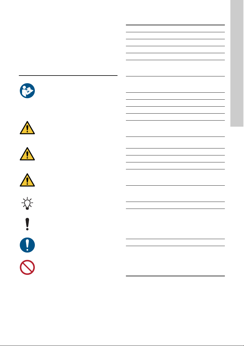
You can identify the motor by means of the
nameplate on the terminal box.
4.1 Nameplate
The motor nameplate is located on the side of the
terminal box. See fig. 1, pos. A.
Fig. 1 Nameplate location
Figure 2 shows the nameplate. The position
numbers refer to the table below.
Fig. 2 Nameplate, MGE motors
English (GB)
TM06 4924 3115
TM06 5553 4915
Pos. Description Pos. Description
1 Type designation 15 Country of origin
2 Product number 16 Human Machine Interface type
3 Drive-end bearing 17 CIM module type
4 Version number 18 Motor efficiency
5 Environmental type 19 Maximum motor speed [min
-1
]
6 Production code (year and week) 20 Maximum input current [A]
7 Supply voltage [V] 21 Mains frequency [Hz]
8 Rated power output [kW] 22
Enclosure class according to IEC
60034-5
9 Power board 23 Insulation class according to IEC 62114
10 Functional module type 24 Maximum ambient temperature [°C]
11 CE mark and approvals 25 Power factor
12 Part number of nameplate 26 Weight [kg]
13 Grundfos logo 27 Non-drive-end bearing
14 Grundfos company address
5
Page 6

4.2 Type key
English (GB)
Code Example MG E 71 M A 2- FT 85 -H A
Type of motor unit
[ ]
B
K
Complete motor with terminal box
Basic motor unit without terminal box
Kit for basic motor unit without terminal box
MG Motor Grundfos
E Electronic control
71
80
90
100
112
132
Frame size according to IEC (centre line height of motor shaft in mm,
foot-mounted motor)
160
[ ]
S
M
L
Size of foot
Not defined for frame sizes 71 and 80
Small
Medium
Large
Maximum motor power, P2 [kW]
A
B
C
D
A
B
C
D
E
F
G
H
1
2
4
[ ]
FT
FF
1)
1)
1)
1)
2)
2)
2)
2)
2)
2)
2)
2)
Maximum speed
5900 min
4000 min
2000/2200 min
Flange version
Foot-mounted (B3)
Tapped-hole flange
Free-hole flange
Length of
stator core
1450-2000
min
-1
1450-2200
min
30 0.37 - 0.75 1.1
45 0.55 - 1.1 1.5
60 0.75 - 1.5 2.2
85 1.1 - 2.2 70 - - 3.0 3.0
80 - 2.2 - 95 - - 4.0 4.0 / 4.6
100 1.5
1)
125 - 4.0 5.5 5.5 / 6.0
70 - - 7.5 7.5
80 - 5.5 - -
105 - 7.5 11.0 11.0
-1
-1
-1
-1
2900-4000
min
-1
4000-5900
min
3.0 - -
-1
Pitch circle diameter [mm], flange version
[ ]
H
I
J
B3
Model designation
Single-phase motor
Three-phase motors up to 2.2 KW
Three-phase motors from 1.5 to 11 kW
Version designation
A
1)
2)
First version
Frame size 71, 80, 90
Frame size 100, 112, 132, 160
6
Page 7
5. Receiving the product
D
50
5.1 Transporting the product
WARNING
Falling objects
Death or serious personal injury
- Secure the product during
transportation to prevent it from tilting or
falling down.
CAUTION
Crushing of feet
Minor or moderate personal injury
- Wear safety shoes when moving the
product.
• Motors from 2.2 to 5.5 kW: Do not stack more
than two motors in their original packaging.
• Motors from 5.5 to 11 kW: Do not stack the
motors.
5.2 Inspecting the product
Before you install the product, do the following.
1. Check that the product is as ordered.
2. Check that no visible parts have been damaged.
3. If parts are damaged or missing, contact your
local Grundfos sales company.
6. Mechanical installation
6.1 Handling the product
Observe local regulations setting limits for manual
lifting or handling. The motor weight is stated on the
nameplate.
CAUTION
Back injury
Minor or moderate personal injury
- Use lifting equipment.
6.2 Mounting
CAUTION
Crushing of feet
Minor or moderate personal injury
- Secure the product to a solid foundation
by bolts through the holes in the flange
or the base plate.
In order to maintain the UL mark,
additional requirements apply to the
equipment. See Installation in the USA
and Canada on page 62.
6.3 Cable entries
The cable entries are fitted with blanking plugs from
factory. You can order various cable glands from
Grundfos as accessory kits.
See the size of the cable entries in section 25. Other
technical data.
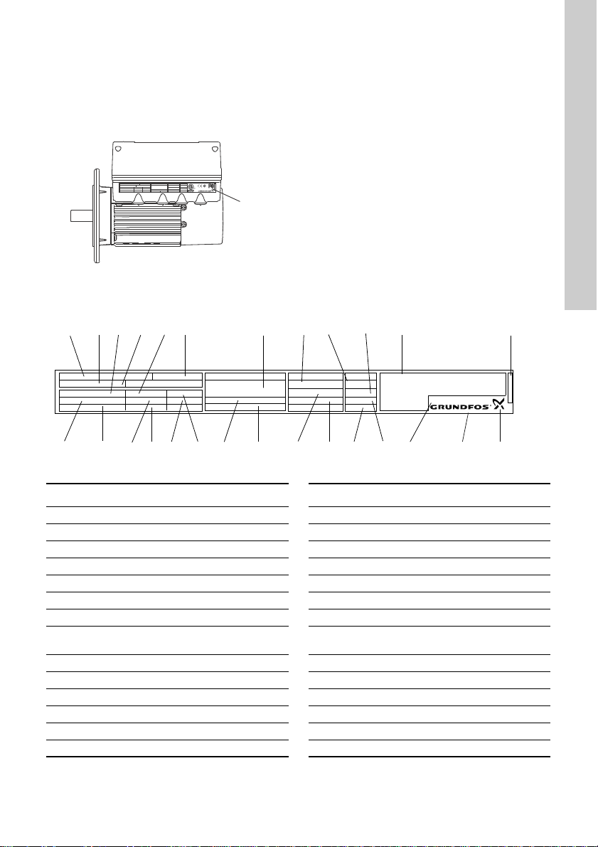
6.4 Ensuring motor cooling
Leave at least 50 mm between the end of the fan
cover and a wall or other fixed objects. See fig. 3.
Fig. 3 Minimum distance [mm]
English (GB)
TM06 4925 3115
CAUTION
Crushing of feet
Minor or moderate personal injury
- Wear safety shoes and attach lifting
equipment to the motor eyebolts when
handling the product.
Do not lift the product by the terminal box.
7
Page 8

6.5 Outdoor installation
B3 B14 B5
English (GB)
If you install the motor outdoors, provide the motor
with a suitable cover and open the drain holes to
avoid condensation on the electronic components.
See figures 4 and 5.
When fitting a cover to the motor, observe
the guideline in section 6.4 Ensuring motor
cooling.
The cover must be sufficiently large to ensure that
the motor is not exposed to direct sunlight, rain or
snow. Grundfos does not supply covers. We
therefore recommend that you have a cover built for
the specific application. In areas with high humidity,
we recommend that you connect the motor
permanently to the mains supply and activate the
built-in standstill heating function. See section
10.19 ""Standstill heating"".
Fig. 4 Examples of covers (not supplied by
Grundfos)
6.6 Drain holes
If you install the motor in moist surroundings or areas
with high humidity, the bottom drain hole must be
open. The enclosure class of the motor will then be
lower. This helps prevent condensation in the motor
as the motor becomes self-venting, and it allows
water and humid air to escape.
The motor has a plugged drain hole on the drive
side. You can turn the flange 90 ° to both sides or
180 °.
Fig. 5 Drain holes
7. Electrical installation
DANGER
Electric shock
- Death or serious personal injury
- Switch off the power supply to the motor
and to the signal relays. Wait at least 5
minutes before you make any
connections in the terminal box. Make
sure that the power supply cannot be
accidentally switched on.
DANGER
Electric shock
- Death or serious personal injury
- Check that the supply voltage and
frequency correspond to the values
stated on the nameplate.
If the power supply cable is damaged, it must be
replaced by the manufacturer, the manufacturer's
service partner or a similarly qualified person.
The user or the installer is responsible for the
installation of correct earthing and protection
according to local regulations. All operations must be
TM05 3496 3512TM02 9037 1604
carried out by a qualified electrician.
7.1 Protection against electric shock, indirect contact
WARNING
Electric shock
- Death or serious personal injury
- Connect the motor to protective earth
and provide protection against indirect
contact in accordance with local
regulations.
Protective-earth conductors must always have a
yellow and green (PE) or yellow, green and blue
(PEN) colour marking.
7.1.1 Protection against mains voltage transients
The motor is protected against mains voltage
transients in accordance with EN 61800-3.
7.1.2 Motor protection
The motor requires no external motor protection. The
motor incorporates thermal protection against slow
overloading and blocking.
7.1.3 External switch
We recommend that you connect the motor to an
external switch.
Connect the switch via the terminals 2 (DI1) and 6
(GND). See fig. 10 (FM 100), fig. 11 (FM 200) or fig.
12 (FM 300).
Enable the ""External stop"" function. See section
10.7 "Digital inputs".
8
Page 9

7.2 Cable requirements
RCD,
type B
7.2.1 Cable cross-section
DANGER
Electric shock
- Death or serious personal injury
- Always comply with local regulations as
to cable cross-sections.
Single-phase supply
Conductor
type
Solid
Stranded 0.5 - 2.5 30-12
Three-phase supply
Conductor
type
Solid
Stranded 0.5 - 10 18-8
7.2.2 Conductors
Type
Stranded or solid copper conductors.
Temperature rating
Temperature rating for conductor insulation: 60 °C
(140 °F).
Temperature rating for outer cable sheath: 75 °C
(167 °F).
Conductor
material
Copper
Conductor
material
Copper
Cross section
2
[mm
][AWG]
0.5 - 2.5 28-12
Cross section
2
[mm
][AWG]
0.5 - 10 18-8
7.3 Mains supply
7.3.1 Single-phase supply voltage
Single-phase motors are available for the voltages
below:
• 1 x 200-240 V - 10 %/+ 10 %, 50/60 Hz, PE
• 1 x 90-240 V - 10 %/+ 10 %, 50/60 Hz, PE or
30-300 VDC (power supply from a
renewable-energy source).
Check that the supply voltage and frequency
correspond to the values stated on the nameplate.
If you want to supply the motor through an
IT network, make sure that you have a
suitable motor variant. If you are in doubt,
contact Grundfos.
The wires in the motor terminal box must be as short
as possible. Excepted from this is the separated
earth conductor which must be so long that it is the
last one to be disconnected in case the cable is
inadvertently pulled out of the cable entry.
For maximum backup fuse, see section 22.1 Supply
voltage.
MGE 71, 80, 90
Fig. 6 Example of a mains-connected motor
MGE 71, 80, 90
with mains switch, backup fuse and
additional protection
English (GB)
TM05 4034 1912
DANGER
Electric shock
- Death or serious personal injury
- Use the recommended fuse size. See
section 22.1 Supply voltage.
TM05 3494 1512
Fig. 7 Mains connection, single-phase motors
9
Page 10

7.3.2 Three-phase supply voltage
L1
L2
L3
L2
L1
L3
PE
RCD,
type B
English (GB)
• 3 x 380-500 V - 10 %/+ 10 %, 50/60 Hz, PE.
Check that the supply voltage and frequency
correspond to the values stated on the nameplate.
The wires in the motor terminal box must be as short
as possible. Excepted from this is the separated
earth conductor which must be so long that it is the
last one to be disconnected in case the cable is
inadvertently pulled out of the cable entry.
In order to avoid loose connections, ensure that the
terminal block for L1, L2 and L3 is pressed home in
its socket when the supply cable has been
connected.
For maximum backup fuse, see section 23.1 Supply
voltage.
If you want to supply the motor through an
IT network, make sure that you have a
suitable motor variant. If you are in doubt,
contact Grundfos.
Corner earthing is not allowed for supply
voltages above 3 x 480 V, 50/60 Hz.
MGE 71, 80, 90, 100, 112, 132, 160
Fig. 8 Example of a mains-connected
three-phase motor with mains switch,
backup fuses and additional protection
7.4 Additional protection
DANGER
Electric shock
- Death or serious personal injury
- Only use residual-current circuit
breakers (ELCB, GFCI, RCD) of type B.
The residual-current circuit breaker must be marked
with the following symbol:
The total leakage current of all the electrical
equipment in the installation must be taken into
account. You find the leakage current of the motor in
section 23.2 Leakage current (AC).
This product can cause a direct current in the
protective earth conductor.
Overvoltage and undervoltage protection
Overvoltage and undervoltage may occur in case of
unstable power supply or a faulty installation. The
motor is stopped if the voltage falls outside the
permissible voltage range. The motor restarts
automatically when the voltage is again within the
permissible voltage range. Therefore, no additional
protection relay is required.
The motor is protected against transients
from the power supply according to EN
61800-3. In areas with high lightning
intensity, we recommend external lightning
TM05 3942 1812
protection.
MGE 71, 80, 90, 100, 112, 132, 160
TM05 3495 1512
Fig. 9 Mains connection, three-phase motors
10
Page 11
Overload protection
If the upper load limit is exceeded, the motor
automatically compensates for this by reducing the
speed and stops if the overload condition persists.
The motor remains stopped for a set period. After
this period, the motor automatically attempts to
restart. The overload protection prevents damage to
the motor. Consequently, no additional motor
protection is required.
Overtemperature protection
The electronic unit has a built-in temperature sensor
as an additional protection. When the temperature
rises above a certain level, the motor automatically
compensates for this by reducing the speed and
stops if the temperature keeps rising. The motor
remains stopped for a set period. After this period,
the motor automatically attempts to restart.
Protection against phase unbalance
Connect three-phase motors to a power supply with
a quality corresponding to IEC 60146-1-1, class C, to
ensure correct motor operation at phase unbalance.
This also ensures long life of the components.
7.5 Functional modules
Various functional modules are available:
• basic functional module, FM 100
• standard functional module, FM 200
• advanced functional module, FM 300.
The selection of module depends on the application
and the required number of inputs and outputs.
7.6 Connection terminals on functional modules
The descriptions and terminal overviews in this
section apply to both single- and three-phase
motors.
For maximum tightening torques, see section
Torques, page 60.
7.6.1 Basic functional module, FM 100
The module has only the most necessary inputs for
closed- and open-loop operation. The module also
enables communication via a GENIbus connection.
The module has these connections:
• analog voltage input
• two digital inputs or one digital input and one
open-collector output
• GENIbus connection.
See fig. 10.
Digital input 1 is factory-set to be start/stop
input where open circuit results in stop. A
jumper has been factory-fitted between
terminals 2 and 6. Remove the jumper if
digital input 1 is to be used as external
start/stop or any other external function.
DANGER
Electric shock
- Death or serious personal injury
- Make sure that the wires to be
connected to the connection groups
below are separated from each other by
reinforced insulation in their entire
lengths.
• Inputs and output
The inputs and output are internally separated from
the mains-conducting parts by reinforced insulation
and galvanically separated from other circuits. All
control terminals are supplied by protective extra-low
voltage (PELV), thus ensuring protection against
electric shock.
• Mains supply (terminals N, PE, L or L1, L2, L3,
PE).
English (GB)
11
Page 12

English (GB)
B
Y
6
5
2
4
10
A
GENIbus A
GENIbus B
GENIbus Y
GND
+5 V
DI1
AI1
DI3/OC1
+24 V*
OC
DI
GND
+
+
+24 V*/5 V*
* If you use an external supply source, there must
be a connection to earth.
Fig. 10 Connection terminals, FM 100
Terminal Type Function
Digital input/output,
10 DI3/OC1
4AI1
2 DI1 Digital input, configurable
5+5 V
6GND Earth
A GENIbus, A GENIbus, A (+)
Y GENIbus, Y GENIbus, GND
B GENIbus, B GENIbus, B (-)
configurable.
Open collector: Maximum
24 V resistive or
inductive.
Analog input:
0.5 - 3.5 V / 0-5 V / 0-10
V
Supply to potentiometer
and sensor
7.6.2 Standard functional module, FM 200
The module has more inputs and outputs than FM
100 and is suitable for even more demanding
applications.
The module has these connections:
• two analog inputs
• two digital inputs or one digital input and one
open-collector output
• Grundfos Digital Sensor input and output
• two signal relay outputs
• GENIbus connection.
See fig. 11.
Digital input 1 is factory-set to be start/stop
input where open circuit results in stop. A
jumper has been factory-fitted between
terminals 2 and 6. Remove the jumper if
digital input 1 is to be used as external
TM05 3511 1512
start/stop or any other external function.
DANGER
Electric shock
- Death or serious personal injury
- Make sure that the wires to be
connected to the connection groups
below are separated from each other by
reinforced insulation in their entire
lengths.
• Inputs and outputs
All inputs and outputs are internally separated from
the mains-conducting parts by reinforced insulation
and galvanically separated from other circuits. All
control terminals are supplied by protective extra-low
voltage (PELV), thus ensuring protection against
electric shock.
• Signal relay outputs
– Signal relay 1:
LIVE:
You can connect supply voltages up to 250
VAC to the output.
PELV:
The output is galvanically separated from
other circuits. Therefore, you can connect the
supply voltage or protective extra-low voltage
to the output as desired.
– Signal relay 2:
PELV:
The output is galvanically separated from
other circuits. Therefore, you can connect the
supply voltage or protective extra-low voltage
to the output as desired.
• Mains supply (terminals N, PE, L or L1, L2, L3,
PE).
12
Page 13

* If you use an external supply source, there must
3
15
8
26
23
25
24
7
B
Y
6
5
2
4
10
A
AI2
GDS RX
GDS TX
GND
GENIbus A
GENIbus B
+5 V
+24 V
+24 V
GND
GENIbus Y
GND
+5 V
DI1
AI1
DI3/OC1
+24 V*
+
+
+24 V*/5 V*
+24 V*
+5 V*
NC
C2
NO
NC
C1
NO
+24 V*
+
+
+24 V*/5 V*
+24 V*
+24 V*
OC
DI
GND
be a connection to earth.
Fig. 11 Connection terminals, FM 200
Terminal Type Function
Normally
NC
closed contact
C1 Common
Normally
NO
open contact
Normally
NC
closed contact
C2 Common
Normally
NO
open contact
10 DI3/OC1
4AI1
2DI1
TM05 3510 3512
5+5 V
6GND Earth
A GENIbus, A GENIbus, A (+)
Y GENIbus, Y GENIbus, GND
B GENIbus, B GENIbus, B (-)
Signal relay 1 (LIVE or
PELV)
Signal relay 2 (PELV
only)
Digital input/output,
configurable.
Open collector:
Maximum 24 V
resistive or inductive.
Analog input:
0-20 mA / 4-20 mA
0.5 - 3.5 V / 0-5 V /
0-10 V
Digital input,
configurable
Supply to
potentiometer and
sensor
English (GB)
3GND Earth
15 +24 V Supply
8 +24 V Supply
26 +5 V
Supply to
potentiometer and
sensor
23 GND Earth
25 GDS TX
24 GDS RX
7AI2
Grundfos Digital
Sensor output
Grundfos Digital
Sensor input
Analog input:
0-20 mA / 4-20 mA
0.5 - 3.5 V / 0-5 V /
0-10 V
13
Page 14

7.6.3 Advanced functional module, FM 300
3
15
8
26
23
25
24
7
21
20
22
B
Y
6
5
2
4
10
A
+24 V*
1
14
9
12
17
19
11
18
+24 V*
+
+24 V*
OC
DI
+24 V*/5 V*
+24 V*
+
+
+
+24 V*/5 V*
+24 V*
+24 V*
+
+
+24 V*/5 V*
+24 V*
+5 V*
AI2
GDS RX
GDS TX
GND
GENIbus A
GENIbus B
+5 V
+24 V
+24 V
GND
GENIbus Y
GND
+5 V
DI1
AI1
DI3/OC1
LiqTec
AI3
GND
DI2
LiqTec
GND
AO
Pt100/1000
Pt100/1000
DI4/OC2
GND
+24 V*
OC
DI
GND
NC
C2
NO
NC
C1
NO
+5 V*
English (GB)
The module has a number of inputs and outputs
enabling the motor to be used in advanced
applications where many inputs and outputs are
required.
The module has these connections:
• three analog inputs
• one analog output
• two dedicated digital inputs
• two configurable digital inputs or open-collector
outputs
• Grundfos Digital Sensor input and output
• two Pt100/1000 inputs
• LiqTec sensor inputs
• two signal relay outputs
• GENIbus connection.
See fig. 12.
Digital input 1 is factory-set to be start/stop
input where open circuit results in stop. A
jumper has been factory-fitted between
terminals 2 and 6. Remove the jumper if
digital input 1 is to be used as external
start/stop or any other external function.
DANGER
Electric shock
- Death or serious personal injury
- Make sure that the wires to be
connected to the connection groups
below are separated from each other by
reinforced insulation in their entire
lengths.
• Inputs and outputs
All inputs and outputs are internally separated from
the mains-conducting parts by reinforced insulation
and galvanically separated from other circuits. All
control terminals are supplied by protective extra-low
voltage (PELV), thus ensuring protection against
electric shock.
• Signal relay outputs
– Signal relay 1:
LIVE:
You can connect supply voltages up to 250
VAC to the output.
PELV:
The output is galvanically separated from
other circuits. Therefore, you can connect the
supply voltage or protective extra-low voltage
to the output as desired.
– Signal relay 2:
• Mains supply (terminals N, PE, L or L1, L2, L3,
PE).
14
PELV:
The output is galvanically separated from
other circuits. Therefore, you can connect the
supply voltage or protective extra-low voltage
to the output as desired.
TM05 3509 3512
* If you use an external supply source, there must
be a connection to GND.
Fig. 12 Connection terminals, FM 300
Page 15

Terminal Type Function
Normally closed
NC
contact
C1 Common
Normally open
NO
contact
Normally closed
NC
contact
C2 Common
Normally open
NO
contact
18 GND Earth
11 DI4/OC2
Pt100/1000
19
input 2
Pt100/1000
17
input 1
12 AO
9GND Earth
14 AI3
1DI2
Signal relay 1
(LIVE or PELV)
Signal relay 2
(PELV only)
Digital input/output,
configurable.
Open collector:
Maximum 24 V
resistive or
inductive.
Pt100/1000 sensor
input
Pt100/1000 sensor
input
Analog output:
0-20 mA / 4-20 mA
0-10 V
Analog input:
0-20 mA / 4-20 mA
0-10 V
Digital input,
configurable
5+5 V
6GND Earth
A GENIbus, A GENIbus, A (+)
Y GENIbus, Y GENIbus, GND
B GENIbus, B GENIbus, B (-)
3GND Earth
15 +24 V Supply
8 +24 V Supply
26 +5 V
23 GND Earth
25 GDS TX
24 GDS RX
7AI2
Supply to
potentiometer and
sensor
Supply to
potentiometer and
sensor
Grundfos Digital
Sensor output
Grundfos Digital
Sensor input
Analog input:
0-20 mA / 4-20 mA
0.5 - 3.5 V / 0-5 V /
0-10 V
English (GB)
LiqTec sensor
21
input 1
20 GND
LiqTec sensor
22
input 2
10 DI3/OC1
4AI1
2DI1
LiqTec sensor input
(white conductor)
Earth
(brown and black
conductors)
LiqTec sensor input
(blue conductor)
Digital input/output,
configurable.
Open collector:
Maximum 24 V
resistive or
inductive.
Analog input:
0-20 mA / 4-20 mA
0.5 - 3.5 V / 0-5 V /
0-10 V
Digital input,
configurable
15
Page 16
7.7 Signal cables
A
Y
B
A
Y
B
1
2
3
1
2
3
Motor
A
Y
B
A
Y
B
1
2
1
2
Motor
English (GB)
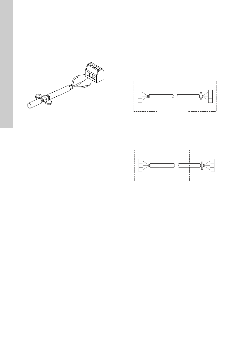
Use screened cables with a cross-sectional area of
minimum 0.5 mm
external on/off switch, digital inputs, setpoint and
sensor signals.
Connect the screens of the cables to the frame at
both ends with good connection. The screens must
be as close as possible to the terminals. See fig. 13.
2
and maximum 1.5 mm2 for the
7.8 Bus connection cable
7.8.1 New installations
For the bus connection, use a screened 3-core cable
with a cross-sectional area of minimum 0.5 mm
maximum 1.5 mm
If the motor is connected to a unit with a cable clamp
which is identical to the one on the motor, connect
2
.
the screen to this cable clamp.
If the unit has no cable clamp as shown in fig. 14,
leave the screen unconnected at this end.
2
and
Fig. 13 Stripped cable with screen and wire
Always tighten screws for frame connections
whether a cable is fitted or not.
The wires in the motor terminal box must be as short
as possible.
connections
TM02 1325 4402
Fig. 14 Connection with screened 3-core cable
7.8.2 Replacing a motor
If you use a a screened 2-core cable in the
installation, connect it as shown in fig. 15.
Fig. 15 Connection with screened 2-core cable
If you use a screened 3-core cable in the installation,
follow the instructions in section 7.8.1 New
installations.
TM05 3973 1812TM02 8842 0904
16
Page 17

8. Operating conditions
0
0
20
40
60
80
100
500 1000 1500 2000 2500
Altitude [m]
P2
[%]
8.1 Maximum number of starts and stops
The number of starts and stops via the power supply
must not exceed four times per hour.
When switched on via the power supply, the motor
starts after approximately 5 seconds.
If a higher number of starts and stops is desired, use
the input for external start/stop when
starting/stopping the motor.
When started via an external on/off switch, the motor
starts immediately.
8.2 Ambient temperature
8.2.1 Ambient temperature during storage and transportation
Minimum: -30 °C
Maximum: 60 °C.
8.2.2 Ambient temperature during operation
Minimum: -20 °C
Maximum: 50 °C.
The motor can operate with the rated power output
(P2) at 50 °C, but continuous operation at higher
temperatures reduces the expected product life. If
the motor is to operate at ambient temperatures
between 50 and 60 °C, select an oversized motor.
Contact Grundfos for further information.
8.3 Installation altitude
If the motor is installed above 2000 m, it
does not comply with the SELV/PELV
classification.
Installation altitude is the height above sea level of
the installation site.
Motors installed up to 1000 metres above sea level
can be loaded 100 %.
Motors installed more than 1000 metres above sea
level must not be fully loaded due to the low density
and consequent low cooling effect of the air. See fig.
16.
8.4 Humidity
Maximum humidity: 95 %.
If the humidity is constantly high and above 85 %,
open the drain holes in the drive-end flange. See
section 6.6 Drain holes.
8.5 Motor cooling
To ensure cooling of motor and electronics, observe
the following:
• Position the motor in such a way that adequate
cooling is ensured. See section 6.4 Ensuring
motor cooling.
• The temperature of the cooling air must not
exceed 50 °C.
• Keep cooling fins and fan blades clean.
English (GB)
Fig. 16 Derating of motor output power (P2) in
TM05 5243 3512
relation to altitude above sea level
17
Page 18

9. User interfaces
1
2
English (GB)
WARNING
Hot surface
Death or serious personal injury
- Only touch the buttons on the display as
the product may be very hot.
WARNING
Electric shock
Death or serious personal injury
- If the control panel is cracked or
perforated, replace it immediately.
Contact the nearest Grundfos sales
company.
You can make the motor settings by means of the
following user interfaces:
Control panels
• Basic control panel.
See section 9.1 Basic control panel.
• Standard control panel.
See section 9.2 Standard control panel.
• Advanced control panel.
See section 9.3 Advanced control panel
Remote controls
• Grundfos GO.
See section 9.4 Grundfos GO.
• Grundfos R100 remote control.
See section 9.5 R100 remote control.
If the power supply to the motor is switched off, the
motor settings are stored.
9.1 Basic control panel
Fig. 17 Basic control panel
Pos. Symbol Description
Grundfos Eye
1
2
9.1.1 Settings
Make all settings with Grundfos R100 or Grundfos
GO.
9.1.2 Resetting of alarms and warnings
You can reset a fault indication in one of the
following ways:
• Via the digital input if it has been set to "Alarm
resetting".
• Switch off the power supply until the indicator
lights are off.
• Switch the external start/stop input off and then
on again.
• With R100.
• With Grundfos GO.
Shows the operating status of
the motor.
See section 13. Grundfos Eye.
Enables radio communication
with Grundfos GO and other
MGE motors of the same type.
TM05 4847 2712
18
Page 19

9.2 Standard control panel
1
2
3
4
5
Stop
0
6
3
bar
H
Q
Fig. 18 Standard control panel
Pos. Symbol Description
Grundfos Eye
1
2-
3
4
5
Shows the operating status of
the motor.
See section 13. Grundfos Eye.
Light fields for indication of
setpoint.
Up and down. Changes the
setpoint.
Enables radio communication
with Grundfos GO and other
MGE motors of the same type.
Makes the motor ready for
operation or starts and stops
motor.
Start
If you press the button when
the motor is stopped, the
motor only starts if no other
functions with higher priority
have been enabled. See
section 12. Priority of settings.
Stop
If you press the button when
the motor is running, the motor
always stops. The "Stop" text
next to the button is on.
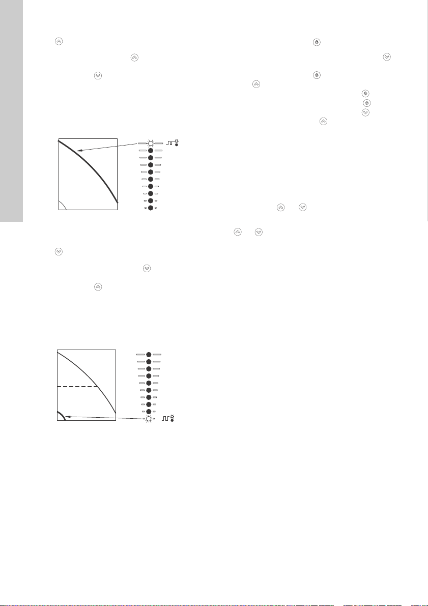
9.2.1 Setpoint setting
Set the desired setpoint of the motor by pressing
or . The green light fields on the control panel
indicate the setpoint set.
Motor in controlled-operation mode
The following example applies to a pump in an
application where a pressure sensor gives a
feedback to the pump. The sensor has been set
manually, and the pump does not automatically
register a connected sensor.
Figure 19 shows that the light fields 5 and 6 are
activated, indicating a desired setpoint of 3 bar with
a sensor measuring range from 0 to 6 bar. The
setting range is equal to the sensor measuring
range.
TM05 4848 3512
Fig. 19 Setpoint set to 3 bar, pressure-control
mode
Motor in uncontrolled-operation mode
In uncontrolled-operation mode, the motor output
lies between maximum and minimum speed. See fig.
20.
Fig. 20 Motor in uncontrolled-operation mode
English (GB)
TM05 4894 3512TM05 4895 2812
19
Page 20
Setting to maximum speed
H
Q
H
Q
English (GB)
continuously to change over to the
Press
maximum speed. The top light field flashes. When
the top light field is on, press
the light field starts flashing.
To go back, press
setpoint is indicated.
Example
The motor is set to maximum speed.
Figure 21 shows that the top light field is flashing,
indicating maximum speed.
Fig. 21 Maximum speed duty
Setting to minimum speed
Press
continuously to change over to the
minimum speed (bottom light field flashes). When
the bottom light field is on, press
until the light field starts flashing.
To go back, press continuously until the desired
setpoint is indicated.
Example
The motor is set to minimum speed.
Figure 22 shows that the bottom light field is
flashing, indicating minimum speed.
continuously until the desired
for 3 seconds until
for 3 seconds
9.2.2 Start/stop of motor
Stop the motor by pressing . When the motor is
stopped, the "Stop" text next to the button is on. You
can also stop the motor by continuously pressing
until none of the light fields are on.
Start the motor by pressing
pressing until the desired setpoint is indicated.
If you have stopped the motor by pressing , it can
only be given free to operation by pressing again.
If you have stopped the motor by pressing , it can
only be restarted by pressing .
You can also stop the motor with R100, Grundfos GO
or via a digital input set to "External stop". See
section 12. Priority of settings.
9.2.3 Resetting of alarms and warnings
You can reset a fault indication in one of the
following ways:
• Via the digital input if you have set it to "Alarm
resetting".
• Briefly press or
not change the setting of the motor.
TM05 4896 2812TM05 4897 2812
You cannot reset a fault indication by pressing
• Switch off the power supply until the indicator
lights are off.
• Switch the external start/stop input off and then
on again.
• With R100.
• With Grundfos GO.
if the buttons have been locked.
or
or by continuously
on the motor. This does
Fig. 22 Minimum speed duty
20
Page 21
9.3 Advanced control panel
1
2
3
4
5
6
The motors can be fitted with the advanced control
panel as an option.
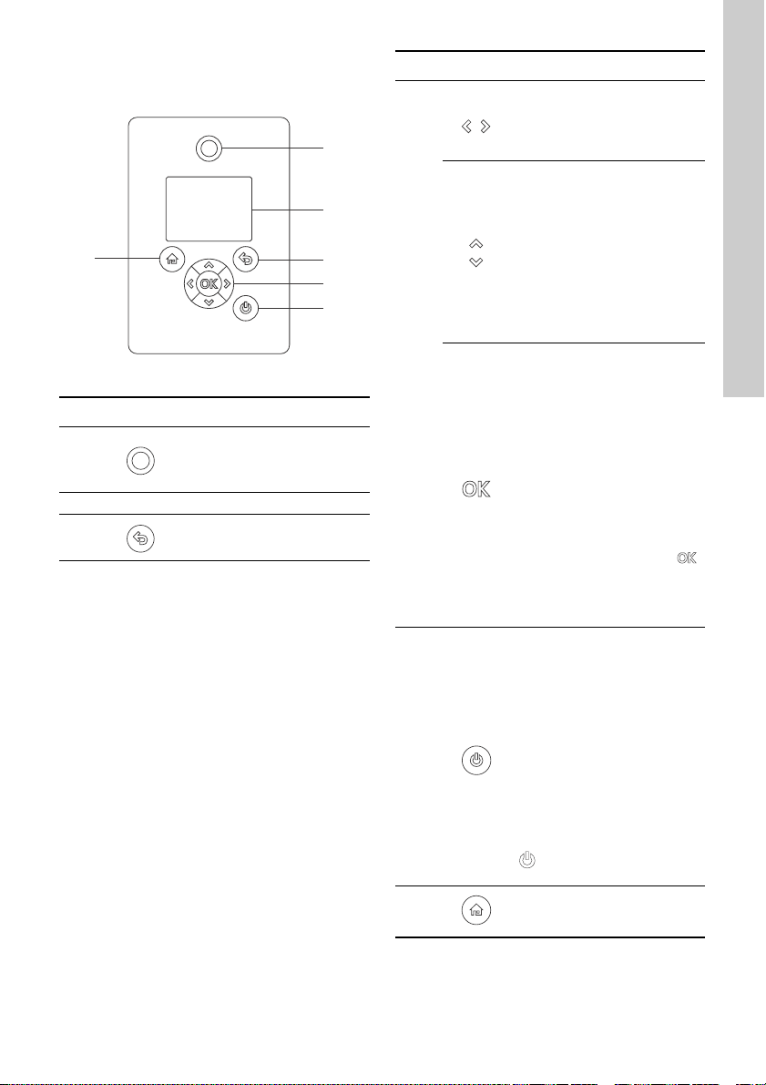
Fig. 23 Advanced control panel
Pos. Symbol Description
Grundfos Eye
1
2 - Graphical colour display.
3 Goes one step back.
Shows the operating status of
the motor.
See section 13. Grundfos Eye.
Pos. Symbol Description
TM05 4849 1013
4
5
Navigates between main
menus, displays and digits.
When you change the menu,
the display always shows the
top display of the new menu.
Navigates between submenus.
Changes value settings.
Note: If you have disabled the
possibility to make settings
with the ""Enable/disable
settings"" function, then you
can enable it again temporarily
by pressing these buttons
simultaneously for at least 5
seconds. See section
10.27 "Buttons on product"
(""Enable/disable settings"").
Saves changed values, resets
alarms and expands the value
field.
Enables radio communication
with Grundfos GO and other
products of the same type.
When you try to establish radio
communication between the
motor and Grundfos GO or
another motor, the green
indicator light in Grundfos Eye
flashes. A note also appears in
the controller display stating
that a wireless device wants to
connect to the motor. Press
on the motor control panel to
allow radio communication with
Grundfos GO and other
products of the same type.
Makes the motor ready for
operation or starts and stops
the motor.
Start
If you press the button when
the motor is stopped, the motor
starts if no other functions with
higher priority have been
enabled. See section
12. Priority of settings.
Stop
If you press the button when
the motor is running, the motor
always stops. When you stop
the motor via this button, the
icon appears in the bottom
of the display.
English (GB)
6 Goes to the ""Home"" menu.
21
Page 22

9.3.1 "Home" display
Setpoint
5.00 bar
Operaring mode
Normal
Actual controlled value
4.90 bar
Control mode
Const. pressure
Status Settings Assist
1 2 3 4
56789
Home
English (GB)
Fig. 24 Example of ""Home"" display
Pos. Symbol Description
""Home""
This menu shows up to four
user-defined parameters. You
1
2-
3-
4-
5
6
7
can select parameters shown
as shortcut icon , and when
pressing you go directly to
the "Settings" display for the
selected parameter.
""Status""
This menu shows the status of
the motor and system as well
as warnings and alarms.
""Settings""
This menu gives access to all
setting parameters. You can
make detailed settings of the
motor in this menu.
See section 10. Description of
functions.
""Assist""
This menu enables assisted
motor setup, provides a short
description of the control
modes and offers fault advice.
See section 10.38 ""Assist"".
Indicates that the motor has
been stopped via the
button.
Indicates that the motor is
functioning as a master in a
multimotor system.
Indicates that the motor is
functioning as slave in a
multimotor system.
Pos. Symbol Description
Indicates that the motor is
8
9
9.3.2 Startup guide
The motor incorporates a startup guide which is
started at the first startup. See section 10.35 ""Run
start-up guide"". After the startup guide, the main
menus appear in the display.
TM06 4516 2415
operating in a multimotor
system. See section
10.42 ""Setup of multi-pump
system"" (Multimotor).
Indicates that the possibility to
make settings has been
disabled for protective reasons.
See section 10.27 "Buttons on
product" (""Enable/disable
settings"").
22
Page 23

9.3.3 Menu overview for advanced control panel
Advanced control panel
"Home" MGE Multimotor system
●●
"Status" MGE Multimotor system
""Operating status"" ●●
""Operating mode, from"" ●●
""Control mode"" ●●
""Pump performance"" ●●
""Actual controlled value"" ●●
""Resulting setpoint"" ●●
""Speed"" ●●
""Acc. flow and specific energy"" ●●
""Power and energy consumption"" ●●
""Measured values"" ●●
""Analog input 1"" ●●
""Analog input 2"" ●●
""Analog input 3""
""Pt100/1000 input 1""
""Pt100/1000 input 2""
""Analog output""
1)
1)
1)
1)
●●
●●
●●
●●
""Warning and alarm"" ●●
""Actual warning or alarm"" ●●
""Warning log"" ●●
""Alarm log"" ●●
""Operating log"" ●●
""Operating hours"" ●●
""Fitted modules"" ●●
""Date and time"" ●●
""Product identification"" ●●
""Motor bearing monitoring"" ●●
""Multi-pump system"" ●
""System operating status"" ●
""System performance"" ●
""System input power and energy"" ●
""Pump 1, multi-pump system"" ●
""Pump 2, multi-pump system"" ●
""Pump 3, multi-pump system"" ●
""Pump 4, multi-pump system"" ●
1)
Only available if an advanced functional module, type FM 300, is fitted.
English (GB)
23
Page 24

English (GB)
"Settings" MGE
Advanced control panel
Multimotor
system
Section Page
""Setpoint"" ●●10.1 ""Setpoint"" 32
""Operating mode"" ●●10.2 ""Operating mode"" 32
""Set manual speed"" ●●10.3 ""Set manual speed"" 32
""Control mode"" ●●10.4 "Control mode" 32
""Analog inputs"" ●●
""Analog input 1, setup"" ●●
""Analog input 2, setup"" ●●
""Analog input 3, setup""
""Pt100/1000 inputs""
1)
1)
●●
●●
10.5 ""Analog inputs"" 32
10.6 ""Pt100/1000 inputs"" 33""Pt100/1000 input 1, setup"" ●●
""Pt100/1000 input 2, setup"" ●●
""Digital inputs"" ●●
10.7 "Digital inputs" 34""Digital input 1, setup"" ●●
""Digital input 2, setup""
1)
●●
""Digital inputs/outputs"" ●●
10.8 ""Digital inputs/outputs"" 35""Digital input/output 3, setup"" ●●
""Digital input/output 4, setup""
1)
●●
""Relay outputs"" ●●
10.9 "Signal relay" (""Relay
""Relay output 2"" ●●
""Analog output""
1)
●●
outputs"")
10.10 ""Analog output"" 36""Output signal"" ●●
""Function of analog output"" ●●
""Controller settings"" ●●
10.11 "Controller" (""Controller
settings"")
""Operating range"" ●●10.12 ""Operating range"" 37
""Setpoint influence"" ●●
""Ext. setpoint infl."" ●●10.13 ""External setpoint function"" 37
""Predefined setpoints""
1)
●●10.14 "Predefined setpoints" 40
""Monitoring functions"" ●●
""Motor bearing monitoring"" ●●10.20 ""Motor bearing monitoring"" 42
""Motor bearing maintenance"" ●●
"Bearings replaced" (""Motor
bearing maintenance"")
""Limit-exceeded function"" ●●10.15 ""Limit-exceeded function"" 41
1)
Only available if an advanced functional module, type FM 300, is fitted.
Continued on page 25.
36""Relay output 1"" ●●
37
43
24
Page 25

Continued from page 24.
Advanced control panel
"Settings" CME
""Special functions"" ●●
""Ramps"" ●●10.16 "Ramps" 42
""Standstill heating"" ●●10.19 ""Standstill heating"" 42
""Communication"" ●●
""Pump number"" ●●
""Enable/disable radio comm."" ●●
""General settings"" ●●
""Language"" ●●10.24 ""Language"" 43
""Set date and time"" ●●
""Units"" ●●
""Enable/disable settings"" ●●
""Delete history"" ●●10.28 ""Delete history"" 44
""Define Home display"" ●●10.29 ""Define Home display"" 44
""Display settings"" ●●10.30 ""Display settings"" 44
""Store actual settings"" ●●
""Recall stored settings"" ●●
""Run start-up guide"" ●●10.35 ""Run start-up guide"" 45
1)
Only available if an advanced functional module, type FM 300, is fitted.
Multimotor
system
Section Page
10.22 "Number" (""Pump
number"")
10.23 "Radio communication"
(""Enable/disable radio comm."")
10.25 "Date and time" (""Set date
and time"")
10.26 "Unit configuration"
(""Units"")
10.27 "Buttons on product"
(""Enable/disable settings"")
10.31 "Store settings" (""Store
actual settings"")
10.32 "Recall settings" (""Recall
stored settings"")
English (GB)
43
43
43
43
43
44
44
"Assist" MGE
""Assisted pump setup"" ●●
""Setup, analog input"" ●●10.40 ""Setup, analog input"" 46
""Setting of date and time"" ●●
""Setup of multi-pump system"" ●●
""Description of control mode"" ●●
""Assisted fault advice"" ●●10.44 ""Assisted fault advice"" 49
Multimotor
system
Section Page
10.39 ""Assisted pump setup""
(Assisted motor setup)
10.25 "Date and time" (""Set date
and time"")
10.42 ""Setup of multi-pump
system"" (Multimotor)
10.43 ""Description of control
mode""
45
43
46
49
25
Page 26

9.4 Grundfos GO
+
+
1
2
English (GB)
The motor is designed for wireless radio or infrared
communication with Grundfos GO.
Grundfos GO enables setting of functions and gives
access to status overviews, technical product
information and actual operating parameters.
Grundfos GO offers the following mobile interfaces
(MI). See fig. 25.
Fig. 25 Grundfos GO communicating with the
Pos. Description
motor via radio or infrared connection,
IR
Grundfos MI 204:
Add-on module enabling radio or infrared
communication. You can use MI 204 in
conjunction with an Apple iPhone or iPod
1
with Lightning connector, e.g. fifth
generation or later iPhone or iPod.
MI 204 is also available together with an
Apple iPod touch and a cover.
Grundfos MI 301:
Separate module enabling radio or infrared
2
communication. You can use the module in
conjunction with an Android or iOS-based
smart device with Bluetooth connection.
9.4.1 Communication
When Grundfos GO initiates communication with the
motor, the indicator light in the middle of Grundfos
Eye flashes green. See section 13. Grundfos E ye.
On motors fitted with an advanced control panel a
text appears in the display saying that a wireless
device is trying to establish connection. Press on
the motor in order to establish connection with
Grundfos GO or press
Establish communication using one of these
communication types:
• radio communication
• infrared communication.
Radio communication
Radio communication can take place at distances up
to 30 metres. The first time Grundfos GO
communicates with the motor, you must enable
communication by pressing or on the motor
control panel. Later when communication takes
place, the motor is recognized by Grundfos GO and
you can select the motor from the "List" menu.
Infrared communication
When communicating via infrared light, Grundfos GO
must be pointed at the motor control panel.
TM06 6256 0916
to reject connection.
26
Page 27

9.4.2 Menu overview for Grundfos GO
Dashboard MGE Multimotor system
●●
Status MGE Multimotor system
"System mode"
2)
●
"Resulting setpoint" ●
"Resulting system setpoint"
2)
●
"Actual controlled value" ●●
"Motor speed" ●
"Power consumption" ●
"Power consumption, system"
2)
●
"Energy consumption" ●
"Energy consumption, system"
"Actual flow rate, specific energy"
"2)
2)
●●
●
"Operating hours" ●
"Motor current" ●
"Number of starts" ●
"Operating hours, system"
"Pt100/1000 input 1"
"Pt100/1000 input 2"
2)
1)
1)
●
●
●
"Analog output" ●
"Analog input 1" ●
"Analog input 2" ●
"Analog input 3" ●
"Digital input 1" ●
"Digital input 2" ●
"Digital in/output 3" ●
"Digital in/output 4" ●
"Fitted modules" ●
"Pump 1"
"Pump 2"
"Pump 3"
"Pump 4"
1)
Only available if an advanced functional module, type FM 300, is fitted.
2)
Only available if Grundfos GO is connected to a multimotor system.
2)
2)
2)
2)
●
●
●
●
English (GB)
27
Page 28

English (GB)
Settings MGE
Multimotor
system
Section Page
"Setpoint" ●●10.1 ""Setpoint"" 32
"Operating mode" ●●10.2 ""Operating mode"" 32
"Control mode" ●●10.4 "Control mode" 32
"Pipe-filling function" ●●10.16 "Ramps" 42
"Buttons on product" ●
"Controller" ●●
10.27 "Buttons on product"
(""Enable/disable settings"")
10.11 "Controller" (""Controller
settings"")
"Operating range" ●●10.12 ""Operating range"" 37
"Ramps" ● 10.16 "Ramps" 42
"Number" ● 10.22 "Number" (""Pump number"") 43
"Radio communication" ●
10.23 "Radio communication"
(""Enable/disable radio comm."")
"Analog input 1" ●
10.5 ""Analog inputs"" 32"Analog input 2" ●
"Analog input 3"
"Pt100/1000 input 1"
"Pt100/1000 input 2"
"Digital input 1" ●
"Digital input 2"
"Digital in/output 3" ●
"Digital in/output 4"
1)
1)
1)
1)
1)
●
●
●
●
●
10.6 ""Pt100/1000 inputs"" 33
10.7 "Digital inputs" 34
10.8 ""Digital inputs/outputs"" 35
"Predefined setpoint" ●●10.14 "Predefined setpoints" 40
1) + 2)
1)
● 10.10 ""Analog output"" 36
● 10.13 ""External setpoint function"" 37
10.9 "Signal relay" (""Relay outputs"") 36
10.15 ""Limit-exceeded function"" 41
●
●
10.42 ""Setup of multi-pump system""
(Multimotor)
"Analog output"
"External setpoint
function"
"Signal relay 1" ●
"Signal relay 2" ●
"Limit 1 exceeded" ●●
"Limit 2 exceeded" ●●
"Alternating operation,
2)
time"
"Time for pump
changeover"
1)
Only available if an advanced functional module, type FM 300, is fitted.
Continued on page 29.
43
37
43
46
28
Page 29

Continued from page 29.
Settings MGE
Multimotor
system
Section Page
"Standstill heating" ● 10.19 ""Standstill heating"" 42
"Motor bearing
monitoring"
● 10.20 ""Motor bearing monitoring"" 42
"Service" ● 10.21 "Service" 43
"Date and time"
1)
"Store settings" ●
"Recall settings" ●
●
10.25 "Date and time" (""Set date and
time"")
10.31 "Store settings" (""Store actual
settings"")
10.32 "Recall settings" (""Recall stored
settings"")
"Undo" ●●10.32.1 "Undo" 44
"Pump name" ●●10.33 "Pump name" (motor name) 44
"Connection code" ●●10.34 "Connection code" 44
"Unit configuration" ● 10.26 "Unit configuration" (""Units"") 43
1)
Only available if an advanced functional module, type FM 300, is fitted.
2)
Only available if Grundfos GO is connected to a multimotor system.
English (GB)
43
44
44
Alarms and warnings MGE
Multimotor
system
Section Page
"Alarm log" ●●10.36 ""Alarm log"" 45
"Warning log" ●●10.37 ""Warning log"" 45
"Reset alarm button" ●●
Assist MGE
"Assisted pump setup" ●
Multimotor
system
Section Page
10.39 ""Assisted pump setup""
(Assisted motor setup)
"Assisted fault advice" ●●10.44 ""Assisted fault advice"" 49
"Multipump setup" ●●
10.42 ""Setup of multi-pump system""
(Multimotor)
45
46
29
Page 30

9.5 R100 remote control
English (GB)
The motor is designed for wireless communication
with the Grundfos R100 remote control.
Fig. 26 R100 communicating with the motor via
9.5.1 Menu overview for R100
General
"Switch off R100"
"Return to start"
"Delete all changes"
"Store settings"
"Call up settings"
"Store status data"
"Call up status data"
infrared light
During communication, point R100 at the control
panel. When R100 communicates with the motor, the
indicator light in the middle of Grundfos Eye flashes
green. See page 51.
R100 offers additional possibilities of setting and
status displays for the motor.
The displays are divided into four parallel menus:
"0. GENERAL". See the operating instructions for
R100.
"1. OPERATION"
"2. STATUS"
"3. INSTALLATION."
See section 9.5.1 Menu overvie w for R100.
TM06 4927 3115
It may be necessary to update R100 to access the
new menus.
R100 remote control
Operation Section Page
"Setpoint" 10.1 ""Setpoint"" 32
"Operating mode" 10.2 ""Operating mode"" 32
"Manual speed" 10.3 ""Set manual speed"" 32
"Alarm" 10.36 ""Alarm log"" 45
"Warning" 10.37""Warning log"" 45
"Alarm log 1 to 5"
"Warning log 1 to 5"
30
Page 31

Status
"Actual setpoint and external setpoint"
"Operating mode"
"Actual controlled value"
"Analog input 1, 2 and 3"
"Pt100/1000 input 1 and 2"
"Speed"
"Power input and power consumption"
"Operating hours"
"Replace motor bearings"
"Motor current"
R100 remote control
Installation Section Page
"Control mode" 10.4 "Control mode" 32
"Controller" 10.11 "Controller" (""Controller settings"") 37
"Signal relay 1 and 2" 10.9 "Signal relay" (""Relay outputs"") 36
"Buttons on product"
"Number" 10.22 "Number" (""Pump number"") 43
"Radio communication"
"Digital input 1 and 2, Function" 10.7 "Digital inputs" 34
"Digital input/output 3 and 4, State"
"Digital input/output 3 and 4, Function"
"Analog input 1, 2 and 3, Function"
"Analog input 1, 2 and 3"
"Pt100/1000 input 1 and 2, Function"
"Pt100/1000 input 1 and 2, Measured parameter"
"External setpoint function" 10.13 ""External setpoint function"" 37
"Operating range" 10.12 ""Operating range"" 37
"Ramps" 10.16 "Ramps" 42
"Direction of rotation" 10.17 "Direction of rotation" 42
"Skip band 1"
"Skip band 2"
"Motor bearing monitoring" 10.20 ""Motor bearing monitoring"" 42
"Motor bearings" 10.21 "Service" 43
"Standstill heating" 10.19 ""Standstill heating"" 42
10.27 "Buttons on product" (""Enable/disable
settings"")
10.23 "Radio communicatio n"
(""Enable/disable radio comm."")
10.8 ""Digital inputs/outputs"" 35
10.5 ""Analog inputs"" 32"Analog input 1, 2 and 3, Measured parameter"
10.6 ""Pt100/1000 inputs"" 33
10.18 "Skip band" 42
43
43
English (GB)
31
Page 32

10. Description of functions
H
Q
English (GB)
10.1 ""Setpoint""
You can set the setpoint for all control modes when
you have selected the desired control mode. See
section 10.4 "Control mode".
10.2 ""Operating mode""
Possible operating modes:
• ""Normal""
The motor runs according to the selected control
mode.
• ""Stop""
The motor stops.
•""Min.""
The motor runs at minimum speed.
•""Max.""
The motor runs at maximum speed.
• ""Manual""
The motor is operating at a manually set speed.
In ""Manual"" the setpoint via bus is overruled.
See section 10.3 ""Set manual speed"".
10.3 ""Set manual speed""
This menu is only available in the advanced control
panel. With Grundfos GO, you set the speed via the
""Setpoint"" menu.
You can set the motor speed in % of the maximum
speed. When you have set the operating mode to
""Manual"", the motor runs at the set speed.
10.4 "Control mode"
Possible control modes:
• "Constant other value"
• "Constant curve".
10.4.1 "Constant other value"
Any other value is kept constant.
Use this control mode if you wish to control a value
which is not available in the ""Control mode"" menu.
Connect a sensor measuring the controlled value to
one of the analog inputs of the pump. The controlled
value is shown in percentage of sensor range.
10.4.2 "Constant curve" (Constant speed)
You can set the motor to operate at a constant
speed. See fig. 27.
The desired speed can be set in % of maximum
speed in the range from 13 to 100 %.
Fig. 27 Constant speed
""Controller settings""
See section 10.11 "Controller" (""Controller
settings"").
10.5 ""Analog inputs""
Available inputs depend on the functional module
fitted in the motor.
Function (terminal)
Setting the analog
input 1 (4)
Setting the analog
input 2 (7)
Setting the analog
input 3 (14)
* See section 15. Identification of functional
module.
You can set the analog inputs via the ""Setup, analog
input"" menu. See section 10.40 ""Setup, analo g
input"".
If you make the manual setting via Grundfos GO, you
need to enter the menu for the analog input under
the ""Settings"" menu.
Function
You can set the analog inputs to these functions:
• ""Not active""
• ""Feedback sensor""
The sensor is used for the selected control mode.
• ""Ext. setpoint infl.""
See section 10.13 ""External setpoint function"".
• ""Other function"".
FM 200*
(standard)
●●
●●
- ●
FM 300*
(advanced)
TM05 7957 1713
32
Page 33

Measured parameter
PT PT PTPTTT
TT
TT
Q
Q
DPT
DPT DPT
LT LT
DPT DTT
1
5
24
910
7
12
816 15
313 6 14
11
Select one of the parameters listed below, i.e. the
parameter to be measured in the system by the
sensor connected to the analog input. See fig. 28.
Fig. 28 Overview of sensor locations
Sensor function/measured
parameter
Pos.
Inlet pressure 1
Differential pressure, inlet 2
Outlet pressure 3
Differential pressure, outlet 4
Differential pressure, pump 5
Pressure 1, external 6
Pressure 2, external 7
Differential pressure, external 8
Storage tank level 9
Feed tank level 10
Pump flow 11
Flow, external 12
Liquid temperature 13
Temperature 1 14
Temperature 2 15
Differential temperature, external 16
Ambient temperature Not shown
Other parameter Not shown
"Unit"
"Electrical signal"
Select signal type:
• 0.5 - 3.5 V
•0-5 V
• 0-10 V
• 0-20 mA
• 4-20 mA.
Sensor range, minimum value
Set the minimum value of the connected sensor.
Sensor range, maximum value
Set the maximum value of the connected sensor.
10.6 ""Pt100/1000 inputs""
Available inputs depend on the functional module
fitted in the motor.
TM06 2328 3914
Function (terminal)
Setting the Pt100/1000
input 1 (17, 18)
Setting the Pt100/1000
input 2 (18, 19)
* See section 15. Identification of functional
module.
In order to set the Pt100/1000 input for a feedback
sensor, we recommend that you do this via the
""Assisted pump setup"" menu. See section
10.39 ""Assisted pump setup"" (Assisted motor
setup).
If you wish to set a Pt100/1000 input for other
purposes, you can do this manually.
Function
The Pt100/1000 inputs can be set to these functions:
• ""Not active""
• ""Feedback sensor""
The sensor is used for the selected control mode.
• ""Ext. setpoint infl.""
See section 10.13 ""External setpoint function"".
• ""Other function"".
FM 200*
(standard)
- ●
- ●
(advanced)
English (GB)
FM 300*
Parameter Possible units
Pressure "bar", "m", "kPa", "psi", "ft"
Level m, ft, in
Pump flow m
Liquid temperature °C, °F
3
/h, l/s, yd3/h, gpm
Other parameter %
33
Page 34
Measured parameter
TT
TT
TT
3
12
T input
T input > T1 + T2 T input < T1 + T2
T1 T2
T1 T2
T1 T1 T2T2
T1
T1
T input
T2
T input > T1 + T2
T input < T1 + T2
Mode C
Mode B
Mode A
Digital
input
English (GB)
Select one of the parameters listed below, i.e. the
parameter to be measured in the system by the
Pt100/1000 sensor connected to the Pt100/1000
input. See fig. 29.
Fig. 29 Overview of Pt100/1000 sensor
locations
Parameter Pos.
Liquid temperature 1
Temperature 1 2
Temperature 2 3
Ambient temperature Not shown
Measuring range
-50 - +204 °C.
10.7 "Digital inputs"
Available inputs depend on the functional module
fitted in the motor.
Function (terminal)
Setting the digital
input 1 (2, 6)
Setting the digital
input 2 (1, 9)
* See section 15. Identification of functional
module.
To set a digital input, make the settings below.
Function
Select one of these functions:
• ""Not active""
When set to ""Not active"", the input has no
function.
• ""External stop""
When the input is deactivated (open circuit), the
motor stops.
• ""Min."" (minimum speed)
When the input is activated, the motor runs at the
set minimum speed.
• ""Max."" (maximum speed)
When the input is activated, the motor runs at the
set maximum speed.
• ""External fault" "
When the input is activated, a timer is started. If
the input is activated for more than 5 seconds,
the motor is stopped and a fault is indicated. The
function depends on input from external
equipment.
34
FM 200*
(standard)
●●
- ●
FM 300*
(advanced)
• ""Alarm resetting""
When the input is activated, a possible fault
indication is reset.
• Reverse rotation
This function reverses the direction of rotation of
the motor.
• "Predefined setpoint digit 1"
Applies only to digital input 2.
When digital inputs are set to predefined
setpoint, the pump operates according to a
setpoint based on the combination of the
TM06 4012 1515
activated digital inputs. See section
10.14 "Predefined setpoints".
The priority of the selected functions in relation to
each other appears from section 12. Priority of
settings.
A stop command always has the highest priority.
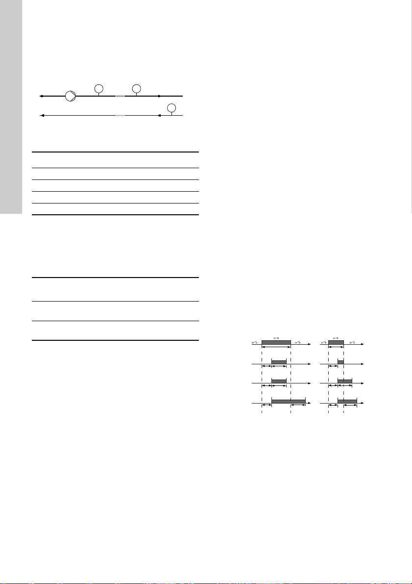
Activation delay
Select the activation delay (T1).
It is the time between the digital signal and the
activation of the selected function.
Range: 0-6000 seconds.
Duration timer mode
Select the mode. See fig. 30.
• ""Not active""
• active with interrupt (mode A)
• active without interrupt (mode B)
• active with after-run (mode C).
Select the duration time (T2).
It is the time which, together with the mode,
determines how long the selected function is active.
Range: 0-15,000 seconds.
Fig. 30 Duration timer functions of digital inputs
TM06 4949 3415
Page 35

10.8 ""Digital inputs/outputs""
+ 24V
DO 3/4
External
controlle
r
T input
T input > T1 + T2 T input < T1 + T2
T1 T2
T1 T2
T1 T1 T2T2
T1
T1
T input
T2
Mode C
Mode B
Mode A
Digital
input
T input > T1 + T2
T input < T1 + T2
Available inputs and outputs depend on the
functional module fitted in the motor. See section
15. Identification of functional module.
You can select if the interface is to be used as input
or output. The output is an open collector and you
can connect it to e.g. an external relay or controller
such as a PLC etc.
Fig. 31 Example of configurable digital
To set a digital input/output, make the settings below.
Mode
You can set the digital input/output 3 and 4 to act as
digital input or digital output.
Function
You can set the digital input/output 3 and 4 to the
functions stated in the tables below. See also
sections 10.7 "Digital inputs" and 10.9 "Signal relay"
(""Relay outputs"").
Possible functions, digital input/output 3
"Function if input" "Function if output"
• ""Not active""
• ""External stop""
•""Min.""
•""Max.""
• ""External fault""
• ""Alarm resetting""
• Reverse rotation
• ""Predefined
Possible functions, digital input/output 4
inputs/outputs
• ""Not active""
• ""Ready""
•""Alarm""
• ""Operation""
• ""Warning""
• ""Limit 1 exceeded""
• ""Limit 2 exceeded""
setpoint digit 2""
Activation delay (only for input)
Select the activation delay (T1).
It is the time between the digital signal and the
activation of the selected function.
Range: 0-6000 seconds.
Duration timer mode (only for input)
Select the duration timer mode. See fig. 30.
• ""Not active""
• active with interrupt (mode A)
• active without interrupt (mode B)
• active with after-run (mode C)
Select the duration time (T2).
It is the time which, together with the mode,
determines how long the selected function is active.
TM06 4463 2315
Range: 0-15,000 seconds.
Fig. 32 Duration timer function of digital inputs
English (GB)
TM06 4949 3415
"Function if input" "Function if output"
• ""Not active""
• ""External stop""
•""Min.""
•""Max.""
• ""External fault""
• ""Alarm resetting""
• Reverse rotation
• ""Predefined
setpoint digit 3""
• ""Not active""
• ""Ready""
• ""Alarm""
• ""Operation""
• ""Warning""
• ""Limit 1 exceeded""
• ""Limit 2 exceeded""
35
Page 36

10.9 "Signal relay" (""Relay outputs"")
English (GB)
The motor incorporates two signal relays for
potential-free signalling. See section 20. Signal
relays.
Function
You can configure the signal relays to be activated
by one of the following incidents:
• ""Not active""
• ""Ready""
The motor can be running or is ready to run and
no alarms are present.
• ""Alarm""
There is an active alarm and the motor is
stopped.
• "Operating" (""Operation"")
"Operating" equals "Running" but the motor is
still in operation when the motor is stopped.
• "Running" (""Pump running"")
The motor is running.
• ""Warning""
There is an active warning.
• ""Limit 1 exceeded""
When this function is activated, the signal relay is
activated. See section 10.15 ""Limit-exceeded
function"".
• ""Limit 2 exceeded""
When this function is activated, the signal relay is
activated. See section 10.15 ""Limit-exceeded
function"".
• "External fan control" (""Control of external fan"").
When you select this function, the relay is
activated if the internal temperature of the motor
electronics reach a preset limit value.
10.10 ""Analog output""
Whether the analog output is available or not,
depends on the functional module fitted in the motor.
See section 15. Identification of functional module.
The analog output enables the reading of certain
operating data to external control systems.
To set the analog output, make the settings below.
""Output signal""
• 0-10 V
• 0-20 mA
• 4-20 mA.
""Function of analog output""
• ""Actual speed""
Signal
range
0-10 V 0 V 5 V 10 V
0-20 mA 0 mA 10 mA 20 mA
4-20 mA 4 mA 12 mA 20 mA
The reading is a percentage of the rated speed.
• ""Actual value""
Signal
range
0-10 V 0 V 10 V
0-20 mA 0 mA 20 mA
4-20 mA 4 mA 20 mA
The reading is a percentage of the range between
minimum and maximum value.
• ""Resulting setpoint""
Signal
range
0-10 V 0 V 10 V
0-20 mA 0 mA 20 mA
4-20 mA 4 mA 20 mA
The reading is a percentage of the external setpoint
range.
• "Motor load"
Signal
range
0-10 V 0 V 5 V 10 V
0-20 mA 0 mA 10 mA 20 mA
4-20 mA 4 mA 12 mA 20 mA
"Actual speed"
[%]
0 100 200
Sensor value
Minimum Maximum
"Resulting setpoint"
[%]
0 100
"Motor load"
[%]
0 100 200
36
Page 37

The reading is a percentage of the range between 0
Fixed maximum speed
User-set maximum
speed
"Operating range"
User-set minimum
speed
Fixed minimum speed
24 %
13 %
0 %
67 %
100 %
100
0
100 %
0
1.2
2
0
3.5 V0.5
5 V0
10 V0
20 mA0
20 mA4
Actual input
signal (60 %)
External
setpoint
signal
Setpoint
Sensor
max.
Sensor
min.
Actual
setpoint
and 200 % of the maximum permissible load at the
actual speed.
• ""Motor current""
"Motor current"
Signal
range
0 100 200
[%]
0-10 V 0 V 5 V 10 V
0-20 mA 0 mA 10 mA 20 mA
4-20 mA 4 mA 12 mA 20 mA
The reading is a percentage of the range between 0
% and 200 % of the rated current.
• ""Limit 1 exceeded"" and ""Limit 2 exceeded""
10.12 ""Operating range""
Set the operating range as follows:
• Set the minimum speed within the range from
fixed minimum speed to user-set maximum
speed.
• Set the maximum speed within the range from
user-set minimum speed to fixed maximum
speed.
The range between the user-set minimum and
maximum speeds is the operating range. See fig. 33.
English (GB)
Signal
range
"Limit-exceeded function"
Output not
active
0-10 V 0 V 10 V
0-20 mA 0 mA 20 mA
4-20 mA 4 mA 20 mA
This function is typically used for monitoring of
secondary parameters in the system. If the limit is
exceeded, an output, a warning or an alarm is
activated.
10.11 "Controller" (""Controller settings"")
The gain (Kp) and integral time (Ti) are preset from
factory. However, if the factory setting is not the
optimum setting, you can change the gain and the
integral time:
• Set the gain (Kp) within the range from 0.1 to 20.
• Set the integral-action time (Ti) within the range
from 0.1 to 3600 seconds. If you select 3600
seconds, the controller functions as a P
controller.
Furthermore, you can set the controller to inverse
control.
This means that if you increase the setpoint, the
speed is reduced. In the case of inverse control, set
the gain (Kp) within the range from -0.1 to -20.
Output active
Fig. 33 Example of minimum and maximum
settings
10.13 ""External setpoint function""
You can influence the setpoint by an external signal,
via one of the analog inputs or, if an advanced
functional module, type FM 300, is fitted, via one of
the Pt100/1000 inputs.
Before you can enable the function, you
must set one of the analog inputs or
Pt100/1000 inputs to ""External setpoint
function"".
See sections 10.5 ""Analog inputs"" and
10.6 ""Pt100/1000 inputs"".
[bar]
TM00 6785 5095
Fig. 34 Example of setpoint influence with
sensor feedback
-50 204 C
TM06 4165 1615
37
Page 38

Example with constant curve with linear
100
0
100 %
0
3.5 V0.5
5 V0
10 V0
20 mA0
20 mA4
-50 204 C
25
61
85
External
setpoint
signal
Speed [%]
Fixed
maximum
speed
Actual
input signal
(60 %)
User-set
minimum
speed
Setpoint
Actual
setpoint
100
0
100 %0
3.5 V0.5
5 V0
10 V0
20 mA0
20 mA4
-50 204 C
"Setpoint influence" [%]
External
input
100
0
20 100 %0
3.5 V0.5
5 V0
10 V0
20 mA0
20 mA4
-50 204 C
"Setpoint influence" [%]
External
input
"Normal"
"Min." or
"Stop"
100
0
100 %0
3.5 V0.5
5 V0
10 V0
20 mA0
20 mA4
-50 204 C
"Setpoint influence" [%]
External
input
English (GB)
influence/function
Actual setpoint: actual input signal x (setpoint user-set minimum speed) + user-set minimum
speed.
At a user-set minimum speed of 25 %, and a setpoint
of 85 % and an external setpoint of 60 %, the actual
setpoint is 0.60 x (85 - 25) + 25 = 61 %. See fig. 35.
Fig. 35 Example of setpoint influence with
constant curve
10.13.1 "Setpoint influence" functions
You can select these functions:
• ""Not active""
When set to ""Not active"", the setpoint is not
influenced from any external function.
• ""Linear function""
The setpoint is influenced linearly from 0 to 100
%. See fig. 36.
• ""Linear with Stop"" and ""Inverse with Min.""
– ""Inverse with Stop""
In the input signal range from 20 to 100 %, the
setpoint is influenced linearly.
If the input signal is below 10 %, the motor
changes to operating mode ""Stop"".
If the input signal is increased above 15 %, the
operating mode is changed back to ""Normal"".
See fig. 37.
– ""Inverse with Min.""
In the input signal range from 20 to 100 %, the
setpoint is influenced linearly.
If the input signal is below 10 %, the motor
changes to operating mode ""Min."".
If the input signal is increased above 15 %, the
operating mode is changed back to ""Normal"".
See fig. 37.
TM06 4525 2515TM06 4166 1615
Fig. 37 ""Linear with Stop"" and ""Inverse with
• ""Inverse function""
Min.""
The setpoint is influenced inversely from 0 to 100
%. See fig. 38.
TM06 4167 1615TM06 4168 1615
Fig. 36 ""Linear function""
38
Fig. 38 ""Inverse function""
Page 39
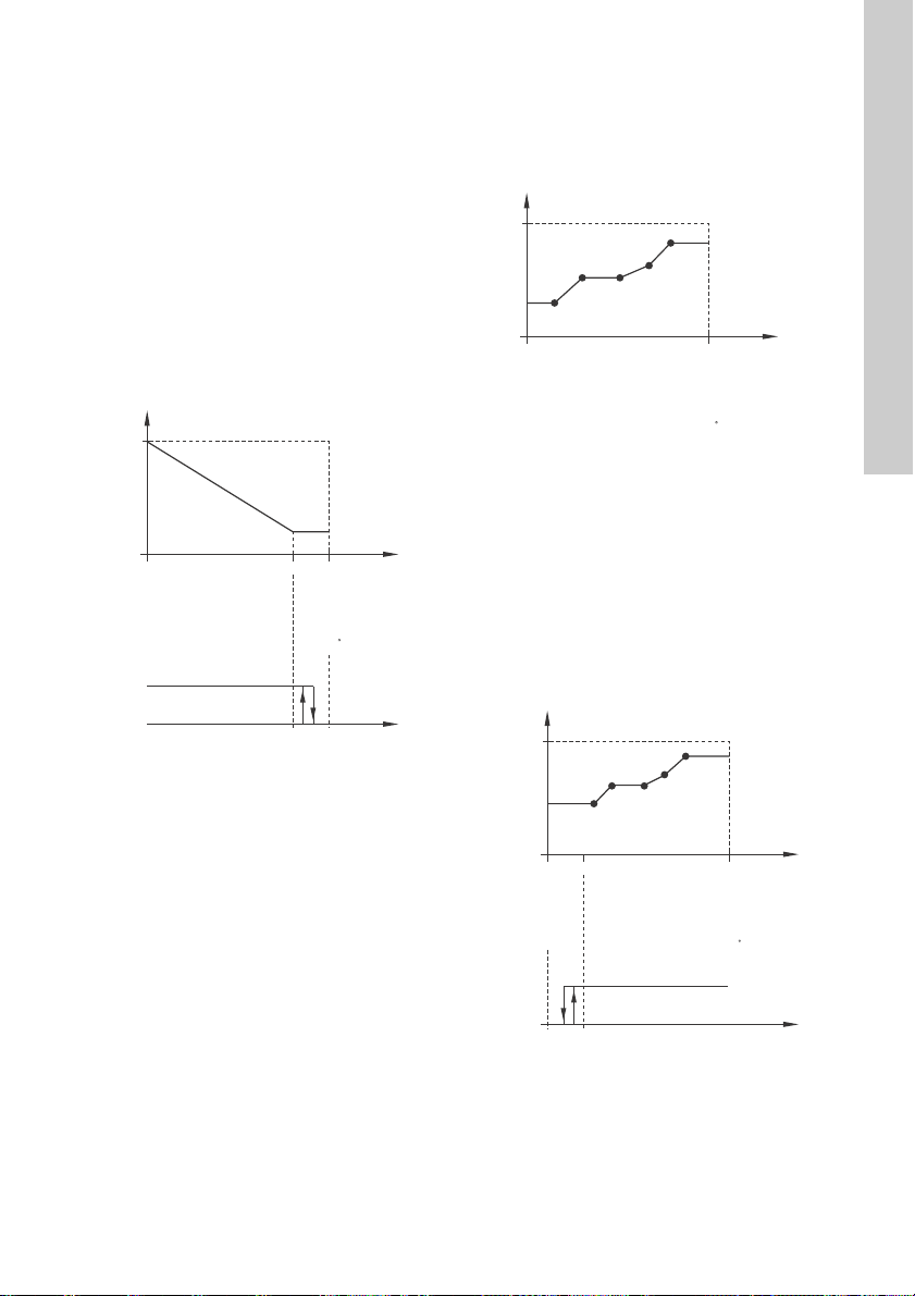
• ""Inverse with Stop"" and ""Inverse with Min.""
100
0
80
0
0.5
0
0
0
4
-50
100 %
3.5 V
5 V
10 V
20 mA
20 mA
204 C
Setpoint influence [%]
External
input
"Normal"
"Min." or
"Stop"
100
0
100 %0
3.5 V0.5
5 V0
10 V0
20 mA0
20 mA4
"Setpoint influence" [%]
External
input
100
0
20
0
0.5
0
0
0
4
-50
100 %
3.5 V
5 V
10 V
20 mA
20 mA
204 C
"Setpoint influence" [%]
External
input
"Normal"
"Min." or
"Stop"
– ""Inverse with Stop""
In the input signal range from 0 to 80 %, the
setpoint is influenced inversely.
If the input signal is above 90 %, the motor
changes to operating mode ""Stop"".
If the input signal is reduced below 85 %, the
operating mode is changed back to ""Normal"".
See fig. 39.
– ""Inverse with Min.""
In the input signal range from 0 to 80 %, the
setpoint is influenced inversely.
If the input signal is above 90 %, the motor
changes to operating mode ""Min."".
If the input signal is reduced below 85 %, the
operating mode is changed back to ""Normal"".
See fig. 39.
• ""Influence table""
The setpoint is influenced by a curve made out of
two to eight points. There is a straight line
between the points and a horizontal line before
the first point and after the last point.
English (GB)
Fig. 39 ""Inverse with Stop"" and ""Inverse with
Min.""
-50 204 C
Fig. 40 ""Influence table"" (example with five
points)
• ""Influence table with Stop at Min.""
The setpoint is influenced by a curve made out of
two to eight points. There is a straight line
between the points and a horizontal line before
the first point and after the last point. If the input
signal is below 10 %, the motor changes to
operating mode ""Stop"".
If the input signal is increased above 15 %, the
operating mode is changed back to ""Normal"".
See fig. 41.
TM06 4169 1615
Fig. 41 ""Influence table with Stop at Min.""
(example with five points)
TM06 4170 1615TM06 4171 1615
39
Page 40

• ""Influence table with Stop at Max.""
100
0
800
0.5
0
0
0
4
-50
100 %
3.5 V
5 V
10 V
20 mA
20 mA
204 C
"Setpoint influence" [%]
External
input
"Normal"
"Min." or
"Stop"
0
1
2
3
4
5
6
7
Digital input 4
Setpoint 1
Setpoint 2
Setpoint 3
Setpoint 4
Setpoint 5
Setpoint 6
Setpoint 7
Digital input 3
Digital input 2
Actual setpoint
Stop
Normal
setpoint
English (GB)
The setpoint is influenced by a curve made out of
two to eight points. There is a straight line
between the points and a horizontal line before
the first point and after the last point. If the input
signal is above 90 %, the motor changes to
operating mode ""Min."".
If the input signal is reduced below 85 %, the
operating mode is changed back to ""Normal"".
See fig. 42.
Fig. 42 ""Influence table with Stop at Max.""
(example with five points)
10.14 "Predefined setpoints"
You can set and activate seven predefined setpoints
by combining the input signals to digital inputs 2, 3
and 4 as shown in the table below.
Set the digital inputs 2, 3 and 4 to ""Predefined
setpoints"" if all seven predefined setpoints are to be
used. You can also set one or two of the digital inputs
to ""Predefined setpoints"" but this limits the number
of predefined setpoints available.
Digital inputs
234
0 0 0 Normal setpoint or stop
1 0 0 "Predefined setpoint 1"
0 1 0 "Predefined setpoint 2"
1 1 0 "Predefined setpoint 3"
0 0 1 "Predefined setpoint 4"
1 0 1 "Predefined setpoint 5"
0 1 1 "Predefined setpoint 6"
1 1 1 "Predefined setpoint 7"
0: open contact
1: closed contact
Example
TM06 4172 1615
Figure 43 shows how you can use the digital inputs
to set seven predefined setpoints. Digital input 2 is
open and digital inputs 3 and 4 are closed. If you
compare with the table above, you can see that
"Predefined setpoint 6" is activated.
Setpoint
40
TM06 4269 1815
Fig. 43 Principle sketch showing how
If all digital inputs are open, the motor stops or runs
at the normal setpoint. Set the desired action with
Grundfos GO or with the advanced control panel.
predefined setpoints function
Page 41
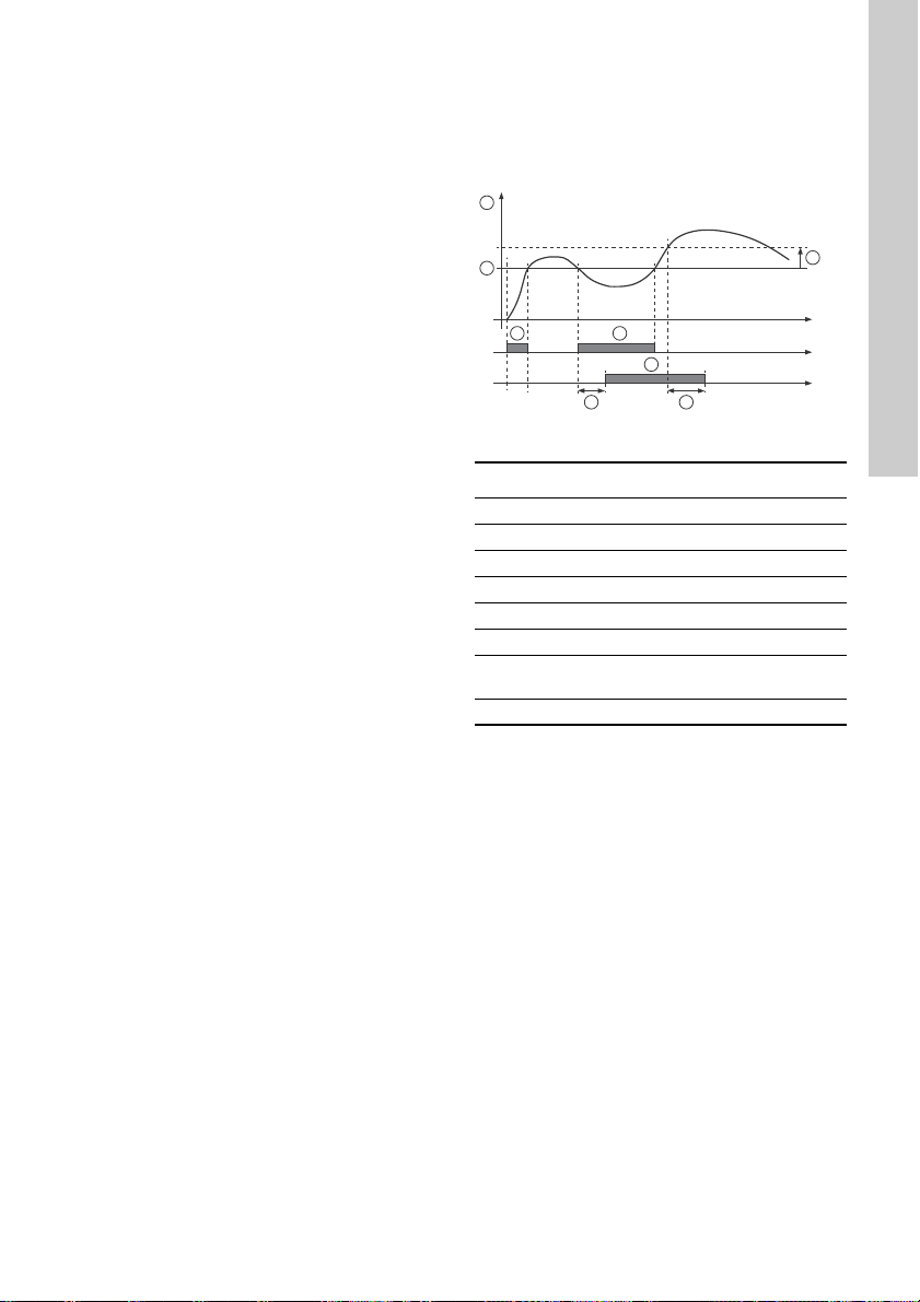
10.15 ""Limit-exceeded function""
1
2
4 4
5 6
3
A
Time [s]
This function can monitor a measured parameter or
one of the internal values such as speed, motor load
or motor current. If a set limit is reached, a selected
action can take place. You can set two
limit-exceeded functions meaning that you can
monitor two parameters or two limits of the same
parameter simultaneously.
Example
The function is to monitor the outlet pressure from a
CRE pump. If the pressure is below 5 bar for more
than 5 seconds, a warning must be given. If the
outlet pressure is above 7 bar for more than 8
seconds, reset the limit exceeded warning.
English (GB)
The function requires setting of the following:
"Measured"
Here you set the measured parameter which is to be
monitored.
"Limit"
Here you set the limit which activates the function.
"Hysteresis band"
Here you set the hysteresis band.
"Limit exceeded when"
Here you can set if you want the function to be
activated when the selected parameter exceeds or
drops below the set limit.
• ""Above limit""
The function is activated if the measured
parameter exceeds the set limit.
• ""Below limit""
The function is activated if the measured
parameter drops below the set limit.
"Action"
If the value exceeds a limit, you can set an action.
You can select the following actions:
• ""No action""
The pump remains in its current state. Use this
setting if you only want to have a relay output
when the limit is reached. See section
10.9 "Signal relay" (""Relay outputs"").
• ""Warning/alarm""
A warning is given.
• ""Stop""
The pump stops.
•""Min.""
The pump reduces speed to minimum.
•""Max.""
The pump increases speed to maximum.
Fig. 44 Limit exceeded (example)
Pos. Setting parameter Setting
1 "Measured" Outlet pressure
2 "Limit" 5 bar
3 "Hysteresis band" 2 bar
4 "Limit exceeded when" Below limit
5 "Detection delay" 5 seconds
6 "Resetting delay" 8 seconds
"Limit exceeded function
A
active"
-
- "Action" Warning
TM06 4603 2515
Detection delay
You can set a detection delay which ensures that the
monitored parameter stays above or below a set limit
in a set time before the function is activated.
Resetting delay
The resetting delay is the time from which the
measured parameter differs from the set limit
including the set hysteresis band and until the
function is reset.
41
Page 42

10.16 "Ramps"
User-set ramp-up User-set ramp-down
Spee d
Time
User-set
minimum
Fixed initial ramp Fixed final
ramp
User-set
maximum
Fixed
maximum
0
English (GB)
The ramps determine how quickly the motor can
accelerate and decelerate during start/stop or
setpoint changes.
You can set the following:
• acceleration time, 0.1 to 300 s
• deceleration time, 0.1 to 300 s.
The times apply to the acceleration from 0 rpm to
maximum (fixed) speed and the deceleration from
maximum (fixed) speed to 0 rpm, respectively.
At short deceleration times, the deceleration of the
motor may depend on load and inertia as there is no
possibility of actively braking the motor.
If the power supply is switched off, the deceleration
of the motor only depends on load and inertia.
Fig. 45 Ramp-up and ramp-down
10.17 "Direction of rotation"
Select the desired direction of rotation of the motor
when seen from the drive end:
• clockwise
• counter-clockwise.
The displayed direction of rotation applies when the
digital inputs for reversing the rotation are not active.
See sections 10.7 "Digital inputs" and 10.8 ""Digital
inputs/outputs"".
10.18 "Skip band"
Select a skip band within the range from user-set
minimum speed to user-set maximum speed if
continuous operation is not required. The upper and
lower speeds are stated in % of rated speed.
The purpose of the skip band is to avoid certain
speeds which may cause noise or vibrations. If no
skip band is required, select "-".
10.19 ""Standstill heating""
You can use the function to avoid condensation in
humid environments. When you set the function to
""Active"" and the motor is in operating mode
""Stop"", a low AC voltage is applied to the motor
windings. The voltage is not high enough to make
the motor rotate but ensures that sufficient heat is
generated to avoid condensation in the motor
including the electronic parts in the drive.
Remember to remove the drain plugs and
fit a cover over the motor.
10.20 ""Motor bearing monitoring""
You can set the "motor bearing monitoring" function
to these values:
•""Active""
• ""Not active"".
When the function is set to ""Active"", a counter in
the controller starts counting the mileage of the
bearings.
The counter continues counting even if
you change the function to ""Not active"",
but a warning will not be given when it is
time for replacement.
When you change the function to ""Active""
TM03 9439 0908
again, the accumulated mileage is again
used to calculate the replacement time.
42
Page 43

10.21 "Service"
"Time to next service" (""Motor bearing
service"")
This display shows when to replace the motor
bearings. The controller monitors the operating
pattern of the motor and calculates the period
between bearing replacements.
Displayable values:
• "in 2 years"
• "in 1 year"
• "in 6 months"
• "in 3 months"
• "in 1 month"
• "in 1 week"
•"Now"
"Bearing replacements"
Indicates the number of bearing replacements that
have been done during the lifetime of the motor.
"Bearings replaced" (""Motor bearing
maintenance"")
When the bearing monitoring function is active, the
controller gives a warning when the motor bearings
are due to be replaced.
When you have replaced the motor bearings, press
[Bearings replaced].
10.22 "Number" (""Pump number"")
You can allocate a unique number to the motor. This
makes it possible to distinguish between motors in
connection with GENIbus communication.
10.23 "Radio communication"
(""Enable/disable radio comm."")
You can set the radio communication to "enabled" or
"disabled". Use this function in areas where radio
communication is not allowed.
IR communication remains active.
10.24 ""Language""
This menu is only available in the advanced control
panel.
In this menu, you select the desired language. A
number of languages is available.
10.25 "Date and time" (""Set date and time"")
The availability of this menu depends on the
functional module fitted in the motor.
Function (terminal)
"Date and time" - ●
* See section 15. Identification of functional
module.
You can set date and time as well as how you want
them to be viewed in the display:
• ""Select date format":"
""YYYY-MM-DD""
""DD-MM-YYYY""
""MM-DD-YYYY"".
• ""Select time format"":
""HH:MM 24-hour clock""
""HH:MM am/pm 12-hour clock"".
• ""Set date""
• ""Set time"".
FM 200*
(standard)
FM 300*
(advanced)
10.26 "Unit configuration" (""Units"")
In this menu, you can select between SI and US
units. The setting can be made generally for all
parameters or you can customise for each individual
parameter.
10.27 "Buttons on product" (""Enable/disable settings"")
In this display, you can disable the possibility of
making settings for protective reasons.
Grundfos GO
If you set the buttons to "Not active" the buttons on
the standard control panel are disabled. If you set
the buttons to "Not active" on pumps fitted with an
advanced control panel, see below.
Advanced control panel
If you have disabled the settings, you can still use
the buttons to navigate through the menus but you
cannot make changes in the ""Settings"" menu.
When you have disabled the possibility to make
settings, the symbol appears in the display.
Advanced control panel:
To unlock the motor and allow settings,
press and simultaneously for at least
5 seconds.
Standard control panel:
The button always remains active but
you can only unlock all other buttons on
the motor with Grundfos GO.
English (GB)
43
Page 44

10.28 ""Delete history""
English (GB)
This menu is only available in the advanced control
panel.
In this menu, you can delete the following historic
data:
• ""Delete operating log"".
• ""Delete energy consumption"".
10.29 ""Define Home display""
This menu is only available in the advanced control
panel.
In this menu, you can set the ""Home"" display to
show up to four user-defined parameters.
10.30 ""Display settings""
This menu is only available in the advanced control
panel.
In this menu, you can adjust the display brightness
and set whether or not the display is to turn off if no
buttons have been activated for a period of time.
10.31 "Store settings" (""Store actual settings"")
Grundfos GO
In this menu, you can store the actual settings for
later use in the same motor or in other motors of the
same type.
Advanced control panel
In this menu, you can store the actual settings for
later use in the same motor.
10.32 "Recall settings" (""Recall stored settings"")
Grundfos GO
In this menu, you can recall stored settings from a
number of previously stored settings that the motor
then uses.
Advanced control panel
In this menu, you can recall the last stored settings
that the motor then uses.
10.32.1 "Undo"
This menu is only available in Grundfos GO.
In this display, you can undo all settings that have
been made with Grundfos GO in the current
communication session. Once you have recalled
settings, you cannot undo.
10.33 "Pump name" (motor name)
This menu is only available in Grundfos GO.
In this display, you can give the motor a name. In this
way, you can easily identify the motor when
connecting with Grundfos GO.
10.34 "Connection code"
This menu is only available in Grundfos GO.
You can set a connection code to avoid having to
press the connection button each time and to restrict
remote access to the product.
Setting the code in the product using Grundfos
GO
1. Connect Grundfos GO to the product.
2. In the product dashboard, select "Settings".
3. Select "Connection code".
4. Enter the wanted code and press [OK].
The code must be a character string (ASCII). You
can always change the code. The old code is not
needed.
Setting the code in Grundfos GO
You can set a default connection code in Grundfos
GO so that it automatically attempts to connect to the
selected product via this code.
When you select a product with the same connection
code in Grundfos GO, Grundfos GO automatically
connects to the product and you do not have to press
the connection button on the module.
Set the default code in Grundfos GO in this way:
1. In the main menu, under "General", select
"Settings".
2. Select "Remote".
3. Enter the connection code in the field "Preset
connection code". The field now says
"Connection code set".
You can always change the default connection code
by pressing [Delete] and entering a new one.
If Grundfos GO fails to connect and ask you to press
the connection button on the product, it means that
the product has no connection code or has a
different connection code. In this case, you can only
establish connection via the connection button.
After setting a connection code, switch off
the product until the light in Grundfos Eye
turns off before you can use the new
connection code.
44
Page 45

10.35 ""Run start-up guide""
This menu is only available in the advanced control
panel.
The startup guide automatically starts when you start
the motor for the first time.
You can always run the startup guide later via this
menu.
The startup guide guides you through the general
settings of the motor.
• ""Language"". See section 10.24 ""Language"".
• ""Select date format"".*
See section 10.25 "Date and time" (""Set date
and time"").
• ""Set date"".*
See section 10.25 "Date and time" (""Set date
and time"").
• ""Select time format"".*
See section 10.25 "Date and time" (""Set date
and time"").
• ""Set time"".*
See section 10.25 "Date and time" (""Set date
and time"").
• Setting the motor
– ""Go to Home""
– ""Run with Constant curve""/""Run with
Constant pressure"".
See section 10.4 "Control mode".
– ""Go to "Assisted pump setup""".
See section 10.39 ""Assisted pump setup""
(Assisted motor setup).
– ""Return to factory settings"".
* Applies only for motors fitted with an advanced
functional module, type FM 300. See section
15. Identification of functional module.
10.36 ""Alarm log""
This menu contains a list of logged alarms from the
product. The log shows the name of the alarm, when
the alarm occurred and when it was reset.
10.37 ""Warning log""
This menu contains a list of logged warnings from
the product. The log shows the name of the warning,
when the warning occurred and when it was reset.
10.38 ""Assist""
This menu consist of a number of different assist
functions which are small guides that take you
through the steps needed to set the motor.
10.39 ""Assisted pump setup"" (Assisted motor setup)
This menu guides you through the following:
Setting the motor
• Selection of control mode. See page 32.
• Configuration of feedback sensors.
• Adjusting the setpoint. See page 32.
• "Controller settings". See page 37.
• Summary of settings.
Example of how to use the ""Assisted pump
setup"" for setting the motor to "Constant other
value"
Grundfos GO
1. Open the ""Assist"" menu.
2. Select ""Assisted pump setup"".
3. Select control mode "Constant other value"
(""Const. other val."").
4. Read the description for this control mode.
5. Select which analog input to use as sensor input.
6. Select sensor function "Other parameter".
7. Select electrical input signal according to the
sensor specifications.
8. Select measuring unit according to the sensor
specifications.
9. Set the minimum and maximum sensor range
values according to the sensor specifications.
10. Set the desired setpoint.
11. Set the gain and integral time of the controller.
See section 10.11 "Controller" (""Controller
settings"").
12. Type the desired motor name.
13. Check the summary of settings and confirm
them.
English (GB)
45
Page 46

Advanced control panel
English (GB)
1. Open the ""Assist"" menu.
2. Select ""Assisted pump setup"".
3. Select control mode ""Const. other val."".
4. Select which analog input to be used as sensor
input.
5. Select the measured parameter which is to be
controlled. See fig. 28.
6. Select measuring unit according to the sensor
specifications.
7. Set the minimum and maximum sensor range
values according to the sensor specifications.
8. Select electrical input signal according to the
sensor specifications.
9. Set the desired setpoint.
10. Set the gain and integral time of the controller.
See section 10.11 "Controller" (""Controller
settings"").
11. Check the summary of settings and confirm them
by pressing [OK].
10.40 ""Setup, analog input""
This menu is only available in the advanced control
panel.
This menu guides you through the following:
""Setup, analog input""
• "Analog inputs" 1 to 3. See page 32.
• "Pt100/1000 input" 1 and 2. See page 33.
• "Adjusting the setpoint". See page 32.
•"Summary".
10.41 ""Setting of date and time""
This menu is only available in the advanced control
panel.
Whether this menu is available or not, depends on
the functional module fitted in the pump:
Function (terminal)
"Setting of date and
time"
* See section 15. Identification of functional
module.
This menu guides you through the following:
• ""Select date format"". See section 10.25 "Date
and time" (""Set date and time"").
• ""Set date"". See section 10.25 "Date and time"
(""Set date and time"").
• ""Select time format"". See section 10.25 "Date
and time" (""Set date and time"").
• ""Set time"". See section 10.25 "Date and time"
(""Set date and time"").
FM 200*
(standard)
- ●
FM 300*
(advanced)
10.42 ""Setup of multi-pump system"" (Multimotor)
The multimotor function enables the control of two
motors connected in parallel without the use of
external controllers. The motors in a multimotor
system communicate with each other via the
wireless GENIair connection or the wired GENI
connection.
You can set a multimotor system via the master
motor, i.e. the first selected motor.
If two motors in the system are configured with an
outlet-pressure sensor, they can all function as
master motors and take over the master motor
function if the other fails. This provides additional
redundancy in the multimotor system.
The multimotor functions are described in the
following sections.
46
Page 47

10.42.1 "Alternating operation"
Alternating operation functions as a duty/standby
operating mode and is possible with two motors of
same size and type connected in parallel. The main
purpose of the function is to ensure an even amount
of running hours and to ensure that the other motor
starts if the duty motor stops due to an alarm.
You can choose between two alternating operation
modes:
• "Alternating operation, time"
Change from one motor to the other is based on
time.
• "Alternating operation, energy"
Change from one motor to the other is based on
energy consumption.
If the duty motor fails, the other motor starts.
10.42.2 "Backup operation"
"Backup operation" is possible with two motors of
same size and type connected in parallel.
One motor is operating continuously. The backup
motor is operated for a short time each day to
prevent seizing up. If the duty motor stops due to a
fault, the backup motor starts.
10.42.3 Setting a multimotor system
You can set a multimotor system in the following
ways:
• Grundfos GO and wireless motor connection
• Grundfos GO and wired motor connection
• Advanced control panel and wireless motor
connection
• Advanced control panel and wired motor
connection.
See step-by-step descriptions below.
Grundfos GO and wireless motor connection
1. Power on both motors.
2. Establish contact to one of the motors with
Grundfos GO.
3. Set the needed analog and digital inputs via
Grundfos GO according to the connected
equipment and the required functionality. See
section 10.39 ""Assisted pump setup"" (Assisted
motor setup).
4. Assign a name to the motor using Grundfos GO.
See section 10.33 "Pump name" (motor name).
5. Disconnect Grundfos GO from the motor.
6. Establish contact to the other motor.
7. Set the needed analog and digital inputs via
Grundfos GO according to the connected
equipment and the required functionality. See
section 10.39 ""Assisted pump setup"" (Assisted
motor setup).
8. Assign a name to the motor using Grundfos GO.
See section 10.33 "Pump name" (motor name).
9. Select the "Assist" menu and ""Setup of
multi-pump system"".
10. Select the desired multimotor function. See
sections 10.42.1 "Alternating operation" and
10.42.2 "Backup operation".
11. Press [>] to continue.
12. Set the time for motor changeover, i.e. the time at
which the alternation between the two motors is
to take place.
This step applies only if you have selected
"Alternating operation, time" and if the
motors are fitted with FM 300.
13. Press [>] to continue.
14. Select "Radio" as the communication method to
be used between the two motors.
15. Press [>] to continue.
16. Press "Select pump 2" (motor 2).
17. Select the pump from the list.
Use the [OK] or button to identify the
pump.
18. Press [>] to continue.
19. Confirm the setting by pressing [Send].
20. Press [Finish] in the "Setup complete" dialog box.
21. Wait for the green indicator light in the middle of
Grundfos Eye to light up.
English (GB)
47
Page 48

Grundfos GO and wired motor connection
English (GB)
1. Connect the two motors with each other with a
3-core screened cable between the GENIbus
terminals A, Y, B.
2. Power on both motors.
3. Establish contact to one of the motors with
Grundfos GO.
4. Set the needed analog and digital inputs via
Grundfos GO according to the connected
equipment and the required functionality. See
section 10.39 ""Assisted pump setup"" (Assisted
motor setup).
5. Assign a name to the motor using Grundfos GO.
See section 10.33 "Pump name" (motor name).
6. Assign motor number 1 to the motor. See section
10.22 "Number" (""Pump number"").
7. Disconnect Grundfos GO from the motor.
8. Establish contact to the other motor.
9. Set the analog and digital inputs according to the
connected equipment and the required
functionality by means of Grundfos GO. See
section 10.39 ""Assisted pump setup"" (Assisted
motor setup).
10. Assign a name to the motor using Grundfos GO.
See section 10.33 "Pump name" (motor name).
11. Assign motor number 2 to the motor. See section
10.22 "Number" (""Pump number"").
12. Select the "Assist" menu and ""Setup of
multi-pump system"" (multimotor setup).
13. Select the desired multimotor function. See
sections 10.42.1 "Alternating operation" and
10.42.2 "Backup operation".
14. Press [>] to continue.
15. Set the time for motor changeover, i.e. the time at
which the alternation between the two motors is
to take place.
This step applies only if you have selected
"Alternating operation, time" and if the
motors are fitted with FM 300.
16. Press [>] to continue.
17. Select "BUS cable" as the communication
method to be used between the two motors.
18. Press [>] to continue.
19. Press "Select pump 2" (motor 2).
20. Select the additional motor from the list.
Advanced control panel and wireless motor
connection
1. Power on both motors.
2. On both motors, set the analog and digital inputs
according to the connected equipment and the
required functionality. See section
10.39 ""Assisted pump setup"" (Assisted motor
setup).
3. Select the ""Assist"" menu on one of the motors
and ""Setup of multi-pump system"" (setup of
multimotor system).
4. Press [>] to continue.
5. Select ""Wireless"" as the communication
method to be used between the two motors.
6. Press [>] to continue.
7. Select the desired multimotor function. See
sections 10.42.1 "Alternating operation" and
10.42.2 "Backup operation".
8. Press [>] three times to continue.
9. Press [OK] to search for other motors.
The green indicator light in the middle of
Grundfos Eye flashes on the other motors.
10. Press the connect button on the motor which is to
be added to the multimotor system.
11. Press [>] to continue.
12. Set the time for motor changeover, i.e. the time at
which the alternation between the two motors is
to take place.
This step applies only if you have selected
"Alternating operation, time" and if the
motors are fitted with FM 300.
13. Press [>] to continue.
14. Press [OK] to confirm the setting.
The multimotor function icons appear in the
bottom of the control panels.
Use the [OK] or button to identify the
pump.
21. Press [>] to continue.
22. Confirm the setting by pressing [Send].
23. Press [Finish] in the "Setup complete" dialog box.
24. Wait for the green indicator light in the middle of
Grundfos Eye to light up.
48
Page 49

Advanced control panel and wired motor
connection
1. Connect the two motors with each other with a
3-core screened cable between the GENIbus
terminals A, Y, B.
2. Set the needed analog and digital inputs
according to the connected equipment and the
required functionality. See section
10.39 ""Assisted pump setup"" (Assisted motor
setup).
3. Assign motor number 1 to the first motor. See
section 10.22 "Number" (""Pump number"").
4. Assign motor number 2 to the other motor. See
section 10.22 "Number" (""Pump number"").
5. Select the ""Assist"" menu on one of the motors
and ""Setup of multi-pump system"".
6. Press [>] to continue.
7. Select ""Wired GENIbus"" as the communication
method to be used between the two motors.
8. Press [>] twice to continue.
9. Select the desired multimotor function. See
sections 10.42.1 "Alternating operation" and
10.42.2 "Backup operation".
10. Press [>] to continue.
11. Press [OK] to search for other motors.
12. Select the additional motor from the list.
13. Press [>] to continue.
14. Set the time for motor changeover, i.e. the time at
which the alternation between the two motors is
to take place.
This step applies only if you have selected
"Alternating operation, time" and if the
motors are fitted with FM 300.
15. Press [>] to continue.
16. Press [OK] to confirm the setting. The multimotor
function icons appear in the bottom of the control
panels.
Disabling a multimotor system via Grundfos GO
1. Select the "Assist" menu.
2. Select ""Setup of multi-pump system""
(multimotor setup).
3. Select "Disable".
4. Press [>] to continue.
5. Confirm the setting by pressing [Send].
6. Press [Finish].
Disabling a multimotor system via advanced
control panel
1. Select the ""Assist"" menu.
2. Select ""Setup of multi-pump system"".
3. Press [>] to continue.
4. Press [OK] to confirm ""No multi-pump function"".
5. Press [>] to continue.
6. Press [OK] to confirm.
10.43 ""Description of control mode""
This menu is only available in the advanced control
panel.
This menu describes each of the possible control
modes. See also section 10.4 "Control mode".
10.44 ""Assisted fault advice""
This menu gives guidance and corrective actions in
case of motor failures.
11. Bus signal
The motor enables serial communication via an
RS-485 input. The communication is carried out
according to the Grundfos GENIbus protocol and
enables connection to a building management
system or another external control system.
Via a bus signal, you can remote-set operating
parameters, such as setpoint and operating mode. At
the same time, the motor can, via the bus, provide
status information about important parameters, such
as actual value of the control parameter, input power
and fault indications.
Contact Grundfos for further information.
If you use a bus signal, the number of
settings available via R100 or Grundfos
GO are reduced.
English (GB)
49
Page 50

12. Priority of settings
English (GB)
You can always set the motor to operation at
maximum speed or to stop with R100 or Grundfos
GO.
If two or more functions are enabled at the same
time, the motor operates according to the function
with the highest priority.
Example
If you have set the motor to maximum speed via the
digital input, the motor control panel, R100 or
Grundfos GO can only set the motor to "Manual" or
"Stop".
The priority of the settings appears from the table
below:
Priority
1 Stop
2 Stop*
3 Manual
4 Maximum speed*
5 Stop
6 Stop
7 Maximum speed
8 Minimum speed
9 Start
10 Maximum speed
11 Minimum speed
12 Minimum speed
13 Start
14 Start
* "Stop" and "Max. speed" settings made with
R100, Grundfos GO or on the motor control panel
can be overruled by another operating-mode
command sent from a bus, for example "Start". If
the bus communication is interrupted, the motor
resumes its previous operating mode, for
example "Stop", selected with R100, Grundfos
GO or on the motor control panel.
Start/stop
button
R100, Grundfos GO or
control panel on motor
Digital input Bus communication
50
Page 51

13. Grundfos Eye
A
The operating condition of the motor is indicated by
Grundfos Eye on the motor control panel. See fig.
46, pos. A.
TM05 4846 2712
Fig. 46 Grundfos Eye
Grundfos Eye Indication Description
No lights are on.
The two opposite green indicator
lights are rotating in the direction
of rotation of the motor when
seen from the non-drive end.
The two opposite green indicator
lights are permanently on.
One yellow indicator light is
rotating in the direction of rotation
of the motor when seen from the
non-drive end.
One yellow indicator light is
permanently on.
Two opposite red indicator lights
flash simultaneously.
The green indicator light in the
middle flashes quickly four times.
The green indicator light in the
middle flashes continuously.
The green indicator light in the
middle is permanently on.
The green indicator light in the
middle flashes quickly while
R100 or Grundfos GO is
exchanging data with the motor.
It takes a few seconds.
The power is off.
The motor is not running.
The power is on.
The motor is running.
The power is on.
The motor is not running.
Warning.
The motor is running.
Warning.
The motor has stopped.
Alarm.
The motor has stopped.
Remote control with Grundfos GO via
radio.
The motor is trying to communicate with
Grundfos GO. The motor is highlighted in
the Grundfos GO display to inform the user
of the location of the motor.
When you have selected the motor in the
Grundfos GO menu, the green indicator
light in the middle flashes continuously.
Press on the motor control panel to
allow remote control and data exchange via
Grundfos GO.
Remote control with Grundfos GO via
radio.
The motor is communicating with Grundfos
GO via radio connection.
Remote control with R100 or Grundfos GO
via infrared light.
The motor is receiving data from R100 or
Grundfos GO via infrared communication.
English (GB)
51
Page 52
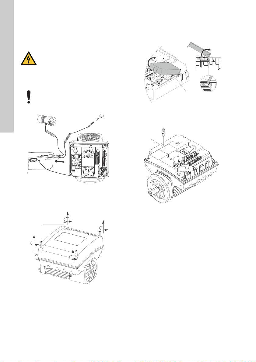
14. Installing a communication
A
B
B
C
D
A
A
English (GB)
interface module
DANGER
Electric shock
- Death or serious personal injury
- Switch off the power supply to the motor
and to the signal relays. Wait at least 5
minutes before you make any
connections in the terminal box. Make
sure that the power supply cannot be
accidentally switched on.
Always use an antistatic service kit when
handling electronic components. This
prevents static electricity from damaging
the components.
Fig. 47 Antistatic service kit
1. Loosen the four screws (fig. 48, A) and remove
the terminal box cover (fig. 48, B).
2. Remove the CIM cover (fig. 49, A) by pressing
the locking tab (fig. 49, B) and lifting the end of
the cover (fig. 49, C). Then lift the cover off the
hooks (fig. 49, D).
Fig. 49 Removing the CIM cover
3. Remove the securing screw (fig. 50, A).
TM06 4462 2315TM06 4081 1515
Fig. 50 Removing the securing screw
TM06 4084 1515TM06 4082 1515
Fig. 48 Removing the terminal box cover
52
Page 53

4. Fit the CIM module by aligning it with the three
A
B
A
FCC
plastic holders (fig. 51, A) and the connecting
plug (fig. 51, B). Press home the module using
your fingers.
8. Route the wires for the CIM module. See the
example in fig. 53.
English (GB)
Fig. 51 Fitting the CIM module
5. Fit and tighten the securing screw (fig. 50, A) to
1.3 Nm.
6. Make the electrical connections to the CIM
module as described in the instructions delivered
with the module.
7. Connect the cable screens of the bus cables to
earth via one of the earth clamps (fig. 52, A).
Fig. 52 Connecting the cable screens to earth
TM06 4083 1515TM06 4195 1615
Fig. 53 Example of wire routing
9. Fit the CIM cover.
10. If the CIM module is supplied with an FCC label,
place the label on the terminal box. See fig. 54.
Fig. 54 FCC label
11. Fit the terminal box cover (fig. 48, B) and
cross-tighten the four mounting screws (fig. 48,
A) to 6 Nm.
Make sure that the terminal box cover is
aligned with the control panel. See section
17. Changing the position of the control
panel.
TM06 4085 1515TM05 7028 0413
53
Page 54

15. Identification of functional module
Env.Type :
Serial no :
SF CL:
PF:
PB
FM
HMIEff
n max:
CIMWgt
:
DE
:
kg
NDE
:
T
amb
:
:
FAA
V
~
P.C.
:
Made in Hungary
OUTPUT
VARIANT
INPUT
TEFC
Type
:
P.N.
:
U
in
:
I
1/1
:
f
in
HpHzP2
I
SF Amp:
rpm
:::
:
:
:
:
Xxxxxxxxxxx
E.P. Motor
DK - 8850 Bjerringbro, Denmark
.
yyp
p
:
S
a
o
:
SF
C
:
:
Eff
n
g
g
t
:
DE
:
g
g
NDE
:
T
a
b
:
:
FAA
.C.
:
PU
T
E
C
yp
yp
e
:
P.N.
:
U
n
:
I
1/1
:
n
I
S
p
p
:
:
PB
FM
HMI
CIM
VARIANT
Hp
rpm
:
:
:
:
PB
:
HMI
:
C
:
H
p
pm
Env.Type :
Serial no :
SF CL:
PF:
PB
FM
HMIEff
n max:
CIMWgt
:
DE
:
kg
NDE
:
T
amb
:
:
FAA
V
~
P.C.
:
Made in Hungary
OUTPUT
VARIANT
INPUT
TEFC
Type
:
P.N.
:
U
in
:
I
1/1
:
f
in
HpHzP2
I
SF Amp:
rpm
:::
:
:
:
:
Xxxxxxxxxxx
E.P. Motor
DK - 8850 Bjerringbro, Denmark
.
yyp
p
:
S
a
o
:
SF
C
:
:
Eff
n
g
g
t
:
DE
:
g
g
NDE
:
T
a
b
:
:
FAA
.C.
:
PU
T
E
C
yp
yp
e
:
P.N.
:
U
n
:
I
1/1
:
n
I
S
p
p
:
:
PB
FM
HMI
CIM
VARIANT
Hp
rpm
:
:
:
:
PB
:
C
:
H
p
pm
FM
:
English (GB)
You can identify the fitted module in one of the
following ways:
Grundfos GO
You can identify the functional module in the "Fitted
modules" menu under "Status".
Motor display
For motors fitted with the advanced control panel,
you can identify the functional module in the ""Fitted
modules"" menu under ""Status"".
Motor nameplate
You can identify the fitted module on the motor
nameplate. See fig. 55.
16. Identification of control panel
You can identify the fitted module in one of the
following ways:
Grundfos GO
You can identify the control panel in the "Fitted
modules" menu under "Status".
Motor display
For motors fitted with the advanced control panel,
you can identify the control panel in the ""Fitted
modules"" menu under ""Status"".
Motor nameplate
You can identify the fitted control panel on the motor
nameplate. See fig. 56.
IN
i
eri
e
F
i
L
F Am
r
IM
eri
n
TM06 1889 3314
Fig. 55 Identification of functional module
Variant Designation
FM 100 Basic functional module
FM 200 Standard functional module
FM 300 Advanced functional module
Fig. 56 Identification of control panel
Variant Designation
HMI 100 Basic control panel
HMI 200 Standard control panel
HMI 300 Advanced control panel
IN
i
e
F
i
L
F Am
r
IM
TM06 4013 1415
54
Page 55
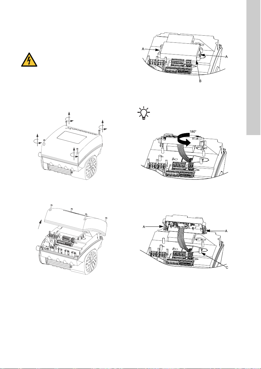
17. Changing the position of the control panel
DANGER
Electric shock
- Death or serious personal injury
- Switch off the power supply to the motor
and to the signal relays. Wait at least 5
minutes before you start any work on
the motor. Make sure that the power
supply cannot be accidentally switched
on.
You can turn the control panel 180 °. Follow the
instructions below.
1. Loosen the four screws (TX25) of the terminal
box cover.
3. Press and hold in the two locking tabs (A) while
gently lifting the plastic cover (B).
Fig. 59 Lifting the plastic cover
4. Turn the plastic cover 180 °.
Do not twist the cable more than 90 °.
English (GB)
TM05 5353 3612
Fig. 57 Loosening the screws
2. Remove the terminal box cover.
Fig. 58 Removing the terminal box cover
TM064915 3115TM064926 3115
Fig. 60 Turning the plastic cover
5. Position the plastic cover correctly on the four
rubber pins (C). Make sure that the locking tabs
(A) are placed correctly.
Fig. 61 Positioning the plastic cover
TM05 5354 3612TM05 5355 3612
55
Page 56

6. Fit the terminal box cover, and make sure that it
English (GB)
is also turned 180 ° so that the buttons on the
control panel are aligned with the buttons on the
plastic cover.
7. Tighten the four screws (TX25) with 5 Nm.
Fig. 62 Fitting the terminal box cover
18. Servicing the product
DANGER
Electric shock
- Death or serious personal injury
- Switch off the power supply to the motor
and to the signal relays. Wait at least 5
minutes before starting any work on the
motor. Make sure that the power supply
cannot be accidentally switched on.
DANGER
Magnetic field
Death or serious personal injury
- Do not handle the motor or rotor if you
have a pacemaker.
For servicing the product, download the service
instructions for the motor by using the following link
or QR code.
19. Cleaning the product
WARNING
Electric shock
- Death or serious personal injury
- Switch off the power supply to the motor
and to the signal relays. Check that the
terminal box cover is intact before
spraying water on the product.
In order to avoid condensation in the motor, let the
motor cool down before spraying it with cold water.
TM064929 3115
http://net.grundfos.com/qr/i/98413121
56
QR98413121
Page 57

20. Signal relays
NCNO
C
NCNO
C
NCNO
C
NCNO
C
NCNO
C
C
NO NC
C
NO NC
C
NO NC
NCNO
C
NCNO
C
C
NO NC
C
NO NC
NCNO
C
NCNO
C
NCNO
C
NCNOCNCNO
C
C
NO NC
NCNO
C
NCNO
C
C
NO NC
C
NO NC
C
NO NC
NCNO
C
C
NO NC
C
NO NC
C
NO NC
NCNO
C
NCNO
C
C
NO NC
NCNO
C
NCNO
C
C
NO NC
NCNO
C
C
NO NC
C
NO NC
C
NO NC
NCNO
C
C
NO NC
NCNO
C
C
NO NC
C
NO NC
NCNO
C
C
NO NC
NCNO
C
NCNO
C
NCNO
C
NCNO
C
C
NO NC
NCNO
C
The motor has two outputs for potential-free signals
via two internal relays.
You can set the signal outputs to "Operation",
"Running", "Ready", "Alarm" and "Warning".
The functions of the two signal relays appear from
the table below:
Description Grundfos Eye
Contact position of signal relays when activated
Operation Running Ready Alarm Warning
Operating
mode
English (GB)
The power is
off.
The motor runs
in "Normal"
mode in open
or closed loop.
The motor runs
in "Manual"
mode.
The motor is in
operating mode
"Stop".
Warning, but
the motor is
running.
Warning, but
the motor runs
in "Manual"
mode.
Warning, but
the motor was
stopped via a
"Stop"
command.
Alarm, but the
motor is
running.
Off
Green, rotating
Green, rotating
Green, steady
Yellow, rotating
Yellow, rotating
Yellow, steady
Red, rotating
-
"Normal",
"Min." or
"Max."
"Manual"
"Stop"
"Normal",
"Min." or
"Max."
"Manual"
"Stop"
"Normal",
"Min." or
"Max."
Alarm, but the
motor runs in
"Manual" mode.
The motor has
been stopped
due to an
alarm.
Red, rotating
Red, flashing
"Manual"
"Stop"
57
Page 58

21. Megging
English (GB)
Do not meg an installation incorporating MGE
motors, as the built-in electronics may be damaged.
22. Technical data, single-phase motors
22.1 Supply voltage
Single-phase motors are available for the voltages
below:
• 1 x 200-240 V - 10 %/+ 10 %, 50/60 Hz, PE
• 1 x 90-240 V - 10 %/+ 10 %, 50/60 Hz, PE or
30-300 VDC (power supply from a
renewable-energy source).
Check that the supply voltage and frequency
correspond to the values stated on the nameplate.
Recommended fuse size
Motor size
[kW]
0.25 - 0.75 6 10
1.1 - 1.5 10 16
You can use standard as well as quick-blow or
slow-blow fuses.
22.2 Leakage current
Earth leakage current less than 3.5 mA (AC).
Earth leakage current less than 10 mA (DC).
The leakage currents are measured in accordance
with EN 61800-5-1:2007.
Minimum
[A]
Maximum
[A]
23. Technical data, three-phase motors
23.1 Supply voltage
• 3 x 380-500 V - 10 %/+ 10 %, 50/60 Hz, PE.
Check that the supply voltage and frequency
correspond to the values stated on the nameplate.
Recommended fuse size
Motor size
[kW]
0.25 - 1.1 6 6
1.5 6 10
2.2 6 16
31016
41316
5.5 16 32
7.5 20 32
11 32 32
You can use standard as well as quick-blow or
slow-blow fuses.
23.2 Leakage current (AC)
Speed
-1
[min
]
0.25 - 1.5
1400-2000
1450-2200
5.5 - 7.5
0.25 - 2.2
2900-4000
0.25 - 2.2
4000-5900
The leakage currents are measured without any load
on the shaft and in accordance with EN
61800-5-1:2007.
Power
[kW]
2.2 - 4
3 - 5.5
7.5 - 11
3 - 5.5
7.5 - 11
Minimum
[A]
Mains
voltage
[V]
≤ 400 < 3.5
> 400 < 5
≤ 400 < 3.5
> 400 < 3.5
≤ 400 < 3.5
> 400 < 5
≤ 400 < 3.5
> 400 < 5
≤ 400 < 3.5
> 400 < 3.5
≤ 400 < 3.5
> 400 < 5
≤ 400 < 3.5
> 400 < 5
≤ 400 < 3.5
> 400 < 3.5
≤ 400 < 3.5
> 400 < 5
Maximum
[A]
Leakage
current
[mA]
58
Page 59

24. Inputs and outputs
Earth reference
All voltages refer to earth. All currents return to
earth.
Absolute maximum voltage and current limits
Exceeding the following electrical limits may result in
severely reduced operating reliability and motor life:
Relay 1:
Maximum contact load: 250 VAC, 2 A or 30 VDC, 2
A.
Relay 2:
Maximum contact load: 30 VDC, 2 A.
GENI terminals: -5.5 - 9.0 VDC or less than 25
mADC.
Other input/output terminals: -0.5 - 26 VDC or less
than 15 mADC.
Digital inputs
Internal pull-up current > 10 mA at V
Internal pull-up to 5 VDC (currentless for V
VDC).
Certain low logic level: V
Certain high logic level: V
less than 1.5 VDC.
i
greater than 3.0 VDC.
i
Hysteresis: No.
Screened cable: 0.5 - 1.5 mm
Maximum cable length: 500 m.
Open-collector digital outputs (OC)
Current sinking capability: 75 mADC, no current
sourcing.
Load types: Resistive or/and inductive.
Low-state output voltage at 75 mADC: Maximum 1.2
VDC.
Low-state output voltage at 10 mADC: Maximum 0.6
VDC.
Overcurrent protection: Yes.
Screened cable: 0.5 - 1.5 mm
Maximum cable length: 500 m.
= 0 VDC.
i
2
/ 28-16 AWG.
2
/ 28-16 AWG.
> 5
i
Analog inputs (AI)
Voltage signal ranges:
• 0.5 - 3.5 VDC, AL AU.
• 0-5 VDC, AU.
• 0-10 VDC, AU.
Voltage signal: R
Leak currents may occur at high operating
temperatures. Keep the source impedance low.
greater than 100 kΩ at 25 °C.
i
Current signal ranges:
• 0-20 mADC, AU.
• 4-20 mADC, AL AU.
Current signal: R
Current overload protection: Yes. Change to voltage
signal.
Measurement tolerance: - 0/+ 3 % of full scale
(maximum-point coverage).
Screened cable: 0.5 - 1.5 mm
= 292 Ω.
i
2
/ 28-16 AWG.
Maximum cable length: 500 m, excluding
potentiometer.
Potentiometer connected to +5 V, GND, any AI:
Use maximum 10 kΩ.
Maximum cable length: 100 m.
Analog output (AO)
Current sourcing capability only.
Voltage signal:
• Range: 0-10 VDC.
• Minimum load between AO and GND: 1 kΩ.
• Short-circuit protection: Yes.
Current signal:
• Ranges: 0-20 and 4-20 mADC.
• Maximum load between AO and GND: 500 Ω.
• Open-circuit protection: Yes.
Tolerance: - 0/+ 4 % of full scale (maximum-point
coverage).
Screened cable: 0.5 - 1.5 mm
2
/ 28-16 AWG.
Maximum cable length: 500 m.
English (GB)
59
Page 60

Pt100/1000 inputs (Pt)
English (GB)
Temperature range:
• Minimum -50 °C (80 Ω/803 Ω).
• Maximum 204 °C (177 Ω/1773 Ω).
Measurement tolerance: ± 1.5 °C.
Measurement resolution: less than 0.3 °C.
Automatic range detection (Pt100 or Pt1000): Yes.
Sensor fault alarm: Yes.
Screened cable: 0.5 - 1.5 mm
2
/ 28-16 AWG.
Use Pt100 for short wires.
Use Pt1000 for long wires.
LiqTec sensor inputs
Use Grundfos LiqTec sensor only.
Screened cable: 0.5 - 1.5 mm
2
/ 28-16 AWG.
Grundfos Digital Sensor input and output (GDS)
Use Grundfos Digital Sensor only.
Power supplies (+5 V, +24 V)
+5 V
• Output voltage: 5 VDC - 5 %/+ 5 %.
• Maximum current: 50 mADC (sourcing only).
• Overload protection: Yes.
+24 V
• Output voltage: 24 VDC - 5 %/+ 5 %.
• Maximum current: 60 mADC (sourcing only).
• Overload protection: Yes.
Digital outputs (relays)
Potential-free changeover contacts.
Minimum contact load when in use: 5 VDC, 10 mA.
Screened cable: 0.5 - 2.5 mm
2
/ 28-12 AWG.
Maximum cable length: 500 m.
Bus input
Grundfos GENIbus protocol, RS-485.
Screened 3-core cable: 0.5 - 1.5 mm
Maximum cable length: 500 m.
2
/ 28-16 AWG.
25. Other technical data
EMC (electromagnetic compatibility)
Standard used: EN 61800-3.
Emission: Fulfils the requirements for residential
areas, Category C1, corresponding to CISPR 11,
class B, group 1.
Immunity: Fulfils the requirements for the second
environment, industry.
Contact Grundfos for further information.
Enclosure class
Standard: IP55 (IEC 34-5).
Optional: IP66 (IEC 34-5).
Insulation class
F (IEC 85).
Standby power consumption
5-10 W
Cable entries
Motor
[kW]
0.25 -
1.5
2.2
3.0 -
4.0
5.5
7.5 - 111xM32 +
Torques
Terminal Thread size
L1, L2, L3, L, N M4 2.35
NC, C1, C2, NO M2.5 0.5
1-26, A, Y, B M2 0.5
Number and size of cable entries
1450-2200
-1
min
2900-4000
min
-1
4000-5900
4xM20 4xM20 4xM20
1xM25 +
4xM20
1xM25 +
4xM20
1xM32 +
5xM20
5xM20
4xM20 4xM20
1xM25 +
4xM20
1xM25 +
4xM20
1xM32 +
5xM20
1xM25 +
4xM20
1xM25 +
4xM20
1xM32 +
5xM20
Maximum
torque
[Nm]
min
-1
60
Page 61

25.1 Sound pressure level
Maximum
Motor
[kW]
0.25 -
0.75
1.1
1.5
2.2
3
4
speed
stated on
nameplate
[min
2000
4000
5900
2000
4000
5900
2000
4000
5900
2200
4000
5900
2200
4000
5900
2200
4000
5900
Speed
-1
[min
-1
]
1500 38 38
2000 42 42
3000 53 53
4000 58 58
4000 58 58
5900 68 68
1500
2000
3000 53 53
4000 58 58
4000 58 58
5900 68 68
1500
2000
3000 57 57
4000 64 64
4000 58 58
5900 68 68
1500
2000
3000
4000
4000
5900
1500
2000
3000
4000
4000
5900
1500
2000
3000
4000
4000
5900
Sound pressure
level
ISO 3743
[dB(A)]
]
1-phase
motors
3-phase
motors
38
42
39
46
47
54
57
64
58
68
48
54
59
67
63
73
48
55
60
67
63
73
Sound pressure
Motor
[kW]
5.5
7.5
11
Maximum
speed
stated on
nameplate
-1
]
[min
2200
4000
5900
2200
4000
5900
4000
5900
Speed
[min
1500
2000
3000
4000
4000
5900
1500
2000
3000
4000
4000
5900
3000
4000
4000
5900
-1
]
ISO 3743
[dB(A)]
1-phase
motors
level
3-phase
motors
54
60
60
68
63
73
55
61
64
72
68
79
65
73
69
79
26. Disposing of the product
This product or parts of it must be disposed of in an
environmentally sound way:
1. Use the public or private waste collection service.
2. If this is not possible, contact the nearest
Grundfos company or service workshop.
Dispose of the waste battery through the national
collective schemes. If in doubt, contact your local
Grundfos company.
Subject to alterations.
English (GB)
61
Page 62

Appendix 1
Note
Stop
Identification numbers
Identification numbers
Appendix
Installation in the USA and Canada
In order to maintain the cURus approval,
follow these additional installation
instructions. The UL approval is according
to UL 1004-1.
For Canada
This product complies with the Canadian ICES-003
Class B specifications. This Class B device meets all
the requirements of the Canadian interferencecausing equipment regulations.
Cet appareil numérique de la Classe B est conforme
à la norme NMB-003 du Canada. Cet appareil
numérique de la Classe B respecte toutes les
exigences du Réglement sur le matériel brouilleur du
Canada.
Electrical codes
For USA
This product complies with the Canadian Electrical
Code and the US National Electrical Code.
This product has been tested according to the
national standards for Electronically Protected
Motors:
CSA 22.2 100-14:2014 (applies to Canada only).
UL 1004-1:2015 (applies to USA only).
Pour le Canada
Codes de l'électricité
Ce produit est conforme au Code canadien de
l'électricité et au Code national de l'électricité
américain.
Ce produit a été testé selon les normes nationales
s'appliquant aux moteurs protégés
électroniquement:
CSA 22.2 100.04: 2009 (s'applique au Canada
uniquement).
UL 1004-1: Juin 2011 (s'applique aux États-Unis
uniquement).
Radio communication
For USA
This device complies with part 15 of the FCC rules
and RSS210 of IC rules.
Operation is subject to the following two conditions:
• This device may not cause interference.
• This device must accept any interference,
including interference that may cause undesired
operation of the device.
Users are cautioned that changes or modifications
not expressly approved by Grundfos could void the
user's authority to operate the equipment.
Pour le Canada
Communication radio
Ce dispositif est conforme à la partie 15 des règles
de la FCC et aux normes RSS210 de l'IC.
Son fonctionnement est soumis aux deux conditions
suivantes:
• Ce dispositif ne doit pas provoquer de brouillage
préjudiciable.
• Il doit accepter tout brouillage reçu, y compris le
brouillage pouvant entraîner un mauvais
fonctionnement.
Identification numbers
For USA
Grundfos Holding A/S
Contains FCC ID: OG3-RADIOM01-2G4.
For Canada
Grundfos Holding A/S
Model: RADIOMODULE 2G4
Contains IC: 10447A-RA2G4M01.
Pour le Canada
Numéros d'identification
Grundfos Holding A/S
Modèle: RADIOMODULE 2G4
Contient IC: 10447A-RA2G4M01.
Location of identification numbers
Fig. 1 Identification numbers
Fig. 2 Identification numbers
TM05 7572 1213TM05 7573 1213
62
Page 63

Electrical connection
Conductors
See section 7.2 Cable requireme nts, page 9.
Tor que s
Maximum tightening torques for the terminals can be
found in section Torques, page 60.
Line reactors
Maximum line reactor size must not exceed 1.5 mH.
Short circuit current
If a short circuit occurs, the pump can be used on a
mains supply delivering not more than 5000 RMS
symmetrical amperes, 600 V maximum.
Fuses
Fuses used for motor protection must be rated for
minimum 500 V.
Motors up to and including 10 hp require class K5
UL-listed fuses. Any UL-listed fuse can be used for
motors of 15 hp.
Branch circuit protection
When the pump is protected by a circuit breaker, this
must be rated for a maximum voltage of 480 V. The
circuit breaker must be of the "inverse time" type.
Overload protection
Degree of overload protection provided internally by
the drive, in percent of full-load current: 102 %.
Subject to alterations.
Appendix
63
Page 64

Grundfos companies
Argentina
Bombas GRUNDFOS de Argentina S.A.
Ruta Panamericana km. 37.500 Centro
Industrial Garin
1619 Garín Pcia. de B.A.
Phone: +54-3327 414 444
Telefax: +54-3327 45 3190
Australia
GRUNDFOS Pumps Pty. Ltd.
P.O. Box 2040
Regency Park
South Australia 5942
Phone: +61-8-8461-4611
Telefax: +61-8-8340 0155
Austria
GRUNDFOS Pumpen Vertrieb
Ges.m.b.H.
Grundfosstraße 2
A-5082 Grödig/Salzburg
Tel.: +43-6246-883-0
Telefax: +43-6246-883-30
Belgium
N.V. GRUNDFOS Bellux S.A.
Boomsesteenweg 81-83
B-2630 Aartselaar
Tél.: +32-3-870 7300
Télécopie: +32-3-870 7301
Belarus
Представительство ГРУНДФОС в
Минске
220125, Минск
ул. Шафарнянская, 11, оф. 56, БЦ
«Порт»
Тел.: +7 (375 17) 286 39 72/73
Факс: +7 (375 17) 286 39 71
E-mail: minsk@grundfos.com
Bosna and Herzegovina
GRUNDFOS Sarajevo
Zmaja od Bosne 7-7A,
BH-71000 Sarajevo
Phone: +387 33 592 480
Telefax: +387 33 590 465
www.ba.grundfos.com
e-mail: grundfos@bih.net.ba
Brazil
BOMBAS GRUNDFOS DO BRASIL
Av. Humberto de Alencar Castelo
Branco, 630
CEP 09850 - 300
São Bernardo do Campo - SP
Phone: +55-11 4393 5533
Telefax: +55-11 4343 5015
Bulgaria
Grundfos Bulgaria EOOD
Slatina District
Iztochna Tangenta street no. 100
BG - 1592 Sofia
Tel. +359 2 49 22 200
Fax. +359 2 49 22 201
email: bulgaria@grundfos.bg
Canada
GRUNDFOS Canada Inc.
2941 Brighton Road
Oakville, Ontario
L6H 6C9
Phone: +1-905 829 9533
Telefax: +1-905 829 9512
China
GRUNDFOS Pumps (Shanghai) Co. Ltd.
10F The Hub, No. 33 Suhong Road
Minhang District
Shanghai 201106
PRC
Phone: +86 21 612 252 22
Telefax: +86 21 612 253 33
Croatia
GRUNDFOS CROATIA d.o.o.
Buzinski prilaz 38, Buzin
HR-10010 Zagreb
Phone: +385 1 6595 400
Telefax: +385 1 6595 499
www.hr.grundfos.com
Czech Republic
GRUNDFOS s.r.o.
Čajkovského 21
779 00 Olomouc
Phone: +420-585-716 111
Telefax: +420-585-716 299
Denmark
GRUNDFOS DK A/S
Martin Bachs Vej 3
DK-8850 Bjerringbro
Tlf.: +45-87 50 50 50
Telefax: +45-87 50 51 51
E-mail: info_GDK@grundfos.com
www.grundfos.com/DK
Estonia
GRUNDFOS Pumps Eesti OÜ
Peterburi tee 92G
11415 Tallinn
Tel: + 372 606 1690
Fax: + 372 606 1691
Finland
OY GRUNDFOS Pumput AB
Trukkikuja 1
FI-01360 Vantaa
Phone: +358-(0) 207 889 500
Telefax: +358-(0) 207 889 550
France
Pompes GRUNDFOS Distribution S.A.
Parc d’Activités de Chesnes
57, rue de Malacombe
F-38290 St. Quentin Fallavier (Lyon)
Tél.: +33-4 74 82 15 15
Télécopie: +33-4 74 94 10 51
Germany
GRUNDFOS GMBH
Schlüterstr. 33
40699 Erkrath
Tel.: +49-(0) 211 929 69-0
Telefax: +49-(0) 211 929 69-3799
e-mail: infoservice@grundfos.de
Service in Deutschland:
e-mail: kundendienst@grundfos.de
Greece
GRUNDFOS Hellas A.E.B.E.
20th km. Athinon-Markopoulou Av.
P.O. Box 71
GR-19002 Peania
Phone: +0030-210-66 83 400
Telefax: +0030-210-66 46 273
Hong Kong
GRUNDFOS Pumps (Hong Kong) Ltd.
Unit 1, Ground floor
Siu Wai Industrial Centre
29-33 Wing Hong Street &
68 King Lam Street, Cheung Sha Wan
Kowloon
Phone: +852-27861706 / 27861741
Telefax: +852-27858664
Hungary
GRUNDFOS Hungária Kft.
Park u. 8
H-2045 Törökbálint,
Phone: +36-23 511 110
Telefax: +36-23 511 111
India
GRUNDFOS Pumps India Private
Limited
118 Old Mahabalipuram Road
Thoraipakkam
Chennai 600 096
Phone: +91-44 2496 6800
Indonesia
PT. GRUNDFOS POMPA
Graha Intirub Lt. 2 & 3
Jln. Cililitan Besar No.454. Makasar,
Jakarta Timur
ID-Jakarta 13650
Phone: +62 21-469-51900
Telefax: +62 21-460 6910 / 460 6901
Ireland
GRUNDFOS (Ireland) Ltd.
Unit A, Merrywell Business Park
Ballymount Road Lower
Dublin 12
Phone: +353-1-4089 800
Telefax: +353-1-4089 830
Italy
GRUNDFOS Pompe Italia S.r.l.
Via Gran Sasso 4
I-20060 Truccazzano (Milano)
Tel.: +39-02-95838112
Telefax: +39-02-95309290 / 95838461
Japan
GRUNDFOS Pumps K.K.
1-2-3, Shin-Miyakoda, Kita-ku,
Hamamatsu
431-2103 Japan
Phone: +81 53 428 4760
Telefax: +81 53 428 5005
Korea
GRUNDFOS Pumps Korea Ltd.
6th Floor, Aju Building 679-5
Yeoksam-dong, Kangnam-ku, 135-916
Seoul, Korea
Phone: +82-2-5317 600
Telefax: +82-2-5633 725
Latvia
SIA GRUNDFOS Pumps Latvia
Deglava biznesa centrs
Augusta Deglava ielā 60, LV-1035, Rīga,
Tālr.: + 371 714 9640, 7 149 641
Fakss: + 371 914 9646
Lithuania
GRUNDFOS Pumps UAB
Smolensko g. 6
LT-03201 Vilnius
Tel: + 370 52 395 430
Fax: + 370 52 395 431
Page 65

Malaysia
GRUNDFOS Pumps Sdn. Bhd.
7 Jalan Peguam U1/25
Glenmarie Industrial Park
40150 Shah Alam
Selangor
Phone: +60-3-5569 2922
Telefax: +60-3-5569 2866
Mexico
Bombas GRUNDFOS de México S.A. de
C.V.
Boulevard TLC No. 15
Parque Industrial Stiva Aeropuerto
Apodaca, N.L. 66600
Phone: +52-81-8144 4000
Telefax: +52-81-8144 4010
Netherlands
GRUNDFOS Netherlands
Veluwezoom 35
1326 AE Almere
Postbus 22015
1302 CA ALMERE
Tel.: +31-88-478 6336
Telefax: +31-88-478 6332
E-mail: info_gnl@grundfos.com
New Zealand
GRUNDFOS Pumps NZ Ltd.
17 Beatrice Tinsley Crescent
North Harbour Industrial Estate
Albany, Auckland
Phone: +64-9-415 3240
Telefax: +64-9-415 3250
Norway
GRUNDFOS Pumper A/S
Strømsveien 344
Postboks 235, Leirdal
N-1011 Oslo
Tlf.: +47-22 90 47 00
Telefax: +47-22 32 21 50
Poland
GRUNDFOS Pompy Sp. z o.o.
ul. Klonowa 23
Baranowo k. Poznania
PL-62-081 Przeźmierowo
Tel: (+48-61) 650 13 00
Fax: (+48-61) 650 13 50
Portugal
Bombas GRUNDFOS Portugal, S.A.
Rua Calvet de Magalhães, 241
Apartado 1079
P-2770-153 Paço de Arcos
Tel.: +351-21-440 76 00
Telefax: +351-21-440 76 90
Romania
GRUNDFOS Pompe România SRL
Bd. Biruintei, nr 103
Pantelimon county Ilfov
Phone: +40 21 200 4100
Telefax: +40 21 200 4101
E-mail: romania@grundfos.ro
Russia
ООО Грундф ос Россия
109544, г. Москва, ул. Школьная,
39-41, стр. 1
Тел. (+7) 495 564-88-00 (495)
737-30-00
Факс (+7) 495 564 88 11
E-mail grundfos.moscow@grundfos.com
Serbia
Grundfos Srbija d.o.o.
Omladinskih brigada 90b
11070 Novi Beograd
Phone: +381 11 2258 740
Telefax: +381 11 2281 769
www.rs.grundfos.com
Singapore
GRUNDFOS (Singapore) Pte. Ltd.
25 Jalan Tukang
Singapore 619264
Phone: +65-6681 9688
Telefax: +65-6681 9689
Slovakia
GRUNDFOS s.r.o.
Prievozská 4D
821 09 BRATISLAVA
Phona: +421 2 5020 1426
sk.grundfos.com
Slovenia
GRUNDFOS LJUBLJANA, d.o.o.
Leskoškova 9e, 1122 Ljubljana
Phone: +386 (0) 1 568 06 10
Telefax: +386 (0)1 568 06 19
E-mail: tehnika-si@grundfos.com
South Africa
GRUNDFOS (PTY) LTD
Corner Mountjoy and George Allen
Roads
Wilbart Ext. 2
Bedfordview 2008
Phone: (+27) 11 579 4800
Fax: (+27) 11 455 6066
E-mail: lsmart@grundfos.com
Spain
Bombas GRUNDFOS España S.A.
Camino de la Fuentecilla, s/n
E-28110 Algete (Madrid)
Tel.: +34-91-848 8800
Telefax: +34-91-628 0465
Sweden
GRUNDFOS AB
Box 333 (Lunnagårdsgatan 6)
431 24 Mölndal
Tel.: +46 31 332 23 000
Telefax: +46 31 331 94 60
Switzerland
GRUNDFOS Pumpen AG
Bruggacherstrasse 10
CH-8117 Fällanden/ZH
Tel.: +41-44-806 8111
Telefax: +41-44-806 8115
Tai wan
GRUNDFOS Pumps (Taiwan) Ltd.
7 Floor, 219 Min-Chuan Road
Taichung, Taiwan, R.O.C.
Phone: +886-4-2305 0868
Telefax: +886-4-2305 0878
Thailand
GRUNDFOS (Thailand) Ltd.
92 Chaloem Phrakiat Rama 9 Road,
Dokmai, Pravej, Bangkok 10250
Phone: +66-2-725 8999
Telefax: +66-2-725 8998
Turkey
GRUNDFOS POMPA San. ve Tic. Ltd.
Sti.
Gebze Organize Sanayi Bölgesi
Ihsan dede Caddesi,
2. yol 200. Sokak No. 204
41490 Gebze/ Kocaeli
Phone: +90 - 262-679 7979
Telefax: +90 - 262-679 7905
E-mail: satis@grundfos.com
Ukraine
Бізнес Центр Європа
Столичне шосе, 103
м. Київ, 03131, Україна
Телефон : (+38 044) 237 04 00
Факс.: (+38 044) 237 04 01
E-mail: ukraine@grundfos.com
United Arab Emirates
GRUNDFOS Gulf Distribution
P.O. Box 16768
Jebel Ali Free Zone
Dubai
Phone: +971 4 8815 166
Telefax: +971 4 8815 136
United Kingdom
GRUNDFOS Pumps Ltd.
Grovebury Road
Leighton Buzzard/Beds. LU7 4TL
Phone: +44-1525-850000
Telefax: +44-1525-850011
U.S.A.
GRUNDFOS Pumps Corporation
17100 West 118th Terrace
Olathe, Kansas 66061
Phone: +1-913-227-3400
Telefax: +1-913-227-3500
Uzbekistan
Grundfos Tashkent, Uzbekistan The Representative Office of Grundfos Kazakhstan
in Uzbekistan
38a, Oybek street, Tashkent
Телефон: (+998) 71 150 3290 / 71 150
3291
Факс: (+998) 71 150 3292
Addresses Revised 01.07.2016
Grundfos companies
Page 66

98246988 0716
ECM: 1188065
www.grundfos.com
© Copyright Grundfos Holding A/S
owned by Grundfos Holding A/S or Grundfos A/ S, Denmark. All rights reserved worldwide.
The name Grundfos, the Grundfos logo, and be think innovate are registered trademarks
 Loading...