

Page 1

LLC 1000W
Installation and operating instructions
GRUNDFOS INSTRUCTIONS
Page 2

2
Page 3

LLC 1000W
English (GB)
Installation and operating instructions. . . . . . . . . . . . . . . . . . . . . . . . . . . . . . . . . 4
Dansk (DK)
Monterings- og driftsinstruktion. . . . . . . . . . . . . . . . . . . . . . . . . . . . . . . . . . . . . 10
Deutsch (DE)
Montage- und Betriebsanleitung . . . . . . . . . . . . . . . . . . . . . . . . . . . . . . . . . . . . 16
Declaration of conformity . . . . . . . . . . . . . . . . . . . . . . . . . . . . . . . . . . . . . . . . . 22
Table of contents
3
Page 4
English (GB) Installation and operating instructions
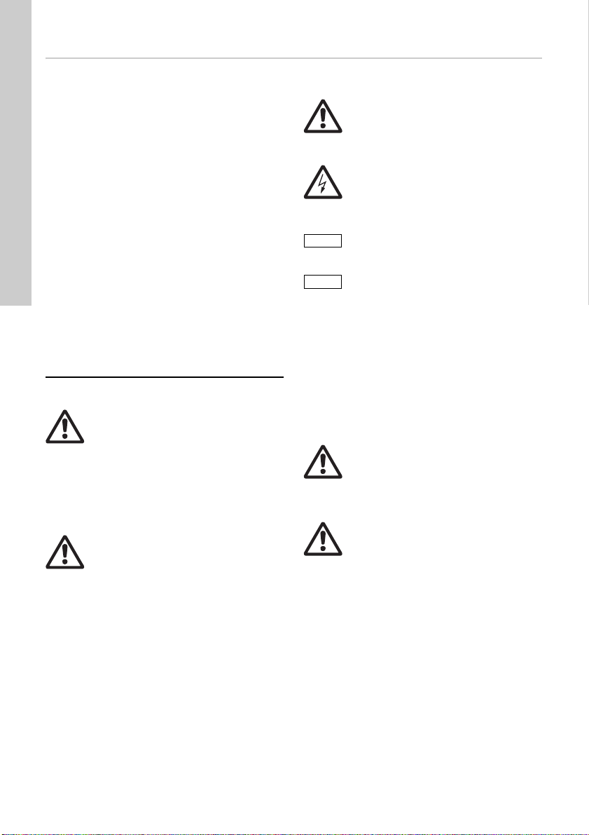
Caution
Note
English (GB)
Original installation and operating instructions.
CONTENTS
Page
1. Symbols used in this document
2. Applications
3. Product description
3.1 General construction
3.2 Description of function
3.3 Technical data
4. Transport and storage
5. Installation
5.1 Mechanical installation
5.2 Electrical installation
6. Startup
7. Operation
8. Taking the product out of operation
9. Maintenance
10. Fault finding
11. Service, spare parts, accessories
12. Disposal
Warning
Prior to installation, read these
installation and operating instructions.
Installation and operation must comply
with local regulations and accepted
codes of good practice.
Warning
This product can be used by children
of eight years and up and persons with
reduced physical, sensory or mental
capabilities or lack of experience and
knowledge if they are under
supervision or have been instructed in
the safe use of the product and
understand the hazards involved.
Children must not play with the
product. Cleaning and maintenance of
the product must not be made by
children without supervision.
1. Symbols used in this document
Warning
If these safety instructions are not
4
4
5
5
6
6
6
7
7
7
8
8
8
2. Applications
8
The level controller described in these installation
9
and operating instructions is used for
9
level-dependent on/off switching of grey wastewater
pumps. The level controller is primarily used where
9
the levels of conductive, non-flammable liquids in
tanks or pits must be strictly maintained, or where
these liquids require very shallow pumping.
observed, it may result in personal
injury.
Warning
If these instructions are not observed,
it may lead to electric shock with
consequent risk of serious personal
injury or death.
If these safety instructions are not
observed, it may result in malfunction
or damage to the equipment.
Notes or instructions that make the job
easier and ensure safe operation.
Warning
The level controller must only be used
for the applications mentioned in this
manual. Other applications are
considered as non-approved. No
liability is accepted for resulting
damages. The risk is borne solely by
the operator.
Warning
Use in explosion protection zones is
not permitted.
4
Page 5
3. Product description
1
5
4
3
6
2
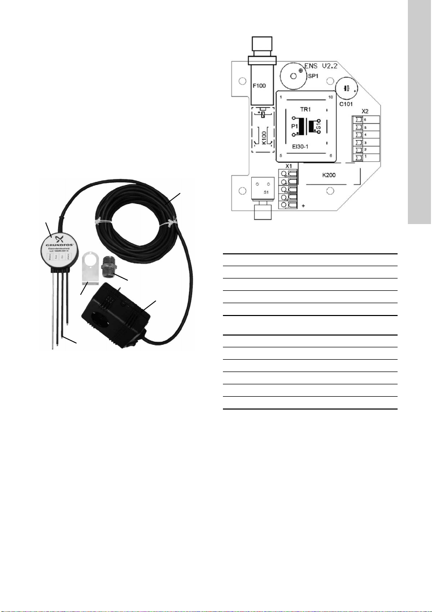
3.1 General construction
The level controller consists of four stainless steel
rod electrodes (pos. 1) (300, 600 or 1000 mm long)
in an electrode bracket (pos. 2), a mounting bracket
(pos. 3), 10 m cable (pos. 4), a plug-in control box
(pos. 5) and a 1 1/4" barrel nipple (pos. 6) for fixing
the sheet steel angle to the discharge port of
UNILIFT KP. See fig. 1.
The control box houses the evaluation electronics, a
safety plug and a Schuko outlet for connection to the
pump.
The control box houses the evaluation electronics, a
safety plug and a Schuko outlet for connection to the
pump.
Fig. 1 LLC 1000W level controller
Fig. 2 Terminal diagram
Contact assignment, terminal block X1
1 Emptying function (L)
2 Filling function (N)
3 Protective earth conductor
4 Plug (L)
5 Plug (N)
Contact assignment, terminal block X2
1 Long electrode (yellow/green)
TM05 3939 1812
2 Short electrode (blue)
3 Medium electrode (brown)
4 Alarm electrode (black)
5 Alarm contact, potential-free
6 Alarm contact, potential-free
English (GB)
TM05 3940 1812
5
Page 6

3.2 Description of function
English (GB)
The voltage between the electrodes is approximately
12 V DC, and the operating voltage for the pump
connection is 1 x 230 V. The four electrode rods
extend into the liquid to be pumped at differing
lengths. The longest electrode functions as a frame
electrode; the second-longest is the stop electrode,
followed by the start electrode, the shortest electrode
being the alarm electrode.
The level controller is factory-set to emptying
function. If the liquid level rises to the start electrode,
the controller switches on the pump. If the liquid level
falls below the stop electrode, the controller switches
the pump off. If the liquid reaches the alarm
electrode, a potential-free contact in the control box
closes, and the built-in buzzer will sound. The
additional potential-free changeover contact is
provided for special applications and can also be
used for an external alarm. The position of the
contacts (spring terminals) on the guide plate in the
control box is shown in fig. 2.
The function can be reversed by moving the cable
from connector X1-1 to connector X1-2, so that the
connected device turns on when the stop electrode
is reached, and turns off when the start electrode is
reached (filling function). The alarm is then triggered
when the tank to be filled is overfilled.
After installation, the level controller functions
automatically. Settings on the device must not be
adjusted.
3.3 Technical data
Designation LLC 1000W
Supply voltage: 1 x 230 V, 50 Hz, N, PE
Rated current Max. 6.0 A
Power 1000 W
Enclosure class, control
box
Enclosure class,
electrode bracket
Contact load, high-level
alarm, potential-free
Cable length 10 m
EMC noise emission
EMC noise immunity
Max. liquid temperature 55 °C
Ambient temperature 0-40 °C
Country of origin Germany
Materials
Component Material
Electrodes Stainless steel
Electrode bracket Plastic
Cable sheath Rubber
Plug housing Plastic
IP20
IP68
Max. 2 A, max. 230 V
According to EN
61000-6-3
According to EN
61000-6-2
4. Transport and storage
The level controller is delivered in appropriate
packaging and should remain packed until
installation.
The controller must be stored in a dry, cool, frost-free
space. The controller must not be exposed to direct
sunlight.
6
Page 7
5. Installation
Note
Rod electrodes
Caution
Warning
Installation and operation in a
potentially explosive environment are
not permissible.
Make sure that the power supply
cannot be accidentally switched on
during installation. We recommend that
you unplug the control box from the
socket.
The electronic connections on the
control box must not be exposed to
moisture.
5.1 Mechanical installation
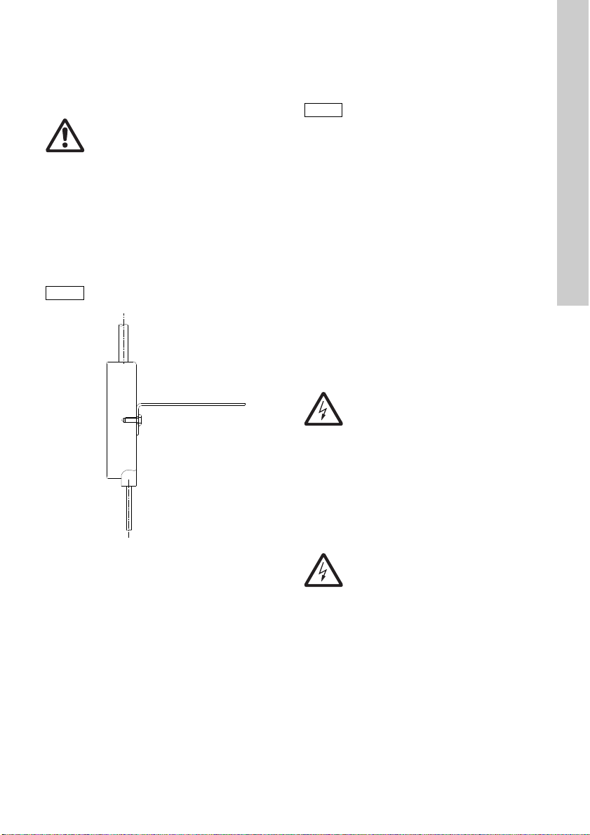
5.1.1 Mounting bracket
Attach the bracket using the two screws on the
electrode bracket. See fig. 3.
The long side must face upwards.
Fig. 3 Place the mounting bracket on the
5.1.2 Electrode bracket
The electrode bracket can either be attached directly
to the pump or to a tank wall.
The level controller can be used for Grundfos pump
types Unilift CC and Unilift KP.
The length of the electrodes must be adjusted to the
length of the pump. The difference in length between
the start and stop electrodes corresponds to the
switching differential.
electrode bracket
The control electrodes must not come
into contact with the pump or the walls
of the pump pit. The frame electrode
must be the longest electrode and may
touch the bottom.
Make sure that the pump stop point as
specified by the electrode length is
safely reached.
Make sure that the pump stop point as
specified by the electrode length is
safely reached.
It may be necessary to shorten the stop electrode. If
the electrodes are to be trimmed to change the
switching points, cut the protective tube at the
bottom end of the electrodes by approximately 5 mm
after trimming. Tighten the rod electrodes gently with
pliers prior to startup in order to prevent them from
coming loose during pump operation.
Assembly on the pump
Push the electrode bracket onto the pump pressure
outlet using the mounting bracket, so that the
electrodes face down. Then connect the electrode
bracket to the discharge port of the UNILIFT KP
using the 3-stage pressure outlet of the UNILIFT CC
supplied with the pump or using the attached 1 1/4"
barrel nipple.
5.2 Electrical installation
Warning
Connection work must be carried out
by authorised staff.
The level controller is now ready for connection.
Electrical connection work on the device itself is not
necessary if the pump is equipped with a plug.
If electrical connection work is required in order to
use certain functions or to connect the power supply
for the pump and the mains directly to the control
box, and thus not use the sockets, detach the rear
wall of the control box.
TM05 3941 1812
If the potential-free alarm contact is to be used to
forward the alarm signal to a main controller, connect
the signal cable to terminal block X2, terminals 3 and
4.
If the filling function is to be used instead of the
emptying function, move the lead from terminal X1-1
to terminal X1-2.
Warning
Make sure that the power supply
cannot be accidentally switched on
during electrical installation. We
recommend that you unplug the control
box from the socket.
English (GB)
7
Page 8

6. Startup
Note
English (GB)
Trim the electrodes to the desired
length in advance, depending on the
pump. Take into account the
technically feasible switching levels of
the pump.
After installation, plug the control box into a socket
and plug the pump plug into the control box socket.
Carry out test runs. To do so, press and hold the
switch on the control box. The level controller will not
operate when the switch is actuated. The pump runs
for as long as the button is held.
If you encounter faults during test operation, verify
that the power supply is correct, that the connected
units function properly, and that the liquid has
sufficient conductivity. See section 10. Fault finding
for more details.
If the switch on the control box is not pressed, the
level controller operates automatically.
Change over from the emptying function (delivery
state) to the filling function is described in section
5.2 Electrical installati on.
7. Operation
Once the level controller has been installed and
started up, no further action is required.
The level controller operates automatically and
switches the connected wastewater pumps on and
off based on the liquid level.
For a trial run or to briefly switch the pump on and off
during commissioning or service work, the pump can
be manually operated by pushing the switch on the
control box. See also section 6. Startup.
9. Maintenance
The level controller is maintenance-free. However,
the electrode tips must be cleaned at regular
intervals to remove any deposits that could
otherwise lead to malfunctions. The maintenance
intervals to be observed depend on the operating
conditions and the liquid pumped.
Warning
Before starting work on the product,
switch off the power supply. Make sure
that the power supply cannot be
accidentally switched on. We
recommend that you unplug the control
box from the socket.
8. Taking the product out of operation
1. Disconnect the control box from the power
supply, for instance by unplugging the control box
from the socket.
2. Unplug the pump from the pump control box, or
remove the cables from the terminals in the event
of direct connection to the pump.
3. Remove the electrode bracket from the pump.
4. Carefully wash the electrodes with clean water.
8
Page 9
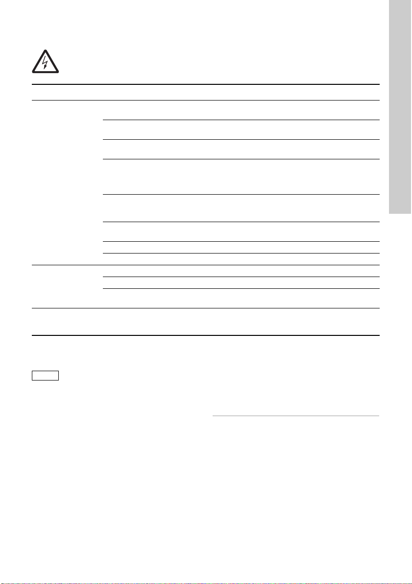
10. Fault finding
Note
Warning
Before starting work on the product, switch off the power supply. Make sure that the power
supply cannot be accidentally switched on. We recommend that you unplug the control box
from the socket.
Fault Possible cause Remedy
1. The pump does
not start.
2. The pump does
not stop.
3. Pump starts
and stops in
wrong order.
a) No power supply, or incorrect
power supply.
b) Incorrect electrical connection. Check the electrical connection and correct
c) Defective cable. Check the cable. Contact Grundfos Service
d) The motor protection of the pump
has tripped due to overheating,
blockage, voltage fault or other
pump fault.
e) Fuse in control box has blown. Replace fuse (fine-wire slow-blow fuse 8 A).
f) Controller fault or defective
electronics.
g) Electrodes contaminated. Clean the electrodes.
h) Pump defective. Replace the pump.
a) Button on the control box is stuck. Loosen the button.
b) Controller fault. Contact Grundfos Service.
c) Stop electrode too long. Trim the stop electrode. Note the minimum
a) Incorrect switching function
selected.
Check the power supply.
as needed.
in the event of a defective cable.
For actions to take when motor protection on
the pump has tripped, see the installation
and operating instructions for the pump.
If the fuse blows again immediately, identify
and remedy the cause.
Contact Grundfos Service.
possible stop point of the pump.
Move cable on terminal block X1 from
terminal 1 to terminal 2 or vice versa.
English (GB)
11. Service, spare parts, accessories
Spare parts and accessories not
supplied by Grundfos will not be
inspected or approved by Grundfos.
The use of non-authorised spare parts and
accessories voids any Grundfos warranty liability for
consequential damage.
Any malfunctions which cannot be repaired must
only be corrected by Grundfos or authorised
specialist companies.
Please provide an exact description in the event of a
malfunction to allow our service technician to
prepare and provide the appropriate spare parts.
12. Disposal
This product or parts of it must be disposed of in an
environmentally sound way:
1. Use the public or private waste collection service.
2. If this is not possible, contact the nearest
Grundfos company or service workshop.
Subject to alterations.
9
Page 10

Dansk (DK) Monterings- og driftsinstruktion
Forsigtig
Bemærk
Dansk (DK)
Oversættelse af den originale engelske udgave.
INDHOLDSFORTEGNELSE
Side
1. Symboler brugt i dette dokument
2. Anvendelse
3. Produktbeskrivelse
3.1 Generel konstruktion
3.2 Funktionsbeskrivelse
3.3 Tekniske data
4. Transport og opbevaring
5. Installation
5.1 Mekanisk installation
5.2 Elektrisk installation
6. Idriftsætning
7. Drift
8. Sådan tages produktet ud af drift
9. Vedligeholdelse
10. Fejlfinding
11. Servicering, reservedele og tilbehør
12. Bortskaffelse
Advarsel
Læs denne monterings- og drifts-
instruktion før installation. Følg lokale
forskrifter og gængs praksis ved installation og drift.
Advarsel
Dette produkt må anvendes af børn fra
8 år og personer med begrænsede fysiske, sansemæssige eller mentale evner
samt personer med manglende erfaring
med og kendskab til produktet forudsat
at de er under opsyn eller har fået klare
instrukser vedrørende sikker brug af
produktet og forstår den dermed forbundne risiko.
Børn må ikke lege med dette produkt.
Rengøring og vedligeholdelse af produktet må ikke foretages af børn uden
opsyn.
1. Symboler brugt i dette dokument
Advarsel
Hvis disse sikkerhedsanvisninger ikke
10
10
11
11
12
12
12
13
13
13
14
14
14
2. Anvendelse
14
Niveaustyringen der er beskrevet i denne monte-
15
rings- og driftsinstruktion, er beregnet til niveauaf-
15
hængig start/stop af pumper til gråt spildevand.
Niveaustyringen anvendes primært til applikationer
15
hvor niveauet af ledende, ikke-brandbare væsker i
beholdere eller brønde kræver regulering, eller hvor
sådanne væsker kræver en meget lav pumpehøjde.
overholdes, kan det medføre personskade.
Advarsel
Hvis disse anvisninger ikke overhol-
des, kan det medføre elektrisk stød
med deraf følgende risiko for alvorlig
personskade eller død.
Hvis disse sikkerhedsanvisninger ikke
overholdes, kan det medføre funktionsfejl eller skade på materiellet.
Råd og anvisninger som letter arbejdet
og sikrer pålidelig drift.
Advarsel
Niveaustyringen må kun anvendes til
de formål der er nævnt i denne manual.
Andre anvendelsesformål betragtes
som ikke godkendte. Grundfos kan ikke
holdes ansvarlig for resulterende skader. Risikoen påhviler alene operatøren.
Advarsel
Anvendelse i eksplosionsbeskyttelses-
zoner er ikke tilladt.
10
Page 11

3. Produktbeskrivelse
1
5
4
3
6
2
3.1 Generel konstruktion
Niveaustyringen består af fire stavelektroder i rustfrit
stål (pos. 1) (300, 600 eller 1000 mm længde) i en
elektrodekonsol (pos. 2), en monteringskonsol (pos.
3), 10 m kabel (pos. 4), en indstikskontrolboks (pos.
5) og et 1 1/4" nippelrør (pos. 6) til fastgørelse af pladestålvinklen til afgangsstudsen på UNILIFT KP. Se
fig. 1.
Kontrolboksen indeholder evalueringselektronik, et
sikkerhedsstik og en Schuko-udgang for tilslutning til
pumpen.
Fig. 1 LLC 1000W-niveaustyring
Fig. 2 Klemrækkediagram
Kontaktildeling, klemrække X1
1 Tømmefunktion (L)
2 Påfyldningsfunktion (N)
3 Beskyttelsesjordleder
4Stik (L)
5Stik (N)
TM05 3939 1812
Kontaktildeling, klemrække X2
1 Lang elektrode (gul/grøn)
2 Kort elektrode (blå)
3 Mellemlang elektrode (brun)
4 Alarmelektrode (sort)
5 Alarmkontakt, potentialfri
6 Alarmkontakt, potentialfri
Dansk (DK)
TM05 3940 1812
11
Page 12

3.2 Funktionsbeskrivelse
Dansk (DK)
Spændingen mellem elektroderne er ca. 12 VDC, og
pumpetilslutningen har en driftsspænding på 1 x 230
V. De fire stavelektroder nedsænkes i mediet til
pumpning i forskellige længder. Den længste elektrode fungerer som rammeelektrode, den næstlængste er stopelektroden, efterfulgt af startelektroden,
og den korteste elektrode er alarmelektroden.
Niveaustyringen er fabriksindstillet til tømmefunktion.
Hvis væskeniveauet stiger til startelektroden, tændes pumpen af styringen. Hvis væskeniveauet falder
under stopelektroden, afbrydes pumpen af styringen.
Hvis væskeniveauet når alarmelektroden, slutter en
potentialfri kontakt i kontrolboksen, og den indbyggede summer udløses. Den ekstra potentialfrie skiftekontakt er monteret til særlige formål og kan også
anvendes til en ekstern alarm. Kontakternes placering (fjederterminaler) på ledepladen i kontrolboksen
er vist i fig. 2.
Funktionen kan vendes om ved at flytte kablet fra
konnektor X1-1 til konnektor X1-2, så den tilsluttede
enhed tændes når stopelektroden nås, og slukkes
når startelektroden nås (påfyldningsfunktion). Herefter udløses alarmen når beholderen er overfyldt.
Efter installationen fungerer niveaustyringen automatisk. Enhedens indstillinger bør ikke justeres.
3.3 Tekniske data
Betegnelse LLC 1000W
Forsyningsspænding 1 x 230 V, 50 Hz, N, PE
Nominel strøm Maks. 6,0 A
Effekt 1000 W
Kapslingsklasse,
kontrolboks
Kapslingsklasse,
elektrodekonsol
Kontaktbelastning,
højvandsalarm,
potentialfri
Kabellængde 10 m
EMC-støjemission
EMC-støjimmunitet
Maks. medietemperatur 55 °C
Omgivelsestemperatur 0-40 °C
Oprindelsesland Tyskland
Materialer
Komponent Materiale
Elektroder Rustfrit stål
Elektrodekonsol Plast
Kabelkappe Gummi
Stikhus Plast
IP20
IP68
Maks. 2 A, maks. 230 V
I henhold til EN
61000-6-3
I henhold til EN
61000-6-2
12
4. Transport og opbevaring
Niveaustyringen leveres i passende emballage og
skal først pakkes ud ved installationen.
Styringen skal opbevares tørt, køligt og frostfrit. Styringen må ikke udsættes for direkte sollys.
Page 13

5. Installation
Bemærk
Stavelektroder
Forsigtig
Advarsel
Installation og drift i eksplosionsfarlige
driftsmiljøer er ikke tilladt.
Sørg for at strømforsyningen ikke ufor-
varende kan genindkobles under installationen. Vi anbefaler at kontrolboksen
fjernes fra stikkontakten.
Kontrolboksens elektroniske forbindelser må ikke udsættes for fugt.
5.1 Mekanisk installation
5.1.1 Monteringsbeslag
Fastgør beslaget med de to skruer på elektrodekonsollen. Se fig. 3.
Den lange side skal vende opad.
Fig. 3 Placér monteringsbeslaget på elektrode-
5.1.2 Elektrodekonsol
Elektrodekonsollen kan fastgøres enten direkte på
pumpen eller på en beholdervæg.
Niveaustyringen kan anvendes til Grundfos-pumpetyperne Unilift CC og Unilift KP.
Elektrodernes længde skal tilpasses efter pumpens
længde. Aktiveringsdifferencen mellem start- og stopelektroderne svarer til skiftedifferensen.
konsollen
Kontrolelektroderne må ikke komme i
kontakt med pumpen eller pumpebrøndens vægge. Rammeelektroden skal
være den længste elektrode og må
godt berøre bunden.
Sørg for at pumpens stoppunkt som
specificeret af elektrodelængden nås
sikkert.
Det kan være nødvendigt at afkorte stopelektroden.
Hvis det er nødvendigt at afkorte elektroderne for at
ændre aktiveringspunkterne, skal beskyttelsesrøret
beskæres ca. 5 mm ved bunden af elektroderne efter
afkortning. Spænd forsigtigt stavelektroderne med
tang inden opstart for at forhindre at de løsnes under
pumpedrift.
Samling på pumpen
Skub elektrodekonsollen fast på pumpens trykafgang med monteringsbeslaget så elektroderne vender nedad. Slut derefter elektrodekonsollen til
afgangsstudsen på UNILIFT KP med 3-trins trykafgangen på UNILIFT CC der følger med pumpen,
eller ved hjælp af det tilsluttede 1 1/4" nippelrør.
5.2 Elektrisk installation
Advarsel
Tilslutningen skal udføres af autorise-
ret personale.
Nu er niveaustyringen klar til tilslutning. Det er ikke
nødvendigt at foretage eltilslutning på selve enheden
hvis pumpen er forsynet med et stik.
Hvis eltilslutning er nødvendig for at bruge bestemte
funktioner eller tilslutte spændingsforsyningen til
pumpen og nettet direkte til kontrolboksen for derved
at undgå at bruge stikkene, skal kontrolboksens bagvæg afmonteres.
TM05 3941 1812
Hvis den potentialfrie alarmkontakt skal bruges til at
viderestille alarmsignalet til en hovedstyring, skal
signalkablet sluttes til klemrække X2, klemme 3 og 4.
Hvis påfyldningsfunktionen skal bruges i stedet for
tømmefunktionen, skal lederen flyttes fra klemme
X1-1 til klemme X1-2.
Advarsel
Sørg for at strømforsyningen ikke ufor-
varende kan genindkobles under den
elektriske installation. Vi a nbefaler at
kontrolboksen fjernes fra stikkontakten.
Dansk (DK)
13
Page 14

6. Idriftsætning
Bemærk
Dansk (DK)
Afkort på forhånd elektroderne til den
ønskede længde, afhængig af pumpen.
Tag højde for pumpens teknisk mulige
aktiveringsniveauer.
Forbind kontrolboksen med en stikkontakt efter
installationen, og sæt pumpens stik i kontakten på
kontrolboksen.
Udfør testkørsler. Dette gøres ved at holde kontakten på kontrolboksen nede. Niveaustyringen fungerer kun når kontakten aktiveres. Pumpen kører så
længe knappen holdes nede.
Hvis der opstår fejl under testkørslen, kontrollér at
spændingsforsyningen er korrekt, at de tilsluttede
enheder fungerer korrekt og at mediets ledningsevne
er tilstrækkelig. Se yderligere oplysninger i afsnit
10. Fejlfinding.
Hvis kontakten på kontrolboksen ikke er trykket ned,
kører niveaustyringen automatisk.
Skift fra tømmefunktionen (leveringstilstand) til
påfyldningsfunktion er beskrevet i afsnit 5.2 Elektrisk
installation.
7. Drift
Når niveaustyringen er installeret og startet op, er
det ikke nødvendigt at foretage sig yderligere.
Niveaustyringen fungerer automatisk og slutter de tilsluttede spildevandspumper til og fra, afhængigt af
væskeniveauet.
Pumpen kan betjenes manuelt ved at trykke på kontakten på kontrolboksen til brug ved prøvekørsel
eller for at slå pumpen kortvarigt til eller fra under
idriftsætning eller servicearbejde. Se også afsnit
6. Idriftsætning.
9. Vedligeholdelse
Niveaustyringen er vedligeholdelsesfri. Elektrodespidserne skal dog rengøres regelmæssigt for at
fjerne eventuelle aflejringer der kan medføre funktionsfejl. Hvilke vedligeholdelsesintervaller der skal
overholdes, afhænger af driftsforholdene og pumpemediet.
Advarsel
Afbryd strømforsyningen før du f oreta-
ger arbejde på produktet. Sørg for at
strømforsyningen ikke uforvarende kan
genindkobles. Vi anbefaler at kontrolboksen fjernes fra stikkontakten.
8. Sådan tages produktet ud af drift
Fortsæt på følgende måde for at tage LLC
1000W-niveaustyringen ud af drift:
1. Afbryd spændingsforsyningen til kontrolboksen
f.eks. ved at tage kontrolboksens stik ud af kontakten.
2. Afbryd forbindelsen fra pumpens kontrolboks til
pumpen, eller fjern kablerne fra klemmerne i tilfælde af direkte forbindelse til pumpen.
3. Afmontér elektrodekonsollen fra pumpen.
4. Skyl forsigtigt elektroderne med rent vand.
14
Page 15

10. Fejlfinding
Bemærk
Advarsel
Afbryd strømforsyningen før du foretager arbejde på produktet. Sørg for at strømforsyningen
ikke uforvarende kan genindkobles. Vi anbefaler at kontrolboksen fjernes fra stikkontakten.
Fejl Mulig årsag Afhjælpning
1. Pumpen starter
ikke.
2. Pumpen stopper ikke.
3. Pumpen starter
og stopper i den
forkerte rækkefølge.
a) Ingen forsyningsspænding eller for-
kert forsyningsspænding.
b) Forkert eltilslutning. Kontrollér eltilslutningen, og ret eventuelle
c) Kablet er defekt. Kontrollér kablet. Kontakt Grundfos Service
d) Motorbeskyttelsen på pumpen er
udløst på grund af overophedning,
blokering, spændingsfejl eller
anden pumpefejl.
e) Sikringen i kontrolboksen er
brændt.
f) Fejl i styring eller defekt elektronik. Kontakt Grundfos Service.
g) Elektroderne er snavsede. Rens elektroderne.
h) Pumpen er defekt. Udskift pumpen.
a) Knappen på kontrolboksen sidder
fast.
b) Fejl i styring. Kontakt Grundfos Service.
c) Stopelektroden er for lang. Afkort stopelektroden. Bemærk pumpens
a) Forkert skiftefunktion valgt.
Kontrollér forsyningsspændingen.
fejl.
i tilfælde af et defekt kabel.
For handlinger i tilfælde af udløsning af
motorbeskyttelsen på pumpen henvises til
pumpens monterings- og driftsinstruktion.
Udskift sikringen (træg finsikring 8 A). Hvis
sikringen brænder igen med det samme,
skal årsagen identificeres og afhjælpes.
Frigør knappen.
mulige minimumsstoppunkt.
Flyt kablet på klemrække X1 fra klemme 1
til klemme 2 eller omvendt.
Dansk (DK)
11. Servicering, reservedele og tilbehør
Reservedele og tilbehør som ikke er
leveret af Grundfos, vil ikke blive efterset eller godkendt af Grundfos.
Ved brug af ikke-godkendte reservedele og tilbehør
bortfalder enhver Grundfos-garantidækning af følgeskader.
Fejlfunktioner som ikke kan repareres, må kun
udbedres af Grundfos eller autoriserede specialistfirmaer.
Giv en nøjagtig beskrivelse i tilfælde af fejlfunktion
så vores servicetekniker kan forberede sig og skaffe
de korrekte reservedele.
12. Bortskaffelse
Dette produkt eller dele deraf skal bortskaffes på
en miljørigtig måde:
1. Brug de offentlige eller godkendte, private
renovationsordninger.
2. Hvis det ikke er muligt, kontakt nærmeste
Grundfos-selskab eller -serviceværksted.
Ret til ændringer forbeholdes.
15
Page 16

Deutsch (DE) Montage- und Betriebsanleitung
Achtung
Hinweis
Deutsch (DE)
Übersetzung des englischen Originaldokuments.
INHALTSVERZEICHNIS
Seite
1. Verwendete Symbole
2. Verwendungszweck
3. Produktbeschreibung
3.1 Allgemeiner Aufbau
3.2 Funktionsbeschreibung
3.3 Technische Daten
4. Transport und Lagerung
5. Installation
5.1 Montage
5.2 Elektrischer Anschluss
6. Inbetriebnahme
7. Betrieb
8. Außerbetriebnahme
9. Wartung
10. Störungsübersicht
11. Service, Ersatzteile, Zubehör
12. Gewährleistung
13. Entsorgung
Warnung
Lesen Sie diese Montage- und
Betriebsanleitung vor der Montage.
Montage und Betrieb müssen nach den
örtlichen Vorschriften und den anerkannten Regeln der Technik erfolgen.
Warnung
Dieses Produkt kann von Kindern ab
acht Jahren und Personen mit eingeschränkten körperlichen, sensorischen oder geistigen Fähigkeiten
sowie von Personen mit mangelnden
Erfahrungen und Kenntnissen verwendet werden, wenn sie dabei beaufsichtigt werden oder in die sichere Nutzung
des Produktes eingewiesen wurden
und die damit verbundenen Gefahren
verstehen.
Kinder dürfen dieses Produkt nicht als
Spielzeug verwenden. Kinder dürfen
dieses Produkt nicht unbeaufsichtigt
reinigen oder warten.
16
16
17
17
18
18
18
19
19
19
20
20
20
20
21
21
21
21
1. Verwendete Symbole
Warnung
Die Nichtbeachtung dieser Sicherheits-
hinweise kann zu Personenschäden
führen.
Warnung
Die Nichtbeachtung dieser Sicherheits-
hinweise kann zum elektrischen Schlag
führen, der schwere Personenschäden
oder den Tod zur Folge haben kann.
Die Nichtbeachtung dieser Sicherheitshinweise kann Fehlfunktionen oder
Sachschäden zur Folge haben.
Hinweise oder Anweisungen, die das
Arbeiten erleichtern und einen sicheren
Betrieb gewährleisten.
2. Verwendungszweck
Die in der vorliegenden Betriebsanleitung beschriebene elektronische Niveausteuerung dient zum
niveauabhängigen Ein- und Ausschalten von
Schmutzwasserpumpen für Grauwasser. Sie wird vor
allem dort eingesetzt, wo Füllstände leitfähiger,
nichtbrennbarer Medien in Behältern oder Gruben
entweder sehr genau eingehalten werden müssen
oder diese Flüssigkeiten sehr flach abgepumpt werden sollen.
Warnung
Die Niveausteuerungen dürfen nur für
den hier angegebenen Verwendungszweck eingesetzt werden. Jeder darüber hinaus gehende Gebrauch gilt als
nicht bestimmungsgemäß. Für daraus
entstehende Schäden wird keine Haftung übernommen. Das Risiko hierfür
trägt allein der Betreiber.
Warnung
Die Verwendung in Ex-S chutz-Zonen ist
nicht zulässig.
16
Page 17

3. Produktbeschreibung
1
5
4
3
6
2
3.1 Allgemeiner Aufbau
Die elektronische Niveausteuerung besteht aus 4
(im Auslieferzustand durchgehend 300 mm langen)
Edelstahlelektroden (Pos. 1) im Elektrodenhalter
(Pos. 2), Befestigungswinkel (Pos. 3), 10 m Kabel
(Pos. 4), Steckerschaltgerät (Pos. 5), siehe Abb. 1,
sowie 1 1/4" Doppelnippel (Pos. 6) zur Fixierung des
Blechwinkels am Druckstutzen der UNILIFT KP.
Im Steckerschaltgerät befinden sich die Auswerteelektronik ein Schutzkontaktstecker und eine Schutzkontaktsteckdose zum Anschluss der Pumpe.
Abb. 1 Elektronische Niveausteuerung
LLC 1000W
Der Klemmenbelegungsplan ist in Abb. 2 dargestellt.
Abb. 2 Klemmenbelegungsplan
Kontaktbelegung Klemmenleiste X1
1 Pumpe Funktion Leeren (L)
2 Pumpe Funktion Füllen (N)
3 Erde Schutzleiter
4Stecker (L)
TM05 3939 1812
5Stecker (N)
Kontaktbelegung Klemmenleiste X2
1 Elektrode lang (gelb/grün)
2 Elektrode kurz (blau)
3 Elektrode mittel (braun)
4 Elektrode Alarm (schwarz)
5 Alarmkontakt, potentialfrei
6 Alarmkontakt, potentialfrei
Deutsch (DE)
TM05 3940 1812
17
Page 18

3.2 Funktionsbeschreibung
Deutsch (DE)
Die Elektrodenspannung zwischen den Elektroden
beträgt ca. 12 V Gleichspannung und die Arbeitsspannung für den Pumpenanschluss 1 x 230 V.
Die vier Elektrodenstäbe ragen unterschiedlich lang
in die leitende Flüssigkeit. Die längste Elektrode fungiert als Masseelektrode, die nächste (in der Länge
abnehmend) ist die Ausschaltelektrode dann kommt
die Einschaltelektrode und die kürzeste ist die Alarmelektrode.
Die elektronische Niveausteuerung ist werkseitig auf
die Funktion "Leeren" eingestellt. Steigt der Flüssigkeitsspiegel bis zur Einschaltelektrode an, schaltet
die Steuerung die angeschlossene Pumpe ein.
Unterschreitet der Flüssigkeitsstand die Ausschaltelektrode, so schaltet die Steuerung die Pumpe ab.
Wird die Alarmelektrode von der Flüssigkeit erreicht,
so schließt im Schaltgerät ein potentialfreier Kontakt
und der eingebaute Summer ertönt. Der zusätzliche
potentialfreie Wechselkontakt ist für Sonderanwendungen vorgesehen und kann auch für eine externe
Alarmierung genutzt werden. Die Lage der Kontakte
(Federklemmen) auf der Leiterplatte im Schaltgerät
ist in Abb. 2 dargestellt.
Durch einen Wechsel des Kabels vom Anschluss
X1-1 auf den Anschluss X1-2 kann die Funktion
umgekehrt werden, so dass das angeschlossene
Gerät bei Erreichen der AUS-Elektrode einschaltet
und bei Erreichen der EIN-Elektrode abschaltet
(Funktion "Füllen"). Der Alarm wird dann ausgelöst,
wenn das zu füllende Gefäß überfüllt wird.
Nach der Installation arbeitet die elektronische
Niveausteuerung automatisch. Einstellarbeiten am
Gerät sind nicht vorzunehmen.
3.3 Technische Daten
Bezeichnung LLC 1000W
Versorgungsspannung 1 x 230 V, 50 Hz, N, PE
Nennstrom Max. 6,0 A
Leistung 1000 W
Schutzart
Steckerschaltgerät
Schutzart
Elektrodenhalter
Max. Kontaktbelastung
Hochwasseralarm
potentialfrei
Kabellänge 10 m
EMV-Störemmission gemäß EN 61000-6-3
EMV-Störfestigkeit gemäß EN 61000-6-2
Max. Medientemperatur 55 °C
Umgebungstemperatur 0-40 °C
Ursprungsland Deutschland
Werkstoffe
Komponente Werkstoff
Elektroden Edelstahl
Elektrodenhalter Kunststoff
Kabelmantel Gummi
Steckergehäuse Kunststoff
IP20
IP68
Max. 2 A, max. 230 V
18
4. Transport und Lagerung
Die elektronische Niveausteuerung wird in einer
zweckmäßigen Verpackung geliefert, in der sie bis
zur Installation auch verbleiben sollte.
Die Lagerung der Steuerung darf nur an einem trockenen, kühlen aber frostfreien Raum erfolgen.
Die Steuerung darf keinem direkten Sonnenlicht ausgesetzt werden.
Page 19

5. Installation
Hinweis
Stabelektroden
Achtung
Warnung
Die Montage und der Betrieb in einer
explosionsgefährdeten Umgebung sind
nicht zulässig.
Die Steuerung muss in Übereinstimmung mit den örtlichen Vorschriften
montiert und angeschlossen werden.
Vor sämtlichen Montagearbeiten ist die
Spannungsversorgung zur Niveausteuerung zu unterbrechen und gegen versehentliches Wiedereinschalten zu
sichern.
Die elektrischen Anschlüsse des Steckerschaltgerätes dürfen keiner Feuchtigkeit ausgesetzt werden.
5.1 Montage
5.1.1 Befestigungswinkel montieren
Den beiliegenden Winkel mit den zwei am Elektrodenhalter befindlichen Schrauben befestigen.
Siehe Abb. 3.
Der lange Schenkel muss nach oben
zeigen.
Abb. 3 Anbringen des Befestigungswinkels an
5.1.2 Elektrodenhalter montieren
Der Elektrodenhalter kann entweder direkt an der
Pumpe oder an einer Behälterwand befestigt werden.
Die Niveausteuerung ist einsetzbar für die Grundfos
Pumpenbaureihen Unilift CC und Unilift KP.
Die Länge der Elektroden beträgt standardmäßig
jeweils 300 mm. Sie sind auf die Länge der jeweiligen Pumpen anzupassen. Die Längendifferenz von
Ein- und Ausschaltelektrode entspricht der Schaltdifferenz.
den Elektrodenhalter
Die Steuerelektroden dürfen weder die
Pumpe noch die Wände des Pumpensumpfes berühren. Die Masseelektrode muss die längste Elektrode sein
und kann auf dem Boden aufstehen.
Es ist darauf zu achten, dass der durch
die Elektrodenlänge vorgegebene Ausschaltpunkt von der Pumpe auch
sicher erreicht wird.
Ggf. ist die Ausschaltelektrode zu kürzen. Sollen die
Elektroden zur Veränderung der Schaltpunkte
gekürzt werden, so ist der Schutzschlauch am unteren Ende der Elektroden nach dem Kürzen ca. 5 mm
abzuschneiden. Die Stabelektroden sind vor der
Inbetriebnahme mit einer Zange leicht festzuziehen
um ein Lösen beim Pumpbetrieb zu vermeiden.
Montage an der Pumpe
Der Elektrodenhalter wird mit Hilfe des Befestigungswinkels direkt auf den Druckabgang der Pumpe aufgeschoben, so dass die Elektroden nach unten zeigen, und anschließend mit dem 3-stufigen
Druckabgang der UNILIFT CC (im Lieferumfang der
Pumpe) oder mittels beigefügtem 1 1/4" Doppelnippel am Druckstutzen der UNILIFT KP befestigt.
5.2 Elektrischer Anschluss
Warnung
Elektrische Anschlussarbeiten dürfen
nur durch autorisiertes Fachpersonal
vorgenommen werden.
Die elektronische Niveausteuerung ist anschlussfertig montiert. Elektrische Anschlussarbeiten am Gerät
selbst müssen nicht durchgeführt werden, wenn die
Pumpe mit einem Stecker ausgestattet ist.
Sind dennoch elektrische Anschlussarbeiten erforderlich, um bestimmte Funktionen zu nutzen oder die
Spannungsversorgung für die Pumpe und den Netzanschluss direkt im Gerät unter Umgehung der
Steckdosen vorzunehmen, ist die Rückwand des
Steckerschaltgeräts abzuschrauben.
Warnung
Vor elektrischen Anschlussarbeiten ist
unbedingt das Schaltgerät von der
TM05 3941 1812
Soll der potentialfreie Alarmkontakt zur Weiterleitung
der Alarmmeldung an eine übergeordnete Steuerung
genutzt werden, ist das Signalkabel an die Klemmenleiste X2, Klemmen 3 und 4 anzuschließen.
Soll statt der Funktion "Leeren" die Funktion "Füllen"
genutzt werden, ist der Leiter von Klemme X1-1 auf
die Klemme X1-2 aufzulegen.
Spannungsversorgung zu trennen und
gegen versehentliches Einschalten zu
sichern, z.B. durch Herausziehen des
Schaltgeräts aus der Steckdose.
Deutsch (DE)
19
Page 20

6. Inbetriebnahme
Hinweis
Deutsch (DE)
Abgestimmt auf die jeweilige Pumpe
sind im Vorfeld die Elektroden auf die
richtige Länge zu kürzen. Bitte hierzu
vorher die technisch möglichen Schaltniveaus der Pumpen beachten.
Nach der ordnungsgemäßen Installation zunächst
das Schaltgerät in eine geeignete Steckdose stecken
und dann den Stecker der Pumpe in die Steckdose
des Schaltgeräts stecken.
Probeläufe durchführen. Dazu den Schalter am
Schaltgerät drücken und gedrückt halten.
Die Niveausteuerung ist bei Betätigung des
Schalters nicht wirksam. Die Pumpe läuft, solange
der Taster betätigt wird.
Sollten während des Probebetriebs Störungen auftreten, ist zu prüfen, ob die Spannungsversorgung
korrekt bzw. die angeschlossenen Geräte einwandfrei funktionieren und die Flüssigkeit eine ausreichende Leitfähigkeit besitzt. Weitere Hinweise finden
Sie im Abschnitt 10. Störungsübersicht.
Wird der Schalter am Schaltgerät nicht gedrückt,
befindet sich die elektronische Niveausteuerung im
Automatikbetrieb.
Das Umschalten von der Funktion Leeren (Auslieferungszustand) in die Funktion Füllen ist unter
Abschnitt 5.2 Elektrischer Anschluss beschrieben.
7. Betrieb
Nachdem die elektronische Niveausteuerung ordnungsgemäß installiert und in Betrieb genommen
worden ist, ist keine weitere Bedienung erforderlich.
Die elektronische Niveausteuerung arbeitet automatisch und schaltet die angeschlossene Abwasserpumpe niveauabhängig ein und aus.
Für einen Probelauf oder kurzzeitiges Ein- oder Ausschalten der Pumpe während der Inbetriebnahme
oder Servicearbeiten kann die Pumpe durch Drücken
des Schalters am Schaltgerät manuell betrieben
werden. Siehe auch Abschnitt 6. Inbetriebnahme.
9. Wartung
Die elektronische Niveausteuerung ist wartungsfrei.
In regelmäßigen Zeitabständen sollten jedoch die
Elektrodenspitzen von möglichen Ablagerungen
gereinigt werden, da hierdurch Fehlfunktionen verursacht werden könnten. Die Intervalle sind von den
Betriebsbedingungen und dem Fördermedium
abhängig.
Warnung
Vor Wartungsarbeiten ist unbedingt
das Schaltgerät von der Spannungsversorgung zu trennen und gegen versehentliches Einschalten zu sichern
(z.B. durch Herausziehen des Schaltgeräts aus der Steckdose).
8. Außerbetriebnahme
Warnung
Elektrische Arbeiten dürfen nur durch
autorisiertes Fachpersonal vorgenommen werden.
Zur Außerbetriebnahme der elektronischen Niveauerfassung LLC 1000W ist wie folgt vorzugehen:
1. Steckerschaltgerät von der Spannungsversorgung trennen (z.B. durch Herausziehen des
Schaltgeräts aus der Steckdose).
2. Pumpenstecker aus dem Pumpenschaltgerät ziehen oder bei direktem Pumpenanschluss die
Kabel an den Klemmen entfernen.
3. Elektrodenhalter von der Pumpe demontieren.
4. Elektroden sorgfältig mit klarem Wasser reinigen.
20
Page 21

10. Störungsübersicht
Hinweis
Warnung
Vor Arbeiten an der elektronischen Niveausteuerung ist unbedingt das Schaltgerät von der
Spannungsversorgung zu trennen und gegen versehentliches Einschalten zu sichern
(z.B. durch Herausziehe n des Schaltgeräts aus der Steckdose).
Störung Mögliche Ursache Abhilfe
1. Pumpe schaltet
nicht ein.
2. Pumpe schaltet
nicht aus.
3. Pumpe schaltet in
falscher Reihenfolge ein und aus.
a) Keine oder falsche Spannungsver-
sorgung.
b) Fehlerhafter elektrischer Anschluss. Elektrischen Anschluss überprüfen und
c) Defektes Kabel. Kabel überprüfen. Bei einem defekten
d) Motorschutz an der Pumpe hat aus-
gelöst (Überhitzung, Blockierung,
Spannungsfehler oder sonstiger
Defekt an der Pumpe).
e) Sicherung im Schaltgerät durchge-
brannt.
f) Steuerungsfehler/Elektronik defekt. Bitte an den Grundfos Service wenden.
g) Elektroden verschmutzt. Elektroden reinigen.
h) Pumpe defekt. Pumpe austauschen.
a) Taster am Schaltgerät verhakt. Taster lösen.
b) Steuerungsfehler. Bitte an den Grundfos Service wenden.
c) Ausschaltelektrode zu lang. Ausschaltelektrode kürzen
a) Falsche Schaltfunktion gewählt. Kabel an der Klemmenleiste X1 von
Spannungsversorgung überprüfen.
ordnungsgemäß ausführen.
Kabel bitte an den Grundfos Service
wenden.
Maßnahmen bei Auslösen des Motorschutzes der Pumpe, siehe Montageund Betriebsanleitung der Pumpe.
Sicherung ersetzen (Feinsicherung 8 A,
träge). Bei sofortigem, erneutem Durchbrennen der Sicherung Ursache suchen
und beheben.
(minimal möglichen Ausschaltpunkt der
Pumpe beachten).
Klemme 1 auf Klemme 2 legen
(bzw. umgekehrt).
Deutsch (DE)
11. Service, Ersatzteile, Zubehör
Wir machen ausdrücklich darauf aufmerksam, dass nicht von uns gelieferte
Ersatzteile und Zubehör auch nicht von
uns geprüft und freigegeben sind.
Für Schäden, die durch die Verwendung von nicht
Original-Ersatzteilen und Zubehör entstehen ist jede
Haftung und Gewährleistung ausgeschlossen.
Störungen, die nicht selbst behoben werden können,
sollten nur vom Grundfos Service oder autorisierten
Fachfirmen beseitigt werden.
Bitte geben Sie eine genaue Schilderung im Fall
einer Störung, damit sich unser Service-Techniker
vorbereiten und mit den entsprechenden Ersatzteilen
ausrüsten kann.
12. Gewährleistung
Die Gewährleistung erfolgt im Rahmen unserer allgemeinen Lieferbedingungen. Von der Haftung ausgenommen sind Schäden, die auf Fehler beim Einbau, dem elektrischen Anschluss oder auf falsche
Verwendung zurückzuführen sind. Für Folgeschäden
wird nicht gehaftet. Der Gewährleistungsbeginn ist
nachzuweisen.
13. Entsorgung
Dieses Produkt sowie Teile davon müssen umweltgerecht entsorgt werden:
1. Nutzen Sie die öffentlichen oder privaten
Entsorgungsgesellschaften.
2. Ist das nicht möglich, wenden Sie sich bitte an
die nächste Grundfos Gesellschaft oder Werkstatt.
Technische Änderungen vorbehalten.
21
Page 22

Declaration of conformity
Declaration of conformity 1
GB: EC declaration of conformity
We, Grundfos, declare under our sole responsibility that the product LLC
1000W, to which this declaration relates, is in conformity with these
Council directives on the approximation of the laws of the EC member
states:
DE: EG-Konformitätserklärung
Wir, Grundfos, erklären in alleiniger Verantwortung, dass das Produkt
LLC 1000W, auf das sich diese Erklärung bezieht, mit den folgenden
Richtlinien des Rates zur Angleichung der Rechtsvorschriften der
EU-Mitgliedsstaaten übereinstimmt:
– Low Voltage Directive (2006/95/EC)*.
Standard used: EN 60335-1:2002 and EN 60204-1:2006.
– EMC Directive (2004/108/EC).
Standards used: EN 61000-6-2:2005 and EN 61000-6-3:2007.
* Only for products with operating voltage > 50 VAC or > 75 VDC.
This EC declaration of conformity is only valid when published as part of
the Grundfos installation and operating instructions (publication number
98335640 0315).
DK: EF-overensstemmelseserklæring
Vi, Grundfos, erklærer under ansvar at produktet LLC 1000W som denne
erklæring omhandler, er i overensstemmelse med disse af Rådets
direktiver om indbyrdes tilnærmelse til EF-medlemsstaternes lovgivning:
Székesfehérvár, 17 April 2013
Jannek Uldal Christesen
D&E Central Europe
Site Manager
Grundfos Hungary Ltd.
Ipari Park
Búzavirág u. 14
2890 Tatabánya, Hungary
Person authorised to compile technical file and
empowered to sign the EC declaration of conformity.
22
Page 23

232425
Page 24

Page 25

Page 26

Argentina
Grundfos companies
Bombas GRUNDFOS de Argentina S.A.
Ruta Panamericana km. 37.500 Centro
Industrial Garin
1619 Garín Pcia. de B.A.
Phone: +54-3327 414 444
Telefax: +54-3327 45 3190
Australia
GRUNDFOS Pumps Pty. Ltd.
P.O. Box 2040
Regency Park
South Australia 5942
Phone: +61-8-8461-4611
Telefax: +61-8-8340 0155
Austria
GRUNDFOS Pumpen Vertrieb
Ges.m.b.H.
Grundfosstraße 2
A-5082 Grödig/Salzburg
Tel.: +43-6246-883-0
Telefax: +43-6246-883-30
Belgium
N.V. GRUNDFOS Bellux S.A.
Boomsesteenweg 81-83
B-2630 Aartselaar
Tél.: +32-3-870 7300
Télécopie: +32-3-870 7301
Belarus
Представительство ГРУНДФОС в
Минске
220125, Минск
ул. Шафарнянская, 11, оф. 56, БЦ
«Порт»
Тел.: +7 (375 17) 286 39 72/73
Факс: +7 (375 17) 286 39 71
E-mail: minsk@grundfos.com
Bosna and Herzegovina
GRUNDFOS Sarajevo
Zmaja od Bosne 7-7A,
BH-71000 Sarajevo
Phone: +387 33 592 480
Telefax: +387 33 590 465
www.ba.grundfos.com
e-mail: grundfos@bih.net.ba
Brazil
BOMBAS GRUNDFOS DO BRASIL
Av. Humberto de Alencar Castelo
Branco, 630
CEP 09850 - 300
São Bernardo do Campo - SP
Phone: +55-11 4393 5533
Telefax: +55-11 4343 5015
Bulgaria
Grundfos Bulgaria EOOD
Slatina District
Iztochna Tangenta street no. 100
BG - 1592 Sofia
Tel. +359 2 49 22 200
Fax. +359 2 49 22 201
email: bulgaria@grundfos.bg
Canada
GRUNDFOS Canada Inc.
2941 Brighton Road
Oakville, Ontario
L6H 6C9
Phone: +1-905 829 9533
Telefax: +1-905 829 9512
China
GRUNDFOS Pumps (Shanghai) Co. Ltd.
10F The Hub, No. 33 Suhong Road
Minhang District
Shanghai 201106
PRC
Phone: +86 21 612 252 22
Telefax: +86 21 612 253 33
Croatia
GRUNDFOS CROATIA d.o.o.
Buzinski prilaz 38, Buzin
HR-10010 Zagreb
Phone: +385 1 6595 400
Telefax: +385 1 6595 499
www.hr.grundfos.com
Czech Republic
GRUNDFOS s.r.o.
Čajkovského 21
779 00 Olomouc
Phone: +420-585-716 111
Telefax: +420-585-716 299
Denmark
GRUNDFOS DK A/S
Martin Bachs Vej 3
DK-8850 Bjerringbro
Tlf.: +45-87 50 50 50
Telefax: +45-87 50 51 51
E-mail: info_GDK@grundfos.com
www.grundfos.com/DK
Estonia
GRUNDFOS Pumps Eesti OÜ
Peterburi tee 92G
11415 Tallinn
Tel: + 372 606 1690
Fax: + 372 606 1691
Finland
OY GRUNDFOS Pumput AB
Mestarintie 11
FIN-01730 Vantaa
Phone: +358-(0)207 889 900
Telefax: +358-(0)207 889 550
France
Pompes GRUNDFOS Distribution S.A.
Parc d’Activités de Chesnes
57, rue de Malacombe
F-38290 St. Quentin Fallavier (Lyon)
Tél.: +33-4 74 82 15 15
Télécopie: +33-4 74 94 10 51
Germany
GRUNDFOS GMBH
Schlüterstr. 33
40699 Erkrath
Tel.: +49-(0) 211 929 69-0
Telefax: +49-(0) 211 929 69-3799
e-mail: infoservice@grundfos.de
Service in Deutschland:
e-mail: kundendienst@grundfos.de
HILGE GmbH & Co. KG
Hilgestrasse 37-47
55292 Bodenheim/Rhein
Germany
Tel.: +49 6135 75-0
Telefax: +49 6135 1737
e-mail: hilge@hilge.de
Greece
GRUNDFOS Hellas A.E.B.E.
20th km. Athinon-Markopoulou Av.
P.O. Box 71
GR-19002 Peania
Phone: +0030-210-66 83 400
Telefax: +0030-210-66 46 273
Hong Kong
GRUNDFOS Pumps (Hong Kong) Ltd.
Unit 1, Ground floor
Siu Wai Industrial Centre
29-33 Wing Hong Street &
68 King Lam Street, Cheung Sha Wan
Kowloon
Phone: +852-27861706 / 27861741
Telefax: +852-27858664
Hungary
GRUNDFOS Hungária Kft.
Park u. 8
H-2045 Törökbálint,
Phone: +36-23 511 110
Telefax: +36-23 511 111
India
GRUNDFOS Pumps India Private
Limited
118 Old Mahabalipuram Road
Thoraipakkam
Chennai 600 096
Phone: +91-44 2496 6800
Indonesia
PT GRUNDFOS Pompa
Jl. Rawa Sumur III, Blok III / CC-1
Kawasan Industri, Pulogadung
Jakarta 13930
Phone: +62-21-460 6909
Telefax: +62-21-460 6910 / 460 6901
Ireland
GRUNDFOS (Ireland) Ltd.
Unit A, Merrywell Business Park
Ballymount Road Lower
Dublin 12
Phone: +353-1-4089 800
Telefax: +353-1-4089 830
Italy
GRUNDFOS Pompe Italia S.r.l.
Via Gran Sasso 4
I-20060 Truccazzano (Milano)
Tel.: +39-02-95838112
Telefax: +39-02-95309290 / 95838461
Japan
GRUNDFOS Pumps K.K.
Gotanda Metalion Bldg., 5F,
5-21-15, Higashi-gotanda
Shiagawa-ku, Tokyo
141-0022 Japan
Phone: +81 35 448 1391
Telefax: +81 35 448 9619
Korea
GRUNDFOS Pumps Korea Ltd.
6th Floor, Aju Building 679-5
Yeoksam-dong, Kangnam-ku, 135-916
Seoul, Korea
Phone: +82-2-5317 600
Telefax: +82-2-5633 725
Latvia
SIA GRUNDFOS Pumps Latvia
Deglava biznesa centrs
Augusta Deglava ielā 60, LV-1035, Rīga,
Tālr.: + 371 714 9640, 7 149 641
Fakss: + 371 914 9646
Lithuania
GRUNDFOS Pumps UAB
Smolensko g. 6
LT-03201 Vilnius
Tel: + 370 52 395 430
Fax: + 370 52 395 431
Page 27

Malaysia
GRUNDFOS Pumps Sdn. Bhd.
7 Jalan Peguam U1/25
Glenmarie Industrial Park
40150 Shah Alam
Selangor
Phone: +60-3-5569 2922
Telefax: +60-3-5569 2866
Mexico
Bombas GRUNDFOS de México S.A. de
C.V.
Boulevard TLC No. 15
Parque Industrial Stiva Aeropuerto
Apodaca, N.L. 66600
Phone: +52-81-8144 4000
Telefax: +52-81-8144 4010
Netherlands
GRUNDFOS Netherlands
Veluwezoom 35
1326 AE Almere
Postbus 22015
1302 CA ALMERE
Tel.: +31-88-478 6336
Telefax: +31-88-478 6332
E-mail: info_gnl@grundfos.com
New Zealand
GRUNDFOS Pumps NZ Ltd.
17 Beatrice Tinsley Crescent
North Harbour Industrial Estate
Albany, Auckland
Phone: +64-9-415 3240
Telefax: +64-9-415 3250
Norway
GRUNDFOS Pumper A/S
Strømsveien 344
Postboks 235, Leirdal
N-1011 Oslo
Tlf.: +47-22 90 47 00
Telefax: +47-22 32 21 50
Poland
GRUNDFOS Pompy Sp. z o.o.
ul. Klonowa 23
Baranowo k. Poznania
PL-62-081 Przeźmierowo
Tel: (+48-61) 650 13 00
Fax: (+48-61) 650 13 50
Portugal
Bombas GRUNDFOS Portugal, S.A.
Rua Calvet de Magalhães, 241
Apartado 1079
P-2770-153 Paço de Arcos
Tel.: +351-21-440 76 00
Telefax: +351-21-440 76 90
Romania
GRUNDFOS Pompe România SRL
Bd. Biruintei, nr 103
Pantelimon county Ilfov
Phone: +40 21 200 4100
Telefax: +40 21 200 4101
E-mail: romania@grundfos.ro
Russia
ООО Грундф ос Россия
109544, г. Москва, ул. Школьная,
39-41, стр. 1
Тел. (+7) 495 564-88-00 (495)
737-30-00
Факс (+7) 495 564 88 11
E-mail grundfos.moscow@grundfos.com
Serbia
Grundfos Srbija d.o.o.
Omladinskih brigada 90b
11070 Novi Beograd
Phone: +381 11 2258 740
Telefax: +381 11 2281 769
www.rs.grundfos.com
Singapore
GRUNDFOS (Singapore) Pte. Ltd.
25 Jalan Tukang
Singapore 619264
Phone: +65-6681 9688
Telefax: +65-6681 9689
Slovakia
GRUNDFOS s.r.o.
Prievozská 4D
821 09 BRATISLAVA
Phona: +421 2 5020 1426
sk.grundfos.com
Slovenia
GRUNDFOS d.o.o.
Šlandrova 8b, SI-1231 Ljubljana-Črnuče
Phone: +386 31 718 808
Telefax: +386 (0)1 5680 619
E-mail: slovenia@grundfos.si
South Africa
GRUNDFOS (PTY) LTD
Corner Mountjoy and George Allen
Roads
Wilbart Ext. 2
Bedfordview 2008
Phone: (+27) 11 579 4800
Fax: (+27) 11 455 6066
E-mail: lsmart@grundfos.com
Spain
Bombas GRUNDFOS España S.A.
Camino de la Fuentecilla, s/n
E-28110 Algete (Madrid)
Tel.: +34-91-848 8800
Telefax: +34-91-628 0465
Sweden
GRUNDFOS AB
Box 333 (Lunnagårdsgatan 6)
431 24 Mölndal
Tel.: +46 31 332 23 000
Telefax: +46 31 331 94 60
Switzerland
GRUNDFOS Pumpen AG
Bruggacherstrasse 10
CH-8117 Fällanden/ZH
Tel.: +41-44-806 8111
Telefax: +41-44-806 8115
Taiwan
GRUNDFOS Pumps (Taiwan) Ltd.
7 Floor, 219 Min-Chuan Road
Taichung, Taiwan, R.O.C.
Phone: +886-4-2305 0868
Telefax: +886-4-2305 0878
Thailand
GRUNDFOS (Thailand) Ltd.
92 Chaloem Phrakiat Rama 9 Road,
Dokmai, Pravej, Bangkok 10250
Phone: +66-2-725 8999
Telefax: +66-2-725 8998
Turkey
GRUNDFOS POMPA San. ve Tic. Ltd.
Sti.
Gebze Organize Sanayi Bölgesi
Ihsan dede Caddesi,
2. yol 200. Sokak No. 204
41490 Gebze/ Kocaeli
Phone: +90 - 262-679 7979
Telefax: +90 - 262-679 7905
E-mail: satis@grundfos.com
Ukraine
Бізнес Центр Європа
Столичне шосе, 103
м. Київ, 03131, Україна
Телефон : (+38 044) 237 04 00
Факс.: (+38 044) 237 04 01
E-mail: ukraine@grundfos.com
United Arab Emirates
GRUNDFOS Gulf Distribution
P.O. Box 16768
Jebel Ali Free Zone
Dubai
Phone: +971 4 8815 166
Telefax: +971 4 8815 136
United Kingdom
GRUNDFOS Pumps Ltd.
Grovebury Road
Leighton Buzzard/Beds. LU7 4TL
Phone: +44-1525-850000
Telefax: +44-1525-850011
U.S.A.
GRUNDFOS Pumps Corporation
17100 West 118th Terrace
Olathe, Kansas 66061
Phone: +1-913-227-3400
Telefax: +1-913-227-3500
Uzbekistan
Grundfos Tashkent, Uzbekistan The Representative Office of Grundfos Kazakhstan
in Uzbekistan
38a, Oybek street, Tashkent
Телефон: (+998) 71 150 3290 / 71 150
3291
Факс: (+998) 71 150 3292
Addresses Revised 10.03.2015
Grundfos companies
Page 28

98335640 0315
ECM: 1113736
www.grundfos.com
© Copyright Grundfos Holding A/S
owned by Grundfos Holding A/S or Grundfos A/ S, Denmark. All rights reserved worldwide.
The name Grundfos, the Grundfos logo, and be think innovate are registered trademarks
 Loading...