

Page 1

GRUNDFOS INSTRUCTIONS
LFE, LCSE
End-suction, frame-mounted pumps with integrated VFD
End-suction, close-coupled, split-coupling pumps with integrated VFD
Installation and operating instructions
Page 2

LFE, LCSE
)UDQ©DLV&$
(VSD³RO0;
Table of contents
English (US)
Installation and operating instructions. . . . . . . . . . . . . . . . . . . . . . . . . . . . . . . . . . . . . . . . . . . . . . . . . . . . . . . . . . . . 3
Notice d'installation et de fonctionnement. . . . . . . . . . . . . . . . . . . . . . . . . . . . . . . . . . . . . . . . . . . . . . . . . . . . . . . . 55
Instrucciones de instalación y operación . . . . . . . . . . . . . . . . . . . . . . . . . . . . . . . . . . . . . . . . . . . . . . . . . . . . . . . 107
2
Page 3

English (US) Installation and operating instructions
Original installation and operating instructions
These installation and operating instructions describe LFE,
LCSE.
Sections 1-5 give the information necessary to be able to unpack,
install and start up the product in a safe way.
Sections 6-30 give important information about the product, as
well as information on service, fault finding and disposal of the
product.
CONTENTS
Page
1. Limited warranty
2. General information
2.1 Symbols used in this document
2.2 Other important notes
3. Receiving the product
3.1 Unpacking the product
3.2 Inspecting the product
3.3 Temporary storage after delivery
4. Installing the product
4.1 Location
4.2 Horizontal pump foundation
4.3 Securing the base plate
4.4 Mechanical installation
4.5 Electrical connections
4.6 Motors
5. Starting up the product
5.1 Priming
5.2 Pre-start checklist
5.3 Motor direction of rotation
5.4 Starting the pump
5.5 Voltage and frequency variation
6. Storing and handling the product
7. Product introduction
7.1 Applications
7.2 Pumped liquids
7.3 Pump identification
8. Servicing the product
8.1 Maintaining the product
8.2 Lubricating the product
8.3 Disassembling the pump
8.4 Replacing the shaft seal (LCSE pumps)
8.5 Replacing the wear ring
8.6 Reassembling the pump
8.7 LFE, exploded view and parts list
8.8 LCSE, exploded view and parts list
9. Taking the product out of operation
9.1 General procedure
9.2 Short-term shutdown
9.3 Long-term shutdown
10. Fault finding
11. PACO MLE motors
11.1 Pumps without factory-fitted sensor
11.2 Pumps with pressure sensor
11.3 Settings
12. Installing the motor
12.1 Motor cooling
12.2 Outdoor installation
13. Electrical connection
13.1 Three-phase pumps, 3-10 hp
13.2 Three-phase pumps, 15-30 hp
13.3 Signal cables
10
10
10
10
10
10
10
11
11
11
11
11
11
11
13
14
14
14
15
16
17
17
17
17
18
20
20
20
20
20
20
20
21
21
23
26
13.4 E-pump electrical connections
13.5 Bus connection cable
14. Modes
14.1 Overview of modes
14.2 Operating mode
14.3 Control mode
15. Setting up the pump
15.1 Factory setting
16. Setting by means of control panel
16.1 Setting of operating mode
16.2 Setpoint setting
4
5
5
5
5
5
5
5
6
6
6
6
7
9
9
17. Setting by means of R100
17.1 Menu OPERATION
17.2 Menu STATUS
17.3 Menu INSTALLATION
17.4 Typical display settings for constant-pressure E-pumps
17.5 Typical display settings for analog-input E-pumps
17.6 Grundfos GO Remote
18. Setting by means of PC Tool E-products
19. Priority of settings
20. External forced-control signals
20.1 Start/stop input
20.2 Digital input
21. External setpoint signal
22. Bus signal
23. Other bus standards
24. Indicator lights and signal relay
25. Emergency operation (only 15-30 hp)
26. Insulation resistance
27. Maintaining and servicing the motor
27.1 Cleaning of the motor
27.2 Relubrication of motor bearings
27.3 Replacement of motor bearings
27.4 Replacement of varistor (only 15-30 hp)
27.5 Service parts and service kits
28. Technical data
28.1 Technical data - three-phase pumps, 3-10 hp
28.2 Technical data - three-phase pumps, 15-30 hp
28.3 Other technical data
29. Installing the product in the USA and Canada
29.1 Electrical connection
29.2 General considerations
30. Disposing of the product
26
28
28
28
28
29
29
29
29
29
30
30
32
33
35
42
43
44
45
45
45
45
46
46
47
47
47
49
50
50
50
50
50
51
51
51
51
52
53
54
54
54
54
English (US)
3
Page 4

English (US)
Prior to installation, read these installation and
operating instructions. Installation and operation
must comply with local regulations and accepted
codes of good practice.
The use of this product requires experience with and
knowledge of the product. Persons with reduced
physical, sensory or mental capabilities must not use
this product, unless they are under supervision or
have been instructed in the use of the product by a
person responsible for their safety. Children must not
use or play with this product.
CAUTION
Successful operation depends on careful attention to
the procedures described in this manual. Keep this
manual for future use.
1. Limited warranty
New equipment manufactured by seller or service supplied by
seller is warranted to be free from defects in material and
workmanship under normal use and service for a minimum of
twelve (12) months from date of installation, eighteen (18) months
from date of shipment, unless otherwise stated in product warranty
guide (available upon request). In the case of spare or
replacement parts manufactured by seller, the warranty period
shall be for a period of twelve months from shipment. Seller's
obligation under this warranty is limited to repairing or replacing, at
its option, any part found to its satisfaction to be so defective,
provided that such part is, upon request, returned to seller's
factory from which it was shipped, transportation prepaid. Parts
replaced under warranty shall be warranted for twelve months
from the date of the repair, not to exceed the original warranty
period. This warranty does not cover parts damaged by
decomposition from chemical action or wear caused by abrasive
materials, nor does it cover damage resulting from misuse,
accident, neglect, or from improper operation, maintenance,
installation, modification or adjustment. This warranty does not
cover parts repaired outside seller's factory without prior written
approval. Seller makes no warranty as to starting equipment,
electrical apparatus or other material not of its manufacture. If
purchaser or others repair, replace, or adjust equipment or parts
without seller's prior written approval, seller is relieved of any
further obligation to purchaser under this paragraph with respect
to such equipment or parts, unless such repair, replacement, or
adjustment was made after seller failed to satisfy within a
reasonable time seller's obligations under this paragraph. Seller's
liability for breach of these warranties (or for breach of any other
warranties found by a court of competent jurisdiction to have been
given by seller) shall be limited to: (a) accepting return of such
equipment exw plant of manufacture, and (b) refunding any
amount paid thereon by purchaser (less depreciation at the rate of
15 % per year if purchaser has used equipment for more than
thirty [30] days), and canceling any balance still owing on the
equipment, or (c) in the case of service, at seller's option, redoing
the service, or refunding the purchase order amount of the
service or portion thereof upon which such liability is based.
These warranties are expressly in lieu of any other warranties,
express or implied, and seller specifically disclaims any implied
warranty of merchantability or fitness for a particular purpose, and
in lieu of any other obligation or liability on the part of the seller
whether a claim is based upon negligence, breach of warranty, or
any other theory or cause of action. In no event shall seller be
liable for any consequential, incidental, indirect, special or
punitive damages of any kind. For purposes of this paragraph, the
equipment warranted shall not include equipment, parts, and work
not manufactured or performed by seller. With respect to such
equipment, parts, or work, seller's only obligation shall be to
assign to purchaser the warranties provided to seller by the
manufacturer or supplier providing such equipment, parts or work.
No equipment furnished by seller shall be deemed to be defective
by reason of normal wear and tear, failure to resist erosive or
corrosive action of any fluid or gas, purchaser's failure to properly
store, install, operate, or maintain the equipment in accordance
with good industry practices or specific recommendations of
seller, including, but not limited to seller's installation and
operation manuals, or purchaser's failure to provide complete and
accurate information to seller concerning the operational
application of the equipment.
4
Page 5
2. General information
3. Receiving the product
2.1 Symbols used in this document
DANGER
Indicates a hazardous situation which, if not avoided,
will result in death or serious personal injury.
WARNING
Indicates a hazardous situation which, if not avoided,
could result in death or serious personal injury.
CAUTION
Indicates a hazardous situation which, if not avoided,
could result in minor or moderate personal injury.
The text accompanying the three hazard symbols DANGER,
WARNING and CAUTION will be structured in the following way:
SIGNAL WORD
Description of hazard
Consequence of ignoring the warning.
- Action to avoid the hazard.
Example
DANGER
Electric shock
Death or serious personal injury.
- Before starting any work on the product, make
sure that the power supply has been switched off
and that it cannot be accidentally switched on.
2.2 Other important notes
3.1 Unpacking the product
WARNING
Overhead load
Death or serious personal injury
- Do not lift the unit by the eye bolts on the motor.
Unload and handle the unit with a sling.
3.2 Inspecting the product
• Check that the product received is in accordance with the
order.
• Check that the voltage, phase and frequency of the product
match the voltage, phase and frequency of the installation site.
See section 7.3 Pump identification.
• Check the product for defects and damage immediately upon
arrival. Any accessories ordered will be packed in a separate
container and shipped with the product.
• If any equipment is damaged in transit, promptly report this to
the carrier's agent. Make complete notations on the freight bill.
3.3 Temporary storage after delivery
• If the product is not to be installed and operated immediately
after receiving it, store it in a clean, dry area at a moderate
ambient temperature.
• Rotate the shaft by hand periodically, at least weekly, to coat
the bearing with lubricant to retard oxidation and corrosion.
• Follow the motor manufacturer's storage recommendations
where applicable.
• During storage and transport maintain an ambient temperature
from -13 to +158 °F (-25 to +70 °C) for the E-motor. At
temperatures below the prescribed temperature, the E-motor
must be equipped with a anti-condensation heater. This could
be an external heating element or an incorporated functionality
of the E-motor.
English (US)
A blue or grey circle with a white graphical symbol
indicates that an action must be taken to avoid a
hazard.
A red or grey circle with a diagonal bar, possibly with
a black graphical symbol, indicates that an action
must not be taken or must be stopped.
If these instructions are not observed, it may result
in malfunction or damage to the equipment.
Notes or instructions that make the work easier and
ensure safe operation.
5
Page 6
English (US)
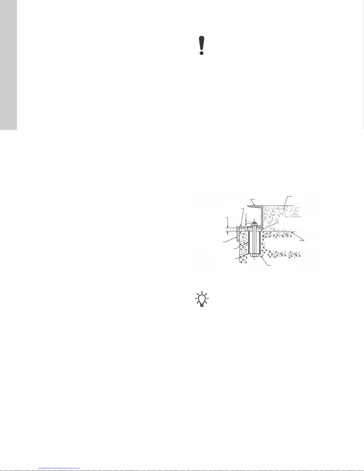
GroutBase plate
Finished grouting
0.75 - 1.25 in.
allowance
(20-32 mm)
for grout
Formwork
Pipe sleeve
Washer
Lug
Top foundation
Wedges or shims
left in place
0.25
in.
4. Installing the product
4.3 Securing the base plate
4.1 Location
• Locate the pump as close as possible to the liquid supply. Use
the shortest and most direct inlet pipe practical. Refer to
section 4.4.2 Inlet pi pe.
• Locate the pump below system level wherever possible. This
will facilitate priming, assure a steady liquid flow, and provide
a positive inlet pressure.
• The net positive suction head (NPSH) available must always
be equal to or exceed the required NPSH specified on the
pump performance curve. Make sure the required NPSH is
provided at the inlet.
• Always allow sufficient accessibility space for maintenance
and inspection. Provide a clearance of 24 in. (610 mm) with
ample head room for use of a hoist strong enough to lift the
product.
• Electrical characteristics must match those specified on the
motor nameplate, within the limits covered in section
5. Starting up the product.
• Do not expose the product to sub-zero temperatures to
prevent the pumped liquid from freezing and to prevent
damage to the e-motor. If there is frost during shutdown
periods, see sections 5. Starting up the product and 9.2 Short-
term shutdown.
4.2 Horizontal pump foundation
Install horizontal pumps permanently on a firm, raised concrete
foundation of sufficient size to dampen any vibration and prevent
any deflection or shaft misalignment. The foundation may float on
springs or be a raised part of the equipment room floor.
Proceed like this:
1. Pour the foundation without interruption to 0.75 - 1.5 in. (20-
35 mm) below the final pump level. Leave the top of the
foundation rough. Then clean and wet it down.
2. Score and groove the top surface of the foundation before the
concrete sets to provide a suitable bonding surface for the
grout.
3. Place anchor bolts in pipe sleeves for positioning allowance.
See fig. 1.
4. Allow enough bolt length for grout, lower base plate flange,
nuts, and washers.
5. Allow the foundation to cure several days before proceeding
to install the pump.
LFE pumps require grouting in order to ensure a
stable pump and motor shaft alignment.
LCSE pumps do not require alignment or grouting.
When the raised concrete foundation has been poured and
allowed to set, proceed as follows:
1. Lower the pump base plate over the anchor bolts and rest it
on loose adjustment wedges or shims placed near each
anchor bolt and at intervals not exceeding 24 in. (610 mm)
along each side.
2. Place the shims or wedges so that they raise the bottom of the
base 0.75 - 1.25 in. (20-32 mm) above the foundation,
allowing clearance for grout.
3. Level the pump shaft, flanges, and base plate using a spirit
level, adjusting the wedges or shims, as required.
4. Make sure that the pipes can be aligned to the pump flanges
without placing any strain on either flange.
5. For LFE, after pump alignment has been established, put nuts
on foundation bolts and tighten them just enough to keep the
base plate from moving.
6. Construct a formwork around the concrete foundation and
pour grout inside the base plate, as shown in fig. 1. The grout
will compensate for uneven foundation, distribute the weight
of the pump, and prevent shifting.
TM 05 4775 4713
Fig. 1 Anchor bolt installation
Use an approved, non-shrinking grout.
6
7. Allow at least 24 hours for this grout to set before proceeding
with pipe connections.
8. After the grout has thoroughly hardened, check the foundation
bolts and tighten them if necessary. Recheck the pump
alignment after tightening the foundation bolts.
Page 7
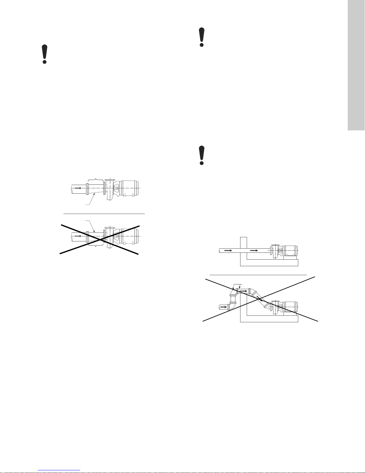
4.4 Mechanical installation
Eccentric
reducer
Concentric
reducer
Tapered side is down
Air pocket
Correct
Wrong
4.4.1 Piping
Do not let the pump support the pipes. Use pipe
hangers or other supports at proper intervals to
provide pipe support near the pump.
• Make sure that both the inlet and outlet pipes are
independently supported and properly aligned so that no strain
is transmitted to the pump when flange bolts are tightened.
• Make sure the pipes are as straight as possible, so as to avoid
unnecessary bends and fittings. Where necessary, use 45 ° or
long-sweep 90 ° pipe bends to decrease friction loss.
• Where flanged joints are used, make sure that inside
diameters match properly and that mounting holes are aligned.
• Do not apply force to pipes when making any connections!
4.4.2 Inlet pipe
The inlet pipe must be selected and installed in a manner that
minimizes pressure loss and permits sufficient liquid flow into the
pump during starting and operation.
Observe the following precautions when installing the inlet pipe:
At no point must the diameter of the inlet pipe be
smaller than that of the pump inlet port.
• If possible, run a horizontal inlet line along an even gradient.
We recommend a gradual upward slope to the pump under
suction lift conditions, and a gradual downward slope for
positive inlet pressure conditions.
• Avoid any high points, such as pipe loops (see fig. 3), as this
may create air pockets and throttle the system or cause erratic
pumping.
• Install a gate valve in the inlet line to be able to isolate the
pump during shutdown and maintenance, and to facilitate
pump removal. Where two or more pumps are connected to
the same inlet line, install two gate valves to be able to isolate
each pump from the line.
• Always install gate or butterfly valves in positions that prevent
air pockets.
Do not use globe valves, particularly when NPSH is
critical.
• During pumping operation, the valves on the inlet line must
always be fully open.
• Install properly sized pressure gauges in the tapped holes on
the pump inlet and outlet flanges.
Pressure gauges will enable the operator to monitor the pump
performance and determine whether the pump conforms to the
parameters of the performance curve. If cavitation, vapor
binding, or other unstable operating situations occur, pressure
gauges will indicate wide fluctuation in the inlet and outlet
pressures.
English (US)
Fig. 2 Inlet pipe
• Run the inlet pipe as direct as possible, and ideally, make sure
the length is at least ten times the pipe diameter. A short inlet
pipe can be the same diameter as the inlet port. A long inlet
pipe must be one or two sizes larger (depending on length)
than the inlet port, and with a reducer between the pipe and
the inlet port.
• Use an eccentric reducer, with the tapered side down. See fig.
2.
Correct
TM06 1087 1614
Air pockets
Wrong
TM06 1088 1614
Fig. 3 Air pocket prevention
7
Page 8
English (US)
4.4.3 Outlet pipe
• A short outlet pipe can be the same diameter as the pump
outlet port. A long outlet pipe must be one or two sizes larger
than the outlet port, depending on the length.
• An even gradient is best for long horizontal outlet pipes.
• Install a gate valve near the outlet port to be able to isolate the
pump during shutdown and maintenance, and to facilitate
pump removal.
• Any high points in the outlet pipe may entrap air or gas and
thus retard pump operation.
• If water hammer occurs (i.e. if check valves are used), close
the outlet gate valve before pump shutdown.
Shaft seals
The pumps are available with stuffing boxes with packing rings or
mechanical shaft seals.
Stuffing boxes
The stuffing boxes are normally packed before shipment.
If the pump is installed within 60 days after shipment, the packing
material will be in good condition for operation with a sufficient
supply of lubricating liquid.
If the pump is stored for more than 60 days, it may be necessary
to repack the stuffing boxes.
The stuffing box must be supplied at all times with a source of
clean, clear liquid to flush and lubricate the packing rings.
Packing gland adjustment
With the pump running, adjust the packing gland to permit 40 to
60 drops per minute for shaft lubrication. After initial start up,
additional packing and adjustment may be required.
Mechanical shaft seals
Mechanical shaft seals require no maintenance or adjustment.
End suction pumps equipped with mechanical shaft seals are
matched to the operating conditions for which the pump was sold.
Observe the following precautions to avoid shaft seal damage
and obtain maximum shaft seal life.
4.4.4 Coupling alignment of LCSE pumps
No alignment of the pump and motor is required.
4.4.5 Coupling alignment of LFE pumps
The pump and motor were accurately aligned from factory, but
handling during shipment could alter this pre-alignment.
1. If the pump and motor were shipped mounted on a common
base frame as an assembly, remove the coupling guard.
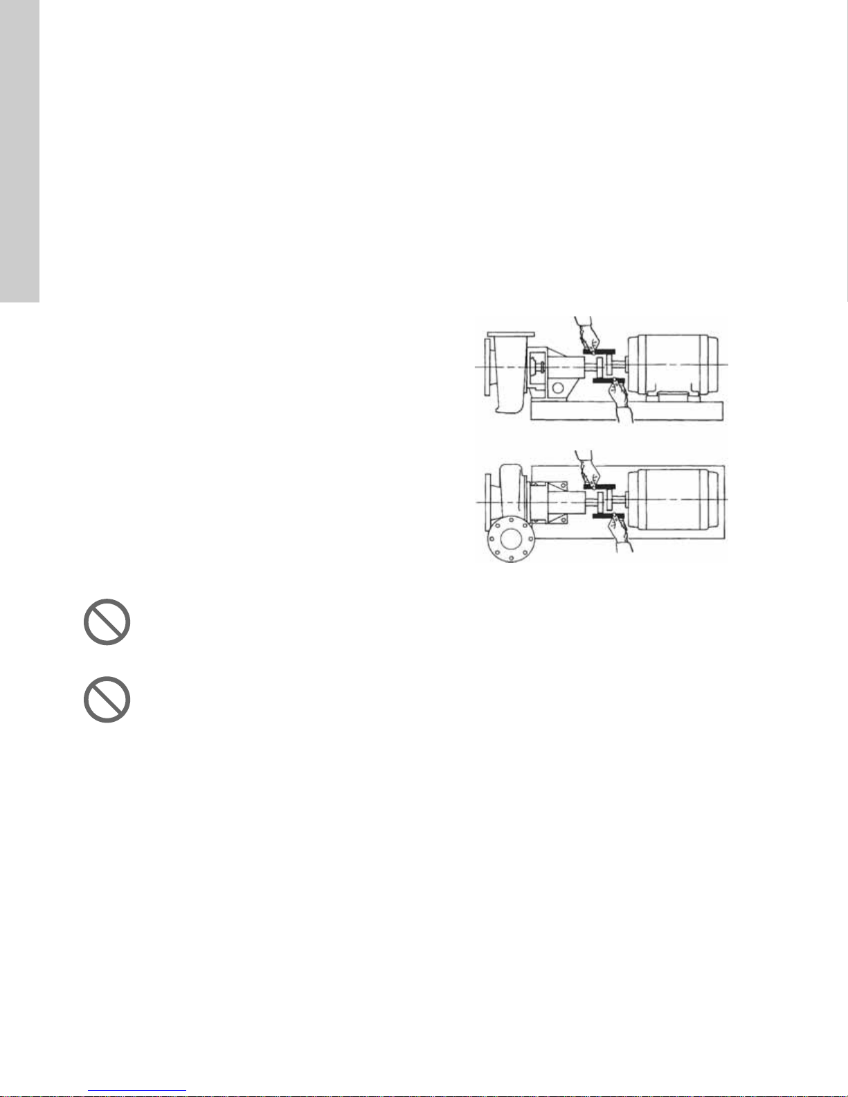
2. Checking parallel alignment
Place a straight edge across both coupling rims at the top, the
bottom, and both sides. See fig. 4. After each adjustment,
recheck all features of alignment. Parallel alignment is correct
when the measurements show that all points of the coupling
faces are within ± 0.005 in. (0.127 mm) of each other. If
misalignment is detected, loosen the motor and shift or shim
as necessary to re-align. Then re-tighten the bolts. Always
align the motor to the pump as pipe strain will occur if the
pump is shifted. Never reposition the pump on the base frame.
TM05 4794 2613
Fig. 4 Checking parallel alignment
Do not run the pump dry or against a closed valve!
Dry running will cause seal failure within minutes.
Do not exceed the temperature or pressure
limitations for the mechanical shaft seal used.
Clean and purge the inlet pipe in new installations before
installing and operating pump. Pipe scale, welding slag and other
abrasives can cause rapid shaft seal failure.
8
Page 9
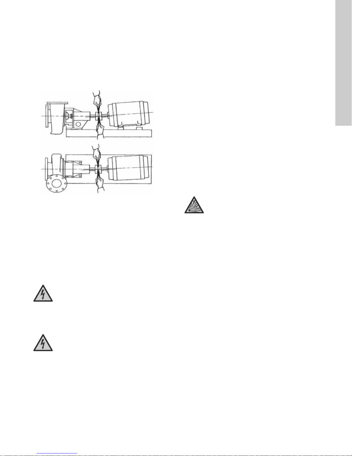
3. Checking angular alignment
Insert a pair of inside callipers or a taper gauge at four points
at 90 ° intervals around the coupling. See fig. 5. Angular
alignment is correct when the measurements show that all
points of the coupling faces are within ± 0.005 in. (0.127 mm)
of each other.
– If misalignment is detected, loosen the motor and shift or
shim as necessary to re-align. Then re-tighten the bolts.
Always align the motor to the pump as pipe strain will occur
if the pump is shifted. Never reposition the pump on the
base frame.
Fig. 5 Checking angular alignment
• Check shaft seal alignment once again after final pipe
connections to the pump have been made, motor wiring has
been checked, correct direction of rotation has been
established, and pipes have been filled with liquid.
• Leave the coupling guards off until the pump priming
procedure has been completed.
• Install the coupling guards after installation has been
completed to protect personnel from rotating machinery.
4.5 Electrical connections
DANGER
Electric shock
Death or serious personal injury
- The electrical installation must be carried out by a
qualified electrician in accordance with local
regulations and the manuals provided with the
electrical accessories.
4.6 Motors
See also section 11. PACO MLE m otors.
The motor control circuit must include the following components
in order to comply with the National Electrical Code:
Motor disconnecting device
• Install a motor disconnecting device that is capable of
disconnecting both the controller (motor starter) and the motor
from their source of power.
• Locate the disconnecting device in such a way that the
controller (motor starter) can be seen from the disconnecting
device. In all cases, the distance from the disconnecting
device to the controller must be less than 50 ft (15.24 m).
• In most installations the disconnecting device will be a circuit
breaker or fusible disconnect switch.
Motor short circuit and ground fault circuit interrupter
• A short circuit and ground fault circuit interrupter is usually a
circuit breaker or fusible disconnect switch.
• Select the circuit breaker or fuse in accordance with applicable
local and state electrical codes in addition to the National
Electrical Code.
Motor controller with current protection (magnetic starter)
• Install these components in accordance with applicable local
and state electrical codes in addition to the National Electrical
Code.
DANGER
TM05 4795 2613
4.6.1 Wiring
• Mount the control panel or the motor starter(s) close to the
pump to provide convenient control and easy installation.
• Wire panel or starter(s) to motor(s) and pilot device(s).
Wires to the motor(s) must be sized for at least 125 % of the
motor nameplate full load amps. We recommend AWG #16
Type THW stranded wire for wiring of pilot devices, such as
float switches.
• Check that the voltage, phase and frequency of the incoming
power source correspond to the voltage, phase and frequency
of the motor(s).
• Make sure that the starters are suitable for operating the pump
motors on the voltage, phase and frequency available.
Explosive environment
Death or serious personal injury
- Observe the rules and regulations generally or
specifically imposed by the relevant responsible
authorities or trade organizations in relation to
running powered equipment in an explosive
environment.
English (US)
DANGER
Electric shock
Death or serious personal injury
- Before starting any work on the product, be sure
the power supply has been switched off and that it
cannot be accidentally switched on.
9
Page 10
English (US)
5. Starting up the product
5.3 Motor direction of rotation
5.1 Priming
• End suction pumps are non-self-priming, and must be
completely primed, i.e. filled with liquid, before starting.
• If the pump will be operated with a positive inlet pressure,
prime it by opening the inlet valve and allowing liquid to enter
the pump housing. Open the air vents at this time, and make
sure all air is forced out of pump by the liquid before closing
the air vents.
• Rotate the shaft by hand to free entrapped air from the
impeller passageways.
• If the pump will be operating with a suction lift, priming must
be accomplished by other methods. Use foot valves or
ejectors, or fill the pump housing and the inlet line manually
with liquid.
Never run the pump dry in the hope that it will prime
itself. The result will be serious damage to the shaft
seals, pump wear rings and shaft sleeves.
5.2 Pre-start checklist
WARNING
Product failure
Death or serious personal injury
- Do not operate the product above the nameplate
conditions.
Make the following inspections before starting your end suction
pump:
1. Make sure the inlet and outlet pipes have been cleaned and
flushed to remove dirt and debris.
2. Double check the direction of rotation is clockwise. Operating
in reverse will destroy the impeller and shaft.
3. Make sure all wiring connections to the motor and starting
device are in accordance with the wiring diagram.
4. If the motor has been in storage for a long time, either before
or after installation, refer to the motor instructions before
starting.
5. Check the voltage, phases, and frequency with the motor
nameplate. Turn the impeller by hand to make sure it rotates
freely.
6. Tighten the plugs in the gauge and drain holes. If the pump is
fitted with pressure gauges, keep the gauge cocks closed
when they are not in use.
7. Check the inlet and outlet pipes for leaks, and make sure all
flange bolts are securely tightened.
Never check the motor direction of rotation unless
the pump and motor couplings have been
disconnected and physically separated. Failure to
follow this instruction can result in serious damage
to the pump and the motor if the direction of rotation
is wrong.
5.4 Starting the pump
DANGER
Moving machine parts
Death or serious personal injury
- Mount an approved coupling guard before
operating the product.
1. Install the factory-provided coupling guard on coupled
products.
2. Fully open the gate valve (if any) in the inlet line, and close
the gate valve in the outlet line.
3. Fill the inlet line with liquid and completely prime the pump.
4. Start the pump.
5. Immediately make a visual check of the pump and inlet pipe
for pressure leaks.
6. Immediately after the pump has reached full operating speed,
slowly open the outlet gate valve until complete system flow is
achieved.
7. Check the outlet pipe for pressure leaks.
8. If the pump is fitted with pressure gauges, open gauge cocks
and record pressure readings for future reference. Verify that
the pump is performing in accordance with the parameters
specified in the performance curves.
9. Check and record voltage, amperage per phase, and
kilowatts, if a wattmeter is available.
5.5 Voltage a nd frequency variation
The motor will operate satisfactorily under the following voltage
and frequency variations, but not necessarily in accordance with
the standards established for operation under rated conditions:
• The voltage variation may not exceed 10 % above or below
the rating specified on the motor nameplate.
• The frequency variation may not exceed 5 % above or below
the motor rating.
• The sum of the voltage and frequency variations may not
exceed 10 % above or below the motor rating, provided the
frequency variation does not exceed 5 %.
6. Storing and handling the product
See sections 3.3 T emporary storage af ter delivery, 9.2 Short-term
shutdown and 9.3 Long-term shutdown.
10
Page 11

7. Product introduction
CAT#: 21-20709-133L01-25E1MS1
STOCK#: 91893522
SER#: 1971001000
GPM: 234
TDH: 88
MFD BY GRUNDFOS CBS INC 34014412
IMP
DIA
5.11
:
This data booklet describes:
• LFE end-suction, frame-mounted pumps with integrated VFD
• LCSE end-suction, close-coupled, split-coupling pumps with
integrated VFD.
7.1 Applications
We recommend the integrated VFD end suction pumps for these
applications:
• commercial and industrial cooling systems
– pumping both primary and secondary cooling water
• condenser water systems
• district cooling systems
• water distribution systems
• irrigation systems.
7.2 Pumped liquids
Clean, thin, non-aggressive liquids, not containing solid particles
or fibers. Do not pump liquids that will attack the pump materials
chemically.
7.3 Pump identification
Pumps are identified by catalog and serial numbers (LFE
nameplate shown in fig. 6). These numbers are stamped on the
pump nameplate as shown in fig. 6, affixed to each pump volute
casing, and should be referred to in all correspondence with
Grundfos.
Fig. 6 Nameplate
8. Servicing the product
8.1 Maintaining the product
WARNING
Moving machine parts
Death or serious personal injury
- Before any inspection, maintenance, service or
repair of the product, make sure the motor controls
are in the "OFF" position, locked and tagged.
8.2 Lubricating the product
8.2.1 Lubricating the motor
Always follow the motor manufacturer's lubricating instructions, if
they are available, and periodically check grease fittings and
drain plugs for leaks. Use the standard lubrication interval. See
the installation and operating instructions or the lubrication plate
on the E-motor. If the lubricating instructions are not available,
refer to the table below for recommended lubricating intervals.
Recommended lubricating intervals
Motor rpm Motor hp Operating conditions
Standard Severe Extreme
1750
and below
above 1750 all hp 6 mo 3 mo 3 mo
Standard conditi ons:
Operating 8 hours per day operation, normal or light load, clean
air, 100 °F (37 °C), maximum ambient temperature.
Severe conditions:
Operating continuously 24 hours, shock loads or vibrations,
poor ventilation, 100-150 °F (37-65 °C), ambient temperature.
Extreme conditions:
Continuous operation, heavy shocks or vibrations, dirt or dust in
the air, extremely high ambient temperature.
TM 06 1036 1414
3.00-7.50 3 yrs 1 yr 6 mo
10-30 1-3 yrs 6 mo-1 yr 3 mo
English (US)
11
Page 12

English (US)
8.2.2 Lubricating the pump
Grease lubrication
In the standard configuration, LFE pumps with horizontal bearing
frames have sealed-for-life bearings (requiring no lubrication).
For customized pumps with regreasable bearings, use an
approved grease and proceed as described below.
Approved grease lubricants
Manufacturer Lubricant
Shell Dolium
Exxon Polyrex
Chevron
SRI GreaseNLGI 2
Black Pearl - NLGI 2
p
R
p
Philips Polytacറ
Texaco Polystar RB
• Remove the drain plug, if any, and the filler plug. Add clean
lubricant until grease appears at the drain hole or along the
pump shaft. On pumps with drain hole, all old grease can be
purged. In such cases, the drain hole must be left unplugged
for several minutes during pump operation to allow excess
grease to be forced out.
• Lubricate the pump bearings at 1-3 month intervals,
depending on the severity of the environment. Pumps in a
clean, dry, moderate temperature (100 °F (37 °C) maximum)
environment must be regreased at 3-month intervals.
Do not over-grease! Too much grease can cause
overheating and premature bearing failure.
Oil lubrication
LFE pumps with oil lubricated bearings are fitted with a
transparent reservoir, a constant-level oiler, that maintains the oil
level about the centerline of the bearing. See fig. 7.
• Follow a regular maintenance program. When necessary,
renew the oil supply in the reservoir of the constant-level oiler.
• Change the oil after the first 200 hours of operation. To change
the oil, remove the drain plug at the bottom of the bearing
cover and the filler plug, that also acts as a vent plug, at the
top of the bearing frame. After draining the oil, replace the
fittings and refill the reservoir with an acceptable oil from the
table List of acceptable oil lubricants on page 12. After the first
oil change, the oil must be changed again at 2000 hours and
then at intervals of 8000 hours or once a year, thereafter.
Oil level
Fig. 7 Oil lubrication
List of acceptable oil lubricants
Lubricant manufacturer Bearing oil brand name
Aral Refining Co.
British Petroleum Co.
Calypsol Oil Co.
Aral Oil CMU
Aral Oil TU 518
BP Energol
TH 100-HB
Calypsol Bison Oil
SR 25 or SR 36
Chevron
Standard Oil Co.
Hydraulic Oil 11
Circulating oil 45
Esso-Mar 25
Esso Corp
Teresso 47
Esstic 50
Fina Oil Co.
Gulf Refining Co.
Socony Mobil Oil Co.
Fina hydran 34
Fina Cirkan 32
Gulf Harmony 47
Gulf Paramount 45
Vac hlp 25
Mobulix D.T.E. 25
Shell Oil Co. Shell Tellus oil 29
Sundco Oil Co. Sunvis 821
The Texas Co.
Texaco ursa oil P 20
Dea viscobil sera 4
TM06 1089 1614
12
Page 13
8.3 Disassembling the pump
8.3.1 Preparations before disassembling the pump
DANGER
Electric shock
Death or serious personal injury
- Before starting any work on the product, be sure
the power supply has been switched off and that it
cannot be accidentally switched on.
CAUTION
Toxic material
Minor or moderate personal injury.
- Wash down the pump before doing any work on it.
DANGER
Hot, caustic, flammable or toxic materials,
including vapors
Death or serious personal injury
- Be extremely cautious when venting and/or
draining hazardous liquids.
- Wear protective clothing when there are caustic,
corrosive, volatile, flammable, or hot liquids.
- DO NOT breathe toxic vapors.
- DO NOT allow sparks, open fire, or hot surfaces
near the equipment.
Complete disassembly instructions are outlined below. Proceed
only as far as required to perform the maintenance work needed.
1. Switch off the power supply.
2. Drain the system.
3. Flush the system, if necessary.
4. For closed coupled units: Remove the motor fixation bolts.
8.3.2 Disassembling the liquid end
1. Remove the pump housing screws (8B).
2. Remove the back pull-out bearing frame (20Y) from the pump
housing (1A).
3. Remove the impeller screw (8A).If necessary, use a strap
wrench around the impeller or shaft to prevent rotation.
8.3.3 Disassembling the bearing frame (LFE)
1. Remove the slinger (13G).
2. Remove the lip seal(s) (14S), if any.
3. Remove the bearing housing locking ring (61K).
4. Press or tap on the pump end of the bearing-shaft assembly
until one bearing is out.
5. When one bearing is out, remove the second locking ring
(61F), then remove the complete bearing-shaft assembly from
the bearing housing.
6. Remove the shaft locking ring (61C) and press off the
bearings.
7. Press new bearings onto the shaft; remember to press only on
the inner race of the bearings while pressing them on.
8. Assemble the bearing frame in the reverse procedure used for
disassembling.
9. Observe the following when reassembling the bearing frame.
– Replace the lip seals (14S) if they are worn or damaged.
– Replace the bearings (18A) and (18B) if they are loose,
rough or noisy when rotated.
– Check the shaft (6A) for shaft runout at the sleeve (5A) area.
Maximum permissible runout is 0.002 in. (0.0508 mm) total
indicator runout.
English (US)
WARNING
Moving machine parts
Death or serious personal injury
- Do not insert a screwdriver between the impeller
vanes to prevent rotation.
4. Use an appropriately sized puller aligned behind the impeller
vanes to remove the impeller (3A) from the shaft (6A).
5. Remove the impeller key (12A).
6. Remove the back plate screws (8D). Remove the back plate
(2K) and the seal housing (26P).
7. Place the seal housing on a flat surface and press out the
shaft seal (14A).
8. If the shaft sleeve (5A) requires replacement, heat it evenly to
approximately 350 °F (176 °C) to loosen the thread-locking
fluid. Twist the sleeve off the shaft (6A).
13
Page 14
English (US)
8.4 Replacing the shaft seal (LCSE pumps)
1. Complete preparations listed in section 8.3 Disassembling the
pump.
2. Remove the coupling guard screws (8E).
3. Remove the coupling guard (34F).
4. Remove the nut (35E) and the bolt (8E) that hold the coupling
halves together.
5. Pry apart the coupling halves (23D), remove the coupling key
(12B).
Mark or measure the original position of the pump
coupling on the motor side.
6. For pumps with lubrication lines, unscrew the tubing
connector from the pipe tee of the air vent assembly. Thread
sealing compound was applied to the threads during factory
assembly, and the resulting bond may retard but will not
prevent manual disassembling.
7. Remove the seal housing cap screws and slide the seal
housing (2N) up the shaft to remove it.
8. Remove the shaft seal (14A) manually from the shaft (6A).
Apply water-soluble lubricant to the shaft, if necessary, to
ease the removal of the shaft seal. Pull the seal head
assembly manually from the shaft, using a slight twisting
motion (as necessary) to loosen bellows from shaft.
9. Remove and discard the shaft seal spring and the shaft seal
retainer.
10. Remove and discard the shaft seal seat from the seal housing
(2N) and thoroughly clean the inside cavity of the seal
housing.
11. The interior surface of the bellows on a new shaft seal is
coated with a bonding agent that adheres to the motor shaft.
When the old shaft seal is removed, the bonding agent no
longer exists and the bellows may crack or split during
removal. We always recommend that you install a new
mechanical shaft seal if it becomes necessary to remove the
existing shaft seal from the shaft.
12. Clean and lubricate the shaft (6A) with a water-soluble
lubricant and make sure no sharp edges can cut or scratch
the bellows of the new shaft seal.
13. Press the new shaft seal seat firmly into the seal housing.
Avoid direct contact between the seal face and metallic or
abrasive objects, and wipe the seal face clean after
installation to ensure an abrasive-free sealing surface.
14. Slide the new shaft seal (14A) onto the shaft by applying even
pressure to the shaft seal.
15. Install the shaft seal housing (2N) on the shaft.
16. See the reassembly instructions in section 8.6 Reassembling
the pump.
8.5 Replacing the wear ring
1. Complete preparations in sections 8.3.1 Preparations before
disassembling the pump and 8.3.2 Disassembling the liquid
end.
2. Remove the rotating assembly.
3. Remove the pump housing (1A) from the pipes, if necessary,
to facilitate easy access to the interior of the pump housing. If
necessary, remove the flange bolts at the pipes.
4. Remove a worn wear ring (4A) by drilling two holes slightly
smaller than the width of the wear ring into the exposed edge
of the wear ring. Insert a chisel into the holes to completely
sever the wear ring at the holes and break the wear ring into
two halves for easy removal.
5. Clean the wear ring cavity in the pump housing prior to
installing a new wear ring to ensure a properly aligned fit.
6. To reassemble, press fit the new wear ring squarely into the
pump housing cavity. Tap the wear ring into place to make
sure it is pressed home into the cavity.
Do not use metal tools on the wear ring surfaces.
Use only rubber, rawhide, wood or other soft
material to prevent damage to the wear ring.
8.6 Reassembling the pump
WARNING
Moving machine parts
Death or serious personal injury
- Reinstall approved coupling guards and make sure
they are in place prior to operation.
1. Clean all parts before reassembly.
2. Refer to the parts list to identify required replacement items.
3. Specify the pump serial or catalog number when ordering
parts.
4. Reassemble the pump in the reverse procedure used for
disassembling.
5. Observe the following when reassembling the pump:
– All mechanical seal components must be in good condition
or leakage may result. We recommend that you replace the
complete shaft seal.
– Install new shaft sleeves by bonding them to the shaft with a
thread-locking fluid.
6. Re-install the coupling guards on coupled pumps.
14
Page 15
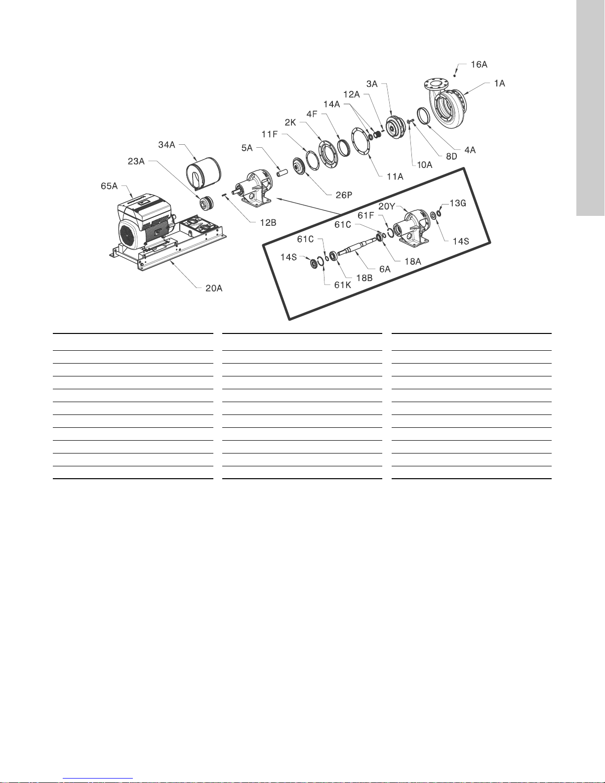
8.7 LFE, exploded view and parts list
English (US)
TM06 6570 1816
Pos. Description Pos. Description Pos. Description
1A Pump housing 11F Gasket 20A Base plate
2K Backplate 12A Key 20Y Bearing frame
3A Impeller 12B Key 23A Coupling hub
4A Wear ring 13G Slinger 26P Seal housing
4F* Balance wear ring 14A Shaft seal 34A Coupling guard
5A Shaft sleeve 14S Lip seal 61C Locking ring
6A Shaft 16A Drain plug 61F Locking ring
8D Cap screw 18A Bearing, inboard 61K Locking ring
10A Washer 18B Bearing, outboard 65A Motor
11A Ga ske t
* If applicable
15
Page 16
English (US)
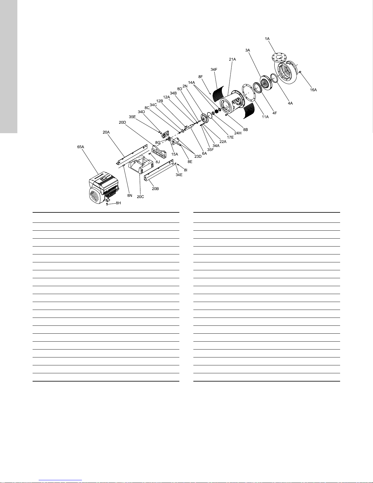
8.8 LCSE, exploded view and parts list
Pos. Description Pos. Description
1A Pump housing 15A Locating ring
2N Shaft seal housing 16A Drain plug
3A Impeller 17E O-ring
4A Wear ring 20A+20B Base plate rails
4F Balance wear ring 20C Base plate
6A Pump shaft 20D Pump support
8B Cap screw 21A Motor stool
8C Screw 22A Stud
8D Screw 23D Coupling halves
8E Bolt 24H Bushing
8F Screw 34A Washer
8G Screw 34B Washer
8H Cap screw 34C Washer
8I Cap screw 34D Washer
8J Screw 34E Washer
8N Screw 34F Coupling guard
11A Ga ske t 35 E Nu t
12A Key 35F Nut
12B Key 65A Motor
14A Shaft seal
TM06 4401 2215
16
Page 17

9. Taking the product out of operation
The following shutdown procedures will apply for the L pumps in
most normal shutdown situations. If the pump will be inoperative
for a long time, follow the storage procedures in section 9.3 Long-
term shutdown.
9.1 General procedure
• Always close the outlet gate valve before stopping the pump.
Close the valve slowly to prevent hydraulic shock.
• Disconnect and lock off the power to the motor.
9.2 Short-term shutdown
• For overnight or temporary shutdown periods under nonfreezing conditions, the pump may remain filled with liquid.
Make sure the pump is fully primed before restarting.
• For short or frequent shutdown periods under freezing
conditions, keep the liquid moving within the pump housing
and insulate or heat the pump exterior to prevent freezing.
9.3 Long-term shutdown
• For long shutdown periods, or to isolate the pump for
maintenance, close the inlet gate valve. If no inlet valve is
used and the pump has positive inlet pressure, drain all liquid
from the inlet line to stop the liquid flow into the pump inlet.
Remove the plugs in the pump drain and vent holes, as
required, and drain all liquid from the pump housing.
• If there will be freezing conditions during long shutdown
periods, completely drain the pump and blow out all liquid
passages and pockets with compressed air. Freezing of the
pumped liquid can also be prevented by filling the pump with
antifreeze solution.
English (US)
17
Page 18
English (US)
10. Fault finding
DANGER
Electric shock
Death or serious personal injury
- Before starting any work on the product, be sure
the power supply has been switched off and that it
cannot be accidentally switched on.
CAUTION
Toxic material
Minor or moderate personal injury.
- Wash down the pump before doing any work on it.
Fault Cause Remedy
1. Outlet pressure is too low. a) The speed of rotation is too low. Reestablish correct speed and direction of
b) The system pressure is lower than
anticipated.
c) There is air or gas in the pumped liquid. Remove the air from the pumped liquid.
d) The wear rings are worn. Replace the wear rings.
e) The impeller is damaged. Repair or replace the impeller.
f) The impeller diameter is too small. Replace the impeller with one of the correct
g) Wrong direction of rotation. Interchange two wires in the power supply.
h) The pump has lost its prime. Re-prime the pump.
i) There is insufficient NPSH. Restore required NPSH.
j) Passages are restricted. Clean the impeller and pump housing
k) Joints or the stuffing box are leaking. • Tighten the joints or the stuffing box gland.
2. Insufficient inlet pressure. a) The inlet line is drawing air. Tighten the connections.
b) The suction lift is too high or there is
insufficient NPSH.
c) Air or gas is trapped in the pumped liquid. Remove the trapped air/gas from liquid.
d) The strainer is clogged. Clean the strainer.
3. Noise level has increased. a) Poor alignment of the pump.
Inlet and outlet pipe clamps are loose.
b) Cracked foundation. Repair the foundation.
c) Worn ball bearings. • Replace the worn bearings.
d) The motor is unbalanced. • Disconnect the motor and operate it alone.
e) Hydraulic resonance. • Alter the resonant pipes.
DANGER
Hot, caustic, flammable or toxic materials,
including vapors
Death or serious personal injury
- Be extremely cautious when venting and/or
draining hazardous liquids.
- Wear protective clothing when there are caustic,
corrosive, volatile, flammable, or hot liquids.
- DO NOT breathe toxic vapors.
- DO NOT allow sparks, open fire, or hot surfaces
near the equipment.
rotation.
Check the system curve.
diameter.
passages.
• Replace the shaft sleeve.
• Replace the gaskets.
Reduce the suction lift or restore required
NPSH.
• Ensure proper alignment of the pump and
the motor.
• Support the inlet and outlet pipes.
• Make sure the vibration dampers, flexible
pipes, and conduit connectors are installed
correctly.
• Renew the lubrication.
• Remove large pieces of debris, such as
wood or rags from the pump.
• Clean out the pump, if necessary.
• Change the pump speed.
• Insert a pulsation damper on the pump or the
pipes.
• Insert a flow straightener.
18
Page 19

Fault Cause Remedy
4. Insufficient flow. a) The pump is not primed. Prime the pump.
b) The system pressure exceeds the shut off
pressure.
c) The rotation speed is too low. Reestablish the correct speed of rotation.
d) The suction lift is too high or there is
insufficient NPSH.
e) The strainer or impeller is clogged. Clean the strainer and impeller passages.
f) Wrong direction of rotation. Reestablish the correct direction of rotation.
g) Leaking joints. Tighten the joints.
h) Broken shafting or coupling. Repair or replace damaged parts.
i) Closed inlet valve. If the inlet valve is closed, open it slowly.
j) There is not enough inlet pressure for hot
or volatile liquids.
k) Foot valve is too small. Replace the foot valve.
l) Worn or damaged hydraulic parts. Repair or replace the worn parts.
m) Excessive clearance between the wear
surfaces.
5. Pump loses its prime after
starting.
6. Excessive power required. a) The speed of rotation is too high. Reduce the speed of rotation.
a) Joints or the stuffing box are leaking. • Tighten the joints or the stuffing box gland.
b) The suction lift is too high or there is
insufficient NPSH.
b) The pump is operating beyond its
recommended performance range.
c) The specific gravity or the viscosity of the
pumped liquid is too high.
d) The shaft is bent. Replace the shaft.
e) Stuffing-boxes too tight. Retighten the stuffing box if possible.
f) Impeller clearances are too small causing
rubbing or worn wear surfaces.
g) There is an electrical or mechanical defect
in the motor.
h) The pump is restricted in its rotation. Remove any obstacles or replace any worn
i) Incorrect lubrication of the motor. Reestablish correct lubrication of the motor.
• Increase the liquid level on the inlet side.
• Open the isolating valve in the inlet pipe.
Reduce the suction lift or restore required
NPSH.
Reestablish required inlet pressure.
See section 8.5 Replacing the wear ring.
• Replace the shaft sleeve.
• Replace the gaskets.
Reduce the suction lift or restore required
NPSH.
Set the duty point in accordance with the
recommended performance range.
If less flow is sufficient, reduce the flow on the
outlet side, or fit the pump with a more powerful
motor.
Alternatively, repair or replace the stuffing box.
Adjust the impeller clearance, if possible, or
replace the wear ring.
Contact your local service center for
diagnostics.
parts.
English (US)
19
Page 20
English (US)
11. PACO MLE motors
Grundfos E-pumps have standard motors with integrated variable
frequency drive. The pumps are for a single-phase or three-phase
power supply connection.
12. Installing the motor
The pump must be secured to a firm, raised concrete foundation
by means of bolts through the holes in the flange or baseplate.
11.1 Pumps without factory-fitted sensor
The pumps have a built-in PI controller and can be set up for an
external sensor enabling control of the following parameters:
• pressure
• differential pressure
• temperature
• differential temperature
•flow rate
• liquid level in a tank.
From the factory, the pumps have been set to control mode
uncontrolled. The PI controller can be activated by means of the
Grundfos GO Remote or R100.
11.2 Pumps with pressure sensor
The pumps have a built-in PI controller and are set up with a
pressure sensor enabling control of the pump outlet pressure.
The pumps are set to control mode controlled. The pumps are
typically used to hold a constant pressure in variable-demand
systems or differential pressure in closed-loop applications.
11.3 Settings
The description of settings apply both to pumps without factoryfitted sensor and to pumps with a factory-fitted pressure sensor.
Setpoint
The desired setpoint can be set in three different ways:
• directly on the pump control panel
• via an input for external setpoint signal
• by means of the Grundfos GO remote or wireless remote
control.
Other settings
All other settings can only be made by means of the Grundfos GO
Remote or R100.
Important parameters such as actual value of control parameter,
power consumption, etc. can be read via the Grundfos GO
remote or R100.
If special or customized settings are required, use Grundfos PC
Tool E-products. Contact Grundfos for more information.
In order to retain the UL/cUL approval, follow the
additional installation procedures on page 54.
12.1 Motor cooling
To ensure sufficient cooling of motor and electronics, observe the
following requirements:
• Make sure that sufficient cooling air is available.
• Keep the temperature of the cooling air below 104 °F (40 °C).
• Keep cooling fins and fan blades clean.
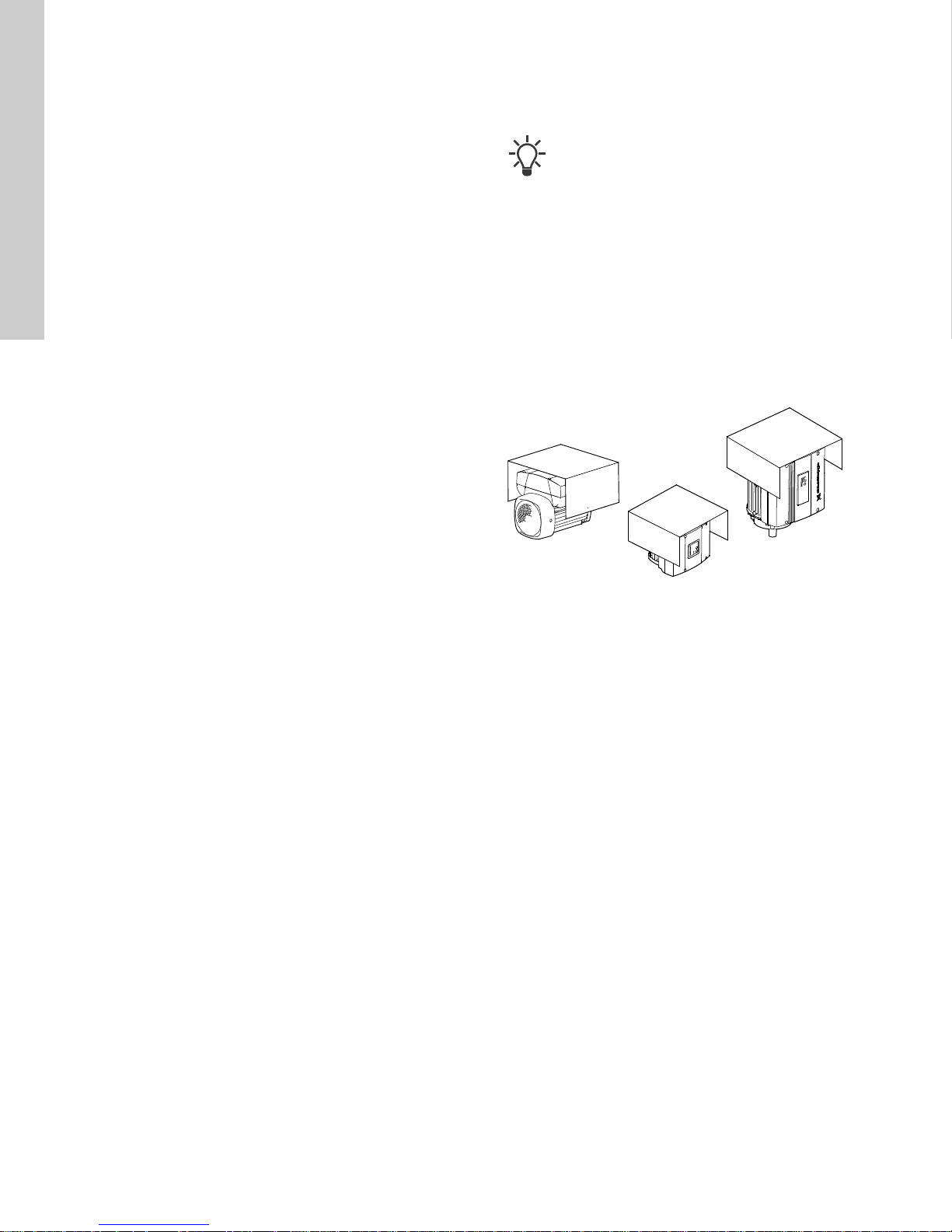
12.2 Outdoor installation
When installed outdoors, the pump must be provided with a
suitable cover to avoid condensation on the electronic
components. See fig. 8.
TM00 8622 0101 - TM02 8514 0304
Fig. 8 Examples of covers
Remove the drain plug pointing downwards in order to avoid
moisture and water build-up inside the motor.
Vertically mounted pumps are IP55 after removal of the drain
plug. Horizontally mounted pumps change enclosure class to
IP54.
20
Page 21

13. Electrical connection
L1
L2
L3
L2
L1
L3
PE
For description of how to connect E-pumps electrically, see the
following sections:
13.1 Three-phase pumps, 3-10 hp.
13.2 Three-phase pumps, 15-30 hp.
13.1 Three-phase pumps, 3-10 hp
DANGER
Electric shock
Death or serious personal injury
- The user or the installer is responsible for the
installation of correct grounding and protection
according to current national and local standards.
- All operations must be carried out by qualified
personnel.
DANGER
Electric shock
Death or serious personal injury
- Disconnect all electric supply circuits and ensure
these have been switched off for at least 5 minutes
before making any connections in the pump
terminal box. For instance, the signal relay may be
connected to an external supply which is still
connected when the power supply is
disconnected.
The above warning is indicated on the motor
terminal box by this yellow label:
13.1.1 Preparation
Before connecting the E-pump to the power supply, take the
issues illustrated in the figure below into consideration.
ELCB
Fig. 9 Power supply-connected pump with power switch,
backup fuses, additional protection and protective
grounding
13.1.2 Protection against electric shock - indirect contact
DANGER
Electric shock
Death or serious personal injury
- Ensure the pump is grounded in accordance with
national regulations. As the leakage current of 510 hp (4-7.5 kW) motors is > 3.5 mA, take extra
precautions when grounding these motors.
EN 50178 and BS 7671 specify the following precautions when
leakage current > 3.5 mA:
• Install the pump in a stationary, permanent position.
• Connect the pump permanently to the power supply.
• Carry out the grounding connection as duplicate leads.
Mark the protective ground leads with a yellow/green (PE) or
yellow/green/blue (PEN) color marking.
13.1.3 Backup fuses
For recommended fuse sizes, see section 28.1.1 Supply voltage.
13.1.4 Additional protection
If the pump is connected to an electric installation where an
ground leakage circuit breaker (ELCB) is used as additional
protection, use a circuit breaker of a type marked with the
following symbols:
ELCB
This circuit breaker is type B.
Take into account the total leakage current of all the electrical
equipment in the installation.
Check the leakage current of the motor in normal operation; see
section 28.1.3 Leakage current.
During start and at asymmetrical supply systems, the leakage
current can be higher than normal and may cause the ELCB to
trip.
13.1.5 Motor protection
The pump requires no external motor protection. The motor
incorporates thermal protection against slow overloading and
blocking (IEC 34-11, TP 211).
13.1.6 Protection against voltage transients
TM00 9270 4696
The pump is protected against voltage transients by built-in
varistors between the phases and between phases and ground.
English (US)
21
Page 22

English (US)
L1
L2
L3
L1
L2
L3
13.1.7 Supply voltage and power supply
3 x 440-480 V - 10 %/+ 10 %, 60 Hz, PE.
3 x 208-230 V - 10 %/+ 10 %, 60 Hz, PE.
The supply voltage and frequency are marked on the pump
nameplate. Make sure that the pump is suitable for the power
supply of the installation site.
The wires in the terminal box must be as short as possible.
Excepted from this is the protective ground lead which must be
long enough that it is the last one to be disconnected in case the
cable is inadvertently pulled out of the cable entry.
Fig. 10 Power connection
Cable glands
Cable glands comply with EN 50626.
• 2 x M16 cable gland
• 1 x M20 cable gland
• 2 x M16 knock-out cable entries.
DANGER
Electric shock, malfunction or damage
Death or serious personal injury; product damage or
failure
- Replace power supply cable immediately if
damaged. Only qualified personnel must replace
it.
Grid types
Three-phase E-pumps can be connected to all grid types.
DANGER
Electric shock
Death or serious personal injury; product damage or
failure
- Do not connect three-phase E-pumps to a power
supply with a voltage between phase and ground
of more than 440 V.
13.1.8 Start/stop of pump
The number of starts and stops via the power supply
must not exceed 4 times per hour.
When the pump is switched on via the power supply, it will start
after approximately 5 seconds.
If a higher number of starts and stops is desired, use the input for
external start/stop when starting/stopping the pump.
When the pump is switched on via an external On/Off switch, it
will start immediately.
Automatic restart
If a pump set up for automatic restart is stopped due
to a fault, it will restart automatically when the fault
has disappeared.
However, automatic restart only applies to fault types set up to
automatic restart. These faults could typically be one of these
faults:
• temporary overload
• fault in the power supply.
13.1.9 Connections
If no external On/Off switch is connected, connect
terminals 2 and 3 using a short wire.
TM03 8600 2007
As a precaution, the wires to be connected to the following
connection groups must be separated from each other by
reinforced insulation in their entire lengths:
Group 1: Inputs
• start/stop terminals 2 and 3
• digital input terminals 1 and 9
• setpoint input terminals 4, 5 and 6
• sensor input terminals 7 and 8
• GENIbus terminals B, Y and A
All inputs (group 1) are internally separated from the power-
conducting parts by reinforced insulation and galvanically
separated from other circuits.
All control terminals are supplied with protective extra-low voltage
(PELV), thus ensuring protection against electric shock.
Group 2: Output (relay signal, terminals NC, C, NO)
The output (group 2) is galvanically separated from other circuits.
Therefore, the supply voltage or protective extra-low voltage can
be connected to the output as desired.
22
Page 23
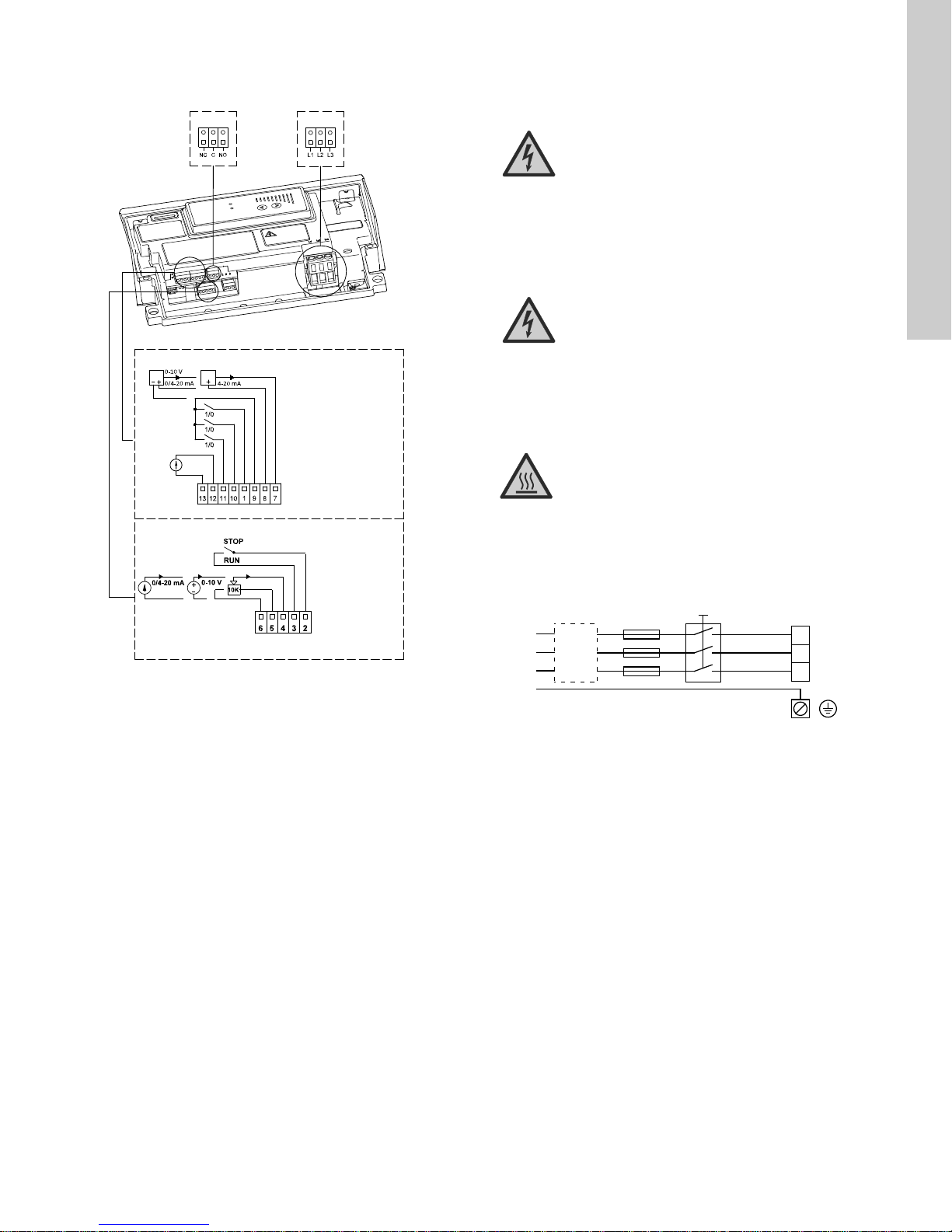
13.1.10 Three-phase pumps, 3-10 hp
L1
L2
L3
L2
L1
L3
PE
Group 3: Power supply (terminals L1, L2, L3)
Group 2
13: GND (frame)
12: Analog output
11: Digital input 4
10: Digital input 3
1: Digital input 2
9: GND (frame)
8: +24 V
7: Sensor input
B: RS-485B
Y: Screen
A: RS-485A
6: GND (frame)
5: +10 V
4: Setpoint input
3: GND (frame)
2: Start/stop
13.2 Three-phase pumps, 15-30 hp
DANGER
Group 3
Electric shock
Death or serious personal injury
- The user or the installer is responsible for the
installation of correct grounding and protection
according to current national and local standards.
- All operations must be carried out by qualified
personnel.
English (US)
DANGER
Electric shock
Death or serious personal injury
- Disconnect all electric supply circuits and ensure
these have been switched off for at least 5 minutes
before making any connections in the pump
terminal box. For instance, the signal relay may be
connected to an external supply which is still
connected when the power supply is
disconnected.
CAUTION
Hot surface
Group 1
13.2.1 Preparation
Before connecting the E-pump to the power supply, take the
issues illustrated in the figure below into consideration.
Minor or moderate personal injury
- Wear hand protection and use care when handling
terminal box when product is operating. The
surface of the terminal box may be above 158 °F
(70 °C) when the pump is operating.
Fig. 11 Connection terminals
A galvanic separation must fulfill the requirements for reinforced
insulation including creepage distances and clearances specified
in EN 60335.
TM05 2985 0812
ELCB
TM00 9270 4696
Fig. 12 Power supply-connected pump with power switch,
backup fuses, additional protection and protective
grounding
23
Page 24
English (US)
13.2.2 Protection against electric shock - indirect contact
DANGER
Electric shock
Death or serious personal injury
- Ensure the pump is grounded in accordance with
national regulations. As the leakage current of 510 hp (4-7.5 kW) motors is > 3.5 mA, take extra
precautions when grounding these motors.
EN 61800-5-1 specifies that the pump must be stationary and
installed permanently when the leakage current is > 10 mA.
One of the following requirements must be fulfilled:
• A single protective ground lead (7 AWG minimum copper)
Fig. 13 Connection of a single protective ground lead using
one of the leads of a 4-core power cable (7 AWG
minimum)
• Two protective ground leads of the same cross-sectional area
as the power supply leads, with one lead connected to an
additional ground terminal in the terminal box.
13.2.3 Backup fuses
For recommended fuse sizes, see section 28.2.1 Supply voltage.
13.2.4 Additional protection
If the pump is connected to an electric installation where an
ground leakage circuit breaker (ELCB) is used as additional
protection, use a circuit breaker of a type marked with the
following symbols:
ELCB
This circuit breaker is type B.
Take into account the total leakage current of all the electrical
equipment in the installation.
Check the leakage current of the motor in normal operation. See
section 28.2.3 Leakage current.
During start and at asymmetrical supply systems, the leakage
current can be higher than normal and may cause the ELCB to
trip.
13.2.5 Motor protection
The pump requires no external motor protection. The motor
incorporates thermal protection against slow overloading and
blocking (IEC 34-11, TP 211).
13.2.6 Protection against voltage transients
The pump is protected against voltage transients in accordance
with EN 61800-3 and is capable of withstanding a VDE 0160
pulse.
TM04 3021 3508TM03 8606 2007
The pump has a replaceable varistor which is part of the transient
protection.
Over time this varistor will become worn and will need to be
replaced. When the time comes for replacement, Grundfos GO,
R100 and PC Tool E-products will indicate this as a warning. See
section 27. Maintaining and servicing the motor.
Fig. 14 Connection of two protective ground leads using two of
the leads of a 5-core power supply cable
Protective ground leads must always have a yellow/green (PE) or
yellow/green/blue (PEN) color marking.
24
Page 25

13.2.7 Supply voltage
3 x 440-480 V - 10 %/+ 10 %, 60 Hz, PE.
The supply voltage and frequency are marked on the pump
nameplate. Make sure that the motor is suitable for the power
supply of the installation site.
The wires in the terminal box must be as short as possible.
Excepted from this is the protective ground lead which must be so
long that it is the last one to be disconnected in case the cable is
inadvertently pulled out of the cable entry.
Torques, terminals L1-L3:
Min. torque: 1.6 ft-lbs (2.2 Nm)
Max. torque: 1.8 ft-lbs (2.4 Nm)
Fig. 15 Power connection
Cable glands
Cable glands comply with EN 50626.
• 1 x M40 cable gland
• 1 x M20 cable gland
• 2 x M16 cable gland
• 2 x M16 knock-out cable entries.
DANGER
Electric shock, malfunction or damage
Death or serious personal injury; product damage or
failure
- Replace power supply cable immediately if
damaged.
- Only qualified personnel must replace it.
Grid types
Three-phase E-pumps can be connected to all grid types.
13.2.8 Start/stop of pump
The number of starts and stops via the power supply
must not exceed 4 times per hour.
When the pump is switched on via the power supply, it will start
after approx. 5 seconds.
If a higher number of starts and stops is desired, use the input for
external start/stop when starting/stopping the pump.
When the pump is switched on via an external On/Off switch, it
will start immediately.
13.2.9 Connections
If no external On/Off switch is connected, connect
terminals 2 and 3 using a short wire.
As a precaution, the wires to be connected to the following
connection groups must be separated from each other by
reinforced insulation in their entire lengths:
Group 1: Inputs
• start/stop terminals 2 and 3
• digital input terminals 1 and 9
• setpoint input terminals 4, 5 and 6
TM03 8605 2007 - TM04 3048 3508
• sensor input terminals 7 and 8
• GENIbus terminals B, Y and A
All inputs (group 1) are internally separated from the power-
conducting parts by reinforced insulation and galvanically
separated from other circuits.
All control terminals are supplied with protective extra-low voltage
(PELV), thus ensuring protection against electric shock.
Group 2: Output (relay signal, terminals NC, C, NO)
The output (group 2) is galvanically separated from other circuits.
Therefore, the supply voltage or protective extra-low voltage can
be connected to the output as desired.
English (US)
DANGER
Electric shock
Death or serious personal injury; product damage or
failure
- Do not connect three-phase E-pumps to a power
supply with a voltage between phase and ground
of more than 440 V.
25
Page 26
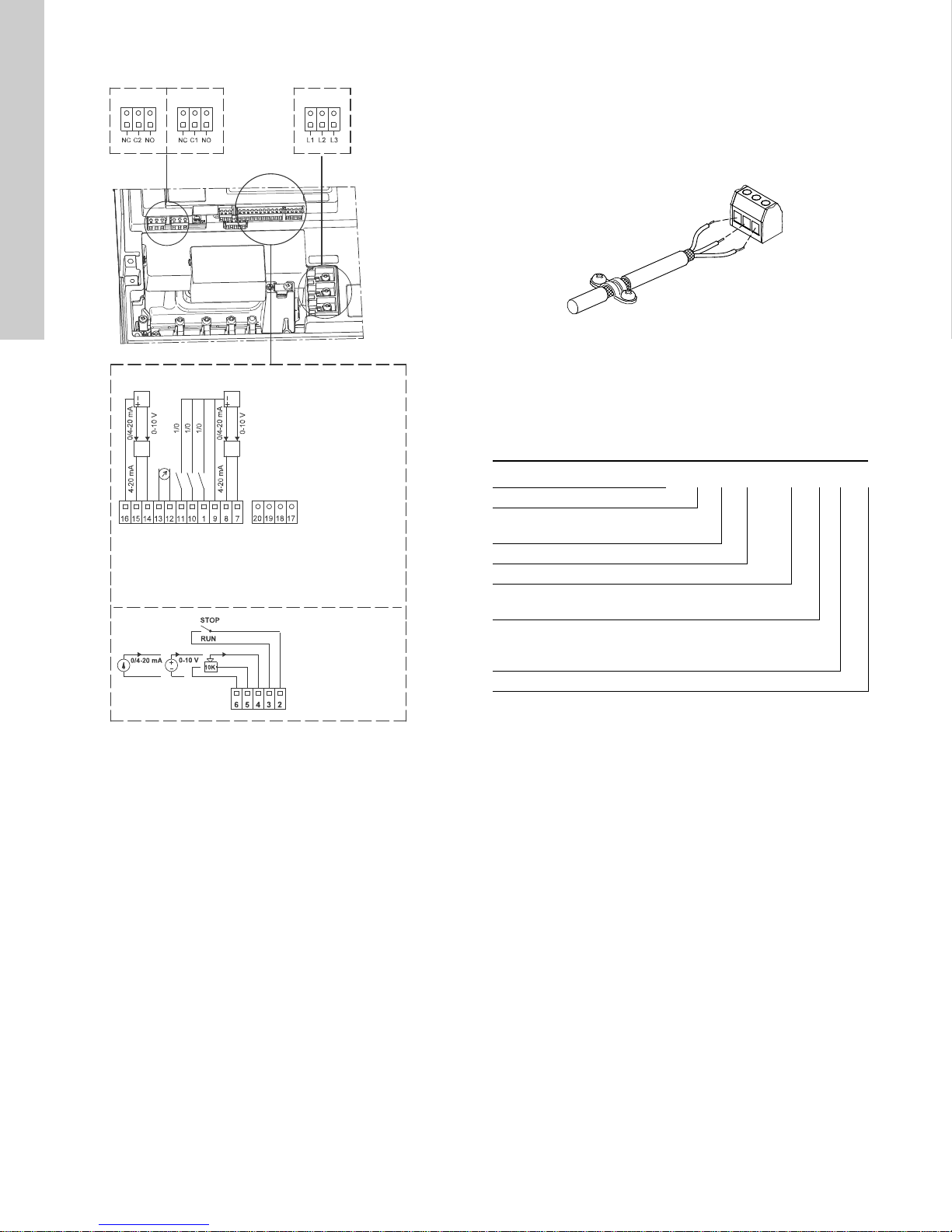
English (US)
6: GND (frame)
5: +10 V
4: Setpoint input
3: GND (frame)
2: Start/stop
Group 2
Group 3
20: PT 100 B
19: PT 100 B
18: PT 100 A
17: PT 100 A
16: GND (frame)
15: +24 V
14: Sensor input 2
13: GND
12: Analog output
11: Digital input 4
10: Digital input 3
1: Digital input 2
9: GND (frame)
8: +24 V
7: Sensor input
B: RS-485B
Y: Screen
A: RS-485A
Group 1
Group 3: Power supply (terminals L1, L2, L3)
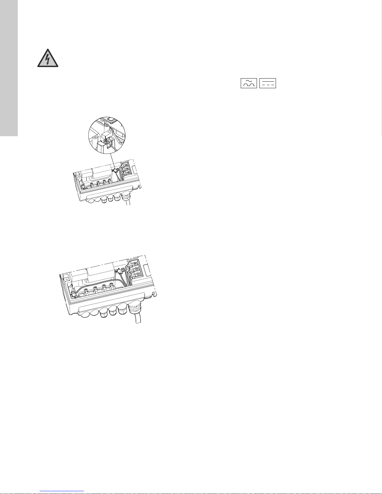
13.3 Signal cables
• Use screened cables with a conductor cross-section of min. 28
AWG and maximum 16 AWG for external On/Off switch, digital
input, setpoint and sensor signals.
• Connect the screens of the cables to frame at both ends with
good frame connection. The screens must be as close as
possible to the terminals. See fig. 17.
Fig. 17 Stripped cable with screen and wire connection
• Always tighten screws for frame connections whether a cable
is fitted or not.
• Make the wires in the pump terminal box as short as possible.
13.4 E-pump electrical connections
13.4.1 Type key
DPI +T 0-6 G 1/2" 020 E, Set
Type
Temperature sensor:
+T = with temperature Sensor
Flow range [m
Thread size
Output signal:
020 = 4-20 mA
O-ring material:
E = EPDM
F = FKM
Set = Complete pressure transmitter
3
/h]
TM02 1325 0901
Fig. 16 Connection terminals
A galvanic separation must fulfill the requirements for reinforced
insulation including creepage distances and clearances specified
in EN 61800-5-1.
26
TM05 2986 0812
Page 27

13.4.2 Electrical connections
p
Dry-running sensor
Set to automatic resetting
Connection terminals on E-pump:
2 (Start/Stop) and 3 (GND)
3
2
1 x 200-240 VAC or
1 x 80-130 VAC
Jumper cable
Brown
Black
Blue
White
PIN 123 4
Fig. 18 Electrical connections
13.4.3 Connection of E-pump to LiqTec
2
1
4
Wire color Brown Grey Blue Black
Output
4-20 mA
Output
2 x 0-10 V
+ Not used - Not used
Pressure
+
signal
-*
Temperature
signal
English (US)
* Common ground for both pressure and temperature signal.
3
* Power supply (screened cable): SELV or PELV.
* Grundfos will not be liable for damage or wear to products
TM04 7156 1610
caused by abnormal operating conditions, accident abuse,
misuse unauthorized alteration or repair, or if the product was
not installed in accordance with Grundfos' printed installation
and operating instructions. Splicing of the supplied cable
would void any warranty.
Fig. 19 Connection of E-pump to LiqTec
TM03 0437 5104
27
Page 28
English (US)
Pump
Pump
Q
H
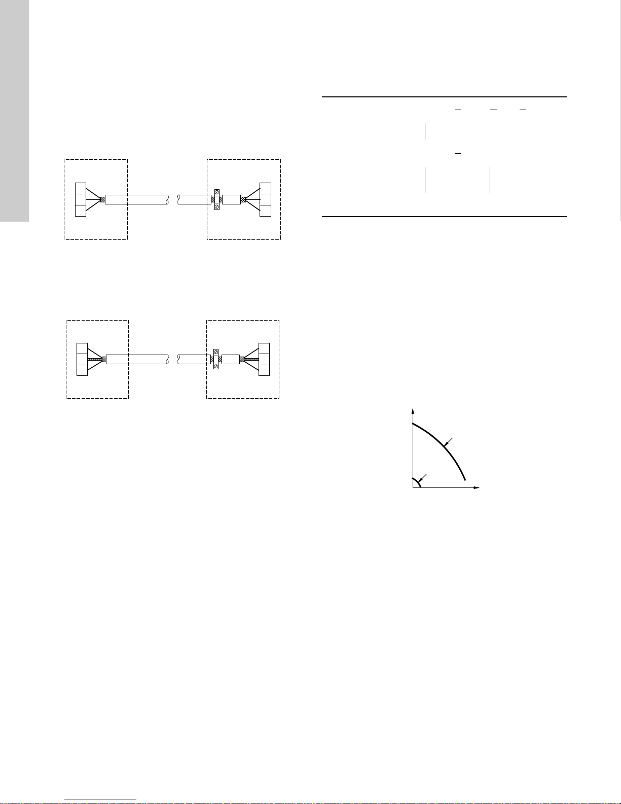
13.5 Bus connection cable
13.5.1 New installations
For the bus connection, use a screened 3-core cable with a
conductor cross-section of 28-16 AWG.
• If the pump is connected to a unit with a cable clamp which is
identical to the one on the pump, connect the screen to this
cable clamp.
• If the unit has no cable clamp as shown in fig. 20, leave the
screen unconnected at this end.
14. Modes
Grundfos E-pumps are set and controlled according to operating
and control modes.
14.1 Overview of modes
Operating modes Normal Stop Min. Max.
Control modes Uncontrolled Controlled
A
1
2
Y
3
B
A
1
2
Y
3
B
Fig. 20 Connection with screened 3-core cable
13.5.2 Replacing an existing pump
• If a screened 2-core cable is used in the existing installation,
connect it as shown in fig. 21.
A
1
Y
2
B
A
1
Y
2
B
Fig. 21 Connection with screened 2-core cable
• If a screened 3-core cable is used in the existing installation,
follow the instructions in section 13.5.1 New installations.
Constant
curve
1)
For this control mode the pump is equipped with a pressure
TM02 8841 0904TM02 8842 0904
sensor. The pump may also be equipped with a temperature
sensor in which case the description would be constant
Constant
pressure
1)
temperature in control mode controlled.
14.2 Operating mode
When the operating mode is set to Normal, the control mode can
be set to controlled or uncontrolled. See section 14.3 Control
mode.
The other operating modes that can be selected are Stop, Min. or
Max.
• Stop: the pump has been stopped
• Min.: the pump is operating at its minimum speed
• Max.: the pump is operating at its maximum speed.
Figure 22 is a schematic illustration of minimum and maximum
curves.
Max.
Min.
TM00 5547 0995
Fig. 22 Minimum and maximum curves
The maximum curve can for instance be used in connection with
the venting procedure during installation.
The minimum curve can be used in periods in which a minimum
flow is required.
If the power supply to the pump is disconnected, the mode setting
will be stored.
The Grundfos GO and R100 offer additional possibilities of
setting and status displays. See section 17. Setting by means of
R100 for setting by means of R100. See section 17.6 Grundfos
GO Remote for setting by means of Grundfos GO.
28
Page 29
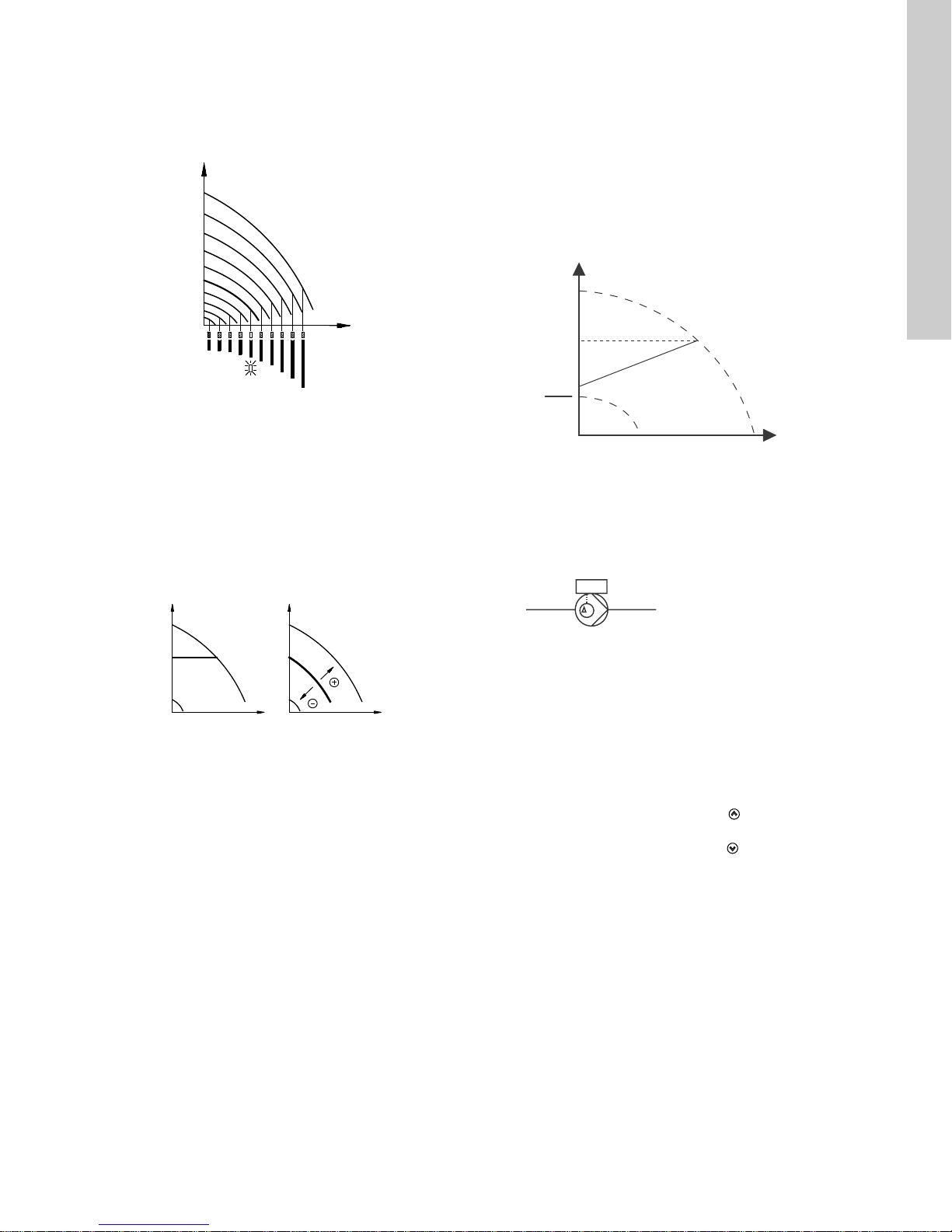
14.3 Control mode
H
Q
Q
H
set
H
Q
H
UncontrolledControlled
H
Q
Hset
Hset
2
p
14.3.1 Pumps without factory-fitted sensor
The pumps are factory-set to control mode uncontrolled.
In control mode uncontrolled, the pump will operate according to
the constant curve set, fig. 23.
Fig. 23 Pump in control mode uncontrolled (constant curve)
16. Setting by means of control panel
Proportional pressure
The pump head is reduced at decreasing water demand and
increased at rising water demand. See fig. 25.
This control mode is especially suitable in systems with relatively
large pressure losses in the distribution pipes. The head of the
pump will increase proportionally to the flow in the system to
compensate for the large pressure losses in the distribution
pipes.
The setpoint can be set with an accuracy of 0.33 ft (0.1 m). The
head against a closed valve is half the setpoint, H
TM00 7746 1304TM00 7668 0404
set
English (US)
.
14.3.2 Pumps with pressure sensor
The pump can be set to one of two control modes, i.e. controlled
and uncontrolled, fig. 24.
In control mode controlled, the pump will adjust its performance,
i.e. pump discharge pressure, to the desired setpoint for the
control parameter.
In control mode uncontrolled, the pump will operate according to
the constant curve set.
Fig. 24 Pump in control mode controlled (constant pressure)
or uncontrolled (constant curve)
15. Setting up the pump
15.1 Factory setting
Pumps without factory-fitted sensor
The pumps have been factory-set to control mode uncontrolled.
The setpoint value corresponds to 100 % of the maximum pump
performance (see data sheet for the pump).
Pumps with pressure sensor
The pumps have been factory-set to control mode controlled.
The setpoint value corresponds to 50 % of the sensor measuring
range (see sensor nameplate).
TM05 7909 1613
Fig. 25 Proportional pressure
This control mode requires a factory-fitted differential-pressure
sensors as shown in the example below:
Example
• Factory-fitted differential-pressure sensor.
Fig. 26 Proportional pressure
16.1 Setting of operating mode
Settings available:
•Normal
•Stop
•Min.
•Max.
Start/stop of pump
Start the pump by continuously pressing until the desired
setpoint is indicated. This is operating mode Normal.
Stop the pump by continuously pressing until none of the light
fields are activated and the green indicator light flashes.
29
Page 30

English (US)
H
Q
H
Q
0
6
3
[bar]
H
Q
Setting to Minimum
Press
pump (bottom light field flashes). When the bottom light field is
on, press for 3 seconds until the light field starts flashing.
To return to uncontrolled or controlled operation, press
continuously until the desired setpoint is indicated.
Setting to Maximum
Press continuously to change to the maximum curve of the
pump (top light field flashes). When the top light field is on, press
To return to uncontrolled or controlled operation, press
continuously until the desired setpoint is indicated.
continuously to change to the minimum curve of the
Fig. 27 Minimum curve duty
for 3 seconds until the light field starts flashing.
16.2.2 Pump in control mode uncontrolled
Example
In control mode uncontrolled, the pump performance is set within
the range from minimum to maximum curve. See fig. 30.
TM00 7346 1304TM00 7345 1304TM00 7743 0904
TM00 7746 1304TM02 0936 0501
Fig. 30 Pump performance setting, control mode uncontrolled
17. Setting by means of R100
The pump is designed for wireless communication with Grundfos
remote control R100.
Fig. 31 R100 communicating with the pump via infra-red light
Fig. 28 Maximum curve duty
16.2 Setpoint setting
Set the desired setpoint by pressing the button or .
The light fields on the control panel will indicate the setpoint set.
See examples in sections 16.2.1 Pump in control mode controlled
(pressure control) and 16.2.2 Pump in control mode uncontrolled.
16.2.1 Pump in control mode controlled (pressure control)
Example
Figure 29 shows that the light fields 5 and 6 are activated,
indicating a desired setpoint of 43 psi (3 bar). The setting range is
equal to the sensor measuring range (see sensor nameplate).
Fig. 29 Setpoint set to 3 bar, pressure control
During communication, the R100 must be pointed at the control
panel. When the R100 communicates with the pump, the red
indicator light will flash rapidly. Keep pointing the R100 at the
control panel until the red LED diode stops flashing.
The R100 offers setting and status displays for the pump.
The displays are divided into four parallel menus (see fig. 39):
0. GENERAL (see operating instructions for the R100)
1. OPERATION
2. STATUS
3. INSTALLATION
The figure above each individual display in fig. 39 refers to the
section in which the display is described.
30
Page 31

0. GENERAL 1. OPERATION 2. STATUS 3. INSTALLATION
17.1.1 17.2.1 17.3.1 17.3.7
17.1.2 17.2.2 17.3.2 17.3.7
17.1.3 17.2.3 17.3.3 17.3.8
17.1.3 (1) 17.2.4 17.3.4 (3) 17.3.9 (1)
17.1.4 17.2.5 17.3.4 - 1 (2) 17.3.10
English (US)
17.2.6 17.3.4 - 2 (2) 17.3.11 (1)
17.1.4 (1) 17.2.7 (2) 17.3.5 17.3.12
17.2.8 (2) 17.3.6 17.3.13 (1)
17.2.9 (1) 17.3.7 17.3.14 (1)
(1) This display only appears for three-phase pumps, 1.5 - 30 hp.
(2) This display only appears for three-phase pumps, 15-30 hp.
(3) This display only appears for three-phase pumps, 1.5 - 10 hp.
17.3.7 17.3.15 (1)
31
Page 32

English (US)
Displays in general
In the following explanation of the functions, one or two displays
are shown.
One display
Pumps without or with factory-fitted sensor have the same
function.
Two displays
Pumps without or with factory-fitted pressure sensor have
different functions and factory settings.
17.1 Menu OPERATION
The first display in this menu is this:
17.1.1 Setpoint
Without sensor
(uncontrolled)
Setpoint set
Actual setpoint
Actual value
Set the setpoint in %.
In control mode uncontrolled, the setpoint is set in % of the
maximum performance. The setting range will lie between the
minimum and maximum curves.
In control mode controlled, the setting range is equal to the
sensor measuring range.
If the pump is connected to an external setpoint signal, the value
in this display will be the maximum value of the external setpoint
signal. See section 21. External setpoint signal.
Setpoint and external signal
The setpoint cannot be set if the pump is controlled via external
signals (Stop, Min. curve or Max. curve). R100 will give this
warning: External control!
Check if the pump is stopped via terminals 2-3 (open circuit) or
set to min. or max. via terminals 1-3 (closed circuit).
See fig. 40.
Setpoint and bus communication
The setpoint cannot be set either if the pump is controlled from an
external control system via bus communication. R100 will give
this warning: Bus control!
To override bus communication, disconnect the bus connection.
See fig. 40.
With pressure sensor
(controlled)
Setpoint set
Actual setpoint
Actual value
Set the desired pressure in
bar.
17.1.2 Operating mode
Set one of the following operating modes:
• Normal (duty)
•Stop
•Min.
•Max.
The operating modes can be set without changing the setpoint
setting.
17.1.3 Fault indications
In E-pumps, faults may result in two types of indication: alarm or
warning.
An "alarm" fault will activate an alarm indication in R100 and
cause the pump to change operating mode, typically to stop.
However, for some faults resulting in alarm, the pump is set to
continue operating even if there is an alarm.
A "warning" fault will activate a warning indication in R100, but
the pump will not change operating or control mode.
The indication, Warning, only applies to three-phase
pumps.
Alarm
In case of alarm, the cause will appear in this display.
Possible causes:
• No alarm indication
• Too high motor temperature
• Undervoltage
• Mains voltage asymmetry (15-30 hp)
•Overvoltage
• Too many restarts (after faults)
• Overload
• Underload
• Sensor signal outside signal range
• Setpoint signal outside signal range
• External fault
• Duty/standby, communication fault
• Dry running
• Other fault.
If the pump has been set up to manual restart, an alarm indication
can be reset in this display if the cause of the fault has
disappeared.
32
Page 33

Warning (only three-phase pumps)
In case of warning, the cause will appear in this display.
Possible causes:
• No warning indication.
• Sensor signal outside signal range.
• Relubricate motor bearings, see section 27.2 Relubrication of
motor bearings.
• Replace motor bearings, see section 27.3 Replacement of
motor bearings.
• Replace varistor, see section 27.4 Replacement of varistor
(only 15-30 hp).
A warning indication will disappear automatically once the fault
has been remedied.
17.1.4 Fault log
For both fault types, alarm and warning, the R100 has a log
function.
Alarm log
17.2 Menu STATUS
The displays appearing in this menu are status displays only. It is
not possible to change or set values.
The displayed values are the values that applied when the last
communication between the pump and the R100 took place. If a
status value is to be updated, point the R100 at the control panel
and press "OK". If a parameter, e.g. speed, should be called up
continuously, press "OK" constantly during the period in which the
parameter in question should be monitored.
The tolerance of the displayed value is stated under each display.
The tolerances are stated as a guide in % of the maximum values
of the parameters.
17.2.1 Actual setpoint
Without sensor
(uncontrolled)
Tolerance: ± 2 %. Tolerance: ± 2 %.
This display shows the actual setpoint and the external setpoint in
% of the range from minimum value to the setpoint set. See
section 21. External setpoint signal.
17.2.2 Operating mode
With pressure sensor
(controlled)
English (US)
In case of "alarm" faults, the last five alarm indications will appear
in the alarm log. "Alarm log 1" shows the latest fault, "Alarm log 2"
shows the latest fault but one, etc.
The example above gives this information:
• the alarm indication Undervoltage
• the fault code (73)
• the number of minutes the pump has been connected to the
power supply after the fault occurred, 8 min.
Warning log
In case of "warning" faults, the last five warning indications will
appear in the warning log. "Warning log 1" shows the latest fault,
"Warning log 2" shows the latest fault but one, etc.
The example above gives this information:
• the warning indication Relubricate motor bearings
• the fault code (240)
• the number of minutes the pump has been connected to the
power supply since the fault occurred, 30 min.
This display shows the actual operating mode (Normal (duty),
Stop, Min., or Max.). Furthermore, it shows where this operating
mode was selected (R100, Pump, Bus, External or Stop func.).
For further details about the stop function (Stop func.), see
section 17.3.8 Stop function.
17.2.3 Actual value
Without sensor
(uncontrolled)
This display shows the value actually measured by a connected
sensor.
If no sensor is connected to the pump, "-" will appear in the
display.
With pressure sensor
(controlled)
33
Page 34

English (US)
17.2.4 Speed
17.2.8 Time until relubrication of motor bearings
Tolerance: ± 5 %
The actual pump speed will appear in this display.
17.2.5 Power input and power consumption
Tolerance: ± 10 %
This display shows the actual pump input power from the power
supply. The power is displayed in W or kW.
The pump power consumption can also be read from this display.
The value of power consumption is an accumulated value
calculated from the pump's birth and it cannot be reset.
17.2.6 Operating hours
Tolerance: ± 2 %
The value of operating hours is an accumulated value and cannot
be reset.
17.2.7 Lubrication status of motor bearings (only 15-30 hp)
This display shows how many times the motor bearings have
been relubricated and when to replace the motor bearings.
When the motor bearings have been relubricated, confirm this
action in the INSTALLATION menu.
See section 17.3.14 Confirming relubrication/replacement of
motor bearings (only three-phase pumps). When relubrication is
confirmed, the figure in the above display will be increased by
one.
This display shows when to relubricate the motor bearings. The
controller monitors the operating pattern of the pump and
calculates the period between bearing relubrications. If the
operating pattern changes, the calculated time until relubrication
may change as well.
The displayable values are these:
• in 2 years
• in 1 year
• in 6 months
• in 3 months
• in 1 month
• in 1 week
•Now!
17.2.9 Time until replacement of motor bearings
When the motor bearings have been relubricated a prescribed
number of times stored in the controller, the display in section
17.2.8 Time until relubrication of motor bearings will be replaced
by the display below.
This display shows when to replace the motor bearings. The
controller monitors the operating pattern of the pump and
calculates the period between bearing replacements.
The displayable values are these:
• in 2 years
• in 1 year
• in 6 months
• in 3 months
• in 1 month
• in 1 week
•Now!
34
Page 35

17.3 Menu INSTALLATION
p
t
L L
2
[ft]
't
L
2
[ft]
t
L
2
[ft]
17.3.1 Control mode
Without sensor
(uncontrolled)
With pressure sensor
(controlled)
System/application
Q
Heating
systems
K
p
Cooling
1)
systems
2)
0.5 0.5
T
i
English (US)
Select one of the following
control modes (see fig. 24):
• Controlled
• Uncontrolled.
Select one of the following
control modes (see fig. 24):
• Controlled
• Uncontrolled.
If the pump is connected to a bus, the control mode
cannot be selected via remote control. See section
22. Bus signal.
17.3.2 Controller
E-pumps have a factory default setting of gain (K
time (T
). However, if the factory setting is not the optimum
i
setting, the gain and the integral time can be changed in the
) and integral
p
display below.
• The gain (K
• The integral time (T
3600 s. If 3600 s is selected, the controller will function as a P
) can be set within the range from 0.1 to 20.
p
) can be set within the range from 0.1 to
i
controller.
• Furthermore, it is possible to set the controller to inverse
control, meaning that if the setpoint is increased, the speed
will be reduced. In the case of inverse control, the gain (K
must be set within the range from -0.1 to -20.
The table below shows the suggested controller settings:
0.5 -0.5 10 + 1.5L
0.5 10 + 1.5L
0.5 -0.5 30 + 1.5L
2
2
2
+2.5 100
1)
Heating systems are systems in which an increase in pump
performance will result in a rise in temperature at the sensor.
2)
Cooling systems are systems in which an increase in pump
performance will result in a drop in temperature at the
sensor.
)
p
L
= Distance in [ft] between pump and sensor
1
= Distance in [ft] between heat exchanger and sensor
L
2
K
p
System/application
Heating
systems
1)
Cooling
systems
0.5 0.5
'p
[ft]
L
1
'p
0.5
0.5 0.5
2)
< 16.4 ft:
L
1
0.5
L
> 16.4 ft:
1
L
> 32.8 ft:
1
T
i
3
5
35
Page 36

English (US)
How to set the PI controller
For most applications, the factory setting of the controller
constants K
However, in some applications an adjustment of the controller
and Ti will ensure optimum pump operation.
p
may be needed.
Proceed as follows
1. Increase the gain (K
Instability can be seen by observing if the measured value
) until the motor becomes unstable.
p
starts to fluctuate. Furthermore, instability is audible as the
motor starts hunting up and down.
Some systems, such as temperature controls, are slowreacting, meaning that it may be several minutes before the
motor becomes unstable.
2. Set the gain (K
unstable. This is the correct setting of the gain.
3. Reduce the integral time (T
) to half of the value which made the motor
p
) until the motor becomes
i
unstable.
4. Set the integral time (T
) to twice the value which made the
i
motor unstable. This is the correct setting of the integral time.
General rules of thumb
• If the controller is too slow-reacting, increase K
.
p
• If the controller is hunting or unstable, dampen the system by
reducing K
or increasing Ti.
p
17.3.3 External setpoint
17.3.4 Signal relay
Pumps of 3-10 hp have one signal relay. The factory setting of the
relay will be Fault.
Pumps of 15-30 hp have two signal relays. Signal relay 1 is
factory set to Alarm and signal relay 2 to Warning.
In one of the displays below, select in which one of three or six
operating situations the signal relay should be activated.
3-10 hp
• Ready
• Fault
• Operation
• Pump running (only three-phase pumps, 3-10 hp)
• Warning (only three-phase pumps, 3-10 hp).
15-30 hp 15-30 hp
The input for external setpoint signal can be set to different signal
types.
Select one of the following types:
•0-10 V
•0-20 mA
•4-20 mA
• Not active.
If Not active is selected, the setpoint set by means of the R100 or
on the control panel will apply.
If one of the signal types is selected, the actual setpoint is
influenced by the signal connected to the external setpoint input.
See section 21. External setpoint signal.
• Ready
•Alarm
• Operation
• Pump running
• Warning
• Relubricate.
•Ready
•Alarm
• Operation
• Pump running
• Warning
• Relubricate.
Fault and Alarm cover faults resulting in Alarm.
Warning covers faults resulting in Warning.
Relubricate covers only that one individual event.
For distinction between alarm and warning, see
section 17.1.3 Fault indications.
For further information, see section 24. Indicator lights and signal
relay.
36
Page 37

17.3.5 Buttons on pump
The operating buttons and on the control panel can be set
to these values:
•Active
• Not active.
When set to Not active (locked), the buttons do not function. Set
the buttons to Not active if the pump should be controlled via an
external control system.
17.3.6 Pump number
A number between 1 and 64 can be allocated to the pump. In the
case of bus communication, a number must be allocated to each
pump.
17.3.7 Digital inputs
The digital inputs of the pump can be set to different functions.
Select one of the following functions:
• Min. (min. curve)
• Max. (max. curve)
• External fault
• Flow switch
• Dry running (from external sensor) (only three-phase pumps).
The selected function is activated by closing the contact between
terminals 1 and 9, 1 and 10 or 1 and 11.
See also section 20.2 Digital input.
Min.
When the input is activated, the pump will operate according to
the minimum curve.
Max.
When the input is activated, the pump will operate according to
the maximum curve.
External fault
When the input is activated, a timer will be started. If the input is
activated for more than 5 seconds, the pump will be stopped and
a fault will be indicated. If the input is deactivated for more than 5
seconds, the fault condition will cease and the pump can only be
restarted manually by resetting the fault indication.
Flow switch
When this function is selected, the pump will be stopped when a
connected flow switch detects low flow.
It is only possible to use this function if the pump is connected to
a pressure sensor.
If the input is activated for more than 5 seconds, the stop function
incorporated in the pump will take over. See section 17.3.8 Stop
function.
Dry running
When this function is selected, lack of inlet pressure or water
shortage can be detected. This requires the use of an accessory,
such as these:
• a Grundfos Liqtec
• a pressure switch installed on the suction side of a pump
• a float switch installed on the suction side of a pump.
When lack of inlet pressure or water shortage (Dry running) is
detected, the pump will be stopped. The pump cannot restart as
long as the input is activated.
®
dry-running sensor
English (US)
37
Page 38

English (US)
Stop pressure
˂H
Start pressure
H
Q
Pressure sensor
Diaphragm tank
Check valve
Pump
Diaphragm tank
Pressure sensor
Pump Check valve
17.3.8 Stop function
The stop function can be set to these values:
•Active
• Not active.
When the stop function is active, the pump will be stopped at very
low flows. The controller will stop the pump to protect the pump
as follows:
• avoid unnecessary heating of the pumped liquid
• reduce wear of the shaft seals
• reduce noise from operation.
Fig. 32 Difference between start and stop pressures ('H)
2. Flow switch
When the digital input is activated for more than 5 seconds
because there is low flow, the speed will be increased until the
stop pressure (actual setpoint + 0.5 x ˂H) is reached, and the
pump will stop. When the pressure has fallen to start pressure,
the pump will start again. If there is still no flow, the pump will
quickly reach stop pressure and stop. If there is flow, the pump
will continue operating according to the setpoint.
Operating conditions for the stop function
It is only possible to use the stop function if the system
incorporates a pressure sensor, a check valve and a diaphragm
tank.
The check valve must always be installed before the
pressure sensor. See figs 33 and 34.
TM03 8582 1907TM03 8583 1907
Fig. 33 Position of the check valve and pressure sensor in
system with suction lift operation
TM00 7744 1896
˂H is factory-set to 10 % of actual setpoint.
˂H can be set within the range from 5 % to 30 % of actual
setpoint.
Low flow can be detected in two different ways:
1. A built-in "low-flow detection function" which functions if the
digital input is not set up for flow switch.
2. A flow switch connected to the digital input.
1. Low-flow detection function
The pump will check the flow regularly by reducing the speed for
a short time. If there is no or only a small change in pressure, this
means that there is low flow. The speed will be increased until the
stop pressure (actual setpoint + 0.5 x ˂H) is reached and the
pump will stop. When the pressure has fallen to the start pressure
(actual setpoint - 0.5 x ˂H), the pump will restart.
When restarting, the pumps will react differently according to
pump type:
Three-phase pumps
1. If the flow is higher than the low-flow limit, the pump will return
to continuous operation at constant pressure.
2. If the flow is still lower than the low-flow limit, the pump will
continue in start/stop operation. It will continue in start/stop
operation until the flow is higher than the low-flow limit; when
the flow is higher than the low-flow limit, the pump will return
to continuous operation.
Fig. 34 Position of the non-return valve and pressure sensor in
system with positive inlet pressure
38
Page 39

Diaphragm tank
The stop function requires a diaphragm tank of a certain minimum
size. The tank must be installed immediately after the pump and
the precharge pressure must be 0.7 x actual setpoint.
Recommended diaphragm tank size:
Rated flow rate of
pump
3
[gpm (m
/h)]
0-26
(0 - 5.9)
27-105
(6.1 - 23.8)
106-176
(24.2 - 40)
177-308
(40.2 - 70.0)
309-440
(70.2 - 99.9)
441-750
(100-170)
CRE pump
1s, 1, 3 2 (7.6)
5, 10, 15 4.4 (16.7)
20, 32 14 (53.0)
45 34 (128.7)
64, 90 62 (234.7)
120, 150 86 (325.5)
Typical diaphragm
tank size
[gal (liter)]
If a diaphragm tank of the above size is installed in the system,
the factory setting of ˂H is the correct setting.
If the tank installed is too small, the pump will start and stop too
often. This can be remedied by increasing ˂H.
17.3.9 Flow limit for the stop function
Flow limit for the stop function only works if the
system is not set up for flow switch.
In order to set at which flow rate the system is to go from
continuous operation at constant pressure to start/stop operation,
select among these four values of which three are preconfigured
flow limits:
•Low
•Normal
•High
•Custom.
The default setting of the pump is Normal, representing
approximately 10 % of the rated flow rate of the pump.
If a lower flow limit than normal is desired or the tank size is
smaller than recommended, select Low.
If a higher flow than normal is wanted or a large tank is used, set
the limit to High.
The value Custom can be seen in R100 but it can only be set by
means of the PC Tool E-products. Custom is for customized setup and optimizing to the process.
˂H
Low
Normal
High
Fig. 35 Three preconfigured flow limits, Low, Normal and High
17.3.10 Sensor
Without sensor
(uncontrolled)
With pressure sensor
(controlled)
The setting of the sensor is only relevant in the case of controlled
operation.
Select among the following values:
• Sensor output signal
0-10 V
0-20 mA
4-20 mA,
• Unit of measurement of sensor:
bar, mbar, m, kPa, psi, ft, m
3
/h, m3/s, l/s, gpm, °C, °F, %,
• Sensor measuring range.
English (US)
TM03 9060 3307
39
Page 40

English (US)
17.3.11 Duty/standby
The duty/standby function applies to two pumps connected in
parallel and controlled via GENIbus.
The duty/standby function can be set to these values:
•Active
• Not active.
When the function is set to Active, the following applies:
• Only one pump is running at a time.
• The stopped pump (standby) will automatically be cut in if the
running pump (duty) has a fault. A fault will be indicated.
• Changeover between the duty pump and the standby pump
will take place every 24 hours.
Activate the duty/standby function as follows:
1. Install and prime the two pumps according to the installation
and operating instructions supplied with the pumps.
2. Check that the power supply is connected to the first pump
according to the installation and operating instructions.
3. Use Grundfos R100 to set the duty/standby to Not active in
the installation menu.
4. Use Grundfos R100 to set the Operating mode to Stop in the
operation menu.
5. Use Grundfos R100 to set the other displays as required for
the pump application (such as setpoint).
6. Disconnect the power supply to both pumps.
7. Installation of the AYB cable (91125604):
a. Remove the plug from each MLE terminal box with a flat
head screw driver. See fig. 36.
b. Screw a new cable gland into each MLE terminal box with a
crescent wrench. See fig. 36.
c. Loosen the new cable gland caps and push the cable ends
through the cable glands and into MLE motors.
d. Remove the AYB connector plug from the first MLE motor.
See fig. 37.
e. Connect the black wire to the A terminal of the AYB
connector plug.
f. Connect the orange wire to the Y terminal of the AYB
connector plug.
g. Connect the red wire to the B terminal of the AYB connector
plug.
h. Reconnect the AYB connector plug to the first MLE motor.
i. Tighten the cable gland cap to secure the cable. See fig.
36.
j. Repeat steps d to i for the second MLE motor.
8. Connect the power supply to the two pumps according to the
installation and operation instructions.
9. Use Grundfos R100 to check that the Operating mode is set to
Normal in the operation menu of the second pump.
10. Use Grundfos R100 to set the other displays as required for
the pump application (such as Setpoint).
11. Use Grundfos R100 to set the duty/standby to Active in the
installation menu of the second pump. Please note the second
pump will search for the first pump and automatically set the
duty/standby to Active in the installation menu.
12. The second pump will operate for the first 24 hours. The two
pumps will then alternate operation every 24 hours.
PE
L3
L2
Plug
L1
Cable gland
Fig. 36 Removing the plug and connecting cable gland to the
terminal box
Fig. 37 AYB connector plug
TM05 1626 3311
TM05 2985 0812
40
Page 41

17.3.12 Operating range
H
How to set the operating range:
• Set the minimum curve within the range from maximum curve
to 12 % of maximum performance. The pump is factory-set to
24 % of maximum performance.
• Set the maximum curve within the range from maximum
performance (100 %) to minimum curve.
The area between the minimum and maximum curves is the
operating range.
100 %
Max. curve
17.3.14 Confirming relubrication/replacement of motor
bearings (only three-phase pumps)
English (US)
This function can be set to these values:
• Relubricated (only 15-30 hp)
•Replaced
• Nothing done.
When the bearing monitoring function is Active, the controller will
give a warning indication when the motor bearings are due to be
relubricated or replaced. See section 17.1.3 Fault indications.
When the motor bearings have been relubricated or replaced,
confirm this action in the above display by pressing OK.
Relubricated cannot be selected for a period of time
after confirming relubrication.
Opera
ti
Min. curve
12 %
Fig. 38 Setting of the minimum and maximum curves in % of
maximum performance
17.3.13 Motor bearing monitoring (only three-phase pumps)
The motor bearing monitoring function can be set to these values:
•Active
• Not active.
When the function is set to Active, a counter in the controller will
start counting the mileage of the bearings. See section
17.2.7 Lubrication status of motor bearings (only 15-30 hp).
The counter will continue counting even if the
function is switched to Not active, but a warning will
not be given when it is time for relubrication.
When the function is switched to Active again, the
accumulated mileage will again be used to calculate
the relubrication time.
ng ra
n
ge
17.3.15 Standstill heating (only three-phase pumps)
TM00 7747 1896
The standstill heating function can be set to these values:
•Active
• Not active.
When the function is set to Active, an AC voltage will be applied
to the motor windings. The applied voltage will ensure that
sufficient heat is generated to avoid condensation in the motor.
41
Page 42

English (US)
17.4 Typical display settings for constant-pressure E-pumps
1. OPERATION 2. STATUS 3. INSTALLATION
17.1.1 17.2.1 17.3.1 17.3.7
17.1.2 17.2.2 17.3.2 17.3.7
17.1.3 17.2.3 17.3.3 17.3.8
17.1.3 (1) 17.2.4 17.3.4 - 1 (2) 17.3.9 (1)
17.2.5 17.3.4 - 2 (2) 17.3.10
17.2.6 17.3.5 17.3.11 (1)
17.2.7 (2) 17.3.6 17.3.12
17.2.8 (2) 17.3.7 17.3.13 (1)
17.3.14 (1)
17.3.15 (1)
(1) This display only appears for three-phase pumps, 1.5 - 30 hp.
(2) This display only appears for three-phase pumps, 15-30 hp.
(3) This display only appears for three-phase pumps, 1.5 - 10 hp.
Fig. 39 Menu overview
42
Page 43

17.5 Typical display settings for analog-input E-pumps
1. OPERATION 2. STATUS 3. INSTALLATION
17.1.1 17.2.1 17.3.1 17.3.7
17.1.2 17.2.2 17.3.2 17.3.7
17.1.3 17.2.3 17.3.3 17.3.8
17.1.3 (1) 17.2.4 17.3.4 - 1 (2) 17.3.9 (1)
English (US)
17.2.5 17.3.4 - 2 (2) 17.3.10
17.2.6 17.3.5 17.3.11 (1)
17.2.7 (2) 17.3.6 17.3.12
17.2.8 (2) 17.3.7 17.3.13 (1)
17.3.14 (1)
17.3.15 (1)
(1) This display only appears for three-phase pumps, 1.5 - 30 hp.
(2) This display only appears for three-phase pumps, 15-30 hp.
(3) This display only appears for three-phase pumps, 1.5 - 10 hp.
Fig. 40 Menu overview
43
Page 44

English (US)
1
2
3
5
7
9
10
13
15 16 17 18
14
12
11
8
6
4
17.6 Grundfos GO Remote
The motor is designed for wireless radio or infrared
communication with Grundfos GO.
Grundfos GO enables setting of functions and gives access to
status overviews, technical product information and actual
operating parameters.
Grundfos GO Remote offers the following mobile interfaces (MI).
See fig. 41.
Dashboard
1
TM05 5609 3912
Fig. 42 Example of dashboard
2
+
Pos. Description Action
+
Connection
1
indicator
TM06 6256 0916
Fig. 41 Grundfos GO communicating with the motor via radio
or infrared connection (IR)
Pos. Description
Grundfos MI 204:
Add-on module enabling radio or infrared
communication. You can use MI 204 in conjunction
with an Apple iPhone or iPod touch with Lightning
1
connector, e.g. fifth generation or later iPhone or
iPod touch. MI 204 is also available together with an
Apple iPod touch and a cover.
Grundfos MI 301:
Separate module enabling radio or infrared
communication. The module can be used in
2
conjunction with an Android or iOS-based
Smartphone with Bluetooth connection.
17.6.1 Communication
When Grundfos GO Remote communicates with the pump, the
indicator light in the middle of the Grundfos Eye will flash green.
Communication must be established using one of these
communication types:
• radio communication
• infrared communication.
Radio communication
Radio communication can take place at distances up to 30
meters. It is necessary to enable communication by pressing
or on the pump control panel.
Infrared communication
When communicating via infrared light, Grundfos GO Remote
must be pointed at the pump control panel.
17.6.2 Navigation
Navigation can be done from the dashboard. See fig. 42.
2 Back button Returns to the previous display.
Product
3
information
4 Product name
Alarms and
5
warnings
6Grundfos Eye
Primary status
7
value
Secondary status
8
value
9 Control source
10 Control mode
Actual setpoint
11
value
12 Operating mode Shows the operating mode.
13 Show menu Gives access to other menus.
14 Stop Stops the product.
Tool bar
15 Help
16 Documentation
17 Report
18 Update
This text appears when Grundfos
GO Remote app has connected to an
MI 204, MI 202 or MI 301.
If the hardware is not connected, it
will not be possible to communicate
with a Grundfos product.
Provides technical information about
the product.
Name of the product communicating
with Grundfos GO Remote.
Shows alarms and warnings.
Shows the operating condition of the
product.
Shows the primary status value.
Shows the secondary status value.
Shows by which interface the
product is controlled.
Shows the control mode of the
product.
Shows the actual setpoint value.
The help function describes the
menus making it easy for the user to
change settings, etc.
Gives access to installation and
operating instructions and quick
guides.
Enables the creation of user-defined
reports.
Enables update of Grundfos GO
Remote app.
44
Page 45

18. Setting by means of PC Tool E-products
Q
H
Q
H
Special setup requirements differing from the settings available
via the GO Remote or R100 require the use of Grundfos PC Tool
E-products. This again requires the assistance of a Grundfos
service technician or engineer. Contact your local Grundfos
company for more information.
19. Priority of settings
The priority of settings depends on two factors:
1. control source
2. settings.
1. Control source
Priority of settings with bus communication
Control panel,
Priority
GO Remote or
R100
1 Stop
2 Max.
3 Stop Stop
4 Max.
5 Min.
6 Setpoint setting
External
signals
communication
Bus
English (US)
Control panel
GO Remote or R100
External signals
(external setpoint signal, digital inputs, etc.).
Communication from another control system via
bus
2. Settings
• Operating mode Stop
• Operating mode Max. (maximum curve)
• Operating mode Min. (minimum curve)
• Setpoint setting.
An E-pump can be controlled by different control sources at the
same time, and each of these sources can be set differently.
Consequently, it is necessary to set an order of priority of the
control sources and the settings.
If two or more settings are activated at the same
time, the pump will operate according to the function
with the highest priority.
Priority of settings without bus communication
Priority
1 Stop
2 Max.
Control panel, GO
Remote, or R100
External signals
Example: If the E-pump is operating according to a setpoint set
via bus communication, the control panel, GO Remote or R100
can set the E-pump to operating mode Stop or Max., and the
external signal can only set the E-pump to operating mode Stop.
20. External forced-control signals
The pump has inputs for external signals for these forced-control
functions:
• Start/stop of pump
• Digital function.
20.1 Start/stop input
Functional diagram: Start/stop input
Start/stop (term inal s 2 and 3)
Normal duty
Stop
3 Stop
4 Max.
5 Min. Min.
6 Setpoint setting Setpoint setting
Example: If the E-pump has been set to operating mode Max.
(Max. frequency) via an external signal, such as digital input, the
control panel or GO Remote or R100 can only set the E-pump to
operating mode Stop.
45
Page 46

English (US)
Q
H
Q
H
Q
H
Q
H
5 s
delay
Q
H
5 s
5 s
delay
Q
H
0 10 V
0 20 mA
4 20 mA
Actual setpoint
Sensor
max
Setpoint set by means of
control panel, or PC Tool
E-products
Sensor
min
External setpoint signal
Actual
setpoint
0 10 V
0 20 mA
4 20 mA
Actual setpoint
Maximum curve
Setpoint set by means of
control panel, R100 or PC Tool
E-products
Minimum curve
External setpoint signal
Actual
setpoint
20.2 Digital input
One of the following functions can be selected for the digital
input:
• Normal duty
• Minimum curve
• Maximum curve
• External fault
• Flow switch
• Dry running.
Functional diagram: Input for digital function
In control mode controlled, the setpoint can be set externally
within the range from the lower value of the sensor measuring
range to the setpoint set on the pump or by means of the GO
Remote or R100.
(terminals 1 and 9) (terminals 9 and 10) (terminals 9 and 11)
Digital function
Normal duty
Min. curve
Max. curve
External fault
Flow switch
Dry running
Fig. 44 Relation between the actual setpoint and the external
setpoint signal in control mode controlled
Example: At a sensor
and an external setpoint of 80 % (an 8 V analog signal to Terminal
value of 0 psi, a setpoint set of 50 psi
min
4 if using an analog signal of 0-10 V), the actual setpoint will be
as follows:
Actual
setpoint
= (setpoint - sensor
min
) x %
external setpoint
+ sensor
min
= (50 - 0) x 80 % + 0
=40 psi
In control mode uncontrolled, the setpoint can be set externally
within the range from the min. curve to the setpoint set on the
pump or by means of the GO Remote or R100. Typically the
setpoint is set to 100 % when the control mode is uncontrolled
(see section 17.5 Typical display settings for analog-input E-
pumps.
TM02 8988 1304
21. External setpoint signal
The setpoint can be remote-set by connecting an analogue signal
transmitter to the input for the setpoint signal (terminal 4).
Setpoint
External setpoint
Fig. 43 Actual setpoint as a product (multiplied value) of
setpoint and external setpoint
Select the actual external signal, 0-10 V, 0-20 mA, 4-20 mA, via
the GO Remote or R100. See section 17.3.3 External setpoint.
If control mode uncontrolled is selected by means of the GO
Remote or R100, the pump can be controlled by any controller.
46
Actual setpoint
TM03 8601 2007
TM02 8988 1304
Fig. 45 Relation between the actual setpoint and the external
setpoint signal in control mode uncontrolled
Page 47

22. Bus signal
Green
Red
The pump supports serial communication via an RS-485 input.
The communication is carried out according to Grundfos bus
protocol, GENIbus protocol, and enables connection to a building
management system or another external control system.
Operating parameters, such as setpoint, operating mode, etc. can
be remote-set via the bus signal. At the same time, the pump can
provide status information about important parameters, such as
actual value of control parameter, input power, fault indications,
etc.
Contact Grundfos for further details.
If a bus signal is used, the number of settings
available via the GO Remote will be reduced.
23. Other bus standards
Grundfos offers various bus solutions with communication
according to other standards.
Contact Grundfos for further details.
24. Indicator lights and signal relay
The operating condition of the pump is indicated by the green and
red indicator lights fitted on the pump control panel and inside the
terminal box. See fig. 46.
English (US)
Green
Red
Green Red
TM02 8513 0304
Fig. 46 Position of indicator lights
In addition, the pump incorporates an output for a potential-free
signal via an internal relay.
For signal relay output values, see section 17.3.4 Signal relay.
TM02 9036 4404
TM03 9063 3307
47
Page 48

English (US)
NCNOCNCNOCNCNOCNCNO
C
NCNO
C
C
NO NCCNO NCCNO NC
NCNO
C
C
NO NCCNO NC
NCNO
C
NCNOCNCNO
C
C
NO NC
NCNO
C
C
NO NC
NCNOCNCNOCNCNO
C
C
NO NCCNO NCCNO NCCNO NC
C
NO NC
NCNO
C
C
NO NC
NCNO
C
The functions of the two indicator lights and the signal relay are as shown in the following table:
Indicator lights Signal relay activated during
Fault (red)
Operation
(green)
Fault/Alarm,
Warning
and
Operating Ready
Pump
running
Description
Relubricate
Off Off The power supply has been switched off.
Off
Off
Permanently
on
Permanently
on
The pump is operating.
The pump is stopped by the stop function.
Off Flashing The pump has been set to stop.
The pump has stopped because of a Fault/
Alarm or is running with a Warning or
Relubricate indication.
Permanently
on
Off
If the pump was stopped, restarting will be
attempted (it may be necessary to restart the
pump by resetting the Fault indication).
If the cause is "external fault", the pump must
be restarted manually by resetting the Fault
indication.
The pump is operating, but it has or has had a
Fault/Alarm allowing the pump to continue
operation or it is operating with a Warning or
Relubricate indication.
If the cause is "sensor signal outside signal
range", the pump will continue operating
Permanently onPermanently
on
according to the 70 % curve and the fault
indication cannot be reset until the signal is
inside the signal range.
If the cause is "setpoint signal outside signal
range", the pump will continue operating
according to the min. curve and the fault
indication cannot be reset until the signal is
inside the signal range.
Permanently
on
Flashing
Resetting of fault indication
A fault indication can be reset in one of the following ways:
• Briefly press the button or on the pump. This will not
change the setting of the pump.
A fault indication cannot be reset by means of or if the
buttons have been locked.
• Switch off the power supply until the indicator lights are off.
• Switch the external start/stop input off and then on again.
• Use the GO Remote or R100. See section 17.1.3 Fault
indications.
When the GO Remote or R100 communicates with the pump, the
red indicator light will flash rapidly.
48
The pump has been set to stop, but it has been
stopped because of a fault.
Page 49

25. Emergency operation (only 15-30 hp)
DANGER
Electric shock
Death or serious personal injury
- Disconnect all electric supply circuits and ensure
these have been switched off for at least 5 minutes
before making any connections in the pump
terminal box. For instance, the signal relay may be
connected to an external supply which is still
connected when the power supply is
disconnected.
If the pump is stopped and you cannot start the pump
immediately after normal remedies, the reason could be a faulty
variable frequency drive. If this is the case it is possible to
maintain emergency operation of the pump.
Before change over to emergency operation we recommend that
you:
• check that the power supply is OK
• check that control signals are working (start/stop signals)
• check that all alarms are reset
• make a resistance test on the motor windings (disconnect the
motor leads from the terminal box).
If the pump remains stopped it is possible that the variable
frequency drive is faulty.
To establish emergency operation proceed as follows:
1. Disconnect the three power supply leads, L1, L2, L3, from the
terminal box, but leave the protective ground lead(s) in
position on the PE terminal(s).
2. Disconnect the motor supply leads, U/W1, V/U1, W/V1, from
the terminal box.
English (US)
TM03 9120 3407TM04 0018 4807TM03 9121 3407
3. Connect the leads as shown in fig. 47.
Fig. 47 How to switch an E-pump from normal operation to
emergency operation
Use the screws from the power supply terminals and the nuts
from the motor terminals.
TM03 8607 2007
49
Page 50

English (US)
4. Insulate the three leads from each other by means of
insulating tape or similar means.
27. Maintaining and servicing the motor
27.1 Cleaning of the motor
Keep the motor cooling fins and fan blades clean to ensure
sufficient cooling of the motor and electronics.
27.2 Relubrication of motor bearings
3-10 hp pumps
The motor bearings are of the closed type and greased for life.
TM03 9122 3407
The bearings cannot be relubricated.
15-30 hp pumps
The motor bearings are of the open type and must be relubricated
regularly. The motor bearings are prelubricated on delivery. The
built-in bearing monitoring function will give a warning indication
on the GO Remote or R100 when the motor bearings are due to
be relubricated.
DANGER
Electric shock
Death or serious personal injury
- Do not bypass the variable frequency drive by
connecting the power supply leads to the U, V and
W terminals. This may cause hazardous situations
for personnel as the high voltage potential of the
power supply may be transferred to touchable
components in the terminal box.
Check the direction of rotation when starting up after
switching to emergency operation.
5. A motor starter is required.
26. Insulation resistance
3-10 hp
Do not measure the insulation resistance of motor
windings or an installation incorporating E-pumps
using high voltage megging equipment, as this may
damage the built-in electronics.
15-30 hp
Do not measure the insulation resistance of an
installation incorporating E-pumps using high
voltage megging equipment, as this may damage
the built-in electronics.
The motor leads can be disconnected separately
and the insulation resistance of the motor windings
can be tested.
TM03 9123 3407
When relubricating the first time, use the double quantity of
grease as the lubricating channel is still empty.
The recommended grease type is a polycarbamide-based
lubricating grease.
Before relubrication, remove the bottom plug in the
motor flange and the plug in the bearing cover to
ensure that old and excess grease can escape.
Quantity of grease
Frame size
Drive end
(DE)
MLE 160 0.44 0.44
MLE 180 0.51 0.51
[ounces]
Non-drive end
27.3 Replacement of motor bearings
Motors from 15-30 hp have built-in bearing monitoring function
which will give a warning indication on the Grundfos GO Remote
or R100 when the motor bearings are due to be replaced.
(NDE)
50
Page 51

27.4 Replacement of varistor (only 15-30 hp)
The varistor protects the pump against voltage transients. If
voltage transients occur, the varistor will be worn over time and
need to be replaced. The more transients, the more quickly the
varistor will be worn. When it is time to replace the varistor,
Grundfos GO, R100 and PC Tool E-products will indicate this as a
warning.
A Grundfos technician is required for replacement of the varistor.
Contact your local Grundfos company for assistance.
27.5 Service parts and service kits
For further information on service parts and service kits, visit
www.grundfos.com, select country, select WebCAPS.
28. Technical data
28.1 Technical data - thre e-phase pumps, 3-10 hp
28.1.1 Supply voltage
3 x 440-480 V - 10 %/+ 10 %, 60 Hz - 2 %/+ 2 %, PE.
3 x 208-230 V - 10 %/+ 10 %, 60 Hz - 2 %/+ 2 %, PE.
Cable: Max 10 mm
Use min. 158 °F (70 °C) copper conductors only.
Recommended fuse sizes
Motor sizes from 3 to 7.5 hp: Max. 16 A.
Motor size 10 hp: Max. 32 A.
Standard as well as quick-blow or slow-blow fuses may be used.
28.1.2 Overload protection
The overload protection of the E-motor has the same
characteristic as an ordinary motor protector. As an example, the
E-motor can stand an overload of 110 % of I
28.1.3 Leakage current
3 hp (supply voltage < 460 V)
3 hp (supply voltage > 460 V)
The leakage currents are measured in accordance with EN
61800-5-1.
2
/ 8 AWG.
for 1 min.
nom
Motor size
[hp]
Leakage current
[mA]
< 3.5
< 5
5 to 7.5 hp < 5
10 hp < 10
28.1.4 Inputs/output
Start/stop
External potential-free contact.
Voltage: 5 VDC.
Current: < 5 mA.
2
Screened cable: 20-16 AWG (0.5 - 1.5 mm
).
Digital
External potential-free contact.
Voltage: 5 VDC.
Current: < 5 mA.
2
Screened cable: 20-16 AWG (0.5 - 1.5 mm
).
Setpoint signals
• Potentiometer
0-10 VDC, 10 k˖ (via internal voltage supply).
Screened cable: 20-16 AWG (0.5 - 1.5 mm
2
).
Maximum cable length: 328 ft (100 m).
• Voltage signal
0-10 VDC, R
Tolerance: + 0 %/- 3 % at maximum voltage signal.
Screened cable: 20-16 AWG (0.5 - 1.5 mm
> 50 k˖.
i
2
).
Maximum cable length: 1640 ft (500 m).
• Current signal
DC 0-20 mA / 4-20 mA, R
Tolerance: + 0 %/- 3 % at maximum current signal.
Screened cable: 20-16 AWG (0.5 - 1.5 mm
= 175 ˖.
i
2
).
Maximum cable length: 1640 ft (500 m).
Sensor signals
• Voltage signal
0-10 VDC, R
Tolerance: + 0 %/- 3 % at maximum voltage signal.
Screened cable: 20-16 AWG (0.5 - 1.5 mm
> 50 k˖ (via internal voltage supply).
i
2
).
Maximum cable length: 1640 ft (500 m).
• Current signal
DC 0-20 mA / 4-20 mA, R
Tolerance: + 0 %/- 3 % at maximum current signal.
Screened cable: 20-16 AWG (0.5 - 1.5 mm
= 175 ˖.
i
2
).
Maximum cable length: 1640 ft (500 m).
Internal power supplies
• 10 V power supply for external potentiometer:
Maximum load: 2.5 mA.
Short-circuit protected.
• 24 V power supply for sensors:
Maximum load: 40 mA.
Short-circuit protected.
Signal relay output
Potential-free changeover contact.
Maximum contact load: 250 VAC, 2 A, cos ˳ 0.3 - 1.
Minimum contact load: 5 VDC, 10 mA.
2
Screened cable: 28-12 AWG (0.5 - 2.5 mm
).
Maximum cable length: 1640 ft (500 m).
Bus input
Grundfos bus protocol, GENIbus protocol, RS-485.
Screened 3-core cable: 28-16 AWG (0.2 - 1.5 mm
Maximum cable length: 1640 ft (500 m).
English (US)
2
).
51
Page 52

English (US)
28.2 Technical data - thre e-phase pumps, 15-30 hp
28.2.1 Supply voltage
3 x 440-480 V - 10 %/+ 10 %, 60 Hz - 3 %/+ 3 %, PE.
Cable: Maximum. 8 AWG (10 mm
Use min. 158 °F (70 °C) copper conductors only.
Recommended fuse sizes
Motor size [hp] Max. [A]
15 32
20 36
25 43
30 51
Standard as well as quick-blow or slow-blow fuses may be used.
28.2.2 Overload protection
The overload protection of the E-motor has the same
characteristic as an ordinary motor protector. As an example, the
E-motor can stand an overload of 110 % of I
28.2.3 Leakage current
Ground leakage current > 10 mA.
The leakage currents are measured in accordance with EN
61800-5-1.
28.2.4 Inputs/output
Start/stop
External potential-free contact.
Voltage: 5 VDC.
Current: < 5 mA.
Screened cable: 20-16 AWG (0.5 - 1.5 mm
Digital
External potential-free contact.
Voltage: 5 VDC.
Current: < 5 mA.
Screened cable: 20-16 AWG (0.5 - 1.5 mm
Setpoint signals
• Potentiometer
0-10 VDC, 10 k˖ (via internal voltage supply).
Screened cable: 20-16 AWG (0.5 - 1.5 mm
Maximum cable length: 328 ft (100 m).
• Voltage signal
0-10 VDC, R
Tolerance: + 0 %/- 3 % at maximum voltage signal.
> 50 k˖.
i
Screened cable: 20-16 AWG (0.5 - 1.5 mm
Maximum cable length: 1640 ft (500 m).
• Current signal
DC 0-20 mA / 4-20 mA, R
Tolerance: + 0 %/- 3 % at maximum current signal.
Screened cable: 20-16 AWG (0.5 - 1.5 mm
Maximum cable length: 1640 ft (500 m).
2
)
= 250 ˖.
i
nom
2
).
2
).
2
2
2
for 1 min.
).
).
).
Sensor signals
• Voltage signal
0-10 VDC, R
Tolerance: + 0 %/- 3 % at maximum voltage signal.
Screened cable: 20-16 AWG (0.5 - 1.5 mm
> 50 k˖ (via internal voltage supply).
i
2
).
Maximum cable length: 1640 ft (500 m).
• Current signal
DC 0-20 mA / 4-20 mA, R
Tolerance: + 0 %/- 3 % at maximum current signal.
Screened cable: 20-16 AWG (0.5 - 1.5 mm
= 250 ˖.
i
2
).
Maximum cable length: 1640 ft (500 m).
Internal power supplies
• 10 V power supply for external potentiometer:
Maximum load: 2.5 mA.
Short-circuit protected.
• 24 V power supply for sensors:
Maximum load: 40 mA.
Short-circuit protected.
Signal relay output
Potential-free changeover contact.
Maximum contact load: 250 VAC, 2 A, cos ˳ 0.3 - 1.
Minimum contact load: 5 VDC, 10 mA.
2
Screened cable: 28-12 AWG (0.5 - 2.5 mm
).
Maximum cable length: 1640 ft (500 m).
Bus input
Grundfos bus protocol, GENIbus protocol, RS-485.
Screened 3-core cable: 28-16 AWG (0.2 - 1.5 mm
Maximum cable length: 1640 ft (500 m).
2
).
52
Page 53

28.3 Other technical data
28.3.1 EMC (electromagnetic compatibility to EN 61800-3)
Motor
[hp]
By installing an appropriate harmonic filter between the motor
and the power supply, the harmonic current content will be
reduced. In this way, the 20 hp motor will comply with EN
61000-3-12.
Immunity:
The motors fulfill the requirements for both the first and second
environment.
Contact Grundfos for further information.
Emission/immunity
Emission:
The motors may be installed in residential areas (first
environment), unrestricted distribution,
3
corresponding to CISPR11, group 1, class B.
5
7.5
Immunity:
10
The motors fulfill the requirements for both the first
and second environment.
Emission:
The motors are category C3, corresponding to
CISPR11, group 2, class A, and may be installed in
industrial areas (second environment).
If equipped with an external Grundfos EMC filter, the
motors are category C2, corresponding to CISPR11,
group 1, class A, and may be installed in residential
areas (first environment).
15
20
25
30
Motor sizes 15, 25, and 30 hp comply with EN
61000-3-12 provided that the short-circuit power at
the interface point between the user's electrical
installation and the public power supply network is
greater than or equal to the values stated below. It is
the responsibility of the installer or user to ensure, by
consultation with the power supply network operator,
if necessary, that the motor is connected to a power
supply with a short-circuit power greater than or
equal to these values:
Motor size
[hp]
20 hp motors do not comply with EN 61000-3-12.
When the motors are installed in
residential areas, supplementary
measures may be required as the motors
may cause radio interference.
Short-circuit power
15 1500
20 25 2700
30 3000
[kVA]
Enclosure class
• Three-phase pumps, 3-10 hp: IP55 (IEC 34-5)
• Three-phase pumps, 15-30 hp: IP55 (IEC 34-5).
Insulation class
F (IEC 85)
28.3.2 Flow rate
Minimum flow rate
The pump must not run against closed outlet valve as this will
cause an increase in temperature/formation of steam in the
pump.
This may cause shaft damage, impeller erosion, short life of
bearings, damage to stuffing boxes (packing) or mechanical shaft
seals due to stress or vibration.
The minimum continuous flow rate is shown when selecting the
pump in Grundfos Express.
Maximum flow rate
The maximum flow rate must not exceed the value stated on the
nameplate. If the maximum flow rate is exceeded, cavitation and
overload may occur.
28.3.3 Ambient temperature and altitude
The ambient temperature and the installation altitude are
important factors for the motor life, as they affect the life of the
bearings and the insulation system.
Overheating may result from excessive ambient temperature or
the low density and consequently low cooling effect of the air.
In such cases, it may be necessary to use a motor with a higher
output.
Ambient temperature
During operation:
• Min -4 °F (-20 °C)
• Max +104 °F (40 °C) without derating.
During storage/transport:
• -40 °F (-40 °C) to +140 °F (+60 °C) (3-10 hp)
• -13 °F (-25 °C) to +158 °F (70 °C) (15-30 hp).
28.3.4 Relative air humidity
Maximum 95 %.
28.3.5 Sound pressure level
Motor
[hp]
hp 2-pole 4-pole
38264
58775
7.5 93 69
10 82 71
15 68 64
20 68 66
25 70 72
30 70
Sound pressure level
[dB(A)]
English (US)
53
Page 54

English (US)
28.3.6 Liquid temperature
The maximum liquid temperature depends on the material of the
mechanical shaft seal, o-rings and gaskets used:
• Temperature range for BUNA:
32-212 °F (0-100 °C).
• Temperature range for VITON
59-275 °F (15-135 °C).
• Temperature range for EPDM:
59-275 °F (15-135 °C).
28.3.7 Outlet pressure
Maximum outlet pressure
The maximum outlet pressure is the pressure for total dynamic
head (TDH) stated on the pump nameplate.
28.3.8 Inlet pressure
Minimum inlet pressure
The minimum inlet pressure must correspond to the NPSH curve
for the pump + a safety margin of minimum 1.6 ft (0.5 m) head.
Pay attention to the minimum inlet pressure to avoid cavitation.
The risk of cavitation is higher in the following situations:
• The liquid temperature is high.
• The flow rate is considerably higher than the pump's rated flow
rate.
• The pump is operating in an open system with suction lift.
• The inlet conditions are poor.
• The operating pressure is low.
Maximum inlet pressure
Inlet pressure + pump pressure must be lower than the maximum
pressure or total dynamic head (TDH) of the pump.
®
:
29. Installing the product in the USA and Canada
In order to maintain the UL/cUL approval, follow
these additional installation instructions. The UL
approval is according to UL508C.
29.1 Electrical connection
29.1.1 Conductors
Use minimum 140/167 °F (60/75 °C) copper conductors only.
29.1.2 Torques
Power terminals
Power terminal: 1.7 ft-lbs (2.3 Nm)
Relay, M2.5: 0.4 ft-lbs (0.5 Nm)
Input control, M2: 0.15 ft-lbs (0.2 Nm).
29.1.3 Line reactors
Max. line reactor size must not exceed 2 mH.
29.1.4 Fuse size/circuit breaker
If a short circuit happens the pump can be used on a power
supply delivering not more than 5000 RMS symmetrical amperes,
480 V maximum.
Fuses
When the pump is protected by fuses they must be rated for 600
V. Maximum sizes are stated in table below.
Up to 10 hp use Class K5 UL Listed fuses. For 10 to 30 hp use
any class UL Listed fuse.
Circuit breaker
When the pump is protected by a circuit breaker, this must be
rated for a maximum voltage of 480 V. Use a circuit breaker of the
"Inverse time" type.
The interrupting rating (RMS symmetrical amperes) must not be
less than the values stated in table below.
USA - hp
2-pole 4-pole Fuse size Circuit breaker type/model
3 3 25 A 25 A / Inverse time
5 5 40 A 40 A / Inverse time
7.5 - 40 A 40 A / Inverse time
10 7.5 50 A 50 A / Inverse time
15 15 80 A 80 A / Inverse time
20 20 110 A 110 A / Inverse time
25 25 125 A 125 A / Inverse time
30 - 150 A 150 A / Inverse time
29.1.5 Overload protection
Degree of overload protection provided internally by the drive, in
percent of full-load current: 102 %.
29.2 General considerations
For installation in humid environment and fluctuating
temperatures, we recommend to keep the pump connected to the
power supply continuously. This will prevent moisture and
condensation build-up in the terminal box.
Start and stop must be done via the start/stop digital input
(terminal 2-3).
30. Disposing of the product
This product or parts of it must be disposed of in an
environmentally sound way:
1. Use the public or private waste collection service.
2. If this is not possible, contact the nearest Grundfos company
or service workshop.
Subject to alterations.
54
Page 55

)UDQ©DLV&$
Notice d'installation et de fonctionnement
Traduction de la version anglaise originale
La présente notice d'installation et de fonctionnement décrit les
produits LFE et LCSE.
Les paragraphes 1 à 5 fournissent les informations nécessaires
pour déballer, installer et démarrer le produit en toute sécurité.
Les paragraphes 6 à 30 fournissent des informations importantes
sur le produit, ainsi que sur la maintenance, le dépannage et la
mise au rebut de celui-ci.
SOMMAIRE
Page
1. Garantie limitée
2. Généralités
2.1 Symboles utilisés dans cette notice
2.2 Autres remarques importantes
3. Réception du produit
3.1 Déballage du produit
3.2 Inspection du produit
3.3 Stockage temporaire après la livraison
4. Installation du produit
4.1 Lieu d'installation
4.2 Fondation de la pompe horizontale
4.3 Sécurisation de la plaque de base
4.4 Installation mécanique
4.5 Vérification des connexions électriques
4.6 Moteurs
5. Mise en service du produit
5.1 Amorçage
5.2 Liste des vérifications à faire avant le démarrage
5.3 Sens de rotation du moteur
5.4 Mise en marche de la pompe
5.5 Variation de tension et de fréquence
6. Stockage du produit et manutention
7. Introduction au produit
7.1 Applications
7.2 Liquides pompés
7.3 Identification de la pompe
8. Entretien et réparation du produit
8.1 Entretien du produit
8.2 Lubrification du produit
8.3 Démontage de la pompe
8.4 Remplacement du joint d'arbre (pompes LCSE)
8.5 Remplacement des bagues d'usure
8.6 Remontage de la pompe
8.7 LFE, vue éclatée et liste des pièces
8.8 LCSE, vue éclatée et liste des pièces
9. Mise hors service du produit
9.1 Procédure générale
9.2 Arrêt à court terme
9.3 Arrêt prolongé
10. Détection de défauts de fonctionnement
11. M oteurs PACO MLE
11.1 Pompes sans capteur monté en usine
11.2 Pompes avec capteur de pression
11.3 Réglages
12. Installation du moteur
12.1 Refroidissement du moteur
12.2 Installation extérieure
13. Branchement électrique
13.1 Pompes triphasées, 3 à 10 HP
13.2 Pompes triphasées, 15 à 30 HP
13.3 Câbles de signaux
56
57
57
57
57
57
57
57
58
58
58
58
59
61
61
62
62
62
62
62
62
62
63
63
63
63
63
63
63
65
66
66
66
67
68
69
69
69
69
70
72
72
72
72
72
72
72
73
73
75
78
13.4 Branchements électriques des pompes électroniques
13.5 Câble de connexion bus
14. Modes
14.1 Vue d'ensemble des modes
14.2 Mode de fonctionnement
14.3 Mode de régulation
15. Réglage de la pompe
15.1 Réglage en usine
16. Réglage au moyen du panneau de commande
16.1 Réglage du mode de fonctionnement
16.2 Réglage du point de consigne
17. Réglage avec le R100
17.1 Menu FONCTIONNEMENT
17.2 Menu ÉTAT
17.3 Menu INSTALLATION
17.4 Paramètres d'affichage typiques pour les pompes
électroniques à pression constante
17.5 Paramètres d'affichage typiques pour les pompes
électroniques à entrée analogique
17.6 Commande à distance Grundfos GO
18. Réglage au moyen du dispositif électronique PC
Tool
19. Priorité des réglages
20. Signaux externes de marche forcée
20.1 Entrée Marche/arrêt
20.2 Entrée numérique
21. Signal externe du point de consigne
22. Signal bus
23. Autres standards bus
24. Voyants lumineux et relais de signal
25. Fonctionnement de secours (uniquement 15-30
HP)
26. Résistance d'isolation
27. Réparation et entretien du moteur
27.1 Nettoyage du moteur
27.2 Lubrication des roulements du moteur
27.3 Remplacement des roulements du moteur
27.4 Remplacement du varistor (uniquement 15-30 HP)
27.5 Kits de maintenance et pièces de rechange
28. Caractéristiques techniques
28.1 Caractéristiques techniques - Pompes triphasées, 310 HP
28.2 Caractéristiques techniques - Pompes triphasées, 1530 HP
28.3 Autres caractéristiques techniques
29. Installation du produit aux États-Unis et au Canada
29.1 Branchement électrique
29.2 Considérations générales
30. Mise au rebut du produit
78
80
80
80
80
81
81
81
81
81
82
82
84
85
87
94
95
96
97
97
97
97
98
98
99
99
99
101
102
102
102
102
102
103
103
103
103
104
105
106
106
106
106
Français (CA)
55
Page 56

Français (CA)
1. Garantie limitée
LES NOUVEAUX ÉQUIPEMENTS FABRIQUÉS PAR LE VENDEUR OU LE SERVICE FOURNI PAR LE VENDEUR SONT
GARANTIS CONTRE TOUT DÉFAUT DE MATÉRIAUX ET DE
FABRICATION DANS DES CONDITIONS D'UTILISATION ET
D'ENTRETIEN NORMALES POUR UN MINIMUM DE DOUZE
(12) MOIS À COMPTER DE LA DATE DE L'INSTALLATION, DIXHUIT (18) MOIS À COMPTER DE LA DATE DE L'EXPÉDITION,
SAUF INDICATION CONTRAIRE MENTIONNÉE DANS LA
DÉCLARATION GARANTIE DU PRODUIT (DISPONIBLE SUR
DEMANDE). DANS LE CAS DE PIÈCES DE RECHANGE OU DE
REMPLACEMENT FABRIQUÉES PAR LE VENDEUR, LA
PÉRIODE DE GARANTIE SERA DE DOUZE MOIS À COMPTER
DE LA DATE D'EXPÉDITION. DANS LE CADRE DE CETTE
GARANTIE LES OBLIGATIONS DU VENDEUR SONT LIMITÉES
À LA RÉPARATION OU AU REMPLACEMENT, À SON CHOIX,
DE TOUTE PIÈCE QUI S'AVÈRE SELON LUI DÉFECTUEUSE, À
CONDITION QUE CETTE PIÈCE SOIT, SUR DEMANDE,
RETOURNÉE À L'USINE DU VENDEUR D'OÙ ELLE A ÉTÉ
EXPÉDIÉE, PORT PAYÉ. LES PIÈCES REMPLACÉES DANS LE
CADRE DE LA GARANTIE SONT COUVERTES PENDANT
DOUZE MOIS À COMPTER DE LA DATE DE LA RÉPARATION,
SANS DÉPASSER LA PÉRIODE DE GARANTIE INITIALE.
CETTE GARANTIE NE COUVRE PAS LES PIÈCES ENDOMMAGÉES PAR DÉCOMPOSITION PROVOQUÉE PAR UNE ACTION
CHIMIQUE OU PAR L'USURE CAUSÉE PAR DES MATÉRIAUX
ABRASIFS ; ELLE NE COUVRE PAS NON PLUS LES DOMMAGES RÉSULTANT D'UNE UTILISATION ERRONÉE, D'UN
ACCIDENT, D'UNE NÉGLIGENCE, ET LES CAS DE FONCTIONNEMENT, MAINTENANCE, INSTALLATION, MODIFICATION OU
RÉGLAGES INCORRECTS. CETTE GARANTIE NE COUVRE
PAS LES PIÈCES RÉPARÉES HORS DE L'USINE DU VENDEUR SANS APPROBATION ÉCRITE PRÉALABLE. LA GARANTIE DU VENDEUR NE COUVRE PAS L'ÉQUIPEMENT DE
DÉMARRAGE, LES APPAREILS ÉLECTRIQUES OU LE MATÉRIEL QUI NE SONT PAS DE SA FABRICATION. SI L'ACHETEUR OU D'AUTRES PERSONNES RÉPARENT, REMPLACENT
OU RÈGLENT L'ÉQUIPEMENT OU DES PIÈCES SANS
L'APPROBATION ÉCRITE PRÉALABLE DU VENDEUR, CELUICI EST DISPENSÉ DE TOUTE AUTRE OBLIGATION ENVERS
L'ACHETEUR EN VERTU DE CE PARAGRAPHE, EN CE QUI
CONCERNE CE MATÉRIEL OU CES PIÈCES, SAUF SI CETTE
RÉPARATION, CE REMPLACEMENT OU CE RÉGLAGE A ÉTÉ
EFFECTUÉ APRÈS QUE LE VENDEUR N'A PAS REMPLI SES
OBLIGATIONS DANS UN DÉLAI RAISONNABLE, EN VERTU DE
CE PARAGRAPHE. LA RESPONSABILITÉ DU VENDEUR POUR
VIOLATION DE CES GARANTIES (OU POUR VIOLATION DE
Avant de procéder à l'installation, veuillez lire attentivement cette notice d'installation et de fonctionnement. L'installation et le fonctionnement doivent être
conformes à la réglementation locale et aux règles
de bonne pratique en vigueur.
L'utilisation de ce produit exige une certaine expérience et connaissance du produit. Toute personne
ayant des capacités physiques, sensorielles ou mentales réduites n'est pas autorisée à utiliser ce produit,
à moins qu'elle ne soit supervisée ou qu'elle ait été
formée à l'utilisation du produit par une personne
responsable de sa sécurité. Les enfants ne sont pas
autorisés à utiliser ce produit ni à jouer avec.
PRÉCAUTION
Un bon fonctionnement dépend de l'attention particulière accordée aux procédures décrites dans ce
manuel. Conservez ce manuel pour une utilisation
future.
TOUTE AUTRE GARANTIE RECONNUE PAR UN TRIBUNAL
COMPÉTENT DONNÉ PAR LE VENDEUR) EST LIMITÉE À : (A)
L'ACCEPTATION DU RETOUR DE CET ÉQUIPEMENT "Ex
Works" USINE DE FABRICATION ET (B) AU REMBOURSEMENT DE TOUT MONTANT PAYÉ PAR L'ACHETEUR (MOINS
DÉPRÉCIATION AU TAUX DE 15 % PAR AN, SI L'ACHETEUR A
UTILISÉ L'ÉQUIPEMENT PLUS DE TRENTE [30] JOURS) ET
ANNULÉ LE SOLDE TOUJOURS DÛ SUR L'ÉQUIPEMENT OU
(C) DANS LE CAS DU SERVICE, À L'OPTION DU VENDEUR, À
RÉITÉRER CE SERVICE OU À REMBOURSER LE MONTANT
DE LA COMMANDE D'ACHAT DE CE SERVICE OU TOUT OU
PARTIE DE CELUI-CI SUR LAQUELLE UNE TELLE RESPONSABILITÉ EST BASÉE.
CES GARANTIES REMPLACENT EXPRESSÉMENT TOUTE
AUTRE GARANTIE, EXPLICITE OU IMPLICITE, ET LE VENDEUR DÉCLINE EXPRESSÉMENT TOUTE GARANTIE IMPLICITE DE QUALITÉ MARCHANDE OU D'ADAPTATION À UN
USAGE PARTICULIER. CES GARANTIES REMPLACENT
AUSSI TOUTE AUTRE OBLIGATION OU RESPONSABILITÉ DE
LA PART DU VENDEUR SI UNE DEMANDE EST FONDÉE SUR
LA NÉGLIGENCE, UNE VIOLATION DE GARANTIE, OU TOUTE
AUTRE THÉORIE OU CAUSE D'ACTION. EN AUCUN CAS LE
VENDEUR PEUT ÊTRE TENU RESPONSABLE DE TOUT DOMMAGE CONSÉCUTIF, IMPRÉVU, INDIRECT, ACCESSOIRE,
SPÉCIAL OU PUNITIF DE QUELQUE NATURE QUE CE SOIT.
AUX FINS DU PRÉSENT PARAGRAPHE, LE MATÉRIEL
GARANTI NE COMPREND PAS L'ÉQUIPEMENT, LES PIÈCES
ET LE TRAVAIL NON PRODUITS OU EFFECTUÉS PAR LE
VENDEUR. EN CE QUI CONCERNE UN TEL ÉQUIPEMENT,
LES PIÈCES OU LE TRAVAIL, LA SEULE OBLIGATION DU
VENDEUR SERA DE TRANSFÉRER À L'ACHETEUR LES
GARANTIES FOURNIES AU VENDEUR PAR LE FOURNISSEUR OU LE FABRICANT FOURNISSANT CE GENRE D'ÉQUIPEMENT, DE PIÈCES OU DE TRAVAIL. AUCUN ÉQUIPEMENT
FOURNI PAR LE VENDEUR NE PEUT ÊTRE DÉCLARÉ DÉFECTUEUX EN RAISON DE L'USURE NORMALE, DE L'ABSENCE
DE RÉSISTANCE AUX ACTIONS ÉROSIVES OU CORROSIVES
DE TOUT LIQUIDE OU GAZ, DU MANQUEMENT DE L'ACHETEUR À STOCKER, INSTALLER, FAIRE FONCTIONNER OU
ENTRETENIR L'ÉQUIPEMENT, CONFORMÉMENT AUX
BONNES PRATIQUES INDUSTRIELLES OU AUX RECOMMANDATIONS SPÉCIFIQUES DU VENDEUR, Y COMPRIS, MAIS
SANS S'Y LIMITER, AUX MANUELS D'INSTALLATION ET DE
FONCTIONNEMENT DU VENDEUR, OU À L'INCAPACITÉ DE
L'ACHETEUR DE FOURNIR AU VENDEUR DES INFORMATIONS COMPLÈTES ET PRÉCISES CONCERNANT L'APPLICATION OPÉRATIONNELLE DE L'ÉQUIPEMENT.
56
Page 57

2. Généralités
3. Réception du produit
2.1 Symboles utilisés dans cette notice
DANGER
Indique une situation dangereuse qui, si elle n'est
pas évitée, entraînera des blessures graves ou la
mort.
AVERTISSEMENT
Indique une situation dangereuse qui, si elle n'est
pas évitée, peut entraîner des blessures graves ou la
mort.
PRÉCAUTION
Indique une situation dangereuse qui, si elle n'est
pas évitée, peut entraîner des blessures légères ou
modérées.
Le texte qui accompagne les trois symboles DANGER, AVERTISSEMENT et PRUDENCE est structuré de la façon suivante :
TERME DE SIGNALEMENT
Description du danger
Conséquence de la non-observance de l'avertissement.
- Mesures pour éviter le danger.
Exemple
DANGER
Choc électrique
Blessures graves ou mort.
- Avant toute intervention, s'assurer que l'alimentation électrique a été coupée et qu'elle ne risque
pas d'être branchée accidentellement.
2.2 Autres remarques importantes
Un cercle bleu ou gris avec un symbole graphique
blanc indique qu'une mesure doit être prise pour éviter un danger.
3.1 Déballage du produit
AVERTISSEMENT
Charge suspendue
Blessures graves ou mort
- Ne pas soulever l'unité par les boulons à œil situés
sur le moteur. Décharger et manipuler l'unité avec
un harnais.
3.2 Inspection du produit
• Vérifier que le produit reçu est conforme à la commande.
• Vérifier que la tension, la phase et la fréquence du produit correspondent à la tension, à la phase et à la fréquence du site
d'installation. Voir paragraphe 7.3 Identification de la pompe.
• À la réception du produit, vérifier immédiatement s'il est
endommagé ou s'il présente des défauts. Tous les accessoires
commandés sont emballés dans un récipient séparé et livrés
avec le produit.
• Si l'équipement a été endommagé pendant le transport, en
informer rapidement l'agent du transporteur. Noter la description complète sur le bon de livraison.
3.3 Stockage temporaire après la livraison
• Si le produit n'est pas installé ni utilisé aussitôt après la livraison, le stocker dans un lieu propre, sec et à température
ambiante modérée.
• Faire tourner périodiquement l'arbre manuellement (au moins
une fois par semaine), afin de le lubrifier pour en retarder
l'oxydation et la corrosion.
• Le cas échéant, suivre les conseils de stockage du fabricant
du moteur.
• Pendant le stockage et le transport, maintenir une température ambiante de -13 à +158 °F (-25 à +70 °C) pour le moteur
E (électronique). Pour une température inférieure à celle prescrite, le moteur E (électronique). doit être équipé d'un chauffage anti-condensation. Cela peut être un élément de chauffage externe ou une fonctionnalité incorporée du moteur "E"
(électronique).
Français (CA)
Un cercle rouge ou gris avec une barre diagonale,
éventuellement avec un symbole graphique noir,
indique qu'une mesure ne doit pas être prise ou doit
être arrêtée.
Le non-respect de ces consignes peut entraîner des
dysfonctionnements ou endommager l'équipement.
Remarques ou instructions facilitant le travail et
assurant un fonctionnement sécurisé.
57
Page 58

Français (CA)
Coulis de
ciment
Plaque de base
Jointoyage terminé
0,75 - 1,25 in.
Tolérance pour
le coulis de 0,75
à 1,25 po (20 à
32 mm)
Coffrage
Chemise de la
tuyauterie
Rondelle
Oreille
Fondation supérieure
Plots ou cales
laissés en place
0,25
in.
4. Installation du produit
4.3 Sécurisation de la plaque de base
4.1 Lieu d'installation
• Installer la pompe aussi près que possible de l'alimentation en
liquide. Utiliser le tuyau d'aspiration le plus court, le plus direct
et le plus pratique. Veuillez vous référer au paragraphe
4.4.2 Tuyauterie d'aspiration.
• Installer la pompe au-dessous du niveau du système où cela
est possible. Cela facilitera l'amorçage, assurera un débit
régulier et fournira une pression d'aspiration positive.
• La hauteur nette d'aspiration (NPSH) disponible doit toujours
être égale ou supérieure à la valeur NPSH requise indiquée
sur la courbe de performance de la pompe. S'assurer que la
valeur NPSH requise est fournie à l'entrée.
• Laisser suffisamment d'espace d'accès pour la maintenance
et les contrôles. Prévoir un dégagement de 24 po (610 mm)
avec une marge suffisante permettant l'utilisation d'un treuil
assez puissant pour soulever le produit.
• Les caractéristiques électriques doivent correspondre à celles
indiquées sur la plaque signalétique du moteur, dans les
limites établies au paragraphe 5. Mise en service du produit.
• Pour éviter le gel du liquide et pour ne pas endommager le
moteur électrique, ne pas exposer le produit à des températures inférieures à zéro. En cas de gel pendant les périodes
d'arrêt, voir les paragraphes 5. Mise en service du produit et
9.2 Arrêt à court terme.
4.2 Fondation de la pompe horizontale
Installer les pompes horizontales de manière permanente sur une
fondation en béton surélevée, solide, et de taille suffisante pour
amortir les vibrations et empêcher toute déviation ou un mauvais
alignement de l'arbre. La fondation peut flotter sur des ressorts
ou constituer une partie surélevée du plancher du local de l'équipement.
Procéder de la manière suivante :
1. Couler la fondation sans interruption jusqu'à 0,75 - 1,5 po (20
à 35 mm) en dessous du niveau final de la pompe. Laisser le
haut de la fondation rugueux. Ensuite le nettoyer et le mouiller.
2. Frotter et rainurer la surface supérieure de la fondation avant
la prise du béton, ceci pour fournir une surface adhérente
appropriée pour le coulis de ciment.
3. Placer des boulons d'ancrage dans des manchons de tuyaux
en tenant compte du positionnement. Voir fig. 1.
4. Prévoir une longueur de boulon suffisante pour le coulis de
ciment, la bride inférieure de la plaque de base, les écrous et
les rondelles.
5. Laisser la fondation durcir pendant plusieurs jours avant de
procéder à l'installation de la pompe.
Les pompes LFE doivent être jointoyées afin d'assurer un alignement stable de la pompe et de l'arbre
du moteur.
Les pompes LCSE ne nécessitent pas d'alignement
ou de jointoiement.
Lorsque la fondation surélevée en béton a été coulée et qu'elle
complètement sèche, procéder comme suit :
1. Abaisser la plaque de base de la pompe sur les boulons
d'ancrage et la reposer sur des coins ou des cales de réglage
ajustés sommairement et placés près de chaque boulon
d'ancrage à des intervalles ne dépassant pas 24 po (610 mm)
le long de chaque côté.
2. Placer les coins ou les cales de manière à ce que le fond de la
base soit surélevé de 0,75 - 1,25 po (20 à 32 mm) au-dessus
de la fondation, pour disposer ainsi d'un espace destiné au
coulis de ciment.
3. En utilisant un niveau à bulle, vérifier l'alignement de l'arbre
de la pompe, des brides et de la plaque de base en réglant les
coins ou les cales, selon les besoins.
4. S'assurer que les tuyaux peuvent être alignés aux brides de la
pompe sans exercer de pression.
5. Une fois la pompe LFE alignée, mettre les écrous sur les boulons d'ancrage et les serrer juste assez pour empêcher la
plaque de base de se déplacer.
6. Construire un coffrage autour de la fondation en béton et verser le coulis de ciment à l'intérieur de la plaque de base,
comme illustré en fig. 1. Le coulis de ciment compensera les
irrégularités de la fondation, répartira le poids de la pompe et
empêchera son déplacement.
TM 05 4775 4713
Fig. 1 Installation du boulon d'ancrage
Utiliser un coulis de ciment approuvé et sans retrait.
58
7. Attendre au moins 24 heures pour que le coulis de ciment se
mette en place avant de raccorder la tuyauterie.
8. Lorsque le coulis de ciment est bien dur, vérifier les boulons
de fondation et les serrer si nécessaire. Vérifier à nouveau
l'alignement de la pompe après avoir serré les boulons de fondation.
Page 59

4.4 Installation mécanique
Réducteur
excentrique
Réducteur
concentrique
Côté effilé vers le bas
Poche d'air
Correct
Incorrect
4.4.1 Tuyauterie
La pompe ne doit pas soutenir la tuyauterie. Pour
soutenir la tuyauterie près de la pompe, utiliser des
colliers de suspension ou d'autres supports, placés à
intervalles appropriés.
• S'assurer que les tuyaux d'aspiration et d'écoulement sont
supportés indépendamment, et qu'ils sont alignés correctement pour ne transmettre aucune contrainte à la pompe, lors
du serrage des boulons de la bride.
• S'assurer que les tuyaux sont aussi droits que possible et éviter les coudes et les raccords inutiles. Si nécessaire, utiliser
des coudes de tuyaux de 45 ° ou à grand rayon de 90 ° pour
réduire la perte de charge.
• Lorsqu'il s'agit de brides, s'assurer que les diamètres internes
correspondent et que les orifices de fixation sont alignés.
• Ne pas forcer les tuyaux en les raccordant !
4.4.2 Tuyauterie d'aspiration
La tuyauterie d'aspiration doit être installée de manière à réduire
la perte de pression et à permettre un écoulement de liquide suffisant dans la pompe pendant le démarrage et le fonctionnement
de celle-ci.
Lors de l'installation de la tuyauterie d'aspiration, observer ces
précautions :
En aucun cas le diamètre du tuyau d'aspiration ne
doit être inférieur à celui du port d'aspiration de la
pompe.
• Si possible, placer une conduite d'aspiration horizontale le
long d'une pente régulière. Nous recommandons une pente
ascendante progressive vers la pompe dans des conditions de
levage d'aspiration, et une pente descendante progressive
dans des conditions de pression d'aspiration positives.
• Éviter les points hauts, tels que les boucles de tuyauterie (voir
fig. 3), car ceux-ci peuvent créer des poches d'air et étrangler
le système ou encore provoquer un pompage irrégulier.
• Installer un clapet obturateur dans la conduite d'aspiration
pour être en mesure d'isoler la pompe lors de l'arrêt et de la
maintenance, et pour en faciliter le retrait. Lorsque deux ou
plusieurs pompes sont reliées à la même conduite d'aspiration, installer deux clapets obturateurs pour être en mesure
d'isoler chaque pompe de la conduite.
• Toujours installer un clapet d'obturation ou un clapet papillon
dans des positions empêchant des poches d'air.
Ne pas utiliser les robinets à soupape, en particulier
lorsque la valeur NPSH est critique.
• Pendant l'opération de pompage, les vannes sur la conduite
d'aspiration doivent toujours être complètement ouvertes.
• Installer les jauges de pression correctement dimensionnées
dans les orifices taraudés sur le côté aspiration de la pompe et
sur les brides de refoulement.
Les jauges de pression permettront à l'opérateur de surveiller
les performances de la pompe et de déterminer si la pompe
est conforme aux paramètres de la courbe de performance.
En cas de cavitation, de vapeur de liaison, ou d'autres situations de fonctionnement instables, les jauges de pression indiqueront une forte fluctuation des pressions d'aspiration et
d'écoulement.
Français (CA)
Fig. 2 Tuyauterie d'aspiration
• Utiliser un tuyau d'aspiration aussi direct que possible et
s'assurer que la longueur est d'au moins dix fois le diamètre
du tuyau. Un tuyau d'aspiration court peut être du même diamètre que le port d'aspiration. Un tuyau d'aspiration long doit
être une ou deux fois plus grand (selon la longueur) que le
port d'aspiration, et comporter un réducteur entre le tuyau et le
port d'aspiration.
• Utiliser un réducteur excentrique, avec le côté effilé vers le
bas. Voir fig. 2.
Correct
TM06 1087 1614
Poches d'air
Incorrect
TM06 1088 1614
Fig. 3 Prévention des poches d'air
59
Page 60

Français (CA)
4.4.3 Tuyauterie de refoulement
• Un tuyau d'écoulement court peut être du même diamètre que
le port d'écoulement de la pompe. Un tuyau d'écoulement long
doit être une ou deux fois plus grand que le port d'écoulement,
selon la longueur.
• Une pente régulière est préférable pour la tuyauterie d'écoulement horizontale longue.
• Installer un clapet obturateur près du port d'écoulement pour
être en mesure d'isoler la pompe lors de l'arrêt et de la maintenance, et pour en faciliter le retrait.
• Tous les points élevés du tuyau d'écoulement peuvent retenir
de l'air ou du gaz et ainsi retarder le fonctionnement de la
pompe.
• Si un coup de bélier se produit, à savoir si des clapets antiretour sont utilisés, fermer le clapet obturateur d'écoulement,
avant d'arrêter la pompe.
Joints d'arbre
Les pompes sont disponibles avec des boîtes de garniture
incluant des bagues d'étanchéité et des joints d'arbre mécaniques.
Boîtes à garniture
Les boîtes à garniture sont normalement emballées avant d'être
expédiées.
Si la pompe est installée dans les 60 jours après l'expédition, le
matériel de conditionnement sera en bon état de fonctionnement
avec une alimentation suffisante de liquide lubrifiant.
Si la pompe est stockée pendant plus de 60 jours, il peut être
nécessaire de reconditionner les boîtes à garniture.
La boîte à garniture doit être alimentée en tout temps d'une
source de liquide propre et clair pour rincer et lubrifier les bagues
d'étanchéité.
Réglage de la boîte à garniture
Lorsque la pompe fonctionne, régler la boîte à garniture pour permettre un écoulement de 40 à 60 gouttes par minute pour la lubrification de l'arbre. Après le premier démarrage, une garniture et
un réglage supplémentaires peuvent être nécessaires.
Joints d'arbre mécaniques
Les joints d'arbre mécaniques ne nécessitent ni maintenance ni
réglage.
Les pompes à aspiration de bout, équipées de joints d'arbre
mécaniques, sont adaptées aux conditions de fonctionnement
pour lesquelles la pompe a été vendue. Pour éviter d'endommager le joint d'arbre et obtenir une durée de vie maximale de celuici, observer les précautions suivantes :
4.4.4 Alignement d'accouplement des pompes LCSE
L'alignement du moteur et de la pompe n'est pas nécessaire.
4.4.5 Alignement d'accouplement des pompes LFE
La pompe et le moteur ont été alignés avec précision en usine,
mais la manipulation pendant le transport modifie souvent cet alignement.
1. Si la pompe et le moteur ont été expédiés en étant montés et
assemblés sur un châssis de base commun, retirer la protection d'accouplement.
2. Vérification de l'alignement parallèle
Placer une bordure droite au travers des jantes de couplage,
en haut, en bas et de chaque côté. Voir fig. 4. Après chaque
réglage, revérifier toutes les caractéristiques d'alignement.
L'alignement parallèle est adéquat lorsque les mesures
indiquent que tous les points des faces de couplage sont à
moins ± 0,005 po (0,127 mm) les uns des autres. Si un mauvais alignement est détecté, desserrer le moteur, et déplacer
ou caler, tel que nécessaire, pour un nouvel alignement.
Reserrer ensuite les boulons. Toujours aligner le moteur à la
pompe car un effort mécanique sur la tuyauterie se produira si
la pompe est déplacée. Ne jamais repositionner la pompe sur
le châssis de base.
TM05 4794 2613
Fig. 4 Vérification de l'alignement parallèle
Ne jamais faire fonctionner la pompe à sec ou
contre une vanne fermée. La marche à sec entraînera un dysfonctionnement du joint en quelques
minutes.
Ne pas dépasser les limites de température ou de
pression du joint d'arbre mécanique utilisé.
Avant d'installer et de faire fonctionner la pompe dans les nouvelles installations, nettoyer et purger le tuyau d'aspiration. Le
tartre des tuyaux, les scories de soudure et les autres abrasifs
peuvent provoquer rapidement un dysfonctionnement du joint
d'arbre.
60
Page 61

3. Vérification de l'alignement des angles
Insérer un compas d'intérieur ou une jauge d'épaisseur à
quatre points, à intervalles de 90 ° autour du couplage. Voir
fig. 5. L'alignement des angles est correct lorsque les
mesures indiquent que tous les points des faces de couplage
sont à moins ± 0,005 po (0,127 mm) les uns des autres.
– Si un mauvais alignement est détecté, desserrer le moteur,
et déplacer ou caler, tel que nécessaire, pour un nouvel alignement. Reserrer ensuite les boulons. Toujours aligner le
moteur à la pompe car un effort mécanique sur la tuyauterie
se produira si la pompe est déplacée. Ne jamais repositionner la pompe sur le châssis de base.
Fig. 5 Vérification de l'alignement des angles
• Vérifier une nouvelle fois l'alignement du joint d'arbre après le
branchement final du tuyau à la pompe ; s'assurer également
que le câblage du moteur a été vérifié, que le sens de rotation
correct a été établi et que la tuyauterie a été remplie de
liquide.
• Laisser de côté les carters de protection jusqu'à ce que la procédure d'amorçage de la pompe soit terminée.
• Une fois l'installation terminée, installer les carters de protection afin de protéger le personnel des machines en rotation.
4.5 Vérification des connexions électriques
DANGER
Choc électrique
Blessures graves ou mort
- L'installation électrique doit être réalisée par un
électricien qualifié conformément aux réglementations locales et aux manuels fournis avec les
accessoires électriques.
DANGER
Choc électrique
Blessures graves ou mort
- Avant toute intervention, s'assurer que l'alimentation électrique a été coupée et qu'elle ne risque
pas d'être branchée accidentellement.
4.6 Moteurs
Voir aussi le paragraphe 11. Moteurs PACO MLE.
Pour être conforme au Code national de l'électricité, le circuit de
commande du moteur doit comprendre les composants suivants :
Dispositif de coupure du moteur
• Installer un dispositif de coupure du moteur capable de déconnecter à la fois la commande (démarreur du moteur) et le
moteur à partir de leur source d'alimentation.
• Localiser le dispositif de coupure afin que la commande
(démarreur moteur) soit visible depuis le dispostif de déconnexion. Dans tous les cas, la distance entre le dispositf de
coupure et la commande doit être inférieure à 50 pi (15,24 m).
• Dans la plupart des installations, le dispositif de coupure est
un disjoncteur ou un commutateur de déconnexion de fusible.
Interrupteur de court-circuit moteur et de fuite à la terre
• Un interrupteur de court-circuit moteur et de fuite à la terre est
généralement un disjoncteur ou un sectionneur à fusible.
• Sélectionner le disjoncteur ou le fusible conformément au
Code national de l'électricité ainsi qu'aux codes nationaux et
locaux applicables.
Commande moteur avec protection contre les tensions
(démarreur magnétique)
• Installer ces composants conformément au Code national de
l'électricité ainsi qu'aux codes nationaux et locaux.
DANGER
TM05 4795 2613
4.6.1 Câblage
• Monter le panneau de commande ou le(les) démarreur(s)
moteur(s) à proximité de la pompe pour une commande pratique et une installation facile.
• Câbler le panneau ou le(s) démarreur(s) au(x) moteur(s) et
au(x) dispositif(s) pilote(s).
Les câbles moteur(s) doivent être dimensionnés pour au
moins 125 % de l'intensité à pleine charge indiquée sur la
plaque signalétique du moteur. Nous recommandons des
câbles torsadés AWG # 16 type THW, pour le câblage des dispositifs pilotes tels que les interrupteurs à flotteur.
• Vérifier que la tension, la phase et la fréquence de la source
d'énergie entrante correspondent à la tension, la phase et la
fréquence du ou des moteurs.
• S'assurer que les démarreurs sont adaptés au fonctionnement
des moteurs de pompe à la tension, à la phase et à la fréquence disponibles.
Environnement explosif
Blessures graves ou mort
- Respecter les lois et réglementations généralement ou spécifiquement imposées par les autorités responsables ou les organismes compétents
en matière d'équipements motorisés fonctionnant
dans un environnement explosif.
Français (CA)
61
Page 62

Français (CA)
5. Mise en service du produit
5.3 Sens de rotation du moteur
5.1 Amorçage
• Les pompes à aspiration axiale ne sont pas auto-amorçantes
et doivent être complètement amorcées, c'est-à-dire qu'elles
doivent être remplies de liquide avant de démarrer.
• Si la pompe fonctionne avec une pression d'aspiration positive, l'amorcer en ouvrant la soupape d'aspiration, afin de permettre au liquide d'entrer dans le corps de pompe. Ouvrir les
évents à ce moment et s'assurer que tout l'air est expulsé hors
de la pompe par le liquide avant de les refermer.
• Faire tourner l'arbre manuellement pour libérer l'air emprisonné dans les canaux du rotor de la pompe.
• Si la pompe doit fonctionner avec une hauteur d'aspiration,
l'amorçage doit être effectué par d'autres méthodes. Utiliser
des clapets de pied ou des éjecteurs, ou remplir de liquide
manuellement le corps de pompe et la conduite d'aspiration.
Ne jamais faire tourner la pompe à sec dans l'espoir
qu'elle s'amorcera d'elle-même. Ceci occasionnerait
de sérieux dommages aux joints d'arbre, aux bagues
d'usure de la pompe et aux manchons d'arbre.
5.2 Liste des vérifications à faire avant le démarrage
AVERTISSEMENT
Défaillance du produit
Blessures graves ou mort
- Ne pas utiliser le produit en dépassant les prescriptions de la plaque signalétique.
Effectuer les inspections suivantes avant de démarrer votre
pompe à aspiration axiale :
1. S'assurer que les tuyaux d'aspiration et d'écoulement ont été
nettoyés et rincés pour éliminer saletés et débris.
2. Vérifier à nouveau que la rotation s'effectue dans le sens
horaire. Un fonctionnement en sens inverse détruira le rotor et
l'arbre.
3. S'assurer que tous les branchements du moteur et du dispositif de démarrage sont conformes au schéma de câblage.
4. Si le moteur a été stocké pendant une longue période, avant
ou après l'installation, se référer aux instructions pour le
moteur avant démarrage.
5. Vérifier la tension, la phase et la fréquence avec la plaque
signalétique du moteur. Tourner le rotor manuellement pour
s'assurer qu'il tourne librement.
6. Serrer les fiches dans les orifices de jauge et de vidange. Si la
pompe est équipée de jauges de pression, garder les robinets
de jauge fermés lorsqu'ils ne sont pas utilisés.
7. Vérifier les tuyaux d'aspiration et d'écoulement pour détecter
les fuites ; s'assurer que tous les boulons de la bride sont bien
serrés.
Ne jamais vérifier le sens de rotation du moteur, à
moins que les accouplements de la pompe et du
moteur aient été débranchés et séparés physiquement. Le non-respect de ces instructions peut
entraîner des dommages graves à la pompe et au
moteur, si le sens de rotation est erroné.
5.4 Mise en marche de la pompe
DANGER
Pièces de machine en mouvement
Blessures graves ou mort
- Avant d'utiliser le produit, monter une protection
d'accouplement agréée.
1. Installer une protection d'accouplement fournie en usine sur
les produits couplés.
2. Ouvrir complètement le clapet obturateur (le cas échéant)
dans la conduite d'aspiration et fermer le clapet obturateur
dans la conduite d'écoulement.
3. Remplir la conduite d'aspiration avec le liquide et amorcer
complètement la pompe.
4. Démarrer la pompe.
5. Faire immédiatement un contrôle visuel de la pompe et du
tuyau d'aspiration pour vérifier les fuites de pression.
6. Dès que la pompe atteint sa vitesse de fonctionnement, ouvrir
lentement le robinet obturateur d'écoulement jusqu'à ce que
le plein débit du système soit atteint.
7. Vérifier les fuites de pression sur le tuyau d'écoulement.
8. Si la pompe est équipée de manomètres, ouvrir les robinets
de jauge et enregistrer les lectures de pression pour référence future. Vérifier que la pompe fonctionne conformément
aux paramètres spécifiés dans les courbes de performance.
9. Vérifier et enregistrer la tension, l'ampérage par phase et les
kilowatts, si un wattmètre est disponible.
5.5 Variation de tension et de fréquence
Le moteur fonctionnera de manière satisfaisante lors des variations de tension de fréquence suivantes, mais pas nécessairement conformément aux normes établies pour le fonctionnement
dans des conditions nominales :
• La variation de tension ne doit pas s'écarter de plus de 10 %
de l'étalonnage spécifié sur la plaque signalétique du moteur.
• La variation de fréquence ne doit pas s'écarter de plus de 5 %
de l'étalonnage du moteur.
• Le cumul des variations de tension et de fréquence ne doit pas
s'écarter de plus de 10 % de l'étalonnage du moteur, à condition que la variation de fréquence ne dépasse pas 5 %.
6. Stockage du produit et manutention
Voir paragraphes 3.3 Stockage temporaire après la livraison,
9.2 Arrêt à court terme et 9.3 Arrêt prolongé.
62
Page 63

7. Introduction au produit
CAT#: 21-20709-133L01-25E1MS1
STOCK#: 91893522
SER#: 1971001000
GPM: 234
TDH: 88
MFD BY GRUNDFOS CBS INC 34014412
IMP
DIA
5.11
:
8. Entretien et réparation du produit
7.1 Applications
Nous recommandons les pompes VFD intégrées à aspiration
axiale pour les applications suivantes :
• Systèmes de refroidissement commerciaux et industriels ;
– pompage de l'eau de refroidissement primaire et
secondaire ;
• Circuits d'eau du condenseur ;
• Systèmes de refroidissement urbains ;
• Systèmes de distribution d'eau ;
• Systèmes d'irrigation.
7.2 Liquides pompés
Liquides fluides, propres, non agressifs et sans particules solides
ou fibreuses. Ne pas pomper de liquides qui attaquent chimiquement les matériaux de la pompe.
7.3 Identification de la pompe
Toutes les pompes sont identifiées par des numéros de catalogue
et de série (plaque signalétique LFE indiquée à la fig. 6). Ces
numéros sont indiqués sur la plaque signalétique de la pompe,
comme indiqué sur la fig. 6, apposé sur chaque carter de volute
de la pompe, et doit être mentionné dans toute correspondance
avec Grundfos.
Fig. 6 Plaque signalétique
8.1 Entretien du produit
AVERTISSEMENT
Pièces de machine en mouvement
Blessures graves ou mort
- Avant inspection, maintenance, service ou réparation du produit, s'assurer que les commandes
moteur sont en position OFF, et qu'elles sont verrouillées et étiquetées.
8.2 Lubrification du produit
8.2.1 Lubrification du moteur
Si elles sont disponibles, toujours suivre les instructions de lubrification du fabricant du moteur. Vérifier régulièrement toute fuite
éventuelle des embouts de graissage et des bouchons de purge.
Utiliser l'intervalle de lubrification standard. Voir la notice d'installation et de fonctionnemet ou la plaque de lubrification sur le
moteur E (électronique). Si les instructions de lubrification ne
sont pas disponibles, se reporter au tableau ci-dessous pour les
intervalles de lubrification recommandés.
Intervalles de lubrification recommandés
Tr/min
moteur
1750
et moins
supérieurs à
1750
Conditions standards :
TM 06 1036 1414
Fonctionnement 8 heures par jour, charge normale ou faible, air
pur, température ambiante maximale 100 °F (37 °C).
Conditions sévères :
Fonctionnement en continu 24 heures, charges ou vibrations
avec chocs, mauvaise ventilation, température ambiante 100 à
150 °F (37 à 65 °C).
Conditions extrêmes :
Fonctionnement en continu, vibrations ou chocs violents, saleté
ou air poussiéreux, très haute température ambiante.
HP moteur Conditions de fonctionnement
Norme Sévère Extrême
3,00 - 7,50 3 ans 1 an 6 mois
10-30 1-3 ans 6 mois-1 an 3 mois
tous les HP 6 mois 3 mois 3 mois
Français (CA)
63
Page 64

Français (CA)
8.2.2 Lubrification de la pompe
Lubrification à la graisse
Dans la configuration standard, les pompes LFE avec châssis à
paliers horizontaux comportent des roulements étanches à vie
(sans lubrification). Pour les pompes sur mesure avec paliers
regraissables, utiliser une graisse approuvée et procéder comme
décrit ci-dessous.
Lubrifiants approuvés à base de graisse
Fabricant Lubrifiant
Shell Dolium
Exxon Polyrex
Chevron
SRI GreaseNLGI 2
Black Pearl - NLGI 2
p
R
p
Philips Polytacറ
Texaco Polystar RB
• Retirer le bouchon de vidange, s'il y en a un, et le bouchon de
remplissage. Ajouter un lubrifiant propre jusqu'à ce que la
graisse soit visible au niveau de l'orifice de vidange ou le long
de l'arbre du moteur. Sur les pompes avec orifice de vidange,
l'ancienne graisse peut être purgée. Dans de tels cas, l'orifice
de vidange doit être laissé débouché durant plusieurs minutes
pendant le fonctionnement de la pompe, pour permettre
d'expulser l'excès de graisse.
• Lubrifier les paliers de pompe tous les 1 à 3 mois, selon la
rigueur de l'environnement. Les pompes installées dans un
environnement propre, sec et à température modérée (100 °F
[37 °C] maximum), doivent être regraissées à intervalles de 3
mois.
Ne pas trop graisser ! Trop de graisse peut entraîner
une surchauffe et une panne prématurée des
paliers.
Lubrification à l'huile
Les pompes LFE avec paliers lubrifiés à l'huile sont équipées
d'un réservoir transparent ainsi que d'un huileur à niveau
constant qui maintient le niveau d'huile près de la ligne médiane
du palier. Voir fig. 7.
• Suivre un programme régulier de maintenance. Si nécessaire,
remettre de l'huile dans le réservoir du huileur à niveau
constant.
• Changer l'huile après les 200 premières heures de fonctionnement. Pour changer l'huile, retirer le bouchon de vidange au
fond du couvercle du palier ainsi que le bouchon de remplissage qui agit également comme bouchon d'évent sur la partie
supérieure du châssis de palier. Après la vidange de l'huile,
remettre bouchon de vidange et remplir le réservoir avec une
huile conforme au tableau Liste des lubrifiants à l'huile accep-
tables, page 64. Après le premier changement d'huile, celle-ci
doit être remplacée à nouveau après 2000 heures, puis
ensuite à des intervalles de 8000 heures ou une fois par an.
Niveau
d'huile
Fig. 7 Lubrification à l'huile
Liste des lubrifiants à l'huile acceptables
Fabricant de lubrifiant Marque d'huile à palier
Aral Refining Co.
British Petroleum Co.
Calypsol Oil Co.
Aral Oil CMU
Aral Oil TU 518
BP Energol
TH 100-HB
Calypsol Bison Oil
SR 25 ou SR 36
Chevron
Standard Oil Co.
Hydraulic Oil 11
Circulating oil 45
Esso-Mar 25
Esso Corp
Teresso 47
Esstic 50
Fina Oil Co.
Gulf Refining Co.
Socony Mobil Oil Co.
Fina hydran 34
Fina Cirkan 32
Gulf Harmony 47
Gulf Paramount 45
Vac hlp 25
Mobulix D.T.E. 25
Shell Oil Co. Shell Tellus oil 29
Sundco Oil Co. Sunvis 821
The Texas Co.
Texaco ursa oil P 20
Dea viscobil sera 4
TM06 1089 1614
64
Page 65

8.3 Démontage de la pompe
8.3.1 Préparatifs avant de démonter la pompe
DANGER
Choc électrique
Blessures graves ou mort
- Avant toute intervention, s'assurer que l'alimentation électrique a été coupée et qu'elle ne risque
pas d'être branchée accidentellement.
PRÉCAUTION
Matériau toxique
Blessures mineures ou modérées.
- Laver la pompe avant d'effectuer des travaux.
DANGER
Vapeurs et matériaux chauds, caustiques, inflammables ou toxiques
Blessures graves ou mort
- Faire preuve d'une extrême prudence lors du
dégazage ou de la vidange des liquides dangereux.
- Porter des vêtements de protection pour manipuler
les liquides caustiques, corrosifs, volatils, inflammables ou chauds.
- Ne pas respirer de vapeurs toxiques.
- Éviter les étincelles, le feu ouvert et les surfaces
chaudes à proximité de l'équipement.
Les instructions complètes de démontage sont décrites cides sous. Effectuer uniquement les travaux de maintenance
nécessaires et requis.
1. Couper l'alimentation électrique.
2. Vidanger le système.
3. Rincer le système, si nécessaire.
4. Pour les unités couplées fermées : retirer les boulons de fixation du moteur.
8.3.2 Démontage de la partie hydraulique
1. Retirer les vis du corps de pompe (8B).
2. Retirer le châssis du palier coulissant arrière (20Y) du corps
de pompe (1A).
3. Retirer la vis du rotor (8A). Au besoin, utiliser une clé à sangle
autour du rotor ou de l'arbre pour empêcher la rotation.
8.3.3 Démontage du châssis de palier (LFE)
1. Retirer la bague d'étanchéité (13G).
2. Retirer le ou les joints à lèvre (14S), le cas échéant.
3. Retirer la bague de verrouillage du logement de palier (61K).
4. Appuyer ou taper sur l'extrémité de l'ensemble palier-arbre de
la pompe pour faire sortir un palier.
5. Lorsqu'un palier est sorti, retirer la seconde bague de verrouillage (61F), puis retirer l'ensemble palier-arbre du logement de
palier.
6. Retirer la bague de verrouillage de l'arbre (61C) et enlever les
paliers en appuyant.
7. Placer les nouveaux paliers sur l'arbre en appuyant ; assurezvous de presser seulement sur la bague intérieure des paliers
pour les mettre en place.
8. Assembler le châssis de palier selon la procédure inverse utilisée pour le démontage.
9. Tenir compte des points suivants lors du remontage du châssis de palier :
– remplacer les joints à lèvres (14S) s'ils sont usés ou endom-
magés ;
– remplacer les paliers (18A) et (18B) s'ils sont desserrés,
rugueux ou bruyants lorsqu'ils sont en rotation ;
– vérifier l'excentricité de l'arbre (6A) au niveau du manchon
d'arbre (5A). L'excentricité maximale autorisée est de 0,002
po (0,0508 mm) par rapport à l'indicateur total d'excentricité.
Français (CA)
AVERTISSEMENT
Pièces de machine en mouvement
Blessures graves ou mort
- Ne pas insérer un tournevis entre les aubes du
rotor pour empêcher la rotation.
4. Pour retirer le rotor (3A) de l'arbre (6A), utiliser un extracteur
de taille appropriée, aligné derrière les aubes du rotor.
5. Retirer la clavette de rotor (12A).
6. Retirer les vis de la plaque arrière (8D). Retirer la plaque
arrière (2K) et le logement de joint (26P).
7. Placer le logement de joint sur une surface plane et appuyer
sur le joint d'arbre (14A).
8. Si la chemise d'arbre (5A) nécessite un remplacement, la
chauffer uniformément à environ 350 °F (176 °C) pour assouplir l'adhésif frein-filet. Retirer la chemise d'arbre (6A) en la
tournant.
65
Page 66

Français (CA)
8.4 Remplacement du joint d'arbre (pompes LCSE)
1. Achever les préparatifs énumérés au paragraphe
8.3 Démontage de la pompe.
2. Retirer les vis du carter de protection (8E).
3. Retirer le carter de protection (34F).
4. Retirer l'écrou (35E) et le boulon (8E) qui maintiennent
ensemble les deux moitiés du couplage.
5. Écarter les moitiés du couplage (23D), retirer la clé du couplage (12B).
6. Pour les pompes avec conduites de lubrification, dévisser le
connecteur de tubulure du tuyau en T de l'assemblage de
purge d'air. Un produit d'étanchéité du filetage a été appliqué
lors de l'assemblage en usine et le lien résultant peut retarder
(mais ne pas empêcher) le démontage manuel.
7. Retirer les vis du capuchon du logement de joint et faire glisser celui-ci (2N) vers le haut de l'arbre pour le retirer.
8. Retirer manuellement le joint d'arbre (14A) de l'arbre (6A). Si
nécessaire, lubrifier l'arbre avec un lubrifiant soluble dans
l'eau, pour faciliter le retrait du joint d'arbre. Retirer manuellement l'assemblage de la tête de joint de l'arbre, en effectuant
un léger mouvement de torsion (au besoin) pour desserrer le
soufflet de l'arbre.
9. Retirer et jeter le ressort du joint d'arbre et la bague de retenue du joint d'arbre.
10. Retirer et jeter le siège du joint d'arbre du logement du joint
(2N) et bien nettoyer la cavité à l'intérieur du logement du
joint.
11. La surface intérieure du soufflet sur un nouveau joint d'arbre
est revêtue d'un agent adhésif qui adhère à l'arbre du moteur.
Quand l'ancien joint d'arbre est retiré, l'agent adhésif n'existe
plus et le soufflet peut se fissurer ou se fendre pendant son
retrait. Nous recommandons de toujours installer un nouveau
joint d'arbre s'il est nécessaire de retirer le joint existant de
l'arbre.
12. Nettoyer et lubrifier l'arbre (6A) avec un lubrifiant soluble dans
l'eau et s'assurer qu'aucun bord tranchant ne peut couper ou
rayer le soufflet du nouveau joint d'arbre.
13. Appuyer fermement sur le nouveau siège du joint d'arbre pour
le placer dans le logement de joint. Éviter tout contact direct
entre la face d'étanchéité et des objets métalliques ou abrasifs, et essuyer la face d'étanchéité après l'installation pour
assurer une surface d'étanchéité sans abrasif.
14. Faire glisser le nouveau joint (14A) sur l'arbre en y appliquant
une pression uniforme.
15. Installer le logement du joint d'arbre (2N) sur l'arbre.
16. Voir les instructions de remontage au paragraphe
8.6 Remontage de la pompe.
Marquer ou mesurer la position initiale du couplage
de la pompe du côté moteur.
8.5 Remplacement des bagues d'usure
1. Achever les préparatifs énumérés aux paragraphes
8.3.1 Préparatifs avant de démonter la pompe et
8.3.2 Démontage de la partie hydraulique.
2. Retirer la pièce rotative.
3. Retirer le corps de pompe (1A) de la tuyauterie, si nécessaire,
pour faciliter l'accès à l'intérieur du corps de pompe. Au
besoin, retirer les boulons de bride sur la tuyauterie.
4. Retirer une bague d'usure détériorée (4A) en perçant deux
trous, légèrement plus petits que la largeur de la bague
d'usure, dans le bord exposé de la bague d'usure. Insérer un
burin dans les trous pour couper complètement la bague
d'usure au niveau des trous et la briser en deux moitiés pour
en faciliter le retrait.
5. Nettoyer la cavité de bague d'usure dans le corps de pompe
avant l'installation d'une nouvelle bague d'usure pour assurer
un ajustement correctement aligné.
6. Pour le remontage, appuyer sur la nouvelle bague d'usure
directement dans la cavité du corps de pompe. Taper dessus
pour la mettre en place et s'assurer qu'elle soit bien insérée
dans la cavité.
Ne pas utiliser d'outils en métal sur les surfaces de
la bague d'usure. Utiliser uniquement du caoutchouc, du cuir brut, du bois ou tout autre matériau
doux, pour éviter d'endommager la bague d'usure.
8.6 Remontage de la pompe
AVERTISSEMENT
Pièces de machine en mouvement
Blessures graves ou mort
- Réinstaller les protections d'accouplement approuvées et s'assurer qu'elles sont en place avant le
fonctionnement.
1. Avant le remontage, nettoyer toutes les pièces.
2. Se reporter à la liste des pièces pour identifier les articles de
remplacement nécessaires.
3. Indiquer le numéro de série de la pompe ou le numéro de
catalogue lors de la commande des pièces.
4. Remonter la pompe selon la procédure inverse utilisée pour le
démontage.
5. Tenir compte des points suivants lors du remontage de la
pompe :
– Tous les composants de la garniture mécanique doivent être
en bon état pour éviter toute fuite éventuelle. Nous vous
recommandons de remplacer le joint d'arbre complet.
– Installer les nouveaux manchons d'arbre en les collant à
l'arbre avec un liquide frein-filet.
6. Remettre en place les protège-couplage sur les pompes couplées.
66
Page 67

8.7 LFE, vue éclatée et liste des pièces
Français (CA)
TM06 6570 1816
Pos. Description Pos. Description Pos. Description
1A Corps de pompe 11F Joint 20A Plaque de base
2K Plaque arrière 12A Clavette 20Y Châssis de palier
3A Rotor 12B Clavette 23A Moyeu d'accouplement
4A Bague d’usure 13G Bague d'étanchéité 26P Logement de joint
4F* Bague d’usure d'équilibre 14A Joint d'arbre 34A Protège-couplage
5A Chemise d'arbre 14S Joint à lèvre 61C Bague de serrage
6A Arbre 16A Bouchon de vidange 61F Bague de serrage
8D Vis d'assemblage 18A Palier, intérieur 61K Bague de serrage
10A Rondelle 18B Palier, extérieur 65A Moteur
11A Joint
* Le cas échéant
67
Page 68

Français (CA)
8.8 LCSE, vue éclatée et liste des pièces
Pos. Description Pos. Description
1A Corps de pompe 15A Rondelle de centrage
2N Logement de joint d'arbre 16A Bouchon de vidange
3A Rotor 17E Joint torique
4A Bague d’usure 20A+20B Rails plaque support
4F Bague d’usure d'équilibre 20C Plaque support
6A Arbre de pompe 20D Support de pompe
8B Vis d'assemblage 21A Lanterne-support de moteur
8C Vis 22A Goujon
8D Vis 23D Demi-couplages
8E Boulon 24H Bague
8F Vis 34A Rondelle
8G Vis 34B Rondelle
8H Vis d'assemblage 34C Rondelle
8I Vis d'assemblage 34D Rondelle
8J Vis 34E Rondelle
8N Vis 34F Protège-couplage
11A Joint 35E Écrou
12A Clavette 35F Écrou
12B Clavette 65A Moteur
14A Joint d'arbre
TM06 4401 2215
68
Page 69

9. Mise hors service du produit
Les procédures d'arrêt suivantes s'appliquent aux pompes L dans
la plupart des situations d'arrêt normales. Si l'on prévoit de ne
pas utiliser la pompe pendant une longue période, suivre les procédures de stockage décrites au paragraphe 9.3 Arrêt prolongé.
9.1 Procédure générale
• Toujours fermer le robinet obturateur d'écoulement avant
d'arrêter la pompe. Fermer la soupape lentement pour éviter
un choc hydraulique.
• Débrancher et verrouiller l'alimentation électrique du moteur.
9.2 Arrêt à court terme
• Pour des arrêts nocturnes ou temporaires dans des conditions
sans risque de gel, la pompe doit rester remplie de liquide.
S'assurer que la pompe est entièrement amorcée avant le
redémarrage.
• Pour des arrêts courts ou fréquents dans des conditions avec
risque de gel, faire circuler le liquide dans le corps de pompe,
et isoler ou chauffer l'extérieur de la pompe pour empêcher le
gel.
9.3 Arrêt prolongé
• Pour les arrêts prolongés ou pour isoler la pompe pour maintenance, fermer le robinet vanne d'aspiration et d'écoulement.
Si aucun robinet d'aspiration n'est utilisé et que la pression
d'aspiration de la pompe est positive, vidanger tout le liquide
de la tuyauterie d'aspiration afin d'arrêter la circulation de
liquide par l'orifice d'aspiration de la pompe. Retirer les bouchons de vidange de la pompe et des orifices de ventilation, si
nécessaire, et purger tout le liquide du corps de pompe.
• En cas de risque de gel lors d'arrêts de longue durée, purger
complètement la pompe et faire sortir tout le liquide en utilisant de l'air comprimé. Il est également possible de protéger
le liquide pompé du gel en remplissant la pompe d'une solution antigel.
Français (CA)
69
Page 70

Français (CA)
10. Détection de défauts de fonctionnement
DANGER
Choc électrique
Blessures graves ou mort
- Avant toute intervention sur le produit, s'assurer
que l'alimentation électrique a été coupée et
qu'elle ne risque pas d'être branchée accidentellement.
PRÉCAUTION
Matériau toxique
Blessures mineures ou modérées.
- Laver la pompe avant d'effectuer des travaux.
Défaut de fonctionnement Cause Solution
1. Pression de refoulement trop
basse.
2. Pression d'aspiration insuffisante. a) La conduite d'entrée aspire de l'air. Serrer les connexions.
3. Le niveau de bruit a augmenté. a) La pompe est mal alignée.
a) La vitesse de rotation est trop faible. Rétablir la vitesse et le sens de
b) La pression du système est inférieure aux
prévisions.
c) Il y a de l'air ou du gaz dans le liquide. Retirer l'air du liquide pompé.
d) Les bagues d'usure sont abîmées. Remplacer les bagues d'usure.
e) Le rotor est endommagé. Réparer ou remplacer le rotor.
f) Le diamètre du rotor est trop petit. Remplacer le rotor par un autre de
g) Le sens de rotation est erroné. Inverser deux fils dans l'alimentation élec-
h) La pompe est désamorcée. Réamorcer la pompe.
i) La valeur NPSH est insuffisante. Restaurer la valeur NPSH requise.
j) Les canaux sont limités. Nettoyer le rotor et les canaux du corps de
k) Les joints ou la boîte à garniture fuient. • Serrer les joints ou le fouloir de la boîte à
b) La hauteur d'admission est trop élevée ou
la valeur NPSH insuffisante.
c) Il y a de l'air ou du gaz dans le liquide
pompé.
d) La crépine est obstruée. Nettoyer la crépine.
Les attaches des tuyaux d'admission et
d'écoulement sont desserrés.
b) La fondation est fissurée. Réparer la fondation.
c) Les roulements à billes sont usés. • Remplacer les roulements usés.
d) Le moteur est déséquilibré. • Débrancher le moteur et le faire fonctionner
e) Il y a résonance hydraulique. • Modifier la tuyauterie de résonance.
DANGER
Vapeurs et matériaux chauds, caustiques, inflammables ou toxiques
Blessures graves ou mort
- Faire preuve d'une extrême prudence lors du
dégazage et/ou de la vidange des liquides dangereux.
- Porter des vêtements de protection pour manipuler
les liquides caustiques, corrosifs, volatils, inflammables ou chauds.
- NE PAS RESPIRER de vapeurs toxiques.
- ÉVITER les étincelles, le feu ouvert et les surfaces
chaudes à proximité de l'équipement.
rotation corrects.
Vérifier la courbe du système.
diamètre adapté.
trique.
pompe.
garniture.
• Remplacer le manchon d'arbre.
• Remplacer les joints.
Réduire la hauteur d'aspiration ou restaurer la
valeur
NPSH requise.
Éliminer du liquide l'air/le gaz retenu .
• Établir un bon alignement de la pompe et du
moteur.
• Soutenir la tuyauterie d'admission et d'écoulement.
• S'assurer que les amortisseurs de vibrations,
les tuyaux flexibles et les raccords de
conduits sont installés correctement.
• Renouveler la lubrification.
seul.
• Retirer les gros morceaux de débris de la
pompe, tels que du bois ou des chiffons.
• Nettoyer la pompe, si nécessaire.
• Modifier la vitesse de la pompe.
• Introduire un amortisseur de pulsations sur
la pompe ou sur la tuyauterie.
• Insérer un stabilisateur d'écoulement.
70
Page 71

Défaut de fonctionnement Cause Solution
4. Débit insuffisant. a) La pompe est désamorcée. Amorcer la pompe.
b) La pression du système dépasse la pres-
sion d'arrêt.
c) La vitesse de rotation est trop faible. Rétablir la vitesse de rotation correcte.
d) La hauteur d'admission est trop élevée ou
la valeur NPSH est insuffisante.
e) La crépine ou le rotor est obstrué. Nettoyer la crépine et les canaux du rotor.
f) Le sens de rotation est erroné. Rétablir le sens de rotation correct.
g) Il y a fuite de joints. Serrer les joints.
h) Il y a rupture d'arbre ou de couplage. Réparer ou remplacer les pièces endomma-
i) La soupape d'aspiration est fermée. Si la soupape d'aspiration est fermée, l'ouvrir
j) Il n'y a pas assez de pression d'aspiration
pour l'eau chaude ou les liquides volatils.
k) Le clapet de pied est trop petit. Remplacer le clapet de pied.
l) Les pièces hydrauliques sont usées ou
endommagées.
m) Dégagement excessif entre les surfaces
d'usure.
5. La pompe se désamorce après
avoir démarré.
6. Puissance excessive requise. a) La vitesse de rotation est trop élevée. Réduire la vitesse de rotation.
a) Les joints ou la boîte à garniture fuient. • Serrer les joints ou le fouloir de la boîte à
b) La hauteur d'admission est trop élevée ou
la valeur NPSH est insuffisante.
b) La pompe fonctionne au-delà de sa plage
de performances recommandée.
c) La viscosité ou la gravité spécifique du
liquide pompé est trop élevée.
d) L'arbre est courbé. Remplacer l'arbre.
e) Boîtes à garniture trop serrées. Resserrer la boîte à garniture, si possible.
f) Le dégagement du rotor est trop faible, pro-
voquant le frottement ou l'usure des surfaces d'usure.
g) Il y a un défaut de l'équipement électrique
ou mécanique dans le moteur.
h) La rotation de la pompe est limitée. Retirer tous les obstacles ou remplacer toute
i) Le moteur est mal lubrifié. Rétablir une lubrication du moteur correcte.
ವ Augmenter le niveau du liquide du côté
admission.
ವ Ouvrir le robinet d'arrêt sur la tuyauterie
d'admission.
Réduire la hauteur d'admission ou restaurer la
valeur NPSH requise.
gées.
lentement.
Rétablir la pression d’aspiration requise.
Réparer ou remplacer les pièces usées.
Voir paragraphe 8.5 Remplacement des
bagues d'usure.
garniture.
• Remplacer le manchon d'arbre.
• Remplacer les joints.
Réduire la hauteur d'admission ou restaurer la
valeur NPSH requise.
Régler le point de consigne conformément à la
plage de performances recommandée.
Si moins de débit suffit, réduire le débit du côté
écoulement ou équiper la pompe d'un moteur
plus puissant.
Sinon la réparer ou la remplacer.
Si possible, ajuster le dégagement du rotor ou
remplacer la bague d'usure.
Contacter le centre de service local pour obtenir un diagnostic.
pièce usée.
Français (CA)
71
Page 72

Français (CA)
11. Moteurs PACO MLE
Les pompes Grundfos E (électroniques) sont équipées de
moteurs standards avec entraînement intégré à fréquence
variable. Les pompes sont conçues pour une alimentation soit en
monophasé, soit en triphasé.
11.1 Pompes sans capteur monté en usine
Les pompes sont équipées d'un régulateur PI intégré et peuvent
être rattachées à un capteur externe permettant la régulation des
paramètres suivants :
• La pression ;
• La pression différentielle ;
• La température ;
• La température différentielle ;
• Le débit ;
• Le niveau de liquide dans un réservoir.
Par défaut (réglage en usine), les pompes ont été réglées sur un
mode de commande non régulé. Le régulateur PI peut être activé
au moyen du R100 ou de la commande à distance Grundfos GO.
11.2 Pompes avec capteur de pression
Les pompes sont équipées d'un régulateur PI intégré et sont rattachées à un capteur externe permettant la régulation de la pression d'écoulement.
Les pompes sont réglées sur un mode de fonctionnement régulé.
Les pompes sont typiquement utilisées pour maintenir une pression constante dans les installations où la demande est variable.
12. Installation du moteur
La pompe doit être fixée à une solide fondation de béton surélevée, à l'aide des boulons passés à travers les trous situés dans la
bride ou le socle.
Pour conserver la norme UL/cUL, suivre les procédures d'installation additionnelles à la page 106.
12.1 Refroidissement du moteur
Pour permettre un bon refroidissement du moteur et de l'électronique, respecter les règles suivantes :
• S'assurer d'un bon refroidissement de l'air.
• Maintenir une température de l'air de refroidissement en dessous de 104 °F (40 °C).
• Garder les ailettes de refroidissement et le ventilateur propres.
12.2 Installation extérieure
Lors d'une installation en extérieur, la pompe peut être équipée
d'un couvercle approprié pour éviter la condensation sur les composants électroniques. Voir fig. 8.
11.3 Réglages
La description des réglages s'applique à la fois aux pompes sans
capteur et aux pompes avec capteur de pression par défaut.
Point consigne
Le point de consigne requis peut être réglé de 3 manières différentes :
• Directement sur le panneau de commande de la pompe ;
• Par une entrée permettant de régler le point de consigne à distance ;
• Avec la commande à distance Grundfos GO ou la télécommande sans fil.
Autres réglages
Tous les autres réglages peuvent uniquement être effectués avec
la commande à distance Grundfos GO et l'unité R100.
Les paramètres importants comme la valeur réelle du paramètre
de régulation, la consommation d'énergie, etc., peuvent être lus
avec la commande à distance Grundfos GO ou l'unité R100.
Si des réglages spéciaux ou sur-mesure sont requis, utiliser le
dispositif électronique PC Tool de Grundfos. Pour plus d’informations, veuillez contacter Grundfos.
TM00 8622 0101 - TM02 8514 0304
Fig. 8 Exemples de couvercles
Déposer le bouchon de vidange pointant vers le bas pour éviter à
l'humidité d'entrer dans le moteur.
Les pompes montées verticalement correspondent à l'indice de
protection IP55 après retrait du bouchon de vidange. Les pompes
montées horizontalement changent l'indice de protection à IP54.
72
Page 73

13. Branchement électrique
L1
L2
L3
L2
L1
L3
PE
Pour savoir comment effectuer les branchements électriques des
pompes électroniques, se reporter aux pages suivantes :
13.1 Pompes triphasées, 3 à 10 HP.
13.2 Pompes triphasées, 15 à 30 HP.
13.1 Pompes triphasées, 3 à 10 HP
DANGER
Choc électrique
Blessures graves ou mort
- L'utilisateur ou l'installateur est responsable de la
conformité de la mise à la terre et de la protection,
conformément aux normes nationales et locales
en vigueur.
- Toutes les opérations doivent être effectuées par
un personnel qualifié.
DANGER
Choc électrique
Blessures graves ou mort
- Débrancher tous les circuits d'alimentation électrique et s'assurer qu'ils sont hors tension pendant
au moins 5 minutes avant d'effectuer toute
connexion dans la boîte de raccordement de la
pompe. Par exemple, le relais de signal doit être
connecté à une alimentation externe, car il doit
rester connecté en cas d'interruption de l'alimentation électrique.
L'avertissement donné ci-dessus est indiqué sur
cette étiquette jaune collée sur la boîte de raccordement du moteur :
13.1.1 Préparation
Avant de connecter la pompe électronique au réseau électrique,
prendre en compte les éléments illustrés dans la figure cides sous.
ELCB
Fig. 9 Pompe connectée à l'alimentation électrique avec
interrupteur, fusible de sauvegarde, protection supplémentaire et dispositif de mise à la terre
13.1.2 Protection contre les chocs électriques, contact
indirect
DANGER
Choc électrique
Blessures graves ou mort
- Vérifier que la pompe est mise à la terre conformément aux réglementations nationales. Comme
les courants de fuite des moteurs de 5 à 10 HP (4
- 7,5 kW) sont > 3,5 mA, les moteurs doivent être
reliés à la terre avec une extrême précaution.
Les normes EN 50178 et BS 7671 spécifient les précautions suivantes pour les courants de fuite > 3,5 mA :
• Installer la pompe dans une position stationnaire et permanente.
• Raccorder la pompe en permanence à l'alimentation.
• Effectuer la mise à la terre en tant que conducteurs doubles.
Marquer les conducteurs de protection à la terre en jaune/vert
(PE) ou en jaune/vert/bleu (PEN).
13.1.3 Fusibles de sauvegarde
Pour connaître les tailles de fusible recommandées, voir le paragraphe 28.1.1 Tension d'alimentation.
13.1.4 Protection supplémentaire
Si la pompe est raccordée à une installation électrique dans
laquelle un disjoncteur de fuites à la terre (ELCB) est utilisé
comme protection supplémentaire, ce dernier doit être marqué
des symboles suivants :
ELCB
Le disjoncteur est de type B.
Tenir compte du courant de fuite total de tout l'équipement élec-
trique de l'installation.
Vérifier le courant de fuite du moteur lors d'un fonctionnement
normal ; voir paragraphe 28.1.3 Courant de fuite.
Pendant le démarrage et pour des systèmes d'alimentation asy-
métriques, le courant de fuite peut être plus élevé que la normale
et donc causer le déclenchement du disjoncteur.
13.1.5 Protection du moteur
La pompe ne nécessite aucune protection moteur externe. Le
moteur est équipé d'une protection thermique contre une faible
surcharge et blocage (CEI 34-11, TP 211).
TM00 9270 4696
13.1.6 Protection contre les tensions transitoires
La pompe est protégée contre les phénomènes transitoires de
tension par des varistors intégrés entre les phases ainsi qu'entre
les phases et la terre.
Français (CA)
73
Page 74

Français (CA)
L1
L2
L3
L1
L2
L3
13.1.7 Tension d'alimentation et alimentation électrique
3 x 440-480 V - 10 %/+ 10 %, 60 Hz, PE.
3 x 208-230 V - 10 %/+ 10 %, 60 Hz, PE.
La tension d’alimentation et la fréquence sont indiquées sur la
plaque signalétique de la pompe. S'assurer que l'alimentation
électrique de la pompe correspond bien à celle disponible sur le
site.
Les fils dans la boîte de raccordement doivent être aussi courts
que possible. Cependant, le conducteur de mise à la terre doit
être assez long, car il est le dernier à être déconnecté en cas de
débranchement inopiné du câble.
13.1.8 Marche/arrêt de la pompe
Le nombre de démarrages et d'arrêts par l'intermédiaire de l'alimentation électrique ne doit pas dépasser 4 fois par heure.
Lorsque la pompe est mise sous tension par l'intermédiaire de
l'alimentation électrique, elle démarre au bout de 5 secondes
environ.
Si un nombre plus élevé de marche/arrêt est nécessaire, utiliser
l'entrée de marche/arrêt externe lors du démarrage et de l'arrêt
de la pompe.
Lorsque la pompe est démarrée par l'intermédiaire de l'interrupteur marche/arrêt externe, elle démarre immédiatement.
Redémarrage autom atiqu e
Si une pompe, réglée pour un redémarrage automatique, est arrêtée à cause d'un défaut de fonctionnement, celle-ci redémarrera automatiquement lorsque
le défaut aura disparu.
Cependant, cela est vrai uniquement pour les types de défaut
réglés sur redémarrage automatique. Il peut s'agir des défauts
suivants :
• Surcharge temporaire ;
• Défaut d'alimentation.
13.1.9 Branchements
Fig. 10 Branchement électrique
Presse-étoupes
Les presse-étoupes doivent être conformes à la norme EN
50626.
• Presse-étoupe 2 x M16 ;
• Presse-étoupe 1 x M20 ;
• Presse-étoupe démontable 2 x M16.
DANGER
Choc électrique, dysfonctionnement ou dommage
Blessures graves ou mort ; dommage au produit ou
rupture
- Remplacer immédiatement un câble d'alimentation
endommagé. Seul un personnel qualifié doit le
remplacer.
Types de réseau
Les pompes électroniques triphasées peuvent être connectées à
tous les réseaux.
DANGER
Choc électrique
Blessures graves ou mort ; dommage au produit ou
rupture
- Ne pas connecter les pompes électroniques triphasées à l'alimentation électrique avec une tension entre phase et terre supérieure à 440 V.
TM03 8600 2007
Par mesure de précaution, les fils à connecter aux groupes de
branchements suivants doivent être séparés les uns des autres
par une isolation renforcée sur toute leur longueur :
Groupe 1 : Entrées
• Marche/arrêt bornes 2 et 3
• Entrée numérique bornes 1 et 9
• Entrée point de consigne bornes 4, 5 et 6
• Entrée capteur bornes 7 et 8
• GENIbus bornes B, Y et A
Toutes les entrées (groupe 1) à l'intérieur de la pompe sont sépa-
rées des pièces conductrices de courant par une isolation renforcée, et isolées galvaniquement des autres circuits.
Toutes les bornes de commande sont fournies pour l'alimentation
par très basse tension de protection (TBTP), ce qui permet de
protéger contre les chocs électriques.
Groupe 2 : Sortie (signal relais, bornes NC, C, NO)
La sortie (groupe 2) est isolée galvaniquement des autres circuits. Ainsi, la tension d'alimentation ou la très basse tension de
protection (TBTP) peut être connectée à la sortie si ceci est souhaitable.
Si aucun interrupteur marche/arrêt n'est connecté,
connecter les bornes 2 et 3 en utilisant un fil court.
74
Page 75

13.1.10 Pompes triphasées, 3 à 10 HP
6 : GND (châssis)
5 : +10 V
4 : Entrée point
de consigne
3 : GND (châssis)
2 : Marche/arrêt
Groupe 1
Groupe 2
Groupe 3
13 : GND (châssis)
12 : Sortie analogique
11 : Entrée numé-
rique 4
10 : Entrée numé-
rique 3
1 : Entrée numé-
rique 2
9 : GND (châssis)
8 : +24 V
7 : Entrée capteur
B : RS-485B
Y : Blindage
A : RS-485A
L1
L2
L3
L2
L1
L3
PE
Groupe 3 : Alimentation électrique (bornes L1, L2, L3)
Fig. 11 Bornes de connexion
13.2 Pompes triphasées, 15 à 30 HP
DANGER
Choc électrique
Blessures graves ou mort
- L'utilisateur ou l'installateur est responsable de la
conformité de la mise à la terre et de la protection,
conformément aux normes nationales et locales
en vigueur.
- Toutes les opérations doivent être effectuées par
un personnel qualifié.
DANGER
Choc électrique
Blessures graves ou mort
- Débrancher tous les circuits d'alimentation électrique et s'assurer qu'ils sont hors tension pendant
au moins 5 minutes avant d'effectuer toute
connexion dans la boîte de raccordement de la
pompe. Par exemple, le relais de signal doit être
connecté à une alimentation externe, car il doit
rester connecté en cas d'interruption de l'alimentation électrique.
PRÉCAUTION
Surface chaude
Blessures corporelles mineures à modérées
- Porter une protection pour les mains et manipuler
la boîte de raccordement avec précautions lorsque
le produit est en service. La température de surface de la boîte de raccordement peut dépasser
(158 °F) 70 °C lorsque la pompe est en service.
13.2.1 Préparation
Avant de connecter la pompe électronique au réseau électrique,
prendre en compte les éléments illustrés dans la figure cides sous.
TM05 2985 0812
Français (CA)
Une séparation galvanique doit remplir les conditions en matière
d'isolation renforcée, y compris les lignes de fuite et les dégagements, ceci conformément à la norme EN 60335.
ELCB
TM00 9270 4696
Fig. 12 Pompe connectée à l'alimentation électrique avec
interrupteur, fusible de sauvegarde, protection supplémentaire et dispositif de mise à la terre
75
Page 76

Français (CA)
13.2.2 Protection contre les chocs électriques, contact
Selon la norme EN 61800-5-1, la pompe doit être stationnaire et
installée en permanence lorsque le courant de fuite est > 10 mA.
Une des conditions suivantes doit être remplie :
• Un seul conducteur de protection à la terre (cuivre 7 AWG
minimum) ;
Fig. 13 Connexion d'un seul fil de protection à la terre utilisant
• Deux conducteurs de protection à la terre de même section
que les conducteurs d'alimentation électrique, avec un
conducteur connecté à la borne terre supplémentaire située
dans la boîte de raccordement.
indirect
DANGER
Choc électrique
Blessures graves ou mort
- Vérifier que la pompe est mise à la terre conformément aux réglementations nationales. Comme
les courants de fuite des moteurs de 5 à 10 HP (4
- 7,5 kW) sont > 3,5 mA, les moteurs doivent être
reliés à la terre avec une extrême précaution.
l'un des fils d'un câble d'alimentation à 4 conducteurs
(7 AWG minimum)
13.2.3 Fusibles de sauvegarde
Pour connaître les tailles de fusible recommandées, voir le paragraphe 28.2.1 Tension d'alimentation.
13.2.4 Protection supplémentaire
Si la pompe est raccordée à une installation électrique dans
laquelle un disjoncteur de fuites à la terre (ELCB) est utilisé
comme protection supplémentaire, ce dernier doit être marqué
des symboles suivants :
ELCB
Le disjoncteur est de type B.
Tenir compte du courant de fuite total de tout l'équipement élec-
trique de l'installation.
Vérifier le courant de fuite du moteur lors d'un fonctionnement
normal. Voir paragraphe 28.2.3 Courant de fuite.
Pendant le démarrage et pour des systèmes d'alimentation asy-
métriques, le courant de fuite peut être plus élevé que la normale
et donc causer le déclenchement du disjoncteur.
13.2.5 Protection du moteur
La pompe ne nécessite aucune protection moteur externe. Le
moteur est équipé d'une protection thermique contre de faibles
surcharges et blocages (CEI 34-11, TP 211).
13.2.6 Protection contre les tensions transitoires
La pompe est protégée contre les phénomènes transitoires de
tension conformément à la norme EN 61800-3 et est capable de
supporter une impulsion VDE 0160.
La pompe possède un varistor remplaçable pour la protéger éga-
TM04 3021 3508TM03 8606 2007
lement contre les phénomènes transitoires.
Souvent ce varistor s'use à la longue et doit donc être remplacé.
Lorsque le remplacement doit être effectué, la commande à distance Grundfos GO, le R100 et le dispositif électronique PC Tool
donnent un avertissement. Voir paragraphe 27. Réparation et
entretien du moteur.
Fig. 14 Branchement de deux conducteurs de protection à la
Les conducteurs de protection à la terre doivent toujours avoir un
marquage de couleur jaune/vert (PE) ou jaune/vert/bleu (PEN).
terre en utilisant deux des conducteurs d'un câble
d'alimentation électrique à 5 conducteurs
76
Page 77

13.2.7 Tension d'alimentation
3 x 440-480 V - 10 %/+ 10 %, 60 Hz, PE.
La tension d’alimentation et la fréquence sont indiquées sur la
plaque signalétique de la pompe. S'assurer que le moteur est
conçu pour le réseau d'alimentation électrique du site.
Les fils dans la boîte à bornes doivent être aussi courts que possible. Cependant, le conducteur de mise à la terre doit être assez
long, car il est le dernier à être déconnecté en cas de débranchement inopiné du câble.
Couples, bornes L1-L3 :
Couple min. : 1,6 ft-lbs (2,2 Nm)
Couple max. : 1,8 ft-lbs (2,4 Nm)
Fig. 15 Branchement électrique
Presse-étoupes
Les presse-étoupes doivent être conformes à la norme EN
50626.
• Presse-étoupe 1 x M40 ;
• Presse-étoupe 1 x M20 ;
• Presse-étoupe 2 x M16 ;
• Presse-étoupe démontable 2 x M16.
DANGER
Choc électrique, dysfonctionnement ou dommage
Blessures graves ou mort ; dommage au produit ou
rupture
- Remplacer immédiatement un câble d'alimentation
endommagé.
- Seul un personnel qualifié doit le remplacer.
Types de réseau
Les pompes électroniques triphasées peuvent être connectées à
tous les réseaux.
13.2.8 Marche/arrêt de la pompe
Le nombre de démarrages et d'arrêts par l'intermédiaire de l'alimentation électrique ne doit pas dépasser 4 fois par heure.
Lorsque la pompe est mise sous tension par l'intermédiaire de
l'alimentation électrique, elle démarre au bout de 5 secondes
environ.
Si un nombre plus élevé de marche/arrêt est nécessaire, utiliser
l'entrée de marche/arrêt externe lors du démarrage/arrêt de la
pompe.
Lorsque la pompe est démarrée par l'intermédiaire de l'interrupteur marche/arrêt externe, elle démarre immédiatement.
13.2.9 Branchements
Si aucun interrupteur marche/arrêt n'est connecté,
connecter les bornes 2 et 3 en utilisant un fil court.
Par mesure de précaution, les fils à connecter aux groupes de
branchements suivants doivent être séparés les uns des autres
par une isolation renforcée sur toute leur longueur :
Groupe 1 : Entrées
• marche/arrêt bornes 2 et 3
TM03 8605 2007 - TM04 3048 3508
• entrée numérique bornes 1 et 9
• entrée point de consigne bornes 4, 5 et 6
• entrée capteur bornes 7 et 8
• GENIbus bornes B, Y et A
Toutes les entrées (groupe 1) à l'intérieur de la pompe sont sépa-
rées des pièces conductrices de courant par une isolation renforcée, et isolées galvaniquement des autres circuits.
Toutes les bornes de commande sont fournies pour l'alimentation
par très basse tension de protection (TBTP), ce qui permet de
protéger contre les chocs électriques.
Groupe 2 : Sortie (signal relais, bornes NC, C, NO)
La sortie (groupe 2) est isolée galvaniquement des autres circuits. Ainsi, la tension d'alimentation ou la très basse tension de
protection (TBTP) peut être connectée à la sortie, si ceci est souhaitable.
Français (CA)
DANGER
Choc électrique
Blessures graves ou mort ; dommage au produit ou
rupture
- Ne pas connecter les pompes électroniques triphasées à l'alimentation électrique avec une tension entre phase et terre supérieure à 440 V.
77
Page 78

Français (CA)
6 : GND (châssis)
5 : +10 V
4 : Entrée point de
consigne
3 : GND (châssis)
2 : Marche/arrêt
Groupe 2
Groupe 3
20 : PT 100 B
19 : PT 100 B
18 : PT 100 A
17 : PT 100 A
16 : GND (châssis)
15 : +24 V
14 : Entrée capteur 2
13 : GND
12 : Sortie analogique
11 : Entrée numérique 4
10 : Entrée numérique 3
1 : Entrée numérique 2
9 : GND (châssis)
8 : +24 V
7 : Entrée capteur
B : RS-485B
Y : Blindage
A : RS-485A
Groupe 1
Groupe 3 : Alimentation électrique (bornes L1, L2, L3)
13.3 Câbles de signaux
• Utiliser des câbles blindés avec un conducteur de section de
28 AWG au minimum et de 16 AWG au maximum pour l'interrupteur marche/arrêt externe, les entrées numériques, les
signaux du point de consigne et du capteur.
• Le blindage des câbles doit être correctement connecté à la
masse aux deux extrémités. Le blindage doit être le plus
proche possible des bornes. Voir fig. 17.
TM02 1325 0901
Fig. 17 Câble dénudé avec blindage et connexion fils
• Les vis de connexion à la masse doivent toujours être serrées,
câble installé ou pas.
• Les fils dans la boîte de raccordement de la pompe doivent
être aussi courts que possible.
13.4 Branchements électriques des pompes
électroniques
13.4.1 Désignation
Fig. 16 Bornes de connexion
Une séparation galvanique doit remplir les conditions en matière
d'isolation renforcée, y compris les lignes de fuite et les dégagements, ceci conformément à la norme EN 61800-5-1.
Type
Capteur de température :
+T = avec capteur de température
3
Débit [m
/h]
Taille filetage
Signal de sortie :
020 = 4-20 mA
Matériau joint torique :
E = EPDM
F = FKM
TM05 2986 0812
Jeu = Transducteur de pression complet
DPI +T 0-6 G 1/2" 020 E, Jeu
78
Page 79

13.4.2 Connexions électriques
p
Capteur de marche à sec
Régler sur réinitialisation automatique
Raccordement des bornes à la
pompe électronique : 2 (marche/
arrêt) et 3 (GND)
3
2
1 x 200-240 VCA ou
1 x 80-130 VCA
Câble pont
Marron
Noir
Bleu
Blanc
PIN 123 4
2
1
4
3
Fig. 18 Connexions électriques
13.4.3 Raccordement de la pompe électronique à LiqTec
Couleur de
câble
Sortie
4-20 mA
Sortie
2 x 0-10 V
Marron Gris Bleu Noir
+ Non utilisé - Non utilisé
+
Signal
pression
-*
Signal tem-
pérature
Français (CA)
* Masse commune pour le signal de pression et de température.
* Alimentation électrique (câble blindé) : SELV ou PELV.
* Grundfos n'est responsable ni des dommages ni de l'usure
TM04 7156 1610
des produits causés par des conditions d'exploitation anormales, un accident, un abus, une mauvaise utilisation, une
altération ou une réparation non autorisée ou par une installation du produit non conforme aux notices d'installation et de
fonctionnement imprimées de Grundfos. L'épissure du câble
fourni annulerait toute garantie.
Fig. 19 Raccordement de la pompe électronique à LiqTec
TM03 0437 5104
79
Page 80

Français (CA)
Pompe
Pompe
Q
H
13.5 Câble de connexion bus
13.5.1 Nouvelles installations
Pour la connexion bus, utiliser un câble blindé à 3 conducteurs
avec une section de 28-16 AWG.
• Si la pompe est connectée à une unité avec presse-étoupe
identique à celui de la pompe, le blindage doit être connecté à
ce presse-étoupe.
• Si l'unité n'a pas de presse-étoupe comme indiqué à la fig. 20,
le blindage est laissé déconnecté à son extrémité.
14. Modes
Les pompes électroniques Grundfos sont réglées et régulées
selon les modes de fonctionnement et de régulation suivants.
14.1 Vue d'ensemble des modes
Modes de
fonctionnement
Modes de
contrôle
Normal Arrêt Min. Max.
Non régulé Régulé
A
1
2
Y
3
B
A
1
2
Y
3
B
Fig. 20 Connexion avec câble blindé à 3 conducteurs
13.5.2 Remplacement d'une pompe existante
• Si un câble blindé à 2 conducteurs est utilisé dans l'installation
existante, celui-ci doit être connecté comme indiqué en fig. 21.
A
1
Y
2
B
A
1
Y
2
B
Fig. 21 Connexion avec câble blindé à 2 conducteurs
• Si un câble blindé à 3 conducteurs est utilisé dans l'installation
existante, suivre les instructions du paragaphe
13.5.1 Nouvelles installations.
Courbe
constante
1)
Pour ce mode de régulation, la pompe est équipée d'un cap-
TM02 8841 0904TM02 8842 0904
teur de pression. La pompe peut aussi être équipée d'un cap-
Pression
constante
1)
teur de température qui permettra d'avoir une température
constante en mode de fonctionnement régulé.
14.2 Mode de fonctionnement
Lorsque le mode de fonctionnement est réglé sur Normal, le
mode de régulation peut être réglé sur régulé ou non régulé. Voir
paragraphe 14.3 Mode de régulation.
Les autres modes de fonctionnement sélectionnables sont Arrêt,
Min. ou Max.
• Arrêt : la pompe a été arrêtée ;
• Min. : la pompe fonctionne à sa vitesse minimale ;
• Max. : la pompe fonctionne à sa vitesse maximale.
La figure 22 représente les courbes minimale et maximale.
Max.
Min.
TM00 5547 0995
Fig. 22 Courbes maximale et minimale
La courbe maximale peut, par exemple, être utilisée pour la procédure de ventilation pendant l'installation.
La courbe minimale peut, par exemple, être utilisée pendant des
périodes où un minimum de débit est nécessaire.
En cas de déconnexion de l'alimentation électrique de la pompe,
le réglage du mode est sauvegardé.
Les dispositifs Grundfos GO et R100 offrent des possibilités supplémentaires d’affichage des réglages et des états. Voir paragraphe 17. Réglage avec le R100 pour le réglage avec le R100.
Voir paragraphe 17.6 Commande à dist ance Grundfos GO pour le
réglage avec Grundfos GO.
80
Page 81

14.3 Mode de régulation
H
Q
Q
H
set
H
Q
H
Non réguléRégulé
H
Q
Hset
Hset
2
p
14.3.1 Pompes sans capteur monté en usine
Les pompes sont réglées en usine sur un mode de fonctionnement non régulé.
En mode de fonctionnement non régulé, la pompe fonctionnera
selon la courbe constante réglée, voir fig. 23.
Fig. 23 Pompe en mode de fonctionnement non régulé
(courbe constante)
16. Réglage au moyen du panneau de commande
Pression proportionnelle
La hauteur manométrique (tête de pompe) de la pompe diminue
lorsque la demande d'eau baisse et augmente lorsque la
demande d'eau augmente. Voir fig. 25.
Ce mode de régulation s'applique aux installations subissant des
pertes de pression relativement importantes dans la tuyauterie de
distribution. La hauteur manométrique de la pompe augmente
proportionnellement au débit de l'installation pour compenser les
pertes de pression importantes dans la tuyauterie de distribution.
Le point de consigne peut être réglé avec une précision de 0,33
pi (0,1 m). La hauteur manométrique contre une vanne fermée
correspond à la moitié du point de consigne H
TM00 7746 1304TM00 7668 0404
set
.
Français (CA)
14.3.2 Pompes avec capteur de pression
La pompe peut être réglée sur l'un des deux modes de fonctionnement, régulé et non régulé, fig. 24.
En mode de fonctionnement régulé, la pompe ajustera ses performances, par exemple la pression de refoulement, en fonction
Fig. 25 Pression proportionnelle
Ce mode de régulation nécessite un capteur de pression différentielle monté en usine, comme illustré dans l'exemple ci-dessous :
TM05 7909 1613
du point de consigne requis pour le paramètre de régulation.
En mode de fonctionnement non régulé, la pompe fonctionnera
selon la courbe constante réglée.
Exemple
• Capteur de pression différentielle monté en usine.
Fig. 26 Pression proportionnelle
16.1 Réglage du mode de fonctionnement
Réglages disponibles :
•Normal
Fig. 24 Pompe en mode de fonctionnement régulé(pression
constante) ou non régulé (courbe constante)
15. Réglage de la pompe
15.1 Réglage en usine
Pompes sans capteur monté en usine
Les pompes ont été réglées en usine sur un mode de fonctionnement non régulé. La valeur du point de consigne correspond à
100 % de la performance maximale de la pompe (voir caractéristiques de la pompe).
Pompes avec capteur de pression
Les pompes ont été réglées en usine sur un mode de fonctionnement régulé. La valeur du point de consigne correspond à 50 %
de la plage de mesure du capteur (voir plaque signalétique du
capteur).
• Arrêt
•Min.
•Max.
Marche/arrêt de la pompe
Démarrer la pompe en appuyant sur jusqu'à ce que le point de
consigne requis soit indiqué. Il s'agit du mode de fonctionnement
Normal.
Arrêter la pompe en appuyant sur jusqu'à ce qu'aucune des
barres lumineuses ne soit activée et que le voyant lumineux clignote.
81
Page 82

Français (CA)
H
Q
H
Q
0
6
3
[bar]
H
Q
Réglage sur Minimum :
Appuyer continuellement sur pour passer sur courbe minimale
de la pompe (la barre lumineuse inférieure clignote). Lorsque la
barre inférieure est lumineuse, appuyer sur pendant 3
secondes jusqu'à ce la barre lumineuse commence à clignoter.
Pour retourner à un fonctionnement régulé ou non régulé,
appuyer continuellement sur jusqu'à ce que le point de
consigne souhaité soit indiqué.
Fig. 27 Régime en courbe minimale
Réglage sur Maximum
Appuyer continuellement sur pour passer sur courbe maximale
de la pompe (la barre lumineuse supérieure clignote). Lorsque la
barre supérieure est lumineuse, appuyer sur pendant 3
secondes jusqu'à ce que la barre lumineuse commence à clignoter.
Pour retourner à un fonctionnement régulé ou non régulé,
appuyer continuellement sur jusqu'à ce que le point de
consigne souhaité soit indiqué.
TM00 7743 0904TM00 7746 1304TM02 0936 0501
Fig. 29 Réglage du point de consigne sur 3 bar, régulation de
la pression
16.2.2 Pompe en mode de fonctionnement non régulé
Exemple
En mode non régulé, le rendement de la pompe est réglé dans la
plage allant de la courbe minimale à la courbe maximale. Voir fig.
30.
TM00 7346 1304TM00 7345 1304
Fig. 30 Réglage de la performance de la pompe, mode de
fonctionnement non régulé
17. Réglage avec le R100
La pompe est conçue pour communiquer sans fil à l'aide de la
commande à distance Grundfos R100.
Fig. 28 Courbe de régime maximale
16.2 Réglage du point de consigne
Régler le point de consigne souhaité en appuyant sur le bouton
ou .
Les barres lumineuses sur le panneau de commande indiquent le
point de consigne sélectionné. Voir les exemples des paragraphes 16.2.1 Pompe en mode fonctionnement régulé (régula-
tion de la pression) et 16.2.2 Pompe en mode de fonctionnement
non régulé.
16.2.1 Pompe en mode fonctionnement régulé (régulation de
la pression)
Exemple
La figure 29 montre que les barres lumineuses 5 et 6 sont activées, indiquant un point de consigne souhaité de 43 psi (3 bar).
La plage de réglage est égale à la plage de mesure du capteur
(voir plaque signalétique du capteur).
Fig. 31 R100 communiquant avec la pompe par infra-rouge
Pendant la communication, il faut diriger le R100 en direction du
panneau de commande. Lorsque le R100 communique avec la
pompe, le voyant lumineux rouge clignote rapidement. Continuer
à diriger le R100 vers le panneau de commande jusqu'à ce que la
LED rouge s'arrête de clignoter.
Le R100 permet d'afficher les réglages et les états de la pompe.
Les affichages sont divisés en quatre menus parallèlles (voir fig.
39) :
0. GÉNÉRAL (voir notice de fonctionnement du R100)
1. FONCTIONNEMENT
2. ÉTAT
3. INSTALLATION
Le numéro indiqué au-dessus de chaque affichage de la fig. 39
indique dans quel paragraphe l'affichage est décrit.
82
Page 83

0. GÉNÉRAL 1. FONCTIONNEMENT 2. ÉTAT 3. INSTALLATION
17.1.1 17.2.1 17.3.1 17.3.7
17.1.2 17.2.2 17.3.2 17.3.7
17.1.3 17.2.3 17.3.3 17.3.8
17.1.3 (1) 17.2.4 17.3.4 (3) 17.3.9 (1)
17.1.4 17.2.5 17.3.4 - 1 (2) 17.3.10
Français (CA)
17.2.6 17.3.4 - 2 (2) 17.3.11 (1)
17.1.4 (1) 17.2.7 (2) 17.3.5 17.3.12
17.2.8 (2) 17.3.6 17.3.13 (1)
17.2.9 (1) 17.3.7 17.3.14 (1)
(1) Affichage uniquement pour les pompes triphasées, 1,5 - 30 HP
(2) Affichage uniquement pour les pompes triphasées, 15-30 HP
(3) Affichage uniquement pour les pompes triphasées, 1,5 - 10 HP
17.3.7 17.3.15 (1)
83
Page 84

Français (CA)
Affichages en général
Pour l'explication des fonctions, un ou deux affichages sont indiqués.
Un affichage
Les pompes avec ou sans capteur réglé en usine ont les mêmes
fonctions.
Deux affichages
Les pompes avec ou sans capteur de pression réglé en usine ont
des fonctions et des réglages d'usine différents.
17.1 Menu FONCTIONNEMENT
Le premier affichage de ce menu est le suivant :
17.1.1 Point de consigne
Sans capteur (non régulé)
Point de consigne réglé
Point consigne réel
Valeur réelle
Réglage du point de
consigne en %.
En mode de fonctionnement non régulé, le point de consigne est
réglé en % de la performance maximale. La plage de réglage est
située entre les courbes minimale et maximale.
En mode de fonctionnement régulé, la plage de réglage est
égale à la plage de mesure du capteur.
Si la pompe est branchée à un signal externe du point de
consigne, la valeur affichée est la valeur maximale du signal
externe du point de consigne. Voir paragraphe 21. Signal externe
du point de consigne.
Point de consigne et signal externe
Le point de consigne ne peut pas être réglé si la pompe est régulée par des signaux externes (arrêt, courbe min. ou courbe max.).
Le R100 donnera cet avertissement : Régulation externe !
Vérifier si la pompe est arrêtée par l'intermédiaire des bornes 2-3
(circuit ouvert) ou réglée sur min. ou max. par l'intermédiaire des
bornes 1-3 (circuit fermé).
Voir fig. 40.
Point de consigne et communication bus
Le point de consigne ne peut pas être réglé si la pompe est régulée à partir d'un dispositif externe par l'intermédiaire de la communication bus. Le R100 donnera cet avertissement : Commande
bus !
Pour avoir la priorité sur la communication bus, déconnecter la
connexion bus.
Voir fig. 40.
Avec capteur de pression
(régulé)
Point de consigne réglé
Point consigne réel
Valeur réelle
Réglage de la pression
requise en bar.
17.1.2 Mode de fonctionnement
Régler un des modes de fonctionnement suivants :
• Normal (service) ;
• Arrêt ;
•Min. ;
•Max.
Les modes de fonctionnement peuvent être réglés sans modifier
le réglage du point consigne.
17.1.3 Indications de défaut de fonctionnement
Dans les pompes électroniques, les défauts entraînent deux
types d'indication : alarme ou avertissement.
Un défaut de fonctionnement "alarme" active une indication
d'alarme dans le R100 et entraîne un changement de mode de
fonctionnement de la pompe, généralement pour s'arrêter.
Cependant, pour certains défauts de fonctionnement entraînant
le déclenchement d'une alarme, la pompe est réglée pour continuer à fonctionner, même en cas d'alarme.
Un défaut de fonctionnement "avertissement" active une indication d'avertissement dans le R100, mais la pompe ne changera
pas de mode de fonctionnement ou de commande.
L'indication "Avertissement" s'applique uniquement
aux pompes triphasées.
Alarme
En cas d'alarme, la cause apparaît dans cet affichage.
Causes possibles :
• Pas d'indication d'alarme ;
• Température moteur trop élevée ;
• Sous-tension ;
• Asymétrie tension secteur (15-30 HP) ;
• Surtension ;
• Trop de redémarrages (après défauts) ;
• Surcharge ;
• Sous-charge ;
• Signal du capteur hors plage du signal ;
• Signal du point de consigne hors plage ;
• Défaut de fonctionnement externe ;
• Service/attente, défaut de communication ;
• Marche à sec ;
• Autre défaut.
Si la pompe a été réglée sur un redémarrage manuel, une indica-
tion d'alarme peut être réinitialisée dans cet affichage si la cause
du défaut de fonctionnement a disparu.
84
Page 85

Avertissement (pompes triphasées uniquement)
En cas d'avertissement, la cause apparaît dans cet affichage.
Causes possibles :
• Pas d'indication d'avertissement ;
• Signal du capteur hors plage du signal ;
• Lubrifier les roulements du moteur, voir paragraphe
27.2 Lubrication des roulements du moteur ;
• Remplacer les roulements du moteur, voir paragraphe
27.3 Remplacement des roulements du moteur ;
• Remplacer le varistor, voir paragraphe 27. 4 Remplacement du
varistor (uniquement 15-30 HP) ;
Un avertissement disparaît automatiquement une fois le défaut
de fonctionnement disparu.
17.1.4 Journal des défauts de fonctionnement
Pour les deux types de défaut de fonctionnement, alarme et avertissement, le R100 comporte une fonction journal.
Journal des alarmes
En cas de défaut de fonctionnement "alarme", les 5 dernières
indications d'alarme apparaissent dans le journal des alarmes.
"Journal des alarmes 1" indique le défaut de fonctionnement le
plus récent, "Journal des alarmes 2" indique l'avant dernier, etc.
L'exemple ci-dessus donne les informations suivantes :
• L'indication d'alarme, "Sous-tension" ;
• Le code de défaut, "(73)" ;
• Le nombre de minutes pendant lesquelles la pompe a été
connectée à l'alimentation électrique après apparition du
défaut de fonctionnement, "8 min".
Journal des avertissements
17.2 Menu ÉTAT
Les écrans affichés dans ce menu sont des écrans d'état uniquement. Il est impossible d'en modifier ou d'en régler les valeurs.
Les valeurs affichées sont celles qui ont été enregistrées lors de
la dernière communication entre la pompe et le R100. Si une
valeur d'état doit être mise à jour, pointer le R100 en direction du
panneau de commande et appuyer sur OK. Si un paramètre, par
exemple la vitesse de rotation, doit être saisi continuellement,
appuyer constamment sur OK durant la période pendant laquelle
le paramètre en question doit être surveillé.
La tolérance de la valeur affichée est indiquée sous chaque
écran. Les tolérances sont indiquées comme guide en % des
valeurs maximales des paramètres.
17.2.1 Point de consigne réel
Sans capteur
(non régulé)
Tolérance : ± 2 %. Tolérance : ± 2 %.
Cet affichage indique le point de consigne réel et le point de
consigne externe en pourcentage de la plage, de la valeur minimale au point de consigne défini. Voir paragraphe 21. Signal
externe du point de consigne.
17.2.2 Mode de fonctionnement
Cet affichage indique le mode de fonctionnement réel (Normal
[service], Arrêt, Min. ou Max.). Il indique aussi la source de sélection du mode de fonctionnement (R100, Pompe, Bus, Externe ou
Arrêt). Pour plus d'informations sur la fonction d'arrêt (Arrêt), voir
paragraphe 17.3.8 Fonction Arrêt.
17.2.3 Valeur réelle
Avec capteur de pression
(régulé)
Français (CA)
En cas de défauts de fonctionnement "avertissement", les cinq
dernières indications d'avertissement apparaissent dans le journal des avertissements. "Journal des avertissements 1" affiche le
dernier défaut de fonctionnement, "Journal des avertissements 2"
affiche l'avant dernier, etc.
L'exemple ci-dessus donne les informations suivantes :
• L'indication d'avertissement, "Lubrifier les roulements du
moteur" ;
• Le code de défaut de fonctionnement, "(240)" ;
• Le nombre de minutes pendant lesquelles la pompe a été
connectée à l'alimentation électrique après apparition du
défaut de fonctionnement, "30 min".
Sans capteur
(non régulé)
L'affichage indique la valeur réellement mesurée par le capteur
connecté.
Si aucun capteur n'est connecté à la pompe, "-" est affiché à
l'écran .
Avec capteur de pression
(régulé)
85
Page 86

Français (CA)
17.2.4 Vitesse
17.2.8 Délai jusqu'à la lubrification des roulements du moteur
Tolérance : ± 5 %
La vitesse de rotation réelle de la pompe apparaît dans cet affi-
chage.
17.2.5 Puissance et consommation électrique
Tolérance : ± 10 %
Cet affichage indique la puissance absorbée réelle de la pompe.
La puissance est affichée en W ou kW.
La puissance consommée de la pompe est aussi affichée sur cet
écran. La consommation électrique est une valeur cumulée (calculée depuis la fabrication de la pompe) et ne peut pas être réinitialisée.
17.2.6 Heures de fonctionnement
Tolérance : ± 2 %
La valeur des heures de fonctionnement est une valeur cumulée
et ne peut pas être réinitialisée.
17.2.7 État de lubrification des roulements du moteur
(uniquement 15-30 HP)
L'affichage indique combien de fois les roulements du moteur ont
été lubrifiés et quand il faut les remplacer.
Lorsque les roulements du moteur ont été lubrifiés, confirmer
cette action dans le menu INSTALLATION.
Voir paragraphe 17.3.14 Confirmation du remplacement/lubrifica-
tion des roulements du moteur (pompes triphasées uniquement).
Une fois la lubrification confirmée, le chiffre figurant sur l'écran cidessus augmente d'une unité.
Cet écran affiche à quel moment lubrifier les roulements du
moteur. Le régulateur surveille le profil de fonctionnement de la
pompe et calcule le délai entre les lubrifications des roulements.
Si le profil de fonctionnement change, le délai calculé jusqu'à la
prochaine lubrification peut aussi changer.
Les valeurs affichables sont les suivantes :
• Dans 2 ans ;
• Dans 1 an ;
• Dans 6 mois ;
• Dans 3 mois ;
• Dans 1 mois ;
• Dans 1 semaine ;
• Immédiatement !
17.2.9 Délai jusqu'au remplacement des paliers du moteur
Une fois les roulements du moteur lubrifiés autant de fois que
cela est prescrit dans le régulateur, l'affichage du paragraphe
17.2.8 Délai jusqu'à la lubrification des roulements du moteur est
remplacé par l'affichage ci-dessous.
Cet écran indique à quel moment remplacer les roulements du
moteur. Le régulateur surveille le profil de fonctionnement de la
pompe et calcule la période entre les remplacements des roulements.
Les valeurs affichables sont les suivantes :
• Dans 2 ans ;
• Dans 1 an ;
• Dans 6 mois ;
• Dans 3 mois ;
• Dans 1 mois ;
• Dans 1 semaine ;
• Immédiatement !
86
Page 87

17.3 Menu INSTALLATION
p
t
L L
2
[ft]
't
L
2
[ft]
t
L
2
[ft]
17.3.1 Mode de régulation
Sans capteur
(non régulé)
Avec capteur de pression
(régulé)
Système/application
Installations de
chauffage
K
p
Installations de
refroidisse
1)
ment
2)
0,5 0,5
T
i
Français (CA)
Sélectionner l'un des modes
de régulation suivants (voir
fig. 24) :
• Régulé ;
• Non régulé.
Sélectionner l'un des modes
de régulation suivants (voir
fig. 24) :
• Régulé ;
• Non régulé.
Si la pompe est branchée à un bus, le mode de
régulation ne peut pas être sélectionné par l'intermédiaire de la commande à distance. Voir paragraphe
22. Signal bus.
17.3.2 Régulateu r
Les pompes électroniques ont un réglage par défaut du gain (K
et du temps intégral (T
pas le réglage optimum, le gain et le temps d'intégration peuvent
). Cependant, si le réglage par défaut n'est
i
p
être modifiés dans l'écran ci-dessous.
• Le gain (K
• Le temps d'intégration (T
à 3600 s. Si 3600 s est sélectionné, le régulateur fonctionnera
) peut être réglé dans la plage de 0,1 à 20.
p
) peut être réglé dans la plage de 0,1
i
comme un régulateur P.
• Il est aussi possible de régler le régulateur en régulation
inverse. C'est à dire que si le point consigne augmente, la
vitesse est réduite. En cas de régulation inverse, le gain (K
doit être réglé dans la plage de -0,1 à -20.
)
p
Le tableau ci-dessous indique les réglages conseillés du régulateur.
K
p
Système/application
Installations de
chauffage
Installations de
refroidisse
1)
ment
T
i
2)
Q
0,5 0,5
0,5 -0,5 10 + 1,5L
2
)
0,5 10 + 1,5L
0,5 -0,5 30 + 1,5L
2
2
+2,5 100
1)
Les installations de chauffage sont des systèmes dans lesquels une augmentation des performances de la pompe
entraîne une augmentation de la température au capteur.
2)
Les installations de refroidissement sont des systèmes dans
lesquels une augmentation des performances de la pompe
entraîne une baisse de la température au capteur.
L
= Distance en [pi] entre la pompe et le capteur.
1
= Distance en [pi] entre l'échangeur de chaleur et le capteur.
L
2
0,5 0,5
'p
[ft]
L
1
'p
0,5
< 16,4 ft :
L
1
0,5
L
> 16,4 ft :
1
3
L
> 32,8 ft :
1
5
87
Page 88

Français (CA)
Comment régler le régulateur PI
Dans la plupart des applications, le réglage en usine des
constantes K
mal de la pompe. Cependant, dans certaines applications, un
réglage du régulateur peut être nécessaire.
Procédure
1. Augmenter la valeur du gain (K
devienne instable. Pour voir l'instabilité, observer si la valeur
mesurée commence à fluctuer. L'instabilité est également
audible car le moteur commence à fluctuer de haut en bas.
Certains systèmes comme les régulateurs de température
sont lents à réagir, ce qui signifie qu'il peut se passer plusieurs minutes avant que le moteur devienne instable.
2. Régler le gain (K
instable. Ceci est le réglage correct du gain.
3. Réduire la valeur du temps d'intégration (T
moteur devienne instable.
4. Régler la valeur du temps d'intégration (T
valeur qui rend le moteur instable. Ceci est le réglage correct
du temps d'intégration.
Régles générales empiriques :
• Si le régulateur réagit trop lentement, augmenter K
• Si le régulateur est fluctuant ou instable, amortir le système en
réduisant K
17.3.3 Point consigne externe
et Ti du régulateur assure un fonctionnement opti-
p
) jusqu'à ce que le moteur
p
) à la moitié de la valeur qui rend le moteur
p
) jusqu'à ce que le
i
) pour doubler la
i
;
p
ou en augmentant Ti.
p
17.3.4 Relais de signal
Les pompes de 3-10 HP ont un relais de signal. Le réglage en
usine du relais est Défaut.
Les pompes de 15-30 HP ont deux relais de signal. Le relais de
signal 1 est réglé en usine sur Alarme et le relais de signal 2 sur
Avertissement.
Dans l'un des affichages ci-dessous, sélectionner parmi les trois
ou six situations de fonctionnement, celle dans laquelle le relais
de signal doit être activé.
3-10 hp
•Prêt ;
• Défaut ;
• Fonctionnement ;
• Pompe en marche (pompes triphasées uniquement, 3-10
HP) ;
• Avertissement (pompes triphasées uniquement, 3-10 HP).
15-30 hp 15-30 hp
L'entrée du signal du point de consigne externe peut être réglée
sur différents types de signaux.
Sélectionner l'un des types suivants :
•0-10 V
•0-20 mA
•4-20 mA
• Non actif.
Si Non actif est sélectionné, le réglage du point de consigne au
moyen du R100 ou sur le panneau de commande sera appliqué.
Si l'un des types de signaux est sélectionné, le point de consigne
réel est influencé par le signal connecté à l'entrée du point de
consigne externe. Voir paragraphe 21. Signal externe du point de
consigne.
•Prêt ;
•Alarme ;
• Fonctionnement ;
• Pompe en marche ;
• Avertissement ;
•Lubrifier.
•Prêt ;
•Alarme ;
• Fonctionnement ;
• Pompe en marche ;
• Avertissement ;
• Lubrifier.
Défaut et Alarme couvrent les défauts de fonctionnement entraînant une alarme. Avertissement couvre
les défauts de fonctionnement entraînant un avertissement. Lubrifier couvre uniquement un cas individuel. Pour distinguer alarme et avertissement, voir
paragr. 17.1.3 Indications de défaut de fonctionne-
ment.
Pour plus d'informations, voir paragraphe 24. Voyants lumineux
et relais de signal.
88
Page 89

17.3.5 Touches sur la pompe
Les touches de fonctionnement et situées sur le panneau
de commande peuvent être réglées sur :
•Actif ;
• Non actif.
Réglées sur Non actif (verrouillées), les touches ne fonctionnent
pas. Régler les touches sur Non actif si la pompe ne doit pas être
régulée par l'intermédiaire d'un système de régulation. externe.
17.3.6 Numéro de la pompe
Un numéro entre 1 et 64 peut être attribué à la pompe. En cas de
communication bus, un numéro doit être attribué à chaque
pompe.
17.3.7 Entrées numériques
Les entrées numériques de la pompe peuvent être réglées sur
plusieurs fonctions différentes.
Sélectionner une des fonctions suivantes :
• Min. (courbe min.) ;
• Max. (courbe max.) ;
• Défaut de fonctionnement externe ;
• Contacteur débitmétrique ;
• Marche à sec (à partir d'un capteur externe) (uniquement les
pompes triphasées).
La fonction sélectionnée est activée en fermant le contact entre
les bornes 1 et 9, 1 et 10 ou 1 et 11.
Voir aussi paragraphe 20.2 Entrée numérique.
Min.
Lorsque l'entrée est activée, la pompe fonctionne selon la courbe
minimale.
Max.
Lorsque l'entrée est activée, la pompe fonctionne selon la courbe
maximale.
Défaut de fonctionnement externe
Une fois l'entrée activée, une minuterie démarre. Si l'entrée est
activée pendant plus de 5 secondes, la pompe s'arrête et un
défaut de fonctionnement est indiqué. Si l'entrée est désactivée
pendant plus de 5 secondes, la condition de défaut de fonctionnement prend fin et la pompe peut uniquement être redémarrée
manuellement en réinitialisant l'indication de défaut de fonctionnement.
Capteur de débit
Lorsque cette fonction est sélectionnée, la pompe est arrêtée
lorsqu'un contacteur débitmétrique connecté détecte un faible
débit.
Il est uniquement possible d'utiliser cette fonction si la pompe est
connectée à un capteur de pression.
Si l'entrée est activée pendant plus de 5 secondes, la fonction
d'arrêt incorporée dans la pompe sera valide. Voir paragraphe
17.3.8 Fonction Arrêt.
Marche à sec
Lorsque cette fonction est sélectionnée, un manque de pression
d'entrée ou un manque d'eau peut être détecté. Ce qui nécessite
l'utilisation d'un accessoire, tel que :
• Un capteur de marche à sec Grundfos Liqtec
• Un capteur de pression installé côté aspiration d'une pompe ;
• Un interrupteur à flotteur installé côté aspiration d'une pompe.
Si un manque de pression d'entrée ou un manque d'eau est
détecté (marche à sec), la pompe s'arrête. La pompe ne peut pas
redémarrer tant que l'entrée est activée.
p
;
Français (CA)
89
Page 90

Français (CA)
Pression d'arrêt
ǻH
Pression de démarrage
H
Q
Capteur de pression
Réservoir à diaphragme
Clapet
antiretour
Pompe
Réservoir à diaphragme
Capteur de pression
Pompe Clapet antiretour
17.3.8 Fonction Arrêt
La fonction Arrêt peut se régler aux valeurs suivantes :
•Actif ;
• Non actif.
Lorsque la fonction Arrêt est active, la pompe sera arrêtée pour
des débits très faibles. Le régulateur arrête la pompe pour la protéger dans les cas suivants :
• Pour éviter un échauffement inutile du liquide pompé ;
• Pour réduire l'usure des joints d'arbre ;
• Pour réduire le bruit.
2. Contacteur débitmétrique
Lorsque l'entrée numérique est activée pendant plus de 5
secondes à cause d'un bas débit, la vitesse est augmentée
jusqu'à ce que la pression d'arrêt (point de consigne réel + 0,5 x
ǻH) soit atteinte, et la pompe s'arrête. Lorsque la pression baisse
jusqu'à la pression de démarrage, la pompe redémarre. Si il n'y a
toujours pas de débit, la pompe atteint rapidement la pression
d'arrêt et s'arrête. S'il y a du débit, la pompe continue à fonctionner selon le point consigne.
Conditions de fonctionnement de la fonction Arrêt
La fonction Arrêt ne peut être utilisée que si le système comporte
un capteur de pression, un clapet antiretour et un réservoir à
diaphragme.
Le clapet antiretour doit toujours être installé avant
le capteur de pression. Voir figures 33 et 34.
Fig. 32 Différence entre les pressions de démarrage et d'arrêt
('H)
Le réglage en usine de ǻH est 10 % du point de consigne réel.
ǻH peut être réglé dans une plage de 5 à 30 % du point de
consigne réel.
Un bas débit peut être détecté de deux manières :
1. Par une "fonction de détection faible débit" qui fonctionne si
l'entrée numérique n'est pas réglée pour un contacteur débitmétrique.
2. Au moyen d'un contacteur débitmétrique connecté à l'entrée
numérique.
1. Fonction de détection Faible débit
La pompe régule régulièrement le débit en réduisant la vitesse
pendant un bref délai. Si la modification de pression est inexistante ou faible, le débit est bas. La vitesse augmente jusqu'à ce
que la pression d'arrêt (point de consigne réel + 0,5 x ǻH) soit
atteinte et que la pompe s'arrête. Lorsque la pression tombe à la
pression de démarrage (point de consigne réel - 0,5 x ǻH), la
pompe redémarre.
Lors du redémarrage, les pompes réagiront différemment en
fonction de leur type :
Pompes triphasées
1. Si le débit dépasse la limite de faible débit, la pompe revient à
un fonctionnement continu à pression constante.
2. Si le débit est toujours inférieur à la limite de faible débit, la
pompe continue en fonctionnement marche/arrêt. Elle continue de fonctionner en marche/arrêt jusqu'à ce que le débit
soit supérieur à la limite faible débit ; lorsque le débit est
supérieur à la limite de faible débit, la pompe revient à un
fonctionnement continu.
TM03 8582 1907TM03 8583 1907
Fig. 33 Position du clapet antiretour et du capteur de pression
TM00 7744 1896
dans le système avec fonctionnement d'aspiration
Fig. 34 Position du clapet antiretour et du capteur de pression
dans un système à pression d'admission positive
90
Page 91

Réservoir à diaphragme
La fonction "Arrêt" nécessite un réservoir à diaphragme d'une
certaine dimension minimale. Le réservoir doit être installé immédiatement après la pompe et la pression de précharge doit être
de 0,7 x point de consigne réel.
Dimension conseillée du réservoir à diaphragme.
Débit nominal de
la pompe
3
[gpm (m
/h)]
0-26
(0 - 5,9)
27-105
(6,1 - 23,8)
106-176
(24,2 - 40)
177-308
(40,2 - 70,0)
309-440
(70,2 - 99,9)
441-750
(100-170)
Pompe CRE
1s, 1, 3 2 (7,6)
5, 10, 15 4,4 (16,7)
20, 32 14 (53,0)
45 34 (128,7)
64, 90 62 (234,7)
120, 150 86 (325,5)
Dimension typique
du réservoir à
diaphragme
[gal (litre)]
Avec un réservoir à diaphragme de la dimension mentionnée cidessus installé dans le système, le réglage en usine ǻH est correct.
Si le réservoir installé est trop petit, la pompe va démarrer et
s'arrêter trop souvent. Pour y remédier, augmenter ǻH.
17.3.9 Limite de débit de la fonction Arrêt
La limite de débit de la fonction Arrêt fonctionne uniquement si le système n'est pas réglé sur le contacteur débitmétrique.
ǻH
Bas
Normal
Haut
Fig. 35 Trois limites de débit pré-configurées : Bas, Normal et
Haut
17.3.10 Capteur
Sans capteur
(non régulé)
Avec capteur de pression
(régulé)
Le réglage du capteur est uniquement valable en cas de fonctionnement régulé.
Sélectionner une des valeurs suivantes :
• Signal de sortie capteur
0-10 V
0-20 mA
4-20 mA,
• Unités de mesure du capteur :
bar, mbar, m, kPa, psi, ft, m
3
/h, m3/s, l/s, gpm, °C, °F, %,
• Plage de mesure du capteur.
Français (CA)
TM03 9060 3307
Pour régler à quel débit le système permute d'un fonctionnement
continu avec une pression constante sur un fonctionnement
marche/arrêt, sélectionner entre ces 4 réglages parmi lesquels 3
sont préconfigurés pour des limites de débit :
•Bas ;
•Normal ;
•Haut ;
• Personnalisé.
Le réglage par défaut de la pompe est Normal, ce qui correspond
à environ 10 % du débit nominal de la pompe.
Si une limite de débit plus faible que Normal est requise ou si la
capacité du réservoir est plus petite que cela est recommandé,
sélectionner Bas.
Si un débit plus élevé que Normal est souhaité ou si un réservoir
plus gros est utilisé, régler la limite sur Haut.
La valeur Personnalisé, visible avec le R100, ne peut être paramétrée qu'au moyen des dispositifs électroniques PC Tool. Cette
valeur est destinée à une configuration personnalisée et à une
optimisation du processus.
91
Page 92

Français (CA)
17.3.11 Service/secours
La fonction service/secours s'applique à 2 pompes branchées en
parallèle et régulées via GENIbus.
La fonction service/secours peut être réglée aux valeurs suivantes :
•Actif ;
• Non actif.
Lorsque la fonction est réglée sur Actif, les caractéristiques sui-
vantes s'appliquent :
• Une seule pompe fonctionne à la fois ;
• La pompe arrêtée (secours) est automatiquement enclenchée
si la pompe en fonctionnement (service) a un défaut. Un
défaut de fonctionnement est indiqué ;
• La permutation entre la pompe en service et la pompe de
secours se fait toutes les 24 heures.
Procédure d'activation de la fonction service/secours :
1. Installer et amorcer les deux pompes conformément à la
notice d'installation et de fonctionnement fournie avec les
pompes.
2. Vérifier que l'alimentation est connectée à la première pompe
selon la notice d'installation et de fonctionnement.
3. Utiliser Grundfos R100 pour régler le service/secours sur Non
actif dans le menu d'installation.
4. À l'aide du R100 Grundfos, régler le mode de fonctionnement
sur Arrêt dans le menu Fonctionnement.
5. À l'aide du R100 Grundfos, régler les autres affichages requis
pour l'application de la pompe (tel que le point de consigne).
6. Mettre hors tension les deux pompes.
7. Installation du câble AYB (91125604) :
a. Retirer la fiche de chaque boîte de raccordement MLE avec
b. Visser un nouveau presse-étoupe dans chaque boîte de
c. Desserrer les nouveaux embouts de presse-étoupes et
d. Retirer la fiche de branchement AYB du premier moteur
e. Raccorder le fil noir à la borne A de la fiche de branche-
f. Raccorder le fil orange à la borne Y de la fiche de branche-
g. Raccorder le fil rouge à la borne B de la fiche de branche-
h. Reconnecter la fiche de raccordement AYB au premier
i. Serrer l'embout du presse-étoupe pour fixer le câble. Voir
j. Répéter les étapes d à i pour le deuxième moteur MLE.
8. Raccorder l'alimentation électrique aux deux pompes confor-
mément à la notice d'installation et de fonctionnement.
9. Utiliser le R100 Grundfos pour vérifier que le mode de fonc-
tionnement est réglé sur Normal dans le menu de fonctionnement de la deuxième pompe.
10. Utiliser le R100 Grundfos pour régler les autres affichages
requis pour l'application de la pompe (comme le point de
consigne).
un tournevis à tête plate ; Voir fig. 36.
raccordement MLE avec une clé à molette. Voir fig. 36.
pousser les extrémités de câble à travers les presseétoupes et dans les moteurs de MLE.
MLE. Voir fig. 37.
ment AYB.
ment AYB.
ment AYB.
moteur MLE.
fig. 36.
11. Utiliser le R100 Grundfos pour régler le service/secours sur
Actif dans le menu d'installation de la deuxième pompe. Il est
à noter que la deuxième pompe va rechercher la première
pompe et régler automatiquement le service/secours sur Actif
dans le menu d'installation.
12. La deuxième pompe va fonctionner pendant les premières 24
heures. Les deux pompes seront ensuite en exploitation de
manière alternée toutes les 24 heures.
PE
L3
L2
Fiche
L1
Presse-étoupe
Fig. 36 Retrait de la fiche et du presse-étoupe de raccorde-
ment à la boîte de raccordement
Fig. 37 Fiche de raccordement AYB
TM05 1626 3311
TM05 2985 0812
92
Page 93

17.3.12 Plage de fonctionnement
H
Réglage de la plage de fonctionnement :
• Régler la courbe minimale dans la plage allant de la courbe
maximale à 12 % de la performance maximale. La pompe est
pré-réglée en usine à 24 % de la performance maximale.
• Régler la courbe maximale dans la plage allant de la performance maximale (100 %) à la courbe minimale.
La zone située entre les courbes minimale et maximale est la
plage de fonctionnement.
100 %
Courbe max.
17.3.14 Confirmation du remplacement/lubrification des
roulements du moteur (pompes triphasées
uniquement)
Français (CA)
Cette fonction peut être réglée aux valeurs suivantes :
• Lubrifiés (uniquement 15-30 HP) ;
• Remplacés ;
• Aucune action.
Lorsque la fonction de surveillance des roulements est Actif, le
régulateur affiche un avertissement lorsque les roulements du
moteur doivent être lubrifiés ou remplacés. Voir paragraphe
17.1.3 Indications de défaut de fonctionnement.
Une fois les roulements du moteur lubrifiées ou remplacés, veuillez confirmer cette action sur l'écran ci-dessus en appuyant sur
OK.
P
lag
tionn
e
de
e
me
Courbe min.
12 %
Fig. 38 Réglage des courbes minimale et maximale en % de la
performance maximale
17.3.13 Surveillance des roulements du moteur (pompes
triphasées uniquement)
La fonction de surveillance des roulements du moteur peut être
réglée selon les valeurs suivantes :
• Actif ;
• Non actif.
Lorsque la fonction est réglée sur Actif, un compteur commence à
compter, dans le régulateur, le kilométrage des roulements. Voir
paragraphe 17.2.7 État de lubrif icat io n d es roulements du moteur
(uniquement 15-30 HP).
Le compteur continue à compter, même si la fonction est commutée sur Non actif. Aucun avertissement de lubrification n'est alors indiqué.
Lorsque la fonction est de nouveau commutée sur
Actif, le kilométrage cumulé sera toujours utilisé
pour calculer le délai de lubrification.
fo
nc-
n
t
Lubrifié ne peut pas être sélectionné pendant un
laps de temps après confirmation de lubrification.
17.3.15 Arrêt chauffage (pompes triphasées uniquement)
TM00 7747 1896
La fonction Arrêt chauffage peut être réglée aux valeurs suivantes :
•Actif ;
• Non actif.
Lorsque la fonction est réglée sur Actif, une tension CA est appliquée aux bobinages du moteur. La tension appliquée génère une
chaleur suffisante afin d'éviter la condensation dans le moteur.
93
Page 94

Français (CA)
17.4 Paramètres d'affichage typiques pour les pompes électroniques à pression constante
1. FONCTIONNEMENT 2. ÉTAT 3. INSTALLATION
17.1.1 17.2.1 17.3.1 17.3.7
17.1.2 17.2.2 17.3.2 17.3.7
17.1.3 17.2.3 17.3.3 17.3.8
17.1.3 (1) 17.2.4 17.3.4 - 1 (2) 17.3.9 (1)
17.2.5 17.3.4 - 2 (2) 17.3.10
17.2.6 17.3.5 17.3.11 (1)
17.2.7 (2) 17.3.6 17.3.12
17.2.8 (2) 17.3.7 17.3.13 (1)
17.3.14 (1)
17.3.15 (1)
(1) Affichage uniquement pour les pompes triphasées, 1,5 - 30 HP
(2) Affichage uniquement pour les pompes triphasées, 15-30 HP
(3) Affichage uniquement pour les pompes triphasées, 1,5 - 10 HP
Fig. 39 Vue d'ensemble des menus
94
Page 95

17.5 Paramètres d'affichage typiques pour les pompes électroniques à entrée analogique
1. FONCTIONNEMENT 2. ÉTAT 3. INSTALLATION
17.1.1 17.2.1 17.3.1 17.3.7
17.1.2 17.2.2 17.3.2 17.3.7
17.1.3 17.2.3 17.3.3 17.3.8
17.1.3 (1) 17.2.4 17.3.4 - 1 (2) 17.3.9 (1)
Français (CA)
17.2.5 17.3.4 - 2 (2) 17.3.10
17.2.6 17.3.5 17.3.11 (1)
17.2.7 (2) 17.3.6 17.3.12
17.2.8 (2) 17.3.7 17.3.13 (1)
17.3.14 (1)
17.3.15 (1)
(1) Affichage uniquement pour les pompes triphasées, 1,5 - 30 HP
(2) Affichage uniquement pour les pompes triphasées, 15-30 HP
(3) Affichage uniquement pour les pompes triphasées, 1,5 - 10 HP
Fig. 40 Vue d'ensemble des menus
95
Page 96

Français (CA)
1
2
3
5
7
9
10
13
15 16 17 18
14
12
11
8
6
4
17.6 Commande à distance Grundfos GO
Le moteur est conçu pour une communication sans fil radio ou
infrarouge à l'aide de l'application Grundfos GO.
L'application Grundfos GO permet le réglage des fonctions et
donne accès aux données d'état, aux informations techniques sur
le produit et aux paramètres de fonctionnement réels.
La commande à distance Grundfos GO propose trois interfaces
mobiles différentes (MI). Voir fig. 41.
Tableau de bord
1
TM05 5609 3912
Fig. 42 Exemple de tableau de bord
2
+
Pos. Description Action
+
Indicateur de
1
TM06 6256 0916
Fig. 41 La commande à distance Grundfos GO communique
avec le moteur par l'intermédiaire d'une connexion
radio ou infrarouge (IR)
Pos. Description
Grundfos MI 204 :
Module intégré permettant la communication radio
ou infrarouge. L'utilisation de l'interface mobile MI
204 est possible
avec un iPhone Apple ou un iPod touch avec
1
connecteur Lightning, par exemple un iPhone ou un
iPod touch cinquième génération ou plus récent. Le
MI 204 est également disponible avec un iPod touch
Apple et une housse.
Grundfos MI 301 :
Module indépendant permettant la communication
radio ou infrarouge. Le module peut être utilisé avec
2
un Smartphone Android ou iOS avec connexion
Bluetooth.
17.6.1 Communication
Lorsque la commande à distance Grundfos GO communique
avec la pompe, le voyant au centre du Grundfos Eye clignote en
vert.
La communication doit être établie à l'aide des moyens suivants :
• Communication radio ;
• Communication infrarouge.
Communication radio
Le périmètre de la communication radio peut atteindre 30 mètres.
Pour activer la communication, il est nécessaire d'appuyer sur
ou sur le panneau de commande de la pompe.
Communication infrarouge
Pour toute communication infrarouge, la commande à distance
Grundfos GO doit être pointée vers le panneau de commande de
la pompe.
17.6.2 Navigation
La navigation peut être effectuée à partir du tableau de bord. Voir
fig. 42.
connexion
2 Touche Retour Revient à l'affichage précédent.
Informations pro-
3
duit
4 Nom du produit
Alarmes et aver-
5
tissements
6 Grundfos Eye
Valeur d'état pri-
7
maire
Valeur d'état
8
secondaire
Source de com-
9
mande
Mode de com-
10
mande
Point de
11
consigne réel
Mode de fonc-
12
tionnement
13 Menu Donne accès aux autres menus.
14 Arrêt Arrête le produit.
Barre d'outils
15 Aide
16 Documentation
17 Rapport
18 Mise à jour
Ce texte s'affiche lorsque l'application
de la commande à distance Grundfos
GO est connectée à un MI 204, MI 202
ou un MI 301.
Si le matériel n'est pas connecté, il est
impossible de communiquer avec un
produit Grundfos.
Fournit des informations techniques
sur le produit.
Nom du produit communiquant avec la
commande à distance Grundfos GO.
Affiche les alarmes et avertissements.
Affiche la condition de fonctionnement
du produit.
Affiche la valeur d'état primaire.
Affiche la valeur d'état secondaire.
Indique l'interface de commande du
produit.
Indique le mode de commande du produit.
Indique la valeur réelle du point de
consigne.
Indique le mode de fonctionnement.
La fonction Aide décrit les menus pour
que l'utilisateur puisse modifier facilement les réglages, etc.
Donne accès aux consignes d'installation et d'utilisation du produit.
Permet la création de rapports définis
par l'utilisateur.
Permet la mise à jour de l'application
de la commande à distance Grundfos
GO.
96
Page 97

18. Réglage au moyen du dispositif électronique
Q
H
Q
H
PC Tool
Des réglages spéciaux différents des réglages disponibles par
l'intermédiaire du R100 nécessitent l'utilisation du dispositif électronique PC Tool de Grundfos. L'assistance d'un technicien ou
d'un ingénieur Grundfos est nécessaire. Veuillez contacter
l'entreprise Grundfos locale pour plus d'informations.
19. Priorité des réglages
La priorité des réglages dépend de deux facteurs :
1. la source de régulation ;
2. les réglages.
Priorité des réglages avec communication bus
Panneau de
commande,
Priorité
commande à
distance GO
ou R100
1 Arrêt
2 Max.
3 Arrêt Arrêt
4 Max.
Signaux
externes
Communication
bus
Français (CA)
1. Source de commande
Panneau de commande
Commande à distance GO ou R100
Signaux externes
(signal du point de consigne externe, entrées
numériques, etc.).
Communication à partir d'un autre système de
commande par l'intermédiaire de bus
2. Paramétrages
• Mode de fonctionnement Arrêt ;
• Mode de fonctionnement Max. (courbe maximale) ;
• Mode de fonctionnement Min. (courbe minimale) ;
• Réglage du point de consigne.
Une pompe électronique peut être régulée par différentes
sources de commande en même temps, et chacune de ces
sources peut être réglée différemment. Par conséquent, il est
nécessaire de régler un ordre de priorité des sources de régulation et des réglages.
Si deux réglages ou plus sont activés en même
temps, la pompe fonctionnera selon la fonction prioritaire.
Priorité des réglages sans communication bus
Panneau de commande,
Priorité
commande à distance
GO ou R100
1 Arrêt
2 Max.
Signaux externes
5 Min.
6
Exemple : Si la pompe électronique fonctionne selon le point de
consigne sélectionné par l'intermédiaire de la communication
bus, le panneau de commande, la commande à distance GO ou
le R100 peuvent régler la pompe électronique sur les modes de
fonctionnement Arrêt ou Max., et le signal externe peut uniquement régler la pompe électronique sur le mode de fonctionnement Arrêt.
Réglage du point
de consigne
20. Signaux externes de marche forcée
La pompe dispose d'entrées de signaux externes pour les fonctions de marche forcée suivantes :
• Marche/arrêt de la pompe ;
• Fonction numérique.
20.1 Entrée Marche/arrêt
Schéma fonctionnel : Entrée Marche/arrêt
Marche/arrêt (bornes 2 et 3)
Régime normal
Arrêt
3 Arrêt
4 Max.
5 Min. Min.
6
Exemple : Si la pompe électronique a été réglée sur le mode de
fonctionnnement Max. (fréquence max.) par l'intermédiaire d'un
signal externe (entrée numérique, par exemple), le panneau de
commande, la commande à distance GO ou le R100 peuvent
régler uniquement la pompe électronique sur le mode de fonctionnement Arrêt.
Réglage du point de
consigne
Réglage du point de
consigne
97
Page 98

Français (CA)
Q
H
Q
H
Q
H
Q
H
tempo-
risa-
tion 5 s
Q
H
5 s
tempo-
risa-
tion 5 s
Q
H
Point consigne
Point de consigne
externe
Point de consigne
réel
0 10 V
0 20 mA
4 20 mA
Point de consigne réel
Capteur
max
Point de consigne réglé
au moyen du panneau de
commande ou des dispositifs électroniques PC
Tool
Capteur
min
Signal externe du point
de consigne
Point
consigne
réel
0 10 V
0 20 mA
4 20 mA
Point de consigne réel
Courbe
maximale
Point de consigne réglé au
moyen du panneau de
commande, du R100 ou du
dispositif électronique PC Tool
Courbe
minimale
Signal externe du point
de consigne
Point de
consigne
réel
20.2 Entrée numérique
L'une des fonctions suivantes peut être sélectionnée pour l'entrée
numérique :
• Régime normal ;
• Courbe minimale ;
• Courbe maximale ;
• Défaut de fonctionnement externe ;
• Contacteur débitmétrique ;
• Marche à sec.
Schéma fonctionnel : Entrée pour fonction numérique
En mode de commande régulé, le point de consigne peut être
réglé de façon externe dans la plage de la valeur la plus basse du
capteur au point de consigne réglé sur la pompe ou au moyen de
la commande à distance GO ou du R100.
(bornes 1 et 9) (bornes 9 et 10) (bornes 9 et 11)
Fonction numérique
Régime normal
Courbe min.
Courbe max.
Défaut de fonction-
nement externe
Contacteur débitmé-
trique
Marche à sec
Fig. 44 Relation entre le point consigne réel et le signal
externe du point consigne, en mode de commande
régulé
Exemple : Pour une valeur de capteur de
0 psi, un point de
min.
consigne réglé à 50 psi et un point de consigne externe à 80 %
(un signal analogique de 8 V à la borne 4 si un signal analogique
0-10 V est utilisé), le point de consigne réel sera le suivant :
Point
consigne
réel
(point de consigne - capteur
=
externe
+ capteur
min
min
) x %
point de consigne
= (50 - 0) x 80 % + 0
=40 psi
En mode de commande non régulé, le point de consigne peut
être réglé de façon externe dans la plage allant de la courbe min.
au point de consigne réglé sur la pompe ou au moyen de la commande à distance GO ou du R100. Le point de consigne est normalement réglé à 100 % lorsque le mode de commande est non
régulé (voir paragraphe 17.5 Paramètres d'affichage typiques
pour les pompes électroniques à entrée analogique).
TM02 8988 1304
21. Signal externe du point de consigne
Le point de consigne peut être réglé à distance en connectant un
capteur de signal analogique pour l'entrée du signal du point de
consigne (borne 4).
Fig. 43 Le point de consigne réel est le produit (multiplication)
du point de consigne par le point de consigne externe
Sélectionner le signal externe réel, 0-10 V, 0-20 mA, 4-20 mA, par
l'intermédiaire de la commande à distance GO ou le R100. Voir
paragraphe 17.3.3 Point consigne externe.
Si le mode de commande non régulé est sélectionné au moyen
de la commande à distance GO ou du R100, la pompe peut être
régulée par n'importe quel régulateur.
98
TM03 8601 2007
TM02 8988 1304
Fig. 45 Relation entre le point de consigne réel et le signal
externe du point de consigne en mode de commande
non régulé
Page 99

22. Signal bus
Vert
Rouge
La pompe permet une communication en série par l'intermédiaire
d'une entrée RS-485. La communication est effectuée conformément à GENIbus, le protocole bus Grundfos, et permet la
connexion à un système GTC ou à un autre système de commande externe.
Par l'intermédiaire du signal bus, il est possible de régler à distance les paramètres de commande de la pompe comme le point
de consigne, le mode de commande, etc. La pompe peut aussi
fournir des informations d'état sur les paramètres importants tels
que la valeur réelle du paramètre de régulation, la puissance
absorbée, les indications de défaut de fonctionnement, etc.
Pour plus de détails, veuillez contacter Grundfos.
Si un signal bus est utilisé, le nombre de réglages
disponibles par l'intermédiaire de la commande à
distance GO sera réduit.
23. Autres standards bus
Grundfos offre différentes solutions bus avec communication
conforme aux autres standards.
Pour plus de détails, veuillez contacter Grundfos.
24. Voyants lumineux et relais de signal
La condition de fonctionnement de la pompe est signalée par les
voyants lumineux vert et rouge situés sur le panneau de commande de la pompe et à l'intérieur de la boîte de raccorement.
Voir fig. 46.
Français (CA)
Vert
Rouge
Vert Rouge
TM02 8513 0304
Fig. 46 Position des voyants lumineux
La pompe possède en outre une sortie pour un signal libre de
potentiel, par l'intermédiaire d'un relais interne.
Pour les valeurs de sortie du relais de signal, voir paragraphe
17.3.4 Relais de signal.
TM02 9036 4404
TM03 9063 3307
99
Page 100

Français (CA)
NCNOCNCNOCNCNOCNCNO
C
NCNO
C
C
NO NCCNO NCCNO NC
NCNO
C
C
NO NCCNO NC
NCNO
C
NCNOCNCNO
C
C
NO NC
NCNO
C
C
NO NC
NCNOCNCNOCNCNO
C
C
NO NCCNO NCCNO NCCNO NC
C
NO NC
NCNO
C
C
NO NC
NCNO
C
Les fonctions des deux voyants lumineux et du relais de signal sont indiquées dans le tableau ci-dessous :
Voyants lumineux Relais de signal activé pendant
Défaut
(rouge)
Éteint Éteint L’alimentation électrique a été coupée.
Éteint Allumé La pompe fonctionne.
Éteint Allumé La pompe est arrêtée par la fonction Arrêt.
Éteint Clignote La pompe a été réglée sur Arrêt.
Allumé Éteint
Allumé Allumé
Fonction-
nement
(vert)
Défaut/
Alarme,
Avertisse-
ment et
Lubrifier
Fonctionne-
ment
Prêt
Pompe en
marche
Description
La pompe s'est arrêtée pour cause de Défaut/
Alarme ou fonctionne avec une indication Avertissement ou Lubrifier.
Une tentative de redémarrage a lieu en cas
d'arrêt de la pompe (il peut être nécessaire de
redémarrer la pompe en réinitialisant l'indication de Défaut).
Si la cause est un défaut externe, la pompe
doit être redémarrée manuellement en réinitialisant l'indication de Défaut.
La pompe fonctionne, mais Défaut/Alarme permet à la pompe de continuer à fonctionner ou
elle fonctionne avec une indication Avertissement ou Lubrifier.
Si la cause est un Signal du capteur hors plage
de signal, la pompe continue à fonctionner
selon la courbe de 70 % et l'indication de
défaut ne peut pas être réinitialisée tant que le
signal n'est pas à l'intérieur de la plage de
signal.
Si la cause est un Signal du point de consigne
hors plage, la pompe continue à fonctionner
selon la courbe minimale et l'indication de
défaut de fonctionnement ne peut pas être
annulée tant que le signal n'est pas à l'intérieur
de la plage de signal.
Allumé Clignote
Réinitialisation d'une indication de défaut de fonctionnement
Une indication de défaut de fonctionnement peut être réinitialisée
de l’une des manières suivantes :
• En appuyant brièvement sur la touche ou de la pompe.
Cela ne change pas le réglage de la pompe.
Une indication de défaut ne peut pas être annulée au moyen
de ou de , si les touches ont été verrouillées.
• Couper l'alimentation électrique jusqu'à ce que les voyants
lumineux s'éteignent.
100
La pompe a été arrêtée à cause d'un défaut de
fonctionnement.
• Arrêter l'entrée externe marche/arrêt et la mettre à nouveau
en marche.
• Utiliser la commande à distance GO ou le R100. Voir paragraphe 17.1.3 Indications de défaut de fonctionnement.
Lorsque la commande à distance GO ou le R100 communique
avec la pompe, le voyant lumineux rouge clignote rapidement.
 Loading...