

Page 1

CU 241
Dual pump unit
Installation and operating instructions
GRUNDFOS INSTRUCTIONS
Page 2

Page 3

CU 241
English (GB)
Installation and operating instructions ..........................................................5
Български (BG)
Упътване за монтаж и експлоатация.........................................................29
Čeština (CZ)
Montážní a provozní návod .................................................................52
Deutsch (DE)
Montage- und Betriebsanleitung .............................................................74
Dansk (DK)
Monterings- og driftsinstruktion ..............................................................97
Eesti (EE)
Paigaldus- ja kasutusjuhend ...............................................................120
Español (ES)
Instrucciones de instalación y funcionamiento ..................................................143
Suomi (FI)
Asennus- ja käyttöohjeet ..................................................................166
Français (FR)
Notice d'installation et de fonctionnement .....................................................189
Table of contents
Ελληνικά (GR)
Οδηγίες εγκατάστασης και λειτουργίας........................................................212
Hrvatski (HR)
Montažne i pogonske upute ................................................................235
Magyar (HU)
Telepítési és üzemeltetési utasítás...........................................................257
Italiano (IT)
Istruzioni di installazione e funzionamento .....................................................280
Lietuviškai (LT)
Įrengimo ir naudojimo instrukcija ............................................................303
Latviešu (LV)
Uzstādīšanas un ekspluatācijas instrukcija ....................................................325
Nederlands (NL)
Installatie- en bedieningsinstructies ..........................................................347
Polski (PL)
Instrukcja montażu i eksploatacji ............................................................370
Português (PT)
Instruções de instalação e funcionamento .....................................................393
Română (RO)
Instrucţiuni de instalare şi utilizare ...........................................................416
Srpski (RS)
Uputstvo za instalaciju i rad ................................................................439
Русский (RU)
Паспорт, Руководство по монтажу и эксплуатации.............................................462
Svenska (SE)
Monterings- och driftsinstruktion.............................................................486
Slovensko (SI)
Navodila za montažo in obratovanje .........................................................508
Türkçe (TR)
3
Page 4

Table of contents
Montaj ve kullanım kılavuzu ................................................................530
Українська (UA)
Інструкції з монтажу та експлуатації ........................................................554
中文 (CN)
安装和使用说明书 .......................................................................577
(AR) ةيبرعلا
......................................................................599
4 CU 241
Page 5

English (GB) Installation and operating instructions
Original installation and operating instructions
Table of contents
1. General information ......................................................................6
1.1 Hazard statements........................................................................6
1.2 Notes ................................................................................6
2. Installing the product .....................................................................6
2.1 Location ..............................................................................6
2.2 Mechanical installation .....................................................................7
2.3 Electrical connection...................................................................... 11
3. Starting up the product ................................................................... 11
3.1 Connecting to Grundfos GO Remote............................................................ 11
3.2 Startup wizard on Grundfos GO Remote ......................................................... 11
3.3 Startup wizard on the operating panel ........................................................... 11
3.4 How to enable Bluetooth on the operating panel..................................................... 11
3.5 How to disable Bluetooth on the operating panel .................................................... 12
3.6 Testing the product.......................................................................12
4. Product introduction.....................................................................12
4.1 Product description ......................................................................12
4.2 Intended use ..........................................................................12
4.3 Features .............................................................................12
4.4 Application types ........................................................................12
4.5 Terminals ............................................................................14
4.6 Identification........................................................................... 14
4.7 Supported communication interface modules and protocols .............................................. 15
5. Control functions ....................................................................... 15
5.1 Operating panel ........................................................................ 15
6. Setting the product...................................................................... 16
6.1 Setting the application type with Grundfos GO Remote.................................................16
6.2 Setting the sensor type ....................................................................16
6.3 Setting the start level ..................................................................... 16
6.4 Setting the stop level .....................................................................17
6.5 Setting the high level .....................................................................17
6.6 Stop delay ............................................................................18
6.7 Power-on delay......................................................................... 18
6.8 Dry-running protection.....................................................................18
6.9 "Multipump settings" ...................................................................... 18
6.10 Using the same level switch for the start and stop level ................................................ 18
6.11 "Antiseizing"...........................................................................19
6.12 Signal-detection time ..................................................................... 19
6.13 Setting the maximum number of restarts with Grundfos GO Remote ........................................19
6.14 Setting the service interval with Grundfos GO Remote .................................................19
6.15 Motor protection ........................................................................ 19
6.16 Alarm reset ........................................................................... 20
6.17 Setting the buzzer with Grundfos GO Remote ......................................................20
6.18 Setting units for Grundfos GO Remote........................................................... 20
6.19 Setting units for the operating panel with Grundfos GO Remote ........................................... 21
6.20 GENIbus .............................................................................21
6.21 Security .............................................................................21
6.22 Starting the startup wizard with the operating panel ................................................... 22
7. Operating the product....................................................................22
7.1 Manual operation........................................................................ 22
8. Servicing the product .................................................................... 23
8.1 Updating the product software................................................................23
8.2 Replacing the control unit................................................................... 23
8.3 Replacing the CIM module ..................................................................23
8.4 Replacing the battery ..................................................................... 23
9. Fault finding the product ..................................................................24
9.1 Overview of alarm and warning codes ...........................................................24
9.2 Code 2 (Power phase missing) ............................................................... 24
9.3 Code 4 (Too many motor restarts) .............................................................24
9.4 Code 9 (Power phase sequence wrong)..........................................................24
9.5 Code 12 (Service needed) ..................................................................25
9.6 Code 22 (Moisture in motor of pump) ........................................................... 25
English (GB)
5
Page 6
English (GB)
9.7 Code 25 (Wrong configuration) ............................................................... 25
9.8 Code 48 (Motor is overloaded) ............................................................... 25
9.9 Code 57 (Missing water in the application) ........................................................25
9.10 Code 69 (Winding temperature too high) ......................................................... 25
9.11 Code 84 (Memory storage media faulty)..........................................................26
9.12 Code 117 (Door opened) ...................................................................26
9.13 Code 159 (Communication error CIMxxx) .........................................................26
9.14 Code 165 (Signal fault) ....................................................................26
9.15 Code 191 (High water level) .................................................................26
9.16 Code 205 (Level switch inconsistency) ..........................................................26
9.17 Code 225 (Communication error pump module) .....................................................27
9.18 Code 226 (Communication error IO module) ....................................................... 27
9.19 Code 229 (Water on floor) .................................................................. 27
10. Technical data......................................................................... 27
11. Disposing of the product ..................................................................28
1. General information
1.1 Hazard statements
The symbols and hazard statements below may appear in Grundfos installation and operating instructions, safety instructions and service
instructions.
Read this document before you install the product. Installation and operation must comply with local regulations and accepted codes
of good practice.
DANGER
Indicates a hazardous situation which, if not avoided, will result in death or serious personal injury.
WARNING
Indicates a hazardous situation which, if not avoided, could result in death or serious personal injury.
CAUTION
Indicates a hazardous situation which, if not avoided, could result in minor or moderate personal injury.
The hazard statements are structured in the following way:
SIGNAL WORD
Description of the hazard
Consequence of ignoring the warning
• Action to avoid the hazard.
1.2 Notes
The symbols and notes below may appear in Grundfos installation and operating instructions, safety instructions and service instructions.
Observe these instructions for explosion-proof products.
A blue or grey circle with a white graphical symbol indicates that an action must be taken.
A red or grey circle with a diagonal bar, possibly with a black graphical symbol, indicates that an action must not be taken or must be
stopped.
If these instructions are not observed, it may result in malfunction or damage to the equipment.
Tips and advice that make the work easier.
2. Installing the product
2.1 Location
Install the product in a location that meets the following requirements:
6
Page 7
• Place the product in a flood-safe place.
1
160.5 (6.3")
110.5 (4.35")
Min. 1 (0.04")
Max. 5 (0.2")
• Make sure that the ambient temperature is within the limits.
• Install the product as close as possible to the connected pumps, sensors, and accessories.
• The product must be protected from direct sunlight.
• The product must be easily accessible.
• Outdoor installation: the product must be installed in a protective shed or enclosure, class IP 54.
• Indoor installation:The product must be installed in a well-ventilated room to ensure cooling of its components.
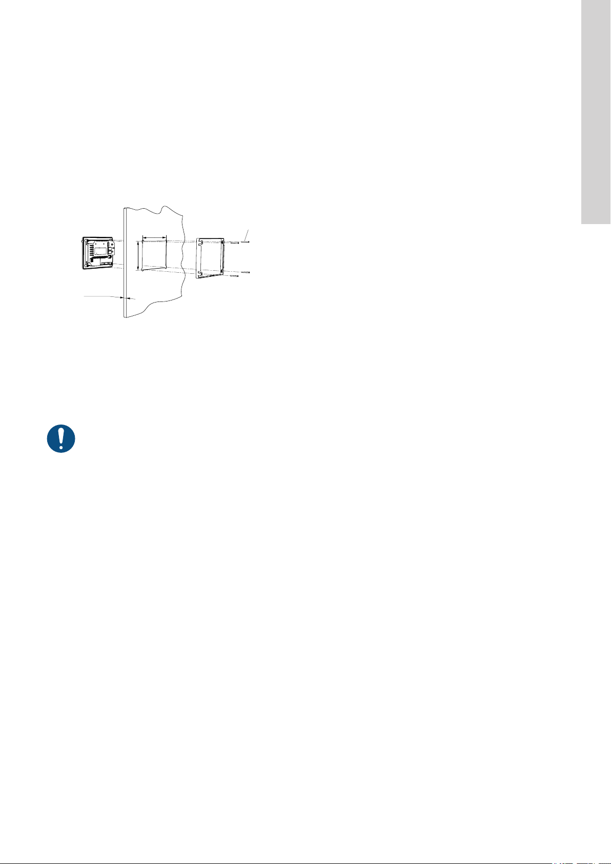
2.2 Mechanical installation
2.2.1 Mounting the control unit
1. Fasten the control unit with the four screws (1), M4 x 12, supplied with the unit. Torque value: 0.5 Nm.
Fig. Mounting the control unit
Related information
8.2 Replacing the control unit
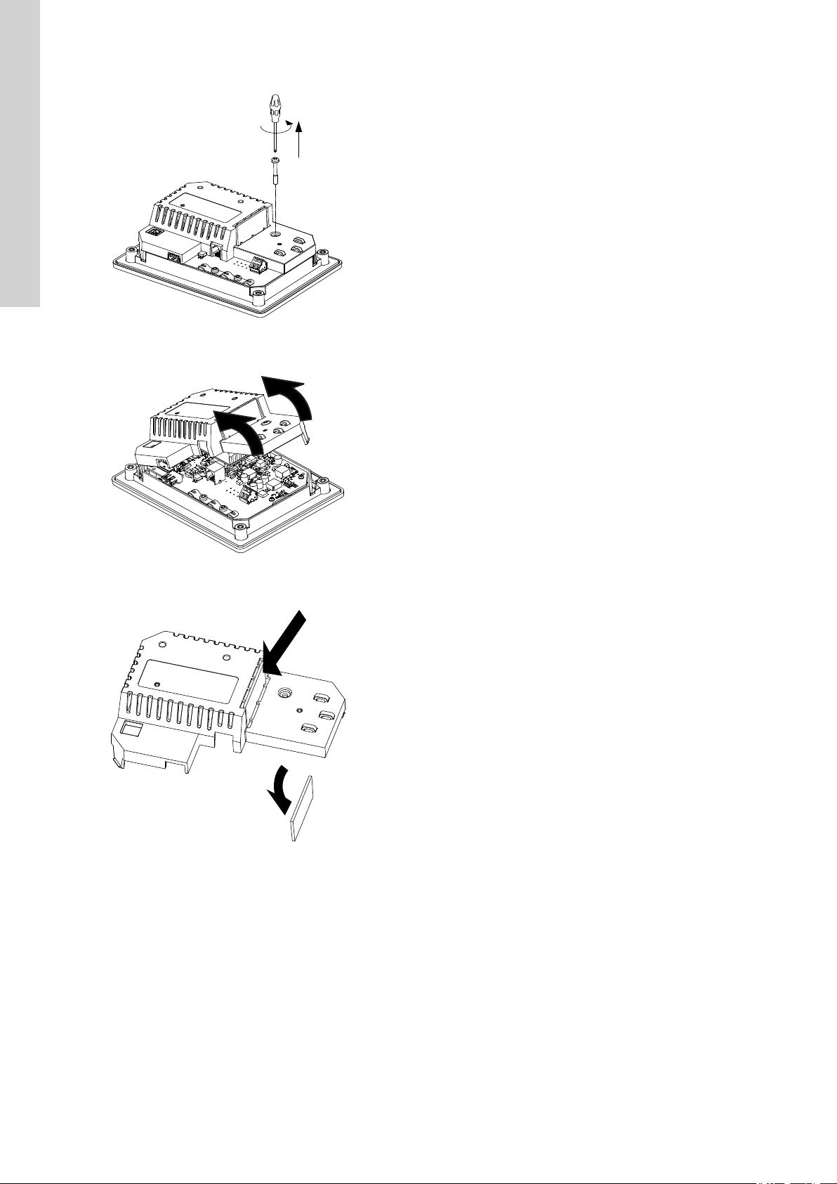
2.2.2 Installing a communication interface module
You can fit a communication interface module (CIM) in the control unit to enable communication with external systems. The module is optional
and is not delivered with the product. See the installation and operating instruction for the module regarding electrical connections.
English (GB)
TM072345
Use an antistatic service kit when handling electronic components. This prevents static electricity from damaging the components.
7
Page 8
English (GB)
1. Remove the screw in the back cover of the CU product.
2. Remove the back cover.
TM071905
3. Break off the tap.
TM071906
TM071977
8
Page 9

4. Fit the CIM module.
English (GB)
TM071907
9
Page 10

Type:
Kit Funct. module - Geni/RS485Op
0538
9854
CIM XXX
CIM XXX
96824795
V01
Prod. No.
Version
Serial No.
P. C.
English (GB)
5. If supplied, place the labels on the back cover.
6. Refit the back cover to the CU product and secure it with the mounting screw. Secure cables using the cable tie holders.
TM071908
10
TM071909
Page 11

2.3 Electrical connection
2.3.1 Connecting the power supply
1. Check that the supply voltage corresponds with the needed 24 VDC and ensure that the polarity is connected correctly according to the
label on the product itself.
2. Connect the power cables and pump cables according to the relevant electrical diagram.
Connecting a wire to a terminal with spring clamps
3. Starting up the product
3.1 Connecting to Grundfos GO Remote
1. Open Grundfos GO Remote on your device. Make sure that Bluetooth is enabled.
Your device must be within reach of the product to establish Bluetooth connection.
2. Press the Bluetooth CONNECT button on Grundfos GO Remote.
3. Press the connect button on the operating panel. The blue LED above the connect button is flashing blue until your device is connected.
Grundfos GO Remote is now loading the data for the product.
Related information
3.4 How to enable Bluetooth on the operating panel
3.5 How to disable Bluetooth on the operating panel
English (GB)
TM070570
3.2 Startup wizard on Grundfos GO Remote
The product is designed for Bluetooth communication with Grundfos GO Remote.
Once you have connected your product to Grundfos GO Remote, a startup wizard appears. Follow the instructions to make your settings.
Grundfos GO Remote enables you to set functions and gives you access to status overviews, technical product information and current
operating parameters.
Related information
8.2 Replacing the control unit
3.3 Startup wizard on the operating panel
The first time the control unit is switched on, a startup wizard will guide you through the basic settings. You can select the sensor type and
sensor levels. For some products, you can also set the nominal pump current and number of phases.
If you have an analog sensor, select S-1 and set the height of the different levels, from dry running to high level.
If you have a digital sensor, select S-2 and enable or disable the dry-running level, the start level for pump 2, if available and the high level.
To change settings, use the Up and Down buttons on the operating panel.
Use the OK button to confirm each setting and navigate to the next setting.
For filling applications, you must use Grundfos GO Remote.
Units can only be changed with Grundfos GO Remote.
Designation
S-1 Analog sensor
S-2 Digital sensor
Related information
6.22 Starting the startup wizard with the operating panel
Description
3.4 How to enable Bluetooth on the operating panel
If the Bluetooth signal on the operating panel has been disabled for some reason, you are not able to connect with Grundfos GO Remote. You
must enable Bluetooth first.
1. Press and hold the connect button on the operating panel for 15 seconds. Wait for the blue LED to light up.
2. Press the Bluetooth CONNECT button on Grundfos GO Remote.
3. Press the connect button on the operating panel. The blue LED above the connect button is flashing blue until your device is connected
Grundfos GO Remote is now loading the data for the product.
11
Page 12

English (GB)
Related information
3.1 Connecting to Grundfos GO Remote
3.5 How to disable Bluetooth on the operating panel
In some installation areas it is not allowed to have a Bluetooth signal enabled during operation. After installation, the Bluetooth signal must be
disabled manually.
1. Press and hold the connect button on the operating panel for 15 seconds. Wait for the blue LED to switch off.
Grundfos GO Remote is not connected to the product anymore.
Related information
3.1 Connecting to Grundfos GO Remote
3.6 Testing the product
When you have made all the electrical installations and completed the startup wizard, you can test the system.
For emptying applications:
• Fill the pit with water and check that the pump starts automatically at the defined level.
• Test the dry-running function by starting the pump manually and wait while the pit with the pump is emptied. Check that the control unit
indicates an alarm and stops the pump when the defined level is reached.
• Test the high-level function by stopping the pump manually and continue to fill the pit with water. Check that the control unit indicates an
alarm when the defined level is reached. Set the pump to Auto and observe that the pump starts and stops when the stop level has been
reached.
For filling applications:
• Start by draining the tank to be filled. When the tank is empty and the start level is reached, the pump must start. When the tank is full and
the stop level is reached, the pump must stop.
• Test the high-level function by stopping the pump manually and continue to fill the tank without the pump with water. Check that the control
unit indicates an alarm when the defined level is reached.
• Test the dry-running function by starting the pump manually and wait while the tank with the pump is emptied. Check that the control unit
indicates an alarm and stops the pump when the defined level is reached. If the pump is placed in a well, this test may not be possible
since the pump cannot empty the well. Alternatively, pull the dry-run level switch up to simulate a dry-run situation. The same can be done
with a pressure level sensor.
4. Product introduction
4.1 Product description
The level-control unit switches the pump on and off according to the liquid level measured by float switches or a pressure sensor. When the
start level is reached, the pump starts, and when the liquid level has been lowered to the stop level, the pump is stopped by the control unit.
An alarm is indicated in case of for example high-water level in the tank or sensor failure.
Basic settings are configured via the operating panel and advanced settings are configured with Grundfos GO Remote. Furthermore, you can
read important operating parameters with Grundfos GO Remote.
4.2 Intended use
The control unit is designed to control two pumps.
The product can be configured for two purposes: emptying a wastewater pit or filling a pit or tank. The product can be used for network
pumping stations, main pumping stations, commercial buildings and municipal systems.
The control unit is only intended for use in control panels.
4.3 Features
The control unit features among others the following functions:
• support of up to two pumps
• manual and automatic control of the pump
• Bluetooth pairing with Grundfos GO Remote
• operating indication, such as power on and pump running
• alarm and warning indication, such as power phase missing and high-water level
• motor and phase failure protection
• setting of stop delays matching the actual operating conditions.
• automatic alternation of pumps.
4.4 Application types
You can choose between two application types:
• Empty
• Fill
You can set the application type with Grundfos GO Remote.
12
Page 13

Empty
1
2
3
4
5
1
2
3
4
5
Pos. Description
1 High level
2 Start level P2: start level for pump 2
3 Start level P1: start level for pump 1
4 Stop level
5 Dry-running level
The pump will start to empty the tank or pit when Start level P1 is reached.
A second pump will start if the liquid level reaches Start level P2.
The pump stops when the liquid level is lowered to Stop level.
If the inflow of liquid exceeds the capacity of the installed pump, the level in the tank or pit will rise. Eventually, the High level sensor will
register a high liquid level in the tank or pit. If set, the signal from the High level sensor can be used to activate an output relay which can then
be used to indicate a visual or acoustic alarm or send a signal to a SCADA system.
If the pump is running and the liquid level in the tank or pit falls below the dry-running level, the dry-running protection will stop the pump to
ensure that it is not damaged mechanically.
Fill
English (GB)
TM0713341
Designation
Description
1 High level
2 Stop level
3 Start level P1: start level for pump 1
4 Start level P2: start level for pump 2
5 Dry-running level
In the filling application, the pump is installed in a tank or well from where it pumps the liquid. The liquid is pumped into a second tank where
the level sensors are installed.
The pump will start to fill the second tank when Start level P1 is reached.
A second pump will start if the liquid level reaches Start level P2.
The pump stops when the liquid level reaches Stop level.
If the pump for some reason does not stop at Stop level and the liquid level keeps rising, the High level sensor will eventually register this. If
set, the signal from the High level sensor can be used to activate a relay output which can then be used to indicate a visual or acoustic alarm
or send a signal to a SCADA system via a communication interface.
If the pump is running and the liquid level in the tank falls below the dry-running level, the dry-running protection will stop the pump to ensure
that it is not damaged.
Related information
7.1.2 Automatic operation
TM0713351
13
Page 14

7
1
4
5
6
3
2
Type
P.N.
UN
Pmax
IP
99350754
S.N.
P.C.
°C
P1
Tamb max
DK - 8850 Bjerringbro Denmark
Made in Denmark
1
2
3
4
567
9
10
11
8
English (GB)
4.5 Terminals
Pos. Description
1 Terminal for a CIM module, optional
2 Cable tie holders
3 Terminal for the power supply
4 GENIbus, for internal use between modules.
5 USB port
6 Service connection
7 Nameplate
4.6 Identification
4.6.1 Nameplate
TM072351
Pos.
Description
1 Production code, year and week
2 Serial number
3 Enclosure class
4 Max. ambient temperature
5 Max. power consumption
6 Factory code
7 Markings and approvals
8 Production site
9 Supply voltage
10 Version number
11 Product name
4.6.2 Type key
Example
CU 241 1
Pos. 1 2
TM072129
Pos.
1
2 Number of pumps supported
14
Description
Type
• CU 241
Page 15

4.7 Supported communication interface modules and protocols
7
6
8
8
9
11
10
13
14
15
12
5
4
3
2
1
ft
m
The following Grundfos communication interface modules can be added to the product.
Communication interface module Protocol
CIM 050 GENIbus
CIM 150 PROFIBUS DP
CIM 200 Modbus RTU
CIM 260 3G/4G
CIM 270 GRM
CIM 280 Grundfos iSolution Cloud (GiC)
Modbus TCP
CIM 500
PROFINET IO
GRM IP
5. Control functions
5.1 Operating panel
English (GB)
TM070082
Pos. Symbol Description
1 Display
2
3 High level
Units
4 Start level, pump 2
5 Start level, pump 1
6 Stop level, pump 1 and 2
7 Dry-running level
8
9
10
Up/Down buttons:
• Press these buttons to navigate between submenus or change the value settings.
OK button:
• Press this button to save changed values.
Connect button:
• Press this button to connect the control unit to Grundfos GO Remote via Bluetooth.
15
Page 16
On
Off
Auto
Setpoint
5.00 bar
Control mode
Const. pressure
Status Settings Assist
1 2 3
English (GB)
Pos. Symbol Description
11
12
13 Display The display shows the pump status.
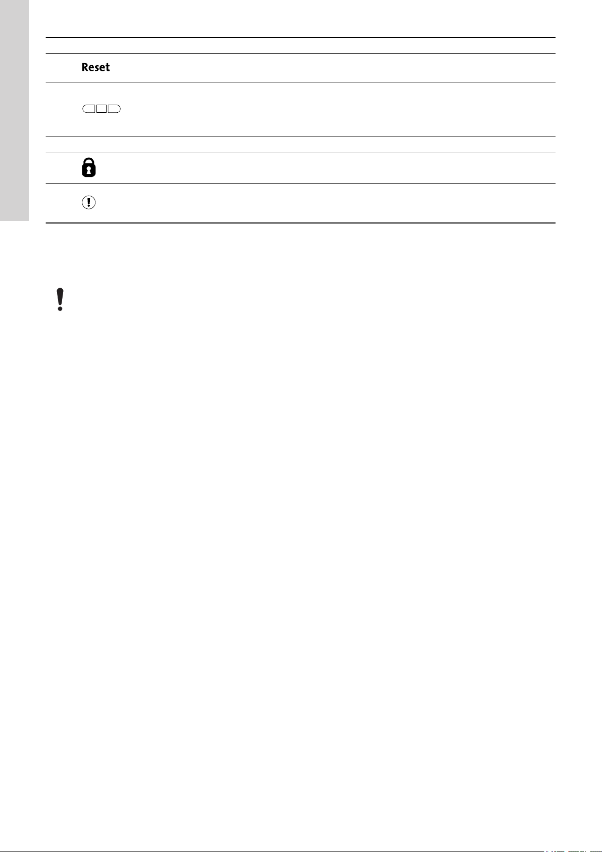
Reset button:
• Press this button during startup to reset settings and start over or to reset an alarm or warning.
Operating mode for the pump:
• On: The pump has been switched on manually.
• Off: The pump has been switched off manually.
• Auto: The pump is running automatically based on settings.
14
15
The control unit enables manual setting and monitoring of the system.
Lock symbol:
If the symbol is lit, the control unit is locked from making changes.
Alarm and warning symbol:
Red: Alarm
Yellow: Warning
6. Setting the product
Make sure that all settings are entered according to the pump and system requirements to avoid malfunction.
6.1 Setting the application type with Grundfos GO Remote
1. Go to Settings > Level control > Application type.
2. Select the type.
• Empty
• Fill
6.2 Setting the sensor type
6.2.1 Setting the sensor type with Grundfos GO Remote
1. Go to Settings > Level control > Sensor type.
2. Select the type.
• Analog sensors
• Digital sensors
6.2.2 Setting the sensor type with the operating panel
1. Press and hold OK until S-1 or S-2 starts flashing.
2. Select the sensor type using the Up and Down buttons.
• S-1: Analog sensors
• S-2: Digital sensors.
3. Press OK to confirm the setting.
4. Continuously press OK to confirm all other settings and to exit the setup.
6.3 Setting the start level
6.3.1 Setting the start level with Grundfos GO Remote
The settings apply to analog sensors. For digital sensors, the setting is automatically activated.
1. Go to Settings > Level Control > Start level P1.
2. Set the start level for pump 1.
3. Go to Settings > Level Control > Start level P2.
4. Set the start level for pump 2.
6.3.2 Setting the start level with the operating panel
The settings apply to analog sensors. For digital sensors, the setting is automatically activated.
16
Page 17

1. Press and hold OK until the display and dry running start flashing.
2. Continuously press OK until the indicator light for the start level for pump 1 starts flashing.
3. Set the start level for pump 1 by using the Up and Down buttons.
4. Press OK.
The indicator light for the start level for pump 2 starts flashing.
English (GB)
TM071336
5. Set the start level for pump 2 by using the Up and Down buttons.
6. Continuously press OK until the display stops flashing.
The settings have now been stored.
6.4 Setting the stop level
6.4.1 Setting the stop level with Grundfos GO Remote
The settings apply to analog sensors. For digital sensors, the setting is automatically activated.
The stop level is the same for pump 1 and pump 2.
1. Go to Settings > Level control > Stop level
2. Set the stop level.
If you are using the same level for start and stop, remember to set a stop delay. This will prevent the pump from starting and
stopping too frequently.
6.4.2 Setting the stop level with the operating panel
The settings apply to analog sensors. For digital sensors, the setting is automatically activated.
The stop level is the same for pump 1 and pump 2.
1. Press and hold OK until the display starts flashing.
2. Press OK once.
The current stop level is indicated on the display.
3. Set the stop level using the Up and Down buttons.
4. Continuously press OK to confirm all other settings and to exit the setup.
TM071337
If you are using the same level for the start and stop level, remember to set a stop delay. This will prevent the pump from starting
and stopping too frequently.
6.5 Setting the high level
6.5.1 Setting the high level with Grundfos GO Remote
For analog sensors:
17
Page 18

English (GB)
1. Go to Settings > Level control > High level.
2. Set the high level.
For digital sensors:
1. Go to Settings > LC 231 IO terminals
2. Select which terminal to configure.
6.5.2 Setting the high level with the operating panel
The settings apply to analog sensors
1. Press and hold OK until the display starts flashing.
2. Press OK four times. The current high level is indicated on the display.
3. Set the high level using the Up and Down button.
For digital sensors, enable or disable the setting.
1. Press OK once to complete the setting.
6.6 Stop delay
The stop delay is the time from when the stop level is reached until the pump stops. The stop delay prevents the pump from starting and
stopping too frequently and reduces water hammer in long pipes.
6.6.1 Setting the stop delay with Grundfos GO Remote
1. Select Settings > Level control > Stop delay > State
2. Select Stop delay time.
3. Set the Stop delay time.
6.7 Power-on delay
With this function it is possible to delay the startup of the pump after the power supply has been switched on. The purpose is to avoid
disturbing the main power network which could happen if several pumps start up immediately when the power supply is switched on.
6.7.1 Setting the power-on delay with Grundfos GO Remote
1. Go to Settings > Power-on delay.
2. Set the function to Enabled.
3. Set the time delay.
6.8 Dry-running protection
If the pump is running and the liquid level in the tank or pit becomes lower than the dry-running level, the dry-running protection will stop the
pump to ensure that it is not damaged.
Dry-running protection is dependent on a feedback signal from a level sensor installed in the tank or pit.
6.8.1 Setting the dry-running level with Grundfos GO Remote
1. Go to Settings > Level control > Dry-running level.
2. Set the dry-running level.
The dry-running level must be set to a value which ensures that the pump is not damaged due to dry-running. The specific level
depends on the installed pump type. See the installation and operating instructions for the product.
6.8.2 Setting the dry-running level with the operating panel
1. Press and hold OK until the display starts flashing.
2. Set the dry-running level using the Up or Down button.
3. Continuously press OK to confirm all other settings and to exit the setup.
6.9 "Multipump settings"
The control unit enables start and stop of the two pumps alternately. The pump with the lowest number of running hours is always started first.
The function ensures that the running hours of the pumps are the same.
It is possible to set a time delay before the next pump is started.
6.9.1 Setting "multipump settings" with Grundfos GO Remote
1. Go to Settings > Multi pump settings
2. Set Inter pump delay.
This is the starting delay between the pumps ensuring that they do not start at the same time.
3. Set Max number of running pumps.
This is the maximum number of pumps which are allowed to run at the same time.
6.10 Using the same level switch for the start and stop level
1. Set one digital input to Start pump 1 or Stop. All other digital inputs must be disabled.
2. Set a stop delay.
This will prevent the pump from starting and stopping too frequently.
18
Page 19

6.11 "Antiseizing"
The Antiseizing function prevents a pump from choking or seizing up as a result of deposits buildup. Antiseizing is used in pits that have had
no inlet flow for a long period. The Antiseizing function ensures that the pump starts as often as set in Antiseizing > interval. The pump will
operate for the number of seconds indicated by the user.
6.11.1 Setting the "Anti-seizing" function with Grundfos GO Remote
1. Go to Settings > Anti-seizing.
2. Set the function to Enabled.
3. Set the time interval.
4. Set the operating time.
6.12 Signal-detection time
The signal-detection time is the minimum time a level has to be active before the control unit initiates an action, such as starting or stopping a
pump.
6.12.1 Setting the signal-detection time with Grundfos GO Remote
1. Go to Settings > Level control > Signal detection time.
2. Set the signal-detection time.
6.13 Setting the maximum number of restarts with Grundfos GO Remote
If the pump is seized up as a result of deposits buildup, it will be stopped automatically due to overheating, provided that the motor protection
has been set. When the motor has cooled down, the control unit will unsuccessfully try to restart the pump and this scenario will be repeated.
In order to prevent this, it is possible to set a maximum number of restart attempts within a set interval.
1. Go to Settings > Max number of restarts.
2. Enable the function.
3. Set the interval within which the allowed number of restarts are to be counted.
4. Set the maximum number of pump restarts which are allowed during the set interval.
Related information
6.15.4 Setting the motor protection with Grundfos GO Remote
9.3 Code 4 (Too many motor restarts)
English (GB)
6.14 Setting the service interval with Grundfos GO Remote
You can set a time in Grundfos GO Remote in order to get a reminder that the pump needs service when the time comes.
1. Go to Settings > Service > State
2. Select Enable and press OK.
3. Select the pump.
4. Enter the number of hours until next service and press OK.
6.15 Motor protection
6.15.1 Overheat protection
The control unit offers thermal protection for the connected motors. Two types of thermal-protection sensor can be connected to the control
unit: a PTC sensor (analog) and a thermal switch (digital).
Under normal running conditions, the sensor will act as a short circuit, but when its temperature limit is reached, it will open and tell the control
unit that the temperature is too high, and the pump is stopped. When the temperature has dropped to the sensor-trigger level, the pump will
return to normal running conditions. It will not be possible to start the pump manually as long as the temperature is too high.
Related information
9.10 Code 69 (Winding temperature too high)
6.15.2 Overload protection
The pump is protected by a motor-protection relay. The nominal current draw must be set manually on the motor-protection relay. See the
specific documentation for the relay on how to set the trigger level. If the current exceeds the trigger level, the relay will switch off the pump
and the controller will give an alarm. The alarm has to be manually reset directly on the motor protection relay.
Related information
9.8 Code 48 (Motor is overloaded)
6.15.3 Moisture protection
When a moisture sensor is installed in series with the temperature sensor, the control unit needs to know how to determine whether there is a
high temperature or moisture in the pump. If the temperature is too high, normally the temperature sensor will go back to its normal stage
when the temperature has dropped to its trigger level. If there is moisture in the pump, then the moisture sensor will keep the series
connection open until the pump is opened and serviced.
To determine which sensor has been active, a cool down time must be entered. This is the time that will normally pass until the temperature
has dropped enough for the temperature sensor to return to its normal stage. If the cool down time is exceeded, the control unit will assume
that there is moisture in the pump, and it will send a moisture alarm.
19
Page 20

English (GB)
Related information
6.15.4 Setting the motor protection with Grundfos GO Remote
6.15.4 Setting the motor protection with Grundfos GO Remote
You can set the current, temperature and moisture protection via a setup wizard.
1. Go to Settings > Motor protection pump 1 or Motor protection pump 2.
2. Follow the on-screen wizard to set the following:
• Nominal pump current
• Trip IEC class
• Pump connection
• Overheat protection.
Related information
6.13 Setting the maximum number of restarts with Grundfos GO Remote
6.15.3 Moisture protection
6.16 Alarm reset
6.16.1 Resetting alarms and warnings manually with Grundfos GO Remote
1. Go to Alarms and warnings.
2. Press Reset alarm.
All current alarms and warnings have been reset. However, if the fault causing the alarm or warning has not been removed, the alarm or
warning will appear again.
3. If you want to delete all alarms and warnings from the history log, press Show log > Reset alarm and warning logs.
6.16.2 Setting the automatic alarm reset with Grundfos GO Remote
1. Go to Settings > Automatic alarm reset.
2. Select one of the following:
No automatic reset
All except pump critical
All alarms
6.16.3 Resetting alarms and warnings on the operating panel
You can manually reset alarms and warnings on the operating panel. However, if the fault causing the alarm or warning has not been removed,
the alarm or warning will appear again.
1. Press Reset on the operating panel to reset the alarm or warning.
The control unit does not reset any alarm or warning. You must do
it manually.
The control unit resets alarms and warnings unless the related fault
can damage the pump.
The control unit resets alarms and warnings, regardless of the
fault.
6.17 Setting the buzzer with Grundfos GO Remote
The internal buzzer is used to give an acoustic sound if there is a warning or an alarm.
1. Go to Settings > Buzzer settings.
2. Select when the buzzer is to be activated:
• All alarms
• All alarms and warnings.
6.18 Setting units for Grundfos GO Remote
Changing units as described here will only change the units shown in Grundfos GO Remote. It will not affect the units shown on the operating
panel of products connected to Grundfos GO Remote.
20
Page 21
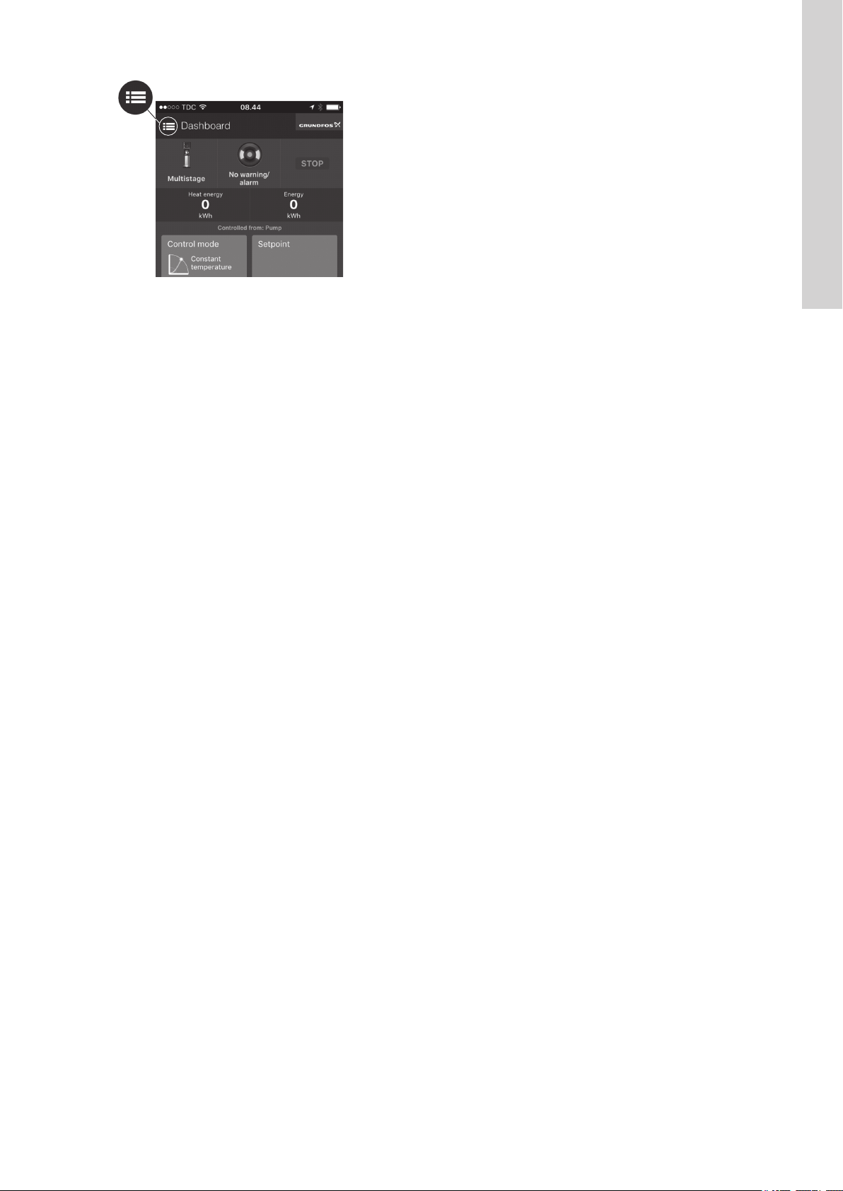
1. Press the Menu button in the upper left corner of Grundfos GO Remote.
2. Go to General > Settings > Products > Units.
3. Select US or Grundfos default units.
6.19 Setting units for the operating panel with Grundfos GO Remote
Changing units as described below changes the units shown in the operating panel of the product connected to Grundfos GO Remote. It does
not affect the units shown in Grundfos GO Remote.
1. Go to Settings > Display units.
2. Select the units to be used on the operating panel.
• SI Units
• US Units.
English (GB)
TM070084
6.20 GENIbus
GENIbus, the Grundfos Electronics Network Intercommunications bus, is a fieldbus developed by Grundfos to meet the need for data transfer
in all typical Grundfos motor or pump applications. Grundfos devices with GENIbus can be wired together in networks and integrated in
automation systems. Each device on the network must have a unique GENIbus address. GENIbus is based on the RS485 hardware standard
and typically operates at a baud rate of 9600 bits/s.
6.20.1 Setting the GENIbus address with Grundfos GO Remote
If CU 241 is used in a GENIbus network, a CIM 050 must be installed to add a GENIbus connection.
1. Go to Settings > GENI bus address.
2. Set the GENIbus address.
The GENIbus address is a unique identifier for the product on the network.
6.21 Security
6.21.1 Locking the operating panel
The operating panel can only be locked with Grundfos GO Remote.
1. Go to Settings > Security > Lock display.
2. Enable the setting and press Done.
3. Select if you want to restrict access to Settings only or Settings and operation.
4. Press Done.
The lock symbol on the operating panel is now lit.
6.21.2 Unlocking the operating panel
The operating panel can only be unlocked with Grundfos GO Remote.
1. Go to Settings > Security > Lock display.
2. Disable the setting and press Done.
The lock symbol on the operating panel is switched off.
6.21.3 Locking Grundfos GO Remote
1. Go to Settings > Security > Lock GO Remote.
2. Enable the setting and press Done.
3. Enter a four digit PIN code and press CONFIRM.
A lock symbol indicates which menus are locked. To view or change settings, you must enter the PIN code.
6.21.4 Unlocking Grundfos GO Remote
1. Go to Settings > Security.
2. Enter the four digit PIN code.
21
Page 22

English (GB)
3. Select Lock GO Remote.
4. Disable the setting and press Done.
All menus in Grundfos GO Remote are unlocked.
6.22 Starting the startup wizard with the operating panel
• Press and hold the OK button for 8 seconds until S-1 or S-2 starts flashing.
Related information
3.3 Startup wizard on the operating panel
7. Operating the product
7.1 Manual operation
7.1.1 Starting and stopping the pump manually with Grundfos GO Remote
1. Go to Settings > Control, pump 1 or Control, pump 2.
2. Start the pump by selecting On and pressing OK.
3. Stop the pump by selecting Off and pressing OK.
Related information
7.1.4 Choosing what the pump must do after manual start
7.1.2 Automatic operation
In automatic operating mode, the control unit starts and stops the pump based on the signals it receives from the connected level sensors and
the corresponding level settings within the control unit.
Related information
4.4 Application types
7.1.3 Starting and stopping the pump manually with the operating panel
1. To start a pump manually, press and hold the Pump button until the pump starts.
The On indicator light is lit when the pump is operating in manual mode.
2. Stop the pump by pressing the Pump button.
The Off indicator light is lit when the pump is stopped.
Related information
7.1.4 Choosing what the pump must do after manual start
7.1.4 Choosing what the pump must do after manual start
The following can be configured:
• Automatic return
Here you select if the pump must automatically return to a defined operating mode when the manual start ends.
• Return to
Here you select whether the pump must return to automatic operating mode or stop when the manual start ends and Automatic return
has been enabled.
• Forced start time
Here you set the time period in which the pump must run in manual operating mode.
1. Go to Settings > Manual start.
2. Select Automatic return and choose one of the following options:
• Disabled
• Enabled.
3. Go one step back in the menu and select Return to.
4. Choose one of the following options:
• Auto
• Off.
5. Go one step back in the menu and select Forced start time.
6. Set the time period in which the pump must run in manual operating mode.
Related information
7.1.1 Starting and stopping the pump manually with Grundfos GO Remote
7.1.3 Starting and stopping the pump manually with the operating panel
22
Page 23
8. Servicing the product
WARNING
Electric shock
Death or serious personal injury
‐ Switch off the incoming power supply before you start any work on the product or connected pumps.
‐ Make sure that the power supply cannot be switched on accidentally.
8.1 Updating the product software
New features and functions can be made available during the product's life cycle.
1. Contact Grundfos to get your product software updated.
8.2 Replacing the control unit
WARNING
Electric shock
Death or serious personal injury
‐ Switch off the power supply before making any electrical connections.
‐ Make sure that the power supply cannot be switched on accidentally.
Remember to save the controller's settings in Grundfos GO Remote under Settings. The settings can then be transferred to the new control
unit when installed.
1. Switch off the power supply to the product and other components with external supply.
2. Write down the terminal connection of each wire to ensure correct re-connection.
3. Disconnect all wires.
4. Remove the control unit from the panel or cabinet.
5. Fit the new unit.
6. Connect all wires.
7. Configure the new control unit using Grundfos GO Remote.
Related information
2.2.1 Mounting the control unit
3.2 Startup wizard on Grundfos GO Remote
English (GB)
8.3 Replacing the CIM module
WARNING
Electric shock
Death or serious personal injury
‐ Switch off the power supply before making any electrical connections.
‐ Make sure that the power supply cannot be switched on accidentally.
1. Switch off the power supply to the product and other components with external supply.
2. Write down the terminal connection of each wire to ensure correct re-connection.
3. Disconnect all wires connected to the CIM module.
4. Remove the screws that holds the module.
5. Remove the module from the control unit.
6. Fit the new module.
7. Connect all wires.
8.4 Replacing the battery
CAUTION
Fire and chemical leakage
Minor or moderate personal injury
‐ Risk of explosion if the battery is replaced by an incorrect type.
To replace the battery, do the following:
1. Remove the back cover.
2. Gently grab around the battery without touching it too much.
3. Pull the battery up.
4. Insert a new battery of the correct type.
Related information
10. Technical data
23
Page 24
English (GB)
9. Fault finding the product
Fault finding and fault correction must be carried out by qualified persons.
9.1 Overview of alarm and warning codes
Code number Description
Code 2 The power phase is missing.
Code 4 Too many motor restarts.
Code 9 The power-phase sequence is wrong.
Code 12 Service is needed.
Code 22 Moisture in motor of pump.
Code 25 Wrong configuration.
Code 48 The motor is overloaded.
Code 57 Missing water in the application.
Code 69 The winding temperature is too high.
Code 84 The memory-storage media is faulty.
Code 117 The door is opened.
Code 159 Communication error CIMxxx.
Code 165 Signal fault.
Code 191 High water level.
Code 205 Level-switch inconsistency.
Code 225 Communication error pump module.
Code 226 Communication error IO module.
Code 229 Water on the floor.
WARNING
Electric shock
Death or serious personal injury
‐ Switch off the power supply before you start any work on the product.
‐ Make sure that the power supply cannot be switched on accidentally.
9.2 Code 2 (Power phase missing)
• Alarm code 2 is shown on the display.
• The alarm symbol on the display turns red and the pump stops.
• Alarm code Power phase missing is displayed in Grundfos GO Remote.
Cause
Remedy • Connect the phase.
Cause The fuse is blown somewhere on the incoming power line.
Remedy • Replace the fuse.
One of the power supply phases is not connected.
9.3 Code 4 (Too many motor restarts)
• Alarm code 4 is shown on the display.
• The alarm symbol on the display turns red and the pump stops.
• Alarm code Too many motor restarts is displayed in Grundfos GO Remote.
Cause
Remedy • Remove the blockage from the pump.
Related information
6.13 Setting the maximum number of restarts with Grundfos GO Remote
The pump has been blocked or partly blocked causing overload in the motor.
9.4 Code 9 (Power phase sequence wrong)
• Alarm code 9 is shown on the display.
• The alarm symbol on the display turns red and the pump stops.
• Alarm code Power phase sequence wrong is displayed in Grundfos GO Remote.
Cause
The power supply phase is set incorrectly.
24
Page 25

Remedy • Interchange two phases.
9.5 Code 12 (Service needed)
• Warning code 12 is shown on the display if you press the Up or Down button.
• The warning symbol on the display turns yellow and the pump's operating mode is unchanged.
• Warning code Service needed is displayed in Grundfos GO Remote.
Cause The pump requires service based on time to next service countdown.
Remedy • Contact Grundfos or an authorised service workshop.
• In order for the product to determine the service time, you must have enabled the service countdown with Grundfos GO
Remote: Settings > Service
9.6 Code 22 (Moisture in motor of pump)
• Alarm code 22 is shown on the display.
• The alarm symbol on the display turns red and the pump stops.
• Alarm code Moisture in motor of pump is displayed in Grundfos GO Remote.
Cause Moisture is detected in the motor of the pump.
Remedy • Service is needed on the pump. Contact Grundfos.
9.7 Code 25 (Wrong configuration)
• Alarm code 25 is shown on the display.
• The alarm symbol on the display turns red and the pump stops.
• Alarm code Wrong configuration is displayed in Grundfos GO Remote.
Cause
Remedy • Check and adjust the level control configuration with Grundfos GO Remote.
The level control is not configured correctly.
English (GB)
Cause The IO terminal is not configured correctly.
Remedy • Select which IO terminal to change in Grundfos GO Remote and adjust the configuration.
9.8 Code 48 (Motor is overloaded)
• Alarm code 48 is shown on the display.
• The alarm symbol on the display turns red and the pump stops.
• Alarm code Motor is overloaded is displayed in Grundfos GO Remote.
Cause
Remedy • Remove the blockage.
Related information
6.15.2 Overload protection
The pump is clogged.
The blockage causes the motor current to rise, which could damage the pump.
• Check the pit conditions to ensure blockage is not possible again.
9.9 Code 57 (Missing water in the application)
• Alarm code 57 is shown on the display.
• The alarm symbol on the display turns red and the pump stops.
• Alarm code Dry Run is displayed in Grundfos GO Remote.
Cause
Remedy • Check and configure the sensor for stop level.
Low water level in the pit and the pump stops due to the dry-running function.
9.10 Code 69 (Winding temperature too high)
• Alarm code 69 is shown on the display.
• The alarm symbol on the display turns red and the pump stops.
• Alarm code Winding temperature too high is displayed in Grundfos GO Remote.
Cause
Remedy • Remove the blockage.
Cause The pump has run for too long.
Remedy • Allow the pump to cool down.
The pump is clogged, causing the pump to use more current and thereby overheat.
• Adjust the distance between start and stop levels.
25
Page 26

English (GB)
Related information
6.15.1 Overheat protection
9.11 Code 84 (Memory storage media faulty)
• Warning code 84 is shown on the display if you press the Up or Down button.
• The warning symbol on the display turns yellow and the pump's operating mode is unchanged.
• Warning code Memory storage media faulty is displayed in Grundfos GO Remote.
Cause An error in the internal memory has been detected.
Remedy • Replace the control unit.
9.12 Code 117 (Door opened)
• Warning code 117 is shown on the display if you press the Up or Down button.
• The warning symbol on the display turns yellow and the pump's operating mode is unchanged.
• Warning code Door opened is displayed in Grundfos GO Remote.
Cause The door to the control-unit room has been opened.
Remedy • Check the room with the control unit.
9.13 Code 159 (Communication error CIMxxx)
• Warning code 159 is shown on the display if you press the Up or Down button.
• The warning symbol on the display turns yellow and the pump's operating mode is unchanged.
• Warning code Communication error CIMxxx is displayed in Grundfos GO Remote.
• The CIM module is unable to communicate with the product.
Cause
Remedy • Ensure that the module, including cables, is fitted correctly.
• Contact Grundfos or an authorised service workshop.
The CIM module is installed incorrectly.
Cause The CIM module is defective.
Remedy • Contact Grundfos.
9.14 Code 165 (Signal fault)
• Alarm code 165 is shown on the display.
• The alarm symbol on the display turns red and the pump stops.
• Alarm code Signal fault is displayed in Grundfos GO Remote.
Cause
Remedy • Go to Settings > Level Control in Grundfos GO Remote and ensure that the configured range corresponds to the
The signal from the sensor is out of the configured range.
physical application type.
• Change the sensor, if needed.
9.15 Code 191 (High water level)
• Alarm code 191 is shown on the display.
• The alarm symbol on the display turns red, but the pump's operating mode is unchanged.
• Alarm code High water level is displayed in Grundfos GO Remote.
Cause
Remedy • Check and configure the sensor for start level.
Cause The pump is not big enough to remove the water.
Remedy • Contact Grundfos or an authorised service workshop.
The defined start level did not start the pump.
Cause The level sensor is defective and not reacting on level changes.
Remedy • Check the functionality of the level sensor.
9.16 Code 205 (Level switch inconsistency)
• Alarm code 205 is shown on the display.
• The alarm symbol on the display turns red and the pump stops.
• Alarm code Level switch inconsistency is displayed in Grundfos GO Remote.
Cause
Remedy • Check the functionality of each float switch.
A float switch could be defective or stuck.
26
Page 27

9.17 Code 225 (Communication error pump module)
187 (7.36")
137 (5.4")
52 (2")
• Alarm code 225 is shown on the display.
• The alarm symbol on the display turns red and the pump stops.
• Alarm code Communication error is displayed in Grundfos GO Remote.
• The pump module is unable to communicate with the product.
Cause The connection to GENIbus is missing.
Remedy • Check the GENIbus connection cable between CU 241 and IO 242.
Cause The pump module is defective.
Remedy • Contact Grundfos.
9.18 Code 226 (Communication error IO module)
• Alarm code 226 is shown on the display.
• The alarm symbol on the display turns red and the pump stops.
• Alarm code Communication error is displayed in Grundfos GO Remote.
• The pump module is unable to communicate with the product.
Cause The connection to GENIbus is missing.
Remedy • Check the GENIbus connection cable between CU 241 and IO 242.
Cause The IO module is defective.
Remedy • Contact Grundfos.
English (GB)
9.19 Code 229 (Water on floor)
• Warning code 229 is shown on the display if you press the Up or Down button.
• The warning symbol on the display turns yellow and the pump's operating mode is unchanged.
• Warning code Water on floor is displayed in Grundfos GO Remote.
Cause
The sensor detects water on the floor.
Remedy • Check for water leakage.
10. Technical data
Supply voltage
24 VDC, - 10 %/+ 10 %.
Power supply is required to be class 2.
Check that the supply voltage corresponds to the values stated on the nameplate.
Maximum power dissipation
Object
99347488 3.4 W
Enclosure class
IP54, 3R for CU 241 built into panel of similar or higher enclosure class.
GENIbus terminal
- 7 VDC to + 12 VDC.
Nominal current condition: 4 mADC.
Short-circuit current condition: 328 mA.
Dimensions
Maximum power dissipation
TM072339
Related information
8.4 Replacing the battery
27
Page 28

English (GB)
11. Disposing of the product
This product or parts of it must be disposed of in an environmentally sound way.
1. Use the public or private waste collection service.
2. If this is not possible, contact the nearest Grundfos company or service workshop.
3. Dispose of the waste battery through the national collective schemes. If in doubt, contact your local Grundfos company.
See also end-of-life information at www.grundfos.com/product-recycling.
28
Page 29

Argentina
Bombas GRUNDFOS de Argentina S.A.
Ruta Panamericana km. 37.500 Centro
Industrial Garin
1619 - Garín Pcia. de B.A.
Tel.: +54-3327 414 444
Fax: +54-3327 45 3190
Australia
GRUNDFOS Pumps Pty. Ltd.
P.O. Box 2040
Regency Park
South Australia 5942
Tel.: +61-8-8461-4611
Fax: +61-8-8340-0155
Austria
GRUNDFOS Pumpen Vertrieb Ges.m.b.H.
Grundfosstraße 2
A-5082 Grödig/Salzburg
Tel.: +43-6246-883-0
Fax: +43-6246-883-30
Belgium
N.V. GRUNDFOS Bellux S.A.
Boomsesteenweg 81-83
B-2630 Aartselaar
Tel.: +32-3-870 7300
Fax: +32-3-870 7301
Belarus
Представительство ГРУНДФОС в Минске
220125, Минск
ул. Шафарнянская, 11, оф. 56, БЦ «Порт»
Тел.: +7 (375 17) 286 39 72/73
Факс: +7 (375 17) 286 39 71
E-mail: minsk@grundfos.com
Bosnia and Herzegovina
GRUNDFOS Sarajevo
Zmaja od Bosne 7-7A
BiH-71000 Sarajevo
Tel.: +387 33 592 480
Fax: +387 33 590 465
www.ba.grundfos.com
E-mail: grundfos@bih.net.ba
Brazil
BOMBAS GRUNDFOS DO BRASIL
Av. Humberto de Alencar Castelo Branco,
630
CEP 09850 - 300
São Bernardo do Campo - SP
Tel.: +55-11 4393 5533
Fax: +55-11 4343 5015
Bulgaria
Grundfos Bulgaria EOOD
Slatina District
Iztochna Tangenta street no. 100
BG - 1592 Sofia
Tel.: +359 2 49 22 200
Fax: +359 2 49 22 201
E-mail: bulgaria@grundfos.bg
Canada
GRUNDFOS Canada Inc.
2941 Brighton Road
Oakville, Ontario
L6H 6C9
Tel.: +1-905 829 9533
Fax: +1-905 829 9512
China
GRUNDFOS Pumps (Shanghai) Co. Ltd.
10F The Hub, No. 33 Suhong Road
Minhang District
Shanghai 201106 PRC
Tel.: +86 21 612 252 22
Fax: +86 21 612 253 33
Columbia
GRUNDFOS Colombia S.A.S.
Km 1.5 vía Siberia-Cota Conj. Potrero
Chico,
Parque Empresarial Arcos de Cota Bod. 1A.
Cota, Cundinamarca
Tel.: +57(1)-2913444
Fax: +57(1)-8764586
Croatia
GRUNDFOS CROATIA d.o.o.
Buzinski prilaz 38, Buzin
HR-10010 Zagreb
Tel.: +385 1 6595 400
Fax: +385 1 6595 499
www.hr.grundfos.com
Czech Republic
GRUNDFOS Sales Czechia and Slovakia
s.r.o.
Čajkovského 21
779 00 Olomouc
Tel.: +420-585-716 111
Denmark
GRUNDFOS DK A/S
Martin Bachs Vej 3
DK-8850 Bjerringbro
Tel.: +45-87 50 50 50
Fax: +45-87 50 51 51
E-mail: info_GDK@grundfos.com
www.grundfos.com/DK
Estonia
GRUNDFOS Pumps Eesti OÜ
Peterburi tee 92G
11415 Tallinn
Tel.: + 372 606 1690
Fax: + 372 606 1691
Finland
OY GRUNDFOS Pumput AB
Trukkikuja 1
FI-01360 Vantaa
Tel.: +358-(0) 207 889 500
France
Pompes GRUNDFOS Distribution S.A.
Parc d’Activités de Chesnes
57, rue de Malacombe
F-38290 St. Quentin Fallavier (Lyon)
Tel.: +33-4 74 82 15 15
Fax: +33-4 74 94 10 51
Germany
GRUNDFOS GMBH
Schlüterstr. 33
40699 Erkrath
Tel.: +49-(0) 211 929 69-0
Fax: +49-(0) 211 929 69-3799
E-mail: infoservice@grundfos.de
Service in Deutschland:
kundendienst@grundfos.de
Greece
GRUNDFOS Hellas A.E.B.E.
20th km. Athinon-Markopoulou Av.
P.O. Box 71
GR-19002 Peania
Tel.: +0030-210-66 83 400
Fax: +0030-210-66 46 273
Hong Kong
GRUNDFOS Pumps (Hong Kong) Ltd.
Unit 1, Ground floor, Siu Wai Industrial
Centre
29-33 Wing Hong Street & 68 King Lam
Street, Cheung Sha Wan
Kowloon
Tel.: +852-27861706 / 27861741
Fax: +852-27858664
Hungary
GRUNDFOS Hungária Kft.
Tópark u. 8
H-2045 Törökbálint
Tel.: +36-23 511 110
Fax: +36-23 511 111
India
GRUNDFOS Pumps India Private Limited
118 Old Mahabalipuram Road
Thoraipakkam
Chennai 600 097
Tel.: +91-44 2496 6800
Indonesia
PT GRUNDFOS Pompa
Graha Intirub Lt. 2 & 3
Jln. Cililitan Besar No.454. Makasar,
Jakarta Timur
ID-Jakarta 13650
Tel.: +62 21-469-51900
Fax: +62 21-460 6910 / 460 6901
Ireland
GRUNDFOS (Ireland) Ltd.
Unit A, Merrywell Business Park
Ballymount Road Lower
Dublin 12
Tel.: +353-1-4089 800
Fax: +353-1-4089 830
Italy
GRUNDFOS Pompe Italia S.r.l.
Via Gran Sasso 4
I-20060 Truccazzano (Milano)
Tel.: +39-02-95838112
Fax: +39-02-95309290 / 95838461
Japan
GRUNDFOS Pumps K.K.
1-2-3, Shin-Miyakoda, Kita-ku
Hamamatsu
431-2103 Japan
Tel.: +81 53 428 4760
Fax: +81 53 428 5005
Korea
GRUNDFOS Pumps Korea Ltd.
6th Floor, Aju Building 679-5
Yeoksam-dong, Kangnam-ku, 135-916
Seoul, Korea
Tel.: +82-2-5317 600
Fax: +82-2-5633 725
Latvia
SIA GRUNDFOS Pumps Latvia
Deglava biznesa centrs
Augusta Deglava ielā 60
LV-1035, Rīga,
Tel.: + 371 714 9640, 7 149 641
Fax: + 371 914 9646
Lithuania
GRUNDFOS Pumps UAB
Smolensko g. 6
LT-03201 Vilnius
Tel.: + 370 52 395 430
Fax: + 370 52 395 431
Malaysia
GRUNDFOS Pumps Sdn. Bhd.
7 Jalan Peguam U1/25
Glenmarie Industrial Park
40150 Shah Alam, Selangor
Tel.: +60-3-5569 2922
Fax: +60-3-5569 2866
Mexico
Bombas GRUNDFOS de México
S.A. de C.V.
Boulevard TLC No. 15
Parque Industrial Stiva Aeropuerto
Apodaca, N.L. 66600
Tel.: +52-81-8144 4000
Fax: +52-81-8144 4010
Netherlands
GRUNDFOS Netherlands
Veluwezoom 35
1326 AE Almere
Postbus 22015
1302 CA ALMERE
Tel.: +31-88-478 6336
Fax: +31-88-478 6332
E-mail: info_gnl@grundfos.com
New Zealand
GRUNDFOS Pumps NZ Ltd.
17 Beatrice Tinsley Crescent
North Harbour Industrial Estate
Albany, Auckland
Tel.: +64-9-415 3240
Fax: +64-9-415 3250
Norway
GRUNDFOS Pumper A/S
Strømsveien 344
Postboks 235, Leirdal
N-1011 Oslo
Tel.: +47-22 90 47 00
Fax: +47-22 32 21 50
Poland
GRUNDFOS Pompy Sp. z o.o.
ul. Klonowa 23
Baranowo k. Poznania
PL-62-081 Przeźmierowo
Tel.: (+48-61) 650 13 00
Fax: (+48-61) 650 13 50
Portugal
Bombas GRUNDFOS Portugal, S.A.
Rua Calvet de Magalhães, 241
Apartado 1079
P-2770-153 Paço de Arcos
Tel.: +351-21-440 76 00
Fax: +351-21-440 76 90
Romania
GRUNDFOS Pompe România SRL
Bd. Biruintei, nr 103
Pantelimon county Ilfov
Tel.: +40 21 200 4100
Fax: +40 21 200 4101
E-mail: romania@grundfos.ro
Russia
ООО Грундфос Россия
ул. Школьная, 39-41
Москва, RU-109544, Russia
Тел. (+7) 495 564-88-00 (495) 737-30-00
Факс (+7) 495 564 8811
E-mail grundfos.moscow@grundfos.com
Serbia
Grundfos Srbija d.o.o.
Omladinskih brigada 90b
11070 Novi Beograd
Tel.: +381 11 2258 740
Fax: +381 11 2281 769
www.rs.grundfos.com
Singapore
GRUNDFOS (Singapore) Pte. Ltd.
25 Jalan Tukang
Singapore 619264
Tel.: +65-6681 9688
Faxax: +65-6681 9689
Slovakia
GRUNDFOS s.r.o.
Prievozská 4D 821 09 BRATISLAVA
Tel.: +421 2 5020 1426
sk.grundfos.com
Slovenia
GRUNDFOS LJUBLJANA, d.o.o.
Leskoškova 9e, 1122 Ljubljana
Tel.: +386 (0) 1 568 06 10
Fax: +386 (0)1 568 06 19
E-mail: tehnika-si@grundfos.com
South Africa
GRUNDFOS (PTY) LTD
16 Lascelles Drive, Meadowbrook Estate
1609 Germiston, Johannesburg
Tel.: (+27) 10 248 6000
Fax: (+27) 10 248 6002
E-mail: lgradidge@grundfos.com
Spain
Bombas GRUNDFOS España S.A.
Camino de la Fuentecilla, s/n
E-28110 Algete (Madrid)
Tel.: +34-91-848 8800
Fax: +34-91-628 0465
Sweden
GRUNDFOS AB
Box 333 (Lunnagårdsgatan 6)
431 24 Mölndal
Tel.: +46 31 332 23 000
Fax: +46 31 331 94 60
Switzerland
GRUNDFOS Pumpen AG
Bruggacherstrasse 10
CH-8117 Fällanden/ZH
Tel.: +41-44-806 8111
Fax: +41-44-806 8115
Taiwan
GRUNDFOS Pumps (Taiwan) Ltd.
7 Floor, 219 Min-Chuan Road
Taichung, Taiwan, R.O.C.
Tel.: +886-4-2305 0868
Fax: +886-4-2305 0878
Thailand
GRUNDFOS (Thailand) Ltd.
92 Chaloem Phrakiat Rama 9 Road
Dokmai, Pravej, Bangkok 10250
Tel.: +66-2-725 8999
Fax: +66-2-725 8998
Turkey
GRUNDFOS POMPA San. ve Tic. Ltd. Sti.
Gebze Organize Sanayi Bölgesi
Ihsan dede Caddesi
2. yol 200. Sokak No. 204
41490 Gebze/ Kocaeli
Tel.: +90 - 262-679 7979
Fax: +90 - 262-679 7905
E-mail: satis@grundfos.com
Ukraine
Бізнес Центр Європа
Столичне шосе, 103
м. Київ, 03131, Україна
Tel.: (+38 044) 237 04 00
Fax: (+38 044) 237 04 01
E-mail: ukraine@grundfos.com
United Arab Emirates
GRUNDFOS Gulf Distribution
P.O. Box 16768
Jebel Ali Free Zone, Dubai
Tel.: +971 4 8815 166
Fax: +971 4 8815 136
United Kingdom
GRUNDFOS Pumps Ltd.
Grovebury Road
Leighton Buzzard/Beds. LU7 4TL
Tel.: +44-1525-850000
Fax: +44-1525-850011
U.S.A.
GRUNDFOS Pumps Corporation
9300 Loiret Boulevard
Lenexa, Kansas 66219 USA
Tel.: +1 913 227 3400
Fax: +1 913 227 3500
Uzbekistan
Grundfos Tashkent, Uzbekistan
The Representative Office of Grundfos
Kazakhstan in Uzbekistan
38a, Oybek street, Tashkent
Tel.: (+998) 71 150 3290 / 71 150 3291
Fax: (+998) 71 150 3292
Revision Info
Last revised on 14-01-2019
Grundfos companies
Page 30

99506145 0119
ECM: 1239476
Trademarks displayed in this material, including but not limited to Grundfos, the Grundfos logo and “be think innovate” are registered trademarks owned by The Grundfos Group. All rights reserved. © 2019 Grundfos Holding A/S, all rights reserved.
 Loading...