

Page 1
LC, LCD 115
Installation and operating instructions
GRUNDFOS INSTRUCTIONS
Page 2

English (GB) Installation and operating instructions
Caution
Note
English (GB)
Original installation and operating instructions.
CONTENTS
1. Symbols used in this document
2. Introduction
2.1 Product description
2.2 Features
2.3 Identification
2.4 Requirements
3. Product overview
3.1 Controller cabinet
3.2 Terminal block
4. Installation
4.1 Location
4.2 Mounting the cabinet
4.3 Connecting the cabinet
5. Choosing the mode
5.1 Starting unit
5.2 Starting unit with alternation (LCD only)
5.3 Level converter
6. Reading the display
7. Configuring the controller
8. Maintenance
9. Technical data
10. Fault finding
11. Disposal
Warning
Prior to installation, read these installation and
operating instructions. Installation and operation
must comply with local regulations and accepted
codes of good practice.
1. Symbols used in this document
Warning
If these safety instructions are not observed,
it may result in personal injury.
Warning
If these instructions are not observed, it may lead
to electric shock with consequent risk of serious
personal injury or death.
Warning
These instructions must be observed for
explosion-proof pumps. We recommend that you
also follow these instructions for standard
pumps.
If these safety instructions are not observed,
it may result in malfunction or damage to the
equipment.
Notes or instructions that make the job easier
and ensure safe operation.
Page
2. Introduction
You can find these instructions in other languages by using the
QR code or link below.
2
2
2
2
2
2
grundfos.com/LCLCD115-manual
3
2.1 Product description
3
3
The LC, LCD 115 controller is designed for the control of one or
two pumps in wastewater and drainage systems.
4
4
It automatically starts/stops pumps and generates alarms based
4
on signals from an analog level sensor in the pump pit.
4
The controller can be set to three modes:
6
• starting unit
6
• starting unit with alternation
6
• level converter.
6
6
2.2 Features
6
• Control of one or two pumps based on analog level
8
8
9
9
measurement
• indication of liquid level
• alarm indications:
– high liquid level via level sensor
– high liquid level via float switch (optional)
– overload (via motor protection relay)
– overtemperature (via PTC resistance or thermal switch in
motor)
• buzzer alarm (optional)
• automatic alarm resetting
• automatic restarting after stop due to overtemperature.
2.3 Identification
Example LC 115. 230. 1. 12. DOL
LC:
LCD:
115: type designation
Phase voltage [V]
1:
3:
Maximum operating current per pump [A]
DOL:
SS:
40:
40/150:
The controller type, voltage variant, etc. are stated on the
nameplate on the side of the controller cabinet.
one-pump controller
two-pump controller
single-phase
three-phase
direct on line
soft starter
run capacitor
run and starting capacitor
2.4 Requirements
Level sensor
Type: 2-wire screened cable.
Output signal: 4-20 mA.
Sensor supply: 24 VDC (+ 5/- 15 %).
Maximum cable length: 30 m.
Pit
The liquid level of the pit must not exceed 10 m, which is the
maximum capacity of the sensor.
TM06 3679 0815
2
Page 3
3. Product overview
PE
254
354
4
2
7
6
8
9
5
10
11
6
1
3
T11 T21
T22T12
Ub
5
Io
4
4241
3
2
1
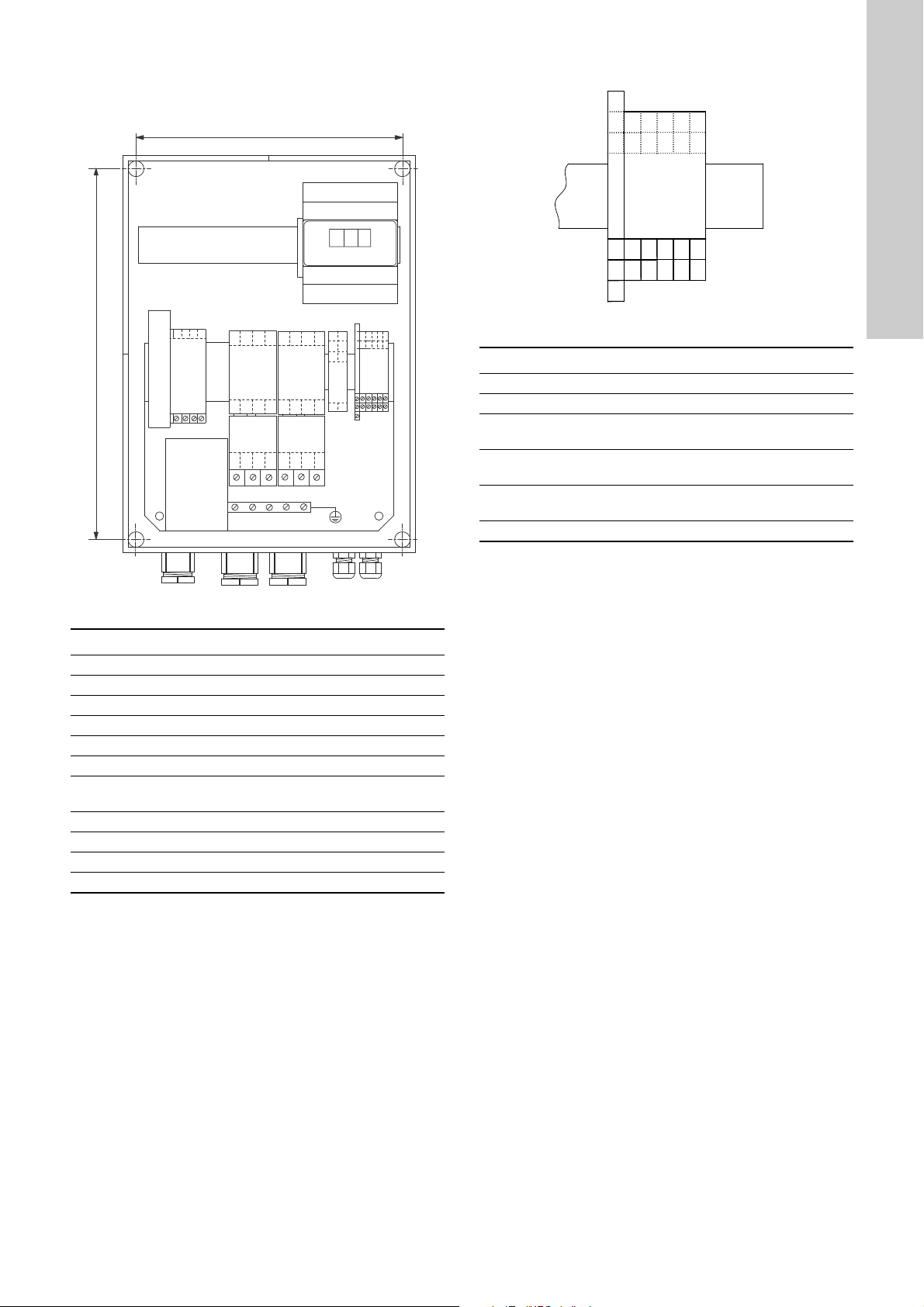
3.1 Controller cabinet
3.2 Terminal block
Fig. 2 Terminal block for sensor and alarm devices (LCD)
Pos. Description
1-2-3 Output for external high-level alarm device (NO-NC)
T11-T21 Input for motor PTC resistance/thermal switch
T12-T22
lo-Ub
41-42 Input for high-level float switch (optional)
Input for second motor PTC resistance/thermal
switch. Only LCD.
Input for analog level sensor. Ub delivers a 24 VDC
voltage to the CU 215.
Output for external overtemperature alarm device
4-5
(NO)
English (GB)
TM06 1921 3314
Fig. 1 Internal construction of the LCD 115, 12-23A, DOL
Pos. Description
1 CU 215 module
2 Terminal block for sensor and alarm devices. See fig. 2.
3 High-level relay
4 Contactor
5 Overload relay. Only DOL.
6 Terminal block for power supply
Fuse holders for control circuit fuses (1 to 3 depending
7
on current/voltage variant)
8 Isolation transformer
9 Earth bar
10 Cable glands
11 Holes for mounting screws
TM06 2742 4614
3
Page 4

4. Installation
Note
Caution
Note
M1 M2
3 - NC T21
2 - NO T11
T22
T12
5
4
Ub
Io
42
41
1 - COM
4-20
mA
PE
LNLN
English (GB)
Warning
Before starting any work on pumps used to pump
liquids which could be constituted as being
hazardous to health, thorough cleaning/venting
of pumps, pits, etc. must be carried out
according to local regulations.
Warning
Before making any connections in the controller
or work on pumps, pits, etc., switch off the power
supply. Make sure that it cannot be accidentally
switched on.
The installation must be carried out by authorised staff in
accordance with local regulations.
4.1 Location
Warning
In potentially explosive areas, the float switch, if
any, must be connected via an Ex-barrier, e.g.
Grundfos LC-Ex4 Zener barrier (No. 96440300).
Use only float switches approved for use in
potentially explosive areas.
Install the controller and the Ex-barrier outside
the potentially explosive area.
The controller can be installed at ambient temperatures from
-20 to 50 °C.
When installed outdoors, the controller must be placed in a
protective shed or cupboard. It must not be exposed to direct
sunlight.
The maximum length of the sensor cable is 30 m.
4.2 Mounting the cabinet
1. Remove the transport protectors, if any, from inside the
cabinet.
2. Mount the cabinet on a plane wall with screws through the
mounting holes. See fig. 1.
The cable glands must point downwards.
Fit additional cable glands to the base of the
cabinet, if necessary.
4.3 Connecting the cabinet
Make sure that a 250 mA backup fuse is installed
in the fuse holder. See pos. 6 in fig. 1.
Connect the following devices to the controller:
• Level sensor. See fig. 3.
• Power supply. See fig. 4.
• Pump(s). See fig. 4.
Optional:
• Overtemperature protection. See fig. 3.
• High-level float switch. See fig. 3.
• External high-level alarm device. See fig. 3.
• External overtemperature alarm device. See fig. 3.
See also the wiring diagram delivered with the product.
Connect the screen of the conductor from the
level sensor via a metal bracket to the earthed
metal backplate of the cabinet.
Fig. 3 Connecting sensor and alarm devices
4
TM06 2108 3714
Page 5

The following diagrams show how to connect motors and power
PE
1U2 1N2 2U2 2N2
U1
N1
LNPE
T12 T22
T11 T21
1~
NL3L1 L2
T12 T22T11 T21
3~
PE
PE
W1
V1
U1
N1
1U2 1V2 1W2 2U2 2V2 2W2
PE
T12 T22
T11 T21
1~
LNPE
1U2 1N2 2U2 2N2
U1
N1
1U2 1V2 1W2 2U2 2V2 2W2
W1V1U1
N1
L3 NL1 L2
T12 T22T11 T21
3~
PE
PE
supply to the DOL and SS versions. For other versions, please
refer to the wiring diagram delivered with the product.
DOL, single-phase DOL, three-phase
English (GB)
TM06 2126 3714
TM06 2127 3714
SS, single-phase SS, three-phase
TM06 2651 4514
Fig. 4 Connecting motor and power supply for DOL and SS versions
TM06 2652 4514
5
Page 6
5. Choosing the mode
English (GB)
The controller can be set to three modes:
– starting unit
– starting unit with alternation
– level converter.
In an application with pumps, we recommend that you use a
starting unit or starting unit with alternation.
5.1 Starting unit
The controller converts the analog signal from the level sensor
into digital signals. This enables start/stop of the pump at two
setpoints and activation of high-level alarm.
This is the usual setting for a pit with heavy and random flow
intake.
5.2 Starting unit with alternation (LCD only)
The controller enables start/stop of the two pumps alternately.
This mode is ideal for a pit with slow water intake.
5.3 Level converter
The same setpoint is used for start and stop. We do not
recommend this mode in an application with pumps.
6. Reading the display
7. Configuring the controller
The following parameters can be set:
• Mode:
– starting unit
– starting unit with alternation
– level converter.
• Range of the level sensor (liquid level in metres corresponding
to 20 mA).
• Setpoints S1, S2, S3 and S4.
1. Scroll through the parameters using the up and down buttons
on the display.
2. To change a parameter, press [ ● ] for eight seconds. The first
digit flashes and can be changed.
3. Press the button again to select the next digit.
4. When you have selected the last digit, press the button again.
The display will cease to flash, and the parameter has been
changed.
Reactions if none of the buttons are pressed for eight seconds:
• When scrolling through the parameters:
The display reverts to its original state, and the diodes revert
to the normal displaying of the liquid level.
• When changing a parameter:
The parameter is set to the actual value shown in the display,
and the display ceases to flash.
Setting the mode
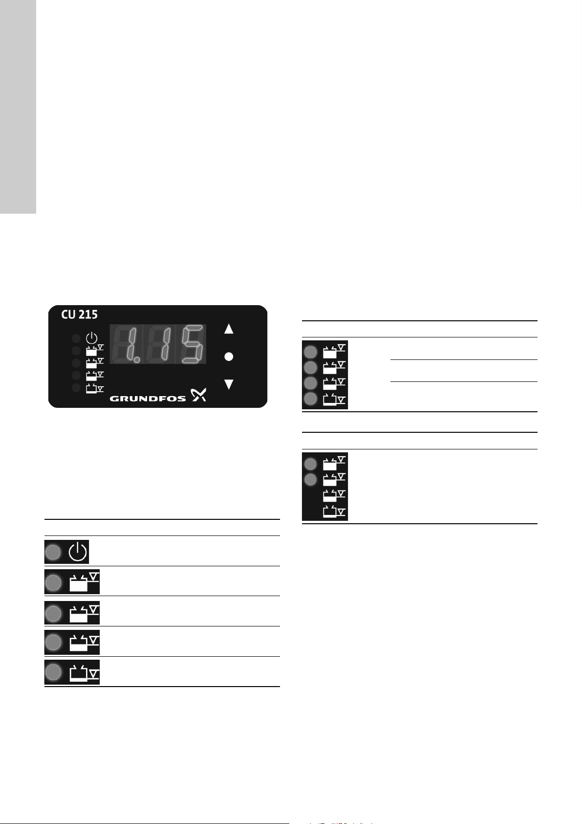
Fig. 5 Display of the CU 215
When the controller is connected to the power supply and
properly connected to the level sensor, the CU 215 module shows
the liquid level.
If the level sensor is not properly connected, the display will show
"---".
The four orange light diodes correspond to four configurable relay
outputs: S1, S2, S3 and S4. Each of them corresponds to a liquid
level. See table below.
LED Colour Description
Green
Orange
Orange
The CU 215 is functioning
normally.
Output S4 is activated. The level
is higher than setpoint S4.
Output S3 is activated. The level
is higher than setpoint S3.
LED Indicator Description
All LEDs
on.
TM06 2104 3714
Setting the range
LED Description
LED 1
and 2 on.
LvL: Level converter.
StA: Starting unit.
S.t.A.: Starting unit with alternation of
pump 1 and 2. Only LCD.
Range of the level sensor (liquid level
in metres corresponding to 20 mA).
Max. 10 m.
Orange
Orange
Output S2 is activated. The level
is higher than setpoint S2.
Output S1 is activated. The level
is higher than setpoint S1.
6
Page 7

Setting the setpoints
Note
Note
Starting unit
LED Indicator Description
LED 1 on.
LED 1
flashing.
LED 2 on.
LED 2
flashing.
S1: Start level of pump 1.
Must be ≤ S2.
S1: Stop level of pump 1.
Must be ≤ S1.
S2: Start level of pump 2.
Must be ≤ S3.
Only LCD.
S2: Stop level of pump 2.
Must be ≤ S2.
Only LCD.
Level converter
LED Indicator Description
LED 1 on.
LED 2 on.
LED 3 on.
LED 4 on. S4: High-level alarm 2.
S1: Start and stop level of pump 1.
Must be ≤ S2.
S2: Start and stop level of pump 2.
Must be ≤ S3.
Only LCD.
S3: High-level alarm 1.
Must be ≤ S4.
English (GB)
LED 3 on.
LED 4 on. S4: High-level alarm 2.
In starting unit mode, we recommend that you set
the stop level below the start level. It will prevent
frequent starts/stops of the pump.
If you attempt to change a parameter to an invalid
value, for example 99.0 in the level sensor range,
the parameter reverts to its original value when
the display ceases to flash.
S3: High-level alarm 1.
Must be ≤ S4.
7
Page 8

8. Maintenance
Note
English (GB)
Warning
Before starting any work on pumps used to pump
liquids which could be constituted as being
hazardous to health, thorough cleaning/venting
of pumps, pits, etc. must be carried out
according to local regulations.
Warning
Before making any connections in the controller
or work on pumps, pits, etc., switch off the power
supply. Make sure that it cannot be accidentally
switched on.
We recommend that you carry out minor checks of the controller,
pump pits, tanks, pumps, etc. at regular intervals.
These checks must be carried out by authorised staff.
• Check the gaskets of the cable glands and on the front of the
cabinet.
• Check for possible deposits/sludge build-up in the pump pit/
tank. Sludge may settle in areas with almost stagnant liquid.
• Check for possible blockage on the inlet side of the pump.
A blockage will typically be a large solid object.
• If the controller has been installed in a particularly aggressive
environment, we recommend that you check the motor
protection contacts in order to identify possible chemical
attack resulting in corrosion. In typical installations, the motor
protection contacts will work for several years and do not
require any inspection.
The above list is not complete. The controller
may be installed in systems, installations and/or
environments which require thorough and
regular maintenance.
9. Technical data
Voltage variants, rated voltages
• 1 x 230 V.
• 3 x 230/400 V.
Voltage tolerances
- 15 %/+ 10 % of rated voltage.
See also installation and operating instructions for the pump in
question.
Mains frequency
50/60 Hz.
See also installation and operating instructions for the pump in
question.
Supply system earthing
For TN systems and TT systems.
Short-circuit protection of power supply
Depending on variant. See nameplate.
Ambient temperature
• During operation: -20 - 50 °C (must not be exposed to direct
sunlight).
• In stock: -30 - 60 °C.
Enclosure class
IP65.
EMC (electromagnetic compatibility)
According to EN 61 000-6-2 and EN 61 000-6-3.
Material
ABS (acrylonitrile butadiene styrene).
Weight
Depending on variant. See nameplate.
Dimensions including cable glands
• LC, LCD 115 1-23A DOL: 410 x 280 x 150 mm.
• LC, LCD 115 9.2-25A SS: 410 x 280 x 150 mm.
• LC 115 14-43A SS: 600 x 280 x 195 mm.
• LCD 115 14-43A SS: 600 x 500 x 210 mm.
• LC, LCD 115 12A 40: 600 x 280 x 150 mm.
• LC, LCD 115 12A 40/150: 600 x 280 x 150 mm.
Outputs for alarm devices
Max. 230 VAC / max. 2 A / min. 10 mA / AC1.
Accuracy of sensor/controller
• ± 0.3 % of range, ± 1 digit.
8
Page 9
10. Fault finding
Warning
Before starting any work on pumps used to pump
liquids which could be constituted as being
hazardous to health, thorough cleaning/venting
of pumps, pits, etc. must be carried out according
to local regulations.
Warning
Before making any connections in the controller
or work on pumps, pits, etc., switch off the power
supply. Make sure that it cannot be accidentally
switched on.
Fault Cause Remedy
1. The pump does not run
even though the liquid level
is higher than the start level
of the pump.
2. The pump is starting/
stopping too frequently.
See also installation and operating instructions for the pump in
question.
a) No power supply. None of the indicator lights
are on.
b) Control circuit fuses are blown. Check and eliminate the cause. Replace the
c) The motor protection relay has cut out the
pump.
d) The PTC resistance/thermal switch has cut
out the pump.
e) An external alarm device, if any, is activated.
f) The control circuit for the motor protection
relay has been broken or fails.
g) Motor/supply cable is defective. Check motor and cable.
h) The level sensor is defective. Check level sensor and cable.
i) The CU 215 module is defective. Replace the module.
a) The level sensor is defective. Check level sensor and cable.
Switch on the power supply.
control circuit fuses. See pos. 6 in fig. 1.
Check the pump/pit.
Allow the pump to cool. The pump will restart
automatically according the signal from the level
sensor.
Check the control circuit.
English (GB)
11. Disposal
This product or parts of it must be disposed of in an
environmentally sound way:
1. Use the public or private waste collection service.
2. If this is not possible, contact the nearest Grundfos company
or service workshop.
Subject to alterations.
9
Page 10

Declaration of conformity
Declaration of conformity 1
GB: EC declaration of conformity
We, Grundfos, declare under our sole responsibility
that the product LC, LCD 115, to which this
declaration relates, is in conformity with these
Council directives on the approximation of the laws
of the EC member states:
DE: EG-Konformitätserklärung
Wir, Grundfos, erklären in alleiniger Verantwortung,
dass das Produkt LC, LCD 115, auf das sich diese
Erklärung bezieht, mit den folgenden Richtlinien
des Rates zur Angleichung der Rechtsvorschriften
der EU-Mitgliedsstaaten übereinstimmt:
ES: Declaración CE de
conformidad
Nosotros, Grundfos, declaramos bajo nuestra
propia responsabilidad que el producto LC, LCD
115, al cual se refiere esta declaración, está
conforme con las Directivas del Consejo en la
aproximación de las leyes de los Estados
Miembros del EM:
DK: EF-
overensstemmelseserklæring
Vi, Grundfos, erklærer under ansvar at produktet
LC, LCD 115 som denne erklæring omhandler, er i
overensstemmelse med disse af Rådets direktiver
om indbyrdes tilnærmelse til EF-medlemsstaternes
lovgivning:
GR: ∆ήλωση συμμόρφωσης EC
Εμείς, η Grundfos, δηλώνουμε με αποκλειστικά
δική μας ευθύνη ότι τα προϊόντα LC, LCD 115, στα
οποία αναφέρεται η παρούσα δήλωση,
συμμορφώνονται με τις εξής Οδηγίες του
Συμβουλίου περί προσέγγισης των νομοθεσιών
των κρατών μελών της ΕΕ:
IT: Dichiarazione di conformità CE
Grundfos dichiara sotto la sua esclusiva
responsabilità che il prodotto LC, LCD 115, al quale
si riferisce questa dichiarazione, è conforme alle
seguenti direttive del Consiglio riguardanti il
riavvicinamento delle legislazioni degli Stati membri
CE:
HU: EK megfelelőségi nyilatkozat
Mi, a Grundfos, egyedüli felelősséggel kijelentjük,
hogy a LC, LCD 115 termék, amelyre jelen
nyilatkozik vonatkozik, megfelel az Európai Unió
tagállamainak jogi irányelveit összehangoló tanács
alábbi előírásainak:
PL: Deklaracja zgodności WE
My, Grundfos, oświadczamy z pełną
odpowiedzialnością, że nasze wyroby LC, LCD
115, których deklaracja niniejsza dotyczy, są
zgodne z następującymi wytycznymi Rady d/s
ujednolicenia przepisów prawnych krajów
członkowskich WE:
FI: EY-
vaatimustenmukaisuusvakuut
us
Me, Grundfos, vakuutamme omalla vastuullamme,
että tuote
LC, LCD 115, jota tämä vakuutus koskee, on EY:n
jäsenvaltioiden lainsäädännön
yhdenmukaistamiseen tähtäävien Euroopan
neuvoston direktiivien vaatimusten mukainen
seuraavasti:
NL: EC
overeenkomstigheidsverklarin
g
Wij, Grundfos, verklaren geheel onder eigen
verantwoordelijkheid dat het product LC, LCD 115
waarop deze verklaring betrekking heeft, in
overeenstemming is met de Richtlijnen van de
Raad in zake de onderlinge aanpassing van de
wetgeving van de EG lidstaten betreffende:
RU: Декларация о соответствии
ЕС
Мы, компания Grundfos, со всей
ответственностью заявляем, что изделия LC,
LCD 115, к которым относится настоящая
декларация, соответствуют следующим
Директивам Совета Евросоюза об унификации
законодательных предписаний стран-членов ЕС:
SE: EG-försäkran om
överensstämmelse
Vi, Grundfos, försäkrar under ansvar att produkten
LC, LCD 115, som omfattas av denna försäkran, är
i överensstämmelse med rådets direktiv om
inbördes närmande till EU-medlemsstaternas
lagstiftning, avseende:
10
Page 11

— Machinery Directive (2006/42/EC).
Standard used: EN 60204-1:2006.
— Low Voltage Directive (2006/95/EC).
Standard used: EN 60439-1:2004.
— EMC Directive (2004/108/EC).
Standards used: EN 61 000-6-2:2005 and
EN 61000-6-3:2007.
Bjerringbro, 12 January 2015
Jan Strandgaard
Technical Director
Grundfos Holding A/S
Poul Due Jensens Vej 7
8850 Bjerringbro, Denmark
Person authorised to compile the technical file and
empowered to sign the EC declaration of conformity.
Declaration of conformity
11
Page 12

Declaration of conformity RU
Declaration of conformity RU 2
Электрические блоки управления насосами серии LC, LCD с
комплектующими и запасными частями к ним и Низковольтные
комплектные устройства серии «Control» сертифицированы на
соответствие требованиям Технических регламентов Таможенного
союза ТР ТС 020/2011 «Электромагнитная совместимость
технических средств»; TP TC 004/2011 «О безопасности
низковольтного оборудования».
Сертификат соответствия:
№ ТС RU C-DK.АИ30.В.01166, срок действия до 07.12.2019г.
№ TC RU C-RU.АИ30.В.01231, срок действия
до 23.12.2019г.
Низковольтные комплектные устройства серии «Control»,
произведенные в России, изготовлены в соответствии с ТУ 3432-021-
59379130-2014
Истра, 1 февраля 2015 г.
Руководитель отдела качества,
экологии и охраны труда
ООО Грундфос Истра, Россия
143581, Московская область,
Касаткина В. В.
Истринский район,
дер. Лешково, д.188
12
Page 13

Argentina
Bombas GRUNDFOS de Argentina S.A.
Ruta Panamericana km. 37.500 Centro
Industrial Garin
1619 Garín Pcia. de B.A.
Phone: +54-3327 414 444
Telefax: +54-3327 45 3190
Australia
GRUNDFOS Pumps Pty. Ltd.
P.O. Box 2040
Regency Park
South Australia 5942
Phone: +61-8-8461-4611
Telefax: +61-8-8340 0155
Austria
GRUNDFOS Pumpen Vertrieb Ges.m.b.H.
Grundfosstraße 2
A-5082 Grödig/Salzburg
Tel.: +43-6246-883-0
Telefax: +43-6246-883-30
Belgium
N.V. GRUNDFOS Bellux S.A.
Boomsesteenweg 81-83
B-2630 Aartselaar
Tél.: +32-3-870 7300
Télécopie: +32-3-870 7301
Belarus
Представительство ГРУНДФОС в
Минске
220125, Минск
ул. Шафарнянская, 11, оф. 56, БЦ
«Порт»
Тел.: +7 (375 17) 286 39 72/73
Факс: +7 (375 17) 286 39 71
E-mail: minsk@grundfos.com
Bosna and Herzegovina
GRUNDFOS Sarajevo
Zmaja od Bosne 7-7A,
BH-71000 Sarajevo
Phone: +387 33 592 480
Telefax: +387 33 590 465
www.ba.grundfos.com
e-mail: grundfos@bih.net.ba
Brazil
BOMBAS GRUNDFOS DO BRASIL
Av. Humberto de Alencar Castelo Branco,
630
CEP 09850 - 300
São Bernardo do Campo - SP
Phone: +55-11 4393 5533
Telefax: +55-11 4343 5015
Bulgaria
Grundfos Bulgaria EOOD
Slatina District
Iztochna Tangenta street no. 100
BG - 1592 Sofia
Tel. +359 2 49 22 200
Fax. +359 2 49 22 201
email: bulgaria@grundfos.bg
Canada
GRUNDFOS Canada Inc.
2941 Brighton Road
Oakville, Ontario
L6H 6C9
Phone: +1-905 829 9533
Telefax: +1-905 829 9512
China
GRUNDFOS Pumps (Shanghai) Co. Ltd.
10F The Hub, No. 33 Suhong Road
Minhang District
Shanghai 201106
PRC
Phone: +86 21 612 252 22
Telefax: +86 21 612 253 33
Croatia
GRUNDFOS CROATIA d.o.o.
Buzinski prilaz 38, Buzin
HR-10010 Zagreb
Phone: +385 1 6595 400
Telefax: +385 1 6595 499
www.hr.grundfos.com
Czech Republic
GRUNDFOS s.r.o.
Čajkovského 21
779 00 Olomouc
Phone: +420-585-716 111
Telefax: +420-585-716 299
Denmark
GRUNDFOS DK A/S
Martin Bachs Vej 3
DK-8850 Bjerringbro
Tlf.: +45-87 50 50 50
Telefax: +45-87 50 51 51
E-mail: info_GDK@grundfos.com
www.grundfos.com/DK
Estonia
GRUNDFOS Pumps Eesti OÜ
Peterburi tee 92G
11415 Tallinn
Tel: + 372 606 1690
Fax: + 372 606 1691
Finland
OY GRUNDFOS Pumput AB
Mestarintie 11
FIN-01730 Vantaa
Phone: +358-(0)207 889 900
Telefax: +358-(0)207 889 550
France
Pompes GRUNDFOS Distribution S.A.
Parc d’Activités de Chesnes
57, rue de Malacombe
F-38290 St. Quentin Fallavier (Lyon)
Tél.: +33-4 74 82 15 15
Télécopie: +33-4 74 94 10 51
Germany
GRUNDFOS GMBH
Schlüterstr. 33
40699 Erkrath
Tel.: +49-(0) 211 929 69-0
Telefax: +49-(0) 211 929 69-3799
e-mail: infoservice@grundfos.de
Service in Deutschland:
e-mail: kundendienst@grundfos.de
HILGE GmbH & Co. KG
Hilgestrasse 37-47
55292 Bodenheim/Rhein
Germany
Tel.: +49 6135 75-0
Telefax: +49 6135 1737
e-mail: hilge@hilge.de
Greece
GRUNDFOS Hellas A.E.B.E.
20th km. Athinon-Markopoulou Av.
P.O. Box 71
GR-19002 Peania
Phone: +0030-210-66 83 400
Telefax: +0030-210-66 46 273
Hong Kong
GRUNDFOS Pumps (Hong Kong) Ltd.
Unit 1, Ground floor
Siu Wai Industrial Centre
29-33 Wing Hong Street &
68 King Lam Street, Cheung Sha Wan
Kowloon
Phone: +852-27861706 / 27861741
Telefax: +852-27858664
Hungary
GRUNDFOS Hungária Kft.
Park u. 8
H-2045 Törökbálint,
Phone: +36-23 511 110
Telefax: +36-23 511 111
India
GRUNDFOS Pumps India Private Limited
118 Old Mahabalipuram Road
Thoraipakkam
Chennai 600 096
Phone: +91-44 2496 6800
Indonesia
PT GRUNDFOS Pompa
Jl. Rawa Sumur III, Blok III / CC-1
Kawasan Industri, Pulogadung
Jakarta 13930
Phone: +62-21-460 6909
Telefax: +62-21-460 6910 / 460 6901
Ireland
GRUNDFOS (Ireland) Ltd.
Unit A, Merrywell Business Park
Ballymount Road Lower
Dublin 12
Phone: +353-1-4089 800
Telefax: +353-1-4089 830
Italy
GRUNDFOS Pompe Italia S.r.l.
Via Gran Sasso 4
I-20060 Truccazzano (Milano)
Tel.: +39-02-95838112
Telefax: +39-02-95309290 / 95838461
Japan
GRUNDFOS Pumps K.K.
Gotanda Metalion Bldg., 5F,
5-21-15, Higashi-gotanda
Shiagawa-ku, Tokyo
141-0022 Japan
Phone: +81 35 448 1391
Telefax: +81 35 448 9619
Korea
GRUNDFOS Pumps Korea Ltd.
6th Floor, Aju Building 679-5
Yeoksam-dong, Kangnam-ku, 135-916
Seoul, Korea
Phone: +82-2-5317 600
Telefax: +82-2-5633 725
Latvia
SIA GRUNDFOS Pumps Latvia
Deglava biznesa centrs
Augusta Deglava ielā 60, LV-1035, Rīga,
Tālr.: + 371 714 9640, 7 149 641
Fakss: + 371 914 9646
Lithuania
GRUNDFOS Pumps UAB
Smolensko g. 6
LT-03201 Vilnius
Tel: + 370 52 395 430
Fax: + 370 52 395 431
Malaysia
GRUNDFOS Pumps Sdn. Bhd.
7 Jalan Peguam U1/25
Glenmarie Industrial Park
40150 Shah Alam
Selangor
Phone: +60-3-5569 2922
Telefax: +60-3-5569 2866
Mexico
Bombas GRUNDFOS de México S.A. de
C.V.
Boulevard TLC No. 15
Parque Industrial Stiva Aeropuerto
Apodaca, N.L. 66600
Phone: +52-81-8144 4000
Telefax: +52-81-8144 4010
Netherlands
GRUNDFOS Netherlands
Velu we zoom 3 5
1326 AE Almere
Postbus 22015
1302 CA ALMERE
Tel.: +31-88-478 6336
Telefax: +31-88-478 6332
E-mail: info_gnl@grundfos.com
New Zealand
GRUNDFOS Pumps NZ Ltd.
17 Beatrice Tinsley Crescent
North Harbour Industrial Estate
Albany, Auckland
Phone: +64-9-415 3240
Telefax: +64-9-415 3250
Norway
GRUNDFOS Pumper A/S
Strømsveien 344
Postboks 235, Leirdal
N-1011 Oslo
Tlf.: +47-22 90 47 00
Telefax: +47-22 32 21 50
Poland
GRUNDFOS Pompy Sp. z o.o.
ul. Klonowa 23
Baranowo k. Poznania
PL-62-081 Przeźmierowo
Tel: (+48-61) 650 13 00
Fax: (+48-61) 650 13 50
Portugal
Bombas GRUNDFOS Portugal, S.A.
Rua Calvet de Magalhães, 241
Apartado 1079
P-2770-153 Paço de Arcos
Tel.: +351-21-440 76 00
Telefax: +351-21-440 76 90
Romania
GRUNDFOS Pompe România SRL
Bd. Biruintei, nr 103
Pantelimon county Ilfov
Phone: +40 21 200 4100
Telefax: +40 21 200 4101
E-mail: romania@grundfos.ro
Russia
ООО Грундф ос Россия
109544, г. Москва, ул. Школьная, 39-41,
стр. 1
Тел. (+7) 495 564-88-00 (495) 737-30-00
Факс (+7) 495 564 88 11
E-mail grundfos.moscow@grundfos.com
Serbia
Grundfos Srbija d.o.o.
Omladinskih brigada 90b
11070 Novi Beograd
Phone: +381 11 2258 740
Telefax: +381 11 2281 769
www.rs.grundfos.com
Singapore
GRUNDFOS (Singapore) Pte. Ltd.
25 Jalan Tukang
Singapore 619264
Phone: +65-6681 9688
Telefax: +65-6681 9689
Slovakia
GRUNDFOS s.r.o.
Prievozská 4D
821 09 BRATISLAVA
Phona: +421 2 5020 1426
sk.grundfos.com
Slovenia
GRUNDFOS d.o.o.
Šlandrova 8b, SI-1231 Ljubljana-Črnuče
Phone: +386 31 718 808
Telefax: +386 (0)1 5680 619
E-mail: slovenia@grundfos.si
South Africa
GRUNDFOS (PTY) LTD
Corner Mountjoy and George Allen Roads
Wilbart Ext. 2
Bedfordview 2008
Phone: (+27) 11 579 4800
Fax: (+27) 11 455 6066
E-mail: lsmart@grundfos.com
Spain
Bombas GRUNDFOS España S.A.
Camino de la Fuentecilla, s/n
E-28110 Algete (Madrid)
Tel.: +34-91-848 8800
Telefax: +34-91-628 0465
Sweden
GRUNDFOS AB
Box 333 (Lunnagårdsgatan 6)
431 24 Mölndal
Tel.: +46 31 332 23 000
Telefax: +46 31 331 94 60
Switzerland
GRUNDFOS Pumpen AG
Bruggacherstrasse 10
CH-8117 Fällanden/ZH
Tel.: +41-44-806 8111
Telefax: +41-44-806 8115
Taiwan
GRUNDFOS Pumps (Taiwan) Ltd.
7 Floor, 219 Min-Chuan Road
Taichung, Taiwan, R.O.C.
Phone: +886-4-2305 0868
Telefax: +886-4-2305 0878
Thailand
GRUNDFOS (Thailand) Ltd.
92 Chaloem Phrakiat Rama 9 Road,
Dokmai, Pravej, Bangkok 10250
Phone: +66-2-725 8999
Telefax: +66-2-725 8998
Turkey
GRUNDFOS POMPA San. ve Tic. Ltd. Sti.
Gebze Organize Sanayi Bölgesi
Ihsan dede Caddesi,
2. yol 200. Sokak No. 204
41490 Gebze/ Kocaeli
Phone: +90 - 262-679 7979
Telefax: +90 - 262-679 7905
E-mail: satis@grundfos.com
Ukraine
Бізнес Центр Європа
Столичне шосе, 103
м. Київ, 03131, Україна
Телефон: (+38 044) 237 04 00
Факс.: (+38 044) 237 04 01
E-mail: ukraine@grundfos.com
United Arab Emirates
GRUNDFOS Gulf Distribution
P.O. Box 16768
Jebel Ali Free Zone
Dubai
Phone: +971 4 8815 166
Telefax: +971 4 8815 136
United Kingdom
GRUNDFOS Pumps Ltd.
Grovebury Road
Leighton Buzzard/Beds. LU7 4TL
Phone: +44-1525-850000
Telefax: +44-1525-850011
U.S.A.
GRUNDFOS Pumps Corporation
17100 West 118th Terrace
Olathe, Kansas 66061
Phone: +1-913-227-3400
Telefax: +1-913-227-3500
Uzbekistan
Grundfos Tashkent, Uzbekistan The Representative Office of Grundfos Kazakhstan in
Uzbekistan
38a, Oybek street, Tashkent
Телефон: (+998) 71 150 3290 / 71 150
3291
Факс: (+998) 71 150 3292
Addresses Revised 10.03.2015
Grundfos companies
Page 14

98770282 0215
ECM: 1152933
www.grundfos.com
The name Grundfos, the Grundfos logo, and be think innovate are registered trademarks owned by Grundfos Holding A/S or Grundfos A/S, Denmark. All rights reserved worldwide. © Copyright Grundfos Holding A/S
 Loading...