

Page 1

LCD 108
Installation and operating instructions
GRUNDFOS INSTRUCTIONS
Page 2

Declaration of Conformity
We, Grundfos, declare under our sole responsibility that the product
LC/LCD 108, to which this declaration relates, is in conformity with these
Council directives on the approximation of the laws of the EC member
states:
— Machinery Directive (98/37/EC).
Standard used: EN 809: 2000.
— Low Voltage Directive (2006/95/EC).
Standards used: EN 60335-1: 2002 and EN 60335-2-51: 2003.
— EMC Directive (2004/108/EC).
Standards used: EN 61000-6-2 and EN 61000-6-3.
Bjerringbro, 15th December 2008
Niels Vinther
Technical Manager
2
Page 3

CONTENTS
Page
1. General 3
1.1 Applications 3
1.2 Variants 3
2. Location and mounting 3
2.1 Location 4
2.2 Mounting of LCD 108 for direct-on-line starting 4
3. Systems for parallel operation with 3 float switches 4
3.1 Electrical connection 4
3.2 Setting 5
3.3 Control panel 7
3.4 Battery back-up functions 7
3.5 Reset button and ON-OFF-AUTO selector switch 8
4. Systems for parallel operation with 4 float switches 8
4.1 Electrical connection 8
4.2 Setting 9
4.3 Control panel 10
4.4 Battery back-up functions 11
4.5 Reset button and ON-OFF-AUTO selector switch 12
5. Systems for 100 % standby operation 13
5.1 Electrical connection 13
5.2 Setting 13
5.3 Control panel 15
5.4 Battery back-up functions 15
5.5 Reset button and ON-OFF-AUTO selector switch 16
6. System for full-control operation 17
6.1 Electrical connection 17
6.2 Setting 17
6.3 Control panel 19
6.4 Battery back-up functions 19
6.5 Reset button and ON-OFF-AUTO selector switch 20
7. Start-up 21
8. Maintenance 21
9. Technical data 21
10. Fault finding chart 22
11. Disposal 22
Before beginning installation procedures, these
installation and operating instructions should be
studied carefully. The installation and operation
should also be in accordance with local regulations
and accepted codes of good practice.
1. General
The LCD 108 controller is designed for the control of pumps in
wastewater systems.
Type key:
1.1 Applications
The LCD 108 enables:
• control of two pumps based on signals from float switches,
• automatic pump changeover (even distribution of operating
hours on both pumps),
• selection of automatic test run during long periods of inactivity
(every 24 hours),
• battery back-up in case of mains supply failure (accessory for
certain variants),
• starting delay within the range from 0 to 255 sec. (random)
after returning from battery operation to mains operation
(resulting in an even mains load when several pumping
stations are started up at the same time),
• selection of automatic alarm resetting,
• selection of automatic restarting,
• setting of stop delays matching the actual operating
conditions,
• indication of liquid level,
• alarm indication of:
- inadmissibly high liquid level,
- overload (via motor protection relay),
- overtemperature (via PTC resistance or thermal switch in
motor),
- wrong phase sequence (only certain variants),
- mains supply failure (only certain variants),
- defective float switch.
As standard, the LCD 108 has one alarm output for common
alarm. Certain variants have an additional alarm output for
separate high-level alarm.
Furthermore, the controller incorporates a buzzer (only certain
variants).
1.2 Variants
The actual controller type, voltage variant, etc. are stated in the
type key on the nameplate situated on the side of the controller
cabinet.
The LCD 108 is available for direct-on-line starting.
The LCD 108 can be connected and set to operation/control in 4
different ways, see sections 3. to 6.:
• Section 3. Systems for parallel operation with 3 float switches.
(Electrodes can also be used.)
• Section 4. Systems for parallel operation with 4 float switches.
(Electrodes can also be used.)
• Section 5. Systems for 100 % standby operation.
• Section 6. System for full-control operation.
2. Location and mounting
Example LCD 108 400 3 23 SMS
LCD = two-pump controller
108 = type designation
Phase voltage [V]
1 = single-phase
3 = three-phase
Maximum operating current per pump [A]
SMS = with SMS unit
Before starting any work on pumps used to pump
liquids which could be constituted as being
hazardous to health, thorough cleaning/venting of
pumps, pits, etc. must be carried out according to
local regulations.
Before making any connections in the LCD 108 or
work on pumps, pits, etc., it must be ensured that the
electricity supply has been switched off and that it
cannot be accidentally switched on.
The installation must be carried out by authorized personnel in
accordance with local regulations.
3
Page 4

2.1 Location
22
12
T21
T11
T22
T12
H-NOH-COM
H-NC
G-NO
G-COM
G-NC
21
11
32
42
31
41
The LCD 108 controller and an EEx barrier, if
required, must not be installed in explosion hazard
areas.
Only float switches approved for use in explosion
hazard areas may be used. The float switches must
be connected via an EEx barrier, e.g. Grundfos
number 96440300.
The LCD 108 can be mounted at ambient temperatures ranging
from –30 °C to +50 °C.
Enclosure class: IP 65.
When installed outdoors, the LCD 108 must be placed in a
protective shed or cupboard.
The LCD 108 must not be exposed to direct sunlight.
2.2 Mounting of LCD 108 for direct-on-line starting
Before mounting, remove the transport protectors, if any, from
inside the cabinet.
Mount the LCD 108:
• on a plane wall surface,
• with the Pg cable entries pointing downwards
(additional Pg cable entries, if required, must be fitted in the
bottom plate of the cabinet),
• with four screws through the mounting holes in the back plate
of the cabinet. The mounting holes must be bored with a 4 mm
bore. Fit the screws into the mounting holes and tighten
securely. Fit the plastic caps supplied with the controller on the
screws (IP 65).
Figure 1 shows the terminals listed under positions 2 and 3.
3. Systems for parallel operation with 3 float
switches
Description (see also page 23 or 24):
The pumps are controlled by the liquid level in the pit.
• When the float switch, pos. 1, registers liquid, the first pump is
started.
• When the float switch, pos. 2, registers liquid, the next pump is
started.
• When the float switch, pos. 1, does not register any liquid, the
"stop delay" is initiated (can be set). After expiration of the
stop delay, both pumps are stopped.
• The pumps operate alternately.
The top float switch, pos. 3, activates the high-level alarm.
Before starting any work on pumps used to pump
liquids which could be constituted as being
hazardous to health, thorough cleaning/venting of
pumps, pits, etc. must be carried out according to
local regulations.
Before making any connections in the LCD 108 or
work on pumps, pits, etc., it must be ensured that the
electricity supply has been switched off and that it
cannot be accidentally switched on.
3.1 Electrical connection
Parallel operation with 3 float switches, pages 23 or 24.
Before starting work on the system, switch off the
supply voltage and lock the mains switch in
position 0.
Any external voltage connected to the system must
be switched off before work is started.
Fig. A1 on page 23.
The figures show all electrical connections required to connect
the LCD 108 for direct-on-line starting, parallel operation with
3 float switches.
Fig. A2 on page 24.
The figure shows all electrical connections required to connect
the LCD 108 for star-delta starting, parallel operation with 3 float
switches.
Fig. 1
Key to the symbols in figs. 1 and 1:
Pos. Description
Terminal block for level inputs
1
(11-12, 21-22, 31-32, 41-42).
Terminal block with:
• input for the PTC resistance/thermal switch of the
motor (T11-T21, T12-T22),
2
• output for external alarm device for high-level alarm
(H-NC, H-COM, H-NO) (only certain variants),
• output for external alarm device for common alarm
(G-NC, G-COM, G-NO).
Note: If the distance between the controller and pit exceeds
20 metres, it is not advisable to use electrodes as problems with
the signal values sent back to the controller may arise.
In such cases, it is recommended to use float switches.
Note: Cables of up to 100 metres can be connected between the
controller and the float switches.
4
TM01 4833 2308
The LCD 108 must be connected in accordance with
the rules and standards in force for the application in
question.
The operating voltage and frequency are marked on the controller
nameplate. Make sure that the controller is suitable for the
electricity supply on which it will be used.
All cables/wires must be fitted through the Pg cable entries and
gaskets (IP 65).
Maximum back-up fuse is stated on the controller nameplate.
If required according to local regulations, an external mains
switch must be installed.
Note: If the PTC resistance/thermal switch of the motor is
connected, the factory-fitted short-circuit jumper must be
removed (terminals T11-T21, T12-T22). For correct installation of
PTC resistor/thermal switch, see the installation and operating
instructions of the pump.
Single-phase motors must be connected to an external operating
capacitor and in certain cases also to a starting capacitor. Further
details can be found in the installation and operating instructions
for the pump in question.
Float switches placed in an explosion hazard area
must be connected via an EEx barrier, e.g. Grundfos
number 96440300.
The EEx barrier must not be installed in the explosion
hazard area.
Equipment used in explosion hazard areas must in
each individual case have been approved for this
particular application. Furthermore, the cables into
the explosion hazard area must be laid in accordance
with local regulations.
Page 5

Note: Float switches of the same type as Grundfos product
number 96003332 or 96003695, i.e. float switches with
gold-plated contacts suitable for low voltages and currents (40 V/
100 mA), must be used. All EEx-approved float switches are also
suitable.
The float switches must be connected as NO contacts, i.e. brown
and black leads, when float switches, Grundfos product number
96003332 or 96003695, are used.
Key to the symbols in fig. A1 on page 23 and fig. A2 on
page 24:
Pos. Description
Float switch for start of the first pump/
1
common stop.
2 Float switch for start of the next pump. 21-22
3 Float switch for high-level alarm. 31-32
Terminal
number
11- 12
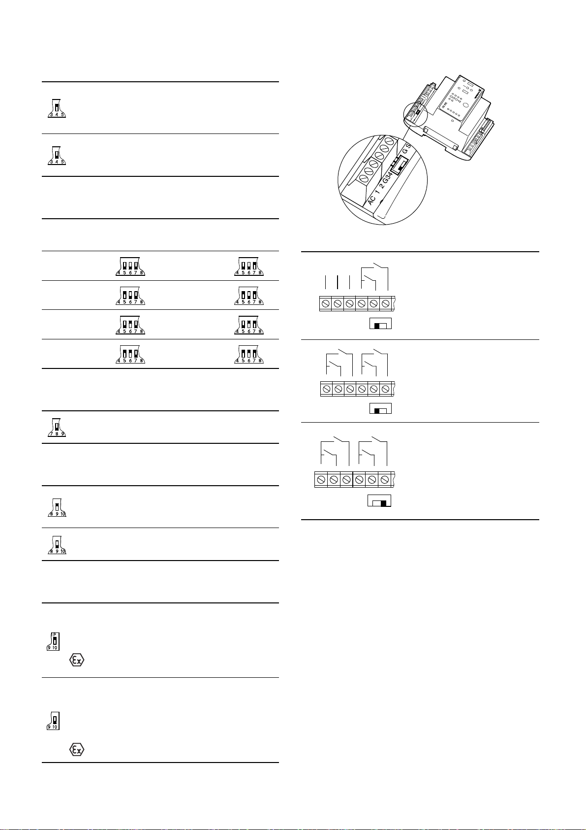
3.2 Setting
Parallel operation with 3 float switches, pages 23 and 24.
The module CU 212 has a 10-pole DIP switch in the bottom right
corner, see fig. 2.
Note: During the setting of the DIP switch, the controller must
always be dead for at least 1 minute to achieve the correct
configuration during start-up after change of the DIP switch
setting.
The DIP switch setting offers the following possibilities:
• selection of starting delay and automatic test run (switch 4),
• setting of stop delay (switches 5, 6 and 7),
• selection of automatic alarm resetting (switch 9),
• selection of automatic restarting (switch 10).
At this setting, the start-up is delayed within the range
from 0 to 255 sec. (random) after the electricity supply
has been switched on when the liquid level is
sufficiently high.
Automatic test run carried out every 24 hours.
After the electricity has been switched on, the pump will
start immediately when the liquid level is sufficiently
high.
No automatic test run.
• Switches 5, 6 and 7, stop delay:
When the DIP switch setting is changed, the controller must
be switched off for at least 1 minute!
The stop delay is the time from the stop signal is given until the
pump is stopped.
It must be ensured that the pump is not running dry.
0 sec. 60 sec.
15 sec. 90 sec.
30 sec. 120 sec.
45 sec. 180 sec.
•Switch 8:
When the DIP switch setting is changed, the controller must
be switched off for at least 1 minute!
Switch 8 has no function in connection with the actual
application (parallel operation with 3 float switches,
pages 23 and 24), but this setting must be maintained!
•Switch 9, automatic alarm resetting:
When the DIP switch setting is changed, the controller must
be switched off for at least 1 minute!
Fig. 2
Set the DIP switch as shown in fig. 2.
Each individual switch (1 to 10) of the DIP switch can be set to
position OFF or ON.
During the setting of the DIP switch, the controller must always
be dead for at least 1 minute to achieve the correct configuration
during start-up after change of the DIP switch setting.
Set the switches 1 to 10 as follows:
•Switches 1, 2 and 3, application type:
When the DIP switch setting is changed, the controller must
be switched off for at least 1 minute!
This setting determines the actual application type
(parallel operation with 3 float switches, pages 23
and 24).
•Switch 4, starting delay and automatic test run
(only in the case of battery back-up):
When the DIP switch setting is changed, the controller must
be switched off for at least 1 minute!
This setting ensures automatic resetting of alarm
signals to external alarm devices and the built-in
buzzer. However, an alarm signal will only be reset if
the cause of the fault no longer exists.
At this setting, the alarm signal must be reset manually
by means of the reset button (the reset button is
described in section 3.5).
•Switch 10, automatic restarting:
When the DIP switch setting is changed, the controller must
be switched off for at least 1 minute!
TM01 6870 2308
This setting enables automatic restarting after the PTC
resistance/thermal switch of the motor has cut out the
pump. Restarting will not be carried out until the motor
has cooled to normal temperature.
When the pumps connected are used in explosion
hazard areas, switch 10 must not be in this
position!
At this setting, the pump must be restarted manually after
the PTC resistance/thermal switch of the motor has cut
out the pump. To restart the pump, push the ON-OFFAUTO selector switch into position OFF for a short period
(the ON-OFF-AUTO selector switch is described in
section 3.5).
When the pumps connected are used in explosion
hazard areas, switch 10 must be in this position!
5
Page 6

AC/DC selector:
AC 1 2
13-18 VAC
0 V
AC
DC
G3 4
AC 1 2
13-18 VAC
0 V
AC
DC
G3 4
AC 1 2
12 VDC
0 V
AC
DC
G3 4
The AC/DC selector switch for electrodes and/or float switches is
placed as shown in fig. 3.
Fig. 3
Operation with electrodes and
float switches:
Selector switch in position AC:
It is possible to connect 3
electrodes (1 as reference
electrode) and 2 float switches.
The controller transmits a 13 to
18 VAC signal.
Operation with float switches:
Selector switch in position AC:
It is possible to connect 4 float
switches.
The controller transmits a 13 to
18 VAC signal.
TM02 5747 3902
Operation with float switches:
Selector switch in position DC:
It is possible to connect 4 float
switches.
Cables of up to 100 metres can be
connected between the controller
and the float switches.
The controller transmits a 12 VDC
signal.
If the distance between the controller and pit exceeds 20 metres,
it is not advisable to use electrodes as problems with the signal
values sent back to the controller may arise. In such cases, it is
recommended to use float switches.
6
Page 7

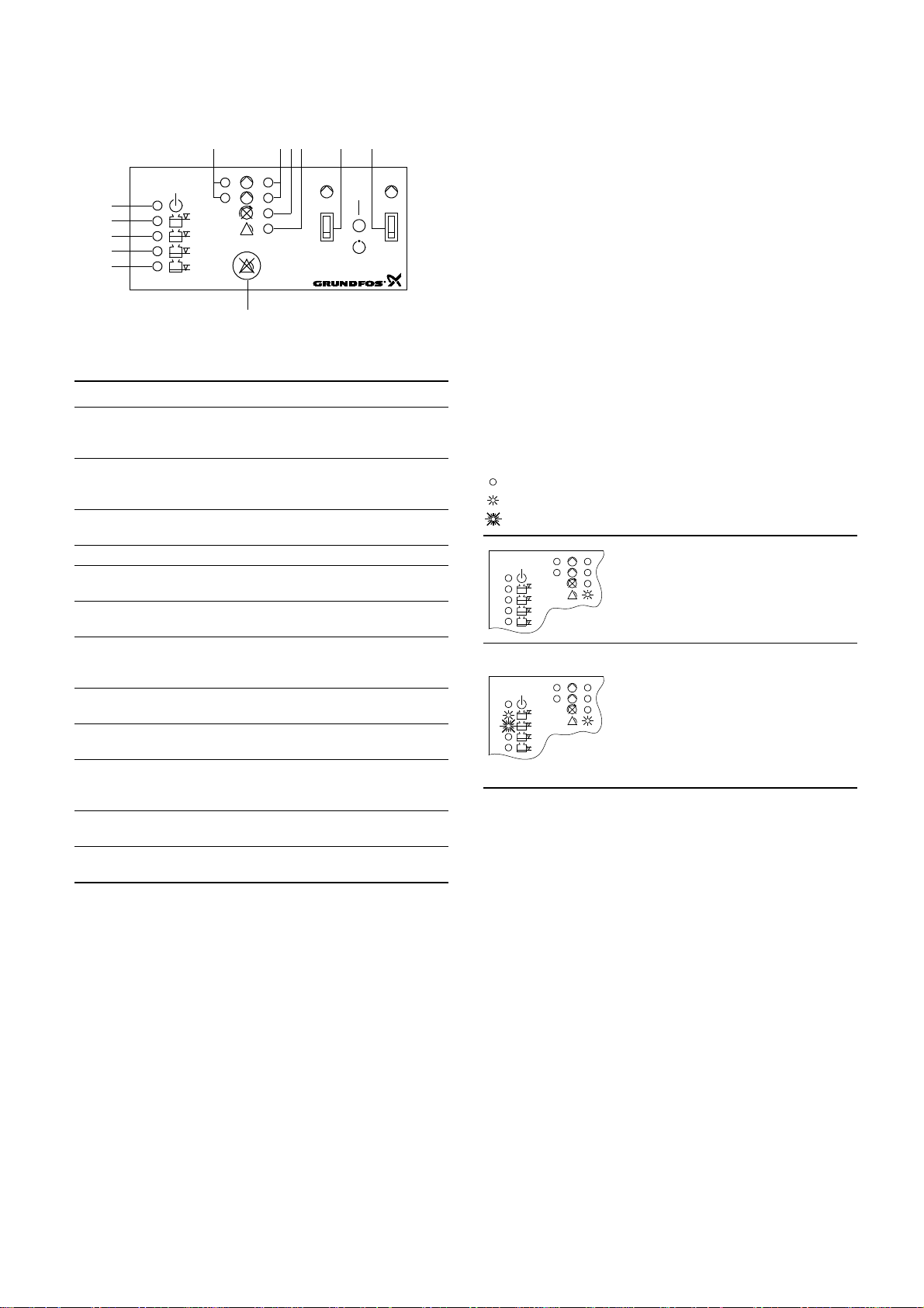
3.3 Control panel
CU 212
21
1
2
1234756
12
11
9
8
10
1
CU 212
2
CU 212
2
1
Parallel operation with 3 float switches, pages 23 and 24.
Figure 4 shows the control panel of the CU 212 module.
Fig. 4
Key to the symbols in fig. 4:
Pos. Description
Green indicator light for pump 1 and 2, indicating
1
starting delay (flashing) and pump operation
(permanently on).
Red indicator light for pump 1 and 2.
2
Flashing: Fault in PTC resistor/thermal switch
On: Fault in motor-protective circuit breaker.
Red indicator light, indicating wrong phase sequence
3
(only certain variants and three-phase pumps only).
4 Red indicator light, indicating common alarm.
ON-OFF-AUTO selector switch for pump 1, three
5
positions, see section 3.5.
ON-OFF-AUTO selector switch for pump 2, three
6
positions, see section 3.5.
Reset button, push-button for manual resetting of alarm
7
signals to external alarm devices and the built-in buzzer
(only certain variants), see section 3.5.
Orange indicator light, which is activated by the float
8
switch for start of the first pump/common stop.
Orange indicator light, which is activated by the float
9
switch for start of the next pump.
Two orange indicator lights, which are activated by the
10
float switch for high-level alarm. In case of high-level
and
alarm, the top indicator light is flashing and the other is
11
permanently on.
Green indicator light, indicating that the electricity
12
supply has been switched on.
The table below shows the situations which may occur if the
normal electricity supply to the LCD 108 fails and a back-up
battery is connected:
= the indicator light is off.
= the indicator light is on.
= the indicator light is flashing.
Mains supply failure:
• The common alarm is active.
The red indicator light is on.
• The green indicator light (electricity
supply switched on) is off.
Mains supply failure and high-level alarm:
TM01 6397 3902
• The common alarm is active.
The red indicator light is on.
• The top orange indicator light is
flashing.
• The second orange indicator light from
the top is on.
• The green indicator light (electricity
supply switched on) is off.
3.4 Battery back-up functions
Parallel operation with 3 float switches, pages 23 and 24.
If a back-up battery for CU 212 (accessory for certain variants) is
installed, the following functions will be carried out if the normal
electricity supply to the LCD 108 fails (see also the illustrations
below):
• The common alarm is active, the red indicator light is on –
cannot be reset!
• If the external alarm device for common alarm is supplied from
an external power source, this device will be active – cannot
be reset by means of the reset button!
• The built-in buzzer (only certain variants) is activated – can be
reset by means of the reset button!
• If the liquid level in the pit rises above the level for high-level
alarm, the top orange indicator light will be flashing and the
second orange indicator light from the top will be permanently
on.
• If the starting delay function and automatic test run were
selected (switch 4 of the DIP switch), the start-up will be
delayed after the electricity supply has been switched on when
the liquid level is sufficiently high, see section 3.2.
7
Page 8

3.5 Reset button and ON-OFF-AUTO selector switch
21
Parallel operation with 3 float switches, pages 23 and 24.
The reset button is a push-button for manual resetting of alarm signals to external alarm devices and the built-in
buzzer (i.e. not for resetting of the alarm memory as this is reset by means of the ON-OFF-AUTO selector switch,
see position OFF ( )).
Even if the fault condition still exists, the external alarm devices and the built-in buzzer will be reset when the reset
button is pressed.
The ON-OFF-AUTO selector switch for each pump has three different positions:
ON ( ), top position:
• The pump will start when the selector switch is pushed into this position (unless the motor protection relay has cut
out the pump).
• If the PTC resistance/thermal switch of the motor registers overtemperature, the pump will not be switched off.
Note: It is the user’s responsibility to decide how long the pump is to run with this fault indication. Over a long
period, the pump will be damaged!
In explosion hazard areas, switch 10 of the DIP switch must be set as stated in section 3.2. Consequently,
the pump cannot be started when the PTC resistance/thermal switch of the motor registers overtemperature.
OFF ( ), middle position:
• The pump cannot start when the selector switch has been set to this position.
• The alarm memory is reset by pushing the selector switch into position OFF ( ). The alarm memory is the light
indication of a fault condition which has disappeared. If a fault condition still exists when the selector switch is
pushed into position ON ( ) or AUTO ( ), the alarm indication will be repeated immediately.
AUTO ( ), bottom position:
• The pump is controlled by the input signals from the float switches and the pump according to the selected
DIP switch setting.
• Alarm signals will automatically be reset. Switch 9 of the DIP switch can, however, be set to manual resetting
which is carried out by means of the reset button, see section 3.2.
• The pump will restart automatically when a given fault condition disappears. However, this is dependent on the
setting of switch 10 of the DIP switch, see section 3.2.
• When the pump starts automatically after a fault condition which has disappeared, the indicator light will continue
to show the fault condition (alarm memory) and the indication can only be removed by resetting the alarm memory,
see position OFF ().
4. Systems for parallel operation with 4 float
switches
Description (see also page 25 or 26):
The pumps are controlled by the liquid level in the pit.
• The float switch, pos. 2, starts the first pump.
• The float switch, pos. 3, starts the next pump.
• The float switch, pos. 1, stops both pumps after expiration of
the "stop delay" (can be set).
• The pumps operate alternately.
• The top float switch, pos. 4, activates the high-level alarm.
Before starting any work on pumps used to pump
liquids which could be constituted as being
hazardous to health, thorough cleaning/venting of
pumps, pits, etc. must be carried out according to
local regulations.
Before making any connections in the LCD 108 or
work on pumps, pits, etc., it must be ensured that the
electricity supply has been switched off and that it
cannot be accidentally switched on.
4.1 Electrical connection
Parallel operation with 4 float switches, pages 25 and 26.
Before starting work on the system, switch off the
supply voltage and lock the mains switch in
position 0.
Any external voltage connected to the system must
be switched off before work is started.
Fig. B1 on page 25.
The figures show all electrical connections required to connect
the LCD 108 for direct-on-line starting, parallel operation with
4 float switches.
Fig. B2 on page 26.
The figure shows all electrical connections required to connect
the LCD 108 for star-delta starting, parallel operation with 4 float
switches.
The LCD 108 must be connected in accordance with
the rules and standards in force for the application in
question.
The operating voltage and frequency are marked on the controller
nameplate. Make sure that the controller is suitable for the
electricity supply on which it will be used.
All cables/wires must be fitted through the Pg cable entries and
gaskets (IP 65).
Maximum back-up fuse is stated on the controller nameplate.
If required according to local regulations, an external mains
switch must be installed.
Note: If the PTC resistance/thermal switch of the motor is
connected, the factory-fitted short-circuit jumper must be
removed (terminals T11-T21, T12-T22). For correct installation of
PTC resistor/thermal switch, see the installation and operating
instructions of the pump.
Single-phase motors must be connected to an external operating
capacitor and in certain cases also to a starting capacitor. Further
details can be found in the installation and operating instructions
for the pump in question.
Float switches placed in an explosion hazard area
must be connected via an EEx barrier, e.g. Grundfos
number 96440300.
The EEx barrier must not be installed in the explosion
hazard area.
Equipment used in explosion hazard areas must in
each individual case have been approved for this
particular application. Furthermore, the cables into
the explosion hazard area must be laid in accordance
with local regulations.
8
Page 9

Note: Float switches of the same type as Grundfos product
number 96003332 or 96003695, i.e. float switches with
gold-plated contacts suitable for low voltages and currents (40 V/
100 mA), must be used. All EEx-approved float switches are also
suitable.
The float switches must be connected as NO contacts, i.e. brown
and black leads, when float switches, Grundfos product number
96003332 or 96003695, are used.
Key to the symbols in fig. B1 on page 25 and fig. B2 on
page 26:
Pos. Description
1 Float switch for common stop. 11-12
2 Float switch for start of the first pump. 21-22
3 Float switch for start of the next pump. 31-32
4 Float switch for high-level alarm. 41-42
Terminal
number
4.2 Setting
Parallel operation with 4 float switches, pages 25 and 26.
The module CU 212 has a 10-pole DIP switch in the bottom right
corner, see fig. 5.
Note: The controller must be off circuit to ensure the correct
configuration during start-up after change of the DIP switch
setting.
The DIP switch setting offers the following possibilities:
• selection of starting delay and automatic test run (switch 4),
• setting of stop delay (switches 5, 6 and 7),
• selection of automatic alarm resetting (switch 9),
• selection of automatic restarting (switch 10).
•Switch 4, starting delay and automatic test run
(only in the case of battery back-up):
When the DIP switch setting is changed, the controller must
be switched off for at least 1 minute!
At this setting, the start-up is delayed within the range
from 0 to 255 sec. (random) after the electricity supply
has been switched on when the liquid level is
sufficiently high.
Automatic test run carried out every 24 hours.
After the electricity has been switched on, the pump will
start immediately when the liquid level is sufficiently
high.
No automatic test run.
• Switches 5, 6 and 7, stop delay:
When the DIP switch setting is changed, the controller must
be switched off for at least 1 minute!
The stop delay is the time from the stop signal is given until the
pump is stopped.
It must be ensured that the pump is not running dry.
0 sec. 60 sec.
15 sec. 90 sec.
30 sec. 120 sec.
45 sec. 180 sec.
Fig. 5
Set the DIP switch as shown in fig. 5. Each individual switch (1 to
10) of the DIP switch can be set to position OFF or ON.
Note: The DIP switch must not be set to other switch
combinations than those described in this section.
Set the switches 1 to 10 as follows:
•Switches 1, 2 and 3, application type:
When the DIP switch setting is changed, the controller must
be switched off for at least 1 minute!
This setting determines the actual application type
(parallel operation with 4 float switches, pages 25 and
26).
•Switch 8:
When the DIP switch setting is changed, the controller must
be switched off for at least 1 minute!
Switch 8 has no function in connection with the actual
application (parallel operation with 4 float switches,
pages 25 and 26), but this setting must be maintained!
•Switch 9, automatic alarm resetting:
When the DIP switch setting is changed, the controller must
be switched off for at least 1 minute!
This setting ensures automatic resetting of alarm
signals to external alarm devices and the built-in
buzzer. However, an alarm signal will only be reset if
the cause of the fault no longer exists.
At this setting, the alarm signal must be reset manually
by means of the reset button (the reset button is
TM04 2341 2308
•Switch 10, automatic restarting:
described in section 4.5).
When the DIP switch setting is changed, the controller must
be switched off for at least 1 minute!
This setting enables automatic restarting after the PTC
resistance/thermal switch of the motor has cut out the
pump. Restarting will not be carried out until the motor
has cooled to normal temperature.
When the pumps connected are used in explosion
hazard areas, switch 10 must not be in this
position!
At this setting, the pump must be restarted manually after
the PTC resistance/thermal switch of the motor has cut
out the pump. To restart the pump, push the ON-OFFAUTO selector switch into position OFF for a short period
(the ON-OFF-AUTO selector switch is described in
section 4.5).
When the pumps connected are used in explosion
hazard areas, switch 10 must be in this position!
9
Page 10

AC/DC selector:
AC 1 2
13-18 VAC
0 V
AC
DC
G3 4
AC 1 2
13-18 VAC
0 V
AC
DC
G3 4
AC 1 2
12 VDC
0 V
AC
DC
G3 4
CU 212
21
1
2
1234756
12
11
9
8
10
The AC/DC selector switch for electrodes and/or float switches is
placed as shown in fig. 6.
Fig. 6
Operation with electrodes and
float switches:
Selector switch in position AC:
It is possible to connect 3
electrodes (1 as reference
electrode) and 2 float switches.
The controller transmits a 13 to
18 VAC signal.
Operation with float switches:
Selector switch in position AC:
It is possible to connect 4 float
switches.
The controller transmits a 13 to
18 VAC signal.
Operation with float switches:
Selector switch in position DC:
It is possible to connect 4 float
switches.
Cables of up to 100 metres can be
connected between the controller
and the float switches.
The controller transmits a 12 VDC
signal.
If the distance between the controller and pit exceeds 20 metres,
it is not advisable to use electrodes as problems with the signal
values sent back to the controller may arise. In such cases, it is
recommended to use float switches.
4.3 Control panel
Parallel operation with 4 float switches, pages 25 and 26.
Figure 7 shows the control panel of the CU 212 module.
Fig. 7
TM02 5747 3902
Key to the symbols in fig. 7:
Pos. Description
Green indicator light for pump 1 and 2, indicating
1
starting delay (flashing) and pump operation
(permanently on).
Red indicator light for pump 1 and 2.
2
Flashing: Fault in PTC resistor/thermal switch
On: Fault in motor-protective circuit breaker.
Red indicator light, indicating wrong phase sequence
3
(only certain variants and three-phase pumps only).
4 Red indicator light, indicating common alarm.
ON-OFF-AUTO selector switch for pump 1, three
5
positions, see section 4.5.
ON-OFF-AUTO selector switch for pump 2, three
6
positions, see section 4.5.
Reset button, push-button for manual resetting of alarm
7
signals to external alarm devices and the built-in buzzer
(only certain variants), see section 4.5.
Orange indicator light, which is activated by the float
8
switch for common stop.
Orange indicator light, which is activated by the float
9
switch for start of the first pump.
Orange indicator light, which is activated by the float
10
switch for start of the next pump.
Orange indicator light, which is activated by the float
11
switch for high-level alarm. In case of high-level alarm,
the indicator light is flashing.
Green indicator light, indicating that the electricity
12
supply has been switched on.
TM01 6397 3902
10
Page 11

4.4 Battery back-up functions
1
CU 212
2
CU 212
2
1
Parallel operation with 4 float switches, pages 25 and 26.
If a back-up battery for CU 212 (accessory for certain variants) is
installed, the following functions will be carried out if the normal
electricity supply to the LCD 108 fails (see also the illustrations
below):
• The common alarm is active, the red indicator light is on –
cannot be reset!
• If the external alarm device for common alarm is supplied from
an external power source, this device will be active – cannot
be reset by means of the reset button!
• The built-in buzzer (only certain variants) is activated – can be
reset by means of the reset button!
• If the liquid level in the pit rises above the level for high-level
alarm, the top orange indicator light will be flashing and the
second orange indicator light from the top will be permanently
on.
• If the starting delay function and automatic test run were
selected (switch 4 of the DIP switch), the start-up will be
delayed after the electricity supply has been switched on when
the liquid level is sufficiently high, see section 4.2.
The table below shows the situations which may occur if the
normal electricity supply to the LCD 108 fails and a back-up
battery is connected:
= the indicator light is off.
= the indicator light is on.
= the indicator light is flashing.
Mains supply failure:
• The common alarm is active.
The red indicator light is on.
• The green indicator light (electricity
supply switched on) is off.
Mains supply failure and high-level alarm:
• The common alarm is active.
The red indicator light is on.
• The top orange indicator light is
flashing.
• The second orange indicator light from
the top is on.
• The green indicator light (electricity
supply switched on) is off.
11
Page 12

4.5 Reset button and ON-OFF-AUTO selector switch
21
Parallel operation with 4 float switches, pages 25 and 26.
The reset button is a push-button for manual resetting of alarm signals to external alarm devices and the built-in
buzzer (i.e. not for resetting of the alarm memory as this is reset by means of the ON-OFF-AUTO selector switch,
see position OFF ( )).
Even if the fault condition still exists, the external alarm devices and the built-in buzzer will be reset when the reset
button is pressed.
The ON-OFF-AUTO selector switch for each pump has three different positions:
ON ( ), top position:
• The pump will start when the selector switch is pushed into this position (unless the motor protection relay has cut
out the pump).
• If the PTC resistance/thermal switch of the motor registers overtemperature, the pump will not be switched off.
Note: It is the user’s responsibility to decide how long the pump is to run with this fault indication. Over a long
period, the pump will be damaged!
In explosion hazard areas, switch 10 of the DIP switch must be set as stated in section 4.2. Consequently,
the pump cannot be started when the PTC resistance/thermal switch of the motor registers overtemperature.
OFF ( ), middle position:
• The pump cannot start when the selector switch has been set to this position.
• The alarm memory is reset by pushing the selector switch into position OFF ( ). The alarm memory is the light
indication of a fault condition which has disappeared. If a fault condition still exists when the selector switch is
pushed into position ON ( ) or AUTO ( ), the alarm indication will be repeated immediately.
AUTO ( ), bottom position:
• The pump is controlled by the input signals from the float switches and the pump according to the selected DIP
switch setting.
• Alarm signals will automatically be reset. Switch 9 of the DIP switch can, however, be set to manual resetting
which is carried out by means of the reset button, see section 4.2.
• The pump will restart automatically when a given fault condition disappears. However, this is dependent on the
setting of switch 10 of the DIP switch, see section 4.2.
• When the pump starts automatically after a fault condition which has disappeared, the indicator light will continue
to show the fault condition (alarm memory) and the indication can only be removed by resetting the alarm memory,
see position OFF ().
12
Page 13

5. Systems for 100 % standby operation
Description (see also page 27 or 28):
The pumps are controlled by the liquid level in the pit.
• The float switch, pos. 2, starts the first pump.
• The float switch, pos. 4, starts the next pump.
• The float switch, pos. 1, stops both pumps after expiration of
the "stop delay" (can be set).
• The pumps operate alternately.
• The float switch, pos. 3, activates the high-level alarm.
Before starting any work on pumps used to pump
liquids which could be constituted as being
hazardous to health, thorough cleaning/venting of
pumps, pits, etc. must be carried out according to
local regulations.
Before making any connections in the LCD 108 or
work on pumps, pits, etc., it must be ensured that the
electricity supply has been switched off and that it
cannot be accidentally switched on.
5.1 Electrical connection
100 % standby operation, pages 27 and 28.
Before starting work on the system, switch off the
supply voltage and lock the mains switch in
position 0.
Any external voltage connected to the system must
be switched off before work is started.
Fig. C1 on page 27.
The figures show all electrical connections required to connect
the LCD 108 for direct-on-line starting, 100 % standby operation.
Fig. C2 on page 28.
The figure shows all electrical connections required to connect
the LCD 108 for star-delta starting, 100 % standby operation.
The float switches must be connected as NO contacts, i.e. brown
and black leads, when float switches, Grundfos product number
96003332 or 96003695, are used.
Key to the symbols in fig. C1 on page 27 and fig. C2 on
page 28:
Pos. Description
1 Float switch for common stop. 11-12
2 Float switch for start of the first pump. 21-22
3 Float switch for high-level alarm. 31-32
4 Float switch for start of the next pump. 41-42
Terminal
number
5.2 Setting
100 % standby operation, pages 27 and 28.
The module CU 212 has a 10-pole DIP switch in the bottom right
corner, see fig. 8.
Note: During setting, the controller must be off circuit for at least
1 minute to ensure the correct configuration during start-up after
change of the DIP switch setting.
The DIP switch setting offers the following possibilities:
• selection of starting delay and automatic test run (switch 4),
• setting of stop delay (switches 5, 6 and 7),
• selection of automatic alarm resetting (switch 9),
• selection of automatic restarting (switch 10).
The LCD 108 must be connected in accordance with
the rules and standards in force for the application in
question.
The operating voltage and frequency are marked on the controller
nameplate. Make sure that the controller is suitable for the
electricity supply on which it will be used.
All cables/wires must be fitted through the Pg cable entries and
gaskets (IP 65).
Maximum back-up fuse is stated on the controller nameplate.
If required according to local regulations, an external mains
switch must be installed.
Note: If the PTC resistance/thermal switch of the motor is
connected, the factory-fitted short-circuit jumper must be
removed (terminals T11-T21, T12-T22). For correct installation of
PTC resistor/thermal switch, see the installation and operating
instructions of the pump.
Single-phase motors must be connected to an external operating
capacitor and in certain cases also to a starting capacitor. Further
details can be found in the installation and operating instructions
for the pump in question.
Float switches placed in an explosion hazard area
must be connected via an EEx barrier, e.g. Grundfos
number 96440300.
The EEx barrier must not be installed in the explosion
hazard area.
Equipment used in explosion hazard areas must in
each individual case have been approved for this
particular application. Furthermore, the cables into
the explosion hazard area must be laid in accordance
with local regulations.
Note: Float switches of the same type as Grundfos product
number 96003332 or 96003695, i.e. float switches with
gold-plated contacts suitable for low voltages and currents
(40 V/100 mA), must be used. All EEx-approved float switches
are also suitable.
TM04 2340 2308
Fig. 8
Set the DIP switch as shown in fig. 8.
Each individual switch (1 to 10) of the DIP switch can be set to
position OFF or ON.
Note: The DIP switch must not be set to other switch
combinations than those described in this section.
Set the switches 1 to 10 as follows:
• Switches 1, 2 and 3, application type:
When the DIP switch setting is changed, the controller must
be switched off for at least 1 minute!
This setting determines the actual application type
(100 % standby operation, pages 27 and 28).
13
Page 14
•Switch 4, starting delay and automatic test run
AC 1 2
13-18 VAC
0 V
AC
DC
G3 4
AC 1 2
13-18 VAC
0 V
AC
DC
G3 4
AC 1 2
12 VDC
0 V
AC
DC
G3 4
(only in the case of battery back-up):
When the DIP switch setting is changed, the controller must
be switched off for at least 1 minute!
At this setting, the start-up is delayed within the range
from 0 to 255 sec. (random) after the electricity supply
has been switched on when the liquid level is
sufficiently high.
Automatic test run carried out every 24 hours.
After the electricity has been switched on, the pump will
start immediately when the liquid level is sufficiently
high.
No automatic test run.
• Switches 5, 6 and 7, stop delay:
When the DIP switch setting is changed, the controller must
be switched off for at least 1 minute!
The stop delay is the time from the stop signal is given until the
pump is stopped.
It must be ensured that the pump is not running dry.
0 sec. 60 sec.
15 sec. 90 sec.
30 sec. 120 sec.
45 sec. 180 sec.
•Switch 8:
When the DIP switch setting is changed, the controller must
be switched off for at least 1 minute!
Switch 8 has no function in connection with the actual
application (100 % standby operation, pages 27 and
28), but this setting must be maintained!
•Switch 9, automatic alarm resetting:
When the DIP switch setting is changed, the controller must
be switched off for at least 1 minute!
This setting ensures automatic resetting of alarm
signals to external alarm devices and the built-in
buzzer. However, an alarm signal will only be reset if
the cause of the fault no longer exists.
At this setting, the alarm signal must be reset manually
by means of the reset button (the reset button is
described in section 5.5).
•Switch 10, automatic restarting:
When the DIP switch setting is changed, the controller must
be switched off for at least 1 minute!
AC/DC selector:
The AC/DC selector switch for electrodes and/or float switches is
placed as shown in fig. 9.
TM02 5747 3902
Fig. 9
Operation with electrodes and
float switches:
Selector switch in position AC:
It is possible to connect 3
electrodes (1 as reference
electrode) and 2 float switches.
The controller transmits a 13 to
18 VAC signal.
Operation with float switches:
Selector switch in position AC:
It is possible to connect 4 float
switches.
The controller transmits a 13 to
18 VAC signal.
Operation with float switches:
Selector switch in position DC:
It is possible to connect 4 float
switches.
Cables of up to 100 metres can be
connected between the controller
and the float switches.
The controller transmits a 12 VDC
signal.
If the distance between the controller and pit exceeds 20 metres,
it is not advisable to use electrodes as problems with the signal
values sent back to the controller may arise. In such cases, it is
recommended to use float switches.
This setting enables automatic restarting after the PTC
resistance/thermal switch of the motor has cut out the
pump. Restarting will not be carried out until the motor
has cooled to normal temperature.
When the pumps connected are used in explosion
hazard areas, switch 10 must not be in this
position!
At this setting, the pump must be restarted manually after
the PTC resistance/thermal switch of the motor has cut
out the pump. To restart the pump, push the ON-OFFAUTO selector switch into position OFF for a short period
(the ON-OFF-AUTO selector switch is described in
section 5.5).
When the pumps connected are used in explosion
hazard areas, switch 10 must be in this position!
14
Page 15
5.3 Control panel
CU 212
21
1
2
1234756
12
11
9
8
10
1
CU 212
2
CU 212
2
1
100 % standby operation, pages 25 and 26.
Figure 10 shows the control panel of the CU 212 module.
Fig. 10
Key to the symbols in fig. 10:
Pos. Description
Green indicator light for pump 1 and 2, indicating
1
starting delay (flashing) and pump operation
(permanently on).
Red indicator light for pump 1 and 2.
2
Flashing: Fault in PTC resistor/thermal switch
On: Fault in motor-protective circuit breaker.
Red indicator light, indicating wrong phase sequence
3
(only certain variants and three-phase pumps only).
4 Red indicator light, indicating common alarm.
ON-OFF-AUTO selector switch for pump 1, three
5
positions, see section 5.5.
ON-OFF-AUTO selector switch for pump 2, three
6
positions, see section 5.5.
Reset button, push-button for manual resetting of alarm
7
signals to external alarm devices and the built-in buzzer
(only certain variants), see section 5.5.
Orange indicator light, which is activated by the float
8
switch for common stop.
Orange indicator light, which is activated by the float
9
switch for start of the first pump.
Orange indicator light, which is activated by the float
10
switch for high-level alarm. In case of high-level alarm,
the indicator light is flashing.
Orange indicator light, which is activated by the float
11
switch for start of the next pump.
Green indicator light, indicating that the electricity
12
supply has been switched on.
5.4 Battery back-up functions
100 % standby operation, pages 25 and 26.
If a back-up battery for CU 212 (accessory for certain variants) is
installed, the following functions will be carried out if the normal
electricity supply to the LCD 108 fails (see also the illustrations
below):
• The common alarm is active, the red indicator light is on –
cannot be reset!
• If the external alarm device for common alarm is supplied from
an external power source, this device will be active – cannot
be reset by means of the reset button!
• The built-in buzzer (only certain variants) is activated – can be
reset by means of the reset button!
• If the liquid level in the pit rises above the level for high-level
TM01 6397 3902
alarm, the second orange indicator light from the top will be
flashing. If the liquid level is higher than the level for start of
the next pump, the top orange indicator light will be
permanently on.
• If the starting delay function and automatic test run were
selected (switch 4 of the DIP switch), the start-up will be
delayed after the electricity supply has been switched on when
the liquid level is sufficiently high, see section 5.2.
The table below shows the situations which may occur if the
normal electricity supply to the LCD 108 fails and a back-up
battery is connected:
= the indicator light is off.
= the indicator light is on.
= the indicator light is flashing.
Mains supply failure:
• The common alarm is active.
The red indicator light is on.
• The green indicator light (electricity
supply switched on) is off.
Mains supply failure and high-level alarm:
• The common alarm is active.
The red indicator light is on.
• The top orange indicator light is on.
• The second orange indicator light from
the top is flashing.
• The green indicator light (electricity
supply switched on) is off.
15
Page 16

5.5 Reset button and ON-OFF-AUTO selector switch
21
100 % standby operation, pages 25 and 26.
The reset button is a push-button for manual resetting of alarm signals to external alarm devices and the built-in
buzzer (i.e. not for resetting of the alarm memory as this is reset by means of the ON-OFF-AUTO selector switch,
see position OFF ( )).
Even if the fault condition still exists, the external alarm devices and the built-in buzzer will be reset when the reset
button is pressed.
The ON-OFF-AUTO selector switch for each pump has three different positions:
ON ( ), top position:
• The pump will start when the selector switch is pushed into this position (unless the motor protection relay has cut
out the pump).
• If the PTC resistance/thermal switch of the motor registers overtemperature, the pump will not be switched off.
Note: It is the user’s responsibility to decide how long the pump is to run with this fault indication. Over a long
period, the pump will be damaged!
In explosion hazard areas, switch 10 of the DIP switch must be set as stated in section 5.2. Consequently,
the pump cannot be started when the PTC resistance/thermal switch of the motor registers overtemperature.
OFF ( ), middle position:
• The pump cannot start when the selector switch has been set to this position.
• The alarm memory is reset by pushing the selector switch into position OFF ( ). The alarm memory is the light
indication of a fault condition which has disappeared. If a fault condition still exists when the selector switch is
pushed into position ON ( ) or AUTO ( ), the alarm indication will be repeated immediately.
AUTO ( ), bottom position:
• The pump is controlled by the input signals from the float switches and the pump according to the selected
DIP switch setting.
• Alarm signals will automatically be reset. Switch 9 of the DIP switch can, however, be set to manual resetting
which is carried out by means of the reset button, see section 5.2.
• The pump will restart automatically when a given fault condition disappears. However, this is dependent on the
setting of switch 10 of the DIP switch, see section 5.2.
• When the pump starts automatically after a fault condition which has disappeared, the indicator light will continue
to show the fault condition (alarm memory) and the indication can only be removed by resetting the alarm memory,
see position OFF ().
16
Page 17

6. System for full-control operation
Description (see also page 29 or 30):
The pumps are controlled by the liquid level in the pit.
• The float switch, pos. 3, starts the first pump.
• The float switch, pos. 4, starts the next pump.
• The float switch, pos. 2, stops the last pump but one and the
float switch, pos. 1, stops the last pump. It is possible to set a
"stop delay" which delays the stop of the pumps.
• The pumps operate alternately.
Before starting any work on pumps used to pump
liquids which could be constituted as being
hazardous to health, thorough cleaning/venting of
pumps, pits, etc. must be carried out according to
local regulations.
Before making any connections in the LCD 108 or
work on pumps, pits, etc., it must be ensured that the
electricity supply has been switched off and that it
cannot be accidentally switched on.
6.1 Electrical connection
Full-control operation, pages 29 and 30.
Before starting work on the system, switch off the
supply voltage and lock the mains switch in
position 0.
Any external voltage connected to the system must
be switched off before work is started.
Fig. D2 on page 29.
The figures show all electrical connections required to connect
the LCD 108 for direct-on-line starting, full-control operation.
Fig. D2 on page 30.
The figure shows all electrical connections required to connect
the LCD 108 for star-delta starting, full-control operation.
The float switches must be connected as NO contacts, i.e. brown
and black leads, when float switches, Grundfos product number
96003332 or 96003695, are used.
Key to the symbols in fig. D1 on page 30 and fig. D2 on
page 30:
Pos. Description
1 Float switch for stop of the last pump. 11-12
Float switch for stop of the last pump but
2
one.
3 Float switch for start of the first pump. 31-32
4 Float switch for start of the next pump. 41-42
Terminal
number
21-22
6.2 Setting
Full-control operation, pages 29 and 30.
The module CU 212 has a 10-pole DIP switch in the bottom right
corner, see fig. 11.
Note: The controller must be off circuit to ensure the correct
configuration during start-up after change of the DIP switch
setting.
The DIP switch setting offers the following possibilities:
• selection of starting delay and automatic test run (switch 4),
• setting of stop delay (switches 5, 6 and 7),
• selection of automatic alarm resetting (switch 9),
• selection of automatic restarting (switch 10).
The LCD 108 must be connected in accordance with
the rules and standards in force for the application in
question.
The operating voltage and frequency are marked on the controller
nameplate. Make sure that the controller is suitable for the
electricity supply on which it will be used.
All cables/wires must be fitted through the Pg cable entries and
gaskets (IP 65).
Maximum back-up fuse is stated on the controller nameplate.
If required according to local regulations, an external mains
switch must be installed.
Note: If the PTC resistance/thermal switch of the motor is
connected, the factory-fitted short-circuit jumper must be
removed (terminals T11-T21, T12-T22). For correct installation of
PTC resistor/thermal switch, see the installation and operating
instructions of the pump
Single-phase motors must be connected to an external operating
capacitor and in certain cases also to a starting capacitor. Further
details can be found in the installation and operating instructions
for the pump in question.
Float switches placed in an explosion hazard area
must be connected via an EEx barrier, e.g. Grundfos
number 96440300.
The EEx barrier must not be installed in the explosion
hazard area.
Equipment used in explosion hazard areas must in
each individual case have been approved for this
particular application. Furthermore, the cables into
the explosion hazard area must be laid in accordance
with local regulations.
Note: Float switches of the same type as Grundfos product
number 96003332 or 96003695, i.e. float switches with
gold-plated contacts suitable for low voltages and currents
(40 V/100 mA), must be used. All EEx-approved float switches
are also suitable.
TM04 2342 2308
Fig. 11
Set the DIP switch as shown in fig. 11.
Each individual switch (1 to 10) of the DIP switch can be set to
position OFF or ON.
Note: The DIP switch must not be set to other switch
combinations than those described in this section.
Set the switches 1 to 10 as follows:
• Switches 1, 2 and 3, application type:
When the DIP switch setting is changed, the controller must
be switched off for at least 1 minute!
This setting determines the actual application type
(full-control operation, pages 29 and 30).
17
Page 18

•Switch 4, starting delay and automatic test run
AC 1 2
13-18 VAC
0 V
AC
DC
G3 4
AC 1 2
13-18 VAC
0 V
AC
DC
G3 4
AC 1 2
12 VDC
0 V
AC
DC
G3 4
(only in the case of battery back-up):
When the DIP switch setting is changed, the controller must
be switched off for at least 1 minute!
At this setting, the start-up is delayed within the range
from 0 to 255 sec. (random) after the electricity supply
has been switched on when the liquid level is
sufficiently high.
Automatic test run carried out every 24 hours.
After the electricity has been switched on, the pump will
start immediately when the liquid level is sufficiently
high.
No automatic test run.
• Switches 5, 6 and 7, stop delay:
When the DIP switch setting is changed, the controller must
be switched off for at least 1 minute!
The stop delay is the time from the stop signal is given until the
pump is stopped.*
It must be ensured that the pump is not running dry.
0 sec. 60 sec.
15 sec. 90 sec.
30 sec. 120 sec.
•Switch 10, automatic restarting:
When the DIP switch setting is changed, the controller must
be switched off for at least 1 minute!
This setting enables automatic restarting after the PTC
resistance/thermal switch of the motor has cut out the
pump. Restarting will not be carried out until the motor
has cooled to normal temperature.
When the pumps connected are used in explosion
hazard areas, switch 10 must not be in this
position!
At this setting, the pump must be restarted manually after
the PTC resistance/thermal switch of the motor has cut
out the pump. To restart the pump, push the ON-OFFAUTO selector switch into position OFF for a short period
(the ON-OFF-AUTO selector switch is described in
section 6.5).
When the pumps connected are used in explosion
hazard areas, switch 10 must be in this position!
AC/DC selector:
The AC/DC selector switch for electrodes and/or float switches is
placed as shown in fig. 12.
45 sec. 180 sec.
* The stop delay applies to both stop float switches, pos. 1 and 2,
on pages 29 and 30. If the two stop float switches are placed
so close to each other that the stop delay for the upper stop
float switch has not expired before the liquid level reached the
lower stop float switch, then both pumps will not be stopped
until the stop delay for the lower float switch has expired.
•Switch 8:
When the DIP switch setting is changed, the controller must
be switched off for at least 1 minute!
Switch 8 has no function in connection with the actual
application (full-control operation, pages 29 and 30),
but this setting must be maintained!
•Switch 9, automatic alarm resetting:
When the DIP switch setting is changed, the controller must
be switched off for at least 1 minute!
This setting ensures automatic resetting of alarm
signals to external alarm devices and the built-in
buzzer. However, an alarm signal will only be reset if
the cause of the fault no longer exists.
At this setting, the alarm signal must be reset manually
by means of the reset button (the reset button is
described in section 6.5).
TM02 5747 3902
Fig. 12
Operation with electrodes and
float switches:
Selector switch in position AC:
It is possible to connect 3
electrodes (1 as reference
electrode) and 2 float switches.
The controller transmits a 13 to
18 VAC signal.
Operation with float switches:
Selector switch in position AC:
It is possible to connect 4 float
switches.
The controller transmits a 13 to
18 VAC signal.
Operation with float switches:
Selector switch in position DC:
It is possible to connect 4 float
switches.
Cables of up to 100 metres can be
connected between the controller
and the float switches.
The controller transmits a 12 VDC
signal.
If the distance between the controller and pit exceeds 20 metres,
it is not advisable to use electrodes as problems with the signal
values sent back to the controller may arise. In such cases, it is
recommended to use float switches.
18
Page 19

6.3 Control panel
CU 212
21
1
2
1234756
12
11
9
8
10
1
CU 212
2
Full-control operation, pages 29 and 30.
Figure 13 shows the control panel of the CU 212 module.
Fig. 13
Key to the symbols in fig. 13:
Pos. Description
Green indicator light for pump 1 and 2, indicating
1
starting delay (flashing) and pump operation
(permanently on).
Red indicator light for pump 1 and 2.
2
Flashing: Fault in PTC resistor/thermal switch
On: Fault in motor-protective circuit breaker.
Red indicator light, indicating wrong phase sequence
3
(only certain variants and three-phase pumps only).
4 Red indicator light, indicating common alarm.
ON-OFF-AUTO selector switch for pump 1, three
5
positions, see section 6.5.
ON-OFF-AUTO selector switch for pump 2, three
6
positions, see section 6.5.
Reset button, push-button for manual resetting of alarm
7
signals to external alarm devices and the built-in buzzer
(only certain variants), see section 6.5.
Orange indicator light, which is activated by the float
8
switch for stop of the last pump.
Orange indicator light, which is activated by the float
9
switch for stop of the last pump but one.
Orange indicator light, which is activated by the float
10
switch for start of the first pump.
Orange indicator light, which is activated by the float
11
switch for start of the next pump.
Green indicator light, indicating that the electricity
12
supply has been switched on.
6.4 Battery back-up functions
Full-control operation, pages 29 and 30.
If a back-up battery for CU 212 (accessory for certain variants) is
installed, the following functions will be carried out if the normal
electricity supply to the LCD 108 fails (see also the illustrations
below):
• The common alarm is active, the red indicator light is on –
cannot be reset!
• If the external alarm device for common alarm is supplied from
an external power source, this device will be active – cannot
be reset by means of the reset button!
• The built-in buzzer (only certain variants) is activated – can be
reset by means of the reset button!
• If the starting delay function and automatic test run were
TM01 6397 3902
selected (switch 4 of the DIP switch), the start-up will be
delayed after the electricity supply has been switched on when
the liquid level is sufficiently high, see section 6.2.
The table below shows the situation which may occur if the
normal electricity supply to the LCD 108 fails and a back-up
battery is connected:
= the indicator light is off.
= the indicator light is on.
= the indicator light is flashing.
Mains supply failure:
• The common alarm is active.
The red indicator light is on.
• The green indicator light (electricity
supply switched on) is off.
19
Page 20

6.5 Reset button and ON-OFF-AUTO selector switch
21
Full-control operation, pages 29 and 30.
The reset button is a push-button for manual resetting of alarm signals to external alarm devices and the built-in
buzzer (i.e. not for resetting of the alarm memory as this is reset by means of the ON-OFF-AUTO selector switch,
see position OFF ( )).
Even if the fault condition still exists, the external alarm devices and the built-in buzzer will be reset when the reset
button is pressed.
The ON-OFF-AUTO selector switch for each pump has three different positions:
ON ( ), top position:
• The pump will start when the selector switch is pushed into this position (unless the motor protection relay has cut
out the pump).
• If the PTC resistance/thermal switch of the motor registers overtemperature, the pump will not be switched off.
Note: It is the user’s responsibility to decide how long the pump is to run with this fault indication. Over a long
period, the pump will be damaged!
In explosion hazard areas, switch 10 of the DIP switch must be set as stated in section 6.2. Consequently,
the pump cannot be started when the PTC resistance/thermal switch of the motor registers overtemperature.
OFF ( ), middle position:
• The pump cannot start when the selector switch has been set to this position.
• The alarm memory is reset by pushing the selector switch into position OFF ( ). The alarm memory is the light
indication of a fault condition which has disappeared. If a fault condition still exists when the selector switch is
pushed into position ON ( ) or AUTO ( ), the alarm indication will be repeated immediately.
AUTO ( ), bottom position:
• The pump is controlled by the input signals from the float switches and the pump according to the selected
DIP switch setting.
• Alarm signals will automatically be reset. Switch 9 of the DIP switch can, however, be set to manual resetting
which is carried out by means of the reset button, see section 6.2.
• The pump will restart automatically when a given fault condition disappears. However, this is dependent on the
setting of switch 10 of the DIP switch, see section 6.2.
• When the pump starts automatically after a fault condition which has disappeared, the indicator light will continue
to show the fault condition (alarm memory) and the indication can only be removed by resetting the alarm
memory, see position OFF ().
20
Page 21

7. Start-up
Before starting any work on pumps used to pump
liquids which could be constituted as being
hazardous to health, thorough cleaning/venting of
pumps, pits, etc. must be carried out according to
local regulations.
Before making any connections in the LCD 108 or
work on pumps, pits, etc., it must be ensured that the
electricity supply has been switched off and that it
cannot be accidentally switched on.
Prior to start-up, the connection and DIP switch setting must have
been carried out according to sections 3. to 6.
Start-up must be carried out by authorized personnel.
Proceed as follows:
1. Check whether the float switches have been connected
according to the wiring diagram for the actual application.
2. Check that the pump inlets are submerged in the liquid to be
pumped.
3. Set the motor protection relays to the rated current stated on
the nameplates.
4. Warning:
Ensure that the short-circuit protection is suitable for
the installation.
5. Switch on the electricity supply.
Three-phase pumps only: Check for wrong phase sequence,
(the pump cannot be started if the phase sequence is wrong!).
6. Start the pumps, see section 3.5, 4.5, 5.5 or 6.5.
7. Check that the pumps are not running dry. The risk of dry
running can be eliminated by a renewed time setting by means
of the DIP switch according to section 3.2, 4.2, 5.2 or 6.2 and/
or by moving the float switches.
8. Three-phase pumps only: Check whether the direction of
rotation of the pumps is correct according to the installation
and operating instructions for the pump in question.
9. Select the required operating mode by means of the ON-OFFAUTO selector switch, see section 3.5, 4.5, 5.5 or 6.5.
8. Maintenance
Before starting any work on pumps used to pump
liquids which could be constituted as being
hazardous to health, thorough cleaning/venting of
pumps, pits, etc. must be carried out according to
local regulations.
Before making any connections in the LCD 108 or
work on pumps, pits, etc., it must be ensured that the
electricity supply has been switched off and that it
cannot be accidentally switched on.
During normal application and operation, the controller LCD 108
is maintenance-free.
However, it is advisable to carry out minor checks of the LCD 108
controller, pump pits, tanks, pumps, etc. at suitable intervals.
These checks should be carried out by authorized personnel.
• Check the gaskets of the LCD 108 cabinet front and those of
the Pg cable entries.
• Check the cable entries for the explosion hazard area.
• Check for possible deposits/sludge build-up in the pump pit/
tank. Sludge may settle in areas with almost stagnant liquid.
• Check for beginning sludge build-up around the float switches.
• Check for possible blockage on the suction side of the pump.
A blockage will typically be a large solid object.
• If the LCD 108 has been installed in a particularly aggressive
environment, it is advisable to check the motor protection contacts in order to identify possible chemical attack resulting in
corrosion. In typical installations, the motor protection contacts
will work for several years and do not require any inspection.
Note: The list above is not complete. The LCD 108 may be
installed in systems, installations and/or environments which
require thorough and regular maintenance.
9. Technical data
Voltage variants, nominal voltages
• 1 x 230 V.
• 3 x 415 V.
Voltage tolerances for LCD 108
–15 %/+10 % of nominal voltage.
See also installation and operating instructions for the pump in
question.
Mains frequency for LCD 108
50/60 Hz. See also installation and operating instructions for the
pump in question.
Supply system earthing
For TN systems and TT systems.
Rated insulation voltage, U
4 kV.
Rated impulse withstand voltage, U
4 kV.
Short-circuit protection of supply
Depending on variant, see nameplate.
Control circuit fuse
Fine-wire fuse: 250 mA / F / 32 mm x ∅6 mm.
Ambient temperat ur e
• During operation: –30 to +50 °C
(must not be exposed to direct sunlight).
• In stock: –30 to +60 °C.
Enclosure class
IP 65.
EMC (electromagnetic compatibility)
According to EN 61 000-6-2 and EN 61 000-6-3.
Cabinet LCD 108 for direct-on-line starting
• External dimensions (including glands):
Height = 590 mm, width = 380 mm, depth = 220 mm.
• Material: ABS (Acrylonitrile butadiene styrene).
• Weight: Approx. 5 kg, depending on variant, see nameplate.
Outputs for alarm devices
Max. 230 VAC / max. 2 A / min. 10 mA / AC1.
i
imp
21
Page 22

10. Fault finding chart
Subject to alterations.
Before starting any work on pumps used to pump liquids which could be constituted as being hazardous to health, thorough
cleaning/venting of pumps, pits, etc. must be carried out according to local regulations.
Before making any connections in the LCD 108 or work on pumps, pits, etc., it must be ensured that the electricity supply has
been switched off and that it cannot be accidentally switched on.
Fault Cause Remedy
1. The pumps do not run. a) No electricity supply.
Without battery back-up:
None of the indicator lights are on.
With battery back-up
(accessory for certain variants):
See section 3.4, 4.4, 5.4 or 6.4.
b) The ON-OFF-AUTO selector switch is in
position OFF, see section 3.5, 4.5, 5.5 or
6.5.
c) Control circuit fuses are blown. Check and eliminate the cause. Replace the control
d) The motor protection relays have cut out the
pumps (the red indicator light for pump fault
is permanently on).
e) The PTC resistance/thermal switch has cut
out the pump (the red indicator light for
pump fault is flashing).
f) The control circuit for the motor protection
relays has been broken or fails (the green
indicator light indicating pump operation is
permanently on, see section 3.3, 4.3, 5.3 or
6.3).
g) Motor/supply cable is defective. Check motor and cable.
h) The float switches are defective. Check cables and float switches.
i) The CU 212 module is defective. Replace the CU 212 module.
j) The new DIP switch setting does not work
correctly.
2. The pumps are starting/
stopping too frequently.
See also installation and operating instructions for the pump in question.
a) The float switches are defective. Check cables and float switches.
Switch on the electricity supply.
Push the ON-OFF-AUTO selector switch into position
ON or AUTO.
circuit fuses (see pos. 6 in fig. 1 or fig. 3).
Check the pump/pit.
Allow the pump to cool. After cooling, the pump will
restart automatically unless the LCD 108 has been set
to manual restarting, see section 3.2, 4.2, 5.2 or 6.2.
If so, the ON-OFF-AUTO selector switch must be
pushed into position OFF for a short period.
If the pump cutout was caused by choked-up float
switches, these must be cleaned or replaced.
Check the control circuit.
Switch off the electricity supply to the controller for
1 minute and switch it on again (normal procedure).
See section 3.2, 4.2, 5.2 or 6.2.
11. Disposal
Disposal of this product or parts of it must be carried out
according to the following guidelines:
1. Use the local public or private waste collection service.
2. In case such waste collection service does not exist or cannot
handle the materials used in the product, please deliver the
product or any hazardous materials from it to your nearest
Grundfos company or service workshop.
22
Page 23

Fig. A1
T11
T12
T21
T22
H-NO
H-COM
H-NC
G-NO
G-COM
G-NC
11
12
21
22
31
32
41
42
M
MP1
P2
LC 108
ON DIP
2
3
1
123 45 678910
Ext.
max. 230V
max. 2A
1N2
1U2
2N2
2U2
T22
T12
T21
T11
N1
U1
L
11
P1 P2
1W2
1V2
1U2
2V2
2U2
2W2
L3L2L1
T22
T12
T21
T11
N1W1V1
U1
P1 P2
TM01 6931 2308
1~ 3~
TM04 0278 2308
TM04 0277 2308
23
Page 24
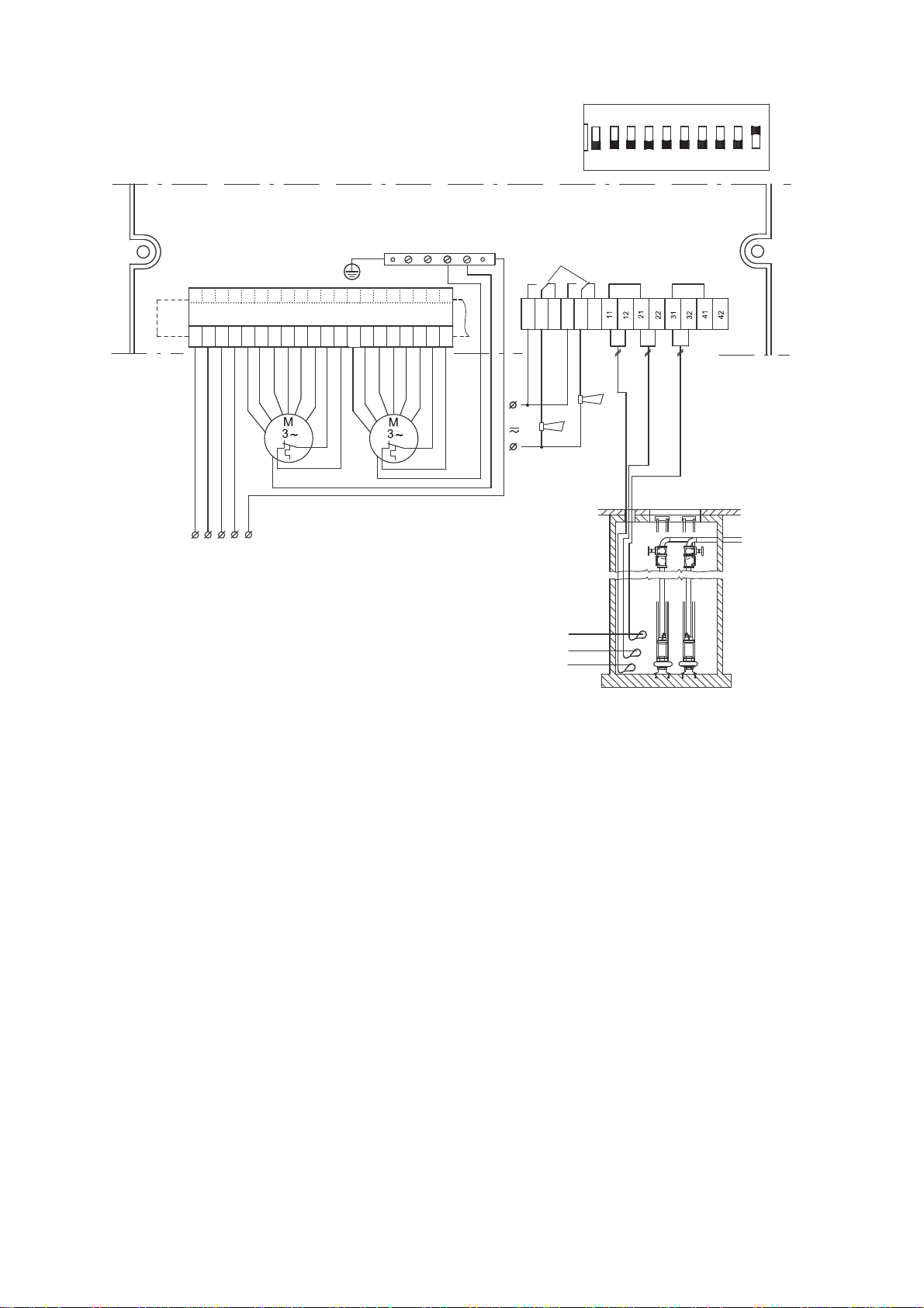
Fig. A2
ON DIP
12345678910
max. 230V
H-NO
max. 2A
H-NC
H-COM
G-NO
G-NC
G-COM
LCD 108
PE
V1
U1
N1
W1
1U2
1V2
1W2
2W2
2U2
2V2
T11
T21
3U2
3V2
3W2
4W2
4U2
4V2
T12
T22
Ext.
P1 P2
L1 L2 L3 N PE
3
2
1
TM01 8146 2308
24
Page 25

Fig. B1
1N2
1U2
2N2
2U2
T22
T12
T21
T11
N1
U1
L
11
P1 P2
1W2
1V2
1U2
2V2
2U2
2W2
L3L2L1
T22
T12
T21
T11
N1W1V1
U1
P1 P2
P1
P2
T11
T21
T12
T22
H-NO
max. 230V
max. 2A
H-NC
H-COM
G-NO
G-COM
G-NC
11
12
21
22
31
32
41
42
4
1-~ 3-~
TM01 6625 2308
TM04 0278 2308
TM04 0277 2308
25
Page 26

Fig. B2
P1 P2
W1
V1
U1
1U2
N1
2U2
1V2
2V2
T11
T21
T12
T22
3U2
3V2
3W2
4U2
4V2
4W2
1W2
2W2
4
3
2
1
max. 230V
max. 2A
H-NC
H-COM
H-NO
G-NC
G-COM
G-NO
L1 L2 L3 N PE
PE
LCD 108
TM01 8147 2308
26
Page 27

Fig. C1
1N2
1U2
2N2
2U2
T22
T12
T21
T11
N1
U1
L
11
P1 P2
1W2
1V2
1U2
2V2
2U2
2W2
L3L2L1
T22
T12
T21
T11
N1W1V1
U1
P1 P2
P1
P2
max. 230V
max. 2A
ON DIP
12345678910
11
12
21
22
31
32
41
T11
T21
T12
T22
H-NO
H-COM
H-NC
G-NO
G-COM
G-NC
42
LCD 108
Ext.
4
3
2
1
1-~ 3-~
TM01 8462 2308
TM04 0278 2308
TM04 0277 2308
27
Page 28

Fig. C2
W1
V1
U1
1U2
N1
2U2
1V2
2V2
T11
T21
T12
T22
3U2
3V2
3W2
4U2
4V2
4W2
1W2
2W2
P1 P2
L1 L2 L3 N PE
LCD 108
Ext.
4
3
2
1
ON DIP
12345678910
max. 230V
max. 2A
H-NO
H-COM
H-NC
G-NO
G-COM
G-NC
11
12212231324142
TM01 8598 2308
28
Page 29

Fig. D1
4
3
2
1
P1
P2
H-NO
T22
T12
T21
T11
H-COM
H-NC
G-NO
G-COM
G-NC
11
12
21
22
31
32
41
42
LCD 108
Ext.
ON DIP
12345678910
max. 230V
max. 2A
1N2
1U2
2N2
2U2
T22
T12
T21
T11
N1
U1
L
11
P1 P2
1W2
1V2
1U2
2V2
2U2
2W2
L3L2L1
T22
T12
T21
T11
N1W1V1
U1
P1 P2
TM01 8463 2308
1-~ 3-~
TM04 0278 2308
TM04 0277 2308
29
Page 30

Fig. D2
ON DIP
12345678910
max. 230V
max. 2A
H-NC
G-NO
G-NC
G-COM
LCD 108
H-NO
V1
U1
N1
W1
1U2
1V2
1W2
2W2
2U2
2V2
T11
T21
3U2
3V2
3W2
4W2
4U2
4V2
T12
T22
H-COM
P1 P1
L1 L2 L3 N PE
4
3
2
1
TM01 8464 2308
30
Page 31

Argentina
Bombas GRUNDFOS de Argentina S.A.
Ruta Panamericana km. 37.500 Lote 34A
1619 - Garin
Pcia. de Buenos Aires
Phone: +54-3327 414 444
Telefax: +54-3327 411 111
Australia
GRUNDFOS Pumps Pty. Ltd.
P.O. Box 2040
Regency Park
South Australia 5942
Phone: +61-8-8461-4611
Telefax: +61-8-8340 0155
Austria
GRUNDFOS Pumpen Vertrieb Ges.m.b.H.
Grundfosstraße 2
A-5082 Grödig/Salzburg
Tel.: +43-6246-883-0
Telefax: +43-6246-883-30
Belgium
N.V. GRUNDFOS Bellux S.A.
Boomsesteenweg 81-83
B-2630 Aartselaar
Tél.: +32-3-870 7300
Télécopie: +32-3-870 7301
Belorussia
Представительство ГРУНДФОС в
Минске
220123, Минск,
ул. В. Хоружей, 22, оф. 1105
Тел.: +(37517) 233 97 65,
Факс: +(37517) 233 97 69
E-mail: grundfos_minsk@mail.ru
Bosnia/Herzegovina
GRUNDFOS Sarajevo
Trg Heroja 16,
BiH-71000 Sarajevo
Phone: +387 33 713 290
Telefax: +387 33 659 079
e-mail: grundfos@bih.net.ba
Brazil
Mark GRUNDFOS Ltda.
Av. Humberto de Alencar Castelo Branco,
630
CEP 09850 - 300
São Bernardo do Campo - SP
Phone: +55-11 4393 5533
Telefax: +55-11 4343 5015
Bulgaria
GRUNDFOS Pumpen Vertrieb
Representative Office - Bulgaria
Bulgaria, 1421 Sofia
Lozenetz District
105-107 Arsenalski blvd.
Phone: +359 2963 3820, 2963 5653
Telefax: +359 2963 1305
Canada
GRUNDFOS Canada Inc.
2941 Brighton Road
Oakville, Ontario
L6H 6C9
Phone: +1-905 829 9533
Telefax: +1-905 829 9512
China
GRUNDFOS Pumps (Shanghai) Co. Ltd.
51 Floor, Raffles City
No. 268 Xi Zang Road. (M)
Shanghai 200001
PRC
Phone: +86-021-612 252 22
Telefax: +86-021-612 253 33
Croatia
GRUNDFOS CROATIA d.o.o.
Cebini 37, Buzin
HR-10010 Zagreb
Phone: +385 1 6595 400
Telefax: +385 1 6595 499
www.grundfos.hr
Czech Republic
GRUNDFOS s.r.o.
Čajkovského 21
779 00 Olomouc
Phone: +420-585-716 111
Telefax: +420-585-716 299
Denmark
GRUNDFOS DK A/S
Martin Bachs Vej 3
DK-8850 Bjerringbro
Tlf.: +45-87 50 50 50
Telefax: +45-87 50 51 51
E-mail: info_GDK@grundfos.com
www.grundfos.com/DK
Estonia
GRUNDFOS Pumps Eesti OÜ
Peterburi tee 92G
11415 Tallinn
Tel: + 372 606 1690
Fax: + 372 606 1691
Finland
OY GRUNDFOS Pumput AB
Mestarintie 11
FIN-01730 Vantaa
Phone: +358-3066 5650
Telefax: +358-3066 56550
France
Pompes GRUNDFOS Distribution S.A.
Parc d’Activités de Chesnes
57, rue de Malacombe
F-38290 St. Quentin Fallavier (Lyon)
Tél.: +33-4 74 82 15 15
Télécopie: +33-4 74 94 10 51
Germany
GRUNDFOS GMBH
Schlüterstr. 33
40699 Erkrath
Tel.: +49-(0) 211 929 69-0
Telefax: +49-(0) 211 929 69-3799
e-mail: infoservice@grundfos.de
Service in Deutschland:
e-mail: kundendienst@grundfos.de
Greece
GRUNDFOS Hellas A.E.B.E.
20th km. Athinon-Markopoulou Av.
P.O. B o x 7 1
GR-19002 Peania
Phone: +0030-210-66 83 400
Telefax: +0030-210-66 46 273
Hong Kong
GRUNDFOS Pumps (Hong Kong) Ltd.
Unit 1, Ground floor
Siu Wai Industrial Centre
29-33 Wing Hong Street &
68 King Lam Street, Cheung Sha Wan
Kowloon
Phone: +852-27861706 / 27861741
Telefax: +852-27858664
Hungary
GRUNDFOS Hungária Kft.
Park u. 8
H-2045 Törökbálint,
Phone: +36-23 511 110
Telefax: +36-23 511 111
India
GRUNDFOS Pumps India Private Limited
118 Old Mahabalipuram Road
Thoraipakkam
Chennai 600 096
Phone: +91-44 2496 6800
Indonesia
PT GRUNDFOS Pompa
Jl. Rawa Sumur III, Blok III / CC-1
Kawasan Industri, Pulogadung
Jakarta 13930
Phone: +62-21-460 6909
Telefax: +62-21-460 6910 / 460 6901
Ireland
GRUNDFOS (Ireland) Ltd.
Unit A, Merrywell Business Park
Ballymount Road Lower
Dublin 12
Phone: +353-1-4089 800
Telefax: +353-1-4089 830
Italy
GRUNDFOS Pompe Italia S.r.l.
Via Gran Sasso 4
I-20060 Truccazzano (Milano)
Tel.: +39-02-95838112
Telefax: +39-02-95309290 / 95838461
Japan
GRUNDFOS Pumps K.K.
Gotanda Metalion Bldg., 5F,
5-21-15, Higashi-gotanda
Shiagawa-ku, Tokyo
141-0022 Japan
Phone: +81 35 448 1391
Telefax: +81 35 448 9619
Korea
GRUNDFOS Pumps Korea Ltd.
6th Floor, Aju Building 679-5
Yeoksam-dong, Kangnam-ku, 135-916
Seoul, Korea
Phone: +82-2-5317 600
Telefax: +82-2-5633 725
Latvia
SIA GRUNDFOS Pumps Latvia
Deglava biznesa centrs
Augusta Deglava ielā 60, LV-1035, Rīga,
Tālr.: + 371 714 9640, 7 149 641
Fakss: + 371 914 9646
Lithuania
GRUNDFOS Pumps UAB
Smolensko g. 6
LT-03201 Vilnius
Tel: + 370 52 395 430
Fax: + 370 52 395 431
Malaysia
GRUNDFOS Pumps Sdn. Bhd.
7 Jalan Peguam U1/25
Glenmarie Industrial Park
40150 Shah Alam
Selangor
Phone: +60-3-5569 2922
Telefax: +60-3-5569 2866
México
Bombas GRUNDFOS de México S.A. de
C.V.
Boulevard TLC No. 15
Parque Industrial Stiva Aeropuerto
Apodaca, N.L. 66600
Phone: +52-81-8144 4000
Telefax: +52-81-8144 4010
Netherlands
GRUNDFOS Netherlands
Velu we zo om 35
1326 AE Almere
Postbus 22015
1302 CA ALMERE
Tel.: +31-88-478 6336
Telefax: +31-88-478 6332
e-mail: info_gnl@grundfos.com
New Zealand
GRUNDFOS Pumps NZ Ltd.
17 Beatrice Tinsley Crescent
North Harbour Industrial Estate
Albany, Auckland
Phone: +64-9-415 3240
Telefax: +64-9-415 3250
Norway
GRUNDFOS Pumper A/S
Strømsveien 344
Postboks 235, Leirdal
N-1011 Oslo
Tlf.: +47-22 90 47 00
Telefax: +47-22 32 21 50
Poland
GRUNDFOS Pompy Sp. z o.o.
ul. Klonowa 23
Baranowo k. Poznania
PL-62-081 Przeźmierowo
Tel: (+48-61) 650 13 00
Fax: (+48-61) 650 13 50
Portugal
Bombas GRUNDFOS Portugal, S.A.
Rua Calvet de Magalhães, 241
Apartado 1079
P-2770-153 Paço de Arcos
Tel.: +351-21-440 76 00
Telefax: +351-21-440 76 90
România
GRUNDFOS Pompe România SRL
Bd. Biruintei, nr 103
Pantelimon county Ilfov
Phone: +40 21 200 4100
Telefax: +40 21 200 4101
E-mail: romania@grundfos.ro
Russia
ООО Грундф ос
Россия, 109544 Москва, ул. Школьная
39
Тел. (+7) 495 737 30 00, 564 88 00
Факс (+7) 495 737 75 36, 564 88 11
E-mail grundfos.moscow@grundfos.com
Serbia
GRUNDFOS Predstavništvo Beograd
Dr. Milutina Ivkovića 2a/29
YU-11000 Beograd
Phone: +381 11 26 47 877 / 11 26 47 496
Telefax: +381 11 26 48 340
Singapore
GRUNDFOS (Singapore) Pte. Ltd.
24 Tuas West Road
Jurong Town
Singapore 638381
Phone: +65-6865 1222
Telefax: +65-6861 8402
Slovenia
GRUNDFOS PUMPEN VERTRIEB
Ges.m.b.H.,
Podružnica Ljubljana
Šlandrova 8b, SI-1231 Ljubljana-Črnuče
Phone: +386 1 568 0610
Telefax: +386 1 568 0619
E-mail: slovenia@grundfos.si
Spain
Bombas GRUNDFOS España S.A.
Camino de la Fuentecilla, s/n
E-28110 Algete (Madrid)
Tel.: +34-91-848 8800
Telefax: +34-91-628 0465
Sweden
GRUNDFOS AB
Box 333 (Lunnagårdsgatan 6)
431 24 Mölndal
Tel.: +46(0)771-32 23 00
Telefax: +46(0)31-331 94 60
Switzerland
GRUNDFOS Pumpen AG
Bruggacherstrasse 10
CH-8117 Fällanden/ZH
Tel.: +41-1-806 8111
Telefax: +41-1-806 8115
Taiwan
GRUNDFOS Pumps (Taiwan) Ltd.
7 Floor, 219 Min-Chuan Road
Taichung, Taiwan, R.O.C.
Phone: +886-4-2305 0868
Telefax: +886-4-2305 0878
Thailand
GRUNDFOS (Thailand) Ltd.
92 Chaloem Phrakiat Rama 9 Road,
Dokmai, Pravej, Bangkok 10250
Phone: +66-2-725 8999
Telefax: +66-2-725 8998
Turkey
GRUNDFOS POMPA San. ve Tic. Ltd. Sti.
Gebze Organize Sanayi Bölgesi
Ihsan dede Caddesi,
2. yol 200. Sokak No. 204
41490 Gebze/ Kocaeli
Phone: +90 - 262-679 7979
Telefax: +90 - 262-679 7905
E-mail: satis@grundfos.com
Ukraine
ТОВ ГРУНДФОС УКРАЇНА
01010 Київ, Вул. Московська 8б,
Тел.:(+38 044) 390 40 50
Фах.: (+38 044) 390 40 59
E-mail: ukraine@grundfos.com
United Arab Emirates
GRUNDFOS Gulf Distribution
P.O. Box 16768
Jebel Ali Free Zone
Dubai
Phone: +971-4- 8815 166
Telefax: +971-4-8815 136
United Kingdom
GRUNDFOS Pumps Ltd.
Grovebury Road
Leighton Buzzard/Beds. LU7 8TL
Phone: +44-1525-850000
Telefax: +44-1525-850011
U.S.A.
GRUNDFOS Pumps Corporation
17100 West 118th Terrace
Olathe, Kansas 66061
Phone: +1-913-227-3400
Telefax: +1-913-227-3500
Usbekistan
Представительство ГРУНДФОС в
Ташкенте
700000 Ташк ент ул.Ус ма на Носира 1-й
тупик 5
Телефон : (3712) 55-68-15
Факс: (3712) 53-36-35
Addresses revised 15.06.2009
Page 32

Being responsible is our foundation
Thinking ahead makes it possible
Innovation is the essence
97502178 0609
www.grundfos.com
GB
 Loading...