

Page 1
English (GB) Installation and operating instructions
Caution
Note
Note
Original installation and operating instructions.
CONTENTS
Page
1. Symbols used in this document
2. Applications
3. System sizing
4. Electrical connection
5. Ejector valve
5.1 Ejector valve setting
6. Start-up
6.1 Shaft seal run-in
7. Adjustment
7.1 Calculating the cut-in and cut-out
pressures
7.2 Adjusting the precharge pressure
7.3 Setting the pressure switch
8. Operation and maintenance
9. Frost protection
10. Technical data
11. Fault finding
12. Disposal
Warning
Prior to installation, read this document
and the quick guide. Installation and
operation must comply with local
regulations and accepted codes of
good practice.
Warning
The use of this product requires
experience with and knowledge of the
product.
Persons with reduced physical,
sensory or mental capabilities must not
use this product, unless they are under
supervision or have been instructed in
the use of the product by a person
responsible for their safety.
Children must not use or play with this
product.
1. Symbols used in this document
Warning
If these safety instructions are not
observed, it may result in personal
injury.
Warning
If these instructions are not observed,
it may lead to electric shock with
consequent risk of serious personal
injury or death.
If these safety instructions are not
observed, it may result in malfunction
or damage to the equipment.
9
9
9
2. Applications
9
The JP Booster PT is suitable for pressure boosting
of fresh water in domestic water supply systems.
10
10
3. System sizing
10
10
11
11
11
11
12
12
4. Electrical connection
12
13
13
Check that the supply voltage and frequency
correspond to the values stated on the nameplate.
Single-phase motors incorporate a thermal switch
and require no additional motor protection.
Three-phase motors must be connected to an
external mains switch and a motor-protective circuit
breaker.
Notes or instructions that make the job
easier and ensure safe operation.
Warning
The system in which the product is
incorporated must be designed for the
maximum pump pressure.
The default setting can be found in the
quick guide.
Warning
The electrical installation should be
carried out by an authorised person in
accordance with local regulations.
Warning
During electrical installation, make sure
that the power supply cannot be
accidentally switched on.
Warning
The unit must be connected to an
external mains switch with a minimum
contact gap of 3 mm in all poles.
As a precaution, the pump must be
connected to a socket with earth
connection.
We recommend to fit the permanent
installation with an earth leakage circuit
breaker (ELCB) with a tripping current
≤
30 mA.
English (GB)
9
Page 2
5. Ejector valve
Note
V
S
P
T
0.0 0.5 1.0 1.5 2.0 2.5 3.0 3.5 4.0 Q [m³/h]
0
5
10
15
20
25
30
35
40
45
H
[m]
0.00 0. 25 0.50 0.75 1.00 Q [l/s]
JP 5
IS O 9906 Annex A
P
o
s
.
1
P
o
s
.
2
Caution
Note
English (GB)
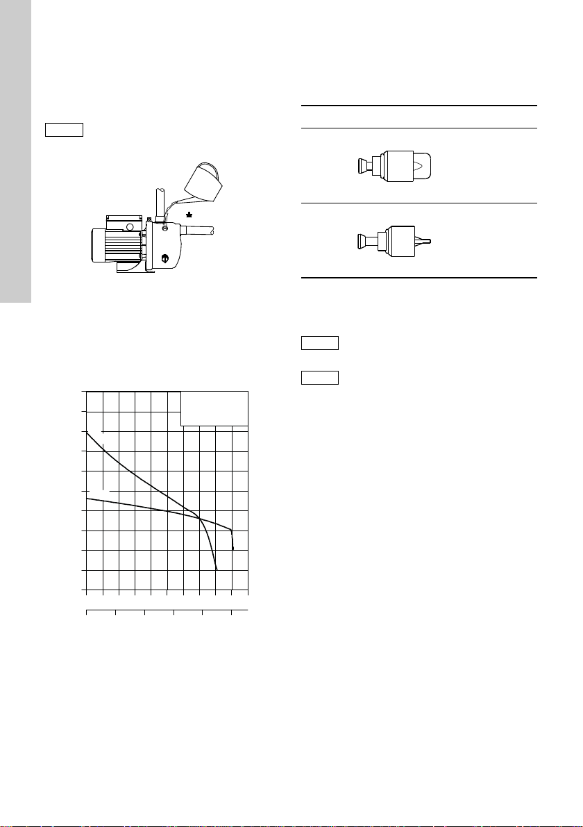
The ejector valve is supplied separate with the
pump.
Remove the plug (V), see fig. 1, and fit the ejector
valve into the hole.
The O-ring must be fitted to the ejector
valve.
Tighten the valve using fingers only.
Pos. 2
Turn the valve to the right (in).
Select pos. 2 when the pump has been primed, and
a large quantity of water and a low pressure are
required.
Pos. Ejector valve Direction
1
Left
(out)
TM04 2299 2308
Fig. 1 Ejector valve
5.1 Ejector valve setting
The ejector valve in the plug hole (V) can be turned
to two positions. See fig. 3.
Figure 2 shows an example of how the ejector valve
position may affect the QH curve.
Fig. 2 QH curve and ejector valve positions
Pos. 1
Turn the valve to the left (out).
Select pos. 1 when the suction pipe is empty and the
pump is to be primed.
Select also pos. 1 when a small quantity of water and
a high pressure are required.
10
2
TM00 5495 4995TM00 7474 1396
Right
(in)
Fig. 3 Ejector valve positions
6. Start-up
Do not start the pump until it has been
filled with liquid. See the quick guide.
We recommend to fit a non-return valve
on the suction side of the pump.
6.1 Shaft seal run-in
The seal faces are lubricated by the pumped liquid,
meaning that there may be a certain amount of
leakage from the shaft seal.
When the pump is started up for the first time, or
when a new shaft seal is installed, a certain run-in
period is required before the leakage is reduced to
an acceptable level. The time required for this
depends on the operating conditions, i.e. every time
the operating conditions change, a new run-in period
will be started.
Under normal conditions, the leaking liquid will
evaporate. As a result, no leakage will be detected.
TM04 2300 2308
Page 3
7. Adjustment
Note
Caution
Note
The JP Booster PT comes with the following factory
settings in bar:
Pump
JP 5 & 6 1.9 2.2 3.3
Tank
precharge
pressure
7.1 Calculating the cut-in and cut-out pressures
The cut-in pressure is the sum of these variables:
• required minimum pressure at the highest
tapping point
from the pump to the highest tapping point
• head
• pressure loss in pipes.
Recommended cut-out pressure:
cut-in pressure + 1.0 - 1.5 bar.
The cut-out pressure must not exceed
the maximum discharge pressure of the
pump.
7.2 Adjusting the precharge pressure
When the pump cut-in pressure has been
determined, the required precharge pressure of the
diaphragm tank can be calculated. The precharge
pressure must be adjusted to 90 % of the cut-in
pressure.
When adjusting/reading the precharge
pressure, make that there is no water
pressure on the diaphragm tank from
the pipework.
If the pressure switch setting is
changed, the precharge pressure must
be adjusted too.
See the installation and operating instructions for the
diaphragm tank.
Cut-in
pressure
Cut-out
pressure
7.3 Setting the pressure switch
Warning
Switch off the power supply before
adjusting the pressure switch.
Fit the cover on the pressure switch
before you switch on the power supply
to check the cut-in and cut-out
pressure.
The cut-out pressure must be lower than the
maximum operating pressure of the pump and tank.
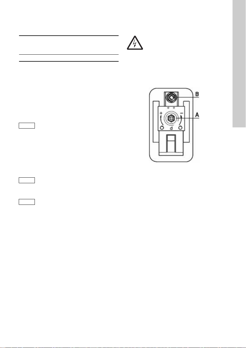
Remove the cover from the pressure switch to
access the adjusting screws. See fig. 4.
Fig. 4 Pressure switch
Setting the cut-out pressure
1. Turn screw (pos. A) clockwise to increase the
cut-out pressure.
Turn it counter-clockwise to reduce the cut-out
pressure.
The differential pressure range remains
unchanged.
2. Start the pump and check by reading the
pressure gauge whether the desired cut-out and
cut-in pressures have been obtained.
Setting the cut-in pressure
1. Turn screw (pos. B) clockwise to reduce the
cut-in pressure.
Turn it counter-clockwise to increase the cut-in
pressure.
The differential pressure range is widened and
narrowed respectively.
2. Start the pump and check by reading the
pressure gauge whether the desired cut-out and
cut-in pressures have been obtained.
Repeat the procedure until the right cut-in and
cut-out pressures have been obtained.
English (GB)
TM01 6914 3799
11
Page 4

8. Operation and maintenance
Caution
English (GB)
Warning
Prior to start-up, the system should be
flushed through with clean water and
drained to remove possible impurities.
Do not cover the motor of the booster
system as an adequate supply of cool
air must reach the motor cooling fan.
9. Frost protection
If there is a risk of frost, the tank and pump must be
drained.
10. Technical data
Ambient temperature
Maximum +40 °C.
Storage temperature
Minimum -20 °C.
Maximum +70 °C.
Liquid temperature
+40 °C.
System pressure
Maximum 6 bar.
Inlet pressure
At inlet pressures above 1.5 bar the discharge
pressure must be at least 2.5 bar.
Supply voltage
1 x 220-240 V, 50 Hz.
3 x 220-240/380-415 V, 50 Hz.
Insulation class
F.
Enclosure class
IP44.
Relative air humidity
Maximum 95 %.
Sound power level
The sound power level of the pump is lower than
72 dB(A).
Start/stop frequency
Maximum 100 per hour.
12
Page 5

11. Fault finding
Warning
Before starting fault finding, switch off
the power supply. Make sure that the
power supply cannot be accidentally
switched on.
Fault Cause Remedy
1. The pump does
not start.
2. There is power on
the pressure
switch but not the
pump.
3. The pump does
not start when
water is
consumed.
4. Frequent
starts/stops.
5. The pump does
not stop.
6. The motor cuts
out during
operation.
* Or contact the nearest Grundfos company or
service workshop.
a) The fuses in the electric
installation have burnt.
b) The earth leakage circuit
breaker or the
voltage-operated circuit
breaker has tripped.
a) The power supply to the pump
is disconnected after the
pressure switch unit.
b) The pressure switch unit is
defective.
a) Too big difference in height
between the pressure switch
unit and the tapping point.
b) The pressure switch unit is
defective.
a) Leakage in the pipework. Check and repair the pipework.
b) The pressure tank has no
precharge pressure, or the
tank size is insufficient.
a) The pressure switch unit is
defective.
a) The thermal switch in the
motor has tripped due to
overheating.
Replace the fuses. If the new fuses also burn,
check the electric installation.
Cut in the circuit breaker and check the electric
installation.
Check the cable connections.
Repair or replace the pressure switch unit. *
Adjust the cut-in pressure.
Repair or replace the pressure switch unit. *
Check the tank precharge pressure, and
recharge the tank, if necessary. See section 7.
Repair or replace the pressure switch unit. *
The thermal switch will cut in automatically
when the motor has cooled sufficiently.
If the problem still persists, check these two
possible causes:
• Impeller stuck.
Clean the pump.
• Motor defective.
Repair or replace the motor. *
English (GB)
12. Disposal
This product or parts of it must be disposed of in an
environmentally sound way:
1. Use the public or private waste collection service.
2. If this is not possible, contact the nearest
Grundfos company or service workshop.
Subject to alterations.
13
 Loading...