

Page 1

Hydro Multi-E
Installation and operating instructions
GRUNDFOS INSTRUCTIONS
Page 2

English (GB) Installation and operating instructions
English (GB)
Original installation and operating instructions
These installation and operation instructions apply to the
Grundfos Hydro Multi-E booster systems.
CONTENTS
1. Symbols used in this document
1.1 Warnings against hazards involving risk of death or
personal injury
1.2 Other important notes
2. Scope of these instructions
3. System sizing
4. Product description
4.1 General description
4.2 Functions
4.3 Hydro Multi-E
5. Identification
5.1 Nameplate
6. Type key
7. Operating conditions
7.1 Temperatures
7.2 Installation altitude
7.3 Relative humidity
7.4 Maximum operating pressure
7.5 Shaft seal run-in
7.6 Minimum inlet pressure
7.7 Maximum inlet pressure
7.8 Minimum flow rate
7.9 Start and stop
7.10 Diaphragm tank
8. Installation
8.1 Location
8.2 Mechanical installation
8.3 Electrical installation
8.4 Mains supply
8.5 Additional protection
9. Startup
9.1 Hydro Multi-E in system with positive inlet pressure
9.2 Hydro Multi-E in system without inlet pressure
10. Operating modes
10.1 Normal operation
10.2 Stop or Max. operation
10.3 Operating condition in case of disconnection of power
supply
10.4 Further settings
11. User interfaces
11.1 Standard control panel
12. Grundfos GO Remote
12.1 Communication
12.2 Menu overview for Grundfos GO Remote
13. Multi-master function
13.1 Systems with one outlet-pressure sensor
13.2 Systems with two or more outlet-pressure sensors
14. Protective functions
14.1 Dry-running protection
15. Bus signal
16. Priority of settings
17. Grundfos Eye
18. Signal relays
19. Digital input
20. Data communication
21. Insulation resistance
22. Maintenance
22.1 Pumps
22.2 Motors
22.3 Breaker cabinet
Page
10
10
10
10
10
10
10
12
12
13
14
14
14
14
14
16
16
17
18
19
19
19
19
19
19
19
23. Shutdown
23.1 Frost protection
23.2 Service kits
24. Fault finding
25. Technical data, Hydro Multi-E with single-phase
pumps
2
2
2
3
3
3
3
3
3
3
3
4
5
5
5
5
5
5
5
6
6
6
6
6
6
6
7
7
8
8
8
9
25.1 Supply voltage
25.2 Leakage current
26. Technical data, Hydro Multi-E with three-phase
pumps
26.1 Supply voltage
26.2 Leakage current
27. Inputs and outputs
28. Other technical data
29. Sound pressure level
29.1 Hydro Multi-E with single-phase pumps
29.2 Hydro Multi-E with three-phase pumps
30. Disposal
Prior to installation, read this document. Installation
and operation must comply with local regulations and
accepted codes of good practice.
1. Symbols used in this document
1.1 Warnings against hazards involving risk of death or personal injury
DANGER
Indicates a hazardous situation which, if not avoided,
will result in death or serious personal injury.
WARNING
Indicates a hazardous situation which, if not avoided,
could result in death or serious personal injury.
CAUTION
Indicates a hazardous situation which, if not avoided,
could result in minor or moderate personal injury.
The text accompanying the three hazard symbols DANGER,
WARNING and CAUTION is structured in the following way:
SIGNAL WORD
Description of hazard
Consequence of ignoring the warning.
- Action to avoid the hazard.
1.2 Other important notes
A blue or grey circle with a white graphical symbol
indicates that an action must be taken.
A red or grey circle with a diagonal bar, possibly with
a black graphical symbol, indicates that an action
must not be taken or must be stopped.
If these instructions are not observed, it may result in
malfunction or damage to the equipment.
19
19
19
20
21
21
21
21
21
21
21
22
22
22
22
22
2
Page 3

Tips and advice that make the work easier.
Pump
Non-return
valve
Outlet-pressure
sensor
Pressure
gauge
Isolating
valve
Diaphragm tank
Breaker cabinet
Pressure
switch
MADE IN GERMANY
DK - 8850 - Bjerringbro - Denmark
QR
code
IP Class: IP54
Weight: 83kg
Liq. temp.: 5-60ºC
pMax: 16 bar
Q Nom / Max: 14 / 20 m /h
H Nom / Max: 68 / 93 m
3
Mains supply: 3 x 380 - 415
Serial No.: -
Model: 98486745
Type: Hydro Multi-E 2 CRIE 5-9 U2 A-A-A-A
1
2
3
4
5
6
7
8
9
10
11
12
13
14
15
4.3 Hydro Multi-E
2. Scope of these instructions
These installation and operating instructions apply to the
Grundfos Hydro Multi-E booster systems.
Hydro Multi-E is a range of factory-assembled booster systems,
ready for installation and operation.
3. System sizing
The system in which Hydro Multi-E is incorporated
must be designed for the maximum pump pressure.
4. Product description
4.1 General description
The Grundfos Hydro Multi-E booster systems are designed for
pressure boosting of clean water in blocks of flats, hotels,
hospitals, schools, etc.
Hydro Multi-E incorporates Grundfos CRE, CRIE, CME-A or
CME-I pumps with integrated frequency-controlled single- or
three-phase MGE motors and a breaker cabinet.
The system maintains a constant pressure through continuous
variable adjustment of the speed of the pumps connected.
The system adjusts its performance to the demand by cutting the
required number of pumps in or out and by parallel control of the
pumps in operation.
The system has been factory-assembled and tested with the
control parameters mentioned in the quick guide supplied with the
booster system.
English (GB)
TM02 4280 1902TM06 7460 3516
Fig. 1 Hydro Multi-E components
The breaker cabinet incorporates a main switch and circuit
breakers.
5. Identification
5.1 Nameplate
4.2 Functions
Hydro Multi-E offers the following functions:
• multi-master function
• constant pressure
• redundant sensor
• stop at low flow
• cascade control of pumps
• automatic alternation
• pipe filling
• limit-exceeded function
• two digital inputs
• two digital outputs
• two analog inputs
• optional bus communication via Grundfos CIM modules.
Fig. 2 Hydro Multi-E nameplate
Pos. Description
1 Type designation
2 Model
3 Serial number
4 Supply voltage
5 Maximum operating pressure in bar
6 Liquid temperature
7 Enclosure class
8 Weight in kg
9 Country of origin
10 Company logo
3
11 Maximum flow rate in m
12 Nominal head in metres
13 Approval mark
/h
14 Approval mark
15 QR code
3
Page 4

6. Type key
English (GB)
Example
Name
System type
E: All pumps with E-motor
Number of main pumps
Pump type
Voltage code
U1: 3 x 380-415, N, PE, 50/60 Hz (three phase system with single-phase pumps)
U2: 3 x 380-415, PE, 50/60 Hz
U7: 1 x 200-240, PE, 50/60 Hz
U8: 1 x 200-240, N, PE, 50/60 Hz
UX: CSU variant (special voltage rating)
Design
A: Systems with breaker cabinet mounted on the system
B: Systems with wall mounted breaker cabinet and 5 m power supply cable
C: Systems with breaker cabinet mounted on the left side.
Starting method
A: E, variable frequency, VFD
Material combination
A: Stainless steel manifold, base frame and standard valves
B: Stainless steel manifold, base frame and valves
C: Galvanised steel manifold, base frame and standard valves (CME-A pumps only)
G: Galvanised steel manifold, base frame and standard valves
P: Stainless steel manifold, galvanised steel base frame and standard valves
Hydro Multi -E 2 CRIE 15-3 U7 A- A- A- A- ABCDEF
Drinking water approvals
A: ACS-approved components
B: Belgaqua-approved components
D: DVGW-approved components
K: KIWA-approved components
N: NFS-approved components
V: WRAS-approved components
W: WRAS-approved system
Y: No special approval
Options
A: Standard hydraulics
B: No redundant outlet-pressure sensor
C: Outlet-pressure sensor on each pump
D: Sensor as dry-running protection
E: No dry-running protection
F: Level switch as dry-running protection
G: CIM module included
K: No inlet manifold
L: Non-return valves on the inlet side
S: CSU variant
U: Undersized motor
X: More than four options
4
Page 5

7. Operating conditions
1
0.99
0.98
0.97
0.96
0.95
0.94
0.93
0.92
0.91
0.90
0.89
0.88
0
0
1000 1200 1400 1600 1800 2000 2200
[m]
P2
[%]
Altitude [m]
P2
[%]
Hv
H
NPSH
Pb
Hf
Hf
H
pb
Hv
NPSH
7.1 Temperatures
7.1.1 Ambient temperature during storage and transportation
Minimum -30 °C
Maximum +60 °C.
7.1.2 Ambient temperature during operation
Minimum -20 °C
Maximum +50 °C.
The motors can operate with the rated output power (P2) at 50
°C, but continuous operation at higher temperatures will reduce
the expected product life. If the motors are to operate at ambient
temperatures between 50 and 60 °C, oversized motors must be
selected. Contact Grundfos for further information.
7.1.3 Liquid temperature
0 to +60 °C.
7.2 Installation altitude
Do not install the motors more than 2000 metres
above sea level.
Installation altitude is the height above sea level of the installation
site.
• Motors installed up to 1000 metres above sea level can be
loaded 100 %.
• Motors installed more than 1000 metres above sea level must
not be fully loaded due to the low density and consequent low
cooling effect of the air. See fig. 3.
7.3 Relative humidity
Maximum 95 %.
7.4 Maximum operating pressure
See system nameplate.
7.5 Shaft seal run-in
The seal faces are lubricated by the pumped liquid, meaning that
there may be a certain amount of leakage from the shaft seal.
When the pump is started up for the first time, or when a new
shaft seal is installed, a certain run-in period is required before
the leakage is reduced to an acceptable level. The time required
for this depends on the operating conditions, that is every time
the operating conditions change, a new run-in period will be
started.
Under normal conditions, the leaking liquid evaporates. As a
result, a leakage will not be detected.
7.6 Minimum inlet pressure
Fig. 4 Parameters for the calculation of minimum inlet
pressure
English (GB)
TM02 0118 3800
The minimum inlet pressure "H" in metres head required to avoid
cavitation in the pumps can be calculated as follows:
Hydro Multi-E with CME pumps
H = pb x 10.2 - NPSH - Hf - Hv - Hs
pb = Barometric pressure in bar. Barometric pressure can
be set to 1 bar.
In closed systems, p
bar.
NPSH = Net Positive Suction Head in metres head
The NPSH value can be read from the NPSH curve at
the highest flow which the individual pump will be
delivering.
Hf = Friction loss in inlet manifold in metres head at the
TM05 6400 4712
Fig. 3 Derating of motor output power (P2) in relation to
altitude above sea level
Hv = Vapour pressure in metres head.
Hs = Safety margin of min. 0.5 metres head.
Hydro Multi-E systems with CME pumps always require a positive
inlet pressure, both during startup and operation.
highest flow the individual pump will be delivering.
Note: If a non-return valve is installed on the inlet side
of the pump, the friction loss in the valve must be
added. See the manufacturer's data.
In some regions, the booster system is available with
a low inlet manifold which makes it more suitable for
suction lift operation. Contact Grundfos for further
information.
indicates the system pressure in
b
5
Page 6

Example
2
2
11
2
English (GB)
pb = 1 bar.
Pump type = CRE 15, 50 Hz.
Flow rate = 15 m
NPSH
(from page 23) = 1.2 metres head.
Hf = 3.0 metres head.
Liquid
temperature = +60 °C.
Hv
(from page 24) = 2.1 metres head.
H = pb x 10.2 - NPSH - Hf - Hv - Hs [metres head].
H = 1 x 10.2 - 1.2 - 3.0 - 2.1 - 0.5 equal to 2.8
This means that each pump can operate at a suction lift of
maximum 2.8 metres head.
Pressure calculated in bar: 2.8 x 0.0981 equal to 0.27.
Pressure calculated in kPa: 2.8 x 9.81 equal to 27.4.
3
/h
metres head.
7.7 Maximum inlet pressure
The maximum inlet pressure must not exceed 8 bar. However, the
actual inlet pressure plus pressure when the pump is operating
against a closed valve must always be lower than the maximum
operating pressure.
7.8 Minimum flow rate
Due to the risk of overheating, the pumps should not be used at
flow rates below 10 % of the rated flow rate of one pump.
The pumps must not run against a closed outlet
valve.
8. Installation
8.1 Location
Observe the following to ensure adequate cooling of motor and
electronics:
• Position Hydro Multi-E in such a way that adequate cooling is
ensured.
• Keep motor cooling fins and fan blades clean.
Hydro Multi-E is not suitable for outdoor installation.
The booster system must have a 1-metre clearance in front and
on the two sides.
8.2 Mechanical installation
Arrows on the pump base show the direction of flow of water
through the pump.
The pipes connected to the booster system must be of adequate
size. Fit expansion joints in the inlet and outlet pipes to avoid
resonance. See fig. 5.
Connect the pipes to the manifolds of the booster system.
The manifold comes with a screw cap fitted to one end. If this end
is to be used, remove the screw cap, apply sealing compound to
the other end of the manifold, and fit the screw. Fit a blanking
flange with gasket on flanged manifolds.
Tighten up the booster system prior to startup.
If booster systems are installed in blocks of flats or the first
consumer on the line is close to the booster system, we
recommend that you fit pipe hangers on the inlet and outlet pipes
to prevent vibration being transmitted through the pipes. See fig.
5.
Position the booster system on a plane and solid surface, for
example a concrete floor or foundation. If the booster system is
not fitted with vibration dampers, it must be bolted to the floor or
the foundation.
Fasten the pipes to parts of the building to ensure that they
cannot move or be twisted.
7.9 Start and stop
The system must not be started and stopped via the power supply
more than four times per hour.
When the system is switched on via the power supply, it will start
after approx. 5 seconds.
7.10 Diaphragm tank
The diaphragm tank precharge pressure must be set to 0.7 x
setpoint.
If the setpoint is changed, the diaphragm tank precharge
pressure should be changed accordingly to ensure optimum
operation.
Measure the precharge pressure while the system is
pressureless.
We recommend that you use nitrogen gas for precharging.
TM00 7748 1996
Fig. 5 Installation example with expansion joints and pipe
supports
Pos. Description
1 Expansion joint
2 Pipe supports
The expansion joints and pipe supports shown in fig. 5 are not
included in the standard booster system.
6
Page 7

8.3 Electrical installation
ELCB
(GFCI)
Breaker cabinet
Installation in building
ELCB
(GFCI)
Breaker cabinetInstallation in building
Carry out the electrical connection according to local regulations.
Check that the supply voltage and frequency correspond to the
values stated on the nameplate.
DANGER
Electric shock
Death or serious personal injury
- Switch off the power supply and wait at least five
minutes before you make any connections in the
breaker cabinet or terminal boxes. Make sure that
the power supply cannot be accidentally switched
on.
- Connect the motor to protective earth and protect
against indirect contact according to local
regulations.
If the power supply cable is damaged, it must be replaced by the
manufacturer, the manufacturer's service partner or a similarly
qualified person.
The user or the installer is responsible for the installation of
correct earthing and protection according to local regulations. All
operations must be carried out by a qualified electrician.
The booster system must be stationary and installed permanently.
Furthermore, connect the booster system permanently to the
power supply.
Carry out the earth connection as duplicate conductors.
If the system cannot be installed with the supply disconnecting
device located minimum 0.6 m above service level according to
EN 60204-1 paragraph 5.3.4, install the system with an external
"supply disconnecting device" made according to EN 60204-1,
paragraph 5.3.2. The system must be provided with a means
permitting it to be locked in OFF (isolated) position.
8.3.1 Protection against electric shock, indirect contact
8.4 Mains supply
Check that the supply voltage and frequency correspond to the
values stated on the nameplate.
Use dedicated IT network motors if the booster
system is supplied through an IT network. Contact
Grundfos.
The wires in the breaker cabinet must be as short as possible.
Excepted from this is the separated earth conductor which must
be so long that it is the last one to be disconnected in case the
cable is inadvertently pulled out of the cable entry.
For maximum backup fuse, see section 25.1 Supply voltage.
Fig. 6 Example of a mains-connected Hydro Multi-E with
backup fuses and additional protection (applies only
for systems with single-phase motors)
For maximum backup fuse, see section 26.1 Supply voltage.
English (GB)
TM02 4547 4211TM02 4546 4211
WARNING
Electric shock
Death or serious personal injury
- Connect the motor to protective earth and protect
against indirect contact according to local
regulations.
Protective-earth conductors must always have a yellow and
green (PE) or yellow, green and blue (PEN) colour marking.
Protection against mains voltage transients
The motor is protected against mains voltage transients in
accordance with EN 61800-3.
Motor protection
The motor requires no external motor protection. The motor
incorporates thermal protection against slow overloading and
blocking.
Fig. 7 Example of a mains-connected Hydro Multi-E with
backup fuses and additional protection (applies only
for systems with three-phase motors)
7
Page 8

8.5 Additional protection
ELCB
(GFCI)
ELCB
(GFCI)
Vent screws
English (GB)
8.5.1 Systems with single-phase motors
If Hydro Multi-E is connected to an electric installation where an
earth leakage circuit breaker (ELCB) or ground fault circuit
interrupter (GFCI) is used as additional protection, this circuit
breaker or interrupter must be marked with the following symbol:
When an earth leakage circuit breaker or ground
fault circuit interrupter is selected, the total leakage
current of all the electrical equipment in the
installation must be taken into account.
The leakage current of Hydro Multi-E can be found in section
25.2 Leakage current.
8.5.2 Systems with three-phase motors
If Hydro Multi-E is connected to an electric installation where an
earth leakage circuit breaker (ELCB) or ground fault circuit
interrupter (GFCI) is used as additional protection, this circuit
breaker or interrupter must be of the following type:
• It must be suitable for handling leakage currents and cutting-in
with short pulse-shaped leakage.
• It must trip when alternating fault currents and fault currents
with DC content, i.e. pulsating DC and smooth DC fault
currents, occur.
For these systems an earth leakage circuit breaker or ground
fault circuit interrupter, type B, must be used.
This circuit breaker or interrupter must be marked with the
following symbols:
9. Startup
Do not start the pumps until they have been filled
with liquid.
9.1 Hydro Multi-E in system with positive inlet pressure
When you have carried out the mechanical and electrical
installation described in section 8. Installation, proceed as
follows:
1. Check that Hydro Multi-E corresponds to order and that no
single parts have been damaged.
2. Switch off the power supply with the main switch.
3. Switch off the circuit breakers of all pumps.
4. Check that the precharge pressure in the diaphragm tank is
0.7 times the required outlet pressure (setpoint).
Measure the precharge pressure while the system is
pressureless.
5. Connect water and power supplies to the system.
6. Open all pump inlet and outlet valves.
7. Vent all pumps by means of the vent screws.
When an earth leakage circuit breaker or ground
fault circuit interrupter is selected, the total leakage
current of all the electrical equipment in the
installation must be taken into account.
The leakage current of Hydro Multi-E can be found in section
26.2 Leakage current.
Protection against phase unbalance
The motors must be connected to a power supply with a quality
corresponding to IEC 60146-1-1, class C, to ensure correct motor
operation at phase unbalance.
This also ensures long life of the components.
TM05 2008 4211
Fig. 8 Position of vent screws in systems with CME-A/-I
pumps
8
Page 9

English (GB)
Vent screws
Vent screw
Filling screw
Fig. 9 Position of vent screws in systems with CR(I)E pumps
8. Switch on the power supply with the main switch.
9. Start pump 1 by pressing the start/stop button on the pump
control panel.
10. Vent pump 1 by means of the vent screw.
11. Repeat steps 9 and 10 for the other pumps in the system.
12. Set the desired outlet pressure.
If you change the outlet pressure, change the
diaphragm tank precharge pressure accordingly.
13. Check that the pumps are cutting in and out, thus adjusting
the performance to the demand.
Hydro Multi-E is now in automatic mode and ready for operation.
9.2 Hydro Multi-E in system without inlet pressure
Hydro Multi-E systems with CME pumps require a
positive inlet pressure during startup and operation.
The following startup procedure therefore only
applies to Hydro Multi-E systems with CRE or CRIE
pumps.
When you have carried out the mechanical and electrical
installation described in section 8. Installation, proceed as
follows:
1. Check that Hydro Multi-E corresponds to order and that no
single parts have been damaged.
2. Switch off the power supply with the main switch.
3. Switch off the circuit breakers of all pumps.
4. Check that the precharge pressure in the diaphragm tank is
0.7 times the required outlet pressure (setpoint).
TM05 2009 1717
Fig. 10 Position of vent screw and filling screw
8. Switch on the power supply with the main switch.
9. Start pump 1 by pressing the start/stop button on the pump
control panel.
10. Vent pump 1 by means of the vent screw.
11. Slowly open the outlet valve approximately 50 %.
12. Repeat steps 9 and 11 for the other pumps in the system.
13. Slowly fully open all pump outlet valves.
14. Wait for a few minutes.
15. Set the desired outlet pressure.
If you change the outlet pressure, change the
diaphragm tank precharge pressure accordingly.
16. Check that the pumps are cutting in and out, thus adjusting
the performance to the demand.
Hydro Multi-E is now in automatic mode and ready for operation.
TM05 2009 1717
Measure the precharge pressure while the system is
pressureless.
5. Connect water and power supplies to the system.
6. Open all pump inlet valves.
7. Close all pump outlet valves, and prime all pumps and the
inlet pipe.
9
Page 10

10. Operating modes
Q
H
set
H
Hset
Q
H
Max.
1
2
3
4
5
Stop
English (GB)
The operating modes are the operating conditions that the
booster system can be brought in by the user.
Possible operating modes:
•Stop
All pumps stopped.
• Normal (factory setting)
One or more pumps are operating to maintain the set
pressure.
•Max.
All pumps running at maximum speed.
The operating modes can be selected on the control panel, with
Grundfos GO Remote or via bus.
10.1 Normal operation
Fig. 11 Hydro Multi-E in normal operation, i.e.
In constant-pressure mode, Hydro Multi-E adjusts its
performance to the desired setpoint.
constant-pressure mode
11. User interfaces
WARNING
Hot surface
Death or serious personal injury
- Only touch the buttons on the display as the
product may be very hot.
Settings can be made by means of the following user interfaces:
• Standard control panel.
See section 11.1 Standard control panel.
• Grundfos GO Remote.
See section 12. Grundfos GO Remote.
If the power supply is switched off, the settings will be stored.
11.1 Standard control panel
TM02 4328 0602TM02 4318 0602
10.2 Stop or Max. operation
In addition to normal operating mode, you can select the
operating mode "Stop" or "Max.". See the example in fig. 12.
Fig. 12 Hydro Multi-E in operating mode "Max."
Max. operation can for instance be used in connection with the
venting and startup procedures.
10.3 Operating condition in case of disconnection of power supply
If the power supply to Hydro Multi-E is disconnected, the settings
will be stored. The Hydro Multi-E will restart in the same
operating condition as it was in before the disconnection.
10.4 Further settings
You can make further settings with Grundfos GO Remote. See
section 12. Grundfos GO Remote.
Fig. 13 Standard control panel
Pos. Symbol Description
Grundfos Eye
Shows the operating status of the individual
1
pump.
See section 17. Grundfos Eye for further
information.
2 - Light fields for indication of setpoint.
3
Changes the setpoint and resets alarms
and warnings.
Enables radio communication with
4
Grundfos GO Remote and other products of
the same type.
Makes the pump ready for operation or
starts and stops the pump.
Start:
If the button is pressed when the pump is
stopped, the pump will only start if no other
functions with higher priority have been
5
enabled. See section 16. Priority of
settings.
Stop:
If the button is pressed when the pump is
running, the pump will always be stopped.
When the pump is stopped via this button,
the "Stop" text next to the button will
illuminate.
TM05 4848 3512
10
Page 11

11.1.1 Setpoint setting
0
6
3
bar
H
Q
H
Q
H
Q
Set the desired setpoint by pressing or . The setpoint can
be set on any of the pumps in the system and applies to the
complete booster system.
The light fields on the control panel will indicate the setpoint set.
Pump in constant-pressure control mode
The following example applies to a pump in an application where
a pressure sensor gives a feedback to the pump. If the sensor is
retrofitted to the pump, it must be set manually as the pump does
not automatically register a connected sensor.
Figure 14 shows that the light fields 5 and 6 are activated,
indicating a desired setpoint of 3 bar with a sensor measuring
range from 0 to 6 bar. The setting range is equal to the sensor
measuring range.
Fig. 14 Setpoint set to 3 bar, constant-pressure control mode
Pump in constant-curve control mode
In constant-curve control mode, the pump performance will lie
between the maximum and minimum curve of the pump. See fig.
15.
Setting to maximum curve:
• Press
of the pump (top light field flashes). When the top light field is
on, press
• To change back, press
setpoint is indicated.
Example: Pump set to maximum curve.
Figure 16 shows that the top light field is flashing, indicating
maximum curve.
Fig. 16 Maximum curve duty
Setting to minimum curve:
• Press
TM05 4894 3512TM05 4895 2812
of the pump (bottom light field flashes). When the bottom light
field is on, press
flashing.
• To change back, press continuously until the desired
setpoint is indicated.
Example: Pump set to minimum curve.
Figure 17 shows that the bottom light field is flashing, indicating
minimum curve.
continuously to change over to the maximum curve
for 3 seconds until the light field starts flashing.
continuously until the desired
continuously to change over to the minimum curve
for 3 seconds until the light field starts
English (GB)
TM05 4896 2812TM05 4897 2812
Fig. 17 Minimum curve duty
Fig. 15 Pump in constant-curve control mode
11
Page 12

11.1.2 Start or stop the system
+
1
2
3
+
+
English (GB)
Start each pump by pressing
until the desired setpoint is indicated.
Stop the system by pressing on each pump. When the pump
is stopped, the "Stop" text next to the button will illuminate. Each
pump can also be stopped by continuously pressing
none of the light fields are on.
If a pump has been stopped by pressing , it can only be given
free to operation by pressing again.
If a pump has been stopped by pressing , it can only be
restarted by pressing .
The pump can also be stopped with Grundfos GO Remote or via
a digital input set to "External stop". See section 16. Priority of
settings.
11.1.3 Resetting of fault indications
A fault indication can be reset in one of the following ways:
• Via the digital input if it has been set to "Alarm resetting".
• Briefly press or
change the setpoint.
A fault indication cannot be reset by pressing or
buttons have been locked.
• Switch off the power supply until the indicator lights are off.
• Switch the external start/stop input off and then on again.
• With Grundfos GO Remote.
or by continuously pressing
on one of the pumps. This will not
until
if the
12. Grundfos GO Remote
The system is designed for wireless radio or infrared
communication with Grundfos GO Remote.
Grundfos GO Remote enables setting of functions and gives
access to status overviews, technical product information and
actual operating parameters.
Grundfos GO Remote offers three different mobile interfaces
(MI). See fig. 18.
TM05 5383 4312
Fig. 18 Grundfos GO Remote communicating with the pump
via radio or infrared light
Pos. Description
Grundfos MI 201:
1
Consists of an Apple iPod Touch 4G and a Grundfos
cover.
Grundfos MI 202:
Add-on module which can be used in conjunction
with an Apple iPhone or iPod with 30-pin connector
and iOS 5.0 or later, e.g. fourth generation iPhone or
iPod.
2
Grundfos MI 204:
Add-on module which can be used in conjunction
with an Apple iPhone or iPod with Lightning
connector, e.g. fifth generation iPhone or iPod. (The
MI 204 is also available together with an Apple iPod
touch and a cover.)
Grundfos MI 301:
Separate module enabling radio or infrared
communication. The module can be used in
3
conjunction with an Android or iOS-based
Smartphone with Bluetooth connection.
12.1 Communication
When Grundfos GO Remote communicates with the pump, the
indicator light in the middle of Grundfos Eye will flash green. See
section 17. Grundfos Eye.
Communication must be established using one of these
communication types:
• radio communication
• infrared communication.
12.1.1 Radio communication
Radio communication can take place at distances up to 30
metres. Enable communication by pressing or on the
pump control panel.
12.1.2 Infrared communication
When communicating via infrared light, point Grundfos GO
Remote at the pump control panel.
12
Page 13

12.2 Menu overview for Grundfos GO Remote
12.2.1 Main menus
Menu or function
available for system
Dashboard ●●
Status ●●
Settings ●●
Setpoint ●
Operating mode ●
Control mode ●
Pipe filling function ●
Buttons on product ●
LiqTec ●
Stop function ●
Controller ●
Operating range ●
Ramps ●
Pump number ●
Radio communication ●
Analog input 1 ●
Analog input 2 ●
Digital input 1 ●
Digital input 2 ●
Signal relay 1 ●
Signal relay 2 ●
Limit 1 exceeded ●
Limit 2 exceeded ●
Standstill heating ●
Motor bearing monitoring ●
Service ●
Date and time ●
Store settings ●
Recall settings ●
Undo ●
Pump name ●
Unit configuration ●
Alarms and warnings ●
Assist ●
Menu or function
available for pump
English (GB)
Product information ●
13
Page 14
13. Multi-master function
A B
English (GB)
13.1 Systems with one outlet-pressure sensor
To enable the system to deliver a constant pressure, an
outlet-pressure sensor must be connected to and configured on
at least one of the pumps. The pump with this sensor will function
as master pump and control the system.
If the master pump is switched off or stopped due to an alarm, the
other pumps in the system will stop.
If it is not possible to remove the cause of the alarm on the
master pump, another pump can function as master pump.
Connect the outlet-pressure sensor to one of the other pumps
and configure it with Grundfos GO Remote. The system can now
be restarted.
13.2 Systems with two or more outlet-pressure
sensors
If two or more pumps in the system are configured with an
outlet-pressure sensor, they can all function as master pumps. As
standard, the pump with the lowest number will be the master
pump. From factory, the master pump is marked with number 1.
If master pump 1 is switched off or stopped due to an alarm, one
of the other master pumps will automatically take over the control
of the system.
14. Protective functions
It is important that any protective function, for example
dry-running protection or external start/stop that is detected via a
digital input, is connected to and configured on all the pumps with
an outlet-pressure sensor.
If an additional sensor is used, for example for the limit-exceeded
function or setpoint influence, this sensor must also be connected
to all pumps with an outlet-pressure sensor. Alternatively, an
additional sensor per pump with an outlet-pressure sensor can be
installed.
TM05 8436 2313
Fig. 19 Adjustment of switching points
Pos. Description
A Low pressure SP
B High pressure SP
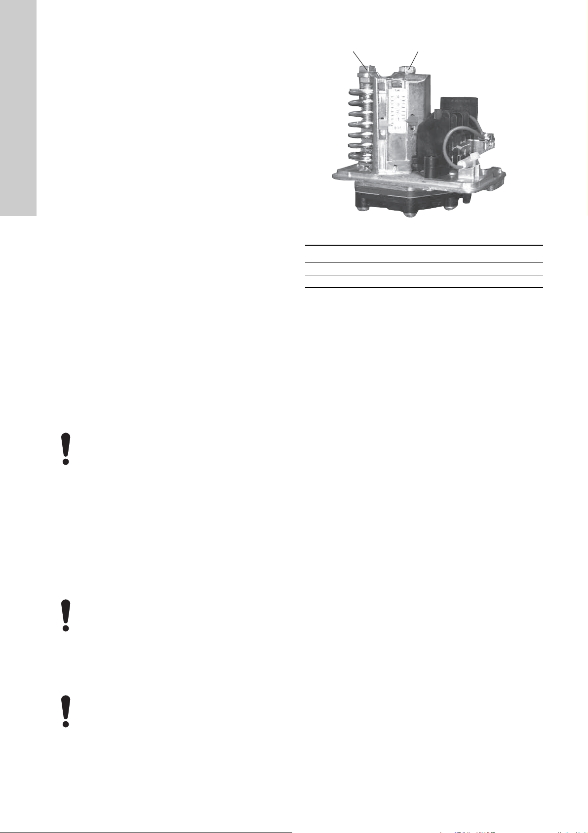
14.1 Dry-running protection
Hydro Multi-E must be protected against dry running.
Types of dry-running protection:
• a pressure switch which is factory-fitted to the inlet manifold.
See section 14.1.1 Pressure switch.
• a level switch fitted in a water tank. See section 14.1.2 Level
switch.
14.1.1 Pressure switch
As standard, Hydro Multi-E is fitted with an adjustable pressure
switch as dry-running protection. The pressure switch is fitted to
the inlet manifold.
If the inlet pressure is below the lower switching
point, the system cannot start.
If the pressure switch has stopped the system during
operation due to the inlet pressure being too low, the
inlet pressure must increase to a pressure that is
higher than the setting of the upper switching point
before the system can restart.
If necessary, adjust the lower switching point by turning screw A
and adjust the upper switching point to a value higher than the
lower switching point by turning screw B. See fig. 19.
Do not set the lower switching point to a value below
the minimum inlet pressure. See section
7.6 Minimum inlet pressure.
14
Page 15

14.1.2 Level switch
3
15
8
26
23
25
24
7
21
20
22
B
Y
6
5
2
4
10
A
+24 V*
1
14
9
12
17
19
11
18
+24 V*
+
+24 V*
OC
DI
+24 V*/5 V*
+24 V*
+
+
+
+24 V*/5 V*
+24 V*
+24 V*
+
+
+24 V*/5 V*
+24 V*
+5 V*
AI2
GDS RX
GDS TX
GND
GENIbus A
GENIbus B
+5 V
+24 V
+24 V
GND
GENIbus Y
GND
+5 V
DI1
AI1
DI3/OC1
LiqTec
AI3
GND
DI2
LiqTec
GND
AO
Pt100/1000
Pt100/1000
DI4/OC2
GND
+24 V*
OC
DI
GND
NC
C2
NO
NC
C1
NO
+5 V*
The system can be optionally fitted with a level switch, either from
factory or after delivery. The level switch can for instance monitor
the water level in a tank connected to the inlet manifold and be
connected to one of the digital inputs. See section Advanced
functional module (FM 300).
Furthermore, the digital input must be configured with a Grundfos
GO Remote to detect dry running.
The system must be restarted manually if it has been stopped
due to dry running.
Advanced functional module (FM 300)
Terminal Type Function
NC
C1 Common
NO
NC
C2 Common
NO
Normally closed
contact
Normally open
contact
Normally closed
contact
Normally open
contact
Signal relay 1
(LIVE or SELV)
Signal relay 2
(SELV only)
18 GND Ground
Digital input/output,
11 DI4/ OC2
configurable.
Open collector: Maximum
24 V resistive or inductive.
19 Pt100/1000 Pt100/1000 sensor input 2
17 Pt100/1000 Pt100/1000 sensor input 1
Analog output:
12 AO
0-20 mA / 4-20 mA
0-10 V
9 GND Ground
Analog input:
14 AI3
0-20 mA / 4-20 mA
0-10 V
1 DI2 Digital input, configurable
English (GB)
* If an external supply source is used, there must be a
connection to GND.
21 LiqTec
LiqTec sensor input 1
(white conductor)
Ground
20 GND
(brown and black
conductors)
22 LiqTec
LiqTec sensor input 2
(blue conductor)
Digital input/output,
10 DI3/OC1
configurable.
Open collector: Maximum
24 V resistive or inductive.
Analog input:
4AI1
0-20 mA / 4-20 mA
0.5 - 3.5 V / 0-5 V / 0-10 V
2 DI1 Digital input, configurable
5+5 V
Supply to potentiometer
and sensor
6 GND Ground
A GENIbus, A GENIbus, A (+)
Y GENIbus, Y GENIbus, GND
B GENIbus, B GENIbus, B (-)
3 GND Ground
15 +24 V Supply
8 +24 V Supply
TM05 3509 3512
26 +5 V
Supply to potentiometer
and sensor
23 GND Ground
25 GDS TX
24 GDS RX
Grundfos Digital Sensor
output
Grundfos Digital Sensor
input
Analog input:
7AI2
0-20 mA / 4-20 mA
0.5 - 3.5 V / 0-5 V / 0-10 V
15
Page 16

15. Bus signal
English (GB)
Bus communication is enabled via an RS-485 input.
The communication is carried out according to the Grundfos
GENIbus protocol and enables connection to a building
management system or another external control system.
Via a bus signal, it is possible to remote-set motor operating
parameters, such as setpoint and operating mode. At the same
time, the motor can, via the bus, provide status information about
important parameters, such as actual value of control parameter,
input power and fault indications.
Contact Grundfos for further information.
If a bus signal is used, the number of settings
available via Grundfos GO Remote will be reduced.
16. Priority of settings
The system can always be set to operate at maximum speed or to
stop with Grundfos GO Remote.
If two or more functions are enabled at the same time, the system
will operate according to the function with the highest priority.
Example: If, via the digital input, the system has been set to
maximum speed, the pump control panel or Grundfos GO Remote
can only set the system to "Manual" or "Stop".
The priority of the settings appears from the table below:
Priority Start/stop button
1Stop
2Stop*
3 Manual
4 Max. speed*
5 Stop
6 Stop
7 Max. speed
8 Min. speed
9 Start
10 Max. speed
11 Mi n . spee d
12 Min. speed
13 Start
14 Start
* If the bus communication is interrupted, the system will
resume its previous operating mode, for example "Stop",
selected on the control panel of the pump running as master or
with Grundfos GO Remote.
Control panel on pump or
Grundfos GO Remote
Digital input Bus communication
16
Page 17

17. Grundfos Eye
A
The operating condition of Hydro Multi-E is indicated by Grundfos
Eye on the pump control panels. See fig. 20, pos. A.
Fig. 20 Grundfos Eye
Grundfos Eye Indication Description
English (GB)
TM05 5993 4312
No lights are on.
The two opposite green indicator lights are
rotating in the direction of rotation of the
motor when seen from the non-drive end.
The two opposite green indicator lights are
permanently on.
One yellow indicator light is rotating in the
direction of rotation of the motor when seen
from the non-drive end.
One yellow indicator light is permanently on.
Two opposite red indicator lights are flashing
simultaneously.
The green indicator light in the middle
flashes quickly four times.
The green indicator light in the middle
flashes continuously.
The green indicator light in the middle is
permanently on.
Power off.
The motor is not running.
The power is on.
The motor is running.
The power is on.
The motor is not running.
Warning.
The motor is running.
Warning.
The motor has stopped.
Alarm.
The motor has stopped.
Remote control with Grundfos GO Remote via
radio.
The motor is trying to communicate with Grundfos
GO Remote. The motor is highlighted in the
Grundfos GO Remote display to inform the user
of the location of the motor.
When you have selected the motor in the
Grundfos GO Remote menu, the green indicator
light in the middle flashes continuously. Press
on the pump control panel to allow remote control
and data exchange via Grundfos GO Remote.
Remote control with Grundfos GO Remote via
radio.
The motor is communicating with Grundfos GO
Remote via radio connection.
The green indicator light in the middle
flashes quickly while Grundfos GO Remote
is exchanging data with the motor. It takes a
few seconds.
Remote control with Grundfos GO Remote via
infrared light.
The motor is receiving data from Grundfos GO
Remote via infrared communication.
17
Page 18

18. Signal relays
NCNOCNCNOCNCNOCNCNOCNCNO
C
C
NO NC
C
NO NCCNO NC
NCNOCNCNO
C
C
NO NC
C
NO NC
NCNOCNCNOCNCNO
C
NCNOCNCNO
C
C
NO NC
NCNOCNCNO
C
C
NO NC
C
NO NCCNO NC
NCNO
C
C
NO NC
C
NO NC
C
NO NC
NCNOCNCNO
C
C
NO NC
NCNOCNCNO
C
C
NO NC
NCNO
C
C
NO NC
C
NO NC
C
NO NC
NCNO
C
C
NO NC
NCNO
C
C
NO NC
C
NO NC
NCNO
C
C
NO NC
NCNO
C
NCNOCNCNOCNCNO
C
C
NO NC
NCNO
C
English (GB)
The motor has two outputs for potential-free signals via two
internal relays.
The signal outputs can be set to "Operation", "Running", "Ready",
"Alarm" and "Warning".
The functions of the two signal relays appear from the table
below:
Description Grundfos Eye
Power off.
Off
Pump running in "Normal"
mode.
Green, rotating
Pump running in "Manual"
mode.
Green, rotating
Pump in operating mode
"Stop".
Green, steady
Warning, but the pump is
running.
Yellow, rotating
Contact position for signal relays when activated
Operation Running Ready Alarm Warning
Operating
mode
-
Normal, Min.
or Max.
Manual
Stop
Normal, Min.
or Max.
Warning, but the pump is
running in "Manual" mode.
Warning, but the pump
was stopped via "Stop"
command.
Alarm, but the pump is
running.
Alarm, but the pump is
running in "Manual" mode.
Pump stopped due to an
alarm.
Manual
Yellow, rotating
Stop
Yellow, steady
Normal, Min.
or Max.
Red, rotating
Manual
Red, rotating
Stop
Red, flashing
18
Page 19

19. Digital input
Q
H
Q
H
10 s
Hydro Multi-E has a digital input for external faults. The input has
been factory-set to external fault and will be active in closed
condition.
Functional diagram: input for digital function
Digital function
(terminals 1 and 9)
Normal duty
External fault
21. Insulation resistance
Do not measure the insulation resistance of motor
windings or an installation incorporating motors with
integrated frequency converters using high-voltage
megging equipment, as this may damage the built-in
electronics.
22. Maintenance
DANGER
Electric shock
Death or serious personal injury
- Switch off the power supply and wait at least five
minutes before you start any work on the product.
Make sure that the power supply cannot be
accidentally switched on.
English (GB)
If the digital input is active for more than 10 seconds (s), Hydro
Multi-E will stop because of an external fault.
The digital input is used for the dry-running protection.
20. Data communication
It is possible to connect the system to an external network. The
connection can be made via a GENIbus-based network or a
network based on another fieldbus protocol.
The system can communicate via CIM modules. This enables the
system to communicate with different types of network solutions.
A CIM module is an add-on communication interface module. The
CIM module enables data transmission between the pump and an
external system, for example a BMS or SCADA system.
For further information on CIM modules, see www.grundfos.com
(Grundfos Product Center) or contact Grundfos.
22.1 Pumps
Pump bearings and shaft seals are maintenance-free.
If CRE or CRIE pumps are to be drained for a long period of
inactivity, remove one of the coupling guards to inject a few drops
of silicone oil on the shaft between the pump head and the
coupling. This will prevent the shaft seal faces from sticking.
22.2 Motors
Keep motor cooling fins and fan blades clean to ensure sufficient
cooling of the motor and electronics.
22.3 Breaker cabinet
The breaker cabinet is maintenance-free. Keep it clean and dry.
23. Shutdown
Shut down the system with the main switch in the breaker
cabinet.
DANGER
Electric shock
Death or serious personal injury
- Do not touch the conductors in front of the main
switch as they are still energised.
To shut down a pump, switch off the circuit breaker of the pump.
23.1 Frost protection
If pumps are not used during periods of frost, they must be
drained to avoid damage.
Drain the pump by loosening the vent screw in the pump head
and removing the drain plug from the base.
Do not tighten the vent screw or refit the drain plug until the
system is to be used again.
23.2 Service kits
See Grundfos Product Center for service manuals.
19
Page 20

24. Fault finding
English (GB)
Fault Cause Remedy
1. Hydro Multi-E does not run
when started.
2. Hydro Multi-E starts, but
stops immediately
afterwards. The operating
pressure is not reached.
3. Hydro Multi-E is stopped
and cannot restart.
4. Unstable water delivery
from Hydro Multi-E
(applies only to very low
consumption).
5. Pumps are running, but
deliver no water.
6. Hydro Multi-E is unable to
reach the setpoint.
7. Leakage from a shaft seal. a) The shaft seal is defective. Replace the shaft seal.
8. Noise. a) The pumps are cavitating. Clean the inlet pipe or pumps and possibly the inlet
9. Very frequent starts and
stops.
DANGER
Electric shock
Death or serious personal injury
- Switch off the power supply and wait at least five
minutes before you start any work on the product.
Make sure that the power supply cannot be
accidentally switched on.
a) The actual pressure is higher than or
equal to the setpoint set.
b) The power supply is disconnected. Connect the power supply.
c) The circuit breakers have cut out. Correct the fault and cut in the
d) The internal motor protection is activated. Contact Grundfos.
e) The circuit breaker is defective. Replace the circuit breaker.
f) The motor is defective. Repair or replace the motor.
g) Outlet-pressure sensor fault.
– The outlet-pressure sensor is defective. Replace the outlet-pressure sensor.
– The cable is broken or short-circuited. Repair or replace the cable.
a) Dry running or no inlet pressure. Check the supply of water to Hydro Multi-E. When the
a) Outlet-pressure sensor fault.
– The outlet-pressure sensor is defective. Replace the outlet-pressure sensor. Outlet-pressure
– The cable is broken or short-circuited. Repair or replace the cable.
b) Terminal box unit fault.
– The power supply is disconnected on
pump 1.
– The terminal box is defective. Replace the terminal box of pump 1.
a) The inlet pressure is too low. Check the inlet pipe and possible inlet strainer.
b) The inlet pipe or pumps are partly blocked
by impurities.
c) The pumps suck air. Check the inlet pipe for leakages.
d) The outlet-pressure sensor is defective. Replace the outlet-pressure sensor.
a) The inlet pipe or pumps are blocked by
impurities.
b) The non-return valve is blocked in the
closed position.
c) The inlet pipe is leaky. Check the inlet pipe for leakages.
d) Air in inlet pipe or pumps. Vent the pumps. Check the inlet pipe for leakages.
a) The cable is broken or short-circuited
(GENIbus communication between pump
1 and pump 2/3).
b) Pump 2 or 3 is out of operation. Connect the power supply to the pump and check the
b) CRE and CRIE pumps:
The height adjustment of the pump shaft
is inaccurate.
b) CRE and CRIE pumps:
The pumps do not rotate freely (frictional
resistance) due to inaccurate height
adjustment of the pump shaft.
a) Wrong diaphragm tank precharge
pressure.
b) The difference between start and stop
pressures is too small.
Note: This situation will only arise if
emergency operation is installed.
Wait until the pressure has dropped, or lower the
pressure on the outlet side of Hydro Multi-E, and check
that the booster system starts.
circuit breakers.
inlet pressure has been reestablished, the pumps will
restart after 15 seconds.
sensors with 0-20 mA or 4-20 mA output signals are
monitored by Hydro Multi-E.
Connect the power supply.
Contact Grundfos.
Clean the inlet pipe or pumps.
Clean the inlet pipe or pumps.
Clean the non-return valve. The non-return valve must
move freely.
Repair or replace the cable.
pump condition.
Readjust the shaft height.
strainer.
Readjust the shaft height. See the CR, CRI, CRN
installation and operating instructions supplied with
Hydro Multi-E.
Check the precharge pressure.
Increase the differential pressure setting on each
pressure switch.
20
Page 21

25. Technical data, Hydro Multi-E with single-phase pumps
25.1 Supply voltage
3 x 380-415 V - 10 %/+ 10 %, 50/60 Hz, N, PE.
Check that the supply voltage and frequency correspond to the
values stated on the nameplate.
Recommended fuse size
Motor size
[kW]
0.37 - 0.75 6 10
1.1 - 1.5 10 16
Standard as well as quick-blow or slow-blow fuses may be used.
Min.
[A]
Max.
[A]
25.2 Leakage current
Motor size
[kW]
0.37 - 1.5
The leakage currents are measured in accordance with EN
61800-5-1:2007.
Number of pumps in
booster system
2 Less than 7
3 Less than 10.5
4 Less than 14
Leakage current
[mA]
26. Technical data, Hydro Multi-E with three-phase pumps
26.1 Supply voltage
3 × 380-480 V - 10 %/+ 10 %, 50/60 Hz, PE.
Check that the supply voltage and frequency correspond to the
values stated on the nameplate.
Recommended fuse size
Motor size
[kW]
0.37 - 1.1 6 6
1.5 6 10
2.2 6 16
31016
41316
5.5 16 32
7.5 20 32
11 32 32
Standard as well as quick-blow or slow-blow fuses may be used.
26.2 Leakage current
Motor size
[kW]
0.3 - 11
(supply voltage less than
400 V)
0.37 - 11
(supply voltage greater
than 400 V)
The leakage currents are measured in accordance with EN
61800-5-1:2007.
Min.
[A]
Number of
pumps in
booster system
2 Less than 7
3 Less than 10.5
4 Less than 14
2 Less than 10
3 Less than 15
4 Less than 20
Max.
[A]
Leakage current
[mA]
27. Inputs and outputs
Ground reference (GND)
All voltages refer to GND.
All currents return to GND.
Absolute maximum voltage and current limits
Exceeding the following electrical limits may result in severely
reduced operating reliability a nd motor life:
Relay 1:
Maximum contact load: 250 VAC, 2 A or 30 VDC, 2 A.
Relay 2:
Maximum contact load: 30 VDC, 2 A.
GENI terminals: -5.5 to 9.0 VDC or less than 25 mADC.
Other input/output terminals: -0.5 to 26 VDC or less than 15
mADC.
Digital inputs (DI)
Internal pull-up current greater than 10 mA at Vi equal to 0 VDC.
Internal pull-up to 5 VDC (currentless for Vi greater than 5 VDC).
Certain low logic level: Vi less than 1.5 VDC.
Certain high logic level: Vi greater than 3.0 VDC.
Hysteresis: No.
Screened cable: 0.5 - 1.5 mm
Maximum cable length: 500 m.
Open-collector digital outputs (OC)
Current sinking capability: 75 mADC, no current sourcing.
Load types: Resistive and/or inductive.
Low-state output voltage at 75 mADC: Max. 1.2 VDC.
Low-state output voltage at 10 mADC: Max. 0.6 VDC.
Overcurrent protection: Yes.
Screened cable: 0.5 - 1.5 mm
Maximum cable length: 500 m.
Analog inputs (AI)
Voltage signal ranges:
• 0.5 - 3.5 VDC, AL AU.
• 0-5 VDC, AU.
• 0-10 VDC, AU.
Voltage signal: Ri is greater than 100 kΩ at +25 °C.
Leak currents may occur at high operating temperatures. Keep
the source impedance low.
Current signal ranges:
• 0-20 mADC, AU.
• 4-20 mADC, AL AU.
Current signal: Ri is equal to 292 Ω.
Current overload protection: Yes. Change to voltage signal.
Measurement tolerance: - 0/+ 3 % of full scale (max.-point
coverage).
Screened cable: 0.5 - 1.5 mm
Maximum cable length: 500 m (exclusive of potentiometer).
Potentiometer connected to +5 V, GND, any AI:
Use maximum 10 kΩ.
Maximum cable length: 100 m.
2
/ 28-16 AWG.
2
/ 28-16 AWG.
2
/ 28-16 AWG.
English (GB)
21
Page 22

Analog output (AO)
English (GB)
Current sourcing capability only.
Voltage signal:
• Range: 0-10 VDC.
• Minimum load between AO and GND: 1 kΩ.
• Short-circuit protection: Yes.
Current signal:
• Ranges: 0-20 and 4-20 mADC.
• Maximum load between AO and GND: 500 Ω.
• Open-circuit protection: Yes.
Tolerance: - 0/+ 4 % of full scale (max-point coverage).
Screened cable: 0.5 - 1.5 mm
Maximum cable length: 500 m.
Pt100/1000 inputs (PT)
Temperature range:
• Minimum -30 °C (88/882 Ω).
• Maximum +180 °C (168/1685 Ω).
Measurement tolerance: ± 1.5 °C.
Measurement resolution: Less than 0.3 °C.
Automatic range detection (Pt100 or Pt1000): Yes.
Sensor fault alarm: Yes.
Screened cable: 0.5 - 1.5 mm
Use Pt100 for short wires.
Use Pt1000 for long wires.
LiqTec sensor inputs
Use Grundfos LiqTec sensor only.
Screened cable: 0.5 - 1.5 mm
Grundfos Digital Sensor input and output (GDS)
Use Grundfos Digital Sensor only.
Power supplies (+5 V, +24 V)
+5 V:
• Output voltage: 5 VDC - 5 %/+ 5 %.
• Maximum current: 50 mADC (sourcing only).
• Overload protection: Yes.
+24 V:
• Output voltage: 24 VDC - 5 %/+ 5 %.
• Maximum current: 60 mADC (sourcing only).
• Overload protection: Yes.
Digital outputs (relays)
Potential-free changeover contacts.
Minimum contact load when in use: 5 VDC, 10 mA.
Screened cable: 0.5 - 2.5 mm
Maximum cable length: 500 m.
Bus input
Grundfos GENIbus protocol, RS-485.
Screened 3-core cable: 0.5 - 1.5 mm
Maximum cable length: 500 m.
2
/ 28-16 AWG.
2
/ 28-16 AWG.
2
/ 28-16 AWG.
2
/ 28-12 AWG.
2
/ 28-16 AWG.
28. Other technical data
EMC (electromagnetic compatibility)
According to EN 61000-6-2:2005 and 61000-6-3:2007.
Residential areas, unlimited distribution, corresponding to CISPR
11, class B, group 1.
Industrial areas, unlimited distribution, corresponding to CISPR
11, class A, group 1.
Contact Grundfos for further information.
Enclosure class
Standard: IP55 (IEC 34-5).
Insulation class
F (IEC 85).
Ambient temperature
• During operation: 0 to +40 °C.
• During storage or transport: -40 to +60 °C.
29. Sound pressure level
29.1 Hydro Multi-E with single-phase pumps
Motor size
[kW]
0.37 - 1.1
1.5
Number of pumps in
booster system
23
● 60
● 63
● 67
● 69
29.2 Hydro Multi-E with three-phase pumps
Motor size
[kW]
1.5
2.2
3.0
4.0
5.5
7.5
11
Number of pumps in
booster system
23
● 67
● 69
● 67
● 69
● 71
● 73
● 71
● 73
● 71
● 73
● 77
● 79
● 77
● 79
Sound pressure
level
[dB(A)]
Sound pressure
level
[dB(A)]
22
30. Disposal
This product or parts of it must be disposed of in an
environmentally sound way:
1. Use the public or private waste collection service.
2. If this is not possible, contact the nearest Grundfos company
or service workshop.
Subject to alterations.
Page 23

Appendix 1
0.0 0.4 0.8 1.2 1.6 2.0 2.4 Q [m³/h]
0
1
2
3
4
5
H
[m]
0.0 0.1 0.2 0.3 0.4 0.5 0.6 0.7 Q [l/s]
0
10
20
30
40
50
p
[kPa]
60 Hz
50 Hz
CR 1, CRI 1, CRN 1
CR(I)E 1
0 1 2 3 4 5 6 7 8 9 10 11 12 13 Q [m³/h]
0.0
0.5
1.0
1.5
2.0
2.5
3.0
3.5
4.0
H
[m]
0.0 0.5 1.0 1.5 2.0 2.5 3.0 3.5 Q [l/s]
0
10
20
30
40
p
[kPa]
60 Hz
50 Hz
CR 10, CRI 10, CRN 10
CR(I)E 10
0.0 0.8 1.6 2.4 3.2 4.0 4.8 Q [m³/h]
0
1
2
3
4
5
H
[m]
0.0 0.2 0.4 0.6 0.8 1.0 1.2 1.4 Q [l/s]
0
10
20
30
40
50
p
[kPa]
60 Hz
50 Hz
CR 3, CRI 3, CRN 3
CR(I)E 3
0 2 4 6 8 10 12 14 16 18 20 22 24 Q [m³/h]
0
1
2
3
4
5
H
[m]
0 1 2 3 4 5 6 7 Q [l/s]
0
16
32
48
p
[kPa]
60 Hz
50 Hz
CR 15, CRI 15, CRN 15
CR(I)E 15
0 1 2 3 4 5 6 7 8 9 10 Q [m³/h]
0
1
2
3
4
5
6
H
[m]
0.0 0.4 0.8 1.2 1.6 2.0 2.4 2.8 Q [l/s]
0
10
20
30
40
50
60
p
[kPa]
50 Hz
60 Hz
CR 5, CRI 5, CRN 5
CR(I)E 5
0 4 8 12 16 20 24 28 Q [m³/h]
0
1
2
3
4
5
6
H
[m]
0 2 4 6 8 Q [l/s]
0
16
32
48
p
60 Hz50 Hz
CR 20, CRI 20, CRN 20
CR(I)E 20
NPSH
Appendix
TM01 9882 1103
TM01 9883 1103
TM01 9884 1103
TM02 7125 2703
TM02 7126 2703
TM02 7127 2703
23
Page 24

Appendix
0 1 2 3 4 5 6 7 Q [m³/h]
0
2
4
6
8
10
H
[m]
0.0 0.5 1.0 1.5 2.0 Q [l/s]
0
20
40
60
80
100
p
[kPa]
50 Hz
60 Hz
CME-A/-I 5
0 2 4 6 8 10 12 14 16 Q [m³/h]
0
2
4
6
8
10
12
14
H
[m]
0 1 2 3 4 Q [l/s]
0
20
40
60
80
100
120
p
[kPa]
50 Hz
60 Hz
CME-A/-I 10
0 2 4 6 8 10 12 14 16 18 20 22 24 Q [m³/h]
0
2
4
6
8
10
12
H
[m]
0 1 2 3 4 5 6 7 Q [l/s]
0
20
40
60
80
100
120
p
[kPa]
50 Hz
60 Hz
CME-A/-I 15
20
15
12
10
8,0
6,0
5,0
4,0
3,0
2,0
1,0
0,8
0,6
0,4
0,3
0,2
0,1
1,5
120
110
90
100
80
70
60
50
40
30
20
10
0
Hv
(m)
tm
(°C)
150
130
140
25
35
45
40
30
TM05 2004 4211TM05 2005 4211TM05 2006 4211
Vapour pressure
24
TM00 3037 3493
Page 25

Declaration of conformity 2
GB: EC declaration of conformity
We, Grundfos, declare under our sole responsibility that the products
Hydro Multi-E, to which this declaration relates, are in conformity with
these Council directives on the approximation of the laws of the EC
member states:
DK: EU-overensstemmelseserklæring
Vi, Grundfos, erklærer under ansvar at produkterne Hydro Multi-E som
denne erklæring omhandler, er i overensstemmelse med disse af Rådets
direktiver om indbyrdes tilnærmelse til EU-medlemsstaternes lovgivning:
EE: EL vastavusdeklaratsioon
Meie, Grundfos, deklareerime enda ainuvastutusel, et toode Hydro
Multi-E, mille kohta käesolev juhend käib, on vastavuses EÜ Nõukogu
direktiividega EMÜ liikmesriikide seaduste ühitamise kohta, mis
käsitlevad:
ES: Declaración CE de conformidad
Nosotros, Grundfos, declaramos bajo nuestra entera responsabilidad
que los productos Hydro Multi-E, a los cuales se refiere esta declaración,
están conformes con las Directivas del Consejo en la aproximación de
las leyes de las Estados Miembros del EM:
HR: EZ izjava o usklađenosti
Mi, Grundfos, izjavljujemo pod vlastitom odgovornošću da je proizvod
Hydro Multi-E, na koji se ova izjava odnosi, u skladu s direktivama ovog
Vijeća o usklađivanju zakona država članica EU:
LV: EK atbilstības deklarācija
Sabiedrība GRUNDFOS ar pilnu atbildību dara zināmu, ka produkts
Hydro Multi-E, uz kuru attiecas šis paziņojums, atbilst šādām Padomes
direktīvām par tuvināšanos EK dalībvalstu likumdošanas normām:
HU: EK megfelelőségi nyilatkozat
Mi, a Grundfos, egyedüli felelősséggel kijelentjük, hogy a Hydro Multi-E
termékek, amelyekre jelen nyilatkozik vonatkozik, megfelelnek az
Európai Unió tagállamainak jogi irányelveit összehangoló tanács alábbi
előírásainak:
PL: Deklaracja zgodności WE
My, Grundfos, oświadczamy z pełną odpowiedzialnością, że nasze
wyroby Hydro Multi-E, których deklaracja niniejsza dotyczy, są zgodne
z następującymi wytycznymi Rady d/s ujednolicenia przepisów prawnych
krajów członkowskich WE:
RU: Декларация о соответствии ЕС
Мы, компания Grundfos, со всей ответственностью заявляем, что
изделия Hydro Multi-E, к которым относится настоящая декларация,
соответствуют следующим Директивам Совета Евросоюза об
унификации законодательных предписаний стран-членов ЕС:
SI: ES izjava o skladnosti
V Grundfosu s polno odgovornostjo izjavljamo, da so naši izdelki Hydro
Multi-E, na katere se ta izjava nanaša, v skladu z naslednjimi direktivami
Sveta o približevanju zakonodaje za izenačevanje pravnih predpisov
držav članic ES:
SE: EG-försäkran om överensstämmelse
Vi, Grundfos, försäkrar under ansvar att produkterna Hydro Multi-E, som
omfattas av denna försäkran, är i överensstämmelse med rådets direktiv
om inbördes närmande till EU-medlemsstaternas lagstiftning, avseende:
CZ: ES prohlášení o shodě
My firma Grundfos prohlašujeme na svou plnou odpovědnost, že výrobky
Hydro Multi-E na něž se toto prohlášení vztahuje, jsou v souladu
s ustanoveními směrnice Rady pro sblížení právních předpisů členských
států Evropského společenství v oblastech:
DE: EG-Konformitätserklärung
Wir, Grundfos, erklären in alleiniger Verantwortung, dass die Produkte
Hydro Multi-E, auf die sich diese Erklärung bezieht, mit den folgenden
Richtlinien des Rates zur Angleichung der Rechtsvorschriften der
EU-Mitgliedsstaaten übereinstimmen:
GR: ∆ήλωση συμμόρφωσης EC
Εμείς, η Grundfos, δηλώνουμε με αποκλειστικά δική μας ευθύνη ότι
τα προϊόντα Hydro Multi-E στα οποία αναφέρεται η παρούσα δήλωση,
συμμορφώνονται με τις εξής Οδηγίες του Συμβουλίου περί προσέγγισης
των νομοθεσιών των κρατών μελών της ΕΕ:
FR: Déclaration de conformité CE
Nous, Grundfos, déclarons sous notre seule responsabilité, que les
produits Hydro Multi-E, auxquels se réfère cette déclaration, sont
conformes aux Directives du Conseil concernant le rapprochement
des législations des Etats membres CE relatives aux normes énoncées
ci-dessous :
IT: Dichiarazione di conformità CE
Grundfos dichiara sotto la sua esclusiva responsabilità che i prodotti
Hydro Multi-E, ai quali si riferisce questa dichiarazione, sono conformi
alle seguenti direttive del Consiglio riguardanti il riavvicinamento delle
legislazioni degli Stati membri CE:
LT: EB atitikties deklaracija
Mes, Grundfos, su visa atsakomybe pareiškiame, kad gaminys Hydro
Multi-E, kuriam skirta ši deklaracija, atitinka šias Tarybos Direktyvas dėl
Europos Ekonominės Bendrijos šalių narių įstatymų suderinimo:
NL: EC overeenkomstigheidsverklaring
Wij, Grundfos, verklaren geheel onder eigen verantwoordelijkheid dat
de producten Hydro Multi-E waarop deze verklaring betrekking heeft,
in overeenstemming zijn met de Richtlijnen van de Raad in zake de
onderlinge aanpassing van de wetgeving van de EG Lidstaten
betreffende:
PT: Declaração de conformidade CE
A Grundfos declara sob sua única responsabilidade que os produtos
Hydro Multi-E, aos quais diz respeito esta declaração, estão em
conformidade com as seguintes Directivas do Conselho sobre
a aproximação das legislações dos Estados Membros da CE:
RO: Declaraţie de conformitate CE
Noi, Grundfos, declarăm pe propria răspundere că produsele Hydro
Multi-E, la care se referă această declaraţie, sunt în conformitate cu
aceste Directive de Consiliu asupra armonizării legilor Statelor Membre
CE:
FI: EY-vaatimustenmukaisuusvakuutus
Me, Grundfos, vakuutamme omalla vastuullamme, että tuotteet Hydro
Multi-E, joita tämä vakuutus koskee, ovat EY:n jäsenvaltioiden
lainsäädännön yhdenmukaistamiseen tähtäävien Euroopan neuvoston
direktiivien vaatimusten mukaisia seuraavasti:
TR: EC uygunluk bildirgesi
Grundfos olarak bu beyannameye konu olan Hydro Multi-E ürünlerinin,
AB Üyesi Ülkelerin kanunlarını birbirine yaklaştırma üzerine Konsey
Direktifleriyle uyumlu olduğunun yalnızca bizim sorumluluğumuz altında
olduğunu beyan ederiz:
Declaration of conformity
25
Page 26

Declaration of conformity
— Machinery Directive (2006/42/EC).
Standards used:
EN 809:1998 and A1:2009.
— Radio Equipment Directive (2014/53/EU)
Standards used:
EN 61800-5-1:2007, EN 61800-3:2004+A1:2012, EN 62479:2010,
EN 301 489-1 V2.2.0, EN 301 489-17 V2.2.1, EN 300 328 V1.9.1,
EN 301 511 V12.1.10, EN 301 489-1 V2.2.0, EN 301 489-7 V1.3.
— ErP Directive (2009/125/EC)
Motors:
Commision Regulation (EC) No 640/2009
Standards used:
EN 60034-2-1:2007
Water pumps:
Commission Regulation No 547/2012.
Applies only to water pumps marked with the minimum efficiency
index MEI. See pump nameplate.
This EC declaration of conformity is only valid when published as part of
the Grundfos installation and operating instructions (publication number
98491894 0517).
Bjerringbro, 7th April 2017
Svend Aage Kaae
Technical Director
Grundfos Holding A/S
Poul Due Jensens Vej 7
8850 Bjerringbro, Denmark
Person authorised to compile technical file and
empowered to sign the EC declaration of conformity.
26
Page 27

Operating manual EAC 3
RUS
Hydro Multi-E
Руководство по эксплуатации
Руководство по эксплуатации на данное изделие является составным и включает в себя несколько частей:
Часть 1: настоящее «Руководство по эксплуатации».
Часть 2: электронная часть «Паспорт. Руководство по монтажу и эксплуатации» размещенная на сайте
компании Грундфос. Перейдите по ссылке, указанной в конце документа.
Часть 3: информация о сроке изготовления, размещенная на фирменной табличке изделия.
Сведения о сертификации:
Насосы типа Hydro Multi-E сертифицированы на соответствие требованиям Технических регламентов
Таможенного союза: ТР ТС 004/2011 «О безопасности низковольтного оборудования»; ТР ТС 010/2011 «О
безопасности машин и оборудования»; ТР ТС 020/2011 «Электромагнитная совместимость технических
средств».
KAZ
Hydro Multi-E
Пайдалану бойынша нұсқаулық
Атаулы өнімге арналған пайдалану бойынша нұсқаулық құрамалы болып келеді және келесі бөлімдерден
тұрады:
1 бөлім: атаулы «Пайдалану бойынша нұсқаулық»
2 бөлім: Грундфос компаниясының сайтында орналасқан электронды бөлім «Төлқұжат, Құрастыру жəне
пайдалану бойынша нұсқаулық». Құжат соңында көрсетілген сілтеме арқылы өтіңіз.
3 бөлім: өнімнің фирмалық тақташасында орналасқан шығарылған уақыты жөніндегі мәлімет
Сертификаттау туралы ақпарат:
Hydro Multi-E типті сорғылары «Төмен вольтты жабдықтардың қауіпсіздігі туралы» (ТР ТС 004/2011),
«Машиналар және жабдықтар қауіпсіздігі туралы» (ТР ТС 010/2011) «Техникалық заттардың электрлі магниттік
сәйкестілігі» (ТР ТС 020/2011) Кеден Одағының техникалық регламенттерінің талаптарына сәйкес
сертификатталды.
Operating manual EAC
27
Page 28

Operating manual EAC
KG
Hydro Multi-E
Пайдалануу боюнча колдонмо
Аталган жабдууну пайдалануу боюнча колдонмо курамдык жана өзүнө бир нече бөлүкчөнү камтыйт:
1-Бөлүк: «Пайдалануу боюнча колдонмо»
2-Бөлүк: «Паспорт. Пайдалануу жана монтаж боюнча колдонмо» электрондук бөлүгү Грундфос компаниянын
сайтында жайгашкан. Документтин аягында көрсөтүлгөн шилтемеге кайрылыңыз.
3-Бөлүк: жабдуунун фирмалык тактасында жайгашкан даярдоо мөөнөтү тууралуу маалымат.
Шайкештик жөнүндө декларация
Hydro Multi-E 2.2 түрүндөгү соргучтар Бажы Биримдиктин Техникалык регламенттин талаптарына ылайыктуу
тастыкталган: ТР ТБ 004/2011 «Төмөн вольттук жабдуунун коопсуздугу жөнүндө»; ТР ТБ 010/2011 «Жабдуу
жана машиналардын коопсуздугу жөнүндө»; ТР ТБ 020/2011 «Техникалык каражаттардын электрмагниттик
шайкештиги».
ARM
Hydro Multi-E
Շահագործման ձեռնարկ
Տվյալ սարքավորման շահագործման ձեռնարկը բաղկացած է մի քանի մասերից.
Մաս 1. սույն «Շահագործման ձեռնարկ»:
Մաս 2. էլեկտրոնային մաս. այն է՝ «Անձնագիր: Մոնտաժման և
շահագործման ձեռնարկ» տեղադրված «Գրունդֆոս». Անցեք փաստաթղթի վերջում նշված հղումով.
Մաս 3. տեղեկություն արտադրման ամսաթվի վերաբերյալ՝ նշված սարքավորման պիտակի վրա:
Տեղեկություններ հավաստագրման մասին՝
Hydro Multi-E տիպի պոմպերը սերտիֆիկացված են համաձայն Մաքսային Միության տեխնիկական
կանոնակարգի պահանջների՝ ТР ТС 004/2011 «Ցածրավոլտ սարքավորումների վերաբերյալ», ТР ТС
010/2011«Մեքենաների և սարքավորումների անվտանգության վերաբերյալ» ; ТР ТС 020/2011
«Տեխնիկական միջոցների էլեկտրամագնիսական համատեղելիության վերաբերյալ»:
http://net.grundfos.com/qr/i/
98881635
10000136811
0517
ECM: 1209618
28
Page 29

Argentina
Bombas GRUNDFOS de Argentina S.A.
Ruta Panamericana km. 37.500 Centro
Industrial Garin
1619 Garín Pcia. de B.A.
Phone: +54-3327 414 444
Telefax: +54-3327 45 3190
Australia
GRUNDFOS Pumps Pty. Ltd.
P.O. Box 2040
Regency Park
South Australia 5942
Phone: +61-8-8461-4611
Telefax: +61-8-8340 0155
Austria
GRUNDFOS Pumpen Vertrieb Ges.m.b.H.
Grundfosstraße 2
A-5082 Grödig/Salzburg
Tel.: +43-6246-883-0
Telefax: +43-6246-883-30
Belgium
N.V. GRUNDFOS Bellux S.A.
Boomsesteenweg 81-83
B-2630 Aartselaar
Tél.: +32-3-870 7300
Télécopie: +32-3-870 7301
Belarus
Представительство ГРУНДФОС в
Минске
220125, Минск
ул. Шафарнянская, 11, оф. 56, БЦ
«Порт»
Тел.: +7 (375 17) 286 39 72/73
Факс: +7 (375 17) 286 39 71
E-mail: minsk@grundfos.com
Bosnia and Herzegovina
GRUNDFOS Sarajevo
Zmaja od Bosne 7-7A,
BH-71000 Sarajevo
Phone: +387 33 592 480
Telefax: +387 33 590 465
www.ba.grundfos.com
e-mail: grundfos@bih.net.ba
Brazil
BOMBAS GRUNDFOS DO BRASIL
Av. Humberto de Alencar Castelo Branco,
630
CEP 09850 - 300
São Bernardo do Campo - SP
Phone: +55-11 4393 5533
Telefax: +55-11 4343 5015
Bulgaria
Grundfos Bulgaria EOOD
Slatina District
Iztochna Tangenta street no. 100
BG - 1592 Sofia
Tel. +359 2 49 22 200
Fax. +359 2 49 22 201
email: bulgaria@grundfos.bg
Canada
GRUNDFOS Canada Inc.
2941 Brighton Road
Oakville, Ontario
L6H 6C9
Phone: +1-905 829 9533
Telefax: +1-905 829 9512
China
GRUNDFOS Pumps (Shanghai) Co. Ltd.
10F The Hub, No. 33 Suhong Road
Minhang District
Shanghai 201106
PRC
Phone: +86 21 612 252 22
Telefax: +86 21 612 253 33
COLOMBIA
GRUNDFOS Colombia S.A.S.
Km 1.5 vía Siberia-Cota Conj. Potrero
Chico,
Parque Empresarial Arcos de Cota Bod.
1A.
Cota, Cundinamarca
Phone: +57(1)-2913444
Telefax: +57(1)-8764586
Croatia
GRUNDFOS CROATIA d.o.o.
Buzinski prilaz 38, Buzin
HR-10010 Zagreb
Phone: +385 1 6595 400
Telefax: +385 1 6595 499
www.hr.grundfos.com
GRUNDFOS Sales Czechia and
Slovakia s.r.o.
Čajkovského 21
779 00 Olomouc
Phone: +420-585-716 111
Denmark
GRUNDFOS DK A/S
Martin Bachs Vej 3
DK-8850 Bjerringbro
Tlf.: +45-87 50 50 50
Telefax: +45-87 50 51 51
E-mail: info_GDK@grundfos.com
www.grundfos.com/DK
Estonia
GRUNDFOS Pumps Eesti OÜ
Peterburi tee 92G
11415 Tallinn
Tel: + 372 606 1690
Fax: + 372 606 1691
Finland
OY GRUNDFOS Pumput AB
Trukkikuja 1
FI-01360 Vantaa
Phone: +358-(0) 207 889 500
France
Pompes GRUNDFOS Distribution S.A.
Parc d’Activités de Chesnes
57, rue de Malacombe
F-38290 St. Quentin Fallavier (Lyon)
Tél.: +33-4 74 82 15 15
Télécopie: +33-4 74 94 10 51
Germany
GRUNDFOS GMBH
Schlüterstr. 33
40699 Erkrath
Tel.: +49-(0) 211 929 69-0
Telefax: +49-(0) 211 929 69-3799
e-mail: infoservice@grundfos.de
Service in Deutschland:
e-mail: kundendienst@grundfos.de
Greece
GRUNDFOS Hellas A.E.B.E.
20th km. Athinon-Markopoulou Av.
P.O . B o x 7 1
GR-19002 Peania
Phone: +0030-210-66 83 400
Telefax: +0030-210-66 46 273
Hong Kong
GRUNDFOS Pumps (Hong Kong) Ltd.
Unit 1, Ground floor
Siu Wai Industrial Centre
29-33 Wing Hong Street &
68 King Lam Street, Cheung Sha Wan
Kowloon
Phone: +852-27861706 / 27861741
Telefax: +852-27858664
Hungary
GRUNDFOS Hungária Kft.
Park u. 8
H-2045 Törökbálint,
Phone: +36-23 511 110
Telefax: +36-23 511 111
India
GRUNDFOS Pumps India Private Limited
118 Old Mahabalipuram Road
Thoraipakkam
Chennai 600 096
Phone: +91-44 2496 6800
Indonesia
PT. GRUNDFOS POMPA
Graha Intirub Lt. 2 & 3
Jln. Cililitan Besar No.454. Makasar,
Jakarta Timur
ID-Jakarta 13650
Phone: +62 21-469-51900
Telefax: +62 21-460 6910 / 460 6901
Ireland
GRUNDFOS (Ireland) Ltd.
Unit A, Merrywell Business Park
Ballymount Road Lower
Dublin 12
Phone: +353-1-4089 800
Telefax: +353-1-4089 830
Italy
GRUNDFOS Pompe Italia S.r.l.
Via Gran Sasso 4
I-20060 Truccazzano (Milano)
Tel.: +39-02-95838112
Telefax: +39-02-95309290 / 95838461
Japan
GRUNDFOS Pumps K.K.
1-2-3, Shin-Miyakoda, Kita-ku,
Hamamatsu
431-2103 Japan
Phone: +81 53 428 4760
Telefax: +81 53 428 5005
Korea
GRUNDFOS Pumps Korea Ltd.
6th Floor, Aju Building 679-5
Yeoksam-dong, Kangnam-ku, 135-916
Seoul, Korea
Phone: +82-2-5317 600
Telefax: +82-2-5633 725
Latvia
SIA GRUNDFOS Pumps Latvia
Deglava biznesa centrs
Augusta Deglava ielā 60, LV-1035, Rīga,
Tālr.: + 371 714 9640, 7 149 641
Fakss: + 371 914 9646
Lithuania
GRUNDFOS Pumps UAB
Smolensko g. 6
LT-03201 Vilnius
Tel: + 370 52 395 430
Fax: + 370 52 395 431
Malaysia
GRUNDFOS Pumps Sdn. Bhd.
7 Jalan Peguam U1/25
Glenmarie Industrial Park
40150 Shah Alam
Selangor
Phone: +60-3-5569 2922
Telefax: +60-3-5569 2866
Mexico
Bombas GRUNDFOS de México S.A. de
C.V.
Boulevard TLC No. 15
Parque Industrial Stiva Aeropuerto
Apodaca, N.L. 66600
Phone: +52-81-8144 4000
Telefax: +52-81-8144 4010
Netherlands
GRUNDFOS Netherlands
Velu we zo om 35
1326 AE Almere
Postbus 22015
1302 CA ALMERE
Tel.: +31-88-478 6336
Telefax: +31-88-478 6332
E-mail: info_gnl@grundfos.com
New Zealand
GRUNDFOS Pumps NZ Ltd.
17 Beatrice Tinsley Crescent
North Harbour Industrial Estate
Albany, Auckland
Phone: +64-9-415 3240
Telefax: +64-9-415 3250
Norway
GRUNDFOS Pumper A/S
Strømsveien 344
Postboks 235, Leirdal
N-1011 Oslo
Tlf.: +47-22 90 47 00
Telefax: +47-22 32 21 50
Poland
GRUNDFOS Pompy Sp. z o.o.
ul. Klonowa 23
Baranowo k. Poznania
PL-62-081 Przeźmierowo
Tel: (+48-61) 650 13 00
Fax: (+48-61) 650 13 50
Portugal
Bombas GRUNDFOS Portugal, S.A.
Rua Calvet de Magalhães, 241
Apartado 1079
P-2770-153 Paço de Arcos
Tel.: +351-21-440 76 00
Telefax: +351-21-440 76 90
Romania
GRUNDFOS Pompe România SRL
Bd. Biruintei, nr 103
Pantelimon county Ilfov
Phone: +40 21 200 4100
Telefax: +40 21 200 4101
E-mail: romania@grundfos.ro
Russia
ООО Грундф ос Россия
Shkolnaya, 39-41
Москва, RU-109544, Russia
Тел. (+7) 495 564-88-00 (495) 737-30-00
Факс (+7) 495 564 88 11
E-mail grundfos.moscow@grundfos.com
Serbia
Grundfos Srbija d.o.o.
Omladinskih brigada 90b
11070 Novi Beograd
Phone: +381 11 2258 740
Telefax: +381 11 2281 769
www.rs.grundfos.com
Singapore
GRUNDFOS (Singapore) Pte. Ltd.
25 Jalan Tukang
Singapore 619264
Phone: +65-6681 9688
Telefax: +65-6681 9689
Slovakia
GRUNDFOS s.r.o.
Prievozská 4D
821 09 BRATISLAVA
Phona: +421 2 5020 1426
sk.grundfos.com
Slovenia
GRUNDFOS LJUBLJANA, d.o.o.
Leskoškova 9e, 1122 Ljubljana
Phone: +386 (0) 1 568 06 10
Telefax: +386 (0)1 568 06 19
E-mail: tehnika-si@grundfos.com
South Africa
GRUNDFOS (PTY) LTD
Corner Mountjoy and George Allen Roads
Wilbart Ext. 2
Bedfordview 2008
Phone: (+27) 11 579 4800
Fax: (+27) 11 455 6066
E-mail: lsmart@grundfos.com
Spain
Bombas GRUNDFOS España S.A.
Camino de la Fuentecilla, s/n
E-28110 Algete (Madrid)
Tel.: +34-91-848 8800
Telefax: +34-91-628 0465
Sweden
GRUNDFOS AB
Box 333 (Lunnagårdsgatan 6)
431 24 Mölndal
Tel.: +46 31 332 23 000
Telefax: +46 31 331 94 60
Switzerland
GRUNDFOS Pumpen AG
Bruggacherstrasse 10
CH-8117 Fällanden/ZH
Tel.: +41-44-806 8111
Telefax: +41-44-806 8115
Taiwan
GRUNDFOS Pumps (Taiwan) Ltd.
7 Floor, 219 Min-Chuan Road
Taichung, Taiwan, R.O.C.
Phone: +886-4-2305 0868
Telefax: +886-4-2305 0878
Thailand
GRUNDFOS (Thailand) Ltd.
92 Chaloem Phrakiat Rama 9 Road,
Dokmai, Pravej, Bangkok 10250
Phone: +66-2-725 8999
Telefax: +66-2-725 8998
Turkey
GRUNDFOS POMPA San. ve Tic. Ltd. Sti.
Gebze Organize Sanayi Bölgesi
Ihsan dede Caddesi,
2. yol 200. Sokak No. 204
41490 Gebze/ Kocaeli
Phone: +90 - 262-679 7979
Telefax: +90 - 262-679 7905
E-mail: satis@grundfos.com
Ukraine
Бізнес Центр Європа
Столичне шосе, 103
м. Київ, 03131, Україна
Телефон : (+38 044) 237 04 00
Факс.: (+38 044) 237 04 01
E-mail: ukraine@grundfos.com
United Arab Emirates
GRUNDFOS Gulf Distribution
P.O. Box 16768
Jebel Ali Free Zone
Dubai
Phone: +971 4 8815 166
Telefax: +971 4 8815 136
United Kingdom
GRUNDFOS Pumps Ltd.
Grovebury Road
Leighton Buzzard/Beds. LU7 4TL
Phone: +44-1525-850000
Telefax: +44-1525-850011
U.S.A.
GRUNDFOS Pumps Corporation
17100 West 118th Terrace
Olathe, Kansas 66061
Phone: +1-913-227-3400
Telefax: +1-913-227-3500
Uzbekistan
Grundfos Tashkent, Uzbekistan The Representative Office of Grundfos Kazakhstan in
Uzbekistan
38a, Oybek street, Tashkent
Телефон: (+998) 71 150 3290 / 71 150
3291
Факс: (+998) 71 150 3292
Addresses Revised 07.06.2017
Grundfos companies
Page 30

98491894 0517
ECM: 1173360
www.grundfos.com
The name Grundfos, the Grundfos logo, and be think innovate are registered trademarks owned by Grundfos Holding A/S or Grundfos A/S, Denmark. All rights reserved worldwide. © Copyright Grundfos Holding A/S
 Loading...