

Page 1

GRUNDFOS INSTRUCTIONS
Rigid Suction Lances RSL
and Foot Valves FV
Installation and operating instructions
Page 2

2
Page 3

English (GB) Installation and operating instructions
Caution
Note
Original installation and operating instructions.
CONTENTS
1. Safety instructions
1.1 Symbols used in this document
1.2 Qualification and training of personnel
1.3 Safe operation
1.4 Safety instructions for the operating company/operator
2. Product introduction
2.1 Applications
2.2 Improper operating methods
2.3 Function
2.4 Warranty
2.5 Product description
2.6 Identification
3. Technical data
3.1 Dimensions
4. Installation
4.1 Hydraulic connection
4.2 Electrical connection of level indication
4.3 Container connection
5. Maintenance and service
5.1 Maintenance
5.2 Service
6. Fault finding
7. Disposal
Page
10
12
12
12
13
13
1.4 Safety instructions for the operating
company/operator
The owner of the system is responsible for training of operating
personnel.
3
3
3
3
3
3
3
3
3
4
4
5
6
7
8
8
9
Warnin g
When working with chemicals, the accident
prevention regulations applicable at the
installation site must be applied.
Observe the chemical manufacturer's safety data
sheets when handling chemicals.
Warnin g
When working on the product, or connections
and lines, always wear protective clothing (e.g.
safety goggles and gloves).
The system must be unpressurised.
Only operate the system if all lines are connected
correctly.
Warnin g
The chemical resistance of the parts that come
into contact with the dosing medium depends on
the medium, media temperature and operating
pressure.
Ensure that all parts in contact with the medium
are resistant to th e med ium un der opera tin g
conditions.
English (GB)
Warning
Prior to installation, read these installation and
operating instructions. Installation and operation
must comply with local regulations and accepted
codes of good practice.
1. Safety instructions
1.1 Symbols used in this document
The safety instructions are identified by the following symbols:
Warning
If these safety instructions are not observed,
it may result in personal injury.
If these safety instructions are not observed,
it may result in malfunction or damage to the
equipment.
Notes or instructions that make the job easier
and ensure safe operation.
1.2 Qualification and training of per sonne l
The personnel responsible for the installation, operation and
service must be appropriately qualified for these tasks.
Areas of responsibility, levels of authority and the supervision of
the personnel must be precisely defined by the operator.
If necessary, the personnel must be trained appropriately.
1.3 Safe operation
If safe operation is no longer possible, the product must be taken
out of operation and secured against unintentional operation.
This is the case in the following situations:
• If the product is visibly damaged.
• If the product no longer seems operational.
• After long periods of storage under unfavourable conditions.
2. Product introduction
2.1 Applications
The foot valve and the rigid suction lance are suitable for the
following applications:
• Extraction of chemicals from unpressurised containers.
• Monitoring the liquid level in the chemical container (versions
with two-step level indication).
Special features:
• Protection of the suction assembly (suction lance).
• Easy handling when exchanging containers.
2.2 Improper operating methods
Warnin g
Improper use, foreseeable misuse or
misapplication can lead to personal injury and
damage to the equipment and is therefore not
permitted.
The operational safety of the product is only guaranteed, if it is
used in accordance with section 2.1 Applications.
The product may not be used for:
• operation in potentially explosive areas
• combustible media
• frozen media
• abrasive or crystallising media.
2.3 Function
• Extracting liquid from a container with a suction line.
• Filtering the liquid to protect the pump from soiling.
• Preventing backflow of liquid by means of a non-return valve.
• Keeping the foot valve upright at the container bottom.
• Indicating a low level of liquid or an empty tank by means of
two reed switches and floaters.
• Connecting an exchangeable container.
3
Page 4

2.4 Warranty
Note
1
1
2
3
4
5
6
7
8
9
10
11
7/9
7
10
1
English (GB)
A warranty claim in accordance with our general terms of sale
and delivery is only valid if these requirements are fulfilled:
• The product is used in accordance with the information within
this manual.
• The product is not dismantled or handled incorrectly.
• Maintenance is carried out by authorised and qualified
personnel.
• Only original spare parts are used for repairs during
maintenance.
Grundfos cannot be held liable for any damage
resulting from incorrect use.
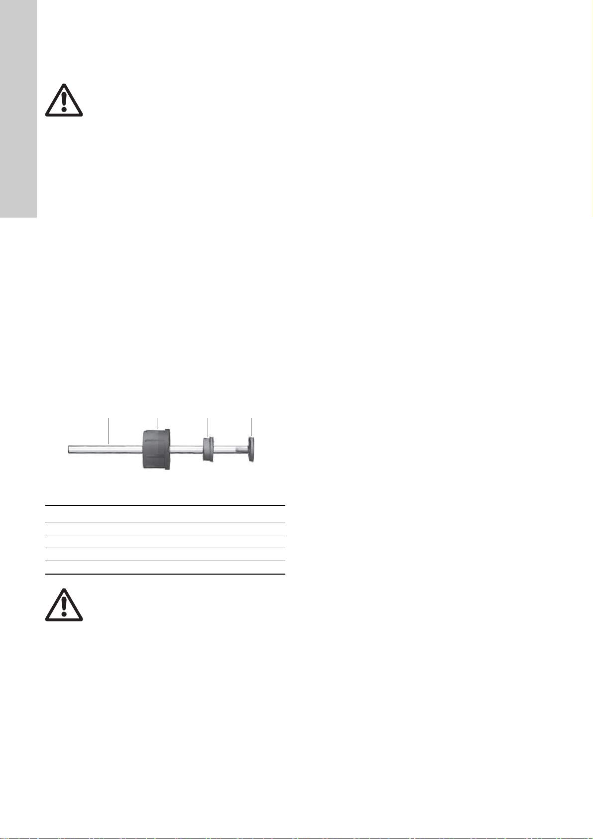
2.5 Product description
Fig. 1 From left to right: suction lance, foot valve with level indication, plastic and stainless-steel foot valve without level indication
Pos. Description
1 Hose connection thread
2 Signal cable with plug
3 Tank connection, slidable
4 Tank cap, slidable
5 Protective tube with hose
6 Floater low-level
7 Valve body with switch unit
8 Floater empty
9 Inlet with strainer
10 Inlet with strainer and weight
11 Connection for hose or pipe
TM04 8524 1212
4
Page 5

2.6 Identification
2.6.1 Type key of suction lances
Code Example RSL - 0500 - 2L - G5/8 PE / V,E / C U2
RSL Rigid Suction Lance
Maximum immersion depth
0400 up to 400 mm
0500 up to 500 mm
0570 up to 570 mm
0690 up to 690 mm
0820 up to 820 mm
0980 up to 980 mm
1100 up to 1100 mm
1200 up to 1200 mm
Level indication
NL Without level indication
2L Two-step level indication (low-level signal, tank-empty signal)
Connection size
G5/8 Male thread G 5/8 with groove for O-Ring on top
Material of enclosure, connection, floater
PE High density polyethylene (HDPE)
PV Polyvinylidenfluoride (PVDF)
Material of O-ring
V,E Fluorocarbon elastomer (FKM) and ethylene propylene diene rubber (EPDM)
T Polytetrafluorethylene (PTFE)
Material of ball
CCeramic
Connections for hose
U2 Hose connection set: 4/6 mm, 6/9 mm, 6/12 mm, 9/12 mm
U7 Hose connection set: 0.17" x 1/4", 1/4" x 3/8", 3/8" x 1/2"
X Without connections
English (GB)
2.6.2 Type key of foot valves
Code Example FV - 2L - G5/8 PE / V,E / C U2
FV Foot valve
Level indication
NL Without level indication
2L Two-step level indication (low-level signal, tank-empty signal)
Connection size
G5/8 Male thread G 5/8 with groove for O-Ring on top
Material of enclosure, connection, floater
PE High density polyethylene (HDPE)
PV Polyvinylidenfluoride (PVDF)
SS Stainless steel 1.4571
Material of O-ring
V,E Fluorocarbon elastomer (FKM) and ethylene propylene diene rubber (EPDM)
T Polytetrafluorethylene (PTFE)
Material of ball
C Ceramic
SS Stainless steel 1.4401
Connections for hose or pipe
U2 Hose connection set: 4/6 mm, 6/9 mm, 6/12 mm, 9/12 mm
U7 Hose connection set: 0.17" x 1/4", 1/4" x 3/8", 3/8" x 1/2"
A Threaded pipe connection Rp 1/4" (G 1/4" female)
V Threaded pipe connection 1/4" (NPT female)
X Without connections
5
Page 6

3. Technical data
English (GB)
Data
Mechanical data
Max. flow rate
Max. pressure
1)
2)
[l/h] 60
[gph] 15.85
[bar] 2
[psi] 29
Max. liquid temperature [°C] 45 60 80
Min. liquid temperature [°C] 0 0 -10
Foot valve and
suction lance (PE)
Max. ambient temperature [°C] 45
Min. ambient temperature [°C] 0 0 -10
Max. storage temperature [°C] 45
Min. storage temperature [°C] 0 0 -10
3)
[m] 5 5 -
Electrical data
(for versions with
two-step level
indication)
Length of included signal cable
Type of included signal cable LIY2Y LIY2Y -
Max. voltage of reed switches [V] 48 48 -
Max. current of reed switches [A] 0.5 0.5 -
Max. load of reed switches [VA] 10 10 -
Suction lance [kg] 0.28 - 0.4 0.43 - 0.62 -
Weight
4)
Foot valve without level
indication
[kg] 0.11 0.13 0.18
Foot valve with level indication [kg] 0.26 0.28 -
1)
Liquids with viscosity similar to water
2)
Applies to the inside of the suction installation. The container must be unpressurised!
3)
Also for suction lances, the indicated cable length is measured starting from the valve body
4)
When installed, without packaging
Foot valve and
suction lance
(PVDF)
Foot valve
(stainless steel)
6
Page 7

3.1 Dimensions
/
/
/
/
/
/
*
'
*
'
/
/
/
*
'
'
/
'
'
'
$
$
/
/
'
*
/
/
'
*
English (GB)
TM04 8445 4511, TM04 8447 4511
Fig. 2 Left: rigid suction lance with / without level indication, right: foot valve with level indication
Dimensions [mm]
Code
Suction lance Foot valve
L1 see type key 2.6.1 196
L2 ≥ 114 ~ 103.5
L3 ≥ 103 ~ 43.5
L4 ~ 85 18.5
L5 ~ 25 L6 4.5 D1 68.5 35
D2 32 58
D3 - 12
D4 - 9
D5 - 6
Fig. 3 Foot valve without level indication. Left: PE and PVDF
version, right: stainless-steel version
Dimensions [mm]
Code
Foot valve PE, PVDF Foot valve stainless steel
TM04 8446 4511, TM04 8494 0612
L1 67.5 30
L2 19 4
D1 35 30
7
Page 8
4. Installation
1
2
3
4
English (GB)
4.1 Hydraulic connection
Warning
Danger of chemical burn!
Avoid direct contact with chemicals.
Wear protective clothing when handling
chemicals.
4.1.1 Conditions for installation
• Proper functioning can only be guaranteed when using
Grundfos accessories.
• For suction height and line diameter, please see the technical
data of the pump.
4.1.2 Notes for installa tion
• Shorten the hoses at right angles.
• Make sure there are no loops or kinks in the hoses.
• Keep the suction line as short as possible.
• Install the suction line upwards to the suction valve of the
pump.
4.1.3 Connecting the hose (fig. 4)
1. Slide union nut (2) and tensioning ring (3) onto the hose (1).
2. Insert the cone part (4) fully into the hose.
3. Put the cone part with hose onto the corresponding threaded
connection of foot valve / suction lance or suction valve of the
pump.
4. Tighten union nut manually. Do not use any tools!
– Tighten up union nut after 2-5 operating hours if using
PTFE gaskets!
5. If existing, insert the deaeration line of the pump and the relief
line of the multi-function or pressure relief valve via the
corresponding connection of the foot valve or suction lance
into the container.
Fig. 4 Hydraulic connection
Pos. Description
1Hose
2 Union nut
3 Tensioning ring
4 Cone part
Warning
Do not immerse the return lines into the liquid.
TM04 8559 2212
8
Page 9

4.2 Electrical connection of level indication
Note
2
1
3
GND
34
12
Note
1
2
In order to monitor the filling level of the container, a two-step
level indication (low-level signal, tank-empty signal) can be connected to the pump or other downstream devices.
Observe the manuals of the downstream devices.
4.2.1 Signal connection with round plug
All SMART Digital pumps and the digital dosing pump DDI 222
are connected with round plugs.
4.2.3 Changing the contact type
Suction lances and foot valves with two-step level indication have
two signal outputs. Both are factory-set to NO contact type.
The symbol is on the floater top (see fig. 7).
• The symbol that is visible from above shows the switch mode
"floater above".
• The symbol that is visible from below shows the switch mode
"floater below".
The contact type can be changed from NO to NC by turning the
floater horizontally by 180 °. A cable break will provoke a
tank-empty signal.
Reversing the floater:
1. Remove the floater sidewards
2. Turn the floater horizontally by 180 ° and attach it. Make sure
that the NC symbol at the floater points upwards.
3. Adjust the signal inputs of the downstream devices (pump)
accordingly
Observe the manuals of the downstream devices
(pump).
English (GB)
Fig. 5 Signal connection with round plug
Level signal: low-level and tank-empty
Function
Low level X GND
Tank empty X GND
1/white 2/green 3/brown
Pins
4.2.2 Signal connection with flat plug
The foot valves and suction lances are supplied with round plugs.
An adapter is required for connection to the dosing pumps
DMX 221 and DMH with AR control.
Product number: 96635010
Fig. 6 Flat plug
TM04 8448 4511
TM04 8451 1112
Fig. 7 Changing the contact type
Pos. Description Symbol
1 Floater NO (normally open) contact
2 Floater NC (normally closed) contact
TM04 8449 4511
9
Page 10

4.3 Container connection
English (GB)
4.3.1 Connecting to a Grundfos tank
1. Remove the screw cap from the tank.
2. Insert suction lance / foot valve into the threaded hole of the
tank. Tighten the adapter screw manually.
3. Adapt the immersion depth of suction lance / foot valve to the
tank height.
4. Fasten suction lance at hose connection.
TM04 8513 1012TM04 8514 1012TM04 8515 1012
Fig. 10 Fastening the suction lance
5. Fasten return lines, if existing.
Fig. 8 Inserting the suction lance
Fig. 11 Foot valve: insert lines into PE cap
TM04 8511 1012TM04 8512 1012
Fig. 12 Suction lance: insert lines into tank connection
Warnin g
Do not immerse the return lines into the liquid.
Fig. 9 Inserting the foot valve
10
Page 11

4.3.2 Connecting to an exchangeable container
/
'
'
/
'
'
/
'
'
1. Select adapter type and immersion depth from the tables
below.
2. Mount adapter on foot valve or suction lance.
3. Adapt immersion depth of foot valve or suction lance (see
table).
Immersion depth of suction lances
English (GB)
Container type Volume [l]
L-ring drum (blue)
120 820
220 980
Immersion
depth [mm]
Steel drum (standard) 216 980
12, 33
Standard jerrican according
to EN 12712/12713
(large opening)
25, 30, 33 500
60 690
IBC
(intermediate bulk container)
all 1200
Adaptors for exchangeable containers
Dimensions
Dimensioned drawing
D1 D2 L1
G 2 2 NPT 31 mm
G 2 S 70 x 6 28 mm
G 2 S 56 x 4 28 mm
TM04 8490 0612
G 2 CCS 46 x 4 28 mm
G 2 CCS 60 x 6 28 mm
G 2 CCS 70 x 6 31 mm
G 2 ASTM 63 28 mm
TM04 8491 0612
400
Adaptor type
Adaptor for containers with 2"
NPT threaded opening
Adaptor for drums with S 70 x 6
coarse thread (MAUSER 2")
Adaptor for drums with S 56 x 4
coarse thread (TriSure
®
)
Adaptor for jerricans with
opening of approx. 36 mm,
according to EN 12713
Adaptor for jerricans with
opening of approx. 45 mm,
according to EN 12713
Adaptor for jerricans with
opening of approx. 57 mm,
according to EN 12713
Adaptor for US containers with
bung hole of 63 mm (ASTM
International)
Material,
colour
Product No.
PVC, grey 98156690
PE, blue 98071171
PE, orange 98071172
PE, green 98071173
PE, yellow 98071174
PE, brown 98071175
PE, white 98071176
Adaptor for IBC (Intermediate
G 2 S 160 x 7 12.8 mm
Bulk Container) with opening of
PE, black 98071177
150 mm
TM04 8493 0612
11
Page 12

4.3.3 Connecting a suction lance to a container without
/
'
Caution
English (GB)
opening provided
4. Cut a hole (∅60) into the container top surface and insert the
suction lance.
5. Fix the suction lance with the counter nut.
6. Adapt the immersion depth of the suction lance
(see section 4.3.1).
Immersion depth of suction lances
Container type Volume [l]
Grundfos cylindrical tank
40 400
1000 1200
Immersion
depth [mm]
Grundfos square tank 100 470
When using other containers, the required immersion depth must
be determined by measurement.
Counter nut
Dimensions
Dimensioned drawing
D1 L1
G 2 21 mm
TM04 8492 0612
5. Maintenance and service
5.1 Maintenance
Clean the strainer,
• if it is soiled
• if the suction performance drops.
5.1.1 Cleaning the stra iner
1. Shut down the dosing system.
2. Suction lances or foot valves with level indication: disconnect
signal line from the pump or downstream device.
3. Remove suction line from the dosing head. If existing, remove
deaeration line from the dosing head.
4. Take suction lance or foot valve out of the container.
5. Empty the suction lance.
6. Suction lance: Unscrew inlet with strainer unit from the bottom
of the suction lance and clean it.
Foot valve: Unscrew inlet with weight and strainer from the
valve, remove the strainer and clean it.
Clean the strainer of the foot valve or suction
lance regularly, depending on the degree of
pollution.
Adaptor type
Counter nut for drums with opening of
60 mm (without thread), e.g. 100-litre
square tank or 1000-litre cylindrical tank
Fig. 13 Foot valve (left), suction lance (right): removing the
strainer
Material,
colour
Product No.
PVC, grey 98071170
TM04 8522 1112
5.2 Service
Foot valves and suction lances cannot be repaired.
12
Page 13

6. Fault finding
Fault Possible cause Possible remedy
Strainer is soiled. Clean the strainer.
Pump is switched off. Switch on the pump.
Too low flow or no flow
Low-level or empty indication does not work
Suction line is installed incorrectly. Check the suction line and connection.
Internal diameter of suction line is too small.
Suction line is not tight. Check the line and connections.
Signal line is not connected to the pump. Connect the signal line to the pump.
Contact type is set incorrectly.
Reed switch is defective. Replace the foot valve or suction lance.
Use suction line with larger internal
diameter.
Adapt setting of contact type
(see section 4.2.3).
7. Disposal
This product or parts of it must be disposed of in an
environmentally sound way. Use appropriate waste collection
services. If this is not possible, contact the nearest Grundfos
company or service workshop.
Subject to alterations.
English (GB)
13
Page 14

14
Page 15

Argentina
Bombas GRUNDFOS de Argentina S.A.
Ruta Panamericana km. 37.500 Lote 34A
1619 - Garin
Pcia. de Buenos Aires
Phone: +54-3327 414 444
Telefax: +54-3327 411 111
Australia
GRUNDFOS Pumps Pty. Ltd.
P.O. Box 2040
Regency Park
South Australia 5942
Phone: +61-8-8461-4611
Telefax: +61-8-8340 0155
Austria
GRUNDFOS Pumpen Vertrieb Ges.m.b.H.
Grundfosstraße 2
A-5082 Grödig/Salzburg
Tel.: +43-6246-883-0
Telefax: +43-6246-883-30
Belgium
N.V. GRUNDFOS Bellux S.A.
Boomsesteenweg 81-83
B-2630 Aartselaar
Tél.: +32-3-870 7300
Télécopie: +32-3-870 7301
Belarus
Представительство ГРУНДФОС в
Минске
220123, Минск,
ул. В. Хоружей, 22, оф. 1105
Тел.: +(375) 17 233 97 65
Факс: (375) 17 233 97 69
E-mail: grundfos_minsk@mail.ru
Bosnia/Herzegovina
GRUNDFOS Sarajevo
Trg Heroja 16,
BiH-71000 Sarajevo
Phone: +387 33 713 290
Telefax: +387 33 659 079
e-mail: grundfos@bih.net.ba
Brazil
BOMBAS GRUNDFOS DO BRASIL
Av. Humberto de Alencar Castelo Branco,
630
CEP 09850 - 300
São Bernardo do Campo - SP
Phone: +55-11 4393 5533
Telefax: +55-11 4343 5015
Bulgaria
Grundfos Bulgaria EOOD
Slatina District
Iztochna Tangenta street no. 100
BG - 1592 Sofia
Tel. +359 2 49 22 200
Fax. +359 2 49 22 201
email: bulgaria@grundfos.bg
Canada
GRUNDFOS Canada Inc.
2941 Brighton Road
Oakville, Ontario
L6H 6C9
Phone: +1-905 829 9533
Telefax: +1-905 829 9512
China
Grundfos Alldos
Dosing & Disinfection
ALLDOS (Shanghai) Water Technology
Co. Ltd.
West Unit, 1 Floor, No. 2 Building (T 4-2)
278 Jinhu Road, Jin Qiao Export Processing Zone
Pudong New Area
Shanghai, 201206
Phone: +86 21 5055 1012
Telefax: +86 21 5032 0596
E-mail: grundfosalldos-C N@grundfos.com
China
GRUNDFOS Pumps (Shanghai) Co. Ltd.
50/F Maxdo Centre No. 8 Xing Yi Rd.
Hongqiao Development Zone
Shanghai 200336
PRC
Phone: +86-21 6122 5222
Telefax: +86-21 6122 5333
Croatia
GRUNDFOS CROATIA d.o.o.
Cebini 37, Buzin
HR-10010 Zagreb
Phone: +385 1 6595 400
Telefax: +385 1 6595 499
www.grundfos.hr
Czech Republic
GRUNDFOS s.r.o.
Čapkovského 21
779 00 Olomouc
Phone: +420-585-716 111
Telefax: +420-585-716 299
Denmark
GRUNDFOS DK A/S
Martin Bachs Vej 3
DK-8850 Bjerringbro
Tlf.: +45-87 50 50 50
Telefax: +45-87 50 51 51
E-mail: info_GDK@grundfos.com
www.grundfos.com/DK
Estonia
GRUNDFOS Pumps Eesti OÜ
Peterburi tee 92G
11415 Tallinn
Tel: + 372 606 1690
Fax: + 372 606 1691
Finland
OY GRUNDFOS Pumput AB
Mestarintie 11
FIN-01730 Vantaa
Phone: +358-3066 5650
Telefax: +358-3066 56550
France
Pompes GRUNDFOS Distribution S.A.
Parc d’Activités de Chesnes
57, rue de Malacombe
F-38290 St. Quentin Fallavier (Lyon)
Tél.: +33-4 74 82 15 15
Télécopie: +33-4 74 94 10 51
Germany
GRUNDFOS Water Treatment GmbH
Reetzstraße 85
D-76327 Pfinztal (Söllingen)
Tel.: +49 7240 61-0
Telefax: +49 7240 61-177
E-mail: gwt@grundfos.com
Germany
GRUNDFOS GMBH
Schlüterstr. 33
40699 Erkrath
Tel.: +49-(0) 211 929 69-0
Telefax: +49-(0) 211 929 69-3799
E-mail: infoservice@grundfos.de
Service in Deutschland:
E-mail: kundendienst@grundfos.de
Greece
GRUNDFOS Hellas A.E.B.E.
20th km. Athinon-Markopoulou Av.
P.O. B ox 7 1
GR-19002 Peania
Phone: +0030-210-66 83 400
Telefax: +0030-210-66 46 273
Hong Kong
GRUNDFOS Pumps (Hong Kong) Ltd.
Unit 1, Ground floor
Siu Wai Industrial Centre
29-33 Wing Hong Street &
68 King Lam Street, Cheung Sha Wan
Kowloon
Phone: +852-27861706 / 27861741
Telefax: +852-27858664
Hungary
GRUNDFOS Hungária Kft.
Park u. 8
H-2045 Törökbálint,
Phone: +36-23 511 110
Telefax: +36-23 511 111
India
GRUNDFOS Pumps India Private Limited
118 Old Mahabalipuram Road
Thoraipakkam
Chennai 600 097
Phone: +91-44 4596 6800
Indonesia
PT GRUNDFOS Pompa
Jl. Rawa Sumur III, Blok III / CC-1
Kawasan Industri, Pulogadung
Jakarta 13930
Phone: +62-21-460 6909
Telefax: +62-21-460 6910 / 460 6901
Ireland
GRUNDFOS (Ireland) Ltd.
Unit A, Merrywell Business Park
Ballymount Road Lower
Dublin 12
Phone: +353-1-4089 800
Telefax: +353-1-4089 830
Italy
GRUNDFOS Pompe Italia S.r.l.
Via Gran Sasso 4
I-20060 Truccazzano (Milano)
Tel.: +39-02-95838112
Telefax: +39-02-95309290 / 95838461
Japan
GRUNDFOS Pumps K.K.
Gotanda Metalion Bldg. 5F,
5-21-15, Higashi-gotanda
Shiagawa-ku, Tokyo,
141-0022 Japan
Phone: +81 35 448 1391
Telefax: +81 35 448 9619
Korea
GRUNDFOS Pumps Korea Ltd.
6th Floor, Aju Building 679-5
Yeoksam-dong, Kangnam-ku, 135-916
Seoul, Korea
Phone: +82-2-5317 600
Telefax: +82-2-5633 725
Latvia
SIA GRUNDFOS Pumps Latvia
Deglava biznesa centrs
Augusta Deglava ielā 60, LV-1035, Rīga,
Tālr.: + 371 714 9640, 7 149 641
Fakss: + 371 914 9646
Lithuania
GRUNDFOS Pumps UAB
Smolensko g. 6
LT-03201 Vilnius
Tel: + 370 52 395 430
Fax: + 370 52 395 431
Malaysia
GRUNDFOS Pumps Sdn. Bhd.
7 Jalan Peguam U1/25
Glenmarie Industrial Park
40150 Shah Alam
Selangor
Phone: +60-3-5569 2922
Telefax: +60-3-5569 2866
Mexico
Bombas GRUNDFOS de México S.A. de
C.V.
Boulevard TLC No. 15
Parque Industrial Stiva Aeropuerto
Apodaca, N.L. 66600
Phone: +52-81-8144 4000
Telefax: +52-81-8144 4010
Netherlands
GRUNDFOS Netherlands
Velu we zoom 35
1326 AE Almere
Postbus 22015
1302 CA ALMERE
Tel.: +31-88-478 6336
Telefax: +31-88-478 6332
E-mail: info_gnl@grundfos.com
New Zealand
GRUNDFOS Pumps NZ Ltd.
17 Beatrice Tinsley Crescent
North Harbour Industrial Estate
Albany, Auckland
Phone: +64-9-415 3240
Telefax: +64-9-415 3250
Norway
GRUNDFOS Pumper A/S
Strømsveien 344
Postboks 235, Leirdal
N-1011 Oslo
Tlf.: +47-22 90 47 00
Telefax: +47-22 32 21 50
Poland
GRUNDFOS Pompy Sp. z o.o.
ul. Klonowa 23
Baranowo k. Poznania
PL-62-081 Przeźmierowo
Tel: (+48-61) 650 13 00
Fax: (+48-61) 650 13 50
Portugal
Bombas GRUNDFOS Portugal, S.A.
Rua Calvet de Magalhães, 241
Apartado 1079
P-2770-153 Paço de Arcos
Tel.: +351-21-440 76 00
Telefax: +351-21-440 76 90
Romania
GRUNDFOS Pompe România SRL
Bd. Biruintei, nr 103
Pantelimon county Ilfov
Phone: +40 21 200 4100
Telefax: +40 21 200 4101
E-mail: romania@grundfos.ro
Russia
ООО Грундф ос
Россия, 109544 Москва, ул. Школьная
39
Тел. (+7) 495 737 30 00, 564 88 00
Факс (+7) 495 737 75 36, 564 88 11
E-mail grundfos.moscow@grundfos.com
Serbia
GRUNDFOS Predstavništvo Beograd
Dr. Milutina Ivkovića 2a/29
YU-11000 Beograd
Phone: +381 11 26 47 877 / 11 26 47 496
Telefax: +381 11 26 48 340
Singapore
GRUNDFOS (Singapore) Pte. Ltd.
24 Tuas West Road
Jurong Town
Singapore 638381
Phone: +65-6865 1222
Telefax: +65-6861 8402
Slovenia
GRUNDFOS d.o.o.
Šlandrova 8b, SI-1231 Ljubljana-Črnuče
Phone: +386 1 568 0610
Telefax: +386 1 568 0619
E-mail: slovenia@grundfos.si
South Africa
Grundfos (PTY) Ltd.
Corner Mountjoy and George Allen Roads
Wilbart Ext. 2
Bedfordview 2008
Phone: (+27) 11 579 4800
Fax: (+27) 11 455 6066
E-mail: lsmart@grundfos.com
Spain
Bombas GRUNDFOS España S.A.
Camino de la Fuentecilla, s/n
E-28110 Algete (Madrid)
Tel.: +34-91-848 8800
Telefax: +34-91-628 0465
Sweden
GRUNDFOS AB
(Box 333) Lunnagårdsgatan 6
431 24 Mölndal
Tel.: +46 31 332 23 000
Telefax: +46 31-331 94 60
Switzerland
GRUNDFOS ALLDOS International AG
Schönmattstraße 4
CH-4153 Reinach
Tel.: +41-61-717 5555
Telefax: +41-61-717 5500
E-mail: grundfosalldos-CH@grundfos.com
Switzerland
GRUNDFOS Pumpen AG
Bruggacherstrasse 10
CH-8117 Fällanden/ZH
Tel.: +41-1-806 8111
Telefax: +41-1-806 8115
Taiwan
GRUNDFOS Pumps (Taiwan) Ltd.
7 Floor, 219 Min-Chuan Road
Taichung, Taiwan, R.O.C.
Phone: +886-4-2305 0868
Telefax: +886-4-2305 0878
Thailand
GRUNDFOS (Thailand) Ltd.
92 Chaloem Phrakiat Rama 9 Road,
Dokmai, Pravej, Bangkok 10250
Phone: +66-2-725 8999
Telefax: +66-2-725 8998
Turkey
GRUNDFOS POMPA San. ve Tic. Ltd. Sti.
Gebze Organize Sanayi Bölgesi
Ihsan dede Caddesi,
2. yol 200. Sokak No. 204
41490 Gebze/ Kocaeli
Phone: +90 - 262-679 7979
Telefax: +90 - 262-679 7905
E-mail: satis@grundfos.com
Ukraine
ТОВ ГРУНДФОС УКРАЇНА
01010 Київ, Вул. Московська 8б,
Тел.:(+38 044) 390 40 50
Фах.: (+38 044) 390 40 59
E-mail: ukraine@grundfos.com
United Arab Emirates
GRUNDFOS Gulf Distribution
P.O. Box 16768
Jebel Ali Free Zone
Dubai
Phone: +971-4- 8815 166
Telefax: +971-4-8815 136
United Kingdom
GRUNDFOS Pumps Ltd.
Grovebury Road
Leighton Buzzard/Beds. LU7 8TL
Phone: +44-1525-850000
Telefax: +44-1525-850011
U.S.A.
GRUNDFOS Pumps Corporation
17100 West 118th Terrace
Olathe, Kansas 66061
Phone: +1-913-227-3400
Telefax: +1-913-227-3500
Uzbekistan
Представительство ГРУНДФОС в
Ташкенте
700000 Ташк ент ул.Ус ма на Носира 1-й
тупик 5
Телефон : (3712) 55-68-15
Факс: (3712) 53-36-35
Addresses revised 27.04.2012
Grundfos companies
Page 16

Being responsible is our foundation
Thinking ahead makes it possible
Innovation is the essence
98131771 0712
ECM: 1085307
www.grundfos.com
The name Grundfos, the Grundfos logo, and the payoff Be–Think–Innovate are registrated trademarks
owned by Grundfos Management A/S or Grundfos A/S, Denmark. All rights reserved worldwide.
 Loading...