

Grundfos DMX 37-5, DMX 52-8, DMX 152-6, DMX 315-3, DMX 321-4 Installation And Operating Instructions Manual
...Page 1

Diaphragm Dosing Pump
DMX model 226
DMX 24-8 DMX 142-8 DMX 280-8
DMX 37-5 DMX 152-6 DMX 315-3
DMX 52-8 DMX 160-5 DMX 321-4
DMX 60-3 DMX 190-8 DMX 321-6
DMX 67-10 DMX 190-10 DMX 380-3
DMX 82-5 DMX 199-8 DMX 460-3,5
DMX 95-8 DMX 224-5 DMX 460-6
DMX 100-8 DMX 249-3 DMX 525-3
DMX 130-3 DMX 255-3 DMX 765-3
DMX 132-10 DMX 280-6
Installation and Operating Instructions
EN
15.720017-V6.0
Read this manual completely and keep it!
Subject to change.
Page 2

DMX model 226
Denmark
GRUNDFOS DK A/S
Martin Bachs Vej 3
DK-8850 Bjerringbro
Tlf.: +45-87 50 50 50
Telefax: +45-87 50 51 51
E-mail: info_GDK@grundfos.com
www.grundfos.com/DK
Argentina
Bombas GRUNDFOS de Argentina S.A.
Ruta Panamericana km. 37.500 Lote 34A
1619 - Garin
Pcia. de Buenos Aires
Phone: +54-3327 414 444
Telefax: +54-3327 411 111
Australia
Grundfos Alldos
Dosing & Disinfection
ALLDOS Oceania Pty. Ltd.
Unit 3 / 74 Murdoch Circuit
Acacia Ridge QLD 4100
Phone: +61 (0)7 3712 6888
Telefax: +61 (0)7 3272 5188
E-mail: alldos.au@alldos.com
Australia
GRUNDFOS Pumps Pty. Ltd.
P.O. Box 2040
Regency Park
South Australia 5942
Phone: +61-8-8461-4611
Telefax: +61-8-8340 0155
Austria
GRUNDFOS Pumpen Vertrieb Ges.m.b.H.
Grundfosstraße 2
A-5082 Grödig/Salzburg
Tel.: +43-6246-883-0
Telefax: +43-6246-883-30
Belgium
N.V. GRUNDFOS Bellux S.A.
Boomsesteenweg 81-83
B-2630 Aartselaar
Tél.: +32-3-870 7300
Télécopie: +32-3-870 7301
Belorussia
Представительство ГРУНДФОС в Минске
220090 Минск ул.Олешева 14
Телеф он: (8632) 62-40-49
Факс: (8632) 62-40-49
Bosnia/Herzegovina
GRUNDFOS Sarajevo
Paromlinska br. 16,
BiH-71000 Sarajevo
Phone: +387 33 713290
Telefax: +387 33 231795
Brazil
GRUNDFOS do Brasil Ltda.
Rua Tomazina 106
CEP 83325 - 040
Pinhais - PR
Phone: +55-41 668 3555
Telefax: +55-41 668 3554
Bulgaria
GRUNDFOS Pumpen Vertrieb
Representative Office - Bulgaria
Bulgaria, 1421 Sofia
Lozenetz District
105-107 Arsenalski blvd.
Phone: +359 2963 3820, 2963 5653
Telefax: +359 2963 1305
Canada
GRUNDFOS Canada Inc.
2941 Brighton Road
Oakville, Ontario
L6H 6C9
Phone: +1-905 829 9533
Telefax: +1-905 829 9512
China
Grundfos Alldos
Dosing & Disinfection
ALLDOS (Shanghai) Water Technology Co.
Ltd.
West Unit, 1 Floor, No. 2 Building (T 4-2)
278 Jinhu Road, Jin Qiao Export Processing Zone
Pudong New Area
Shanghai, 201206
Phone: +86 21 5055 1012
Telefax: +86 21 5032 0596
E-mail: alldos.cn@alldos.com
China
GRUNDFOS Pumps (Shanghai) Co. Ltd.
22 Floor, Xin Hua Lian Building
755-775 Huai Hai Rd, (M)
Shanghai 200020
PRC
Phone: +86-512-67 61 11 80
Telefax: +86-512-67 61 81 67
Croatia
GRUNDFOS predstavništvo Zagreb
Cebini 37, Buzin
HR-10000 Zagreb
Phone: +385 1 6595 400
Telefax: +385 1 6595 499
Czech Republic
GRUNDFOS s.r.o.
Čapkovského 21
779 00 Olomouc
Phone: +420-585-716 111
Telefax: +420-585-716 299
Estonia
GRUNDFOS Pumps Eesti OÜ
Peterburi tee 44
11415 Tallinn
Tel: + 372 606 1690
Fax: + 372 606 1691
Finland
OY GRUNDFOS Pumput AB
Mestarintie 11
FIN-01730 Vantaa
Phone: +358-3066 5650
Telefax: +358-3066 56550
France
Grundfos Alldos
Dosing & Disinfection
ALLDOS S.A.R.L.
7, rue Gutenberg
F-67610 La Wantzenau
Tél.: +33-3 88 59 26 26
Télécopie: +33-3 88 59 26 00
E-mail : alldos.fr@alldos.com
France
Pompes GRUNDFOS Distribution S.A.
Parc d’Activités de Chesnes
57, rue de Malacombe
F-38290 St. Quentin Fallavier (Lyon)
Tél.: +33-4 74 82 15 15
Télécopie: +33-4 74 94 10 51
Germany
Grundfos Alldos
Dosing & Disinfection
ALLDOS Eichler GmbH
Reetzstraße 85
D-76327 Pfinztal (Söllingen)
Tel.: +49 7240 61-0
Telefax: +49 7240 61-177
E-mail: alldos.de@alldos.com
Germany
GRUNDFOS GMBH
Schlüterstr. 33
D-40699 Erkrath
Tel.: +49-(0) 211 929 69-0
Telefax: +49-(0) 211 929 69-3799
E-mail: infoservice@grundfos.de
Service in Deutschland:
E-mail: kundendienst@grundfos.de
Greece
GRUNDFOS Hellas A.E.B.E.
20th km. Athinon-Markopoulou Av.
P. O . Box 71
GR-19002 Peania
Phone: +0030-210-66 83 400
Telefax: +0030-210-66 46 273
Hong Kong
GRUNDFOS Pumps (Hong Kong) Ltd.
Unit 1, Ground floor
Siu Wai Industrial Centre
29-33 Wing Hong Street &
68 King Lam Street, Cheung Sha Wan
Kowloon
Phone: +852-27861706 / 27861741
Telefax: +852-27858664
Hungary
GRUNDFOS Hungária Kft.
Park u. 8
H-2045 Törökbálint,
Phone: +36-23 511 110
Telefax: +36-23 511 111
India
GRUNDFOS Pumps India Private Limited
118 Old Mahabalipuram Road
Thoraipakkam
Chamiers Road
Chennai 600 096
Phone: +91-44 2496 6800
Indonesia
PT GRUNDFOS Pompa
Jl. Rawa Sumur III, Blok III / C C-1
Kawasan Industri, Pulogadung
Jakarta 13930
Phone: +62-21-460 6909
Telefax: +62-21-460 6910 / 460 6901
Ireland
GRUNDFOS (Ireland) Ltd.
Unit A, Merrywell Business Park
Ballymount Road Lower
Dublin 12
Phone: +353-1-4089 800
Telefax: +353-1-4089 830
Italy
GRUNDFOS Pompe Italia S.r.l.
Via Gran Sasso 4
I-20060 Truccazzano (Milano)
Tel.: +39-02-95838112
Telefax: +39-02-95309290 / 95838461
Japan
GRUNDFOS Pumps K.K.
1-2-3, Shin Miyakoda
Hamamatsu City
Shizuoka pref. 431-21
Phone: +81-53-428 4760
Telefax: +81-53-484 1014
2
15.720017-V6.0
Page 3

DMX model 226
Korea
GRUNDFOS Pumps Korea Ltd.
6th Floor, Aju Building 679-5
Yeoksam-dong, Kangnam-ku, 135-916
Seoul, Korea
Phone: +82-2-5317 600
Telefax: +82-2-5633 725
Latvia
SIA GRUNDFOS Pumps Latvia
Deglava biznesa centrs
Augusta Deglava ielā 60, LV-1035, Rīga,
Tālr.: + 371 714 9640, 7 149 641
Fakss: + 371 914 9646
Lithuania
GRUNDFOS Pumps UAB
Smolensko g. 6
LT-03201 Vilnius
Tel: + 370 52 395 430
Fax: + 370 52 395 431
Malaysia
GRUNDFOS Pumps Sdn. Bhd.
7 Jalan Peguam U1/25
Glenmarie Industrial Park
40150 Shah Alam
Selangor
Phone: +60-3-5569 2922
Telefax: +60-3-5569 2866
México
Bombas GRUNDFOS de México S.A. de
C.V.
Boulevard TLC No. 15
Parque Industrial Stiva Aeropuerto
Apodaca, N.L. 66600
Phone: +52-81-8144 4000
Telefax: +52-81-8144 4010
Netherlands
Grundfos Alldos
Dosing & Disinfection
ALLDOS BV
Leerlooiersstraat 6
NL-8601 WK Sneek
Tel.: +31-51 54 25 789
Telefax: +31-51 54 30 550
E-mail: alldos.nl@alldos.com
Netherlands
GRUNDFOS Nederland B.V.
Postbus 104
NL-1380 AC Weesp
Tel.: +31-294-492 211
Telefax: +31-294-492244/492299
New Zealand
GRUNDFOS Pumps NZ Ltd.
17 Beatrice Tinsley Crescent
North Harbour Industrial Estate
Albany, Auckland
Phone: +64-9-415 3240
Telefax: +64-9-415 3250
Norway
GRUNDFOS Pumper A/S
Strømsveien 344
Postboks 235, Leirdal
N-1011 Oslo
Tlf.: +47-22 90 47 00
Telefax: +47-22 32 21 50
Poland
GRUNDFOS Pompy Sp. z o.o.
ul. Klonowa 23
Baranowo k. Poznania
PL-62-081 Przeźmierowo
Phone: (+48-61) 650 13 00
Telefax: (+48-61) 650 13 50
Portugal
Bombas GRUNDFOS Portugal, S.A.
Rua Calvet de Magalhães, 241
Apartado 1079
P-2770-153 Paço de Arcos
Tel.: +351-21-440 76 00
Telefax: +351-21-440 76 90
România
GRUNDFOS Pompe România SRL
Bd. Biruintei, nr 103
Pantelimon county Ilfov
Phone: +40 21 200 4100
Telefax: +40 21 200 4101
E-mail: romania@grundfos.ro
Russia
ООО Грундф ос
Росси я, 109544 Москва, Школьная 39
Тел. (+7) 095 737 30 00, 564 88 00
Факс (+7) 095 737 75 36, 564 88 11
E-mail grundfos.moscow@grundfos.com
Serbia
GRUNDFOS Predstavništvo Beograd
Dr. Milutina Ivkovića 2a/29
YU-11000 Beograd
Phone: +381 11 26 47 877 / 11 26 47 496
Telefax: +381 11 26 48 340
Singapore
GRUNDFOS (Singapore) Pte. Ltd.
24 Tuas West Road
Jurong Town
Singapore 638381
Phone: +65-6865 1222
Telefax: +65-6861 8402
Slovenia
GRUNDFOS PUMPEN VERTRIEB
Ges.m.b.H.,
Podružnica Ljubljana
Blatnica 1, SI-1236 Trzin
Phone: +386 1 563 5338
Telefax: +386 1 563 2098
E-mail: slovenia@grundfos.si
South Africa
Grundfos Alldos
Dosing & Disinfection
ALLDOS (Pty) LTD
98 Matroosberg Road, Waterkloof Park
P.O. Box 36505, Menlo Park 0102
0181 ZA Pretoria
E-mail: alldos.za@alldos.com
Spain
Bombas GRUNDFOS España S.A.
Camino de la Fuentecilla, s/n
E-28110 Algete (Madrid)
Tel.: +34-91-848 8800
Telefax: +34-91-628 0465
Sweden
GRUNDFOS AB
Lunnagårdsgatan 6
431 90 Mölndal
Tel.: +46-0771-32 23 00
Telefax: +46-31 331 94 60
Switzerland
Grundfos Alldos
Dosing & Disinfection
ALLDOS International AG
Schönmattstraße 4
CH-4153 Reinach
Tel.: +41-61-717 5555
Telefax: +41-61-717 5500
E-mail: alldos.ch@alldos.com
Switzerland
GRUNDFOS Pumpen AG
Bruggacherstrasse 10
CH-8117 Fällanden/ZH
Tel.: +41-1-806 8111
Telefax: +41-1-806 8115
Taiwan
GRUNDFOS Pumps (Taiwan) Ltd.
7 Floor, 219 Min-Chuan Road
Taichung, Taiwan, R.O.C.
Phone: +886-4-2305 0868
Telefax: +886-4-2305 0878
Thailand
GRUNDFOS (Thailand) Ltd.
947/168 Moo 12, Bangna-Trad Rd., K.M. 3,
Bangna, Phrakanong
Bangkok 10260
Phone: +66-2-744 1785 ... 91
Telefax: +66-2-744 1775 ... 6
Turkey
GRUNDFOS POMPA San. ve Tic. Ltd. Sti.
Gebze Organize Sanayi Bölgesi
Ihsan dede Caddesi,
2. yol 200. Sokak No. 204
41490 Gebze/ Kocaeli
Phone: +90 - 262-679 7979
Telefax: +90 - 262-679 7905
E-mail: satis@grundfos.com
Ukraine
ТОВ ГРУНДФОС Украина
ул. Владимирская, 71, оф. 45
г. Киев, 01033, Украи на,
Тел. +380 44 289 4050
Факс +380 44 289 4139
United Arab Emirates
GRUNDFOS Gulf Distribution
P.O. Box 16768
Jebel Ali Free Zone
Dubai
Phone: +971-4- 8815 166
Telefax: +971-4-8815 136
United Kingdom
Grundfos Alldos
Dosing & Disinfection
ALLDOS Ltd.
39 Gravelly Industrial Park, Tyburn Road
Birmingham B24 8TG
Phone: +44-121-3283336
Telefax: +44-121-3284332
E-mail: alldos.uk@alldos.c om
United Kingdom
GRUNDFOS Pumps Ltd.
Grovebury Road
Leighton Buzzard/Beds. LU7 8TL
Phone: +44-1525-850000
Telefax: +44-1525-850011
U.S.A.
GRUNDFOS Pumps Corporation
17100 West 118th Terrace
Olathe, Kansas 66061
Phone: +1-913-227-3400
Telefax: +1-913-227-3500
Usbekistan
Представительство ГРУНДФОС в
Ташкенте
700000 Ташке нт ул.Усма на Носира 1-й
тупик 5
Телефон: (3712) 55-68-15
Факс: (3712) 53-36-35
Addresses revised 15.01.2007
Adresses revised 7.04.2005
V6.0
3
Page 4

Contents
DMX model 226 en
Installation Data ............................................................................................. 48
Installation Diagram ...................................................................................... 48
Type key ......................................................................................................... 49
1 Of General Interest .............................................................................. 50
1.1 In General .................................................................................................50
1.2 Using this Paper ....................................................................................... 50
1.3 Warranty ...................................................................................................50
2 Safety Instructions .............................................................................. 51
2.1 Application of the Product ......................................................................... 51
2.2 Obligations of the Operating Authority ......................................................51
2.3 Averting Dangers ...................................................................................... 51
3 Technical Data ..................................................................................... 52
3.1 Pump Types .............................................................................................. 52
3.2 Pump Performance ...................................................................................52
3.2.1 Accuracy ..........................................................................................52
3.2.2 Performance ..................................................................................53
3.3 Suction heights .........................................................................................54
3.3.1 Media with a viscosity similar to water ..........................................54
3.3.2 Suction heights for media with maximum permissible viscosity ....54
3.4 Dosing Curves ..........................................................................................55
3.5 Materials ...................................................................................................55
3.6 Ambient and Operating Conditions ........................................................... 55
3.7 Weight.......................................................................................................56
3.8 Dimensional Drawing ................................................................................ 57
4 Installation............................................................................................ 59
4.1 Installation Information.............................................................................. 59
4.2 Transport and Storage ..............................................................................61
4.3 Mounting ...................................................................................................61
4.4 Connecting the Suction and Pressure Lines.............................................61
4.5 Electrical Connections ..............................................................................62
4.5.1 Versions with mains plug............................................................... 62
4.5.2 Versions without mains plug.......................................................... 62
5 Commissioning.................................................................................... 63
5.1 Inspections before Commissioning ........................................................... 63
5.2 Commissioning .........................................................................................63
4
15.720017-V6.0
Page 5

DMX model 226 en
6 Operation ............................................................................................. 64
6.1 Description of the Device..........................................................................64
6.2 Switching on / off ...................................................................................... 64
6.2.1 Switching on ..................................................................................64
6.2.2 Switching off ..................................................................................64
6.3 Adjusting the Dosing Flow by Means of the Stroke length........................65
6.4 Adjusting the Stroke Length Adjustment...................................................65
6.5 Possible Failures ....................................................................................... 66
7 Operation with Other Electronics....................................................... 67
7.1 Electronics Version Stroke sensor ............................................................67
7.2 Electronics Diaphragm Breakage Sensor ................................................. 67
7.2.1 Technical Data of the Electronics ..................................................67
7.2.2 Dimensional Drawing (Electronics Enclosure)...............................67
7.2.3 Function.........................................................................................68
7.2.4 Electrical Connections of the Electronics ......................................68
7.2.5 Relay Outputs ................................................................................ 69
7.2.6 Screwing the Sensor into the Dosing Head...................................69
7.2.7 Commissioning ..............................................................................70
7.2.8 Using the Contacts ........................................................................70
7.2.9 Description of the Device .............................................................. 70
7.2.10 Maintenance..................................................................................71
8 Integral Overflow Valve ....................................................................... 72
8.1 Function ....................................................................................................72
8.2 Permissible Media ....................................................................................72
8.3 Connections .............................................................................................. 72
8.4 Setting of Opening Pressure.....................................................................73
8.4.1 General .......................................................................................... 73
8.4.2 Setting Instructions for Opening Pressure.....................................73
8.5 Venting ......................................................................................................74
8.6 Possible Faults .......................................................................................... 74
8.7 Maintenance .............................................................................................74
8.7.1 Intervals for Cleaning and Maintenance ........................................ 74
8.7.2 Replacing the Diaphragm ..............................................................74
9 Maintenance ......................................................................................... 75
9.1 Replacing the Gear Grease ......................................................................75
9.2 Rates for cleaning and maintenance ........................................................75
9.3 Cleaning the Suction and Pressure Valves ............................................... 75
9.4 Exchanging the Diaphragm ...................................................................... 76
A. Appendix Dosing Curves .................................................................. 198
V6.0
5
Page 6

Installation Data
Grundfos customer No.:
Order No. of device:
Serial number of device:
Put into service on:
Location of device:
DMX model 226 en
NOTE Please fill in this form following commissioning. It will
help you and your Grundfos servicing partner to adjust
the device during subsequent corrections.
Owner:
Contract No.:
Used for:
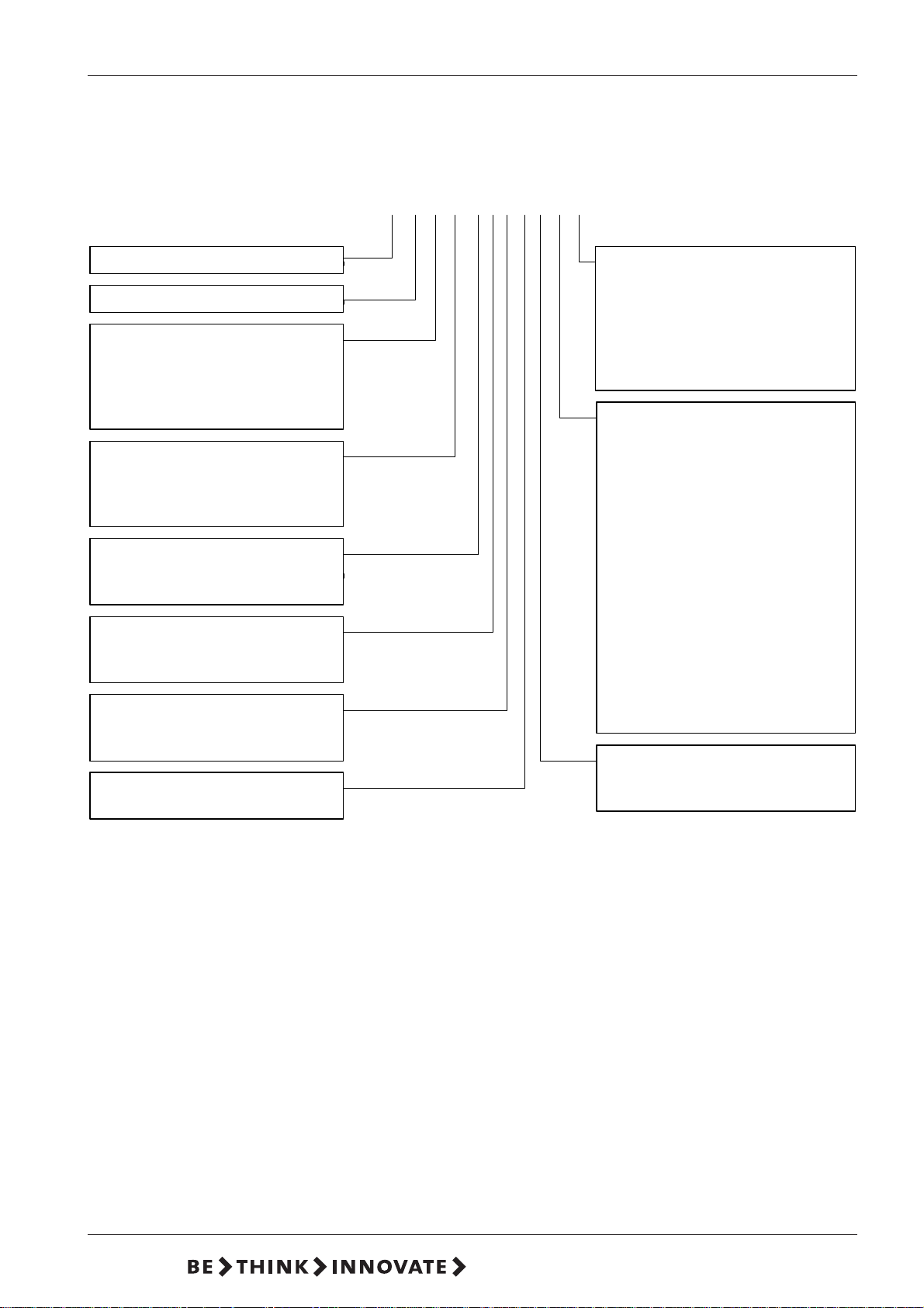
Installation Diagram
6
15.720017-V6.0
Page 7
DMX model 226 en
Type key
(Cannot be used for pump configuration.)
Example: DME 2-18 A-PP/E/C-F-3 1 1E F
Pump range D ME...
Maximum pressure [bar]
Control variant Code
Standard A
Standard + alarm relay AR
Standard + ProfIbus AP
Standard + GENIbus AG
Dosing head material Code
Polypropylene PP
PVDF PV
Stainless steel 1.4401 SS
Gasket material Code
EPDM E
FKM V
Valve ball material Code
Ceramics C
Stainless steel 1.4401 SS
Control panel Code
Front-fitted F
Side-fitted S
Voltage Code
1 x 100-240 V, 50-60 Hz 3
Code Mains plug
F EU (Schuko)
B USA, CAN
GUK
IAU
ECH
JJP
Code Connection,
suction/ discharge
1 Tubing 6/9
Tubing 4/6
supplied with the pump
2 Tubing 6/9
Tubing 6/12+ 9/12
supplied with the pum
3 Tubing 4/6
4 Tubing 6/9
5 Tubing 6/12
6 Tubing 9/12
A Threaded Rp 1/4
B Threaded Rp 3/8
E Cementing d.10
F Cem enting d. 12
Code Valves
1 Standard valve
2 Spring- loaded valve
V6.0
7
Page 8
1 Of General Interest
1.1 In General
1.2 Using this Paper
DMX model 226 en
This operation manual contains all information for safe operation of the described
product.
If you require further information or if any problems arise which are not reflected in
detail in this manual, contact Grundfos directly for the information needed.
❏ Descriptions are written as plain text.
❏ Lists are indicated by squares (❏), sublists by dashes (-).
❏ Operation steps are indicated by bullets (●), substeps by small bullets (•).
❏ Cross-references are indicated by
❏ The headings
WARNING Danger of injuries and accidents!
WARNING, CAUTION
italic letters
and
NOTE
and an arrow (➜).
have the following meaning:
!
1.3 Warranty
CAUTION Danger of incorrect operation or damage to the product!
NOTE There is an exceptional feature.
Warranty in accordance with our general terms of sale and delivery shall only be
valid, if
❏ the product is used according to the information within this paper,
❏ the product is not being opened or used improperly,
❏ maintenance and repair is implemented exclusively by authorized and
qualified personnel,
❏ original spare parts are used for repairs.
8
15.720017-V6.0
Page 9
DMX model 226 en
2 Safety Instructions
2.1 Application of the Product
!
!
The dosing pump described here is suitable for dosing liquid, non-abrasive and noninflammable media strictly complying with the instructions of this manual.
WARNING Other applications are not intended and are not
permitted. Grundfos accept no responsibility for
damages caused by unintended use.
NOTE Explosion-proof pumps are indicated on the pump type
identification label as well as on the motor type
identification label. The enclosed declaration of
conformity with the 94/9/EC guideline will replace the
declaration of EC conformity incorporated in this
instructions manual.
WARNING For the use of a pump indicated as explosion-proof for
operation in potentially explosive operating places
according to guideline 94/9/EC, please follow the
enclosed instructions "Operating an explosion-proof
pump" in addition to this instructions manual.
2.2 Obligations of the Operating Authority
The operating authority of the plant is responsible for
❏ instructing the operation personnel
❏ arranging regular maintenance
2.3 Averting Dangers
WARNING When dosing dangerous media, observe the
!
CAUTION Adjust the stroke length only while the pump is
corresponding safety precautions!
Wear protective gloves and glasses when executing
work at the dosing head, connections or lines!
Only use the prescribed line types!
Do not open the pump!
Repair only by authorized personnel!
running!
Danger of damages.
V6.0
9
Page 10
3 Technical Data
p
p
3.1 Pump Types
DMX model 226 en
Order No.
Simple pum
Double pum
DMX 24-8 DMX 24-8/24-8
DMX 52-8 DMX 52-8/25-8
DMX 100-8 DMX 100-8/ 100-8
DMX 142-8 DMX 142-8/ 142-8
DMX 37-5 DMX 37-5/37-5
DMX 82-5 DMX 82-5/82-5
DMX 160-5 DMX 160-5/ 160-5
DMX 224-5 DMX 224-5/ 224-5
DMX 60-3 DMX 60-3/60-3
DMX 130-3 DMX 130-3/ 130-3
DMX 255-3 DMX 255-3/ 255-3
DMX 380-3 DMX 380-3/ 380-3
DMX 67-10 DMX 67-10/67-10
DMX 132-10 DMX 132-10/132-10
DMX 190-10 DMX 190-10/190-10
DMX 190-8 DMX 190-8/ 190-8
DMX 95-8 DMX 95-8/95-8
DMX 199-8 DMX 199-8/ 199-8
DMX 280-8 DMX 280-8/ 280-8
DMX 280-6 DMX 280-6/ 260-6
DMX 152-6 DMX 152-6/ 152-6
DMX 321-6 DMX 321-6/ 321-6
DMX 321-4 DMX 321-4/ 321-4
DMX 460-6 DMX 460-6/ 460-6
DMX 460-3,5 D M X 460 -3 , 5 / 46 0-3,5
DMX 249-3 DMX 249-3/ 249-3
DMX 315-3 DMX 315-3/ 315-3
DMX 525-3 DMX 525-3/ 525-3
DMX 765-3 DMX 765-3/ 765-3
Dosing
head size
Motor
1
222
0,18kW
Stroke
volume
[ml]
13,8
336
1
18,5
227,8
0,37kW *
344,6
473
* with PTC thermistor: 0,55 kW
3.2 Pump Performance
3.2.1 Accuracy
Dosing flow fluctuation
Linearity deviation
10
< ± 1.5 % within the control range 1:10
± 4 % of full-scale value within control range 1:5,
direction of adjustment from maximum to minimum stroke length
These data refer to:
- dosing medium water
- fully deaerated dosing head
- measurement according to ALLDOS factory standard No. 0010/0011
- standard version of pump
15.720017-V6.0
Page 11
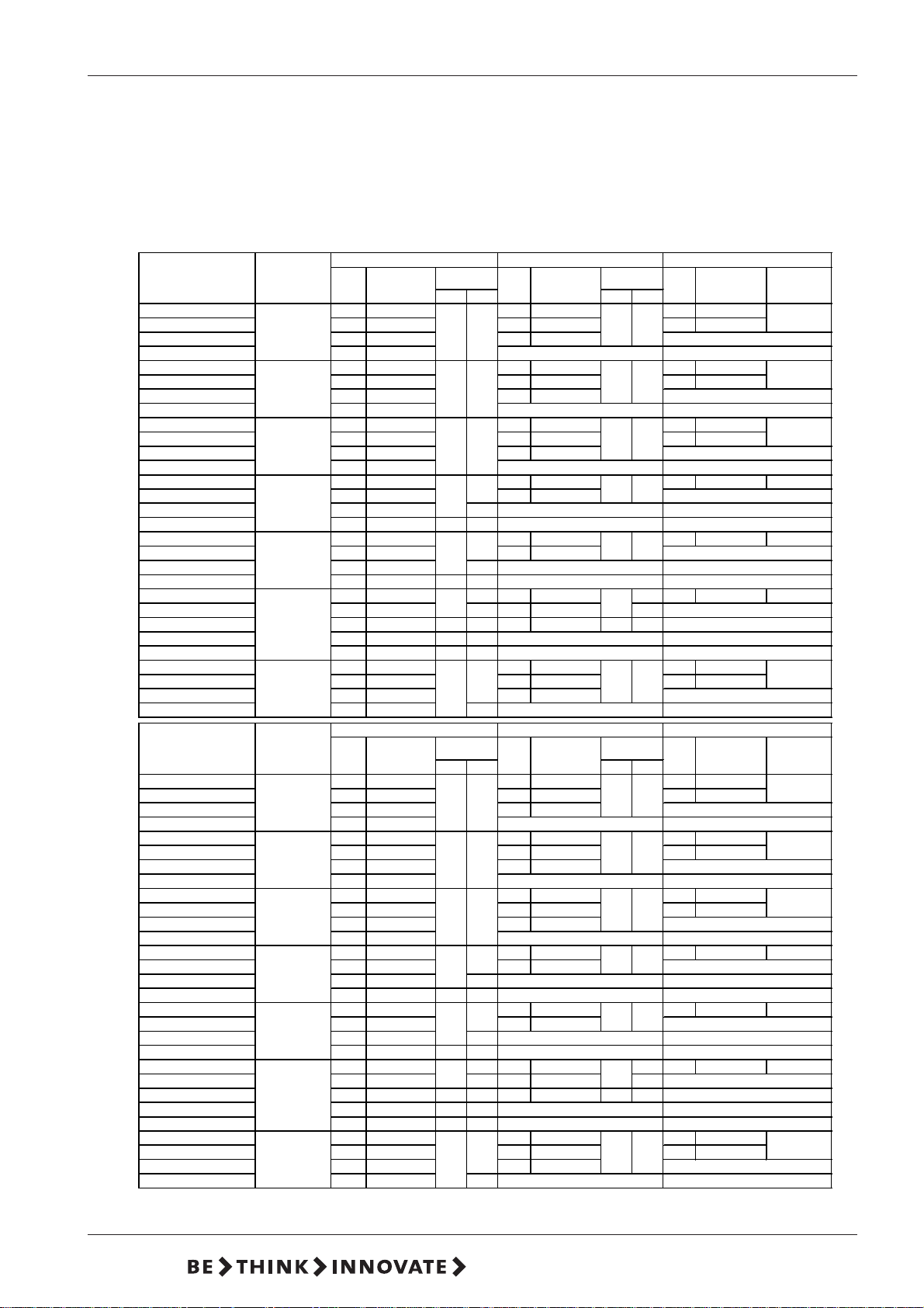
DMX model 226 en
3.2.2 Performance
The data in the following table refer to:
- maximum counterpressure
- dosing medium water
- flooded suction 0.5 m w. c.
- fully deaerated dosing head
- three-phase 400 V motor
50 Hz 60 Hz 100 Hz
Stroke
value [H/min]
3 AC 1 AC 3 AC 1 AC
Q [l/h]
Stroke
value [H/min]
p max * [bar]p max * [bar]
Q [l/h]
Stroke
value [H/min]
p max * [bar]
Simple pump
Dosing head
size
Q [l/h]
DMX 24-8 24 29 28 34,8 48 58
-
88
-
-
DMX 52-8
DMX 100-8
DMX 142-8
188
52 63 62 75,6 104 126
100 120 120 144
142 168
DMX 37-5 37 29 45 34,8 75 58
5
DMX 82-5
DMX 160-5
255
DMX 224-5 224 168
DMX 60-3
DMX 130-3
DMX 255-3
333
DMX 380-3 380 168
DMX 67-10
DMX 132-10
DMX 190-10 190 175 -
1
DMX 190-8
DMX 95-8
DMX 199-8 199 120 239 144
DMX 280-8
2
DMX 280-6
DMX 152-6
DMX 321-6 321 120 - 385 144 -
DMX 321-4
3
DMX 460-6
DMX 460-3,5 460 175 - 3,5
DMX 249-3
DMX 315-3
DMX 525-3
43
DMX 765-3 765 175 -
Double pump
Dosing head
size
DMX 24-8/24-8
DMX 52-8/25-8
DMX 100-8/100-8 200 120 240 144
188
DMX 142-8/142-8 284 168
DMX 37-5/37-5
DMX 82-5/82-5
DMX 160-5/160-5 320 120 384 144
255
DMX 224-5/224-5
DMX 60-3/60-3
DMX 130-3/130-3 260 63 312 75,6 520 126
DMX 255-3/255-3 510 120 612 144
333
DMX 380-3/380-3
DMX 67-10/67-10 134 57 161 68,4 268 114 10
DMX 132-10/132-10 264 120 317 144
DMX 190-10/190-10
1
DMX 190-8/190-8
DMX 95-8/95-8 190 57 228 68,4 380 114 8
DMX 199-8/199-8
DMX 280-8/280-8
2
DMX 280-6/260-6 560 175 - 6
DMX 152-6/152-6 304 57 6 365 68,4 6 608 114 6
DMX 321-6/321-6
DMX 321-4/321-4
3
DMX 460-6/460-6 920 175 6 -
DMX 460-3,5/460-3,5
DMX 249-3/249-3
DMX 315-3/315-3 630 72 756 86,4 1260 144
DMX 525-3/525-3 1050 120 1260 144
4
DMX 765-3/765-3
82 63 98 75,6 164 126
160 120 192 144
--
60 29 72 34,8 120 58
130 63 156 75,6 260 126
255 120 306 144
--
67 57 80 68,4 134 114 10
132 120 158 144
10 10 10
10
--
190 175 - 8
95 57 114 68,4 190 114 8
888
8
280 175 280 175 - 6
152 57 6 182 68,4 6 304 114 6
66
-
-
-
321 120 - 4 385 144 - 4
460 175 6 -
--
-
249 57 299 68,4 498 114
315 72 378 86,4 630 144
333
525 120 630 144
--
60 Hz
Stroke
value [H/min]
Q [l/h]
50 Hz
Stroke
value [H/min]
p max * [bar]
3 AC 1 AC 3 AC 1 AC
Q [l/h]
48 29 56 34,8 96 58
104 63 125 75,6 208 126
--
74 29 90 34,8 148 58
164 63 197 75,6 328 126
448 168
-
120 29 144 34,8 240 58
760 168
10 10 10
10
380 175 380 175 - 8
88
398 120 478 144
8
560 175 -
--
--
-
--
-
304 120 - 365 144 -
6
642 120 - 4 770 144 - 4
--
920 175 - 3,5
--
498 57 598 68,4 996 114
333
3
1530 175 -
--
5
33
p max * [bar]
88
55
33
8
6
Q [l/h]
100 Hz
Stroke
value [H/min]
-
-
-
-
-
-
-
-
-
-
-
p max * [bar]
-
-
-
-
-
-
-
-
-
-
-
8
5
3
3
8
5
3
3
*) maximum counterpressure
V6.0
11
Page 12
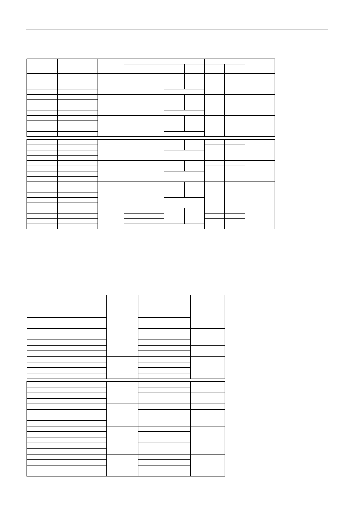
3.3 Suction heights
5
5
3.3.1 Media with a viscosity similar to water
Simple
pump
DMX 24-8 DMX 24-8/24-8
DMX 52-8 DMX 52-8/25-8
DMX 100-8 DMX 100-8/100-8
DMX 142-8 DMX 142-8/142-8
DMX 37-5 DMX 37-5/37-
DMX 82-5 DMX 82-5/82DMX 160-5 DMX 160-5/160-5
DMX 224-5 DMX 224-5/224-5
DMX 60-3 DMX 60-3/60-3
DMX 130-3 DMX 130-3/130-3
DMX 255-3 DMX 255-3/255-3
DMX 380-3 DMX 380-3/380-3
DMX 67-10 DMX 67-10/67-10
DMX 132-10 DMX 132-10/132-10
DMX 190-10 DMX 190-10/190-10
DMX 190-8 DMX 190-8/190-8
DMX 95-8 DMX 95-8/95-8
DMX 199-8 DMX 199-8/199-8
DMX 280-8 DMX 280-8/280-8
DMX 280-6 DMX 280-6/260-6
DMX 152-6 DMX 152-6/152-6
DMX 321-6 DMX 321-6/321-6
DMX 321-4 DMX 321-4/321-4
DMX 460-6 DMX 460-6/460-6
DMX 460-3,5 DMX 460-3,5/460-3,5
DMX 249-3 DMX 249-3/249-3
DMX 315-3 DMX 315-3/315-3
DMX 525-3 DMX 525-3/525-3
DMX 765-3 DMX 765-3/765-3
Data in m w. c.
these data refer to:
- counterpressure 1.5 to 3 bar
- not degassing and not abrasive media
- temperature of 20 °C
- stroke length 100%
- standard version
Double
pump
Dosing head
Suction
size
height *
1 3 m 1 m 4 m
23 m1 m
13 m1 m
23 m1 m
32 m1 m
1,5 m 1 m 1 m 0,5 m
4
1,5 m 1 m
1 m 0,5 m
0 m 0 m
DMX model 226 en
50 Hz
suction
lift **
60 Hz
Suction
height *
2,5 m
-
2,5 m 1 m
-
2 m 1 m
-
2,5 m 1 m
-
2,5 m 1 m
-
2 m 1 m
-
1 m 0,5 m
-
suction
lift **
1 m
100 Hz
Suction
height *
suction
lift **
2,5 m 1 m
--
2 m
1,5 m
2,5 m 1 m
2 m 1 m
1,5 m 1 m
1 m
--
1 m
--
-
--
--
--
-
Max. suction
line le ng th
3 m
3 m32 m1 m
4 m
3 m
3 m
2 m
*) suction line and dosing head filled (continuous operation)
With version S 01 (stronger restoring spring), the values for dosing head
size 1 are increased by 2 m, and for dosing head sizes 2 and 3 by 1 m.
**) suction line and dosing head not filled, but dosing head and
valves moistened (commissioning)
3.3.2 Suction heights for media with maximum permissible viscosity
Simple
pump
Double
pump
Dosing head
size
Stroke
value
[1/min]
Viscosity
[mPas]
DMX 24-8 DMX 24-8/24-8 29 1000
DMX 52-8 DMX 52-8/25-8 63
DMX 100-8 DMX 100-8/100-8 120
1
DMX 142-8 DMX 142-8/142-8 168
DMX 37-5 DMX 37-5/37-5 29
DMX 82-5 DMX 82-5/82-5 63
DMX 160-5 DMX 160-5/160-5 120
2
DMX 224-5 DMX 224-5/224-5 168
DMX 60-3 DMX 60-3/60-3
DMX 130-3 DMX 130-3/130-3
DMX 255-3 DMX 255-3/255-3
3
DMX 380-3 DMX 380-3/380-3
DMX 67-10 DMX 67-10/67-10
DMX 132-10 DMX 132-10/132-10 120
DMX 190-10 DMX 190-10/190-10
1
DMX 190-8 DMX 190-8/190-8
DMX 95-8 DMX 95-8/95-8
DMX 199-8 DMX 199-8/199-8
DMX 280-8 DMX 280-8/280-8
2
DMX 280-6 DMX 280-6/260-6
29 500
63 400
120 100
168 50
57 700
175
57 500 1
120 200
175 150
DMX 152-6 DMX 152-6/152-6 57
DMX 321-6 DMX 321-6/321-6
DMX 321-4 DMX 321-4/321-4
DMX 460-6 DMX 460-6/460-6
DMX 460-3,5 DMX 460-3,5/460-3,5
30
120 100
175 50
DMX 249-3 DMX 249-3/249-3 57
DMX 315-3 DMX 315-3/315-3 72
DMX 525-3 DMX 525-3/525-3 120
4
DMX 765-3 DMX 765-3/765-3 175
700
400
200 0
600
500
200
150
400
200 0
400
100
100
Suction height
50
10
[m water
gauge]
1
1
0
0
1
0
0
These data refer to:
- Newtonian liquids
- not degassing and
not abrasive media
- temperature of 20 °C
- standard version
12
15.720017-V6.0
Page 13

DMX model 226 en
3.4 Dosing Curves
The dosing curves shown here are trend curves according to the ALLDOS factory
standard No. 0010/0011
They refer to:
❏ Performance of single pump
(the flow rate is doubled for the double pump)
❏ Water as the dosing medium
❏ Zero point of pump Q
❏ Standard version of pump
3.5 Materials
Pump
Pump housing
Diaphragm flanges
Adjustment knob, front panel
Al 226
GG 25
ABS
3.6 Ambient and Operating Conditions
for specified pressure - see diagram.
0
Admissible ambient temperature
Admissible storage temperature
Admissible humidity
!
Noise level
Minimum counterpressure
Admissible temperature of dosing liquids
0 °C to +40 °C
-20 °C to + 70 °C
rel. humidity: 70% at 40 °C, 90% at 35 °C
CAUTION Danger of malfunctioning or damage!
Do not install outdoors!
WARNING Risk of hot surfaces! Pumps with A.C. motors can
become hot. Allow a minimum spacing of 100 mm to
the ventilator cowl!
± 55 dB (A), testing following DIN 45635-01-KL3
1 bar
These data refer to the pressure valve of the pump. Pressure losses along the way
to the injection point inclusively are not taken into account.
Materials up to 10 bar
PVC
1.4571
PP
PVDF
1)
0 °C - 40 °C
-10 °C - 70 °C
0 °C - 40 °C
-10 °C - 60 °C
(70 °C at 9 bar)
V6.0
1)
For SIP/CIP applications 145 °C are admissible for a short time
(approx. 15 min) at < 2 bar .
CAUTION Observe freezing and boiling point of the medium!
13
Page 14
p
p
V4A
p
V
3.7 Weight
DMX model 226 en
le pum
Sim
DMX 24-8 DMX 24-8/24-8
DMX 52-8 DMX 52-8/25-8
DMX 100- 8 DMX 100- 8 /100-8
DMX 142- 8 DMX 142- 8 /142-8
DMX 37-5 DMX 37-5/37-5
DMX 82-5 DMX 82-5/82-5
DMX 160- 5 DMX 160- 5 /160-5
DMX 224- 5 DMX 224- 5 /224-5
DMX 60-3 DMX 60-3/60-3
DMX 130- 3 DMX 130- 3 /130-3
DMX 255- 3 DMX 255- 3 /255-3
DMX 380- 3 DMX 380- 3 /380-3
DMX 67-1 0 DMX 67- 10 /67-10
DMX 132-10 DMX 132-10/132-10
DMX 190-10 DMX 190-10/190-10
DMX 190- 8 DMX 190- 8 /190-8
DMX 95-8 DMX 95-8/95-8
DMX 199- 8 DMX 199- 8 /199-8
DMX 280- 8 DMX 280- 8 /280-8
DMX 280- 6 DMX 280- 6 /260-6
DMX 152- 6 DMX 152- 6 /152-6
DMX 321- 6 DMX 321- 6 /321-6
DMX 321- 4 DMX 321- 4 /321-4
DMX 460- 6 DMX 460- 6 /460-6
DMX 460- 3,5 DMX 460- 3,5 / 460 -3, 5
DMX 249- 3 DMX 249- 3 /249-3
DMX 315- 3 DMX 315- 3 /315-3
DMX 525- 3 DMX 525- 3 /525-3
DMX 765- 3 DMX 765- 3 /765-3
Weight Weight
PVC
Approx. 15 kg Approx. 21 kg Approx. 24 kg Approx. 36 kg
Approx. 21 kg Approx. 30 kg Approx. 30 kg Approx. 48 kg
Double pum
PVC
4A
14
15.720017-V6.0
Page 15

DMX model 226 en
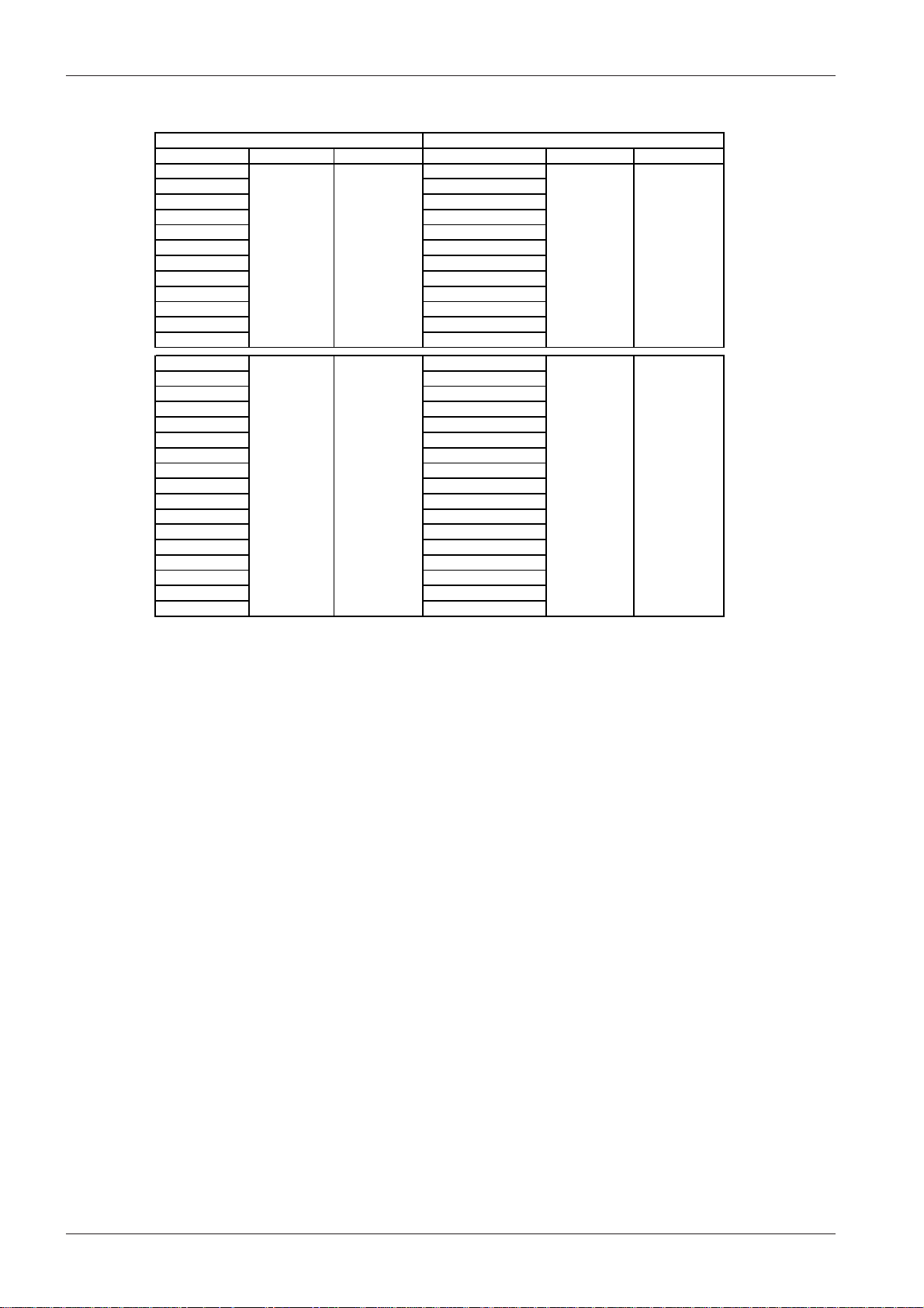
3.8 Dimensional Drawing
DM X 24-8
DM X 52-8
DM X 100-8
DM X 142-8
DM X 37-5
DM X 82-5
DM X 160-5
DM X 224-5
DM X 60-3
DM X 130-3
DM X 255-3
DM X 380-3
abcdefghik l m n prrxs
302 178 152
310
302 310
302
97,5
310
Values in brackets with Ex motor
V6.0
85,597,5
190 118 180 180
190 188 152 85,5 425 208
425 208 104,5
85,5 425 208 106,5 250 (315) 4 G 11/4" 118 180 180 19897,5 190 208 152
250 (315) 4 198
104,5
250 (315) 4 G 11/4" 118 180 180 198
G 11/4"
15
Page 16

DMX model 226 en
DM X 67-10
DMX 132-10
DMX 190-10
DM X 190-8
DM X 95-8
DM X 199-8
DM X 280-8
DM X 280-6
DM X 152-6
DM X 321-6
DM X 321-4
DM X 460-6
DM X 460-3,5
DM X 249-3
DM X 315-3
DM X 525-3
DM X 765-3
16
abcde fghik l m n prrxs
380 136 222 178 140 123 440 208 80 233 (352) 34 G 11/4" 160 190 258 223
372
136 222 188 140 123 444 208 80 233 (352) 29 G 11/4" 160 190 258 223
372
380
136 222 208 140 123 453 208 83 258 223233 (352) 19 G 11/4" 160 190
372
380
136 222 240 140 258 -233 (352) 3 G 2" 160 190123 498 208 92
390
389
15.720017-V6.0
Page 17

DMX model 226 en
4 Installation
4.1 Installation Information
Picture of optimal installation:
8
1 Dosing tank
2
9
7
2 Electric agitator
3 Extraction device
10
6
4 Suction pulsation damper
5 Dosing pump
6 Overflow valve
1
4
3
5
7 Pressure retention valve
8 Pulsation damper
9 Measuring glass
10 Injection unit
11
12
For easy deaeration of the pump:
● Install a ball valve (11) with bypass line (back to the dosing tank)
immediately behind the pressure valve
In case of long pressure lines:
● Install a check-back valve (12) into the dosing line.
V6.0
● Keep the suction line as short as possible, avoid a tangled suction
line
• If necessary, use swept bends instead of elbows.
● Always lay the suction line rising to the suction valve of the dosing
pump.
• Avoid loops which cause air bubbles.
p
10
6
● For non-degassing media with viscosity similar to water, the pump can
be mounted onto the tank (observe the admissible suction height).
Preferably flooded suction.
For dosing media which tend to sedimentation:
● Install a suction line with filter (13) in a way ensuring that the suction
13
valve remains several centimetres a bove the botton of the tank.
6 Overflow valve
10 Injection unit
17
Page 18

DMX model 226 en
4
● In dosing systems that require a long suction line:
Provide a properly dimensioned pulsation damper (4) directly in front of the
suction valve of the dosing pump.
8
● Note for pressure side installation:
to protect the piping use pulsations damper (8) for rigid piping longer than
3m and tubing longer than 5m.
p
6
10
● For outgassing and viscous media: flooded suction
● To protect the dosing pump and the pressure line agains: excessive
development of pressure: Install an overflow valve (6) in the pressure line.
10 Injection unit
7
p≥ 2 bar
● With open outflow of the dosing medium or a counterpressure below 1 bar:
Install a pressure retention valve (7) directly in front of the outlet or the
injection unit.
A positive pressure difference of at least 1 bar has to exist between the
counterpressure at the injection point and the pressure of the dosing medium
at the suction valve of the dosing pump. If this cannot be guaranteed:
• Install a pressure retention valve (7) in the pressure line
p
1
p2 - p
1
1 bar
_
>
To avoid the siphon effect:
p
● Install a pressure retention valve in the dosing line and, if
2
necessary, a solenoid valve (14) in the suction line.
14
18
WARNING Risk of hot surfaces! Pumps with A.C. motors can
!
become hot. Allow a minimum spacing of 100 mm to
the ventilator cowl!
15.720017-V6.0
Page 19

DMX model 226 en
4.2 Transport and Storage
● Handle with care, do not throw!
❏ Dry and cool storage place.
❏ Take heed of upright position of the dosing pump when storing it, so that
gear grease can not leak out.
CAUTION Observe permissible storing temperature!
4.3 Mounting
● Mount the pump horizontally with 4 screws M8 on the tank or on a console.
● Replace the screw plugs by the attached venting screws.
4.4 Connecting the Suction and Pressure Lines
WARNING All lines must be stress-free!
!
Only use the prescribed line types!
B
A
C
A: Suction valve C: Pipe connection
B: Discharge valve D: Tube connection (only DN20)
● Connect the suction line to the suction valve (A).
• The foot valve must keep a distance of ca. 10 cm to the bottom of the
container.
● Connect the pressure line to the pressure valve (B).
D
V6.0
19
Page 20

4.5 Electrical Connections
4.5.1 Versions with mains plug
4.5.2 Versions without mains plug
DMX model 226 en
WARNING Prior to the mains connection check if the voltage
!
NOTE The pump is being switched by switching the mains
● Connect the mains plug to a mains socket.
● Connect the motor according to the terminal connection diagram (stamped in
the clamp box).
CAUTION Observe the sense of rotation!
indicated on the type plate corresponds with the local
voltage!
Switch off mains before connecting!
No changes at the mains cable and the mains plug may
be done!
voltage.
Do not switch on the mains until the pump should be
started.
A motor protector, adjusted to nominal motor current,
must be installed by the customer.
For use with a frequency converter the jumpers in the
clamp box have to be set according to the converter
voltage.
In the state of delivery, the jumpers of 3-phase motors
are set for star connection.
20
15.720017-V6.0
Page 21

DMX model 226 en
5 Commissioning
5.1 Inspections before Commissioning
● Check the tightness of all connections. If necessary, retighten.
● Check the correctness of all electrical connections.
● Check if the voltage indicated on the type plate corresponds with the local
voltage!
5.2 Commissioning
CAUTION After initial start-up and after each diaphragm
● Open the shut-off valves (15, 16, if installed) both at the suction and
pressure side.
● Open the deaeration valve (17, if installed) of the dosing line, or remove
pressure on the pressure side so that the medium is able to issue without
counterpressure.
● Switch on mains voltage.
● Set the stroke length adjustment knob to 100%.
Keep the dosing pump in operation until bubble-free medium comes out of the
deaeration valve or the dosing line.
● Close the deaeration valve (17, if installed).
The pump is now ready for operation.
exchange, tighten the fixing screws of the dosing
head:
After approx. 6 to 10 working hours or two
days, tighten the dosing head screws crosswise using
a torque wrench, torque 6 Nm.
15
1617
V6.0
21
Page 22

6 Operation
6.1 Description of the Device
DMX model 226 en
1
2
47
3
9
5
6
1 Motor
2 Gears
3 Eccentric
4 Dosing diaphragm
5 Dosing head
6 Suction valve
7 Pressure valve
8 Stroke length adjustment knob
9 Hall sensor
Principle of function
❏ Reciprocating displacement pump with electric motor and mechanical
diaphragm guide
.
❏ The rotation of the motor is transformed into the reciprocating movement of
the dosing diaphragm by the eccentric and the tappet.
❏ Adjustment of the dosing flow is possible by adjusting the stroke length of
the tappet.
8
6.2 Switching on / off
6.2.1 Switching on
6.2.2 Switching off
22
● Switch on the mains power.
● Switch off the mains power.
15.720017-V6.0
Page 23

DMX model 226 en
6.3 Adjusting the Dosing Flow by Means of the Stroke length
CAUTION Adjust the stroke length only while the pump is
running!
Danger of damages.
5
6
0
7
0
8
0
9
0
100
%
4
0
0
3
0
2
0
1
0
0
● Loosen the locking screw (A) on the stroke length adjustment knob (8) a little
using a screwdriver.
● Increasing the dosing flow: Turn the stroke adjustment knob slowly to the left
until the desired dosing flow is reached.
● Decreasing the dosing flow: Turn the stroke adjustment knob slowly to the
right until the desired dosing flow is reached.
● Gently tighten the locking screw (A) again using a screwdriver.
8
A
6.4 Adjusting the Stroke Length Adjustment
WARNING Wear protective gloves and glasses when executing
!
CAUTION Adjust the stroke length only while the pump is
work at the dosing head, connections or lines!
running!
Danger of damages.
The zero point (no dosing) of the dosing pump is adjusted in the works at a
counterpressure of 3 bar (see dosing curves).
If the operational counterpressure at the injection point is considerably above or
below this value, it is advisable to readjust the zero point to obtain more precise
values of the dosing output.
● Install a graduated tube at the suction valve.
If this is not present:
• insert the suction line into a graduated measuring jug.
● Start the dosing pump and adjust the dosing flow to 15%.
For pumps with tank empty indication:
• Remove the plug of the tank empty indication.
● Completely unscrew the locking screw (A) on the stroke length adjustment
knob (1) using a screwdriver.
● Turn the adjustment knob slowly clockwise until the dosage stops in the
measuring jug or tube.
● Remove the plug with a small screw driver without changing the position of
the adjustment knob and unscrew the cheese head screw together with the
flat spiral spring.
● Fit the adjustment knob on the adjusting spindle so that the zero line on the
scale and the mark on the adjustment knob coincide.
● Screw in the cheese head screw and the spiral spring until the spring is
preloaded but does not block. Even when adjusted to 100% the spring of the
adjustment knob must still remain preloaded.
● Screw in the locking screw (A) again using a screwdriver, and tighten gently.
V6.0
23
Page 24

6.5 Possible Failures
g
p
play
y
g
gg
y
g
y
A
j
y
y
quip
g
g
p
p
p
g
p
)
y
p
g
p
y)
g
Failure Cause Correction
Not connected to mains Connect the mains line
Wron
mains voltage Replace the dosing pum
Electrical failure Return the dosing pump to the works for repair
DMX model 226 en
Dosing pump does not run
Dosing pump does not suck in
Dosing pump does not dose
Dosing output of the pump
inaccurate
The empty indication has responded. The
empty indication symbol blinks in the display
The diaphragm breakage indication has
responded. ERROR and MBS are blinking in
the dis
Leak
Cross-section of the suction line too narrow or
or suction line too lon
Clo
Foot valve covered b
Buckled suction line Lay the suction line correctly, check for
Cr
Diaphragm broken or diaphragm tappet torn
out
ir in the suction line and dosing head Wait, until the pump has deaerated
Stroke ad
Medium too viscous or densit
Cr
Valves not correctly assembled Assemble the valve inside parts in the right
Injection point blocked Check and possibly correct the flow direction,
Inexpert installation of lines and peripheral
e
Dosin
De
Valves
Zero-point misadjusted Adjust the zero-point to the actual back
Fluctuations of back pressure Application of a pressure retention valve and a
Fluctuations of suction hei
Siphon effect (admission pressure higher than
back
Leak
Parts in contact with media not resistant Re
Dosing diaphragm worn out (incipient tears) Replace the diaphragm, also observe
Fluctuations of mains volta
Variation of the dosing medium (density,
viscosit
.
suction line Exchange or seal the suction line
ed suction line Rinse or replace the suction line
sediment Suspend the suction line at a higher position
stalline deposits in the valves Clean the valves
ustment set to zero Turn the adjustment knob in the "+" direction
too high Check the installation
stalline deposits in the valves Clean the valves
ment
head not fully deaerated Repeat deaeration
assing medium Check the installation
artially soiled or incrusted Clean the valves
ht Keep the suction level constant
ressure
or porous suction line or pressure line Replace the suction line or pressure line
e Decrease the back pressure of the pum
Remove the cause
Replace the diaphragm.
Check with specification of Grundfos
e
dama
Exchange the diaphragm
order and check or possibly correct the flow
direction
or remove the occlusion
Check for perviousness and correct installation
ressure
ulsation damper
Install a pressure retention valve
lace with resistant materials
maintenance instructions
Examine the concentration, possibly employ an
itator
a
24
15.720017-V6.0
Page 25

DMX model 226 en
7 Operation with Other Electronics
CAUTION First refer to the general Section 6 "Operation". This
7.1 Electronics Version Stroke sensor
Pump type with inductive proximity switch of two-wire design according to NAMUR
DIN 19 234for signalling the strokes.
The sensor can be installed in potentially explosive atmospheres if PTB-approved
isolating switching amplifiers with an intrinsically-safe control circuit [EExia] or
[EExib] are connected. The sensor can be used up to zone 1 depending on the
isolating amplifier. The specifications on the conformity certificate for the isolating
amplifier must be observed.
Supply voltage U
B
7.2 Electronics Diaphragm Breakage Sensor
7.2.1 Technical Data of the Electronics
7.7 ... 10 V
Section 7 "Operation with Other Electronics" only
describes the additional functions.
Contact load
Power consumption
Degree of protection
Permissible temperature range
250 V / 6 A, max. 550VA
1.15 VA
IP 65
0 - 40 °C
7.2.2 Dimensional Drawing (Electronics Enclosure)
80
63.5
Description
Model 230 V (+10% /-10%)
Model 115 V (+10% /-10%)
130
113.5
V6.0
25
Page 26

7.2.3 Function
Pumps prepared for a diaphragm breakage indication:
❏ Special dosing head flange for inserting the optoelectronic sensor
❏ Optoelectronic sensor, contains
- infrared sender
- infrared receiver
In case of a leaking diaphragm:
❏ Dosing liquid penetrates the dosing head flange.
- The light refraction will be changed.
❏ The sensor produces a signal.
- The electronics switches two contacts which can be used e. g. for
7.2.4 Electrical Connections of the Electronics
WARNING Electrical connections only by qualified personnel!
!
DMX model 226 en
triggering an alarm device or switching off the pump.
Switch off mains before connecting!
Observe the local safety regulations!
Protect the cable connections and plugs from
corrosion and moisture.
CAUTION Before connecting the power supply cable:
Check that the supply voltage specified on the rating
plate agrees with the local voltage. An incorrect power
supply could destroy the unit!
To guarantee electromagnetic compatibility (EMC):
The input cables and current output cables must be
shielded.
•
Connect shield at one end to PE.
➜
Refer to the connection diagram!
Route input cables, current output cables and power
supply cables in separate ducts.
● Connect the device to the mains according to the connection chart.
● Connect the electronics with the sensor according to the connection chart.
WARNING The potential-loaded contact 1, terminals 6 and 7, is
!
loaded with mains voltage.
Switch off mains before connecting contact 1!
26
CAUTION The contacts have no protective circuits. Only pure
ohmic loads may be switched. For switching the pump
motor, a contactor has to be connected inbetween.
● Connect contacts 1 and 2 according to individual needs.
➜
Refer to Section "Electrical connections"
15.720017-V6.0
Page 27

DMX model 226 en
7.2.5 Relay Outputs
NOTE The relay output connection depends on the
application and the connected actuators.
Interference suppression is required for inductive loads (also relays and contactors).
If this is not possible, protect the relay contacts using a suppressor circuit as
described below.
R
❏ With AC voltage:
Current up to Capacitor C Resistor R
C
60 mA 10 nF 260 V 390 Ω 2 W
70 mA 47 nF 260 V 22 Ω 2 W
150 mA 100 nF 260 V 47 Ω 2 W
1.0 A 220 nF 260 V 47 Ω 2 W
+
❏ With DC voltage: connect freewheeling diode parallel to relay or contactor.
CAUTION Provide relay outputs on site with an appropriate
backup fuse!
NOTE These connections depend on the type of actuator
used, and should only be understood as guidelines.
➜
Refer to actuator documentation.
-
S1
S2
K1LK2NK3PEK4PEK5NK6 K7 K8 K9 K10
230 V AC /
115 V AC
contakt 1
(non-floating
230 V AC / 115 V AC)
contakt 2 (floating) sensor
7.2.6 Screwing the Sensor into the Dosing Head
● Screw in the sensor from the lower side into the hole of the dosing head
flange (M14 x 1.5).
❏ Now the diaphragm breakage indication is ready for start-up.
1
111111111111
green yellow white
V6.0
27
Page 28

7.2.7 Commissioning
CAUTION Carry out a functional check before commissioning!
Functional Check
● Dip the sensor into water
- Green LED and red LED are lighting:
Sensor and electronics are ready for operation!
- One or more LED do not light:
Sensor or electronics are defective!
• Call Grundfos service.
● Carefully dry the senor.
- Only the green LED still lights:
Sensor and electronics are ready for operation!
- the red LED still lights:
Sensor or electronics are defective!
• Call Grundfos service.
WARNING Do not open electronics or sensor!
!
Repair only by authorized qualified personnel.
DMX model 226 en
7.2.8 Using the Contacts
7.2.9 Description of the Device
❏ Terminals 6 and 7 (potential-loaded):
- e. g. for switching off the dosing pump in case of a diaphragm breakage
➜
Observe Technical Information of the dosing pump!
❏ Terminals 8, 9 and 10 (potential-free):
- e. g. for triggering an alarm device
There are two light-emitting diodes (LED) at the electronics.
❏ Green LED:
- Shows the readiness for operation of the system.
- It only lights when the sensor is connected to the electronics. If it does
not light in this case, either the sensor or the cable is defective or wrongly
connected.
❏ Red LED:
- Lights in case of a diaphragm breakage being detected.
- The green LED continues lighting.
28
15.720017-V6.0
Page 29

DMX model 226 en
7.2.10Maintenance
WARNING Do not open electronics or sensor!
!
❏ Sensor
• Clean it in case of malfunction.
• If it still does not operate correctly:
Replace sensor.
Description
Optosensor with 3 m cable
❏ Electronics
- No maintenance possible by the user.
• If it does not operate correctly:
Call Grundfos service.
WARNING Repair only by authorized qualified personnel.
Repair only by authorized qualified personnel.
!
V6.0
29
Page 30

8 Integral Overflow Valve
8.1 Function
8.2 Permissible Media
!
8.3 Connections
DMX model 226 en
The integral overflow valve (option) protects the complete pressure side of the
dosing line system from an impermissibly high buildup of pressure.
The valve opens if the pressure rises above its set opening pressure, and the dosing
medium can return to the solution tank.
In contrast to series-connected overflow valves, the integral valve also provides
pump protection if the pressure valve is contaminated or blocked.
WARNING Dosing heads with integral overflow valve must not be
used for abrasive or crystallizing media.
B
C
A
● Connect suction line to suction valve (A).
● Connect pressure line to pressure valve (B).
● Connect overflow line to overflow valve (C) and allow to flow by gravity into
the tank or to an appropriate overflow.
WARNING Danger of injury! Never use the pump if the line is not
!
correctly connected to the overflow valve.
30
15.720017-V6.0
Page 31

DMX model 226 en
8.4 Setting of Opening Pressure
8.4.1 General
!
!
!
The opening pressure can only be set if a manometer is installed in the system
between the pump and the next shut-off valve or pressure retention valve.
WARNING Settings on the overflow valve must only be carried out
by authorized specialists!
The opening pressure of the overflow valve is set in the factory to the maximum
pump back-pressure specified in the technical data. The opening pressure during
operation depends on various factors, e.g. the flow, the stroke frequency of the
pump, or the back-pressure. If an exact setting is required, the overflow valve must
be adapted to the local conditions.
The opening pressure must only be set to values below the maximum permissible
operating pressure.
WARNING Danger of injury! Never set the opening pressure
higher than the maximum permissible operating
pressure of the dosing system and dosing pump.
WARNING When dosing dangerous media, always refer to the
corresponding safety data sheets!
Wear protective clothing (goggles, gloves) when
working on the connections and lines!
8.4.2 Setting Instructions for Opening Pressure
Proceed as follows if the factory-set pressure is to be changed:
With the pump running
● Remove the cap from the top part of the overflow valve.
● Close the shut-off valve downstream of the manometer.
● When overflowing of the dosing medium is heard, read the current opening
pressure on the manometer.
● Using pointed pliers, rotate
- in the clockwise direction to increase the pressure or
- in the counterclockwise direction to reduce the pressure
until the desired opening pressure is set.
● Open the shut-off valve downstream of the manometer.
● Attach the cap again.
V6.0
31
Page 32

8.5 Venting
(
)
g
g
(
)
g
A
8.6 Possible Faults
Fault Cause Elimination
Permanent output from
overflow valve
No output from overflow valve
DMX model 226 en
The overflow valve can also be opened manually, thus serving as a venting valve
at the same time.
If manual venting is required (e.g. when commissioning or when the tank has been
replaced):
● Rotate the knob such that the smaller cut-out rests on the nub of the dosing
head (the rotary knob is then further away from the dosing head, the valve
B
spring is unloaded (position B).
● Once the pump has been completely vented, rotate the knob back into the
position "Operation" (position A).
A Operation
B Venting
Overflow valve set incorrectly
too low
Diaphra
m faulty Replace diaphragm
Set overflow valve to a higher
openin
pressure
Contamination Clean overflow valve
Overflow valve set incorrectly
too high
Set overflow valve to a lower
openin
pressure
8.7 Maintenance
WARNING When dosing dangerous media, always refer to the
!
8.7.1 Intervals for Cleaning and Maintenance
Clean the overflow valve, and replace the diaphragm if necessary
❏ at least every 12 months or after 8000 operating hours or
❏ should faults occur.
8.7.2 Replacing the Diaphragm
● Shut down the dosing system.
● Make it impossible for a return flow or overpressure to occur.
● Loosen the 4 screws on the top part of the overflow valve.
● Remove top part of overflow valve.
● Remove the diaphragm.
● Insert new diaphragm.
● Return top part of overflow valve and tighten screws diagonally.
Max. torque 6 Nm.
● Start up the dosing system again.
● Tighten the screws on the top part of the overflow valve again after 48 hours
of operation. Max. torque 6 Nm.
corresponding safety data sheets!
Wear protective clothing (goggles, gloves) when
working on the connections and lines!
Maintenance must only be carried out by authorized
specialists!
32
15.720017-V6.0
Page 33

DMX model 226 en
9 Maintenance
!
9.1 Replacing the Gear Grease
!
WARNING When dosing dangerous media, observe the
corresponding safety precautions!
Wear protective gloves and glasses when executing
work at the dosing head, connections or lines!
Do not open the pump!
Repair only by authorized personnel!
Switch off the pump and disconnect from mains before
doing maintenance and repair!
WARNING The gear grease may only be changed by authorized,
qualified personnel. For this purpose send the pump to
the factory.
To guarantee fault-free operation, it is recommended to have the gear grease
exchanged after 5 years or after 20000 operation hours.
9.2 Rates for cleaning and maintenance
❏ Regularly every 12 months or after 4000 operation hours, or
❏ in case of malfunction
Clean the diaphragm and valves, or replace if necessary (with stainless steel
valves: internal components). -> see spare parts
9.3 Cleaning the Suction and Pressure Valves
DN 20
optionaloptional
WARNING Wear protective gloves and glasses when executing
!
If the pump loses capacity, clean the suction and pressure valves as follows:
● Unscrew the valve
● Unscrew the screw part or the
● Clean all parts, replace faulty parts by new ones.
● Re-assemble the valve.
● Replace the O-rings by new ones, and place the valve. Observe the direction
arrow.
CAUTION Take heed that the O-ring is fitted exactly into the
work at the dosing head, connections or lines!
valve seat with round pliers.
provided groove.
V6.0
CAUTION Observe the flow direction (indicated by an arrow)!
Tighten the valves only by hand. Danger of damage!
33
Page 34

9.4 Exchanging the Diaphragm
!
DMX model 226 en
WARNING Wear protective gloves and glasses when carrying out
work on the dosing head, connections or lines!
CAUTION Adjust the stroke length only while the pump is
running!
Danger of damage.
● While pump is running set the stroke length adjustment knob to 100%.
● Switch off pump and disconnect from power supply.
● Loosen the 6 dosing head screws.
● Remove the dosing head.
● Turn the fan blades until the diaphragm reaches the front dead center
(diaphragm detaches itself from diaphragm flange).
● Unscrew the diaphragm by manually turning it to the left.
● If necessary, place the O-ring, intermediate ring and support disk.
● Screw in the new diaphragm completely, then rotate back until the holes in
the diaphragm and flange coincide.
● Turn the fan blades until the diaphragm reaches the bottom dead center
(diaphragm is pulled onto the diaphragm flange).
● Place the dosing head carefully and tighten the screws crosswise.
Max. torque: 6 Nm.
● Deaerate the dosing pump and commission it.
CAUTION After initial start-up and after each diaphragm
exchange, tighten the fixing screws of the dosing
head:
After approx. 6 to 10 working hours or two
days, tighten the dosing head screws crosswise using
a torque wrench, torque 6 Nm.
34
15.720017-V6.0
Page 35

DMX model 226
A. Appendix Dosing Curves
en:
Q = flow rate
h = stroke length
V6.0
35
Page 36

DMX model 226
DMX 24-8 (50Hz) Q0 = 3bar
30
Q [l/h]
25
20
15
10
5
0
0 102030405060708090100
DMX 52-8 (50Hz) Q0 = 3bar
70
Q [l/h]
60
50
40
30
20
10
0
0 102030405060708090100
8bar
3bar
8bar
3bar
h [%]
h [%]
DMX 24-8 (60Hz) Q0 = 3bar
30
Q [l/h]
25
20
15
10
5
0
0 102030405060708090100
DMX 52-8 (60Hz) Q0 = 3bar
70
Q [l/h]
60
50
40
30
20
10
0
0 102030405060708090100
8bar
3bar
h [%]
8bar
3bar
h [%]
Q [l/h]
Q [l/h]
DMX 100-8 (50Hz) Q0 = 3bar
140
120
100
80
60
40
20
8bar
3bar
0
0 102030405060708090100
DMX 142-8 (50Hz) Q0 = 3bar
180
160
140
120
100
80
60
40
20
0
3bar
8bar
0 102030405060708090100
h [%]
h [%]
Q [l/h]
Q [l/h]
DMX 100-8 (60Hz) Q0 = 3bar
140
120
100
80
60
40
20
8bar
3bar
0
0 102030405060708090100
DMX 37-5 (50Hz) Q0 = 3bar
50
45
40
35
30
25
20
15
10
5
0
1,5bar
4bar
0 102030405060708090100
h [%]
h [%]
36
15.720017-V6.0
Page 37

DMX model 226
Q [l/h]
Q [l/h]
DMX 37-5 (60Hz) Q0 = 3bar
50
45
40
35
30
25
20
15
10
5
1,5bar
4bar
0
0 102030405060708090100
DMX 82-5 (60Hz) Q0 = 3bar
120
100
80
60
40
20
1,5bar
4bar
0
0 102030405060708090100
h [%]
h [%]
Q [l/h]
Q [l/h]
DMX 82-5 (50Hz) Q0 = 3bar
120
100
80
60
40
20
1,5bar
4bar
0
0 102030405060708090100
DMX 160-5 (50Hz) Q0 = 3bar
200
160
120
80
40
0
1,5bar
4bar
0 102030405060708090100
h [%]
h [%]
Q [l/h]
Q [l/h]
DMX 160-5 (60Hz) Q0 = 3bar
200
160
120
80
40
1,5b ar
4bar
0
0 102030405060708090100
DMX 60-3 (50Hz) Q0 = 3bar
100
90
80
70
60
50
40
30
20
10
1,5bar
3bar
0
0 102030405060708090100
h [%]
h [%]
Q [l/h]
Q [l/h]
DMX 224-5 (50Hz) Q0 = 3bar
300
200
100
1,5bar
4bar
0
0 102030405060708090100
DMX 60-3 (50Hz) Q0 = 3bar
100
90
80
70
60
50
40
30
20
10
1,5b ar
3bar
0
0 102030405060708090100
h [%]
h [%]
V6.0
37
Page 38

DMX model 226
Q [l/h]
Q [l/h]
DMX 130-3 (50Hz) Q0 = 3bar
180
160
140
120
100
80
60
40
20
1,5b ar
3bar
0
0 102030405060708090100
DMX 255-3 (50Hz) Q0 = 3bar
350
300
250
200
150
100
50
1,5bar
3bar
0
0 102030405060708090100
h [%]
h [%]
Q [l/h]
Q [l/h]
DMX 130-3 (60Hz) Q0 = 3bar
180
160
140
120
100
80
60
40
20
p = 1,5bar
p = 3bar
0
0 102030405060708090100
DMX 255-3 (60Hz) Q0 = 3bar
350
300
250
200
150
100
50
1,5b ar
3bar
0
0 102030405060708090100
h [%]
h [%]
Q [l/h]
Q [l/h]
DMX 380-3 (50Hz) Q0 = 3bar
400
300
200
100
1,5bar
3bar
0
0 102030405060708090100
DMX 67-10 (60Hz) Q0 = 3bar
100
80
60
40
20
1,5bar
4bar
0
0 102030405060708090100
h [%]
h [%]
Q [l/h]
Q [l/h]
DMX 67-10 (50Hz) Q0 = 3bar
100
80
60
40
20
3bar
10bar
0
0 102030405060708090100
DMX 132-10 (50Hz) Q0 = 3bar
180
160
140
120
100
80
60
40
20
3bar
10bar
0
0 102030405060708090100
h [%]
h [%]
38
15.720017-V6.0
Page 39

DMX model 226
180
Q [l/h]
160
140
120
100
80
60
40
20
0
0 102030405060708090100
280
Q [l/h]
240
200
160
120
80
40
0
0 102030405060708090100
DMX 132-10 (60Hz) Q0 = 3bar
DMX 199-8 (50Hz) Q0 = 3bar
10bar
3bar
3bar
6bar
8bar
h [%]
h [%]
Q [l/h]
Q [l/h]
Q [l/h]
Q [l/h]
Q [l/h]
DMX 280-8 (50Hz) Q0 = 3bar
DMX 95-8 (50Hz) Q0 = 3bar
DMX 199-8 (60Hz) Q0 = 3bar
DMX 190-10 (50Hz) Q0 = 3bar
DMX 199-8 (50Hz) Q0 = 3bar
220
360
140
280
280
200
320
120
180
240
240
280
160
100
200
240
200
140
80
200
120
160
160
100
160
60
120
120
80
120
40
60
80
80
80
40
20
40
40
40
20
0
0
0
0
0
0 102030405060708090100
0 102030405060708090100
0 102030405060708090100
0 102030405060708090100
0 102030405060708090100
Q [l/h]
140
120
100
80
60
40
20
0
DMX 95-8 (60Hz) Q0 = 3bar
6bar
6bar
3bar
3bar
6bar
3bar
3bar
10bar
6bar
3bar
8bar
8bar
8bar
8bar
1,5bar
0 102030405060708090100
h [%]
h [%]
h [%]
h [%]
h [%]
3bar
6bar
8bar
h [%]
V6.0
39
Page 40

DMX model 226
Q [l/h]
Q [l/h]
DMX 280-6 (50Hz) Q0 = 3bar
360
320
280
240
200
160
120
80
40
6bar
3bar
0
0 102030405060708090100
DMX 152-6 (60Hz) Q0 = 3bar
220
200
180
160
140
120
100
80
60
40
20
0
3bar
1,5bar
6bar
0 102030405060708090100
h [%]
h [%]
Q [l/h]
Q [l/h]
DMX 152-6 (50Hz) Q0 = 3bar
180
160
140
120
100
80
60
40
20
3bar
6bar
1,5bar
0
0 102030405060708090100
DMX 321-6 (50Hz) Q0 = 3bar
500
400
300
200
100
3bar
6bar
0
0 102030405060708090100
h [%]
h [%]
Q [l/h]
DMX 321-6 (60Hz) Q0 = 3bar
500
400
300
200
100
3bar
6bar
0
0 102030405060708090100
h [%]
DMX 321-4 (50Hz) Q0 = 3bar
500
Q [l/h]
400
300
200
100
0
0 102030405060708090100
DMX 460-6 (50Hz) Q0 = 3bar
600
Q [l/h]
500
400
300
200
100
0
0 102030405060708090100
3bar
h [%]
6bar
3bar
h [%]
40
15.720017-V6.0
Page 41

DMX model 226
600
Q [l/h]
500
400
300
200
100
Q [l/h]
DMX 460-3,5 (50Hz) Q0 = 3bar
3bar
0
0 102030405060708090100
h [%]
DMX 249-3 (60Hz) Q0 = 3bar
320
280
240
200
160
120
80
40
3bar
1,5bar
0
0 102030405060708090100
h [%]
Q [l/h]
Q [l/h]
DMX 249-3 (50Hz) Q0 = 3bar
320
280
240
200
160
120
80
40
3bar
1,5bar
0
0 102030405060708090100
DMX 315-3 (50Hz) Q0 = 3bar
500
400
300
200
100
3bar
1,5bar
0
0 102030405060708090100
h [%]
h [%]
Q [l/h]
Q [l/h]
DMX 315-3 (60Hz) Q0 = 3bar
500
400
300
200
100
3bar
1,5bar
0
0 102030405060708090100
DMX 525-3 (60Hz) Q0 = 3bar
800
600
400
200
3bar
1,5bar
0
0 102030405060708090100
h [%]
h [%]
Q [l/h]
Q [l/h]
DMX 525-3 (50Hz) Q0 = 3bar
800
600
400
200
3bar
1,5bar
0
0 102030405060708090100
DMX 765-3 (50Hz) Q0 = 3bar
1000
800
600
400
200
1,5bar
3bar
0
0 102030405060708090100
h [%]
h [%]
V6.0
41
Page 42

DMX model 226
e
e
e
Konformitätserklärung
Wir Grundfos erklären in alleiniger Verantwortung, dass die
Produkte model 226 , auf die sich diese Erklärung bezieht, mit
den folgenden Richtlinien des Rates zur Angleichung der
Rechtsvorschriften der EG-Mitgliedstaaten übereinstimmen:
⎯ Maschinen (98/37/EG).
Norm, die verwendet wurde: EN ISO 12100.
⎯ Elektromagnetische Verträglichkeit (89/336/EWG).
Normen, die verwendet wurden: EN 61000-3-2: 1995, + A1
+ A2, EN 61000-3-3: 1995 und EN 61326: 1997, + A1 + A2,
Klasse B.
⎯ Elektrische Betriebsmittel zur Verwendung innerhalb
bestimmter Spannungsgrenzen (73/23/EWG) [95].
Norm, die verwendet wurde: EN 61010-1: 2002.
Déclaration de Conformité
Nous Grundfos déclarons sous notre seule responsabilité que
les produits model 226 auxquels se réfère cette déclaration
sont conformes aux Directives du Conseil concernant le
rapprochement des législations des Etats membres CE
relatives à
⎯ Machines (98/37/CE).
Norme utilisée: EN ISO 12100.
⎯ Compatibilité électromagnétique (89/336/CEE).
Standards utilisés: EN 61000-3-2: 1995, + A1 + A2, EN
61000-3-3: 1995 et EN 61326: 1997, + A1 + A2, Classe B.
⎯ Matériel électrique destiné à employer dans certaines
limites de tension
(73/23/CEE) [95].
Standard utilisé: EN 61010-1: 2002.
We Grundfos declare under our sole responsibility that the
products model 226 to which this declaration relates, are in
conformity with the Council Directives on the approximation of
the laws of the EC Member States relating to
⎯ Machinery (98/37/EC).
Standard used: EN ISO 12100.
⎯ Electromagnetic compatibility (89/336/EEC).
Standards used: EN 61000-3-2: 1995, + A1 + A2, EN
61000-3-3: 1995 and EN 61326: 1997, + A1 + A2, Class B.
⎯ Electrical equipment designed for use within certain voltag
limits
(73/23/EEC) [95].
Standard used: EN 61010-1: 2002.
Declaration of Conformity
Nosotros Grundfos declaramos bajo nuestra única
responsabilidad que los productos model 226 a los cuales se
refiere esta declaración son conformes con las Directivas del
Consejo relativas a la aproximación de las legislaciones de los
Estados Miembros de la CE sobre
⎯ Máquinas (98/37/CE).
Norma aplicada: EN ISO 12100.
⎯ Compatibilidad electromagnética (89/336/CEE).
Normas aplicadas: EN 61000-3-2: 1995, + A1 + A2, EN
61000-3-3: 1995 y EN 61326: 1997, + A1 + A2, Clase B.
⎯ Material eléctrico destinado a utilizarse con determinadas
límites de tensión
(73/23/CEE) [95].
Norma aplicada: EN 61010-1: 2002.
Declaración de Conformidad
Dichiarazione di Conformità
Noi Grundfos dichiariamo sotto la nostra esclusiva
responsabilità che i prodotti model 226 ai quali questa
dichiarazione si riferisce sono conformi alle Direttive del
Consiglio concernente il ravvicinamento delle legislazioni degli
Stati membri CE relative a
⎯ Macchine (98/37/CE).
Norma usata: EN ISO 12100.
⎯ Compatibilità elettromagnetica (89/336/CEE).
Standard usati: EN 61000-3-2: 1995, + A1 + A2, EN 610003-3: 1995 e EN 61326: 1997, + A1 + A2, Classe B.
⎯ Materiale elettrico destinato ad essere utilizzato entro certi
limiti di tensione
(73/23/CEE) [95].
Standard usato: EN 61010-1: 2002.
Overeenkomstigheidsverklaring
Wij Grundfos verklaren geheel onder eigen
verantwoordelijkheid dat de produkten model 226 waarop dez
verklaring betrekking heeft in overeenstemming zijn met de
Richtlijnen van de Raad inzake de onderlinge aanpassing van
de wetgevingen van de Lid-Staten betreffende
⎯ Machines (98/37/EG).
Norm: EN ISO 12100.
⎯ Elektromagnetische compatibiliteit (89/336/EEG).
Normen: EN 61000-3-2: 1995, + A1 + A2, EN 61000-3-3:
1995 en EN 61326: 1997, + A1 + A2, Klasse B.
⎯ Elektrisch materiaal bestemd voor gebruik binnen bepaald
spanningsgrenzen (73/23/EEG) [95].
Norm: EN 61010-1: 2002.
Bjerringbro, 1st September 2005
Jan Strandgaard
Technical Director
42
15.720017-V6.0
Page 43

DMX model 226
V6.0
43
Page 44

Being responsible is our foundation
Thinking ahead makes it possible
Innovation is the essence
91834766 1107
Repl. —
www.grundfos.com
en
 Loading...