

Grundfos DMX Series, DMX 1520-3, DMX 2000-3, DMX 860-5, DMX 1120-5 Installation And Operating Instructions Manual
...Page 1

Diaphragm Dosing Pump
DMX model 227
DMX 430-5 DMX 1120-5
DMX 770-3 DMX 1520-3
DMX 860-5 DMX 2000-3
Installation and operating instructions
15.720023-V3.0
Read this manual completely and keep it!
Subject to change.
Page 2

DMX model 227
Denmark
GRUNDFOS DK A/S
Martin Bachs Vej 3
DK-8850 Bjerringbro
Tlf.: +45-87 50 50 50
Telefax: +45-87 50 51 51
E-mail: info_GDK@grundfos.com
www.grundfos.com/DK
Argentina
Bombas GRUNDFOS de Argentina S.A.
Ruta Panamericana km. 37.500 Lote 34A
1619 - Garin
Pcia. de Buenos Aires
Phone: +54-3327 414 444
Telefax: +54-3327 411 111
Australia
Grundfos Alldos
Dosing & Disinfection
ALLDOS Oceania Pty. Ltd.
Unit 3 / 74 Murdoch Circuit
Acacia Ridge QLD 4100
Phone: +61 (0)7 3712 6888
Telefax: +61 (0)7 3272 5188
E-mail: alldos.au@alldos.com
Australia
GRUNDFOS Pumps Pty. Ltd.
P.O. Box 2040
Regency Park
South Australia 5942
Phone: +61-8-8461-4611
Telefax: +61-8-8340 0155
Austria
GRUNDFOS Pumpen Vertrieb Ges.m.b.H.
Grundfosstraße 2
A-5082 Grödig/Salzburg
Tel.: +43-6246-883-0
Telefax: +43-6246-883-30
Belgium
N.V. GRUNDFOS Bellux S.A.
Boomsesteenweg 81-83
B-2630 Aartselaar
Tél.: +32-3-870 7300
Télécopie: +32-3-870 7301
Canada Germany
GRUNDFOS Canada Inc. Grundfos Alldos
2941 Brighton Road Dosing & Disinfection
Oakville, Ontario ALLDOS Eichler GmbH
L6H 6C9 Reetzstraße 85
Phone: +1-905 829 9533 D-76327 Pfinztal (Söllingen)
Telefax: +1-905 829 9512 Tel.: +49 7240 61-0
China
Grundfos Alldos
Dosing & Disinfection
ALLDOS (Shanghai) Water Technology Co. GRUNDFOS GMBH
Ltd. Schlüterstr. 33
West Unit, 1 Floor, No. 2 Building (T 4-2) D-40699 Erkrath
278 Jinhu Road, Jin Qiao Export Process- Tel.: +49-(0) 211 929 69-0
ing Zone Telefax: +49-(0) 211 929 69-3799
Pudong New Area E-mail: infoservice@grundfos.de
Shanghai, 201206 Service in Deutschland:
Phone: +86 21 5055 1012 E-mail: kundendienst@grundfos.de
Telefax: +86 21 5032 0596
E-mail: alldos.cn@alldos.com
China
GRUNDFOS Pumps (Shanghai) Co. Ltd. P. O . Box 7 1
22 Floor, Xin Hua Lian Building GR-19002 Peania
755-775 Huai Hai Rd, (M) Phone: +0030-210-66 83 400
Shanghai 200020 Telefax: +0030-210-66 46 273
PRC
Phone: +86-512-67 61 11 80
Telefax: +86-512-67 61 81 67
Croatia
GRUNDFOS predstavništvo Zagreb
Cebini 37, Buzin
HR-10000 Zagreb
Phone: +385 1 6595 400
Telefax: +385 1 6595 499
Czech Republic Hungary
GRUNDFOS s.r.o. GRUNDFOS Hungária Kft.
Čapkovského 21 Park u. 8
779 00 Olomouc H-2045 Törökbálint,
Phone: +420-585-716 111 Phone: +36-23 511 110
Telefax: +420-585-716 299 Telefax: +36-23 511 111
Telefax: +49 7240 61-177
E-mail: alldos.de@alldos.com
Germany
Greece
GRUNDFOS Hellas A.E.B.E.
20th km. Athinon-Markopoulou Av.
Hong Kong
GRUNDFOS Pumps (Hong Kong) Ltd.
Unit 1, Ground floor
Siu Wai Industrial Centre
29-33 Wing Hong Street &
68 King Lam Street, Cheung Sha Wan
Kowloon
Phone: +852-27861706 / 27861741
Telefax: +852-27858664
2
15.720023-V3.0
Page 3

DMX model 227
1
Belorussia
Представительство ГРУНДФОС в Минске
220090 Минск ул.Олешева 14
Телеф он: (8632) 62-40-49
Факс: (8632) 62-40-49
Bosnia/Herzegovina
GRUNDFOS Sarajevo
Paromlinska br. 16,
BiH-71000 Sarajevo
Phone: +387 33 713290
Telefax: +387 33 231795
Brazil
GRUNDFOS do Brasil Ltda.
Rua Tomazina 106
CEP 83325 - 040
Pinhais - PR
Phone: +55-41 668 3555
Telefax: +55-41 668 3554
Bulgaria
GRUNDFOS Pumpen Vertrieb
Representative Office - Bulgaria
Bulgaria, 1421 Sofia
Lozenetz District
105-107 Arsenalski blvd.
Phone: +359 2963 3820, 2963 5653
Telefax: +359 2963 1305
Estonia India
GRUNDFOS Pumps Eesti OÜ GRUNDFOS Pumps India Private Limited
Peterburi tee 44 118 Old Mahabalipuram Road
11415 Tallinn Thoraipakkam
Tel: + 372 606 1690 Chamiers Road
Fax: + 372 606 1691 Chennai 600 096
Finland
OY GRUNDFOS Pumput AB
Mestarintie 11 PT GRUNDFOS Pompa
FIN-01730 Vantaa Jl. Rawa Su mur I II, B lok I II / CC -1
Phone: +358-3066 5650 Kawasan Industri, Pulogadung
Telefax: +358-3066 56550 Jakarta 13930
France
Grundfos Alldos
Dosing & Disinfection
ALLDOS S.A.R.L. GRUNDFOS (Ireland) Ltd.
7, rue Gutenberg Unit A, Merrywell Business Park
F-67610 La Wantzenau Ballymount Road Lower
Tél.: +33-3 88 59 26 26 Dublin 12
Télécopie: +33-3 88 59 26 00 Phone: +353-1-4089 800
E-mail : alldos.fr@alldos.com Telefax: +353-1-4089 830
France Italy
Pompes GRUNDFOS Distribution S.A. GRUNDFOS Pompe Italia S.r.l.
Parc d’Activités de Chesnes Via Gran Sasso 4
57, rue de Malacombe I-20060 Truccazzano (Milano)
F-38290 St. Quentin Fallavier (Lyon) Tel.: +39-02-95838112
Tél.: +33-4 74 82 15 15 Telefax: +39-02-95309290 / 95838461
Télécopie: +33-4 74 94 10 51
Phone: +91-44 2496 6800
Indonesia
Phone: +62-21-460 6909
Telefax: +62-21-460 6910 / 460 6901
Ireland
Japan
GRUNDFOS Pumps K.K.
1-2-3, Shin Miyakoda
Hamamatsu City
Shizuoka pref. 431-21
Phone: +81-53-428 4760
Telefax: +81-53-484 1014
3V3.0
Page 4

Korea Portugal Switzerland
GRUNDFOS Pumps Korea Ltd. Bombas GRUNDFOS Portugal, S.A. GRUNDFOS Pumpen AG
6th Floor, Aju Building 679-5 Rua Calvet de Magalhães, 241 Bruggacherstrasse 10
Yeoksam-dong, Kangnam-ku, 135-916 Apartado 1079 CH-8117 Fällanden/ZH
Seoul, Korea P-2770-153 Paço de Arcos Tel.: +41-1-806 8111
Phone: +82-2-5317 600 Tel.: +351-21-440 76 00 Telefax: +41-1-806 8115
Telefax: +82-2-5633 725 Telefax: +351-21-440 76 90
Latvia România
SIA GRUNDFOS Pumps Latvia GRUNDFOS Pompe România SRL 7 Floor, 219 Min-Chuan Road
Deglava biznesa centrs Bd. Biruintei, nr 103 Taichung, Taiwan, R.O.C.
Augusta Deglava ielā 60, LV-1035, Rīga, Pantelimon county Ilfov Phone: +886-4-2305 0868
Tālr.: + 371 714 9640, 7 149 641 Phone: +40 21 200 4100 Telefax: +886-4-2305 0878
Fakss: + 371 914 9646 Telefax: +40 21 200 4101
Lithuania
GRUNDFOS Pumps UAB
Smolensko g. 6 ООО Грундфо с Bangna, Phrakanong
LT-03201 Vilnius Россия, 109544 Москва, Школьная 39 Bangkok 10260
Tel: + 370 52 395 430 Тел. (+7) 095 737 30 00, 564 88 00 Phone: +66-2-744 1785 ... 91
Fax: + 370 52 395 431 Факс (+7) 095 737 75 36, 564 88 11 Telefax: +66-2-744 1775 ... 6
Malaysia Turkey
GRUNDFOS Pumps Sdn. Bhd.
7 Jalan Peguam U1/25 GRUNDFOS Predstavništvo Beograd Gebze Organize Sanayi Bölgesi
Glenmarie Industrial Park Dr. Milutina Ivkovića 2a/29 Ihsan dede Caddesi,
40150 Shah Alam YU-11000 Beograd 2. yol 200. Sokak No. 204
Selangor Phone: +381 11 26 47 877 / 11 26 47 496 41490 Gebze/ Kocaeli
Phone: +60-3-5569 2922 Telefax: +381 11 26 48 340 Phone: +90 - 262-679 7979
Telefax: +60-3-5569 2866 Telefax: +90 - 262-679 7905
México
Bombas GRUNDFOS de México S.A. de 24 Tuas West Roa d
C.V. Jurong Town ТОВ ГРУНДФОС Укра ина
Boulevard TLC No. 15 Singapore 638381 ул. Владимирская, 71, оф. 45
Parque Industrial Stiva Aeropuerto Phone: +65-6865 1222 г. Киев, 01033, Украи на,
Apodaca, N.L. 66600 Telefax: +65-6861 8402 Тел. +380 44 289 4050
Phone: +52-81-8144 4000 Факс +380 44 289 4139
Telefax: +52-81-8144 4010
E-mail: romania@grundfos.ro
Russia
E-mail grundfos.moscow@grundfos.com
Serbia
Singapore
GRUNDFOS (Singapore) Pte. Ltd.
Taiwan
GRUNDFOS Pumps (Taiwan) Ltd.
Thailand
GRUNDFOS (Thailand) Ltd.
947/168 Moo 12, Bangna-Trad Rd., K.M. 3,
GRUNDFOS POMPA San. ve Tic. Ltd. Sti.
E-mail: satis@grundfos.com
Ukraine
DMX model 227
4
15.720023-V3.0
Page 5

DMX model
0
Netherlands
Grundfos Alldos Podružnica Ljubljana P.O. Box 16768
Dosing & Disinfection Blatnica 1, SI-1236 Trzin Jebel Ali Free Zone
ALLDOS BV Phone: +386 1 563 5338 Dubai
Leerlooiersstraat 6 Telefax: +386 1 563 2098 Phone: +971-4- 8815 166
NL-8601 WK Sneek E-mail: slovenia@grundfos.si Telefax: +971-4-8815 136
Tel.: +31-51 54 25 789
Telefax: +31-51 54 30 550
E-mail: alldos.nl@alldos.com
Netherlands
GRUNDFOS Nederland B.V.
Postbus 104
NL-1380 AC Weesp
Tel.: +31-294-492 211
Telefax: +31-294-492244/492299
New Zealand
GRUNDFOS Pumps NZ Ltd. Camino de la Fuentecilla, s/n GRUNDFOS Pumps Ltd.
17 Beatrice Tinsley Crescent E-28110 Algete (Madrid) Grovebury Road
North Harbour Industrial Estate Tel.: +34-91-848 8800 Leighton Buzzard/Beds. LU7 8TL
Albany, Auckland Telefax: +34-91-628 0465 Phone: +44-1525-850000
Phone: +64-9-415 3240 Telefax: +44-1525-850011
Telefax: +64-9-415 3250
Norway
GRUNDFOS Pumper A/S 431 90 Mölndal 17100 West 118th Terrace
Strømsveien 344 Tel.: +46-0771-32 23 00 Olathe, Kansas 66061
Postboks 235, Leirdal Telefax: +46-31 331 94 60 Phone: +1-913-227-3400
N-1011 Oslo Telefax: +1-913-227-3500
Tlf.: +47-22 90 47 00
Telefax: +47-22 32 21 50
Poland
GRUNDFOS Pompy Sp. z o.o.
ul. Klonowa 23
Baranowo k. Poznania
PL-62-081 Przeźmierowo
ne: (+48-61) 650 13 00
Pho
elefax: (+48-61) 650 13 50
T
Addresses revised 15.01.2007
Slovenia
GRUNDFOS PUMPEN VERTRIEB
Ges.m.b.H., GRUNDFOS Gulf Distribution
South Africa United Kingdom
Grundfos Alldos Grundfos Alldos
Dosing & Disinfection Dosing & Disinfection
ALLDOS (Pty) LTD ALLDOS Ltd.
98 Matroosberg Road, Waterkloof Park 39 Gravelly Industrial Park, Tyburn Road
P.O. Box 36505, Menlo Park 0102 Birmingham B24 8TG
0181 ZA Pretoria Phone: +44-121-3283336
E-mail: alldos.za@alldos.com Telefax: +44-121-3284332
Spain
Bombas GRUNDFOS España S.A.
Sweden
GRUNDFOS AB
Lunnagårdsgatan 6 GRUNDFOS Pumps Corporation
Switzerland
Grundfos Alldos
Dosing & Disinfection Представит ельство ГРУНДФОС в
ALLDOS International AG Ташкенте
Schönmattstraße 4 700000 Ташке нт ул.Ус ман а Носира 1-й
CH-4153 Reinach тупик 5
Tel.: +41-61-717 5555 Телефон: (3712) 55-68-15
Telefax: +41-61-717 5500
E-mail: alldos.ch@alldos.com
United Arab Emirates
E-mail: alldos.uk@alldos.c om
United Kingdom
U.S.A.
Usbekistan
Факс: (3712) 53-36-35
5V3.0
Page 6

Type key
(Cannot be used for pump configuration.)
DMX model 227
6
15.720023-V3.0
Page 7

DMX model 227
Example: DMX 2000 -3 D -PP /E /PP -X -J 2 TT X E0
Type range DMX...
Maximum flow [l/h]
Maximum pres sur e [bar]
Control variant Code
without D
Dosing head variant Code
Polypropylene PP
Polyv inyl chloride PV C
Stainless steel SS
PP + integrated diaphragm PP-L
leakage detection
PVC + integrated dia- PVC-L
phragm leakage dete ct ion
SS + integrated diaphragm SS-L
leakage detection
Gasket materi al Code
EPDM (ethylene propylene E
diene monomer )
FKM (fluorocarbon) V
Code Moto r vari ant
E0 3-phase PTC 400 V
for frequency cont ro l
E6 3-phase PTC 400 V
with frequency control
Code Mains plug
X No plug
Code Connection,
suction/discharge
R Flange, DN 65, with
connecto r fo r PV C pi pe ,
65/75 mm
T Flang e, DN 65 , with
connector for PP pipe,
65/75 mm
U Flange, DN 65, with
connector for SS pipe,
65/75 mm
Y Flange, DN 65
Z Flange, ANSI, 2 1/2"
Code Valve type
2 Spring-loaded
0,1 bar suction,
0,1 bar discharge
Valve ball material Code
Polypropylene PP
Polyv inyl chlorid e PVC
Stainless steel SS
Contro l pa n e l po s iti o n Code
no control panel X
Code Supply voltage
0 Without motor (flange for
single head: IEC BG90 B14
duplex head:
IEC BG100 B14)
F Without motor,
NEMA flange 145 C (US )
J 220-240 V / 380- 420 V,
50/60Hz
7V3.0
Page 8

Content
DMX model 227
Installationdata ................................................................................................10
Installation diagram ........................................................................................10
1 Of General Interest ................................................................................11
1.1 In General ................................................................................................ 11
1.2 Using this Paper ...................................................................................... 11
1.3 Warranty .................................................................................................. 11
2 Safety Instructions ................................................................................12
2.1 Application of the Product ....................................................................... 12
2.2 Obligations of the Operating Authority .................................................... 12
2.3 Averting Dangers .................................................................................... 12
3 Technical Data .......................................................................................13
3.1 Pump Types ............................................................................................. 13
3.2 Ambient and Operating Conditions ........................................................ 13
3.3 Dosing medium ....................................................................................... 13
3.3.1 Admissible temperature of dosing liquids ................................... 13
3.3.2 Maximum permissible viscosity ................................................... 14
3.4 Pump Performance.................................................................................. 14
3.4.1 Accuracy ......................................................................................... 14
3.4.2 Performance ................................................................................. 14
3.5 Suction heights........................................................................................ 15
3.5.1 Media with a viscosity similar to water ........................................ 15
3.5.2 Suction heights for media with maximum permissible viscosity . 15
3.6 Dosing Curves ........................................................................................ 15
3.7 Weight ..................................................................................................... 15
3.8 Materials.................................................................................................. 15
3.9 Dimensional Drawing ............................................................................. 16
4 Installation .............................................................................................17
4.1 Installation Information ............................................................................ 17
4.2 Transport and Storage ............................................................................ 19
4.3 Mounting ................................................................................................. 19
4.4 Connecting the Suction and Pressure Lines .......................................... 19
4.5 Electrical Connections ............................................................................ 20
4.5.1 Connect the motor ....................................................................... 20
5 Commissioning .....................................................................................21
5.1 Inspections before Commissioning ........................................................ 21
5.2 Commissioning ....................................................................................... 21
6 Operation ...............................................................................................22
6.1 Description of the Device ........................................................................ 22
8
15.720023-V3.0
Page 9

DMX model 227
6.2 Principle of function ................................................................................. 23
6.3 Switching on / off ..................................................................................... 23
6.3.1 Switching on ................................................................................ 23
6.3.2 Switching off................................................................................. 23
6.4 Adjustment of dosing rate using frequency converter ............................ 23
23
6.5 Possible Failures ..................................................................................... 24
7 Electronics Diaphragm Breakage Sensor ............................................ 25
7.1 Technical Data of the Electronics............................................................ 25
7.2 Dimensional Drawing (Electronics Enclosure)....................................... 25
7.2 Function................................................................................................... 25
7.2.1 Pumps prepared for a diaphragm breakage indication .............. 25
7.2.2 Using the Contacts ...................................................................... 26
7.2.3 Description of the Device............................................................. 26
7.3 Electrical Connections of the Electronics ............................................... 26
7.3.1 Relay Outputs .............................................................................. 27
7.4 Screwing the Sensor into the Dosing Head ........................................... 28
7.5 Commissioning ....................................................................................... 28
7.6 Maintenance ........................................................................................... 29
8 Maintenance ..........................................................................................30
8.1 Rates for cleaning and maintenance...................................................... 30
8.2 Gear oil change....................................................................................... 30
8.3 Cleaning the Suction and Pressure Valves ............................................ 31
8.4 Exchanging the Diaphragm .................................................................... 32
A. Appendix: Dosing Curves for DMX model 227 .....................................33
9V3.0
Page 10

Installationdata
GRUNDFOS customer No.:
Order No. of unit:
Serial No. of unit:
Put into service on:
DMX model 227
NOTE Please fill in this form following commissioning. It will
help you and your GRUNDFOS servicing partner to
adjust the unit during subsequent corrections.
Owner:
Contract No.:
Location of unit:
Used for:
Installation diagram
10 15.720023-V3.0
Page 11

DMX model 227
1 Of General Interest
1. 1 In General
1.2 Using this Paper
This operation manual contains all information for safe operation of the described
product.
If you require further information or if any problems arise which are not reflected
in detail in this manual, contact Grundfos directly for the information needed.
❏ Descriptions are written as plain text.
❏ Lists are indicated by squares (❏), sublists by dashes (-).
❏ Operation steps are indicated by bullets (●), substeps by small bullets (•).
❏ Cross-references are indicated by
❏ The headings
meaning:
WARNING Danger of injuries and accidents!
WARNING, CAUTION
italic letters
and
NOTE
and an arrow (➜).
have the following
!
1.3 Warranty
CAUTION Danger of incorrect operation or damage to the product!
NOTE There is an exceptional feature.
Warranty in accordance with our general terms of sale and delivery shall only be
valid, if
❏ the product is used according to the information within this paper,
❏ the product is not being opened or used improperly,
❏ maintenance and repair is implemented exclusively by authorized and
qualified personnel,
❏ original spare parts are used for repairs.
11V3.0
Page 12

2 Safety Instructions
2.1 Application of the Product
The dosing pump described here is suitable for dosing liquid, non-abrasive and
non-inflammable media strictly complying with the instructions of this manual.
The dosing pumps model 227 are not certified according to the guideline
94/9/EC. The application of these pumps in explosive operational facilities according
to the guideline 94/9/EC is therefore not permitted.
WARNING Other applications are not intended and are not
!
2.2 Obligations of the Operating Authority
The operating authority of the plant is responsible for
❏ instructing the operation personnel
❏ arranging regular maintenance
2.3 Averting Dangers
DMX model 227
permitted. Grundfos accept no responsibility for
damages caused by unintended use.
WARNING When dosing dangerous media, observe the
!
corresponding safety precautions!
Wear protective gloves and glasses when executing
work at the dosing head, connections or lines!
Only use the prescribed line types!
Do not open the pump!
Repair only by authorized personnel!
12 15.720023-V3.0
Page 13

DMX model 227
3 Technical Data
3.1 Pump Types
Order No.
Simple pump Double pump Simple pump Double pump
DMX 430-5 DMX 430-5/430-5
DMX 860-5 DMX 860-5/860-5
DMX 1120-5 DMX 1120-5/1120-5
DMX 770-3 DMX 770-3/770-3
DMX 1520-3 DMX 1520-3/1520-3
DMX 2000-3 DMX 2000-3/2000-3
3.2 Ambient and Operating Conditions
Admissible ambient temperature
Admissible storage temperature
Admissible humidity
Noise level
Minimum counterpressure
Maximum pressure suction side
0 °C to +40 °C
-20 °C to + 70 °C
rel. humidity: 95% (not condensing)
CAUTION Danger of malfunctioning or damage!
72 ± 5 dB (A), testing following DIN 45635-01-KL3
1 bar
These data refer to the pressure valve of the pump. Pressure losses along the way
to the injection point inclusively are not taken into account.
1 bar
Dosing
Motor
head size
1 256
2 457
Pumps with electronics are only suitable for indoor use!
Do not install outdoors!
1,5 kW 2, 2 kW
1,5 kW
2,2 kW
Stroke
volume [ml]
3.3 Dosing medium
The dosing medium must have the following basic characteristics:
- Liquid
- Non-abrasive
3.3.1 Admissible temperature of dosing liquids
Materials up to 10 bar
PVC
1.4571
PP
1)
CAUTION Observe freezing and boiling point of the medium!
1)
-10 °C - 70 °C
0 °C - 40 °C
For SIP/CIP applications 145 °C are admissible for a short time
(approx. 15 min) at < 2 bar .
0 °C - 40 °C
13V3.0
Page 14

3.3.2 Maximum permissible viscosity
DMX model 227
3.4 Pump Performance
3.4.1 Accuracy
Dosing flow fluctuation
3.4.2 Performance
Simple
pump
Double
pump
DMX 430-5 DMX 430-5/430-5
DMX 860-5 DMX 860-5/860-5
DMX 1120-5 DMX 1120-5/1120-5
DMX 770-3 DMX 770-3/770-3
DMX 1520-3 DMX 1520-3/1520-3
DMX 2000-3 DMX 2000-3/2000-3
< ± 2 % within the control range 1:10
These data refer to:
- dosing medium water
- fully deaerated dosing head
- standard version of pump
The data in the following table refer to:
- maximum counterpressure
- dosing medium water
- flooded suction 0.5 m w. c.
- fully deaerated dosing head
- three-phase 400 V motor
Dosing
head
size
1
2
Viscosity
[mPas]
50 Hz 60 Hz
1000 800
800 400
400 200
800 400
400 200
200 100
Simple pump
DMX 430-5
DMX 860-5
DMX 1120-5
DMX 770-3
DMX 1520-3
DMX 2000-3
Double pump
DM X 430 -5/ 43 0- 5
DM X 860 -5/ 86 0- 5
DMX 1120-5/1 120-5
DM X 770 -3/ 77 0- 3
DMX 1520-3/1520-3
DMX 2000-3/2000-3
*) maximum counterpressure
Dosing
head size
p max *
[bar] [psi] [l/h] [H/min] [l/h] [gal/h ] [H /m in ] [l/h] [g a l/h] [H/min]
50 Hz 60 Hz
Q Strokes Strokes Strokes
430 28 516 136 34 860 227 56
1
573
860 56 1032 273 67 1720 454 112
1120 73 1344 355 88 2240 592 146
770 28 924 244 34 1540 407 56
2
344
1520 56 1824 482 67 3040 803 1 12
2000 73 2400 634 88 4000 1057 146
Dosing
head size
p max *
[bar] [psi] [l/h] [H/min] [l/h] [gal/h ] [H /m in ] [l/h] [gal/h] [H/m in ]
50 Hz
Q Strokes Strokes Strokes
860 63 1032 273 76 1720 454 126
1
573
1720 120 2064 545 144 3440 909 240
2240 168 2688 710 202 4480 1184 336
1540 63 1848 488 76 3080 814 126
2
344
3040 120 3648 964 144 6080 1606 240
4000 168 4800 1268 202 8000 2114 336
1) Operation with frequency converter
100 Hz
QQ
60 Hz
100 Hz
QQ
1)
1)
14 15.720023-V3.0
Page 15

DMX model 227
3.5 Suction heights
Data in m w. c.
these data refer to:
- not degassing and not abrasive media
- Newtonian liquids
- temperature of 20 °C
- standard version
3.5.1 Media with a viscosity similar to water
maximum suction height: 3 m w. c.
3.5.2 Suction heights for media with maximum permissible viscosity
Flooded suction 1-3 m
3.6 Dosing Curves
see "Appendix Dosing Curves"
The dosing curves shown in "'Appendix Dosing Curves" are trend curves
They refer to:
❏ Performance of single pump
(the flow rate is doubled for the double pump)
❏ Water as the dosing medium
❏ Zero point of the dosing pump at a counterpressure of 3 bar
❏ Standard version of pump
Q = flow rate
f = drive frequency
3.7 Weight
3.8 Materials
Pump housing
diaphragm flange
Housing
Simple pump Weight Double pump Weight
DMX 430-5 DMX 2000-3
Pump
Al 226
GG 25
Opto-electronic diaphragm monitoring
ABS
Approx. 50 kg
DMX 4 30-5/430-5 -
DMX 2000-3/2000-3
Approx. 90 kg
15V3.0
Page 16

3.9 Dimensional Drawing
ø185
ø140
DN65
C
d
DMX model 227
DMX model 227
57
555 (605*)
øe
f
b
ø17
ø9.5
ca. a
241
333
g
290
*) dimension with double pump
25
b
170
194.5
16 15.720023-V3.0
Page 17

DMX model 227
4 Installation
4. 1 Installation Information
Picture of optimal installation:
8
1 Dosing tank 502
2
9
7
2 Electric agitator 509
3 Extraction device 521
10
6
4 Suction pulsation damper 516
5 Dosing pump
6 Overflow valve 525
1
4
3
5
7 Pressure retention valve 525
8 Pulsation damper 517
9 Measuring glass
10 Injection unit 522
11
12
For easy deaeration of the pump:
● Install a ball valve (11) with bypass line (back to the dosing tank)
immediately behind the pressure valve
In case of long pressure lines:
● Install a check-back valve (12) into the dosing line.
● Keep the suction line as short as possible, avoid a tangled suction
line
• If necessary, use swept bends instead of elbows.
● Always lay the suction line rising to the suction valve of the dosing
pump.
• Avoid loops which cause air bubbles.
p
10
6
● For non-degassing media with viscosity similar to water, the pump
can be mounted onto the tank (observe the admissible suction
height). Preferably flooded suction.
For dosing media which tend to sedimentation:
● Install a suction line with filter (13) in a way ensuring that the suction
13
valve remains several centimetres a bove the botton of the tank.
6 Overflow valve
10 Injection unit
17V3.0
Page 18

DMX model 227
4
● In dosing systems that require a long suction line:
Provide a properly dimensioned pulsation damper (4) directly in front of the
suction valve of the dosing pump.
8
● Note for pressure side installation:
to protect the piping use pulsations damper (8) for rigid piping longer than
3m and tubing longer than 5m.
p
6
10
● For outgassing and viscous media: flooded suction
● To protect the dosing pump and the pressure line agains: excessive
development of pressure: Install an overflow valve (6) in the pressure line.
10 Injection unit
7
p≥ 2 bar
● With open outflow of the dosing medium or a counterpressure below 1 bar:
Install a pressure retention valve (7) directly in front of the outlet or the
injection unit.
A positive pressure difference of at least 1 bar has to exist between the
counterpressure at the injection point and the pressure of the dosing medium at the suction valve of the dosing pump. If this cannot be guaranteed:
• Install a pressure retention valve (7) in the pressure line
p
p2 - p
1
14
1 bar
1
_
>
To avoid the siphon effect:
p
2
● Install a pressure retention valve in the dosing line and, if necessary, a
solenoid valve (14) in the suction line.
18 15.720023-V3.0
Page 19

DMX model 227
4.2 Transport and Storage
● Handle with care, do not throw!
❏ Dry and cool storage place.
❏ Take heed of upright position of the dosing pump when storing it, so that
gear grease can not leak out.
CAUTION Observe permissible storing temperature!
4.3 Mounting
● Mount the pump horizontally on the tank or on a console.
4.4 Connecting the Suction and Pressure Lines
WARNING All lines must be stress-free!
!
● Depending on the material of the connection flanges (1) (mating flanges)
• Pipe and flange made of 1.4571 steel:
Weld the pipe in the blanking flange
• Pipe and flange made of PP:
Weld the pipe in the flange sleeve
• Pipe and flange made of PVC:
Adhere the pipe in the flange sleeve
Only use the prescribed line types!
❏ The internal diameter of the lines, adapters and connectors should not be
smaller than DN 65; if necessary, use bends instead of elbows.
❏ The suction lines must be designed such that cavitation is avoided.
IMPORTANT:
● Pulsation dampers should be fitted on both the suction and pressure
sides.
NOTE A positive pressure difference of 10 m water gauge is
required for correct operation of the dosing pump. If the
total of the back-pressure and the static difference in
height between the suction valve and the dosing point is
less than 10 m water gauge, a pressure maintenance
valve must be installed directly upstream of the dosing
point.
19V3.0
Page 20

DMX model 227
● Connect suction line to suction valve (A).
• Install the suction line in the solution tank such that the foot valve
remains approx. 10 cm above the bottom of the tank.
● Connect pressure line to pressure valve (B).
IMPORTANT:
● To protect the pump from excessively high pressures:
fit an appropriate overflow valve in the pressure line.
● Make sure that the valves are seated correctly
– position of valve disk (C)!
4. 5 Electrical Connections
4.5.1 Connect the motor
WARNING Prior to the mains connection check if the voltage
!
NOTE The pump is being switched by switching the mains
● Connect the motor according to the terminal connection diagram (stamped
in the clamp box).
CAUTION Observe the sense of rotation!
indicated on the type plate corresponds with the local
voltage!
Switch off mains before connecting!
No changes at the mains cable and the mains plug may
be done!
voltage.
Do not switch on the mains until the pump should be
started.
A motor protector, adjusted to nominal motor current,
must be installed by the customer.
For use with a frequency converter the jumpers in the
clamp box have to be set according to the converter
voltage.
In the state of delivery, the jumpers of 3-phase motors
are set for star connection.
20 15.720023-V3.0
Page 21

DMX model 227
5 Commissioning
5.1 Inspections before Commissioning
● Check the tightness of all connections. If necessary, retighten.
● Check the correctness of all electrical connections.
● Check if the voltage indicated on the type plate corresponds with the local
voltage!
5.2 Commissioning
CAUTION After initial start-up and after each diaphragm
Fill with gear oil
The pump has been tested in the factory, and the oil drained prior to shipping.
Before using, fill with the supplied special oil as follows:
● Switch off the pump.
● Unscrew the venting screw with oil dipstick.
● Slowly pour the supplied gear oil into the opening of the venting screw until
it reaches the mark on the dipstick.
- Gear oil for single pumps: 5.0 l
- Gear oil for dual pumps: 7.5 l
● Switch of the pump after approx. 10 minutes, check the oil level, and add
more if necessary.
● Refit the oil dipstick.
exchange, tighten the fixing screws of the dosing head:
After approx. 6 to 10 working hours or two days, tighten
the dosing head screws crosswise using a torque
wrench, torque 70-80 Nm.
Start the pump
● Switch on the power supply.
● Pumps with frequency converter: set dosing rate to 100%.
➜
See Operation Manual of frequency converter! See also chapter
Adjustment of dosing rate using frequency converter
● The pump is now ready for use.
21V3.0
Page 22

6 Operation
6.1 Description of the Device
DMX model 227
1 Motor
2 Frequency converter
3 Worm wheel
4 Eccentric
5 Tappet
6 Support disk
7 Dosing diaphragm
8 Dosing head
9 Suction valve
10 Pressure valve
22 15.720023-V3.0
Page 23

DMX model 227
6.2 Principle of function
❏ Oscillating positive displacement pump with electric drive, mechanical
diaphragm deflection, and constant stroke length.
❏ Following reduction of the motor speed by a worm gear, the rotation of the
drive is converted into the suction and compression movement of the
diaphragm by means of an eccentric and tappet. A defined volume (stroke
volume) of the dosed medium is thus sucked into the dosing head via the
suction valve, and displaced into the dosing line by the pressure valve.
❏ The dosing rate can be adjusted in the range 1:10 if a frequency converter
is fitted.
6.3 Switching on / off
6.3.1 Switching on
● Switch on the mains power.
6.3.2 Switching off
● Switch off the mains power.
6.4 Adjustment of dosing rate using frequency converter
❏❏
❏ The dosing rate can only be adjusted in the range 1:10 if the frequency
❏❏
converter is fitted.Diaphragm Dosing Pump
➜
Refer to Operation Manual of the frequency converter!
WARNING Observe operating instructions of the manufacturer!
!
Settings in conjunction with GRUNDFOS dosing pumps
Please observe especially the following parameters of the frequency converter:
❏ P013 (maximum motor frequency):
Set to maximum 100 Hz.
Due to this setting, the maximum stroke frequency of the pump cannot be
exceeded.
❏ P086 (motor current limit):
Do not change the default setting (150%).
The motor is protected by a PTC resistor. Therefore, this parameter is not
necessary.
❏ P081 - P 085 (motor data)
Please set this parameters to the values indicated on the type plate of the
motor.
(➜
Observe operating instructions of the manufacturer.
Establish connections as being described there.
)
23V3.0
Page 24

6. 5 Possible Failures
Failure Cause Correction
Not connected to mains Connec t the mains line
Wrong mains voltage Replace the dosing pump
Dos ing pump does not run
Dos ing pu mp does not suck in
Dos ing pu mp does not dose
Dosing output of the pump
inaccurate
Electrical failure Return the dosing pump to the works for
repair
The diaphragm breakag e indicat ion has
responded.
Leaky su ction line Exchang e or seal the suction line
Cross-se ct ion of th e sucti on line too nar row
or or suction line too long
Clogged suction line Rinse or replace the suction lin e
Foot valve covered by sediment Suspend the suction line at a higher position
Crystal line depo sits in the valves Clean the valv es
Diaph ragm broken or di aphragm tappe t t orn
out
Dosing tank is empty Change the tank
Air in the suction line and dosing head Wait, until the pump has deaerated
Medi um too vi s c ous or density to o hig h Check t he installation
Crystal line depo sits in the valves Clean the valv es
Valves not correctly assembled A ss e mb le t he valve i nsi de parts in the rig ht
Injection point blocked Check a nd possibly corre ct the flow direction,
Inexpert installati on of line s and peripheral
equipment
Dosing head not fully deaerated Repeat deaeration
Degassing medium Check the installation
Valves p artially soile d or incr usted Clean the valves
Fluctuations o f back pressure Application of a pressure retention valve and a
Fluctuations o f suctio n height Keep the sucti on level c onstant
Siphon effect (admission pressure higher
than ba ck pr e ssu re)
Leaky or porous suction line or pressure line Replace the suction line or pressure line
Parts in contact with medi a not resistant Replace with resis tant mat erials
Dos ing diaphragm w orn ou t (incipient tear s) Replace the diaphragm , al so ob ser v e
Variation of the dosing medium (density,
viscosity)
Replace the diaphragm.
Check with speci fication of Grund fos
Exchange the diaphragm
order and check or possibly correct the flow
direction
or remove the occlusion
Check for perviousness and correct
installation
pulsati on damper
Install a pressure retention valve
main te nance instructi o ns
Exami n e th e co ncentration, possibly em pl oy
an agitator
DMX model 227
24 15.720023-V3.0
Page 25

DMX model 227
7 Electronics Diaphragm Breakage Sensor
7.1 Technical Data of the Electronics
Description
Model 230 V (+10% /-10%)
Model 115 V (+10% /-10%)
Contact load
Power consumption
Degree of protection
Permissible temperature range
250 V / 6 A, max. 550VA
1.15 VA
IP 65
0 - 40 °C
7.2 Dimensional Drawing (Electronics Enclosure)
80
63.5
130
113.5
7.2 Function
7.2.1 Pumps prepared for a diaphragm breakage indication
❏ Special dosing head flange for inserting the optoelectronic sensor
❏ Optoelectronic sensor, contains
- infrared sender
- infrared receiver
In case of a leaking diaphragm:
❏ Dosing liquid penetrates the dosing head flange.
- The light refraction will be changed.
❏ The sensor produces a signal.
- The electronics switches two contacts which can be used e. g. for
triggering an alarm device or switching off the pump.
25V3.0
Page 26

7.2.2 Using the Contacts
❏ Terminals 6 and 7 (potential-loaded):
- e. g. for switching off the dosing pump in case of a diaphragm breakage
➜
Observe Technical Information of the dosing pump!
❏ Terminals 8, 9 and 10 (potential-free):
- e. g. for triggering an alarm device
7.2.3 Description of the Device
There are two light-emitting diodes (LED) at the electronics.
❏ Green LED:
- Shows the readiness for operation of the system.
- It only lights when the sensor is connected to the electronics. If it does
not light in this case, either the sensor or the cable is defective or
wrongly connected.
❏ Red LED:
- Lights in case of a diaphragm breakage being detected.
- The green LED continues lighting.
7.3 Electrical Connections of the Electronics
DMX model 227
WARNING Electrical connections only by qualified personnel!
!
CAUTION Before connecting the power supply cable:
● Connect the device to the mains according to the connection chart.
● Connect the electronics with the sensor according to the connection chart.
Switch off mains before connecting!
Observe the local safety regulations!
Protect the cable connections and plugs from corrosion
and moisture.
Check that the supply voltage specified on the rating
plate agrees with the local voltage. An incorrect power
supply could destroy the unit!
To guarantee electromagnetic compatibility (EMC):
The input cables and current output cables must be
shielded.
•
Connect shield at one end to PE.
➜
Refer to the connection diagram!
Route input cables, current output cables and power
supply cables in separate ducts.
WARNING The potential-loaded contact 1, terminals 6 and 7, is
!
CAUTION The contacts have no protective circuits. Only pure
● Connect contacts 1 and 2 according to individual needs.
Refer to Section "Electrical connections"
➜
26 15.720023-V3.0
loaded with mains voltage.
Switch off mains before connecting contact 1!
ohmic loads may be switched. For switching the pump
motor, a contactor has to be connected inbetween.
Page 27

DMX model 227
7.3.1 Relay Outputs
R
C
+
NOTE The relay output connection depends on the application
and the connected actuators.
Interference suppression is required for inductive loads (also relays and contactors).
If this is not possible, protect the relay contacts using a suppressor circuit as
described below.
❏ With AC voltage:
Current up to Capacitor C Resistor R
60 mA 10 nF 275 V 390 Ω 2 W
70 mA 47 nF 275 V 22 Ω 2 W
150 mA 100 nF 275 V 47 Ω 2 W
1.0 A 220 nF 275 V 47 Ω 2 W
❏ With DC voltage: connect freewheeling diode parallel to relay or contactor.
CAUTION Provide relay outputs on site with an appropriate
backup fuse!
-
1
K1
L
230 V AC /
115 V AC
NOTE These connections depend on the type of actuator
used, and should only be understood as guidelines.
➜
Refer to actuator documentation.
S1
1
1
1
1
1
1
K2
K3
K4
K5
K6
N
PE
PE
N
K7 K8 K9 K10
contakt 1
1
contakt 2 (float ing) sensor
(non-floating
230 V AC / 115 V AC)
S2
11
1
1 1
green yellow white
27V3.0
Page 28

7.4 Screwing the Sensor into the Dosing Head
● Screw in the sensor from the lower side into the hole of the dosing head
flange (M14 x 1.5).
❏ Now the diaphragm breakage indication is ready for start-up.
DMX model 227
7.5 Commissioning
CAUTION Carry out a functional check before commissioning!
Functional Check
● Dip the sensor into water
- Green LED and red LED are lighting:
Sensor and electronics are ready for operation!
- One or more LED do not light:
Sensor or electronics are defective!
• Call GRUNDFOS service.
● Carefully dry the senor.
- Only the green LED still lights:
Sensor and electronics are ready for operation!
- the red LED still lights:
Sensor or electronics are defective!
• Call GRUNDFOS service.
WARNING Do not open electronics or sensor!
!
Repair only by authorized qualified personnel.
28 15.720023-V3.0
Page 29

DMX model 227
7.6 Maintenance
WARNING Do not open electronics or sensor!
!
❏ Sensor
• Clean it in case of malfunction.
• If it still does not operate correctly:
Replace sensor.
❏ Electronics
- No maintenance possible by the user.
• If it does not operate correctly:
Call GRUNDFOS service.
Repair only by authorized qualified personnel.
29V3.0
Page 30

8 Maintenance
WARNING When dosing dangerous media, observe the
!
8.1 Rates for cleaning and maintenance
❏ Clean the diaphragm and valves, or replace if necessary:
❏ Regularly every 12 months or after 3000 operation hours, or
❏ in case of malfunction
Gear oil change:
❏ Regularly every 12 months
If the place of installation is dusty:
❏ Regularly every 3000 hours
DMX model 227
corresponding safety precautions!
Wear protective gloves and glasses when executing
work at the dosing head, connections or lines!
Do not open the pump!
Repair only by authorized personnel!
Switch off the pump and disconnect from mains before
doing maintenance and repair!
8.2 Gear oil change
WARNING The gear oil may only be changed by authorized,
!
To guarantee fault-free operation, it is recommendable to regularly renew the gear
oil.
CAUTION Use exclusively original gear oil.
qualified personnel.
When renewing the gear oil, check the dosing
diaphragm and replace if necessary, for safety
reasons.
30 15.720023-V3.0
Page 31
DMX model 227
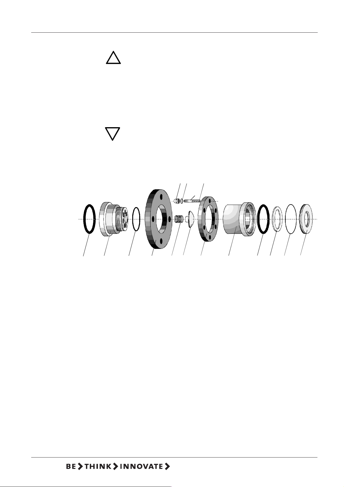
8.3 Cleaning the Suction and Pressure Valves
WARNING Wear protective gloves and glasses when executing
!
● Loosen the cap nuts (8) on the flange (1).
● Remove the valve housing (2/9) and other parts of the valve.
● Remove the other internal parts (see assembly diagram) and clean, or
replace if necessary.
● Fit the valvetogether again according to the assembly diagram.
● Screw in the valve.
CAUTION Take heed that the O-ring is fitted exactly into the
work at the dosing head, connections or lines!
provided groove.
Observe the flow direction (indicated by an arrow)!
11
8
7
6 x
913101441
1 Flange
2 Valve housing
3 Valve seat
4 Valve disk
6 Double-end stud
7 Washer
8 Cap nut
9 Valve housing
10 Supporting ring
11 O-ring
12 O-ring
13 O-ring
14 Spring
15 Valve disk
6
211
15 12
3
31V3.0
Page 32

8.4 Exchanging the Diaphragm
!
DMX model 227
WARNING Wear protective gloves and glasses when carrying out
work on the dosing head, connections or lines!
● Loosen the 6 screws (2) on the dosing head (3).
● Remove the dosing head (3).
● Unscrew the diaphragm (1) to the left.
● Refit the retaining ring (4), shim ring (5), lip seal (7) and supporting ring (6),
replacing if necessary.
● Screw in the new diaphragm (1).
● Remove the ventilation hood of the motor, and rotate the fan blades until
the diaphragm reaches the rear dead point.
● Attach the dosing head (3), and tighten the screws (2) diagonally.
Max. torque 70-80 Nm.
● Vent the pump, and restart.
CAUTION After initial start-up and after each diaphragm
exchange, tighten the fixing screws of the dosing head:
After approx. 6 to 10 working hours or two days, tighten
the dosing head screws crosswise using a torque
wrench, torque 70-80 Nm.
7
2
3
5
6
1
4
32 15.720023-V3.0
Page 33

DMX model 227
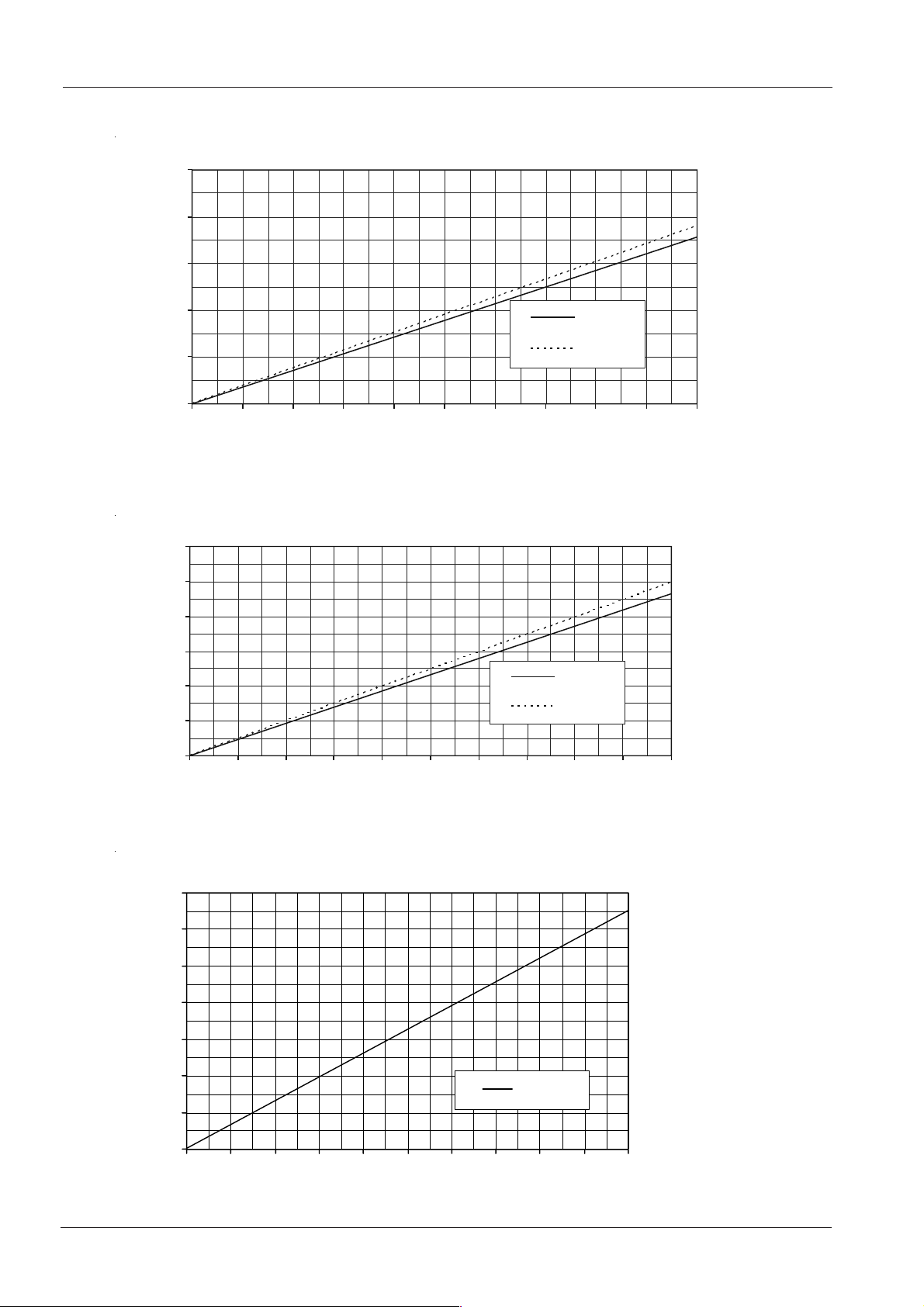
A. Appendix: Dosing Curves for DMX model 227
The dosing curves shown here are trend curves
They refer to:
❏ Performance of single pump
(the flow rate is doubled for the double pump)
❏ Water as the dosing medium
❏ Zero point of the dosing pump at a counterpressure of 3 bar
❏ Standard version of pump
Q = flow rate
f = drive frequency
100
0
Q [l/h]
80
60
40
20
2.000
Q [l/h]
DMX 430-5
0
0
0
p = 5bar
0
p = 2bar
0
0
1
0
2
0
3
0
4
0
5
0
6
0
7
0
8
0
9
0
f [Hz]
10
0
DMX 77 0-3
1.500
1.000
500
0
0 102030405060708090100
p = 3bar
f [Hz]
33V3.0
Page 34
Q [l/h]
5
DMX model 227
DMX 860-5
2500
2000
1500
Q [l/h]
1000
500
0
0 102030405060708090100
p = 5bar
p = 2bar
DMX 1120 -
3000
2500
2000
1500
1000
500
0
0 102030405060708090100
p = 5bar
p = 2bar
f [Hz]
f [Hz]
DMX 1520-3
3.500
Q [l/h]
3.000
2.500
2.000
1.500
1.000
500
0
0 102030405060708090100
p = 3bar
f [Hz]
15.720023-V3.0
34
Page 35

DMX model 227
4.500
Q [l/h]
4.000
3.500
3.000
2.500
2.000
1.500
1.000
500
DMX 20 00-3
p = 3bar
0
0 102030405060708090100
f [Hz]
35V3.0
Page 36

DMX model 227
Declaration of Conformity
We Grundfos declare under our sole responsibility that the
products DMX model 227, to which this declaration relates, are in
conformity with the Council Directives on the approximation of the
laws of the EC Member States relating to
⎯ Machinery (98/37/EC).
Standards used: EN ISO 12100 and EN 809: 1998.
⎯ Electromagnetic compatibility (89/336/EEC).
Standards used:
EN 61000-3-11: 2000,
EN 61000-6-2: 2001 and
EN 61000-6-4: 2001.
⎯ Electrical equipment designed for use within certain voltage limits
(73/23/EEC) [95].
Standard used: EN 61010-1: 2002.
Konformitätserklärung
Wir Grundfos erklären in alleiniger Verantwortung, dass die
Produkte DMX Modell 227, auf die sich diese Erklärung
bezieht, mit den folgenden Richtlinien des Rates zur
Angleichung der Rechtsvorschriften der EG-Mitgliedstaaten
übereinstimmen:
⎯ Maschinen (98/37/EG).
Normen, die verwendet wurden: EN ISO 12100 und EN
809: 1998.
⎯ Elektromagnetische Verträglichkeit (89/336/EWG).
Normen, die verwendet wurden: EN 61000-3-11: 2000, EN
61000-6-2: 2001 und EN 61000-6-4: 2001.
⎯ Elektrische Betriebsmittel zur Verwendung innerhalb
bestimmter Spannungsgrenzen (73/23/EWG) [95].
Norm, die verwendet wurde: EN 61010-1: 2002.
Déclaration de Conformité
Nous Grundfos déclarons sous notre seule responsabilité que les
produits DMX modèle 227 auxquels se réfère cette déclaration sont
conformes aux Directives du Conseil concernant le rapprochement
des législations des Etats membres CE relatives à
⎯ Machines (98/37/CE).
Standards utilisés: EN ISO 12100 et EN 809: 1998.
⎯ Compatibilité électromagnétique (89/336/CEE).
Standards utilisés:
EN 61000-3-11: 2000,
EN 61000-6-2: 2001 et
EN 61000-6-4: 2001.
⎯ Matériel électrique destiné à employer dans certaines limites
de tension (73/23/CEE) [95].
Standard utilisé: EN 61010-1: 2002.
Dichiarazi on e di Conf ormità
Noi Grundfos dichiariamo sotto la nostra esclusiva
responsabilità che i prodotti DMX modello 227 ai quali questa
dichiarazione se riferisce sono conformi alle Direttive del
Consiglio concernente il ravvicinamento delle legislazioni degli
Stati membri CE relative a
⎯ Macchine (98/37/CE).
Standard usati: EN ISO 12100 e EN 809: 1998.
⎯ Compatibilità elettromagnetica (89/336/CEE).
Standard usati:
EN 61000-3-11: 2000,
EN 61000-6-2: 2001 e
EN 61000-6-4: 2001.
⎯ Materiale elettrico destinato ad essere utilizzato entro certi
limiti di tensione (73/23/CEE) [95].
Standard usato: EN 61010-1: 2002.
Bjerringbro, 15th May 2006
Jan Strandgaard
Technical Director
36
15.720023-V3.0
Page 37

Page 38

Page 39

Page 40

Being responsible is our foundation
Thinking ahead makes it possible
Innovation is the essence
96681390 1107
Repl.
www.grundfos.com
en
 Loading...