

Page 1

DMS, Variant B
GRUNDFOS INSTRUCTIONS
Installation and operating instructions
Page 2

GB Declaration of Conformity
We, Grundfos Alldos, declare under our sole responsibility that the
products DMS, to which this declaration relates, are in conformity with
these Council directives on the approximation of the laws of the EC
member states:
– Machinery Directive (2006/42/EC).
Standards used: EN 809: 1998, EN ISO 12100-1+A1: 2009,
EN ISO 12100-2+A1: 2009
– Low Voltage Directive (2006/95/EC).
Standard used: EN 60204-1+A1: 2009.
– EMC Directive (2004/108/EC).
Standards used: EN 61000-6-2: 2005, EN 61000-6-4: 2007.
DE Konformitätserklärung
Wir, Grundfos, erklären in alleiniger Verantwortung, dass die Produkte
DMS, auf die sich diese Erklärung bezieht, mit den folgenden Richtlinien
des Rates zur Angleichung der Rechtsvorschriften der EUMitgliedsstaaten übereinstimmen:
– Maschinenrichtlinie (2006/42/EG).
Normen, die verwendet wurden: EN 809: 1998, EN ISO 12100-1+A1:
2009, EN ISO 12100-2+A1: 2009.
– Niederspannungsrichtlinie (2006/95/EG).
Norm, die verwendet wurde: EN 60204-1+A1: 2009.
– EMV-Richtlinie (2004/108/EG).
Normen, die verwendet wurden: EN 61000-6-2: 2005,
EN 61000-6-4: 2007.
FR Déclaration de Conformité
Nous, Grundfos, déclarons sous notre seule responsabilité, que les
produits DMS, auxquels se réfère cette déclaration, sont conformes aux
Directives du Conseil concernant le rapprochement des législations des
Etats membres CE relatives aux normes énoncées ci-dessous :
– Directive Machines (2006/42/CE).
Normes utilisées : EN 809 : 1998, EN ISO 12100-1+A1 : 2009,
EN ISO 12100-2+A1 : 2009.
– Directive Basse Tension (2006/95/CE).
Norme utilisée : EN 60204-1+A1: 2009.
– Directive Compatibilité Electromagnétique CEM (2004/108/CE).
Normes utilisées : EN 61000-6-2: 2005, EN 61000-6-4: 2007.
IT Dichiarazione di Conformità
Grundfos dichiara sotto la sua esclusiva responsabilità che i prodotti
DMS, ai quali si riferisce questa dichiarazione, sono conformi alle
seguenti direttive del Consiglio riguardanti il riavvicinamento delle
legislazioni degli Stati membri CE:
– Direttiva Macchine (2006/42/CE).
Norme applicate: EN 809: 1998, EN ISO 12100-1+A1: 2009,
EN ISO 12100-2+A1: 2009.
– Direttiva Bassa Tensione (2006/95/CE).
Norma applicata: EN 60204-1+A1: 2009.
– Direttiva EMC (2004/108/CE).
Norme applicate: EN 61000-6-2: 2005, EN 61000-6-4: 2007.
ES Declaración de Conformidad
Nosotros, Grundfos, declaramos bajo nuestra entera responsabilidad
que los productos DMS, a los cuales se refiere esta declaración, están
conformes con las Directivas del Consejo en la aproximación de las
leyes de las Estados Miembros del EM:
– Directiva de Maquinaria (2006/42/CE).
Normas aplicadas: EN 809: 1998, EN ISO 12100-1+A1: 2009,
EN ISO 12100-2+A1: 2009.
– Directiva de Baja Tensión (2006/95/CE).
Norma aplicada: EN 60204-1+A1: 2009.
– Directiva EMC (2004/108/CE).
Normas aplicadas: EN 61000-6-2: 2005, EN 61000-6-4: 2007.
PT Declaração de Conformidade
A Grundfos declara sob sua única responsabilidade que os produtos
DMS, aos quais diz respeito esta declaração, estão em conformidade
com as seguintes Directivas do Conselho sobre a aproximação das
legislações dos Estados Membros da CE:
– Directiva Máquinas (2006/42/CE).
Normas utilizadas: EN 809: 1998, EN ISO 12100-1+A1: 2009,
EN ISO 12100-2+A1: 2009.
– Directiva Baixa Tensão (2006/95/CE).
Norma utilizada: EN 60204-1+A1: 2009.
– Directiva EMC (compatibilidade electromagnética) (2004/108/CE).
Normas utilizadas: EN 61000-6-2: 2005, EN 61000-6-4: 2007.
GR Δήλωση Συμμόρφωσης
Εμείς, η Grundfos, δηλώνουμε με αποκλειστικά δική μας ευθύνη ότι τα
προϊόντα DMS στα οποία αναφέρεται η παρούσα δήλωση,
συμμορφώνονται με τις εξής Οδηγίες του Συμβουλίου περί προσέγγισης
των νομοθεσιών των κρατών μελών της ΕΕ:
– Οδηγία για μηχανήματα (2006/42/EC).
Πρότυπα που χρησιμοποιήθηκαν: EN 809: 1998,
EN ISO 12100-1+A1: 2009, EN ISO 12100-2+A1: 2009.
– Οδηγία χαμηλής τάσης (2006/95/EC).
Πρότυπο που χρησιμοποιήθηκε: EN 60204-1+A1: 2009.
– Οδηγία Ηλεκτρομαγνητικής Συμβατότητας (EMC) (2004/108/EC).
Πρότυπα
που χρησιμοποιήθηκαν: EN 61000-6-2: 2005,
EN 61000-6-4: 2007.
NL Overeenkomstigheidsverklaring
Wij, Grundfos, verklaren geheel onder eigen verantwoordelijkheid dat
de producten DMS waarop deze verklaring betrekking heeft, in
overeenstemming zijn met de Richtlijnen van de Raad in zake de
onderlinge aanpassing van de wetgeving van de EG Lidstaten
betreffende:
– Machine Richtlijn (2006/42/EC).
Gebruikte normen: EN 809: 1998, EN ISO 12100-1+A1: 2009,
EN ISO 12100-2+A1: 2009.
– Laagspannings Richtlijn (2006/95/EC).
Gebruikte norm: EN 60204-1+A1: 2009.
– EMC Richtlijn (2004/108/EC).
Gebruikte normen: EN 61000-6-2: 2005, EN 61000-6-4: 2007.
SE Försäkran om överensstämmelse
Vi, Grundfos, försäkrar under ansvar att produkterna DMS, som
omfattas av denna försäkran, är i överensstämmelse med rådets direktiv
om inbördes närmande till EU-medlemsstaternas lagstiftning,
avseende:
– Maskindirektivet (2006/42/EG).
Tillämpade standarder: EN 809: 1998, EN ISO 12100-1+A1: 2009,
EN ISO 12100-2+A1: 2009.
– Lågspänningsdirektivet (2006/95/EG).
Tillämpad standard: EN 60204-1+A1: 2009.
– EMC-direktivet (2004/108/EG).
Tillämpade standarder: EN 61000-6-2: 2005, EN 61000-6-4: 2007.
FI Vaatimustenmukaisuusvakuutus
Me, Grundfos, vakuutamme omalla vastuullamme, että tuotteet DMS,
joita tämä vakuutus koskee, ovat EY:n jäsenvaltioiden lainsäädännön
yhdenmukaistamiseen tähtäävien Euroopan neuvoston direktiivien
vaatimusten mukaisia seuraavasti:
– Konedirektiivi (2006/42/EY).
Sovellettavat standardit: EN 809: 1998, EN ISO 12100-1+A1: 2009,
EN ISO 12100-2+A1: 2009.
– Pienjännitedirektiivi (2006/95/EY).
Sovellettu standardi: EN 60204-1+A1: 2009.
– EMC-direktiivi (2004/108/EY).
Sovellettavat standardit: EN 61000-6-2: 2005, EN 61000-6-4: 2007.
DK Overensstemmelseserklæring
Vi, Grundfos, erklærer under ansvar at produkterne DMS som denne
erklæring omhandler, er i overensstemmelse med disse af Rådets
direktiver om indbyrdes tilnærmelse til EF-medlemsstaternes
lovgivning:
– Maskindirektivet (2006/42/EF).
Anvendt standarder: EN 809: 1998, EN ISO 12100-1+A1: 2009,
EN ISO 12100-2+A1: 2009.
– Lavspændingsdirektivet (2006/95/EF).
Anvendt standard: EN 60204-1+A1: 2009.
– EMC-direktivet (2004/108/EF).
Anvendte standarder: EN 61000-6-2: 2005, EN 61000-6-4: 2007.
Pfinztal, 15th July 2010
Ulrich Stemick
Technical Director
ALLDOS Eichler GmbH
Reetzstr. 85, D-76327 Pfinztal, Germany
Person authorised to compile technical file and
empowered to sign the EC declaration of conformity.
2
Page 3

3
DMS, Variant B
Installation and operating instructions 4
Montage- und Betriebsanleitung 22
Notice d'installation et d'entretien 41
Istruzioni di installazione e funzionamento 59
Instrucciones de instalación y funcionamiento 77
Instruções de instalação e funcionamento 95
Οδηγίες εγκατάστασης και λειτουργίας 113
Installatie- en bedieningsinstructies 131
Monterings- och driftsinstruktion 149
Asennus- ja käyttöohjeet 167
Monterings- og driftsinstruktion 185
Page 4

4
Original inst alla ti on and ope rat ing ins truct ion s.
CONTENTS
Page
1. General de scr ipti on 4
1.1 Applicat ion s 4
1.2 Type key 5
2. Technical data 6
2.1 Mechanic al da ta 6
2.2 Electrical data 6
2.3 Dimensi on s 6
3. Installati on 7
3.1 Safety instructions 7
3.2 Installati on e nv i ro nm en t 7
3.3 Installation o f p um p 7
3.4 Installation example 8
3.5 Electrical conne ct ion 8
4. Functions 9
4.1 Control panel 9
4.2 Start/stop of pum p 10
4.3 Priming/ve nting of pu mp 10
4.4 Indicator lights 10
4.5 Menu 11
4.6 Counters 12
4.7 Resetti ng 13
4.8 Return 13
4.9 Language 14
4.10 Measuring units 15
4.11 Co n tro l pa nel lock 16
5. Start-up 17
6. Calibra ti on 17
6.1 Direct cali brat ion 18
6.2 Indirect ca libr a tion 19
6.3 Check calib r ati on 20
7. Mainte na nce 20
8. Service 20
9. Fault finding chart 21
10. Disposa l 21
1. General descripti on
The GRUNDFOS DMS dosing pump is a self-priming
diaphragm pump.
The pump c on s ists o f:
•a cabinet incorporating the drive unit an d
electroni cs,
•a dosing head with back plate, dia ph r ag m ,
valves, connections and vent valve and
•a control panel incorporating dis play and
buttons.
The pump is fi t te d wi th a sy nch r on ou s m o to r, w h ich
is started an d stopped by mean s of the i nteg rated
electronics. The capacity is varied by changing the
stroke frequency. The pump always generates a
complete stroke with full stroke length and the speed
of the suction and dosing strokes is constant, irrespective of the ca pa ci t y se tt ing . T h e mo t or d ri v e als o
eliminates undesired peak values during the suction
and dosing strokes. As the pump is always dosin g at
full stroke len gth , i t e nsur es the sa m e hig h a ccu racy
and suction c apab ilit y, irrespective o f th e capa city,
which is infinitely variable in the ratio of 1:100.
The pump features an LCD display and a userfriendly co ntr o l pan el w h ich gi ves access to th e
pump func tio ns .
1.1 Applications
The DMS do sin g pu m p is designed f or h an dl in g
chemicals within the following ranges of applications:
• Drinking water treatment.
• Wastewater treatment.
• Swi mm in g po ol water tre atm ent .
• B o iler water treatm e nt .
• Co o ling wa te r tr ea tm en t.
• P r oc ess wa te r tr ea tm en t.
• Washing systems.
Before be gi nn i ng in stall a tio n pr o c ed ur e s,
these installation and operating instructions should be s tu die d ca re fu lly. The
install ation and o pera tion s houl d als o be in
accordance wi t h loca l r e gu lat ion s a n d
accepted co de s o f go od p ra ct i ce .
Page 5

5
1.2 Type key
(Cannot be u s ed f or p um p co nf i gu rat io n. )
Code Example DMS 2 - 11 B - PP/ E/ C - F - 2 1 1E F
Grundfos do si n g pu m p
Pump range DMS
Maximum pres sur e [bar]
B
Control variant:
Standard
PP
PV
SS
Dosing head mater ia l:
Polypropyle ne
PVDF
Stainless steel 1.4401
E
V
T
Gasket ma te r ia l:
EPDM
FKM
PTFE
C
SS
Valve ball material:
Ceramics
Stainless steel 1.4401
F
Control panel:
Front-fitted
1
Voltage:
1 x 230 V, 50 Hz
1
2
Valves:
Standard valve
Spring-loaded valve
1
2
3
4
5
6
A
B
E
F
Connection, suction/discharge:
Tubing 6/9
Tubing 4/6
supplied with th e pump
Tubing 6/9
Tubing 6/12+9 /1 2
supplied with th e pump
Tubing 4/6
Tubing 6/9
Tubing 6/12
Tubing 9/12
Threaded Rp 1/4
Threaded Rp 3/8
Cementing d.10
Cementing d.12
F
B
G
I
E
J
Mains plug:
EU (Schuko)
USA, CAN
UK
AU
CH
JP
Page 6

6
2. Tec hnical data
2.1 Mechanic al data
*1 Irrespective of counter pressure
*
2
Maximum suction lift 1 metre
2.2 Electrical data
2.3 Dimensions
See dimensions at the end of these instructions.
All dimensions are in mm.
DMS 2 DMS 4 DMS 8 DMS 12
Maximum capacity *
1
[l/h] 2.5 4 7.5 12
Maximum pressure [bar] 11 7 5.4 3.4
Maximum strok e rate per minute [stroke/min.] 180
Maximum suction lift during operation [m] 6
Maximum suction lift whe n pr imin g wit h w et va lves [ m] 1.8 2 3 3
Maximum viscosity with spring -loade d valves *
2
[mPas] 500
Maximum viscosity without spring-loaded valves *
2
[mPas] 200
Diaphragm diameter [mm] 28 30 38 42.5
Liquid temp erat ure [° C] 0 to 50
Ambient temperature [°C] 0 to 45
Accuracy of repea tability ±1%
Sound pressure level [dB(A)] <70
DMS 2, 4, 8, 12
Voltage [VAC], frequency [Hz] 1 x 230, 50
Maximum current consumption [A] 0.1
Power cons um p tio n, P
1
[W] 16
Enclosure cl ass IP 65
Insulation cl ass F
Supply cable 1.5 m H05RN-F with plug
Page 7

7
3. Installation
3.1 Safety instructions
• Wh en working with chem icals, local safet y rules
and regulations must be observed (e.g. wear protective clothes).
• B efor e startin g work on the dosin g pum p and system, disc on ne ct t he elec t ri c ity s up ply to th e p um p,
ensuring th at it cannot b e acc ide ntally switche d
on. Before reconnecting the electri city supply,
make sure that the dosing hose is positioned in
such a way t hat a ny ch em ic al left in the dosing
head is not ejected, thereby exposing persons to
danger.
• If th e ve nt valve in th e do sin g he ad is used, it
must be connected to a hose which is led back to
the tank.
• When changing a chemical, make sure that the
materials of t he d osin g pu m p an d syst em a r e
resistant to the new chemical. If there is any risk
of chemical reaction between the two types of
chemicals, clean the pump and system thoroughly
before adding the new chemical.
Proceed as follows:
Place the sucti on ho se in water and pr ess the
button unt i l r es i du al ch em ic a l h as be e n r e mo ve d.
Note: When th e bu tt on s and ar e p r ess ed
simultaneously, the pump can be set to run for a
specific num be r of sec on ds a t ma xim um capa city.
The remaining number o f sec on ds will ap p ear in
the display. The maximum valu e is 30 0 secon ds.
• The liquid is under pressure and may be hazardous.
3.2 Installation environment
• E xpos ure to dir ect sun lig ht shou ld be avo ided.
This applies espe cially to pu m ps with pla sti c d osing heads, as this material can be damaged by
sunlight.
• If th e pump is in stalle d outside, an e ncl osu r e o r
similar pr ot ect i on is required t o protect the pump
against r ain a nd similar we at he rs.
3.3 Installation of pump
• Se e also th e instal lation examp le in se ction 3.4.
• Note: The do sing head may co ntain water from
the factory test. If a liquid which must not come
into contact with w ate r is to be d os ed, it is recommended to let the pump r un w i th an other liquid to
remove the wat er fro m the dosi ng head befor e
installation .
• Alw ays install the pu mp on the sup po rt i ng f oo t
with vertical suction and discharge ports.
• Always use suitable tools fo r the mounting of plastic parts. Never a pp ly un ne ce ssa ry fo r ce.
• Make sure that the dosing pump and system are
designed i n su ch a wa y t ha t n ei t he r s yst em e qu i pment nor buil ding s are da mage d in ca se of leak age from the pump or rupture of hoses/pi pes. The
installation o f le akage hoses a nd c oll e ct ing tan ks
is recommended.
• Ma ke sure that the drain ho le in th e dosin g head
points downwards, see fig. 1.
Note: It is important that the drain pipe/hole is not
inserted di rect in to the tank cont en ts, a s g a sse s
may penetrate into the pump.
Fig. 1
100%
100%
TM01 8420 5099
Drain hole
Page 8

8
3.4 Installation ex amp le
The drawing in fig. 2 shows an installation example.
Fig. 2
3.5 Electrical connection
• Th e el ectrical conn ect ion o f the pump sh ou ld b e
carried out by qualified persons in accordance
with local regulati on s.
• For electrical data of the pump, see section 2.2.
The DMS pump can be ins talled in ma ny di fferent wa ys. Th e tank is a G RUND FOS c hemic al tank.
TM01 8452 3600
Page 9

9
4. Functions
4.1 Control panel
Fig. 3
TM01 8453 0100
ml/h
100%
LCD display,
see section 4.5
Navigation/
settings,
see section 4.5
Max. capacity
(priming),
see section 4.3
Green
indicator light,
see section 4.4
Red
indicator light,
see section 4.4
Mains connec tion
On/off button,
see section 4.5
Menu,
see section 4.5
Navigation/
settings,
see section 4.5
Page 10

10
4.2 Start/stop of pum p
The pump can be started/stopped in two different
ways:
• Locally on the pump control panel.
• By switc hing on/o ff the electricity sup ply.
4.3 Priming/venting of pump
The pump control panel incorporates a button.
Press this bu tto n if th e m a xim um p ump ca pa cit y is
required over a short period, e.g. during start-up.
When the button is released, the pump automatically
returns to th e pr evious operat i ng m ode.
During priming/ventin g, it is recommende d to let the
pump run w ith out a c ou nter p res s ur e or to l o os en t he
vent valve by giving it a 1/8 to 1/4 turn.
Note: When th e bu tt on s and ar e p r essed
simultaneously, th e pump can be set to run for a specific number of seconds at maximum capacity. The
remaining number o f s ec onds will appe ar in t he d isplay. The maximum value is 300 seconds.
4.4 Indicator lights
The green and red indicator lights on the pump are
used for o pe ra ti n g an d fa ult indication .
The functions of the indicator lights appear from the
table below :
Condition
Green
LED
Red
LED
Display
Pump running On Off
Normal
indicati on
Set to stop Flashing Off
Normal
indicati on
Pump fault Off On EEPROM
Supply failure Off Off Off
Overheati ng O ff On
MAX.
TEMP.
100%
100%
Page 11

11
4.5 Menu
The pump features a user-friendly menu which is
activat ed by p re ssi ng the button . Duri n g start-up,
all texts will appear in Englis h l angu age. To select
language, see secti on 4.9.
All menu items are described in the following sections. When appears at a menu item, it means
that this item is a ctiv ated . By selec tin g “RET UR N”
anywhere in the menu structure, you will return to the
operating d isp l ay wi t ho ut ch an ge s.
Fig. 4
See section 6. See section 4.8
See section 4.6 See section 4.9
See section 4.11 Se e sectio n 4.10
See section 4.7
Page 12

12
4.6 Counters
The pump can display “non-resettable” counters for:
•“QUANTITY”
Accumulated value of dosed quantity in litres or
US gallons.
•“STROKES”
Accumulated nu mber of do sing str okes.
•“HOURS”
Accumulate d numb er of op erat ing hou rs
(Power on).
•“POWER ON”
Accumulate d numb er of tim es the ele ctrici ty sup ply has be en s wi tc he d on .
Fig. 5
Total dosed
quantity
To tal number
of strokes
To tal number
of operating
hours
To tal number
of starts
Operating display
Page 13

13
4.7 Resetting
When “DEFAULT” is activated, the pump will return
to the factory settings.
Note: The calibr at ion is a lso se t b ac k to the defau lt
setting. This means that a new calibration is required
when the “ D EFAULT” function ha s b ee n us ed .
Fig. 6
4.8 Return
Fig. 7
The “RETURN” fun ction m ake s it p ossib le to r etur n
from any level in the menu to the operating display
without chan g es afte r th e me nu fun ctions have been
used.
Operating display Operating display
without ch an ge s
Page 14
14
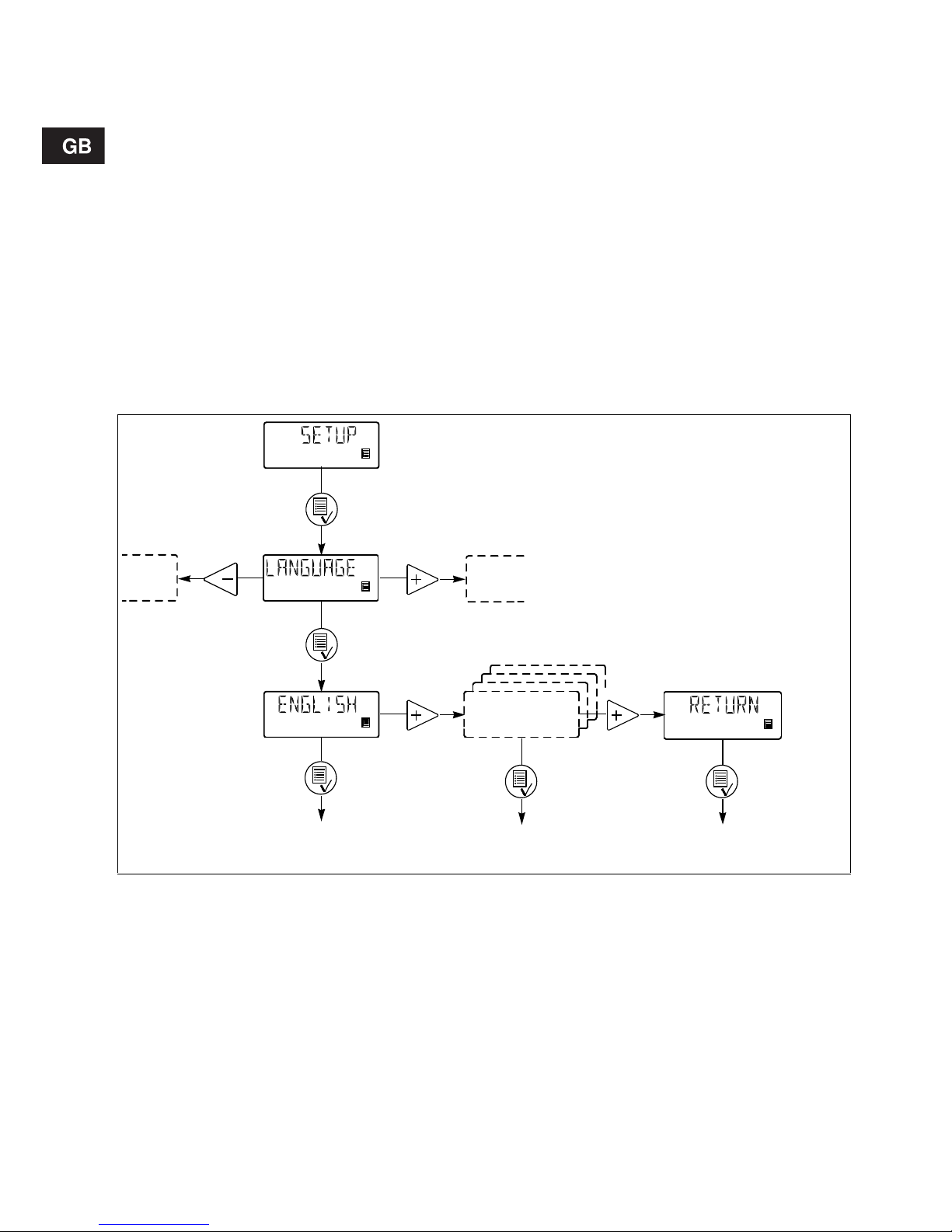
4.9 Language
The display text can be displaye d in one of the
following languag es:
• Eng lish
•German
•French
• Italia n
• Spanish
• P or tu gu ese
•Dutch
•Swedish
•Finnish
•Danish
• Cze ch
•Slovak
• Polis h
•Russian
Fig. 8
Operating di splay Operatin g displa y Operating dis pla y
without changes
Page 15

15
4.10 Measuring units
It is possible to s ele ct m etric un its (litr e/ mil lilitr e) o r
US units (gallons/millilitre).
Metric measuring units:
• In manual and analog mode s, set the quantity to
be dosed in litres p e r h our (l /h) o r millilit re s per
hour (ml/h ).
• In pulse mode, set the quantity to be dose d i n
ml/pulse. The actu al capacit y is indica ted in l itres
per hour (l/h) or m illil itr es pe r ho ur (m l/h ).
• For calibration, set the qu a nti ty to be d os ed in
ml per 100 stroke s.
• In timer and batch modes, set the quantity to be
dosed in litres (l) or millilitres (ml).
• Un de r th e “ QU A NT IT Y” me nu it em i n t he
“COUNTERS” menu, the dosed quantity is indicated in li tr es.
US measuring units:
• In manual and analog modes, set the quantity to
be dosed in ga llons pe r ho ur (gph) .
• In pulse mode, set the quantity to be dosed in
ml/pulse. The actual capac ity is indicated in
gallons per hour (gph).
• For calibration, set the q u an tity to b e do se d in
ml per 100 strokes.
• In timer and batch modes, set the quantity to be
dosed in gallons (gal).
• Under the “QUANTITY” menu item in the
“COUNTER S” m en u, th e dosed quantity is indicated in US gallons (gal).
Fig. 9
Operating d i sp lay
3 x
Operating d isplay
Page 16

16
4.11 Control panel lock
It is possible to lo ck th e b u tto ns o n t he co n tro l pa nel
to prevent malfunction of the pump. The locking
function can be set to “ON” or “OFF”. The default
setting is “O FF” .
A PIN code must be en tere d to cha nge fr om “OFF” to
“ON”. When “ON” is sele cted for the firs t time,
“_ _ _ _” will ap pe ar in th e di splay. If a code h as
already been entered, it will appear when an attempt
to change to “ON” is made . This co de can eit he r be
re-entered or changed.
If no code has been entered, a code must be set.
If a code has already been entered, active digits are
flashing.
If attempts are made to operate the pump in locked
condition, “LOCKED” will appear in the disp la y f or
2 seconds, followed by “_ _ _ _”. A code must be
entered. If the entering of a code has not been
started within 10 seconds, the operating display without changes w ill app ear.
If a wrong code is e nt ered, “ L OCKED ” w ill app ear in
the display for 2 seconds, followed by “_ _ _ _”. A
new code must be entered. If the entering of a code
has not been started within 10 seconds, the operating display without ch an ges will a pp ear. This display
will also appea r if t he e nt erin g o f th e c orre ct code
exceeds 2 minutes.
If the locki ng fu nction has bee n ac tiva te d bu t th e
control panel is unlock ed , t he co n trol pane l wi ll b e
locked a uto m at ica ll y if i t is no t op er at ed fo r 2 minutes.
The locking function can also be reactivated by
selecting “ON” in the “LOCK” menu. The previously
entered code will then appear and must be reentered by pressing the button four times. The
code can also be changed.
The control pan el can be unlocke d eit her by mea ns
of the selected code or th e facto ry code 2583.
The following buttons and inputs are still active when
the panel is locked:
• P r im i ng ( -button).
• On/off butto n.
• All ex ternal inputs.
Fig. 10
Activati ng t h e lo ck in g f un c ti on a n d locking t h e
control panel:
1. Select “LOCK” in t he menu.
2. Sel e ct “O N” by means of th e bu tt on s and
and confirm with .
3. Enter or re-enter a code by means of the buttons
, and .
The locking fu nc t ion ha s no w been acti v ated and th e
control panel is locked .
Unlocking the cont rol panel (wit hout de activa ting
the locking function):
1. Press once. “LOCK ED” appea rs in the displ ay
for 2 seco nd s, fo ll ow ed b y “ _ _ _ _” .
2. Enter the code by means of the buttons ,
and *.
The control panel has now been u nlocke d and will
automatically be locked a ga in i f th e con tr ol pan el is
not operat ed for 2 minute s.
Deactivating the l ocking function:
1. Un l oc k t he control pa ne l a s d es cr i be d ab ov e.
2. Select “LOCK” in the menu.
3. Select “OFF” by mean s of the bu tton s and
and confirm wi th .
The locking function has now been deactivated and
the control panel is unlo cke d.
* The panel can al w ay s be un l o cke d wit h co de 2583.
100%
Operating display Operating display
Page 17

17
5. Start-up
If the pump is not operating satisfactorily, see section 9. Fault finding chart.
6. Calibration
It is importan t tha t th e pu mp is ca lib ra te d a fter in stallation to ensure that the correct value (ml/h or l/h)
appears in the display.
The calibration can be carried out in three different
ways:
• Direct cal ib r at io n (recommended).
The dosed quantity of 100 strokes is measured
directly. See sectio n 6.1.
• Indirect calibration.
A calibration factor selected from a table is used
for the specific ins ta llat ion. Th is meth od c an b e
used if it is n ot po ssi ble to c ar ry o ut a dir ec t c alibration. Indirect ca libr atio n w ill n ev er b e as ac cu rate as direct cal ibr ation . See section 6.2.
• Check calibration. See section 6.3.
Step Action
1
Connect the hoses/pipes:
• Connect the suction and dosing hoses/pipes to the pump.
• Co n ne ct a hose to the ve nt va lve , if required, an d le ad th e ho se to t he
tank.
2
Switch on t h e e le ct r ic it y su p ply:
• T he d isp la y is on .
• The green indicator light is flashing (the pump has stopped).
• Select language, if required, see section 4.9.
3
Start the pump:
• Start th e pu mp b y p r essing the on/o ff b ut ton .
• The green indicator light is permanently on.
4
Priming/venting:
• Press the button on the pump control panel and let the pump run
without a counter pressure. Loosen the vent valve by giving it a 1/8 to
1/4 turn, if required.
When the b ut to ns and ar e pr es se d simultaneous l y d u rin g pr i m ing, the pump can be set to run for a specific number of seconds at
maximum capacity.
5
Calibration:
• When the pump has been primed and is running at the right counter
pressure, calibr ate the pu mp, see section 6.
100%
100%
100%
100%
100%
Page 18

18
6.1 Direct calib ratio n
Before calibration , make sure:
• th at the pump is installe d with foo t va lve, inje cti on
valve, etc. in th e ex isti ng sy ste m.
• that the pump is running at the counter pressure it
is supposed to operate at (adjust the counter
pressure valve, if required).
• that the pump is operating with the correct suction
lift.
To car ry out a direct cal ibr ation , proce ed as fo llow s:
Action Pump disp lay
1. Vent the do sin g he ad a nd t he su ct i on h ose.
2. Stop the p um p. T h e g r ee n LE D is flashin g.
3. Fill a gr aduate d glass wit h do sing liquid, Q
1
.
DMS 2: approx. 40 ml DMS 8: approx. 150 ml
DMS 4: approx. 150 ml DMS 12: approx. 250 ml
4. Rea d and no te the qu antit y Q
1
.
5. Place the sucti on hose in the graduated glass
6. Go to th e ca libr at ion m e nu , see section 4.5.
7. Pres s the bu tton tw ice.
8. The pump is performing 100 dosing strokes.
9. The factory-calibration value appears in the display.
10.Remove the suction hose from the graduated glass
and read Q
2
.
11. Set the display value to Q
d
= Q1 – Q2.
12.Confirm with the button.
13.The pump is now calibrated and returns to the
operating display.
Set value
to Q
d
Operating display
Q
1
Q
2
Q
d
Page 19

19
6.2 Indir ect cal i bration
A value from the following table is to be added to the
default fac tor y calibration v alu e in the disp la y. To
reset the p u mp to the factory c alibration valu e, activate the “DEFAULT” function, see section 4.7.
To us e th e va lue s, th e following must be fu lfille d:
• The viscosity and density of the liquid to be dosed
must not differ considerably from w ater at 20°C.
• A G RUND FO S installa tion kit or c or resp onding
foot valv e, inj e ct ion va l ve an d ho se dia met er mus t
be used.
• The length of the dosing hose must not exceed
6 metres.
• The suction lift must lie between 0.1 and 1.5 metres.
Adding the val ue:
Fig. 11
Pump type
Values to be added to the calibration value at various counter pressures [bar]
0-1 1-2 2-3 3-4 4-5 5-6 6-8 8-10 10-12
DMS 2 1.4 1.1 0 .8 0. 5 0.2 -0.2 -0.6 -1.2 -1.8
DMS 4 2.2 1.6 1 .0 0.3 -0.3 -1 .0 -1.9 -3 .2 DMS 8 2.0 1.2 0.4 -0.4 -1.2 -2.0 - - DMS 12 1.3 0.4 -0. 4 -1.3 - - - - -
Operating display
without c ha ng es
Operating d i sp lay
Set value
to table value
+ display value
Page 20

20
6.3 Check calibr atio n
In check calibr ati on, t he ca libra tio n va lue is ca lcu lated by reading the consumption of chemical in a
specific pe ri o d an d co mpa rin g th i s w i th th e nu m be r
of dosing strokes performed in the same period.
This calibratio n m e th od is ve ry ac cur a te an d es pe cially suitable for check calibration after long periods
of operation or if direct calibration is impossibl e. The
calibratio n c an f or in stan ce be ca r rie d ou t w he n th e
chemical tank is replaced or filled.
To carr y out a che ck calibr ati on, proc ee d as follow s:
1. Stop the pump by pressing the button.
2. Rea d t he co u nte r an d note the nu mb er o f dosing
strokes, se e sec tio n 4. 6.
3. Rea d an d no te the quantit y in the chemic al tank .
4. Star t the pu mp by pre ssin g the button and let
it run for at leas t 1 hour. The longer the pump is
operating, the more accurate the calibration will
be.
5. Stop the pump by pressing the button.
6. Rea d t he co u nte r an d note the nu mb er o f dosing
strokes, se e sec tio n 4. 6.
7. Rea d an d no te the quantit y in the chemic al tank .
8. Calc u la te th e do se d quantity in m l a nd t he
number o f d osing stroke s pe rf or me d du ring the
operating period.
9. Calcula te th e ca librat ion v alue as fo llows:
(dosed quantity in ml/dosing strokes) x 100.
10.Set the calculated value in the calibration menu
like for indirect calib ration, see sectio n 6.2.
7. Maintenance
The pump is maintenance-free. However, it is recommended to k ee p th e p u mp clean.
The dosing pump is produced according to the highest quality standards and has long life. The pump
incorporates wear parts such as diaphragm, valve
seat and valve balls.
To en sur e long life an d t o re du ce th e risk of distu rbance of operation, visual checks should be carried
out regularly.
It is possibl e to order dosing heads, valves and diaphragms i n m a te ria l s w hich are suita ble fo r th e sp ecific liquid to be pumped. See the product numbers
at the end of these instructions.
8. Service
Before ret ur nin g th e pu m p t o GRU NDF OS fo r service, the s afety declaration at the end of these instructions must be f illed in b y a u thor ize d pe rso nne l a nd
attached to th e pu mp in a v i sib le po siti on .
Note: If a pump has been used for a liquid which is
injurious to h ealth o r to xic, the pu mp will b e cla ssified as contaminated.
If GRUNDFOS is requested to service the pump, it
must be ensured that the pump is free from substance s that can be injurious to he alth or toxic. If the
pump has been used for such subs tances, the pump
must be cleaned before it is returned.
If proper cleanin g is n ot p ossib le, all r eleva nt infor mation about the chemical must be provided.
If the above is not fulfilled, G RUNDFO S ca n re fu se
to accept the pump for service. Possible costs of
returning the pum p are paid by the custo mer.
The safety declaration can be found at the end of these
instructions (only in English).
Note: The replacement of the supply cable must be
carried out by an authorised GRUNDFOS ser vice
workshop.
Page 21

21
9. Fault finding chart
10. Disposal
Disposal of this product or parts of it must be carried
out according to the f ollowin g guide lin es:
1. Use the local public or private wa ste collectio n
service.
2. In ca se such wa ste collectio n serv ice does not
exist or cannot handle the materials used in the
product, please deliver the product or any hazardous m ate r ial s fr om it to your ne ar e s t
GRUNDFOS company or service work shop .
Fault Cause Remedy
The dosing has
stopped or t he o utp u t
is too low.
Valves leaking or blocked. Check and cle an valve s.
Valves incorrectly installed . Remove and fit valves. C heck th at the arro w
on the valve casing is pointing in the liquid
flow direction. Check that all O-rings have
been fitted correctly.
Suction valve or suct i on pipe /h os e
leaking or blocked.
Clean and se al the s uctio n pip e/ho se.
Suction lift too high. Install the pump in a low er p osition .
Install a priming tank.
Viscosity too high. Install a pipe/hose with larger cross-section.
Fit spring-loaded valves.
Pump out of calibration. Calibrate the pump, see section 6.
Pump dosing too little
or too much.
Pump out of calibration. Calibrate the pump, see section 6.
Pump dos i ng ir re gu larly.
Valves leaking or blocked. Check and cle an the valv es.
Leakage from drain
hole.
Diaphragm defective. Install a new diaphragm.
Frequent diaphragm
failures.
Diaphragm not fastened properly. Install a new diaphragm and ensure that the
diaphragm is fastened properly.
Counter-pr essure too high (meas ured at the pump discha rge po rt ).
Check the system. Check the injection valve, if
required. R edu c e th e do sin g st ro k e by fitt i ng a
pulsation d am p en er.
Sediment in do sing he ad. C lea n/flu sh the do sing he ad.
Subject to al te ra tio ns .
Page 22

203
Service kits
Pump
size
Valves
Materials
dosing head/
gaskets/
valve balls
Product nu mb ers
Complete dosing head
Pos. 3+9+13+14+15+18
Valves +
diaphragm
Pos. 2+3 x
pos. 3
Diaphragm
Pos. 2
Valves
3 x pos. 3
DMS 2
Standard
PP/EPDM/ceramics 96440665 96441131 96440740 96440705
PP/FKM/ceramics 96446814 96446774 96440740 96446834
PVDF/FKM/ceramics 96440667 96441133 96440740 96440707
Stainless steel/FKM/stainless steel 96440669 96441135 96440740 96440709
Springloaded
PP/EPDM/ceramics 96440666 96441132 96440740 96440706
PP/FKM/ceramics 96446815 96446775 96440740 96446835
PVDF/FKM/ceramics 96440668 96441134 96440740 96440708
Stainless steel/FKM/stainless steel 96440670 96441136 96440740 96440710
DMS 4
Standard
PP/EPDM/ceramics 96440699 96441177 96440750 96440705
PP/FKM/ceramics 96446818 96446782 96440750 96446834
PVDF/FKM/ceramics 96440701 96441179 96440750 96440707
Stainless steel/FKM/stainless steel 96440703 96441181 96440750 96440709
Springloaded
PP/EPDM/ceramics 96440700 96441178 96440750 96440706
PP/FKM/ceramics 96446819 96446783 96440750 96446835
PVDF/FKM/ceramics 96440702 96441180 96440750 96440708
Stainless steel/FKM/stainless steel 96440704 96441182 96440750 96440710
DMS 8
Standard
PP/EPDM/ceramics 96440671 96441149 96440743 96440705
PP/FKM/ceramics 96446816 96446780 96440743 96446834
PVDF/FKM/ceramics 96440673 96441151 96440743 96440707
Stainless steel/FKM/stainless steel 96440675 96441153 96440743 96440709
Springloaded
PP/EPDM/ceramics 96440672 96441150 96440743 96440706
PP/FKM/ceramics 96446817 96446781 96440743 96446835
PVDF/FKM/ceramics 96440674 96441152 96440743 96440708
Stainless steel/FKM/stainless steel 96440676 96441154 96440743 96440710
DMS 12
Standard
PP/EPDM/ceramics 96440659 96441125 96440739 96440705
PP/FKM/ceramics 96446812 96446772 96440739 96446834
PVDF/FKM/ceramics 96440661 96441127 96440739 96440707
Stainless steel/FKM/stainless steel 96440663 96441129 96440739 96440709
Springloaded
PP/EPDM/ceramics 96440660 96441126 96440739 96440706
PP/FKM/ceramics 96446813 96446773 96440739 96446835
PVDF/FKM/ceramics 96440662 96441128 96440739 96440708
Stainless steel/FKM/stainless steel 96440664 96441130 96440739 96440710
Page 23

204
TM01 9976 3500
14
13
2
4
5
6
7
8
10
11
12
3
9
15
18
Page 24

205
Dimensions
TM01 8636 3600
259
137
160
110
98
168
36
50
ml/h
100%
Page 25

206
Safety declaration
Please copy, fill in and sign this sheet and attach it to the pu mp re turn ed for s ervice.
We hereby declare th at th is pro duct:
Product type:_ _____ _____ ___ _____ ___ _____ _
Model numbe r: _ ________________________
(see pump nameplate)
is free from hazardous chemicals, biological and radioactive substances.
Fault description
Please make a circ le arou nd th e dama ged part.
In the case of an ele ctrica l or fu nction al faul t, pleas e ma rk th e cabi net.
Please give a shor t descr iptio n of the fault:
___________ ___ __ _ ____________ __ ___
Date and signature Company stamp
TM02 8953 1104
ml/h
100%
Page 26

Argentina
Bombas GRUNDFO S de Argentina S.A.
Ruta Panamericana km. 37.500 Lote 34A
1619 - Garin
Pcia. de Buenos Aires
Phone: +54-3327 414 444
Telefax: +54-3327 411 111
Australia
GRUNDFOS Pumps Pty. Ltd.
P.O. Box 2040
Regency Park
South Australia 5942
Phone: +61-8-8461-4611
Telefax: +61-8-8340 01 55
Austria
GRUNDFOS Pumpen Vertrieb Ges.m.b.H.
Grundfosstraße 2
A-5082 Gröd ig/Salzburg
Tel.: +43-6246-883-0
Telefax: +43-6246-883-30
Belgium
N.V. GRUNDFOS Bellux S.A.
Boomsesteenw eg 81-83
B-2630 Aartselaar
Tél.: +32-3- 870 7300
Télécopie: +32-3-870 7301
Belorussia
Пред став итель ство ГРУНДФОС в
Минске
220123, Минск,
ул. В. Хоружей, 22 , оф. 1105
Тел.: +(37517) 233 97 65,
Факс: +(37517) 233 97 69
E-mail: grundfos_minsk@mail.ru
Bosnia/Herzegovina
GRUNDFOS Sarajevo
Trg Heroja 16,
BiH-71000 S arajevo
Phone: +387 33 713 290
Telefax: +387 33 659 079
e-mail: grundfos@bih.net.ba
Brazil
BOMBAS GRUNDFOS DO BRASIL
Av. Humberto de Alencar Castelo Branco,
630
CEP 09850 - 300
São Bernardo do Cam po - SP
Phone: +55-11 4393 5533
Telefax: +55-11 4343 5015
Bulgaria
Grundfos Bulgaria EOOD
Slatina District
Iztochna Tangenta street no. 100
BG - 1592 Sofia
Tel. +359 2 49 22 200
Fax. +359 2 49 22 201
email: bulgaria@grundfos.bg
Canada
GRUNDFOS Canada Inc.
2941 Brighton Road
Oakville, Ontario
L6H 6C9
Phone: +1-905 829 9533
Telefax: +1-905 829 95 12
China
GRUNDFOS Pumps (Shanghai) Co. Ltd.
50/F Maxdo Center No. 8 XingYi Rd.
Hongqiao development Zone
Shanghai 200336
PRC
Phone: +86-021-612 252 22
Telefax: +86-021-612 2 53 33
Croatia
GRUNDFOS CROATIA d.o.o.
Cebini 37, Buzin
HR-10010 Zagre b
Phone: +385 1 6595 400
Telefax: +385 1 6595 499
www.grundfos.hr
Czech Republic
GRUNDFOS s.r.o.
Čajkovského 21
779 00 Olomouc
Phone: +420 -585-716 111
Telefax: +420-585-716 299
Denmark
GRUNDFOS DK A/S
Martin Bachs Vej 3
DK-8850 Bjerringbro
Tlf.: +45-87 50 50 50
Telefax: +45-87 50 51 51
E-mail: info_GD K@grundfos.com
www.grundfos.com/DK
Estonia
GRUNDFOS Pumps Eesti OÜ
Peterburi tee 92G
11415 Tallinn
Tel: + 372 606 1690
Fax: + 372 606 1691
Finland
OY GRUNDFOS Pumput AB
Mestarintie 11
FIN-01730 Vantaa
Phone: +358 -3066 5650
Telefax: +358-3066 56550
France
Pompes GRUNDFOS Distribution S.A.
Parc d’Activités de Chesnes
57, rue de Malacombe
F-38290 St. Quentin Fallavier (Lyon)
Tél.: +33-4 74 82 15 15
Télécopie: +33-4 74 94 10 51
Germany
GRUNDFOS GMBH
Schlüterstr. 33
40699 Erkrath
Tel.: +49-(0) 211 929 69-0
Telefax: +49-(0) 211 929 69-3799
e-mail: infoservice@grundfos.de
Service in Deutschland:
e-mail: kundendienst@grundfos .de
Greece
GRUNDFOS Hellas A.E.B.E.
20th km. A thinon-Markopoulou Av.
P.O. Box 71
GR-19002 Peania
Phone: +003 0-210-66 83 400
Telefax: +0030-210-66 46 273
Hong Kong
GRUNDFOS Pumps (Hong Kong) Ltd.
Unit 1, Ground floo r
Siu Wai Industrial Centre
29-33 Wing Hong Street &
68 King Lam Street, Cheung Sha Wan
Kowloon
Phone: +852 -27861706 / 27861741
Telefax: +852-27858664
Hungary
GRUNDFOS Hungária Kft.
Park u. 8
H-2045 Törökbálint,
Phone: +36-23 511 110
Telefax: +36-23 511 111
India
GRUNDFOS Pumps India Private Limited
118 Old Mahabalipuram Road
Thoraipakkam
Chennai 600 096
Phone: +91-44 2496 6800
Indonesia
PT GRUNDFOS Pompa
Jl. Rawa Sumur III, Blok III / CC-1
Kawasan Ind ustri, Pulogadung
Jakarta 13930
Phone: +62-21-460 6909
Telefax: +62-21-460 6910 / 460 6901
Ireland
GRUNDFOS (Ireland) Ltd.
Unit A, Merrywell Business Park
Ballymount Road Lower
Dublin 12
Phone: +353 -1-4089 800
Telefax: +353-1-4089 8 30
Italy
GRUNDFOS Pompe Italia S.r.l.
Via Gran Sasso 4
I-20060 Truccazzano (Milano)
Tel.: +39-02-95838112
Telefax: +39-02-95309290 / 95838461
Japan
GRUNDFOS Pumps K.K.
Gotanda Metalion Bldg., 5F,
5-21-15, Higashi-gotanda
Shiagawa-ku, Tokyo
141-0022 Japan
Phone: +81 35 448 1391
Telefax: +81 35 448 9619
Korea
GRUNDFOS Pumps Korea Ltd.
6th Floor, Aju Building 679-5
Yeoksam-dong, Kangna m-ku, 135-916
Seoul, Korea
Phone: +82-2-5317 600
Telefax: +82-2-5633 72 5
Latvia
SIA GRUNDFOS Pumps Latvia
Deglava biznesa centrs
Augusta Deglava ielā 60, LV-1035, Rīga,
Tālr.: + 371 714 9640, 7 149 641
Fakss: + 3 71 914 9646
Lithuania
GRUNDFOS Pumps UAB
Smolensko g. 6
LT-03201 Vilnius
Tel: + 370 52 395 430
Fax: + 370 52 395 431
Malaysia
GRUNDFOS Pumps Sdn. Bhd.
7 Jalan Peguam U1/25
Glenmarie Industrial Park
40150 Shah Alam
Selangor
Phone: +60-3-5569 2922
Telefax: +60-3-5569 28 66
México
Bombas GRUNDFOS de México S.A. de
C.V.
Boulevard TLC No . 15
Parque Industrial Stiva Aeropue rto
Apodaca, N.L. 66600
Phone: +52-81-8144 4000
Telefax: +52-81-8144 4 010
Netherlands
GRUNDFOS Netherlands
Veluwezoom 35
1326 AE Almere
Postbus 22015
1302 CA ALMERE
Tel.: +31-88-478 6336
Telefax: +31-88-478 63 32
E-mail: info_gnl@grundfos.com
New Zealand
GRUNDFOS Pumps NZ Ltd.
17 Beatrice Tinsley Crescent
North Harbour Industrial Es tate
Albany, Auckland
Phone: +64-9-415 3240
Telefax: +64-9-415 325 0
Norway
GRUNDFOS Pumper A/S
Strømsveien 344
Postboks 23 5, Leirdal
N-1011 Oslo
Tlf.: +47-22 90 47 00
Telefax: +47-22 32 21 50
Poland
GRUNDFOS Pompy Sp. z o.o.
ul. Klonowa 23
Baranowo k. Pozn ania
PL-62-081 P rzeźmierowo
Tel: (+48-61) 650 13 00
Fax: (+48-61) 650 13 50
Portugal
Bombas GRUNDFO S Portugal, S.A.
Rua Calvet de Magalhães, 241
Apartado 1079
P-2770-153 Paço de Arcos
Tel.: +351-21-440 76 0 0
Telefax: +351-21-440 7 6 90
România
GRUNDFOS Pompe România SRL
Bd. Bir uintei, n r 103
Pantelimon county Ilfov
Phone: +40 21 200 4100
Telefax: +40 21 200 4101
E-mail: romania@grundfos.ro
Russia
ООО Грунд фо с
Россия, 109544 Москва, ул. Школьная 39
Тел. (+7) 495 737 30 00, 564 88 00
Факс (+7) 495 737 75 36, 564 88 11
E-mail grundfos.moscow@grundfos.com
Serbia
GRUNDFOS Predstavništvo Beograd
Dr. Milutina Ivkovića 2a/29
YU-11000 Beograd
Phone: +381 11 26 47 877 / 11 26 47 496
Telefax: +381 11 26 48 340
Singapore
GRUNDFOS (Singapore) Pte. Ltd.
24 Tuas West Road
Jurong Town
Singapore 638381
Phone: +65-6865 1222
Telefax: +65-6861 8402
Slovenia
GRUNDFOS d.o .o.
Šlandrova 8b, SI-1231 Ljubljana-Črnuče
Phone: +386 1 568 0610
Telefax: +386 1 568 0619
E-mail: slovenia@grundfos.si
South Africa
Corner Mountjoy and George Allen Roads
Wilbart Ext. 2
Bedfordview 2008
Phone: (+27) 11 579 4800
Fax: (+27) 11 455 6066
E-mail: lsmart@grundfos.com
Spain
Bombas GRUNDFOS España S.A.
Camino de la Fuentecilla, s/n
E-28110 Algete (Madrid)
Tel.: +34-91-848 8800
Telefax: +34-91-628 0465
Sweden
GRUNDFOS AB
Box 333 (Lunnagårdsgatan 6)
431 24 Mölnda l
Tel.: +46(0)771-32 23 00
Telefax: +46(0)31-331 94 60
Switzerland
GRUNDFOS Pumpen AG
Bruggacherstrass e 10
CH-8117 Fällanden/ZH
Tel.: +41-1-806 8111
Telefax: +41-1-806 8115
Taiwan
GRUNDFOS Pumps (Taiwan) Ltd.
7 Floor, 219 Min-Chuan Road
Taichung, Taiwan, R.O.C.
Phone: +886-4-2305 0868
Telefax: +886-4-2305 0878
Thailand
GRUNDFOS (Thailand) Ltd.
92 Chaloem Phrakiat Rama 9 Road,
Dokmai, Pravej, Bangkok 10250
Phone: +66-2-725 8999
Telefax: +66-2-725 8998
Turkey
GRUNDFOS POMPA San. ve Tic. Ltd. Sti.
Gebze Organize Sanayi Bölgesi
Ihsan dede Ca ddesi,
2. yol 200. Sokak No. 204
41490 Gebze/ Kocaeli
Phone: +90 - 262-679 7979
Telefax: +90 - 262-679 7 905
E-mail: satis@grundfos.com
Ukraine
ТОВ ГРУНДФОС УКРАЇНА
01010 Київ, Вул. Московська 8б,
Тел.:(+38 044) 390 40 50
Фах.: (+38 044) 390 40 59
E-mail: ukraine@grundfos.com
United Arab Emirates
GRUNDFOS Gulf Distribution
P. O. Box 16768
Jebel Ali Free Zone
Dubai
Phone: +971-4- 8815 166
Telefax: +971-4-8815 136
United Kingdom
GRUNDFOS Pumps Ltd.
Grovebury Road
Leighton Buzzard/Beds. LU7 8 TL
Phone: +44-1525-850000
Telefax: +44-1525-850011
U.S.A.
GRUNDFOS Pumps Corporation
17100 West 118th Terrace
Olathe, Kansas 66061
Phone: +1-913-227-3400
Telefax: +1-913-227-3500
Usbekistan
Представительство ГРУНДФОС в
Таш ке нте
700000 Ташк ент ул.Усм ана Носира 1-й
тупик 5
Теле фо н: (3712) 55-68-15
Факс: (3712) 53-36-35
Addresses revised 29.09.2010
Page 27

www.grundfos.com
Being respon sib le is our founda tion
Thinking ahead makes it possible
Innovation is the essence
ECM: 1065056
96441962 0710
Repl. V7157380 0203
 Loading...