

Grundfos DMH 251, DMH 252, DMH 253, DMH 254, DMH 255 Installation And Operating Instructions Manual
...Page 1

DMH 25x
Dosing pump
GRUNDFOS ALLDOS INSTRUCTIONS
Installation and operating instructions
Page 2

Declaration of Conformity
We Grundfos Alldos declare under our sole responsibility that the
products DMH 251, DMH 252, DMH 253, DMH 254, DMH 255, DMH 256
and DMH 257, to which this declaration relates, are in conformity with the
Council Directives on the approximation of the laws of the EC Member
States relating to
— Machinery (98/37/EC).
Standard used: EN ISO 12100.
— Electromagnetic compatibility (89/336/EEC).
Standards used: EN 61000-3-2: 1995, + A1 + A2, EN 61000-3-3: 1995
and EN 61326: 1997, + A1 + A2, Class B.
— Electrical equipment designed for use within certain voltage limits
(73/23/EEC) [95].
Standard used: EN 61010-1: 2002.
Pfinztal, 15th November 2007
W. Schwald
Managing Director
Ulrich Stemick
Technical Director
2
Page 3

3
CONTENTS
Page
1. General 3
1.1 Introduction 3
1.2 Service documentation 3
2. Installation data 4
3. Installation sketch 4
4. General information 5
4.1 Applications 5
4.2 Warranty 5
5. Safety 5
5.1 Identification of safety instructions in this manual 5
5.2 Qualification and training of personnel 5
5.3 Risks when safety instructions are not observed 5
5.4 Safety-conscious working 5
5.5 Safety instructions for the operator/user 5
5.6 Safety instructions for maintenance, inspection and
installation work 5
5.7 Unauthorised modification and manufacture of
spare parts 6
5.8 Improper operating methods 6
5.9 Safety of the system in the event of a failure in
the dosing system 6
6. Technical data 6
6.1 Identification 6
6.2 Type key 7
6.3 Pump types 8
6.4 Pump performance 8
6.5 Sound pressure level 11
6.6 Electrical data 11
6.7 AR control unit 11
6.8 Required energy 11
6.9 Ambient and operating conditions 11
6.10 Dosing medium 11
7. Transport and storage 12
7.1 Delivery 12
7.2 Unpacking 12
7.3 Intermediate storage 12
7.4 Return 12
8. Product description and accessories 13
8.1 General description 13
8.2 Dimensional sketches 17
8.3 Weight 19
8.4 Stroke volume 19
8.5 Materials 19
8.6 Data of contact pressure gauge for diaphragm
leakage detection (optional) 19
9. Installation 19
9.1 General information on installation 19
9.2 Installation location 19
9.3 Mounting 19
9.4 Approximate values when using pulsation dampers 20
9.5 Optimum installation 21
9.6 Installation tips 21
9.7 Tube / pipe lines 22
9.8 Connecting the suction and discharge lines 22
10. Electrical con necti ons 23
10.1 Electric servomotor (optional) 23
10.2 Electronic preselection counter (optional) 23
10.3 Electrically heated dosing head (optional) 23
10.4 Diaphragm controller (optional) 24
10.5 Connecting the power supply cable 24
11. Start-up / shutdown 24
11.1 Initial start-up / subsequent start-up 24
11.2 Start-up / subsequent start-up of
DMH 251, 252 and 253 25
11.3 Start-up / subsequent start-up of
DMH 254, 255 and 257 25
11.4 Setting the pressure relief valve 26
11.5 Zero point adjustments 27
11.6 Operating the pump 27
11.7 Shutdown 27
12. Operation 27
12.1 Switching on/off 27
12.2 Setting the dosing capacity 28
12.3 Using the AR control unit (optional) 28
12.4 Electric servomotor (optional) 28
12.5 Electronic preselection counter (optional) 28
12.6 Electrically heated dosing head (optional) 28
13. Maintenance 28
13.1 General notes 28
13.2 Diaphragm leakage control for diaphragm leakage
detection 28
13.3 Cleaning and maintenance intervals 29
13.4 Checking the oil level 29
13.5 Cleaning the suction and discharge valves 29
13.6 Replacing the diaphragm and gear oil for dosing head
with single diaphragm
(no diaphragm leakage detection) 30
13.7 Replacing the diaphragm for dosing head with
double diaphragm 31
14. Fault finding chart 34
15. Dosing curves 36
16. Disposal 49
1. General
1.1 Introduction
These installation and operating instructions contain all the
information required for starting up and handling the DMH 25x
piston diaphragm dosing pump.
If you require further information or if any problems arise, which
are not described in detail in this manual, please contact the
nearest Grundfos Alldos company.
1.2 Service documentation
If you have any questions, please contact the nearest Grundfos
Alldos company or service workshop.
Warning
These complete installation and operating
instructions are also available on
www.Grundfosalldos.com.
Prior to installation, read these installation and
operating instructions. Installation and operation
must comply with local regulations and accepted
codes of good practice.
Page 4

4
2. Installation data
Owner:
Grundfos Alldos customer number:
Order number:
Product number:
Pump serial number:
Put into service on:
Location of pump:
Used for:
3. Installation sketch
Note
Please fill in the data below after commissioning.
It will help you and your Grundfos Alldos service
partner to make subsequent adjustments to the
installation.
Page 5

5
4. General information
4.1 Applications
The DMH 25x pump is suitable for liquid, non-abrasive and noninflammable media strictly in accordance with the instructions in
this manual.
4.2 Warranty
Warranty in accordance with our general terms of sale and
delivery is only valid
• if the pump is used in accordance with the information within
this manual.
• if the pump is not dismantled or incorrectly handled.
• if repairs are carried out by authorised and qualified
personnel.
• if original spare parts are used for repairs.
5. Safety
This manual contains general instructions that must be observed
during installation, operation and maintenance of the pump. This
manual must therefore be read by the installation engineer and
the relevant qualified personnel/operators prior to installation and
start-up, and must be available at the installation location of the
pump at all times.
It is not only the general safety instructions given in this "Safety"
section that must be observed, but all special safety instructions
given in the other sections.
5.1 Identification of safety instructions in this manual
If the safety instructions or other advice in this manual are not
observed, it may result in personal injury or malfunction and
damage to the pump. The safety instructions and other advice are
identified by the following symbols:
Information provided directly on the pump, e.g. labelling of fluid
connections, must be maintained in a readable condition at all
times.
5.2 Qualification and training of personne l
The personnel responsible for the operation, maintenance,
inspection and installation must be appropriately qualified for
these tasks. Areas of responsibility, levels of authority and the
supervision of the personnel must be precisely defined by the
operator.
If the personnel do not have the necessary knowledge, the
necessary training and instruction must be given. If necessary,
training can be performed by the manufacturer/supplier at the
request of the operator of the pump. It is the responsibility of the
operator to make sure that the contents of this manual are
understood by the personnel.
5.3 Risks when safety instructions are not observed
Non-observance of the safety instructions may have dangerous
consequences for the personnel, the environment and the pump.
If the safety instructions are not observed, all rights to claims for
damages may be lost.
Non-observance of the safety instructions may lead to the
following hazards:
• failure of important functions of the pump/system
• failure of specified methods for maintenance
• harm to humans from exposure to electrical, mechanical and
chemical influences
• damage to the environment from leakage of harmful
substances.
5.4 Safety-conscious working
The safety instructions in this manual, applicable national health
and safety regulations and any operator internal working,
operating and safety regulations must be observed.
5.5 Safety instructions for the operator/user
Hazardous hot or cold parts on the pump must be protected to
prevent accidental contact.
Leakages of dangerous substances (e.g. hot, toxic) must be
disposed of in a way that is not harmful to the personnel or the
environment. Legal regulations must be observed.
Damage caused by electrical energy must be prevented (for more
details, see for example the regulations of the VDE and the local
electricity supply company).
5.6 Safety instructions for maintenance, inspection
and installation work
The operator must ensure that all maintenance, inspection and
installation work is carried out by authorised and qualified
personnel, who have been adequately trained by reading this
manual.
All work on the pump should only be carried out when the pump is
stopped. The procedure described in this manual for stopping the
pump must be observed.
Pumps or pump units which are used for media that are harmful
to health must be decontaminated.
All safety and protective equipment must be immediately
restarted or put into operation once work is complete.
Observe the points described in the initial start-up section prior to
subsequent start-up.
Note
Explosion-proof pumps are identified from the
pump and motor nameplates. An EC declaration
of conformity is provided in accordance with the
EC directive 94/9/EC, the so-called ATEX
directive. This declaration of conformity replaces
the declaration of conformity in this manual.
Warning
To operate a pump which has been identified as
an explosion-proof pump for the dosing of
inflammable media or for operation in potentially
explosive operating sites in accordance with the
EC directive 94/9/EC, refer to the enclosed
manual "Operating an explosion-proof pump" in
addition to this manual.
Warning
Other applications or the operation of pumps in
ambient and operating conditions, which are not
approved, are considered improper and are not
permitted. Grundfos Alldos accepts no liability
for any damage resulting from incorrect use.
Warning
If these safety instructions are not observed,
it may result in personal injury!
Caution
If these safety instructions are not observed,
it may result in malfunction or damage to the
equipment!
Note
Notes or instructions that make the job easier
and ensure safe operation.
Warning
The pump must be installed in a position where
it is easily accessible during operation and
maintenance work.
Observe the flow direction of valves (indicated by
an arrow on the valve)!
Only tighten plastic valves by hand.
Only use the prescribed line types!
Electrical connections must only be carried out
by qualified personnel!
Page 6

6
5.7 Unauthorised modification and manufacture of
spare parts
Modification or changes to the pump are only permitted following
agreement with the manufacturer. Original spare parts and
accessories authorised by the manufacturer are safe to use.
Using other parts can result in liability for any resulting
consequences.
5.8 Improper operating methods
The operational safety of the supplied pump is only ensured if it is
used in accordance with section 6. Technical data. The specified
limit values must under no circumstances be exceeded.
If the assumption is made that a safe operation is no longer
possible, switch off the pump and protect it against
unintentional operation.
This action should be taken
• if the pump has been damaged.
• if the pump no longer seems to be operational.
• if the pump has been stored for an extended period of time
in poor conditions.
5.9 Safety of the system in the event of a failure
in the dosing system
DMH 25x dosing pumps are designed according to the latest
technologies and are carefully manufactured and tested.
However, a failure may occur in the dosing system. Systems in
which dosing pumps are installed must be designed in such a
way that the safety of the entire system is still ensured following a
failure of the dosing pump. Provide the relevant monitoring and
control functions for this.
6. Technical data
6.1 Identification
Fig. 1 DMH nameplate
Warning
Make sure that the pump is suitable for the actual
dosing medium!
Observe the chemical manufacturer's safety
instructions when handling chemicals!
Do not operate the pump next to closed valves.
Warning
The pump housing, control unit and sensors
must only be opened by personnel authorised by
Grundfos Alldos!
Repairs must only be carried out by authorised
and qualified personnel!
Wear protective clothing (gloves and goggles)
when working on the dosing head, connections
or lines!
Before removing the dosing head, valves and
lines, empty any remaining medium in the dosing
head into a drip tray by carefully unscrewing the
suction valve.
Caution
The resistance of the parts that come into contact
with the media depends on the media, media
temperature and operating pressure. Ensure that
parts in contact with the media are chemically
resistant to the dosing medium under operating
conditions!
Note
Explosion-proof pumps are identified from the
pump and motor nameplates. An EC declaration
of conformity is provided in accordance with the
EC directive 94/9/EC, the so-called ATEX
directive. This declaration of conformity replaces
the declaration of conformity in this manual.
Warning
To operate a pump which has been identified as
an explosion-proof pump for the dosing of
inflammable media or for operation in potentially
explosive operating sites in accordance with the
EC directive 94/9/EC, refer to the enclosed
manual "Operating an explosion-proof pump" in
addition to this manual.
TM03 8688 2207
Pos. Description
1 Type designation
2 Model
3 Maximum capacity [l/h]
4 Voltage [V]
5 Frequency [Hz]
6 Product number
7 Country of origin
8 Year and week code
9 Marks of approval, CE mark, etc.
10 Maximum pressure [bar]
11 Serial number
Page 7

7
6.2 Type key
* Only pumps up to and including 0.37 kW and only single-phase pumps
Example:
DMH 100
- 10
AR PP /E /T -F -G 1
B9B9
FE0
Type range Motor variant
DMH E0 PTC motor for frequency control
Maximum flow [l/h]
E1 Motor type EEx de C T3, 3 x 400 V, 50 Hz
Maximum pressure [bar]
Control variant
E2 Motor type EEx de C T4, 3 x 400 V, 50 Hz
B Standard E3 API approval
AR* AR control unit (analog/pulse control)
Mains plug
S1 Stroke output X No plug
AT0 Prepared for servomotor F EU (Schuko)
AT3
Servomotor, 1 x 230 V, 50/60 Hz supply,
4-20 mA control
B USA, Canada
I Australia, New Zealand, Taiwan
AT5
Servomotor, 1 x 115 V, 50/60 Hz supply,
4-20 mA control
E Switzerland
Connection, suction/discharge
AT6
Servomotor, 1 x 230 V, 50/60 Hz supply,
4-20 mA control, EEx d II BT 4
B6 Pipe, 4/6 mm
C2 Pipe, 8/10 mm
AT7
Servomotor, 1 x 115 V, 50/60 Hz supply,
4-20 mA control, EEx d II BT 4
C4 Pipe, 20/25 mm
4 Tube, 6/9 mm
AT8
Servomotor, 1 x 230 V, 50/60 Hz supply,
4-20 mA control, 1 kΩ potentiometer
6 Tube, 9/12 mm
B9 Tube, 19/27 mm, PVC
AT9
Servomotor, 1 x 115 V, 50/60 Hz supply,
4-20 mA control, 1 kΩ potentiometer
Q Tube, 19/27 mm and 25/34 mm
S Tube, 3/8" / 1/2"
Dosing head variant
A Threaded, Rp 1/4, female
PP Polypropylene A1 Threaded, Rp 3/4, female
PV PVDF (polyvinylidene fluoride) V Threaded, 1/4" NPT, female
PVC Polyvinyl chloride A9 Threaded, 1/2" NPT, male
SS Stainless steel, DIN 1.4571 A3 Threaded, 3/4" NPT, female
Y Hastelloy® C A7 Threaded, 3/4" NPT, male
PP-L PP + integrated diaphragm leakage detection
B8 Cementing d. 40 mm and flange DN 32
PV-L PVDF + integrated diaphragm leakage detection
PVC-L PVC + integrated diaphragm leakage detection B1 Tube 6/12 mm/cementing d. 12 mm
SS-L SS + integrated diaphragm leakage detection
B2 Tube 13/20 mm/cementing d. 25 mm
Y-L Y + integrated diaphragm leakage detection
SS-H SS + heating flange in dosing head (electric) B3 Welding d. 16 mm
Gasket material
B4 Welding d. 25 mm
E EPDM B7 Welding d. 40 mm and flange DN 32
VFKM C1 Welding flange DN 32, stainless steel
TPTFE P Flange 1 1/4"
Valve ball material
Valve type
C Ceramics 1 Standard
GGlass 2
Spring-loaded
0.05 bar suction opening pressure;
0.05 bar discharge opening pressure
T
PTFE
3
Spring-loaded
0.05 bar suction opening pressure;
0.8 bar discharge opening pressure
SS Stainless steel, DIN 1.4401
Y Hastelloy
®
C 4
Spring-loaded, discharge side only,
0.8 bar opening pressure
Control panel position
5 For abrasive media
X No control panel
Supply voltage
F Front-mounted (opposite to the dosing head) 0 Without motor, IEC flange
S Side-mounted (same side as the stroke-length adjustment knob) F Without motor, NEMA flange (US)
Sx Side-mounted (side opposite to the stroke-length adjustment knob) G 1 x 230 V, 50/60 Hz
W Wall-mounted H 1 x 120 V, 50/60 Hz
5 3 x 230/460 V, 60 Hz
E
230/400 V, 50/60 Hz
440/480 V, 60 Hz
K 3 x 500 V 50 Hz
Page 8

8
6.3 Pump types
The DMH 25x dosing pump is available for a variety of
performance ranges in various sizes. Pump type and designation,
see pump nameplate.
The following is indicated on the pump nameplate (see section
6.1 Identification):
• The pump type which specifies the stroke volume, connection
size and performance data (see below).
• The pump serial number which is used to identify the pump.
• The most important characteristics of the pump configuration
e.g. for dosing head and valve materials. They are described
in section 6.2 Type key.
• Maximum flow rate and maximum counter-pressure.
• Mains frequency.
The following is indicated on the motor nameplate:
• required energy
• mains frequency
• power consumption
• enclosure class.
6.4 Pump performance
Performance data at maximum pump counter-pressure
Pump type 50 Hz 60 Hz 100 Hz
Single pump Double pump
Q* p max.
Max.
stroke
rate
Q* p max.
Max.
stroke
rate
Q* p max.
Max.
stroke
rate
[l/h] [bar] [n/min] [l/h] [bar] [n/min] [l/h] [bar] [n/min]
DMH 251
DMH 2.4-10 DMH 2.4-10/2.4-10 2.4 10 14 2.9 10 17 5 10 29
DMH 5-10 DMH 5-10/5-10 5 10 29 6 10 35 10 10 58
DMH 13-10 DMH 13-10/13-10 13 10 63 16 10 75 25 10 126
DMH 19-10 DMH 19-10/19-10 19 10 96 23 10 115 — — —
DMH 24-10 DMH 24-10/24-10 24 10 120 — — — — — —
DMH 2.3-16 DMH 2.3-16/2.3-16 2.3 16 14 2.8 16 17 4.5 16 29
DMH 4.9-16 DMH 4.9-16/4.9-16 4.9 16 29 5.9 16 35 9.8 16 58
DMH 12-16 DMH 12-16/12-16 12 16 63 14 16 75 24 16 126
DMH 18-16 DMH 18-16/18-16 18 16 96 22 16 115 — — —
DMH 23-16 DMH 23-16/23-16 23 16 120 — — — — — —
DMH 2.2-25 DMH 2.2-25/2.2-25 2.2 25 14 2.6 25 17 4.4 25 29
DMH 4.5-25 DMH 4.5-25/4.5-25 4.5 25 29 5.4 25 35 9 25 58
DMH 11-25 DMH 11-25/11-25 11 25 63 13 25 75 22 25 126
DMH 17-25 DMH 17-25/17-25 17 25 96 20 25 115 — — —
DMH 21-25 DMH 21-25/21-25 21 25 120 — — — — — —
DMH 252
DMH 11-10 DMH 11-10/11-10 111029131035221058
DMH 24-10 DMH 24-10/24-10 24 10 63 29 10 75 48 10 126
DMH 37-10 DMH 37-10/37-10 37 10 96 44 10 115 — — —
DMH 46-10 DMH 46-10/46-10 46 10 120 — — — — — —
DMH 10-16 DMH 10-16/10-16 10 16 29 12 16 35 20 16 58
DMH 23-16 DMH 23-16/23-16 23 16 63 27 16 75 46 16 126
DMH 36-16 DMH 36-16/36-16 36 16 96 43 16 115 — — —
DMH 45-16 DMH 45-16/45-16 45 16 120 54 16 144 — — —
DMH 54-16 DMH 54-16/54-16 54 16 144 — — — — — —
DMH 253
DMH 21-10 DMH 21-10/21-10 21 10 29 25 10 35 46 10 58
DMH 43-10 DMH 43-10/43-10 43 10 63 52 10 75 87 10 126
DMH 67-10 DMH 67-10/67-10 67 10 96 78 10 115 — — —
DMH 83-10 DMH 83-10/83-10 83 10 120 99 10 144 — — —
DMH 100-10 DMH 100-10/100-10 100 10 144 — — — — — —
DMH 254
DMH 50-10 DMH 50-10/50-10 50 10 26 60 10 31 101 10 52
DMH 102-10 DMH 102-10/102-10 102 10 54 122 10 65 203 10 108
DMH 143-10 DMH 143-10/143-10 143 10 75 172 10 90 286 10 150
DMH 175-10 DMH 175-10/175-10 175 10 92 210 10 110 — — —
Page 9

9
* l/h per dosing head; double the capacity for double pumps.
6.4.1 Accuracy
• Dosing flow fluctuation: smaller than ± 1 %
• Linearity deviation: ± 1 % of the full-scale value (for water with
a fully deaerated dosing head).
6.4.2 Inlet pressure and counter-pressure / suction lift
Maximum inlet pressure
Minimum counter-pressure at the discharge valve of the
pump
DMH 213-10 DMH 213-10/213-10 213 10 112 255 10 134 — — —
DMH 291-10 DMH 291-10/291-10 291 10 153 — — — — — —
DMH 46-16 DMH 46-16/46-16 46 16 26 55 16 31 92 16 52
DMH 97-16 DMH 97-16/97-16 97 16 54 116 16 65 193 16 108
DMH 136-16 DMH 136-16/136-16 136 16 75 163 16 90 271 16 150
DMH 166-16 DMH 166-16/166-16 166 16 92 200 16 110 — — —
DMH 202-16 DMH 202-16/202-16 202 16 112 242 16 134 — — —
DMH 276-16 DMH 276-16/276-16 276 16 153 — — — — — —
DMH 255
DMH 194-10 DMH 194-10/194-10 194 10 54 233 10 65 387 10 108
DMH 270-10 DMH 270-10/270-10 270 10 75 324 10 90 540 10 150
DMH 332-10 DMH 332-10/332-10 332 10 92 398 10 110 — — —
DMH 403-10 DMH 403-10/403-10 403 10 112 484 10 134 — — —
DMH 550-10 DMH 550-10/550-10 550 10 153 — — — — — —
DMH 257
DMH 220-10 DMH 220-10/220-10 220 10 28 264 10 34 440 10 56
DMH 440-10 DMH 440-10/440-10 440 10 56 528 10 67 880 10 112
DMH 575-10 DMH 575-10/575-10 575 10 73 690 10 88 1150 10 146
DMH 750-4 DMH 750-4/750-4 750 4 73 900 4 88 1500 4 146
DMH 770-10 DMH 770-10/770-10 770 10 98 924 10 118 — — —
DMH 880-10 DMH 880-10/880-10 880 10 112 1056 10 134 — — —
DMH 1150-10 DMH 1150-10/1150-10 1150 10 146 — — — — — —
DMH 1500-4 DMH 1500-4/1500-4 1500 4 146 — — — — — —
Pump type 50 Hz 60 Hz 100 Hz
Single pump Double pump
Q* p max.
Max.
stroke
rate
Q* p max.
Max.
stroke
rate
Q* p max.
Max.
stroke
rate
[l/h] [bar] [n/min] [l/h] [bar] [n/min] [l/h] [bar] [n/min]
Note
The pump can be operated in the range between
10 % and 100 % of the maximum dosing capacity.
Pump type [bar]
DMH 251 8
DMH 252 8
DMH 253 5
DMH 254 5
DMH 255 0.8
DMH 257 0.8
Pump type [bar]
DMH 251 2
DMH 252 2
DMH 253 2
DMH 254 2
DMH 255 2
DMH 257 2
Note
A positive pressure difference of at least 2 bar is
required between the suction valve and the
discharge valve in order for the dosing pump to
operate correctly.
If the total counter-pressure (at the dosing point)
and geodetic height difference between the
suction valve and the dosing point is less than
2 bar (20 m WC), a pressure-lo ading valve must
be installed immediately before the dosing point.
Page 10

10
Maximum counter-pressure*
* Observe the maximum permissible temperatures.
Maximum suction lift* (continuous operation) for media with
a viscosity similar to water
* Applies to a filled dosing head.
Pump type
p max.
[bar]
Single pump Double pump
DMH 251
DMH 2.4-10 DMH 2.4-10/2.4-10 10
DMH 5-10 DMH 5-10/5-10 10
DMH 13-10 DMH 13-10/13-10 10
DMH 19-10 DMH 19-10/19-10 10
DMH 24-10 DMH 24-10/24-10 10
DMH 2.3-16 DMH 2.3-16/2.3-16 16
DMH 4.9-16 DMH 4.9-16/4.9-16 16
DMH 12-16 DMH 12-16/12-16 16
DMH 18-16 DMH 18-16/18-16 16
DMH 23-16 DMH 23-16/23-16 16
DMH 2.2-25 DMH 2.2-25/2.2-25 25
DMH 4.5-25 DMH 4.5-25/4.5-25 25
DMH 11-25 DMH 11-25/11-25 25
DMH 17-25 DMH 17-25/17-25 25
DMH 21-25 DMH 21-25/21-25 25
DMH 252
DMH 11-10 DMH 11-10/11-10 10
DMH 24-10 DMH 24-10/24-10 10
DMH 37-10 DMH 37-10/37-10 10
DMH 46-10 DMH 46-10/46-10 10
DMH 10-16 DMH 10-16/10-16 16
DMH 23-16 DMH 23-16/23-16 16
DMH 36-16 DMH 36-16/36-16 16
DMH 45-16 DMH 45-16/45-16 16
DMH 54-16 DMH 54-16/54-16 16
DMH 253
DMH 21-10 DMH 21-10/21-10 10
DMH 43-10 DMH 43-10/43-10 10
DMH 67-10 DMH 67-10/67-10 10
DMH 83-10 DMH 83-10/83-10 10
DMH 100-10 DMH 100-10/100-10 10
DMH 254
DMH 50-10 DMH 50-10/50-10 10
DMH 102-10 DMH 102-10/102-10 10
DMH 143-10 DMH 143-10/143-10 10
DMH 175-10 DMH 175-10/175-10 10
DMH 213-10 DMH 213-10/213-10 10
DMH 291-10 DMH 291-10/291-10 10
DMH 46-16 DMH 46-16/46-16 16
DMH 97-16 DMH 97-16/97-16 16
DMH 136-16 DMH 136-16/136-16 16
DMH 166-16 DMH 166-16/166-16 16
DMH 202-16 DMH 202-16/202-16 16
DMH 276-16 DMH 276-16/276-16 16
DMH 255
DMH 194-10 DMH 194-10/194-10 10
DMH 270-10 DMH 270-10/270-10 10
DMH 332-10 DMH 332-10/332-10 10
DMH 403-10 DMH 403-10/403-10 10
DMH 550-10 DMH 550-10/550-10 10
DMH 257
DMH 220-10 DMH 220-10/220-10 10
DMH 440-10 DMH 440-10/440-10 10
DMH 575-10 DMH 575-10/575-10 10
DMH 750-4 DMH 750-4/750-4 10
DMH 770-10 DMH 770-10/770-10 10
DMH 880-10 DMH 880-10/880-10 10
DMH 1150-10 DMH 1150-10/1150-10 4
DMH 1500-4 DMH 1500-4/1500-4 4
Pump type
Maximum suction lift
[m WC]
DMH 251 1
DMH 252 1
DMH 253
DMH 21-10 1
DMH 43-10 1
DMH 67-10 1
DMH 83-10 1
DMH 100-10 Flooded suction
DMH 254
DMH 50-10 1
DMH 102-10 1
DMH 143-10 1
DMH 175-10 1
DMH 213-10 1
DMH 291-10 Flooded suction
DMH 46-16 1
DMH 97-16 1
DMH 136-16 1
DMH 166-16 1
DMH 202-16 1
DMH 276-16 Flooded suction
DMH 255 Flooded suction
DMH 257
DMH 220-10 1
DMH 440-10 1
DMH 575-10 1
DMH 770-10 1
DMH 880-10 Flooded suction
DMH 1150-10 Flooded suction
DMH 750-4 Flooded suction
DMH 1500-4 Flooded suction
Pump type
p max.
[bar]
Single pump Double pump
Page 11

11
Maximum suction lift (continuous operation) for media with
maximum permissible viscosity
6.5 Sound pressure level
* Testing according to DIN 45635-01-KL3.
6.6 Electrical data
6.6.1 Enclosure class
The enclosure class depends on the motor variant selected,
see motor nameplate.
The specified enclosure class can only be ensured if the power
supply cable is connected with the same degree of protection.
Pumps with electronics: The enclosure class is only met if the
sockets are protected! The data regarding the enclosure class
applies to pumps with correctly inserted plugs or screwed-on
caps.
6.6.2 Motor
Version: see motor and pump nameplates.
6.7 AR control unit
Functions of pumps with electronics:
• "Continuous operation" button for function test and dosing
head deaeration
• memory function (stores a maximum of 65,000 pulses)
• two-stage tank-empty signal (e.g. via Grundfos Alldos tank
empty sensor)
• stroke signal/pre-empty signal (adjustable), e.g. as a feedback
to the control room
• dosing controller function (only with sensor – optional)
• diaphragm leakage detection (only with sensor – optional)
• access-code-protected settings
• remote on/off
• Hall sensor
• operating hours counter
• motor monitoring.
Operating modes:
• manual
Stroke frequency: manually adjustable between zero and
maximum
• contact signal control
Multiplier (1:n) and divisor (n:1)
• current signal control 0-20 mA / 4-20 mA
Adjustment of stroke frequency proportional to the current
signal. Weighting of current input.
6.7.1 Inputs and outputs
AR control unit factory settings
• Inputs and outputs: NO (normally open)
or
• inputs and outputs: NC (normally closed).
6.8 Required energy
Power supply for AC voltage
Maximum permissible mains impedance
(0.084 + j 0.084) Ohm (testing according to DIN EN 61000-3-11).
These details apply to 50 Hz.
6.9 Ambient and operating conditions
• Permissible ambient temperature: 0 °C to +40 °C
(for an installation height up to 1000 m above sea level).
• Permissible storage temperature: –20 °C to +50 °C.
• Permissible air humidity: max. relative humidity:
70 % at +40 °C, 90 % at +35 °C.
Pumps with AR control unit only
Maximum permissible mains impedance: 0.084 + j 0.084 Ω
(testing according to EN 61000-3-11).
6.10 Dosing medium
The dosing medium must have the following basic characteristics
for the standard pumps:
• liquid
• non-abrasive
The dosing of abrasive media is possible with certain versions,
on request.
• non-inflammable
The dosing of inflammable media is possible with certain
versions of explosion-proof pumps, in accordance with ATEX.
Pump type
Maximum suction lift
[m WC]
DMH 251 Flooded suction
DMH 252 Flooded suction
DMH 253 Flooded suction
DMH 254 Flooded suction
DMH 255 Flooded suction
DMH 257 Flooded suction
Pump type
DMH 251 55 ± 5 dB(A)*
DMH 252 55 ± 5 dB(A)*
DMH 253 65 ± 5 dB(A)*
DMH 254 65 ± 5 dB(A)*
DMH 255 75 ± 5 dB(A)*
DMH 257 75 ± 5 dB(A)*
Inputs
Contact signal Maximum load: 12 V, 5 mA
Current 0-20 mA Maximum load: 22 Ω
Remote on/off Maximum load: 12 V, 5 mA
Two-stage tank-empty signal Maximum load: 12 V, 5 mA
Dosing controller and diaphragm leakage sensor
Outputs
Current 0-20 mA Maximum load: 350 Ω
Error signal
Maximum ohmic load:
50 VDC / 75 VAC, 0.5 A
Stroke signal Contact time/stroke: 200 ms
Pre-empty signal
Maximum ohmic load:
50 VDC / 75 VAC, 0.5 A
Rated voltage
Permissible deviation from rated
value
230 / 400 V ± 10 %
240 / 415 V ± 10 %
115 V ± 10 %
Caution
The installation site must be under cover!
Do not install outdoors!
Note
In the event of questions regarding the material
resistance and suitability of the pump for specific
dosing media, please contact Grundfos Alldos.
Page 12

12
Maximum permissible viscosity at operating temperature*
Applies to:
• Newtonian liquids
• non-degassing media
• media without suspended matter
• media with a density similar to water.
* The stated values are approximate values and apply to the
standard pumps.
Permissible media temperature
* For SIP/CIP applications: A temperature of 145 °C at a
counter-pressure of max. 2 bar is permitted for a short period
(15 minutes).
** At 70 °C, the maximum counter-pressure is 9 bar.
7. Transport and storage
7.1 Delivery
The DMH 25x dosing pumps are supplied in different packaging,
depending on pump type and the overall delivery. For transport
and intermediate storage, use the correct packaging to protect
the pump against damage.
7.2 Unpacking
Retain the packaging for future storage or return, or dispose of
the packaging in accordance with local regulations.
7.3 Intermediate storage
• Permissible storage temperature: –20 °C to +50 °C.
• Permissible air humidity: max. relative humidity:
70 % at +40 °C, 90 % at +35 °C.
7.4 Return
The pump must be thoroughly cleaned before it is returned or
stored. It is essential that there are no traces of toxic or
hazardous media remaining on the pump. Drain the oil from the
drive mechanism and package the pump correctly.
Before returning the pump to Grundfos Alldos for service, the
safety declaration at the end of these instructions must be filled
in by authorised personnel and attached to the pump in a visible
position.
If Grundfos Alldos is requested to service the pump, it must be
ensured that the pump is free from substances that can be
injurious to health or toxic. If the pump has been used for such
substances, the pump must be cleaned before it is returned.
If proper cleaning is not possible, all relevant information about
the chemical must be provided.
If the above is not fulfilled, Grundfos Alldos can refuse to accept
the pump for service. Possible costs of returning the pump are
paid by the customer.
The safety declaration can be found at the end of these
instructions.
Note
Note that the viscosity increases with decreasing
temperature!
Pump type
Up to stroke
rate 63
[n/min]
Stroke rate
64-120
[n/min]
From stroke
rate 121
[n/min]
Maximum viscosity* [mPa s ]
DMH 251 300 100 50
DMH 252 300 100 50
DMH 253 300 100 10
DMH 254 300 100 5
DMH 255 200 100 5
DMH 257 200 50 5
Dosing head
material
Min. media
temperature
Max. media temperature
p < 10 bar p < 16 bar
[°C] [°C] [°C]
PVC 0 40 20
Stainless steel,
DIN 1.4571*
–10 100 100
Stainless steel,
DIN 2.4610*
–10 100 100
PP 0 40 20
PVDF** –10 60 20
Warning
Observe the chemical manufacturer's safety
instructions when handling chemicals!
Caution
The dosing medium must be in liquid form!
Observe the freezing and boiling points of the
dosing medium!
The resistance of the parts that come into contact
with the media depends on the media, media
temperature and operating pressure. Ensure that
parts in contact with the media are chemically
resistant to the dosing medium under operating
conditions!
Make sure that the pump is suitable for the actual
dosing medium!
Caution
Do not throw or drop the pump.
Do not use the protective packaging as transport
packaging.
Caution
Grundfos Alldos accepts no liability for damage
caused by incorrect transportation, missing or
unsuitable packaging of the pump, residual
media or leaking oil!
Caution
If a pump has been used for a medium which is
injurious to health or toxic, the pump will be
classified as contaminated.
Caution
The replacement of the power supply cable must
be carried out by an authorised Grundfos Alldos
service workshop.
Page 13

13
8. Product description and accessories
8.1 General description
The DMH 25x are oscillatory positive-displacement pumps with
hydraulic diaphragm control. The operation procedure of the
dosing pump is shown in the sectional drawing. See fig. 1.
The rotational movement of the drive motor (1p) is converted via
the worm gearing (2p) and eccentric (3p) into the oscillatory
suction and stroke movement of the piston (6p). The piston has
a hollow bore and a row of radial control holes, which provide a
hydraulic connection between the drive area and the piston
stroke area. The sliding plug (5p) envelops the holes during the
stroke and seals the stroke area from the drive area.
The hydraulic excursion of the solid PTFE diaphragm (Q)
displaces an equivalent volume of dosing medium from the
dosing head (2) into the discharge line. With the suction stroke,
the piston creates a low pressure, which propagates in the dosing
head, the ball valve (3b) on the dosing side closes and the dosing
medium flows through the suction valve (3a) into the dosing head.
The stroke volume size is solely determined by the position of the
sliding plug. The active stroke length and corresponding average
dosing flow can therefore be changed continuously and linearly
from 10 % to 100 % using the stroke-length adjustment knob and
Nonius (L).
Fig. 2 DMH 251, 252
Fig. 3 DMH 253
TM03 6448 4506
1p
F
L
ME3b
3a 9p 3p2p5p6p2Q
TM03 6449 4506
1p
F
L
ME3b
3a 9p 3p2p5p6p2Q 4p
Page 14

14
Fig. 4 DMH 254
Fig. 5 DMH 255
TM03 6450 4506
1p
F
L
M3b
3a 9p 3p2p5p6p2Q 4p
TM03 6451 4506
1p
F
L
M3b
3a 9p 3p2p5p4p2Q 6p
Page 15

15
Fig. 6 DMH 257
8.1.1 Combined overpressure and degassing valve
The combined overpressure and degassing valve (M) opens if
there is an excessive pressure build-up in the dosing system and
provokes the constant degassing of the hydraulic medium.
8.1.2 Diaphragm protection system AMS
The diaphragm protection system AMS (9p) has a keypad, which
is connected to the dosing diaphragm. The dosing diaphragm
oscillates freely in the dosing head and cannot be overstretched
due to a fault in the dosing system since the diaphragm protection
valve closes if such a fault occurs.
8.1.3 Double-diaphragm system / diaphragm leakage
detection (optional)
General
The piston diaphragm and high-tech dosing pumps with drift-free
diaphragm leakage detection are equipped with the following:
• dosing head with PTFE double-diaphragm system
• ball non-return valve with built-in contact pressure gauge.
Double-diaphragm system
Dosing pumps with a double-diaphragm system with no
diaphragm leakage detection have no pressure gauge. In this
case the ball non-return valve is fitted with a locking unit. The
valve, however, can be retrofitted with a contact pressure gauge.
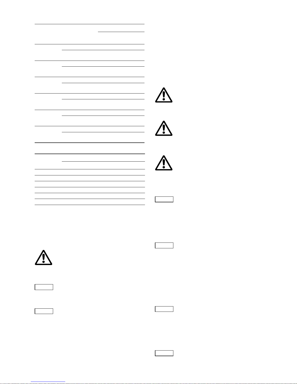
Ball non-return valve
In order for the diaphragm leakage detection to work and to
protect the diaphragms, the gap must be fully deaerated. Dosing
heads with a double diaphragm are equipped with a ball nonreturn valve (T) to prevent air from flowing back during the filling
and deaeration process (2u).
Fig. 7 Contact pressure gauge
2) For dosing heads with a double diaphragm with no contact
pressure gauge (no diaphragm leakage detection), a locking
unit is fitted instead of the contact pressure gauge.
TM03 6452 4506
1p
F
L
M3b
3a 9p 3p2p5p6p2Q 7p
Pos. Components
1p Motor
2p Worm gearing
3p Eccentric
4p Recuperating spring (not with drive size 3)
5p Sliding plug
6p Piston
7p Crank
M Combined overpressure and degassing valve
E Degassing valve
9p Diaphragm protection system (AMS)
Q Dosing diaphragm
2 Dosing head
3a Suction valve
3b Discharge valve
L Stroke-length adjustment knob
F Oil-filling screw with dipstick
TM03 6453 4506
Pos. Components
S Contact pressure gauge
T Ball non-return valve
U Connection piece
T
5u
4u
3u
2)
U
5s
3u
2u
S
6s
Page 16

16
Functional principle of diaphragm leakage detection
The non-return valve and the gap between the diaphragms are
factory-filled with a separating agent (paraffin oil). They are set in
such a way during start-up on the test stand that there is always a
hydraulically separated equilibrium between the valve and
diaphragm gap (the pressure gauge indicates "0" when the pump
is running and when it is stopped).
If one of these diaphragms breaks, the dosing or hydraulic
medium penetrates into the gap between the diaphragms and,
when the ball is removed, into the valve. The system pressure is
therefore impinged on the valve and the contact pressure gauge
is activated. Depending on the design of the system, the
electrically isolated reed contact can trigger an alarm device or
the pump can be switched off.
The contact is triggered at the preset pressure as is shown in the
table below:
Description/use
Set pressure
[bar]
For pumps up to 10 bar
Pressure gauge 0 to 10 bar
1.5
For pumps up to 10 bar
Explosion-proof pressure gauge 0 to 10 bar
1.5
For pumps 16 to 100 bar
Pressure gauge 0 to 100 bar
10
For pumps 16 to 100 bar
Explosion-proof pressure gauge 0 to 100 bar
10
Warning
The contact pressure gauge (Ex) in explosion-
proof version with switch amplifier should be
used if the pump is fitted with an explosion-proof
motor.
Page 17

17
8.2 Dimensional sketches
8.2.1 DMH 251, 252, 253
Fig. 8 DMH 251, 252, 253
Measurements in mm.
TM03 6454 4506
Z1
l / l'
d
b
g
j
c
n
k
f
m
h
a
e
k
9mm
Pos. Description
Z1 For double pump, motor turned by 180 °
l For electrical stroke-length adjustment
l’ For pneumatic stroke-length adjustment
Pump type abcde f gh j k l l’nm
DMH 251 345 336 98 192 160 152 86 432 16 116 250 432 118 180
DMH 252 345 336 98 192 160 152 86 432 16 116 250 432 118 180
DMH 253 368 336 98 192 179 152 86 472 13 124 250 432 118 180
Page 18

18
8.2.2 DMH 254, 255, 257
Fig. 9 DMH 254, 255, 257
Measurements in mm.
TM03 6455 4506
Z1
l / l'
d
b
g
j
c
n
k
f
fx
m
mx
h
a
e
k
9mm
Pos. Description
Z1 For double pump, motor turned by 180 °
fx, mx For double pumps
l For electrical stroke-length adjustment
l’ For pneumatic stroke-length adjustment
Pump type abcdeffxghj kl l’nmmx
DMH 254 436 492 156 252 207 185 260 126 718 10 185 235 413 180 225 300
DMH 255 510 492 156 254 228 185 260 126 869 10 253 235 413 180 225 300
DMH 257 589 553 170 274 280 241 333 129 980 25 262 245 420 195 290 382
Page 19
19
8.3 Weight
8.4 Stroke volume
8.5 Materials
Pump housing material
• Pump housing: Al 226.
AR control unit enclosure
• Upper part of enclosure: PPO blend
• Lower part of enclosure: aluminium.
8.6 Data of contact pressure gauge for diaphragm
leakage detection (optional)
The contact pressure gauge has a reed switch with electrically
isolated contact output, maximum switching power 10 W for DC
current or 10 VA for AC current. The maximum switching voltage
is 100 V, maximum switching current 0.5 A.
The switching function is set up as an NC contact, i.e. if the
diaphragm breaks, the current circuit is interrupted.
The pressure gauge has a 2-metre cable.
9. Installation
9.1 General information on installation
9.2 Installation location
9.2.1 Space required for operation and maintenance
Maintenance work on the dosing head and the valves must be
carried out regularly.
• Provide sufficient space for removing the dosing head and the
valves.
9.2.2 Permissible ambient influences
• Permissible ambient temperature: 0 °C to +40 °C
(for an installation height up to 1000 m above sea level).
• Permissible air humidity: max. relative humidity:
70 % at +40 °C, 90 % at +35 °C.
9.2.3 Mounting surface
The pump must be mounted on a flat surface.
9.3 Mounting
• Mount the pump on a console or pump foundation using four
screws.
Pump type
Dosing head
material
Weight [kg]
Single
pump
Double
pump
DMH 251
PVC, PP, PVDF 11 13
Stainless steel
1.4571, 2.4610
13 17
DMH 252
PVC, PP, PVDF 11 13
Stainless steel
1.4571, 2.4610
13 17
DMH 253
PVC, PP, PVDF 12 17
Stainless steel
1.4571, 2.4610
14 21
DMH 254
PVC, PP, PVDF 27 32
Stainless steel
1.4571, 2.4610
32 42
DMH 255
PVC, PP, PVDF 55 63
Stainless steel
1.4571, 2.4610
65 83
DMH 257
PVC, PP, PVDF 56 88
Stainless steel
1.4571, 2.4610
68 112
Pump type
Stroke volume [cm
3
]
4 bar 10 bar 16 bar 25 bar
DMH 251 — 3.5 3.1 2.9
DMH 252 — 6.4 6.3 —
DMH 253 — 11.3 — —
DMH 254 — 31.6 30 —
DMH 255 — 60 — —
DMH 257 171 131 — —
Warning
Observe the chemical manufacturer's safety
instructions when handling chemicals!
Make sure that the pump is suitable for the actual
dosing medium!
Caution
The resistance of the parts that come into contact
with the media depends on the media, media
temperature and operating pressure. Ensure that
parts in contact with the media are chemically
resistant to the dosing medium under operating
conditions!
Note
Further information on resistance with regard to
the media, media temperature and operating
pressure is available on request.
Warning
Observe the specifications for the installation
location and range of applications described in
section 6. Technical data.
Warning
Faults, incorrect operation or faults on the pump
or system can, for example, lead to excessive or
insufficient dosing, or the permissible pressure
may be exceeded. Consequential faults or
damage must be evaluated by the operator and
appropriate precautions must be taken to avoid
them!
Warning
Risk of hot surfaces!
Pumps with AC motors may become hot.
Allow a minimum space of 100 mm to the fan
cover!
Note
A positive pressure difference of at least 2 bar is
required between the suction valve and the
discharge valve in order for the dosing pump to
operate correctly.
If the total counter-pressure (at the dosing point)
and geodetic height difference between the
suction valve and the dosing point is less than
2 bar (20 m WC), a pressure-loading valve must
be installed immediately before the dosing point.
Note
The pump must be installed in a position where it
is easily accessible during operation and
maintenance work.
Note
The installation site must be under cover!
Do not install outdoors!
Note
The flow must run in the opposite direction to
gravity!
Page 20

20
9.4 Approximate values when using pulsation
dampers
The table below indicates the approximate values and the suction
line length for which suction pulsation dampers are required. The
values apply to 50 Hz operation when water or similar liquids are
dosed.
Caution
Risk of damage to the system!
It is always recommended to use pulsation
dampers for large high-speed pumps!
In particular for pump types with a flow rate
above 1000 l/h (DMH 257), suction and discharge
pulsation dampers should be used directly at the
pump suction and discharge ports of the pump.
The size of the suction and discharge lines
should be adjusted accordingly.
Since the pulsation is influenced by many
factors, a system-specific calculation is
essential. Request a calculation from our
calculation program.
Pump type
Stroke rate
[n/min]
Nominal
width of
suction line
Maximum
length of
suction line
[m]
DMH 251
DMH 2.4-10 14 DN 8 8
DMH 5-10 29 DN 8 8
DMH 13-10 63 DN 8 3
DMH 19-10 96 DN 8 1.5
DMH 24-10 120 DN 8 1
DMH 2.3-16 14 DN 8 8
DMH 4.9-16 29 DN 8 8
DMH 12-16 63 DN 8 3
DMH 18-16 96 DN 8 1.5
DMH 23-16 120 DN 8 1
DMH 2.2-25 14 DN 8 8
DMH 4.5-25 29 DN 8 8
DMH 11-25 63 DN 8 3
DMH 17-25 96 DN 8 1.5
DMH 21-25 120 DN 8 1
DMH 252
DMH 11-10 29 DN 8 8
DMH 24-10 63 DN 8 2
DMH 37-10 96 DN 8 1
DMH 46-10 120 DN 8 1
DMH 10-16 29 DN 8 8
DMH 23-16 63 DN 8 2
DMH 36-16 96 DN 8 1
DMH 45-16 120 DN 8 1
DMH 54-16 144 DN 8 1
DMH 253
DMH 21-10 29 DN 20 8
DMH 43-10 63 DN 20 8
DMH 67-10 96 DN 20 6
DMH 83-10 120 DN 20 4
DMH 100-10 144 DN 20 3
DMH 254
DMH 50-10 26 DN 20 8
DMH 102-10 54 DN 20 8
DMH 143-10 75 DN 20 5
DMH 175-10 92 DN 20 3
DMH 213-10 112 DN 20 1.5
DMH 291-10 153 DN 20 1
DMH 46-16 26 DN 20 8
DMH 97-16 54 DN 20 8
DMH 136-16 75 DN 20 5
DMH 166-16 92 DN 20 3
DMH 202-16 112 DN 20 1.5
DMH 276-16 153 DN 20 1
DMH 255
DMH 194-10 54 DN 20 5
DMH 270-10 75 DN 20 3
DMH 332-10 92 DN 20 1.5
DMH 403-10 112 DN 20 1
DMH 550-10 153 DN 20 1.5
DMH 257
DMH 220-10 28 DN 32 4.5
DMH 440-10 56 DN 32 4.5
DMH 575-10 73 DN 32 3
DMH 750-4 73 DN 32 1.5
DMH 770-10 98 DN 32 1.5
DMH 880-10 112 DN 32 1
DMH 1150-10 146 DN 32 0.5
DMH 1500-4 146 DN 32 0.5
Pump type
Stroke rate
[n/min]
Nominal
width of
suction line
Maximum
length of
suction line
[m]
Page 21

21
9.5 Optimum installation
Fig. 10 Example of optimum installation
9.6 Installation tips
• For easy deaeration of the dosing head, install a ball valve
(11i) with bypass line (back to the dosing tank) immediately
after the discharge valve.
• In the case of long discharge lines, install a non-return valve
(12i) in the discharge line.
Fig. 11 Installation with ball valve and non-return valve
• When installing the suction line, observe the following:
– Keep the suction line as short as possible. Prevent it from
becoming tangled.
– If necessary, use swept bends instead of elbows.
– Always route the suction line up towards the suction valve.
– Avoid loops which may cause air bubbles.
Fig. 12 Installation of suction line
• For non-degassing media with a viscosity similar to water, the
pump can be mounted on the tank (observe the maximum
suction lift).
• Flooded suction preferred.
• For media with a tendency to sedimentation, install the suction
line with filter (13i) so that the suction valve remains a few
millimetres above the possible level of sedimentation.
Fig. 13 Tank installation
• Note for suction-side installation: Depending on the dosing
flow and the line length, it may be necessary to install a
properly sized pulsation damper (4i) immediately before the
pump suction valve.
Fig. 14 Installation with suction-side pulsation damper
• Note for discharge-side installation: Depending on the dosing
flow and the line length, it may be necessary to install a
properly sized pulsation damper (4i) on the discharge side.
TM03 6296 4506
1i
2i
3i
4i
5i
6i
7i
9i
10i
8i
max. 1m
Max. 1 m
Pos. Components
1i Dosing tank
2i Electric agitator
3i Extraction device
4i Suction pulsation damper
5i Dosing pump
6i Relief valve
7i Pressure-loading valve
8i Pulsation damper
9i Measuring glass
10i Injection unit
TM03 6297 4506TM03 6298 4506
11i
12i
TM03 6299 4506
Note
Observe section 9.4 Approximate values when
using pulsation dampers and, if necessary,
request a system-specific calculation from our
calculation program.
TM03 6300 4506
p
10i
6i
13i
4i
Page 22

22
Fig. 15 Installation with discharge-side pulsation damper
• For degassing and viscous media: flooded suction.
• Install a filter in the suction line to prevent the valves from
becoming choked.
• To protect the dosing pump and the discharge line against
excessive pressure build-up, install a relief valve (6i) in the
discharge line.
Fig. 16 Installation with relief valve
With open outflow of the dosing medium or a counterpressure below 2 bar
• Install a pressure-loading valve (7i) immediately before the
outlet or the injection unit.
A positive pressure difference of at least 2 bar must be ensured
between the counter-pressure at the injection point and the
pressure of the dosing medium at the pump suction valve.
• If this cannot be ensured, install a pressure-loading valve (7i)
in the discharge line.
Fig. 17 Installation with pressure-loading valve
• To avoid the siphon effect, install a pressure-loading valve (7i)
in the discharge line and, if necessary, a solenoid valve (14i) in
the suction line.
Fig. 18 Installation to avoid the siphon effect
9.7 Tube / pipe lines
9.7.1 General
9.8 Connecting the suction and discharge line s
• Connect the suction line to the suction valve.
– Install the suction line in the tank so that the foot valve
remains 5 to 10 mm above the bottom of the tank or the
possible level of sedimentation.
• Connect the discharge line to the discharge valve.
Connection of hose lines
• Push the hose firmly on the connection nipple and, depending
on the connection, secure using a connection counterpart or
hose clip.
• Fit the gasket.
• Screw the hose on the valve using the union nut.
Fig. 19 Connection of hose lines
Note
To protect the system, use pulsation dampers (8i)
for rigid piping longer than 2 metres and tubing
longer than 3 metres, depending on pump type
and size.
TM03 6301 4506
Caution
Risk of damage to the system!
It is always recommended to use pulsation
dampers for large high-speed pumps!
Since the pulsation is influenced by many
factors, a system-specific calculation is
essential. Request a calculation from our
calculation program.
TM03 6302 4506TM03 6303 4506
8i
6i
10i
p
7i
p≥ 2 bar
p ≥ 1 bar
TM03 6304 4506
Warning
To protect the dosing system against excessive
pressure build-up, install a relief valve in the
discharge line.
Only use the prescribed line types!
All lines must be free from strain!
Avoid loops and buckles in the tubes!
Keep the suction line as short as possible to
avoid cavitation!
If necessary, use swept bends instead of elbows.
Observe the chemical manufacturer's safety
instructions when handling chemicals!
Make sure that the pump is suitable for the actual
dosing medium!
The flow must run in the opposite direction to
gravity!
Caution
The resistance of the parts that come into contact
with the media depends on the media, media
temperature and operating pressure. Ensure that
parts in contact with the media are chemically
resistant to the dosing medium under operating
conditions!
Warning
All lines must be free from strain!
Only use the prescribed line types!
TM03 6456 4506
14i
p
1
p
2
p2 - p
1
1 bar
>
_
p2-p1 ≥ 1 bar
Page 23

23
Connection of DN 20 pipe lines
• Depending on the pipe material and connection, glue the pipe
(PVC), weld it (PP, PVDF or stainless steel) or press it in
(stainless steel).
• Fit the gasket.
• Screw the pipe on the valve using the union nut.
Fig. 20 Connection of DN 20 pipe lines
Connection of DN 32 pipe lines
• Depending on the pipe material, fit the pipe to the welding
neck flange and weld it (stainless steel) or insert it into the
headed bush and weld it (PP, PVDF).
Fig. 21 Connection of DN 32 pipe lines
9.8.1 Connecting a liquid-heated dosing head (optional)
As an option, liquid-heated dosing heads are available in
stainless steel.
Fig. 22 Liquid-heated dosing head
Required characteristics of heating liquid:
• The heating liquid must not chemically attack stainless steel.
• Maximum permissible pressure: p
max.
= 3 bar.
• Maximum permissible temperature: t
max.
= 100 °C.
10. Electrical connections
Make sure that the pump is suitable for the electricity supply on
which it will be used.
10.1 Electric servomotor (optional)
To connect the servomotor to the power supply, see the
installation and operating instructions for the servomotor.
10.2 Electronic preselection counter (optional)
To connect the preselection counter to the power supply, see
the installation and operating instructions for the counter.
10.3 Electrically heated dosing head (optional)
Fig. 23 Electrically heated dosing head
• To connect the temperature controller to the power supply,
see the installation and operating instructions for the electric
temperature controller.
Fig. 24 Temperature controller
TM03 6457 4506TM03 6458 4506TM03 6459 4506
Pos. Components
2f Dosing head, liquid-heated
2f1 Hose nipple, DN 10 connection
Ø10
40
2f1
2f
Warning
Electrical connections must only be carried out
by qualified personnel!
Disconnect the power supply before connecting
the power supply cabl e and the rel ay co ntac ts!
Observe the local safet y regu latio ns!
The pump housing must only be opened by
personnel authorised by Grundfos Alldos!
Protect the cable connections and plugs against
corrosion and humidity.
Only remove the protective caps from the
sockets that are being used.
TM03 6460 4506
Pos. Component
2e Dosing head, electrically heated
TM03 6461 4506
Pos. Connections
2e1 Sensor
2e2 Heating
2e3 Power supply
2e
2e1
2e2
2e3
Page 24

24
10.4 Diaphragm controller (optional)
Fig. 25 Diaphragm controller
10.5 Connecting the power supply cable
• Do not switch on the power supply until you are ready to start
the pump.
10.5.1 Versions with mains plug
• Insert the mains plug in the mains socket.
10.5.2 Versions without mains plug
• Connect the motor to the power supply in accordance with
local electrical installation regulations and the connection
chart on the terminal box cover.
11. Start-up / shutdown
11.1 Initial start-up / subsequent start-up
11.1.1 Checks before start-up
• Check that the rated voltage stated on the pump nameplate
corresponds to the local conditions!
• Check that all connections are secure and tighten,
if necessary.
• Check that the dosing head screws are tightened with the
specified torque and tighten, if necessary.
• Check that all electrical connections are correct.
• Cross-tighten the dosing head screws using a torque wrench.
Torques
11.1.2 Oil filling
1. Slacken and remove the oil-filling screw (F).
2. Slowly add the hydraulic oil supplied with the pump through
the oil-filling opening (F) until the oil reaches the mark on the
oil dipstick.
3. Set the stroke-length adjustment knob (L) to "0".
Warning
Explosion-proof pumps with diaphragm leakage
detection are fitted with a contact pressure gauge
in explosion-proof version.
The pressure gauge must be earthed.
Connecting the earth cable (4u), see fig. 25.
TM03 6453 4506
Pos. Com ponents
S Contact pressure gauge
5s Union nut
6s Contact output
T Ball non-return valve
U Connection piece
2u Deaeration screw
3u O-rings
4u Connection for earth cable
5u Union nut
* 2) or locking unit (instead of contact pressure gauge
and its connection)
Warning
Disconnect the power supply before connecting
the power supply cable!
Before connecting the power supply cable, check
that the rated voltage stated on the pump
nameplate corresponds to the local conditions!
Do not make any changes to the power supply
cable or plug!
Caution
The assignment between the plug-and-socket
connection and the pump must be labelled
clearly (e.g. by labelling the socket outlet).
Caution
The pump can be automatically started by
connecting the power supply!
Warning
The pump must be connected to an external
clearly labelled mains switch with a minimum
contact gap of 3 mm in all poles.
T
5u
4u
3u
2)
U
5s
3u
2u
S
6s
Warning
The specified enclosure class can only be
ensured if the power supply cable is connected
with the same degree of protection.
Caution
Observe the direction of rotation!
To protect the motor, install a motor protecting
switch or motor contactor, and set the bimetal
relay to the rated motor current for the available
voltage and frequency.
Warning
When dosing dangerous media, observe the
corresponding safety precautions!
Wear protective clothing (gloves and goggles)
when working on the dosing head, connections
or lines!
Before removing the dosing head, valves and
lines, empty any remaining medium in the dosing
head into a drip tray by carefully unscrewing the
suction valve.
The pump housing must only be opened by
personnel authorised by Grundfos Alldos!
Repairs must only be carried out by authorised
and qualified personnel!
Caution
Observe the flow direction of valves (indicated by
an arrow on the valve)!
Only tighten plastic valves by hand.
Pump type
Torque
[Nm]
DMH 251, 10 bar 8-10
DMH 251, 16 bar 10-12
DMH 251, 25 bar 13-15
DMH 252 8-10
DMH 253 10-12
DMH 254 50-54
DMH 255 50-54
DMH 257 50-54
Note
The pump is factory-checked, and the oil is
drained for shipping purposes. Before start-up,
add the special oil supplied with the pump.
The piston flange is filled with oil for easy startup. The stroke-length adjustment knob must only
be adjusted if the gear oil has been added,
otherwise the oil will leak from the piston flange.
Page 25

25
11.1.3 Filling the dosing head for the initial start-up for
systems without flooded suction
As assisting suction for systems without flooded suction, you can
fill the dosing head with dosing medium before the initial start-up:
1. Unscrew the discharge valve (3b).
2. Add the dosing medium to the dosing head (2).
3. Screw the discharge valve (3b) back in.
11.2 Start-up / subsequen t start-up of DMH 251, 252
and 253
Fig. 26 Start-up of DMH 251, 252 and 253
1. Connect the electrical power supply.
2. Depending on the installation, start the pump, where possible,
without counter-pressure.
See installation example for easy deaeration of the dosing head
in section
9. Installation.
3. Set the stroke-length adjustment knob (L) to 0 %.
4. Let the pump run for approx. 5 minutes.
5. Check the oil level.
– Set the stroke-length adjustment knob (L) to 40 %.
– Let the pump run for approx. 10 minutes with a stroke-length
setting of 40 %.
– Switch off the pump, check the oil level and add oil,
if necessary.
– Refit the oil-filling screw (F).
6. Deaerate the piston flange.
– Set the stroke-length adjustment knob (L) to 15 %.
– Loosen the degassing valve (E) by one turn to the left.
– Let the pump run for approx. 5 minutes.
– Re-tighten the degassing valve (E).
The pump is now ready for operation.
After start-up
Torques
11.3 Start-up / subs equent start-up of DMH 254, 255
and 257
Fig. 27 Start-up of DMH 254, 255 and 257
Warning
When dosing dangerous media, observe the
corresponding safety precautions!
Wear protective clothing (gloves and goggles)
when working on the dosing head, connections
or lines!
Note
Observe the flow direction of the discharge valve
(indicated by an arrow on the valve)!
TM03 6462 4506
Pos. Components
1q Dosing head screws
2 Dosing head
3b Discharge valve
E Degassing valve
F Oil-filling screw with dipstick
L Stroke-length adjustment knob
1l Cover for stroke-length adjustment knob
M Pressure relief valve
L
F
1l
2
M M1qE
3b
Warning
Risk of injury caused by squirting oil!
Oil may squirt from the oil deaeration when the
pump is running. Do not completely unscrew the
oil deaeration screw.
Wear protective clothing (gloves and goggles)
when working on the dosing head, connections
or lines!
Note
Rod length of oil dipstick: 27 mm.
Immersion depth to marking: approx. 5 mm.
Note
Check the oil level at least every two weeks and
add oil, if necessary.
Only use original Grundfos Alldos gear oil!
For product number, see service instructions.
Pump type Version Description
DMH 251 Single/double
1.3 l white oil
(Paraffin 55 DAB7)
DMH 252, 10 bar Single/double
1.3 l white oil
(Paraffin 55 DAB7)
DMH 252, 16 bar Single/double 1.3 l DHG 68
DMH 253 Single/double 1.3 l DHG 68
Caution
After initial start-up and after each time the
diaphragm is changed, tighten the dosing head
screws.
After approximately 6-10 operating hours or
two days, cross-tighten the dosing head screws
using a torque wrench.
Pump type
Torque
[Nm]
DMH 251, 10 bar 8-10
DMH 251, 16 bar 10-12
DMH 251, 25 bar 13-15
DMH 252 8-10
DMH 253 10-12
TM03 6463 4506
Pos. Components
1q Dosing head screws
2 Dosing head
3b Discharge valve
F Oil-filling screw with dipstick
L Stroke-length adjustment knob
1l Cover for stroke-length adjustment knob
M Pressure relief valve
L
F
1l
2
M M
1q
3b
Page 26

26
1. Connect the electrical power supply.
2. Depending on the installation, start the pump, where possible,
without counter-pressure.
See installation example for easy deaeration of the dosing head
in section
9. Installation.
3. Set the stroke-length adjustment knob (L) to 0 %.
4. Let the pump run for approx. 5 minutes.
5. Check the oil level.
– Set the stroke-length adjustment knob (L) to 40 %.
– Let the pump run for approx. 10 minutes with a stroke-length
setting of 40 %.
– Switch off the pump, check the oil level and add oil,
if necessary.
– Refit the oil-filling screw (F).
The pump is now ready for operation.
After start-up
Torques
11.4 Setting the pressure relief valve
The pressure relief valve is set to the pressure given by the
customer, or to the rated pressure (maximum counter-pressure).
The opening pressure can be set to a lower value by the
customer.
Opening pressure of the pressure relief valve
Setting the opening pressure
• To set the operating pressure, a pressure gauge must be
installed in the discharge line and an isolating valve must be
installed after the pressure gauge.
• To set the pressure relief valve, use a screwdriver.
Fig. 28 Setting the opening pressure
Set the pressure relief valve as follows:
1. Close the isolating valve after the pressure gauge.
2. Remove the cover (1m) from the pressure relief valve.
3. Start the pump.
4. Using a screwdriver, slowly turn the adjusting screw (2m) of
the pressure relief valve counter-clockwise until the desired
opening pressure is obtained.
Fig. 29 Setting the pressure relief valve
5. Replace the cover of the pressure relief valve.
6. Open the isolating valve after the pressure gauge.
Warning
Risk of injury caused by squirting oil!
Oil may squirt from the oil deaeration when the
pump is running. Do not completely unscrew the
oil deaeration screw.
Wear protective clothing (gloves and goggles)
when working on the dosing head, connections
or lines!
Note
Rod length of oil dipstick: 35 mm.
Immersion depth to marking: approx. 5 mm.
Note
Check the oil level at least every two weeks and
add oil, if necessary.
Only use original Grundfos Alldos gear oil!
For product number, see service instructions.
Pump type Version Description
DMH 254 Single 3.5 l DHG 68
DMH 254 Double 4.5 l DHG 68
DMH 255 Single 3.5 l DHG 68
DMH 255 Double 4.5 l DHG 68
DMH 257 Single 5.5 l DHG 68
DMH 257 Double 7.5 l DHG 68
Caution
After initial start-up and after each time the
diaphragm is changed, tighten the dosing head
screws.
After approximately 6-10 operating hours or
two days, cross-tighten the dosing head screws
using a torque wrench.
Pump type
Torque
[Nm]
DMH 254 50-54
DMH 255 50-54
DMH 257 50-54
Rated pressure of the pump
[bar]
Opening pressure of the
pressure relief valve
[bar]
45
10 13
16 18
25 28
TM03 6464 4506TM03 6465 4506
Caution
Risk of damage to the pump or system!
When blocked, the pressure relief valve does not
work properly and can produce pressures of
several hundred bar in the pump or system.
Do not block the pressure relief valve during
adjustments!
2m
1m
Page 27

27
11.5 Zero point adjustments
11.5.1 Adjusting the zero point for system pressures up to
100 bar
The zero point of the dosing pump is factory-set to a slightly lower
counter-pressure than the rated pressure of the pump. If the
operating counter-pressure deviates considerably from this value,
an adjustment of the zero point will ensure more precise values.
Counter-pressure at the factory-set zero point of the pump
11.5.2 Adjusting the zero point
Fig. 30
Adjusting the zero point
1. Fit a measuring device on the suction side, for instance place
the suction line in a graduated measuring beaker.
2. Set the dosing flow to 15 %.
3. Remove the cover (1l) from the stroke-length adjustment knob
(L).
4. Use a screwdriver to loosen the locking screw (2l) by
approximately 2 turns.
5. Switch on the pump.
6. Slowly turn the stroke-length adjustment knob towards the
zero point until the dosing (the liquid level falls) stops in the
measuring device.
7. Switch off the pump.
8. Set the scale ring (4l) to zero.
– Loosen the screw (3l) in the scale ring (4l) slightly using an
hexagon key, M3.
– Turn the scale ring (4l) until both "0" are the same on the
scale and scale ring.
– Tighten the screw (3l).
9. Depending on the application, tighten the locking screw (2l) so
that the stroke-length adjustment knob can still be turned/
cannot be turned any more.
10.Replace the cover (1l).
11.6 Operating the pump
11.7 Shutdown
11.7.1 Switching off / uninstalling
1. Switch off the pump and disconnect it from the power supply.
2. Depressurise the system.
3. Take suitable steps to ensure that the returning dosing
medium is safely collected.
4. Carefully remove all lines.
5. Uninstall the pump.
11.7.2 Cleaning
1. Rinse all parts that have come into contact with the medium
very carefully:
– lines
– valves
– dosing head
– diaphragm.
2. Remove any trace of chemicals from the pump housing.
11.7.3 Storage
Storage of the pump:
1. After cleaning (see section
11.7.2 Cleaning), carefully dry all
parts and reinstall the dosing head and valves, or
2. change the valves and diaphragm.
See section
13. Maintenance.
11.7.4 Disposal
Disposal of the pump:
• After cleaning (see section
11.7.2 Cleaning), dispose of the
pump in accordance with the relevant regulations.
12. Operation
12.1 Switching on/off
• To start the pump, switch on the power supply.
• To stop the pump, switch off the power supply.
Rated pressure of the pump
[bar]
Counter-pressure at the
factory-set zero point
[bar]
10 3
16 3
25 10
TM03 6466 4506
Pos. Components
L Stroke-length adjustment knob
1l Cover
2l Locking screw
3l Screw
4l Scale ring
Warning
When dosing dangerous media, observe the
corresponding safety precautions!
Wear protective clothing (gloves and goggles)
when working on the dosing head, connections
or lines!
Always adjust the value with the discharge line
connected and with operating counter-pressure.
3l 2l 1l
4l
3l
L
Note
When operating the pump, see sections
12. Operation and 13. Maintenance and,
if necessary, section 14. Fault finding chart.
Warning
Wear protective clothing (gloves and goggles)
when working on the dosing head, connections
or lines!
Do not allow any chemicals to leak from the
pump. Collect and dispose of all chemicals
correctly!
Note
If possible, rinse the dosing head before shutting
down the pump, e.g. by supplying it with water.
Caution
Before switching on the pump, check that it is
installed correctly. See sections 9. Installation
and 11. Start-up / shutdown.
Page 28

28
12.2 Setting the dosing capacity
Fig. 31 Setting the dosing capacity
12.2.1 Setting the dosing flow and locking the stroke-length
adjustment knob
1. Remove the cover (1l) from the stroke-length adjustment knob
(L).
2. Use a screwdriver to loosen the locking screw (2l) by
approximately 2 turns.
3. Increase or
reduce the dosing flow while the pump is running.
– Slowly turn the stroke-length adjustment knob to the left or
right to set the desired dosing volume.
4. Depending on the application, tighten the locking screw (2l) so
that the stroke-length adjustment knob can still be turned/
cannot be turned any more.
5. Replace the cover (1l).
12.3 Using the AR control unit (optional)
When using the AR control unit, observe the installation and
operating instructions for the "AR control unit" in addition to the
instructions in this manual.
12.4 Electric servomotor (optional)
To operate the servomotor, see the installation and operating
instructions for the servomotor.
12.5 Electronic preselection counter (optional)
To operate the preselection counter, see the installation and
operating instructions for the counter.
12.6 Electrically heated dosing head (optional)
To operate the temperature controller, see the installation and
operating instructions for the temperature controller.
13. Maintenance
13.1 General notes
13.2 Diaphragm leakage control for diaphrag m
leakage detection
If a diaphragm leakage (MLS) has been detected, first of all check
whether an error has been displayed, as different external factors
such as the heating of dosing or hydraulic medium can cause the
cracked medium between the diaphragms to be displaced into the
valve, thereby causing an error to occur.
Checks after a diaphragm leakage detection:
1. Briefly open the deaeration screw (2u) and then close it again.
2. Switch on the pump.
3. If, after a short period of time, a diaphragm leakage is
detected again, a diaphragm has broken.
Fig. 32 Dosing head with double diaphragm
TM03 6466 4506
Pos. Com ponents
L Stroke-length adjustment knob
1l Cover
2l Locking screw
3l Screw
4l Scale ring
Caution
The pump cannot be operated if the stroke-length
adjustment knob is fully open! Depending on the
pump adjustment, this value may already be
lower than 100 % on the scale for system
pressures higher than 100 bar.
Open the stroke-length adjustment knob
completely and then close by approx. 10 % in
order to set the dosing flow to 100 %.
3l 2l 1l
4l
3l
L
Warning
When dosing dangerous media, observe the
corresponding safety precautions!
Wear protective clothing (gloves and goggles)
when working on the dosing head, connections
or lines!
The pump housing must only be opened by
personnel authorised by Grundfos Alldos!
Repairs must only be carried out by authorised
and qualified personnel!
Switch off the pump and disconnect it from the
power supply before carrying out maintenance
work and repairs!
Before removing the dosing head, valves and
lines, empty any remaining medium in the dosing
head into a drip tray by carefully unscrewing the
suction valve.
Caution
Observe the flow direction of valves (indicated by
an arrow on the valve)!
Only tighten plastic valves by hand.
Caution
After a diaphragm breakage, replace the
diaphragms and clean the non-return valve, see
section 13.7 Replacing the diaphragm for dosing
head with double diaphragm.
TM03 6467 4506
Pos. Compo nents
S Contact pressure gauge
T Ball non-return valve
U Connection piece
1u Filling screw
2u Deaeration screw
T
U
2u
S
1u
Page 29
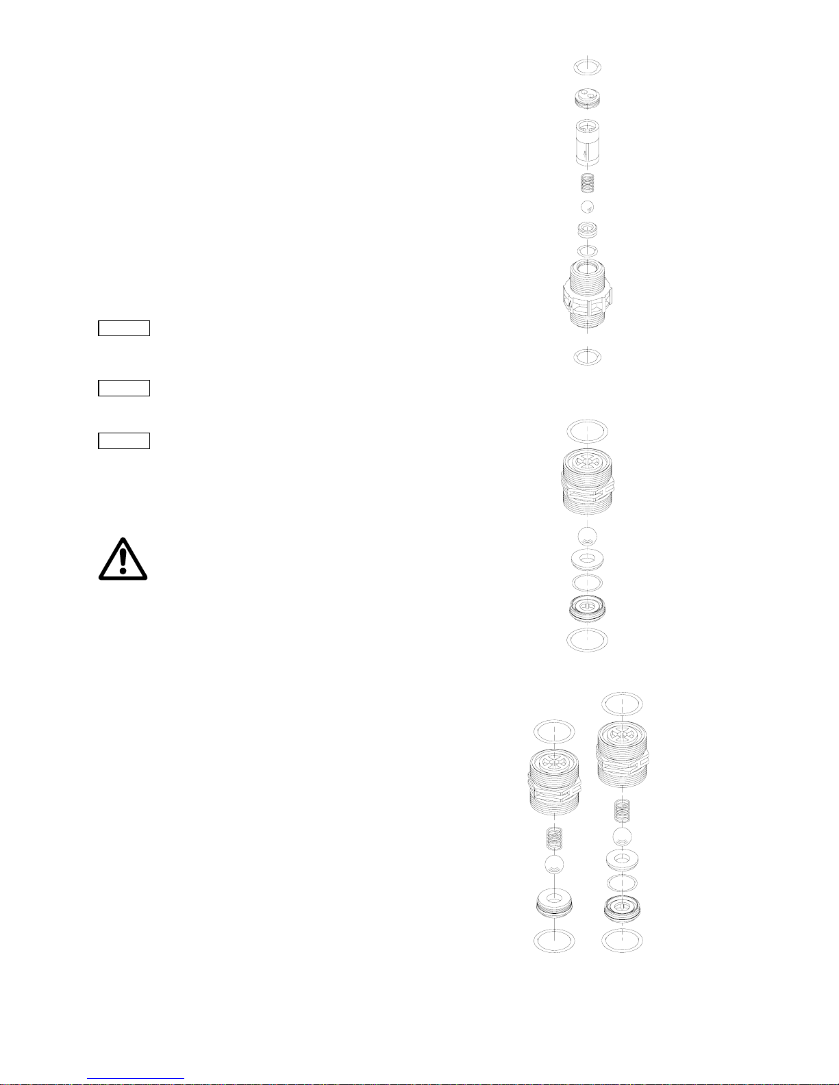
29
13.3 Cleaning and maintenance intervals
Checking the oil level
• Check the oil level every two weeks and add oil, if necessary.
Cleaning the valves
• At least every 12 months or after 4,000 operating hours.
• If the pump does not perform.
• In the event of a fault.
Clean the valves and replace, if necessary (for stainless-steel
valves: inner valve parts).
Changing diaphragms and gear oil
• At least every 12 months or after 8,000 operating hours,
change the dosing medium and gear oil.
• In dusty installation sites, change the gear oil every
3,000 operating hours.
Cleaning the ball non-return valve of the double diaphragm
• After a diaphragm breakage, remove the ball non-return valve
immediately and clean it.
13.4 Checking the oil level
13.5 Cleaning the suction and discharge valves
DN 8 valve
• Screwed connection 5/8"
• Stainless steel or plastic
• Spring-loaded (optional).
DN 20 valve (valve for suction side only), with adapter
• Screwed connection 1 1/4"
• Plastic.
DN 20 valve
• Screwed connection 1 1/4"
• Stainless steel or plastic
• Spring-loaded (optional).
DN 32 valve (for 60 Hz operation, suction side only),
with adapter
• Flange connection
• Stainless steel or plastic.
Clean the suction and discharge valves as follows:
1. Unscrew the valves.
2. Unscrew the screw parts and valve set using round pliers.
3. Dismantle the inner part (seat, O-ring, balls, ball cages and,
if present, spring).
4. Clean all parts. Replace faulty parts by new ones.
5. Re-assemble the valve.
6. Replace the O-rings by new ones. Refit the valve.
Fig. 33 Stainless-steel or plastic DN 8 valve, spring-loaded
as an option
Fig. 34 Plastic DN 20 valve
Fig. 35 Stainless-steel or plastic DN 20 valve, spring-loaded
as an option
Note
Only clean the ball non-return valve after a
diaphragm breakage!
Caution
Check the oil level at least every two weeks and
add oil, if necessary.
Note
Rod length of oil dipstick:
DMH 251-253: 27 mm.
DMH 254-257: 35 mm.
Immersion depth to marking: approx. 5 mm.
Warning
Wear protective clothing (gloves and goggles)
when working on the dosing head, connections
or lines!
Before removing the dosing head, valves and
lines, empty any remaining medium in the dosing
head into a drip tray by carefully unscrewing the
suction valve.
TM03 6468 4506TM03 6469 4506TM03 6470 4506
2)1)
Stainless
steel
Plastic
Page 30

30
Fig. 36 DN 32 valve, suction side and discharge side
13.6 Replacing the diaphragm and gear oil for dosing
head with single diaphragm (no diaphragm
leakage detection)
13.6.1 Drain gear oil
Fig. 37
Drain gear oil
1. Unscrew the locking screw (B) and collect the gear oil in a
container.
2. Screw the locking screw (B) and the new gasket (1b) back in
and tighten securely.
13.6.2 Removing the dosing head
1. Close the suction and discharge lines and loosen the suction
and discharge valve connections.
2. Loosen the six dosing head screws (1q with 2q).
3. Remove the dosing head (2).
13.6.3 Replacing a single diaphragm (no diaphragm leakage
detection)
• Remove the diaphragm and fit a new diaphragm (Q) on the
suction side. See fig. 38.
Fig. 38 Replacing a single diaphragm
TM03 6471 4506
Caution
The O-rings must be correctly placed in the
specified groove.
Observe the flow direction (indicated by an arrow
on the valve)!
Only tighten plastic valves by hand.
Warning
Wear protective clothing (gloves and goggles)
when working on the dosing head, connections
or lines!
The dosing diaphragm should be replaced with
each gear oil change.
Before removing the dosing head, valves and
lines, empty any remaining medium in the dosing
head into a drip tray by carefully unscrewing the
suction valve.
Note
Only use original Grundfos Alldos gear oil!
For product number, see service instructions.
Pump type Version Description
DMH 251 Single/double
1.3 l white oil
(Paraffin 55 DAB7)
DMH 252, 10 bar Single/double
1.3 l white oil
(Paraffin 55 DAB7)
DMH 252, 16 bar Single/double 1.3 l DHG 68
DMH 253 Single/double 1.3 l DHG 68
DMH 254 Single 3.5 l DHG 68
DMH 254 Double 4.5 l DHG 68
DMH 255 Single 3.5 l DHG 68
DMH 255 Double 4.5 l DHG 68
DMH 257 Single 5.5 l DHG 68
DMH 257 Double 7.5 l DHG 68
Note
Collect the gear oil in a container and dispose of
it correctly.
Discharge side
Suction side
TM03 6472 4506
Pos. Compo nents
B Locking screw
1b Gasket
F Oil-filling screw with dipstick
L Stroke-length adjustment knob
Caution
Risk of leaking oil and damage caused by oil
loss!
For each oil change, a new flat gasket (1b) must
be fitted!
TM03 6473 4506
Pos. Compo nents
1q Dosing head screw
2q Intermediate disk
2 Dosing head
Q Diaphragm
1b
L
F
B
1q
Q
2
2q
Page 31

31
13.6.4 Fitting the dosing head
• Fit the dosing head and cross-tighten the dosing head screws
(1q with 2q) using a torque wrench.
13.6.5 Filling with gear oil
1. Check that the locking screw (B) is tightened.
2. Slacken and remove the oil-filling screw (F).
3. Set the stroke-length adjustment knob (L) to "0".
4. Slowly add the hydraulic oil through the oil-filling opening (F)
until the oil reaches the mark on the oil dipstick.
5. Wait 30 minutes.
6. Let the pump run for approx. 5 minutes with a stroke-length
setting of 0 %.
7. Let the pump run for approx. 10 minutes with a stroke-length
setting of 40 %.
13.6.6 Checking the oil level
1. Switch off the pump, check the oil level and add oil,
if necessary.
2. Refit the oil-filling screw (F).
Torques
13.7 Replacing the diaphragm for dosing h ead with
double diaphragm
13.7.1 Removing the dosing head
1. Close the suction and discharge lines and loosen the suction
and discharge valve connections.
2. Loosen the six dosing head screws (1q with 2q).
3. Remove the dosing head (2).
13.7.2 Replacing a double diaphragm
1. Clean the intermediate disk (3q), sealing rings (4q) and
covering rings (5q). After a diaphragm breakage, replace the
parts by new ones.
2. Remove both clamping sleeves (6q) slightly using pliers.
After a diaphragm breakage, replace the parts by new ones.
3. Measure the outer wall thickness of both new diaphragms
(Q1 and Q2): s1
(Q1)
< s2
(Q2)
.
Fig. 39 Installation of diaphragm
1) The shape of the diaphragm varies depending on pump type.
4. Fit both new diaphragms (Q1 and Q2) and the parts (3q - 5q)
in the correct order, as is shown in the diagrams (the clamping
sleeves (6q) are used for centring purposes).
Note
See section 11. Start-up / shutdown for
subsequent start-up!
Caution
Risk of leaking oil and damage caused by oil
loss!
For each oil change, a new flat gasket (1b) must
be fitted!
Caution
After initial start-up and after each time the
diaphragm is changed, tighten the dosing head
screws.
After approximately 6-10 operating hours or
two days, cross-tighten the dosing head screws
using a torque wrench.
Pump type
Torque
[Nm]
DMH 251, 10 bar 8-10
DMH 251, 16 bar 10-12
DMH 251, 25 bar 13-15
DMH 252 8-10
DMH 253 10-12
DMH 254 50-54
DMH 255 50-54
DMH 257 50-54
Warning
Wear protective clothing (gloves and goggles)
when working on the dosing head, connections
or lines!
The dosing diaphragm should be replaced with
each gear oil change.
Before removing the dosing head, valves and
lines, empty any remaining medium in the dosing
head into a drip tray by carefully unscrewing the
suction valve.
Note
Only use original Grundfos Alldos gear oil!
For product number, see service instructions.
TM03 6474 4506
Pos. Components
1q Dosing head screw
2q Intermediate disk
2 Dosing head
Q1/Q2
See fig. 40
3q - 5q
Caution
Observe correct installation of diaphragms (Q1
and Q2)! See fig. 40.
Fit the thinner diaphragm (Q1) on the dosing side
and the thicker diaphragm (Q2) on the oil side/
pump side!
1q
2
2
q
3q - 5q Q2Q1
1)
s1 < s
2
Page 32

32
Fig. 40 Diaphragm on dosing-head side
13.7.3 Fitting the dosing head
• Fit the dosing head and cross-tighten the dosing head screws
using a torque wrench.
13.7.4 Filling the double diaphragm with separating agent
Pump with double diaphragm: After the diaphragm has been
replaced, refill the separating agent between the diaphragms.
Fig. 41 Dosing head with double diaphragm
1. Set the stroke-length adjustment knob of the pump to 0 %.
2. Open the filling screw (1u) and deaeration screw (2u) by one
turn.
3. Connect the filling hose to the nipple of the filling screw (1u)
and, using the dosing syringe, inject the correct amount of
paraffin oil that is specified in the table below.
4. Close the filling screw (1u), but leave the deaeration screw
(2u) open.
5. Start the pump with a system counter-pressure and strokelength setting of 40 %.
6. Only close the deaeration screw (2u) when the separating
agent stops flowing (after 5 to 10 minutes).
Quantity of paraffin oil required for dosing pumps with
a double diaphragm (per do sing head)
For ordering data for double-diaphragm filling components, see
service instructions.
TM03 6475 4506
Pos. Com ponents
S Contact pressure gauge (installation position)
Q1 Diaphragm on dosing-head side
Q2 Diaphragm on oil side/pump side
3q Intermediate disk
4q Sealing rings
5q Covering rings
6q Clamping sleeves
Caution
The paraffin oil between the diaphragms (Q) is
connected via the clamping sleeves (6q) to the
contact pressure gauge (S) in order to fill and
activate the diaphragm leakage detection. The oil
is able to pass between the diaphragms through
the slits in the clamping sleeves and the slits in
the intermediate disk.
The clamping sleeves (6q) must therefore be
installed in such a way that the slits in the
clamping sleeve face the slits in the intermediate
disk (3q). See fig. 40.
Note
See section 11. Start-up / shutdown for
subsequent start-up!
Caution
After a diaphragm has broken, the ball non-return
valve must be cleaned before the diaphragm is
filled with separating agent. Only clean the ball
non-return valve after a diaphragm breakage!
2 5q4q3q4q5q Q2Q1
6q
3q
S
TM03 6467 4506
Pos. Compo nents
S Contact pressure gauge
T Ball non-return valve
U Connection piece
1u Filling screw
2u Deaeration screw
Note
After a few operating hours, especially if the
pressure of the pressure gauge is increasing,
deaerate the double diaphragm again.
Pump type
Filling quantity
[ml]
DMH 251-253 4
DMH 254 6
DMH 255 8
DMH 257 10
T
U
2u
S
1u
Page 33

33
13.7.5 Filling with gear oil
1. Check that the locking screw (B) is tightened.
2. Slacken and remove the oil-filling screw (F).
3. Set the stroke-length adjustment knob (L) to "0".
4. Slowly add the hydraulic oil through the oil-filling opening (F)
until the oil reaches the mark on the oil dipstick.
5. Wait 30 minutes.
6. Let the pump run for approx. 5 minutes with a stroke-length
setting of 0 %.
7. Let the pump run for approx. 10 minutes with a stroke-length
setting of 40 %.
13.7.6 Checking the oil level
1. Switch off the pump, check the oil level and add oil,
if necessary.
2. Refit the oil-filling screw (F).
Torques
13.7.7 Cleaning the ball non-return valve
Fig. 42
Contact pressure gauge
Removing the ball non-return valve and contact pressure
gauge
1. For pumps and pressure gauges in explosion-proof version,
unscrew the earth cable (4u).
2. Hold the connection piece (U) with a screwdriver and unscrew
the union nut (5u).
3. Unscrew the ball non-return valve (T) from the dosing head.
Cleaning the ball non-return valve
Fig. 43
Ball non-return valve
1. Unscrew the screw part (t6) using round pliers.
2. Clean all parts. Replace faulty parts by new ones.
3. Re-assemble the ball non-return valve.
4. Refit the ball non-return valve (T).
5. Screw the contact pressure gauge (S) and connection piece
(U) back on.
6. For pumps and pressure gauges in explosion-proof version,
screw the earth cable (4u) back on.
Caution
Risk of leaking oil and damage caused by oil
loss!
For each oil change, a new flat gasket (1b) must
be fitted!
Caution
After initial start-up and after each time the
diaphragm is changed, tighten the dosing head
screws.
After approximately 6-10 operating hours or
two days, cross-tighten the dosing head screws
using a torque wrench.
Pump type
Torque
[Nm]
DMH 251, 10 bar 8-10
DMH 251, 16 bar 10-12
DMH 251, 25 bar 13-15
DMH 252 8-10
DMH 253 10-12
DMH 254 50-54
DMH 255 50-54
DMH 257 50-54
Note
Only clean the ball non-return valve after
a diaphragm breakage!
TM03 6453 4506
T
5u
4u
3u
2)
U
5s
3u
2u
S
6s
Pos. Components
S Contact pressure gauge
5s Union nut
6s Contact output
T Ball non-return valve
U Connection piece
2u Deaeration screw
3u O-rings
4u Connection for earth cable
5u Union nut
* 2) or locking unit (instead of contact pressure gauge
and its connection)
TM03 6476 4506
Pos. Components
t1 O-ring
t2 Ball non-return valve body
t3 Ball
t4 Spring sheath
t5 Pressure spring
t6 Screw part
t7 O-ring
Caution
Tighten the ball non-return valve and connection
piece by hand only.
t7
t6
t5
t4
t3
t1
t2
t1
Page 34

34
14. Fault finding chart
Warning
Actions that are taken to correct faults on the pump and that are not described in this manual, must only be carried
out by personnel authorised by Grundfos Alldos!
Fault Diagnosis Cause Remedy
No dosing flow
even at a low
counter-pressure.
(Pump is running
without any noise).
No motor sound or vibrations.
Fan is not rotating.
Motor is not running.
Connect the power supply or
replace the motor, if blown.
When the oil-filling screw (F) is
removed, use the dipstick to observe
a calm oil surface. There is no
"sloshing".
Motor runs, but the eccentric shaft is
not rotating. No piston movement.
Spiral pin or motor shaft broken.
Remove the motor and eccentric
shaft. Replace damaged parts.
Oil level too low. See oil dipstick (F).
No reaction of the overpressure
valve if the suction line is closed.
Not enough oil in the pump. Air is
penetrating the piston flange through
the control holes.
Fill in oil. Deaerate the pump, see
section
11. Start-up / shutdown.
No dosing flow on the discharge
side.
Dosing head is not filled. Suction line
empty. Tank empty.
Deaerate the dosing head.
Fill/exchange the tank on the
suction side.
No dosing flow
even at a low
counter-pressure.
(Pump is running
noisily although the
overpressure valve
reacted).
The overpressure valve reacts
independently of the dosing flow
adjustment (10 % to 100 %).
Valve on discharge side closed. Open the valve.
Counter-pressure is higher than the
adjusted pressure at the overpressure
valve.
Adjust the overpressure valve
higher, but only if the pump is
designed for this. Never block the
overpressure valve.
Discharge valve is installed in the
opposite direction of the flow. Observe
the arrow on the valve.
Install the discharge valve
correctly.
The diaphragm protection system
(AMS) responds.
The overpressure valve reacts
independently of the dosing flow
adjustment (10 % to 100 %).
Valve on suction side closed. Open the valve.
Suction filter obstructed.
Clean the suction filter.
Replace, if necessary.
Suction valve jammed (does not open).
Dismantle and check the suction
valve.
Suction valve has a too strong spring.
Use the fitting spring, or use
double ball valve for checking.
Suction valve is installed in the
opposite direction of the flow.
Observe the arrow on the valve.
Install the suction valve correctly.
The diaphragm protection system
(AMS) responds.
The overpressure valve reacts at
100 % dosing flow.
When reducing the flow ~10 % to
20 %, the overpressure valve does
not react any more.
Dosing head is not completely
deaerated.
Fill the dosing head completely.
Pump is cavitating (dosing liquid with
too high viscosity; dosing liquid with
too high steam pressure at operating
temperature = degassing of the liquid;
suction lift too high; wrong design of
the system on suction side).
Use a gear with a low stroke
number; use valves with bigger
nominal width; realise positive inlet
pressure.
Diaphragm broken (not enough oil in
the enclosure of the pump; piston
flange).
Clean and grease well all parts
using oil according to regulations.
Then install a new diaphragm.
Pump does not
dose or pressure
relief valve opens.
Discharge valve of pump is clogged or
ball guide in the valve is worn due to
corrosive or abrasive media.
Uninstall the discharge valve.
Dismantle and clean, or if the bars
of the ball guide are worn, replace
the valve.
Page 35

35
Dosing flow too
small.
Suction valve: During the discharge
stroke, the dosing liquid flows back
into the suction line.
Discharge valve: During the suction
stroke, the dosing liquid flows back
into the dosing head.
The pump takes in less.
Suction/discharge valves dirty or leaky. Clean or replace valves.
Dosing flow depends very much on
the pressure.
If the counter-pressure is low, the
dosing flow increases considerably.
If the stroke frequency rises, the
dosing flow increases excessively.
Too much clearance between piston
and slide valve, or the stroke
frequency of the pump is too low (too
much slip).
Replace the piston and piston slide
valves. Use other hydraulic oil with
a higher viscosity (mainly for
frequency converter operation and
higher counter-pressures).
Pressure gauge in discharge line.
Counter-pressure has seriously
increased. Overpressure valve is
adjusted too low.
Readjust the zero point.
Correct the setting of the pressure
relief valve.
Especially at stroke frequencies
below 15 strokes/min., e.g.
frequency converter operation.
Degassing valve (M) is not working
properly.
Replace the degassing valve (M)
or, if necessary, replace with
∅8
ball.
Pump doses too
much.
Pressure gauge in discharge line.
Counter-pressure has seriously
dropped.
Readjust the zero point.
Heavy overdose.
Inlet pressure of suction line higher
than counter-pressure of discharge
line.
Install a pressure-loading valve.
Overdosing at high dosing flow
settings and flows.
Too big dynamic in the suction line.
Install a pulsation damper on the
suction side.
Fault Diagnosis Cause Remedy
Page 36

36
15. Dosing curves
The dosing curves on the following pages are trend curves.
They apply to:
• performance of single pump (the flow rate is doubled for the
double pump)
• water as dosing medium
• zero point of pump Q
0
for specified pressure, see table below
• standard pump version.
DMH 251
Fig. 44
DMH 5-10 (50 Hz), Q0 = 3 bar
Fig. 45 DMH 5-10 (60 Hz), Q
0
= 3 bar
Fig. 46 DMH 13-10 (50 Hz), Q
0
= 3 bar
Fig. 47 DMH 13-10 (60 Hz), Q
0
= 3 bar
Fig. 48 DMH 19-10 (50 Hz), Q
0
= 3 bar
Fig. 49 DMH 19-10 (60 Hz), Q
0
= 3 bar
Fig. 50 DMH 24-10 (50 Hz), Q
0
= 3 bar
Abbreviation Description
Q Dosing flow
Q
0
Zero point of the pump
h Stroke length
TM03 6477 4506TM03 6478 4506TM03 6479 4506
0
2
4
6
8
10
0 102030405060708090100
h [%]
Q [l/h]
3bar
10bar
3 bar
10 bar
0
2
4
6
8
10
0 102030405060708090100
h [%]
Q [l/h]
3bar
10bar
3 bar
10 bar
0
2
4
6
8
10
12
14
16
18
0 102030405060708090100
h [%]
Q [l/h]
3bar
10bar
3 bar
10 bar
TM03 6480 4506TM03 6481 4506TM03 6482 4506TM03 6483 4506
0
2
4
6
8
10
12
14
16
18
0 102030405060708090100
h [%]
Q [l/h]
10bar
3bar
3 bar
10 bar
0
4
8
12
16
20
24
28
0 102030405060708090100
h [%]
Q [l/h]
3bar
10bar
3 bar
10 bar
()
0
0
4
8
12
16
20
24
28
0 102030405060708090100
h [%]
Q [l/h]
3bar
10bar
3 bar
10 bar
0
4
8
12
16
20
24
28
32
36
0 102030405060708090100
h [%]
Q [l/h]
3bar
10bar
3 bar
10 bar
Page 37

37
Fig. 51 DMH 4.9-16 (50 Hz), Q
0
= 10 bar
Fig. 52 DMH 4.9-16 (60 Hz), Q
0
= 10 bar
Fig. 53 DMH 12-16 (50 Hz), Q
0
= 10 bar
Fig. 54 DMH 12-16 (60 Hz), Q
0
= 10 bar
Fig. 55 DMH 18-16 (50 Hz), Q
0
= 10 bar
Fig. 56 DMH 18-16 (60 Hz), Q
0
= 10 bar
Fig. 57 DMH 23-16 (50 Hz), Q
0
= 10 bar
Fig. 58 DMH 23-16 (60 Hz), Q
0
= 10 bar
TM03 6484 4506TM03 6485 4506TM03 6486 4506TM03 6487 4506
0
2
4
6
8
10
0 102030405060708090100
h [%]
Q [l/h]
3bar
10bar
16bar
10 bar
16 bar
3 bar
0
2
4
6
8
10
0 102030405060708090100
h [%]
Q [l/h]
10bar
3bar
16bar
10 bar
16 bar
3 bar
()
0
2
4
6
8
10
12
14
16
18
0 102030405060708090100
h [%]
Q [l/h]
10bar
16bar
10 bar
16 bar
0
2
4
6
8
10
12
14
16
18
0 102030405060708090100
h [%]
Q [l/h]
16bar
10bar
10 bar
16 bar
TM03 6488 4506TM03 6489 4506TM03 6490 4506TM03 6491 4506
()
0
0
4
8
12
16
20
24
28
0 102030405060708090100
h [%]
Q [l/h]
3bar
10bar
16bar
10 bar
16 bar
3 bar
0
4
8
12
16
20
24
28
0 102030405060708090100
h [%]
Q [l/h]
10bar
3bar
16bar
10 bar
16 bar
3 bar
0
4
8
12
16
20
24
28
32
36
0 102030405060708090100
h [%]
Q [l/h]
10bar
16bar
3bar
10 bar
16 bar
3 bar
()
0
0
5
10
15
20
25
30
35
0 102030405060708090100
h [%]
Q [l/h]
180bar
200bar
150bar
180 bar
200 bar
150 bar
Page 38

38
Fig. 59 DMH 4.5-25 (50 Hz), Q
0
= 20 bar
Fig. 60 DMH 4.5-25 (60 Hz), Q
0
= 20 bar
Fig. 61 DMH 11-25 (50 Hz), Q
0
= 20 bar
Fig. 62 DMH 11-25 (60 Hz), Q
0
= 20 bar
Fig. 63 DMH 17-25 (50 Hz), Q
0
= 20 bar
Fig. 64 DMH 17-25 (60 Hz), Q
0
= 20 bar
Fig. 65 DMH 21-25 (50 Hz), Q
0
= 20 bar
TM03 6492 4506TM03 6493 4506TM03 6494 4506TM03 6495 4506
0
2
4
6
8
10
0 102030405060708090100
h [ % ]
Q [l/h]
20bar
25bar
10bar
20 bar
25 bar
10 bar
0
2
4
6
8
10
0 102030405060708090100
h [%]
Q [l/h]
20bar
25bar
10bar
20 bar
25 bar
10 bar
0
2
4
6
8
10
12
14
16
18
0 102030405060708090100
h [%]
Q [l/h]
20bar
25bar
10bar
20 bar
25 bar
10 bar
0
2
4
6
8
10
12
14
16
18
0 102030405060708090100
h [%]
Q [l/h]
25bar
20bar
10bar
20 bar
25 bar
10 bar
TM03 6496 4506TM03 6497 4506TM03 6498 4506
0
4
8
12
16
20
24
28
0 102030405060708090100
h [%]
Q [l/h]
20bar
25bar
10bar
20 bar
25 bar
10 bar
0
4
8
12
16
20
24
28
0 102030405060708090100
h [%]
Q [l/h]
20bar
25bar
10bar
20 bar
25 bar
10 bar
0
4
8
12
16
20
24
28
32
0 102030405060708090100
h [%]
Q [l/h]
20bar
25bar
10bar
20 bar
25 bar
10 bar
Page 39

39
DMH 252
Fig. 66
DMH 11-10 (50 Hz), Q0 = 3 bar
Fig. 67 DMH 11-10 (60 Hz), Q
0
= 3 bar
Fig. 68 DMH 24-10 (50 Hz), Q
0
= 3 bar
Fig. 69 DMH 24-10 (60 Hz), Q
0
= 3 bar
Fig. 70 DMH 37-10 (50 Hz), Q
0
= 3 bar
Fig. 71 DMH 37-10 (60 Hz), Q
0
= 3 bar
Fig. 72 DMH 46-10 (50 Hz), Q
0
= 3 bar
Fig. 73 DMH 10-16 (50 Hz), Q
0
= 10 bar
TM03 6499 4506TM03 6500 4506TM03 6501 4506TM03 6502 4506
0
2
4
6
8
10
12
14
16
0 102030405060708090100
h [%]
Q [l/h]
3bar
10bar
3 bar
10 bar
0
2
4
6
8
10
12
14
16
0 102030405060708090100
h [%]
Q [l/h]
10bar
3bar
3 bar
10 bar
0
4
8
12
16
20
24
28
32
0 102030405060708090100
h [%]
Q [l/h]
3bar
10bar
3 bar
10 bar
()
0
0
4
8
12
16
20
24
28
32
0 102030405060708090100
h [%]
Q [l/h]
3bar
10bar
3 bar
10 bar
TM03 6503 4506TM03 6504 4506TM03 6505 4506TM03 6506 4506
()
0
0
10
20
30
40
50
0 102030405060708090100
h [%]
Q [l/h]
3bar
10bar
3 bar
10 bar
0
10
20
30
40
50
0 102030405060708090100
h [%]
Q [l/h]
3bar
10bar
3 bar
10 bar
0
10
20
30
40
50
60
0 102030405060708090100
h [%]
Q [l/h]
3bar
10bar
3 bar
10 bar
0
4
8
12
16
0 102030405060708090100
h [%]
Q [l/h]
16bar
10bar
10 bar
16 bar
Page 40

40
Fig. 74 DMH 10-16 (60 Hz), Q
0
= 10 bar
Fig. 75 DMH 23-16 (50 Hz), Q
0
= 10 bar
Fig. 76 DMH 23-16 (60 Hz), Q
0
= 10 bar
Fig. 77 DMH 36-16 (50 Hz), Q
0
= 10 bar
Fig. 78 DMH 36-16 (60 Hz), Q
0
= 10 bar
Fig. 79 DMH 45-16 (50 Hz), Q
0
= 10 bar
Fig. 80 DMH 45-16 (60 Hz), Q
0
= 10 bar
Fig. 81 DMH 54-16 (50 Hz), Q
0
= 10 bar
TM03 6507 4506TM03 6508 4506TM03 6509 4506TM03 6510 4506
0
4
8
12
16
0 102030405060708090100
h [%]
Q [l/h]
16bar
10bar
10 bar
16 bar
()
0
4
8
12
16
20
24
28
32
0 102030405060708090100
h [%]
Q [l/h]
16bar
10bar
10 bar
16 bar
0
4
8
12
16
20
24
28
32
0 102030405060708090100
h [%]
Q [l/h]
16bar
10bar
10 bar
16 bar
0
5
10
15
20
25
30
35
40
45
0 102030405060708090100
h [%]
Q [l/h]
16bar
10bar
10 bar
16 bar
TM03 6511 4506TM03 6512 4506TM03 6513 4506TM03 6514 4506
0
5
10
15
20
25
30
35
40
45
0 102030405060708090100
h [%]
Q [l/h]
16bar
10bar
10 bar
16 bar
0
10
20
30
40
50
0 102030405060708090100
h [%]
Q [l/h]
16bar
10bar
10 bar
16 bar
0
10
20
30
40
50
0 102030405060708090100
h [%]
Q [l/h]
16bar
10bar
10 bar
16 bar
0
10
20
30
40
50
60
0 102030405060708090100
h [%]
Q [l/h]
16bar
10bar
10 bar
16 bar
Page 41

41
DMH 253
Fig. 82
DMH 21-10 (50 Hz), Q0 = 3 bar
Fig. 83 DMH 21-10 (60 Hz), Q
0
= 3 bar
Fig. 84 DMH 43-10 (50 Hz), Q
0
= 3 bar
Fig. 85 DMH 43-10 (60 Hz), Q
0
= 3 bar
Fig. 86 DMH 67-10 (50 Hz), Q
0
= 3 bar
Fig. 87 DMH 67-10 (60 Hz), Q
0
= 3 bar
Fig. 88 DMH 83-10 (50 Hz), Q
0
= 3 bar
Fig. 89 DMH 83-10 (60 Hz), Q
0
= 3 bar
TM03 6515 4506TM03 6516 4506TM03 6517 4506TM03 6518 4506
0
5
10
15
20
25
30
0 102030405060708090100
h [%]
Q [l/h]
3bar
10bar
3 bar
10 bar
0
5
10
15
20
25
30
0 102030405060708090100
h [%]
Q [l/h]
3bar
10bar
3 bar
10 bar
0
10
20
30
40
50
60
0 102030405060708090100
h [%]
Q [l/h]
3bar
10bar
3 bar
10 bar
0
10
20
30
40
50
60
0 102030405060708090100
h [%]
Q [l/h]
3bar
10bar
3 bar
10 bar
TM03 6519 4506TM03 6520 4506TM03 6521 4506TM03 6522 4506
0
10
20
30
40
50
60
70
80
90
0 102030405060708090100
h [%]
Q [l/h]
3bar
10bar
3 bar
10 bar
0
10
20
30
40
50
60
70
80
90
0 102030405060708090100
h [%]
Q [l/h]
3bar
10bar
3 bar
10 bar
0
20
40
60
80
100
120
0 102030405060708090100
h [%]
Q [l/h]
3bar
10bar
3 bar
10 bar
0
20
40
60
80
100
120
0 102030405060708090100
h [%]
Q [l/h]
10bar
3bar
3 bar
10 bar
Page 42

42
Fig. 90 DMH 100-10 (50 Hz), Q
0
= 3 bar
TM03 6523 4506
0
20
40
60
80
100
120
0 102030405060708090100
h [%]
Q [l/h]
3bar
10bar
3 bar
10 bar
Page 43

43
DMH 254
Fig. 91
DMH 102-10 (50 Hz), Q0 = 3 bar
Fig. 92 DMH 102-10 (60 Hz), Q
0
= 3 bar
Fig. 93 DMH 143-10 (50 Hz), Q
0
= 3 bar
Fig. 94 DMH 143-10 (60 Hz), Q
0
= 3 bar
Fig. 95 DMH 175-10 (50 Hz), Q
0
= 3 bar
Fig. 96 DMH 175-10 (60 Hz), Q
0
= 3 bar
Fig. 97 DMH 213-10 (50 Hz), Q
0
= 3 bar
Fig. 98 DMH 213-10 (60 Hz), Q
0
= 3 bar
TM03 6524 4506TM03 6525 4506TM03 6526 4506TM03 6527 4506
0
20
40
60
80
100
120
140
160
0 102030405060708090100
h [%]
Q [l/h]
3bar
10bar
3 bar
10 bar
0
20
40
60
80
100
120
140
160
0 102030405060708090100
h [%]
Q [l/h]
3bar
10bar
3 bar
10 bar
0
20
40
60
80
100
120
140
160
180
200
0 102030405060708090100
h [%]
Q [l/h]
3bar
10bar
3 bar
10 bar
0
20
40
60
80
100
120
140
160
180
200
0 102030405060708090100
h [%]
Q [l/h]
3bar
10bar
3 bar
10 bar
TM03 6528 4506TM03 6529 4506TM03 6530 4506TM03 6531 4506
0
50
100
150
200
250
0 102030405060708090100
h [%]
Q [l/h]
3bar
10bar
3 bar
10 bar
0
50
100
150
200
250
0 102030405060708090100
h [%]
Q [l/h]
3bar
10bar
3 bar
10 bar
0
50
100
150
200
250
300
0 102030405060708090100
h [%]
Q [l/h]
3bar
10bar
3 bar
10 bar
0
50
100
150
200
250
300
0 102030405060708090100
h [%]
Q [l/h]
3bar
10bar
3 bar
10 bar
Page 44

44
Fig. 99 DMH 291-10 (50 Hz), Q
0
= 3 bar
Fig. 100 DMH 97-16 (50 Hz), Q
0
= 10 bar
Fig. 101 DMH 97-16 (60 Hz), Q
0
= 10 bar
Fig. 102 DMH 136-16 (50 Hz), Q
0
= 10 bar
Fig. 103 DMH 136-16 (60 Hz), Q
0
= 10 bar
Fig. 104 DMH 166-16 (50 Hz), Q
0
= 10 bar
Fig. 105 DMH 166-16 (60 Hz), Q
0
= 10 bar
Fig. 106 DMH 202-16 (50 Hz), Q
0
= 10 bar
TM03 6532 4506TM03 6533 4506TM03 6534 4506TM03 6535 4506
0
50
100
150
200
250
300
350
0 102030405060708090100
h [%]
Q [l/h]
3bar
10bar
3 bar
10 bar
0
20
40
60
80
100
120
140
0 102030405060708090100
h [%]
Q [l/h]
10bar
16bar
10 bar
16 bar
0
20
40
60
80
100
120
140
0 102030405060708090100
h [%]
Q [l/h]
10bar
16bar
10 bar
16 bar
0
20
40
60
80
100
120
140
160
180
200
0 102030405060708090100
h [%]
Q [l/h]
10bar
16bar
10 bar
16 bar
TM03 6536 4506TM03 6537 4506TM03 6538 4506TM03 6539 4506
0
20
40
60
80
100
120
140
160
180
200
0 102030405060708090100
h [%]
Q [l/h]
10bar
16bar
10 bar
16 bar
0
50
100
150
200
250
0 102030405060708090100
h [%]
Q [l/h]
10bar
16bar
10 bar
16 bar
0
50
100
150
200
250
0 102030405060708090100
h [%]
Q [l/h]
10bar
16bar
10 bar
16 bar
0
40
80
120
160
200
240
280
0 102030405060708090100
h [%]
Q [l/h]
10bar
16bar
10 bar
16 bar
Page 45

45
Fig. 107 DMH 202-16 (60 Hz), Q
0
= 10 bar
Fig. 108 DMH 276-16 (50 Hz), Q
0
= 10 bar
TM03 6540 4506TM03 6541 4506
0
40
80
120
160
200
240
280
0 102030405060708090100
h [%]
Q [l/h]
10bar
16bar
10 bar
16 bar
0
40
80
120
160
200
240
280
320
0 102030405060708090100
h [%]
Q [l/h]
10bar
16bar
10 bar
16 bar
Page 46

46
DMH 255
Fig. 109
DMH 194-10 (50 Hz), Q0 = 3 bar
Fig. 110 DMH 194-10 (60 Hz), Q
0
= 3 bar
Fig. 111 DMH 270-10 (50 Hz), Q
0
= 3 bar
Fig. 112 DMH 270-10 (60 Hz), Q
0
= 3 bar
Fig. 113 DMH 332-10 (50 Hz), Q
0
= 3 bar
Fig. 114 DMH 332-10 (60 Hz), Q
0
= 3 bar
Fig. 115 DMH 403-10 (50 Hz), Q
0
= 3 bar
Fig. 116 DMH 403-10 (60 Hz), Q
0
= 3 bar
TM03 6542 4506TM03 6543 4506TM03 6544 4506TM03 6545 4506
0
50
100
150
200
250
300
0 102030405060708090100
h [%]
Q [l/h]
3bar
10bar
3 bar
10 bar
0
50
100
150
200
250
300
0 102030405060708090100
h [%]
Q [l/h]
3bar
10bar
3 bar
10 bar
0
100
200
300
400
0 102030405060708090100
h [%]
Q [l/h]
3bar
10bar
3 bar
10 bar
0
100
200
300
400
0 102030405060708090100
h [%]
Q [l/h]
3bar
10bar
3 bar
10 bar
TM03 6546 4506TM03 6547 4506TM03 6548 4506TM03 6549 4506
0
50
100
150
200
250
300
350
400
450
0 102030405060708090100
h [%]
Q [l/h]
3bar
10bar
3 bar
10 bar
0
50
100
150
200
250
300
350
400
450
0 102030405060708090100
h [%]
Q [l/h]
10bar
3bar
3 bar
10 bar
0
100
200
300
400
500
0 102030405060708090100
h [%]
Q [l/h]
3bar
10bar
3 bar
10 bar
0
100
200
300
400
500
0 102030405060708090100
h [%]
Q [l/h]
3bar
10bar
3 bar
10 bar
Page 47

47
Fig. 117 DMH 550-10 (50 Hz), Q
0
= 3 bar
TM03 6550 4506
0
100
200
300
400
500
600
0 102030405060708090100
h [%]
Q [l/h]
10bar
3bar
3 bar
10 bar
Page 48

48
DMH 257
Fig. 118
DMH 220-10 (50 Hz), Q0 = 3 bar
Fig. 119 DMH 220-10 (60 Hz), Q
0
= 3 bar
Fig. 120 DMH 440-10 (50 Hz), Q
0
= 3 bar
Fig. 121 DMH 440-10 (60 Hz), Q
0
= 3 bar
Fig. 122 DMH 575-10 (50 Hz), Q
0
= 3 bar
Fig. 123 DMH 575-10 (60 Hz), Q
0
= 3 bar
Fig. 124 DMH 750-4 (50 Hz), Q
0
= 3 bar
Fig. 125 DMH 750-4 (60 Hz), Q
0
= 3 bar
TM03 6551 4506TM03 6552 4506TM03 6553 4506TM03 6554 4506
0
100
200
300
0 102030405060708090100
h [%]
Q [l/h]
10bar
3bar
3 bar
10 bar
0
100
200
300
0 102030405060708090100
h [%]
Q [l/h]
10bar
3bar
3 bar
10 bar
0
100
200
300
400
500
600
0 102030405060708090100
h [%]
Q [l/h]
10bar
3bar
3 bar
10 bar
0
100
200
300
400
500
600
0 102030405060708090100
h [%]
Q [l/h]
10bar
3bar
3 bar
10 bar
TM03 6555 4506TM03 6556 4506TM03 6557 4506TM03 6558 4506
0
100
200
300
400
500
600
700
800
0 102030405060708090100
h [%]
Q [l/h]
10bar
3bar
3 bar
10 bar
0
100
200
300
400
500
600
700
800
0 102030405060708090100
h [%]
Q [l/h]
10bar
3bar
3 bar
10 bar
0
200
400
600
800
1.000
0 102030405060708090100
h [%]
Q [l/h]
2bar
4bar
4 bar
2 bar
0
200
400
600
800
1.000
0 102030405060708090100
h [%]
Q [l/h]
1,5bar
4bar
4 bar
1.5 bar
Page 49

49
Fig. 126 DMH 770-10 (50 Hz), Q
0
= 3 bar
Fig. 127 DMH 770-10 (60 Hz), Q
0
= 3 bar
Fig. 128 DMH 880-10 (50 Hz), Q
0
= 3 bar
Fig. 129 DMH 880-10 (60 Hz), Q
0
= 3 bar
Fig. 130 DMH 1150-10 (50 Hz), Q
0
= 3 bar
Fig. 131 DMH 1500-4 (50 Hz), Q
0
= 3 bar
16. Disposal
This product or parts of it must be disposed of in an
environmentally sound way:
1. Use appropriate waste collection services.
2. If this is not possible, contact the nearest Grundfos or
Grundfos Alldos company or service workshop.
TM03 6559 4506TM03 6560 4506TM03 6561 4506TM03 6562 4506
0
100
200
300
400
500
600
700
800
900
1000
0 102030405060708090100
h [%]
Q [l/h]
3bar
10bar
3 bar
10 bar
0
100
200
300
400
500
600
700
800
900
1000
0 102030405060708090100
h [%]
Q [l/h]
10bar
3bar
3 bar
10 bar
0
200
400
600
800
1000
1200
0 102030405060708090100
h [%]
Q [l/h]
3bar
10bar
3 bar
10 bar
0
200
400
600
800
1000
1200
0 102030405060708090100
h [%]
Q [l/h]
10bar
3bar
3 bar
10 bar
TM03 6563 4506TM03 6564 4506
0
200
400
600
800
1000
1200
1400
0 102030405060708090100
h [%]
Q [l/h]
10bar
3bar
3 bar
10 bar
()
0
0
200
400
600
800
1.000
1.200
1.400
1.600
1.800
2.000
0 102030405060708090100
h [%]
Q [l/h]
2bar
4bar
4 bar
2 bar
Subject to alterations.
Page 50

50
Safety declaration
Please copy, fill in and sign this sheet and attach it to the pump returned for service.
We hereby declare that this product is free from hazardous chemicals, biological and radioactive
substances:
Product type: ________________________________
Model number: _____________________________
No media or water: _____________________________
A chemical solution, name: _________________________
(see pump nameplate)
Fault description
Please make a circle around the damaged part.
In the case of an electrical or functional fault, please mark the cabinet.
Please give a short description of the fault:
_____________________ _____________________
Date and signature Company stamp
GrA3467
Page 51

Argentina
Bombas GRUNDFOS de Argentina S.A.
Ruta Panamericana km. 37.500 Lote 34A
1619 - Garin
Pcia. de Buenos Aires
Phone: +54-3327 414 444
Telefax: +54-3327 411 111
Australia
Grundfos Alldos
Dosing & Disinfection
ALLDOS Oceania Pty. Ltd.
Unit 3 / 74 Murdoch Circuit
Acacia Ridge QLD 4100
Phone: +61 (0)7 3712 6888
Telefax: +61 (0)7 3272 5188
E-mail: alldos.au@alldos.com
Australia
GRUNDFOS Pumps Pty. Ltd.
P.O. Box 2040
Regency Park
South Australia 5942
Phone: +61-8-8461-4611
Telefax: +61-8-8340 0155
Austria
GRUNDFOS Pumpen Vertrieb Ges.m.b.H.
Grundfosstraße 2
A-5082 Grödig/Salzburg
Tel.: +43-6246-883-0
Telefax: +43-6246-883-30
Belgium
N.V. GRUNDFOS Bellux S.A.
Boomsesteenweg 81-83
B-2630 Aartselaar
Tél.: +32-3-870 7300
Télécopie: +32-3-870 7301
Belorussia
Представительство ГРУНДФОС в Минске
220090 Минск ул.Олешева 14
Теле фон : (8632) 62-40-49
Факс: (8632) 62-40-49
Bosnia/Herzegovina
GRUNDFOS Sarajevo
Paromlinska br. 16,
BiH-71000 Sarajevo
Phone: +387 33 713290
Telefax: +387 33 231795
Brazil
Mark GRUNDFOS Ltda.
Av. Humberto de Alencar Castelo Branco,
630
CEP 09850 - 300
São Bernardo do Campo - SP
Phone: +55-11 4393 5533
Telefax: +55-11 4343 5015
Bulgaria
GRUNDFOS Pumpen Vertrieb
Representative Office - Bulgaria
Bulgaria, 1421 Sofia
Lozenetz District
105-107 Arsenalski blvd.
Phone: +359 2963 3820, 2963 5653
Telefax: +359 2963 1305
Canada
GRUNDFOS Canada Inc.
2941 Brighton Road
Oakville, Ontario
L6H 6C9
Phone: +1-905 829 9533
Telefax: +1-905 829 9512
China
Grundfos Alldos
Dosing & Disinfection
ALLDOS (Shanghai) Water Technology Co.
Ltd.
West Unit, 1 Floor, No. 2 Building (T 4-2)
278 Jinhu Road, Jin Qiao Export Processing
Zone
Pudong New Area
Shanghai, 201206
Phone: +86 21 5055 1012
Telefax: +86 21 5032 0596
E-mail: alldos.cn@alldos.com
China
GRUNDFOS Pumps (Shanghai) Co. Ltd.
22 Floor, Xin Hua Lian Building
755-775 Huai Hai Rd, (M)
Shanghai 200020
PRC
Phone: +86-512-67 61 11 80
Telefax: +86-512-67 61 81 67
Croatia
GRUNDFOS predstavništvo Zagreb
Cebini 37, Buzin
HR-10000 Zagreb
Phone: +385 1 6595 400
Telefax: +385 1 6595 499
Czech Republic
GRUNDFOS s.r.o.
Čapkovského 21
779 00 Olomouc
Phone: +420-585-716 111
Telefax: +420-585-716 299
Denmark
GRUNDFOS DK A/S
Martin Bachs Vej 3
DK-8850 Bjerringbro
Tlf.: +45-87 50 50 50
Telefax: +45-87 50 51 51
E-mail: info_GDK@grundfos.com
www.grundfos.com/DK
Estonia
GRUNDFOS Pumps Eesti OÜ
Peterburi tee 92G
11415 Tallinn
Tel: + 372 606 1690
Fax: + 372 606 1691
Finland
OY GRUNDFOS Pumput AB
Mestarintie 11
FIN-01730 Vantaa
Phone: +358-3066 5650
Telefax: +358-3066 56550
France
Grundfos Alldos
Dosing & Disinfection
ALLDOS S.A.R.L.
7, rue Gutenberg
F-67610 La Wantzenau
Tél.: +33-3 88 59 26 26
Télécopie: +33-3 88 59 26 00
E-mail : alldos.fr@alldos.com
France
Pompes GRUNDFOS Distribution S.A.
Parc d’Activités de Chesnes
57, rue de Malacombe
F-38290 St. Quentin Fallavier (Lyon)
Tél.: +33-4 74 82 15 15
Télécopie: +33-4 74 94 10 51
Germany
Grundfos Alldos
Dosing & Disinfection
ALLDOS Eichler GmbH
Reetzstraße 85
D-76327 Pfinztal (Söllingen)
Tel.: +49 7240 61-0
Telefax: +49 7240 61-177
E-mail: alldos.de@alldos.com
Germany
GRUNDFOS GMBH
Schlüterstr. 33
D-40699 Erkrath
Tel.: +49-(0) 211 929 69-0
Telefax: +49-(0) 211 929 69-3799
E-mail: infoservice@grundfos.de
Service in Deutschland:
E-mail: kundendienst@grundfos.de
Greece
GRUNDFOS Hellas A.E.B.E.
20th km. Athinon-Markopoulou Av.
P.O. Bo x 71
GR-19002 Peania
Phone: +0030-210-66 83 400
Telefax: +0030-210-66 46 273
Hong Kong
GRUNDFOS Pumps (Hong Kong) Ltd.
Unit 1, Ground floor
Siu Wai Industrial Centre
29-33 Wing Hong Street &
68 King Lam Street, Cheung Sha Wan
Kowloon
Phone: +852-27861706 / 27861741
Telefax: +852-27858664
Hungary
GRUNDFOS Hungária Kft.
Park u. 8
H-2045 Törökbálint,
Phone: +36-23 511 110
Telefax: +36-23 511 111
India
GRUNDFOS Pumps India Private Limited
118 Old Mahabalipuram Road
Thoraipakkam
Chennai 600 096
Phone: +91-44 2496 6800
Indonesia
PT GRUNDFOS Pompa
Jl. Rawa Sumur III, Blok III / CC-1
Kawasan Industri, Pulogadung
Jakarta 13930
Phone: +62-21-460 6909
Telefax: +62-21-460 6910 / 460 6901
Ireland
GRUNDFOS (Ireland) Ltd.
Unit A, Merrywell Business Park
Ballymount Road Lower
Dublin 12
Phone: +353-1-4089 800
Telefax: +353-1-4089 830
Italy
GRUNDFOS Pompe Italia S.r.l.
Via Gran Sasso 4
I-20060 Truccazzano (Milano)
Tel.: +39-02-95838112
Telefax: +39-02-95309290 / 95838461
Japan
GRUNDFOS Pumps K.K.
Gotanda Metalion Bldg. 5F,
5-21-15, Higashi-gotanda
Shiagawa-ku, Tokyo,
141-0022 Japan
Phone: +81 35 448 1391
Telefax: +81 35 448 9619
Korea
GRUNDFOS Pumps Korea Ltd.
6th Floor, Aju Building 679-5
Yeoksam-dong, Kangnam-ku, 135-916
Seoul, Korea
Phone: +82-2-5317 600
Telefax: +82-2-5633 725
Latvia
SIA GRUNDFOS Pumps Latvia
Deglava biznesa centrs
Augusta Deglava ielā 60, LV-1035, Rīga,
Tālr.: + 371 714 9640, 7 149 641
Fakss: + 371 914 9646
Lithuania
GRUNDFOS Pumps UAB
Smolensko g. 6
LT-03201 Vilnius
Tel: + 370 52 395 430
Fax: + 370 52 395 431
Malaysia
GRUNDFOS Pumps Sdn. Bhd.
7 Jalan Peguam U1/25
Glenmarie Industrial Park
40150 Shah Alam
Selangor
Phone: +60-3-5569 2922
Telefax: +60-3-5569 2866
México
Bombas GRUNDFOS de México S.A. de
C.V.
Boulevard TLC No. 15
Parque Industrial Stiva Aeropuerto
Apodaca, N.L. 66600
Phone: +52-81-8144 4000
Telefax: +52-81-8144 4010
Netherlands
Grundfos Alldos
Dosing & Disinfection
ALLDOS BV
Leerlooiersstraat 6
NL-8601 WK Sneek
Tel.: +31-51 54 25 789
Telefax: +31-51 54 30 550
E-mail: alldos.nl@alldos.com
Netherlands
GRUNDFOS Netherlands
Veluwezoom 35
1326 AE Almere
Postbus 22015
1302 CA ALMERE
Tel.: +31-88-478 6336
Telefax: +31-88-478 6332
e-mail: i nfo_gnl@grundfos.com
New Zealand
GRUNDFOS Pumps NZ Ltd.
17 Beatrice Tinsley Crescent
North Harbour Industrial Estate
Albany, Auckland
Phone: +64-9-415 3240
Telefax: +64-9-415 3250
Norway
GRUNDFOS Pumper A/S
Strømsveien 344
Postboks 235, Leirdal
N-1011 Oslo
Tlf.: +47-22 90 47 00
Telefax: +47-22 32 21 50
Poland
GRUNDFOS Pompy Sp. z o.o.
ul. Klonowa 23
Baranowo k. Poznania
PL-62-081 Przeźmierowo
Tel: (+48-61) 650 13 00
Fax: (+48-61) 650 13 50
Portugal
Bombas GRUNDFOS Portugal, S.A.
Rua Calvet de Magalhães, 241
Apartado 1079
P-2770-153 Paço de Arcos
Tel.: +351-21-440 76 00
Telefax: +351-21-440 76 90
România
GRUNDFOS Pompe România SRL
Bd. Biruintei, nr 103
Pantelimon county Ilfov
Phone: +40 21 200 4100
Telefax: +40 21 200 4101
E-mail: romania@grundfos.ro
Russia
ООО Гру ндф ос
Россия, 109544 Москва, ул. Школьная 39
Тел. (+7) 495 737 30 00, 564 88 00
Факс (+7) 495 737 75 36, 564 88 11
E-mail grundfos.moscow@grundfos.com
Serbia
GRUNDFOS Predstavništvo Beograd
Dr. Milutina Ivkovića 2a/29
YU-11000 Beograd
Phone: +381 11 26 47 877 / 11 26 47 496
Telefax: +381 11 26 48 340
Singapore
GRUNDFOS (Singapore) Pte. Ltd.
24 Tuas West Road
Jurong Town
Singapore 638381
Phone: +65-6865 1222
Telefax: +65-6861 8402
Slovenia
GRUNDFOS PUMPEN VERTRIEB
Ges.m.b.H.,
Podružnica Ljubljana
Blatnica 1, SI-1236 Trzin
Phone: +386 1 563 5338
Telefax: +386 1 563 2098
E-mail: slovenia@grundfos.si
South Africa
Grundfos Alldos
Dosing & Disinfection
ALLDOS (Pty) LTD
98 Matroosberg Road, Waterkloof Park
P.O. Box 36505, Menlo Park 0102
0181 ZA Pretoria
E-mail: alldos.za@alldos.com
Spain
Bombas GRUNDFOS España S.A.
Camino de la Fuentecilla, s/n
E-28110 Algete (Madrid)
Tel.: +34-91-848 8800
Telefax: +34-91-628 0465
Sweden
GRUNDFOS AB
(Box 333) Lunnagårdsgatan 6
431 24 Mölndal
Tel.: +46(0)771-32 23 00
Telefax: +46(0)31-331 94 60
Switzerland
Grundfos Alldos
Dosing & Disinfection
ALLDOS International AG
Schönmattstraße 4
CH-4153 Reinach
Tel.: +41-61-717 5555
Telefax: +41-61-717 5500
E-mail: alldos.ch@alldos.com
Switzerland
GRUNDFOS Pumpen AG
Bruggacherstrasse 10
CH-8117 Fällanden/ZH
Tel.: +41-1-806 8111
Telefax: +41-1-806 8115
Taiwan
GRUNDFOS Pumps (Taiwan) Ltd.
7 Floor, 219 Min-Chuan Road
Taichung, Taiwan, R.O.C.
Phone: +886-4-2305 0868
Telefax: +886-4-2305 0878
Thailand
GRUNDFOS (Thailand) Ltd.
92 Chaloem Phrakiat Rama 9 Road,
Dokmai, Pravej, Bangkok 10250
Phone: +66-2-725 8999
Telefax: +66-2-725 8998
Turkey
GRUNDFOS POMPA San. ve Tic. Ltd. Sti.
Gebze Organize Sanayi Bölgesi
Ihsan dede Caddesi,
2. yol 200. Sokak No. 204
41490 Gebze/ Kocaeli
Phone: +90 - 262-679 7979
Telefax: +90 - 262-679 7905
E-mail: satis@grundfos.com
Ukraine
ТОВ ГРУНДФОС УКРАЇНА
01010 Київ, Вул. Московська 8б,
Тел.:(+38 044) 390 40 50
Фах.: (+38 044) 390 40 59
E-mail: ukraine@grundfos.com
United Arab Emirates
GRUNDFOS Gulf Distribution
P.O. Box 16768
Jebel Ali Free Zone
Dubai
Phone: +971-4- 8815 166
Telefax: +971-4-8815 136
United Kingdom
Grundfos Alldos
Dosing & Disinfection
ALLDOS Ltd.
39 Gravelly Industrial Park, Tyburn Road
Birmingham B24 8TG
Phone: +44-121-3283336
Telefax: +44-121-3284332
E-mail: alldos.uk@alldos.com
United Kingdom
GRUNDFOS Pumps Ltd.
Grovebury Road
Leighton Buzzard/Beds. LU7 8TL
Phone: +44-1525-850000
Telefax: +44-1525-850011
U.S.A.
GRUNDFOS Pumps Corporation
17100 West 118th Terrace
Olathe, Kansas 66061
Phone: +1-913-227-3400
Telefax: +1-913-227-3500
Usbekistan
Представительство ГРУНДФОС в
Ташкенте
700000 Ташке нт ул.Усма на Носира 1-й
тупик 5
Телеф он: (3712) 55-68-15
Факс: (3712) 53-36-35
Addresses revised 17.03.2008
Page 52

www.grundfosalldos.com
Being responsible is our foundation
Thinking ahead makes it possible
Innovation is the essence
15.720164 V1.0 96771725 0408
GB
Repl.
15.720148 V2.0
15.720094 V2.0
15.720033 V2.0
15.720039 V2.0
15.720045 V2.0
15.720051 V2.0
Repl.
96681452 1207
96681439 1207
96681393 1207
96681398 1207
96681403 1207
96681408 1207
 Loading...