

Grundfos DME series, DME 12 series, DME 19 series, DME 48 series, DME 8 series Installation And Operating Instructions Manual
...Page 1
DME
Installation and operating instructions
Montage- und Betriebsanleitung
Notice d’installation et d’entretien
Istruzioni di installazione e funzionamento
Instrucciones de instalación y funcionamiento
Instruções de instalação e funcionamento
√‰ЛБ›В˜ ВБО·Щ¿ЫЩ·ЫЛ˜ О·И ПВИЩФùÚÁ›·˜
Installatie- en bedieningsinstructies
Monterings- och driftsinstruktion
Asennus- ja käyttöohjeet
Monterings- og driftsinstruktion
GRUNDFOS INSTRUCTIONS
Page 2

Declaration of Conformity
We GRUNDFOS declare under our sole responsibility that the products DME, to which this declaration relates, are in conformity with
the Council Directives on the approximation of the laws of the EEC
Member States relating to
– Machinery (98/37/EEC).
Standard used: EN 292.
– Electromagnetic compatibility (89/336/EEC).
Standards used: EN 61 000-6-2 and EN 61 000-6-3.
– Electrical equipment designed for use within certain voltage lim-
its (73/23/EEC).
Standards used: EN 60 335-1 and EN 60 335-2-41.
Konformitätserklärung
Wir GRUNDFOS erklären in alleiniger Verantwortung, daß die Produkte DME, auf die sich diese Erklärung bezieht, mit den folgenden
Richtlinien des Rates zur Angleichung der Rechtsvorschriften der
EG-Mitgliedstaaten übereinstimmen:
– Maschinen (98/37/EWG).
Norm, die verwendet wurde: EN 292.
– Elektromagnetische Verträglichkeit (89/336/EWG).
Normen, die verwendet wurden: EN 61 000-6-2 und
EN 61 000-6-3.
– Elektrische Betriebsmittel zur V erwendung innerhalb b estimmter
Spannungsgrenzen (73/23/EWG).
Normen, die verwendet wurden: EN 60 335-1 und
EN 60 335-2-41.
Déclaration de Conformité
Nous GRUNDFOS déclarons sous notre seule responsabilité que
les produits DME auxquels se réfère cette déclaration sont conformes aux Directives du Conseil concernant le rapprochement des
législations des Etats membres CEE relatives à
– Machines (98/37/CEE).
Standard utilisé: EN 292.
– Compatibilité électromagnétique (89/336/CEE).
Standards utilisés: EN 61 000-6-2 et EN 61 000-6-3.
– Matériel électrique destiné à employer dans certaines limites de
tension (73/23/CEE).
Standards utilisés: EN 60 335-1 et EN 60 335-2-41.
Dichiarazione di Conformità
Noi GRUNDFOS dichia riamo sotto la nostra es clusiva respon sabilità
che i prodotti DME ai quali questa dichiarazione se riferisce sono
conformi alle Direttive del Consiglio concernente il ravvicinamento
delle legislazioni degli Stati membri CEE relative a
– Macchine (98/37/CEE).
Standard usato: EN 292.
– Compatibilità elettromagnetica (89/336/CEE).
Standard usati: EN 61 000-6-2 e EN 61 000-6-3.
– Materiale elettrico destinato ad essere utilizzato entro certi limiti
di tensione (73/23/CEE).
Standard usati: EN 60 335-1 e EN 60 335-2-41.
Declaración de Conformidad
Nosotros GRUNDFOS declaramos bajo nuestra única responsabilidad que los productos DME a los cuales se refiere esta declaración
son conformes con las Directivas del Consejo relativas a la aproximación de las legislaciones de los Estados Miembros de la CEE
sobre
– Máquinas (98/37/CEE).
Norma aplicada: EN 292.
– Compatibilidad electromagnética (89/336/CEE).
Normas aplicadas: EN 61 000-6-2 y EN 61 000-6-3.
– Material eléctrico destinado a utilizarse con determinadas lími-
tes de tensión (73/23/CEE).
Normas aplicadas: EN 60 335-1 y EN 60 335-2-41.
Declaração de Conformidade
Nós GRUNDFOS declaramos sob nossa única responsabilidade
que os produtos DME aos quais se refere esta declaração estão em
conformidade com as Directivas do Conselho das Comunidades
Europeias relativas à aproximação das legislações dos Estados
Membros respeitantes à
– Máquinas (98/37/CEE).
Norma utilizada: EN 292.
– Compatibilidade electromagnética (89/336/CEE).
Normas utilizadas: EN 61 000-6-2 e EN 61 000-6-3.
– Material eléctrico destinado a ser utilizado dentro de certos limi-
tes de tensão (73/23/CEE).
Normas utilizadas: EN 60 335-1 e EN 60 335-2-41.
¢‹ÏˆÛË ™щММЮЪКˆЫЛ˜
∂Ì›˜ Ë GRUNDF OS ‰ЛПТУФùМВ МВ ·рФОПВИЫЩИО¿ ‰ИО ‹ М·˜ Вùõ‡ÓË
ÞÙÈ Ù· ðÚÔÈÞÓÙ· DME ÛùММФЪКТУФУЩ·И МВ ЩЛУ √‰ËÁ›· ÙÔù
™ùÌ‚ÔùÏ›Ôù Вр› ЩЛ˜ Ы‡БОПИЫЛ˜ ЩˆУ УÞÌˆÓ ÙˆÓ ∫Ú·ÙÒÓ MÂÏÒÓ Ù˘
∂ùÚˆð·È΋˜ ∂ ÓˆÛ˘ Û ۯ¤ ÛË Ì ٷ
– ªË¯·Ó‹ Ì·Ù· (9 8/37/EE C).
¶ÚÞÙùðÔ ðÔù ¯ЪЛЫ ИМФрФИ‹õËÎÂ: EN 292.
– ∏ПВОЩЪФМ·БУЛЩИО‹ ЫùÌ‚·ÙÞÙË Ù· (89/336/EEC).
¶ÚÞÙùð· ðÔù ¯ЪЛЫИМФрФИ‹õËηÓ: EN 61 000-6-2 ηÈ
EN 61 000-6-3.
– ∏ПВОЩЪИО¤˜ ЫùÛÎÂù¤˜ ۯ‰ȷṲ̂Ó˜ ÁÈ¿ ¯Ú‹ÛË ÂÓÙÞ˜
ФЪИЫМ¤УˆУ ФЪ›ˆУ ЛПВОЩЪИО‹˜ Щ¿ЫЛ˜ (73/23/EEC).
¶ЪÞÙùð· ðÔù ¯ЪЛЫИМФрФИ‹õËηÓ: EN 60 335-1 ηÈ
EN 60 335-2-41.
Overeenkomstigheidsverklaring
Wij GRUNDFOS verklaren g eheel onder eige n verantwoordelijkheid
dat de produkten DME waarop deze verklaring betrekking heeft in
overeenstemming zijn met de Richtlijnen van de Raad inzake de
onderlinge aanpassing van de wetgevingen van de Lid-Staten
betreffende
– Machines (98/37/EEG).
Norm: EN 292.
– Elektromagnetische compatibiliteit (89/336/EEG).
Normen: EN 61 000-6-2 en EN 61 000-6-3.
– Elektrisch materiaal bestemd voor gebruik binnen bepaalde
spanningsgrenzen (73/23/EEG).
Normen: EN 60 335-1 en EN 60 335-2-41.
Försäkran om överensstämmelse
Vi GRUNDFOS försäkrar under ansvar, att produkterna DME, som
omfattas av denna försäkran, är i överensstämmelse med Rådets
Direktiv om inbördes närmande till EU-medlemsstaternas lagstiftning, avseende
– Maskinell utrustning (98/37/EC).
Använd standard: EN 292.
– Elektromagnetisk kompatibilitet (89/336/EC).
Använda standarder: EN 61 000-6-2 och EN 61 000-6-3.
– Elektrisk material avsedd för användning inom vissa spännings-
gränser (73/23/EC).
Använda standarder: EN 60 335-1 och EN 60 335-2-41.
Vastaavuusvakuutus
Me GRUNDFOS vakuutamme yksin vastuullisesti, että tuotteet
DME, jota tämä vakuutus koskee, noudattavat direktiivejä jotka
käsittelevät EY:n jäsenvaltioiden koneellisia laitteita koskevien
lakien yhdenmukaisuutta seur.:
– Koneet (98/37/EY).
Käytetty standardi: EN 292.
– Elektromagneettinen vastaavuus (89/336/EY).
Käytetyt standardit: EN 61 000-6-2 ja EN 61 000-6-3.
– Määrättyjen jänniterajoitusten puitteissa käytettävät sähköiset
laitteet (73/23/EY).
Käytetyt standardit: EN 60 335-1 ja EN 60 335-2-41.
Overensstemmelseserklæring
Vi GRUNDFOS erklærer under ansvar, at produkterne DME, som
denne erklæring omhandler, er i overensstemmelse med Rådets
direktiver om indbyrdes tilnærmelse til EF medlemsstaternes lovgivning om
– Maskiner (98/37/EØF).
Anvendt standard: EN 292.
– Elektromagnetisk kompatibilitet (89/336/EØF).
Anvendte standarder: EN 61 000-6-2 og EN 61 000-6-3.
– Elektrisk materiel bestemt til anvendelse inden for visse
spændingsgrænser (73/23/EØF).
Anvendte standarder: EN 60 335-1 og EN 60 335-2-41.
Bjerringbro, 1st January 2002
Jan Strandgaard
Technical Manager
Page 3

4
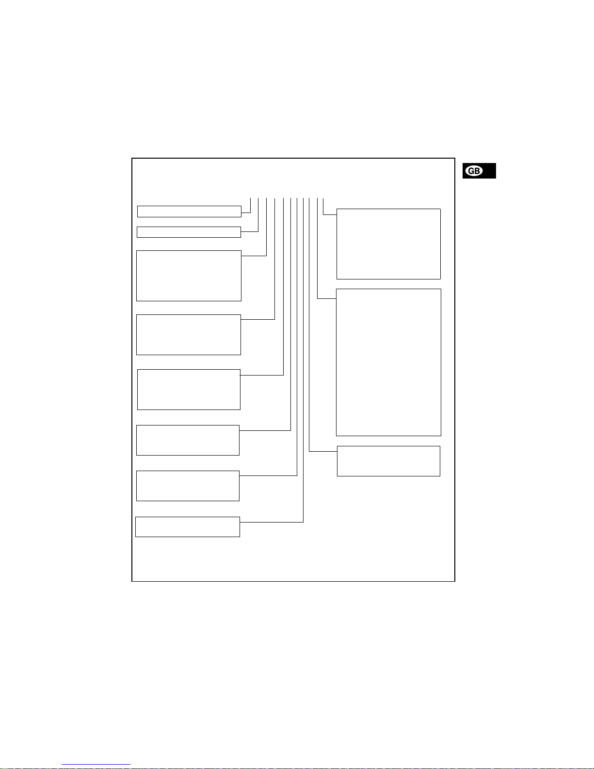
CONTENTS
Page
1. General descr ipti on 4
1.1 Applications 4
1.2 Type key 5
2. Technical data 6
2.1 Mechanical da ta 6
2.2 Electrical data 6
2.3 Input/output d at a 6
2.4 Dimensions 7
3. Installation 7
3.1 Safety instructions 7
3.2 Installation envi r on m en t 7
3.3 Installation of p um p 7
3.4 Installation example 8
3.5 Electrical connection 8
3.6 Connection overview 9
4. Functions 10
4.1 Control panel 10
4.2 Start/sto p of pump 11
4.3 Priming/ventin g of pum p 11
4.4 Level control 11
4.5 Indicator ligh ts and ala r m outp ut 11
4.6 Fieldbus communicat ion 12
4.7 Menu 13
4.8 Operating mod e s 14
4.9 Manual 14
4.10 Pulse 14
4.11 Analo g 14
4.12 Timer 16
4.13 Batch 17
4.14 Anti-c avita t io n 17
4.15 Capacit y l imi t at i on 18
4.16 Counte r s 18
4.17 Resett ing 19
4.18 Return 19
4.19 Language 19
4.20 Input se tu p 20
4.21 Measu rin g uni ts 21
4.22 Dosing monitoring 22
4.23 Control panel lock 23
5. Start-up 24
6. Calibration 25
6.1 Direct calibration 26
6.2 Indirect cali bra tio n 27
6.3 Check calibration 28
7. Maintenan ce 28
8. Service 28
9. Fault finding chart 29
10. Disposal 29
Before beginning in stallation proc ed ur es,
these installation an d opera ting instr uctions should be studie d caref ull y. The installation and opera tio n shou ld also be in
accordance with local regulations and accepted codes of go od p rac ti ce.
1. General description
The GRUNDFOS DME dosing pump is a self-priming
diaphragm pump.
The pump c on sis t s o f:
•a cabinet incorporating the drive unit and elec-
tronics,
•a dosing head with back plate, diaphr ag m,
valves, connections and vent valve and
•a control panel incorporating display and but tons.
The control panel can be fitted either to the end or
to the side of the cabinet.
Being equipped with a stepper motor, this dosing
pump is unique in its field. The stepper motor offers
the possibility of varying the capacity by changing
the duration of the dosing stroke.
Furthermore, the mot or is co nt rolled in s uch a wa y
that the dosing gets as even and constant as possible, irrespective of the capacity range in which the
pump is oper a ting.
This is carried out as follows:
The speed of the suction stroke is kept constant and
the stroke relatively short, irrespective of the capacity. Contra ry to con v en tional pump s, whic h gener ate
the dosing st ro ke as a short pu l se, th e du ration of
the dosing stroke will be a s lo ng a s po ssible. Th us,
an even dosing without peak values is ensured. As
the pump is always dosing at full stroke length, it ensures the same high accuracy and suction capability,
irrespective of the capacity, which is infinitely variable in the ratio of 1:1000 .
The pump features an LCD display and a userfriendly control panel whi ch giv es acce ss to the
pump functions .
1.1 Applications
The DME dosin g pu m p is designed f or h an dl in g
chemicals within the following ranges of applications,
among others:
• Drinking water treatment.
• Wastewater treatment.
• Swimming pool water treatment.
• Boiler water treatment.
• Cooling wate r tr ea tm en t.
• Proc ess wate r tr ea tm en t.
• Washing sy ste ms.
Page 4
5
1.2 Type key
(Cannot be u sed f or p um p co nf i gu ra tio n. )
Example
:
Pump range DME ..
Control variant Code
Standard A
Standard + alarm relay AR
Standard + Profibus AP
Standard + GENIbus AG
Dosing head ma t eria l Code
Polypropylene PP
PVDF PV
Stainless steel 1.4401 SS
Code Mains plug
F EU (Schuko)
B USA, CAN
GUK
IAU
ECH
JJP
Code
Connection,
suction/disch arge
1 Tubing 6/9
Tubing 4/6
supplied with the pump
2 Tubing 6/9
Tubing 6/12+9/12
supplied with the pump
3 Tubing 4/6
4 Tubing 6/9
5 Tubing 6/12
6 Tubing 9/12
A Threaded Rp 1/4
B Threaded Rp 3/8
E Cementing d. 10
F Cemen ting d. 12
Code Valves
1 Standard valve
2 Spring-loaded valve
Valve ball material Code
Ceramics C
Stainless ste el 1. 44 01 SS
Gasket material Code
EPDM E
FKM V
PTFE T
Maximum pres sur e [b ar]
Control panel Code
Front-fitted F
Side-fitted S
Voltage Code
1 x 100-240 V, 50-60 Hz 3
DME 2-18 A-PP/E/C-F-3 1 1E F
Page 5
6
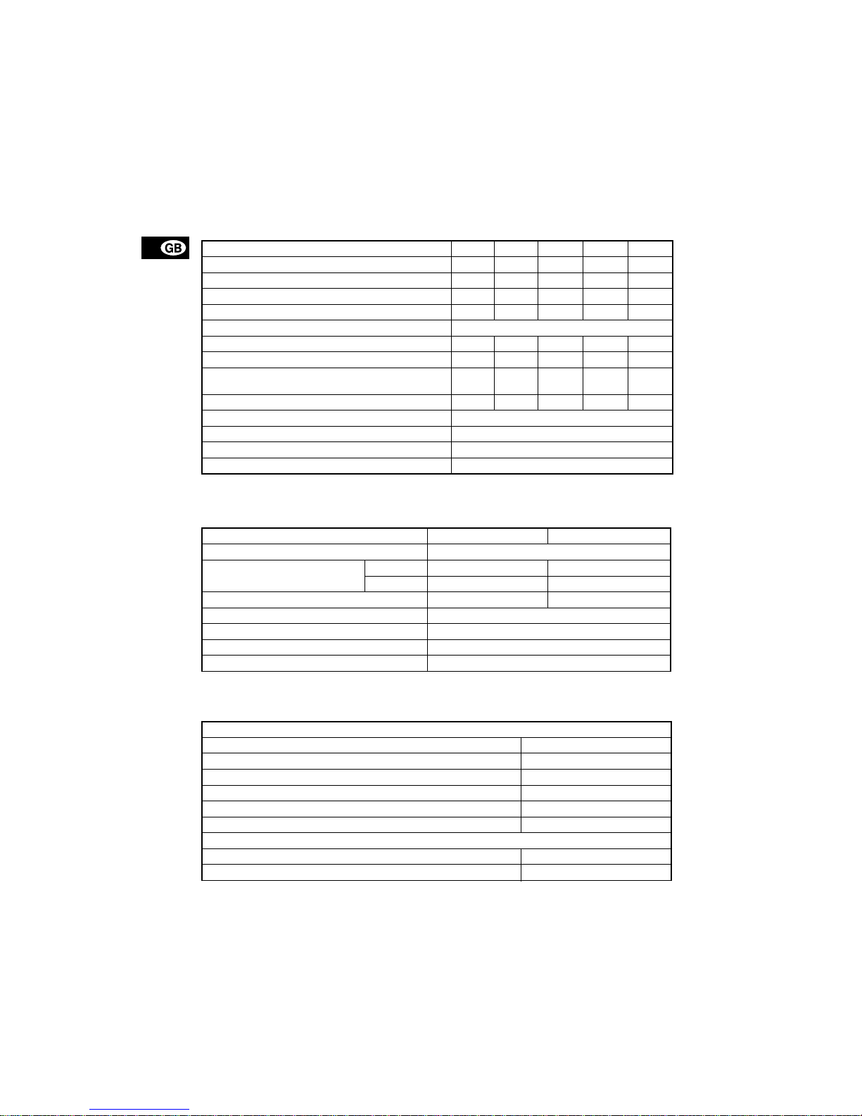
2. Technical data
2.1 Mechanical data
*1 Irrespective of counter pressure
*
2
Maximum suction lift 1 metre
2.2 Electrical data
2.3 Input/output data
The pump offers vario us in put a n d o u tput po ssib ilities, depending on contro l var iant.
DME 2 DME 8 DME 12 DME 19 DME 48
Maximum capa city without anti- cavi ta tio n *
1
[l/h] 2.5 7.5 12 18.5 4 8
Maximum capacity with anti-cavitation *
1
[l/h] 1.8 5.6 9 14.5 37
Maximum pressur e [bar ] 18 10 6 6.2 2.6
Maximum stroke rate per minute [stroke/min.] 180 180 180 151 151
Maximum suctio n l ift during operation [m] 6
Maximum suction lift wh en p r imin g w ith wet valves [m] 1.8 3 3 3 3
Maximum viscosity wi th spr in g -lo ad ed valves *
2
[mPas] 500 500 500 500 100
Maximum viscosity w ithou t spr ing- loade d valves *
2
[mPas]
200 200 200 200 100
Diaphragm diameter [mm] 28 38 42.5 55 77
Liquid tempe rat ur e [°C] 0 to 50
Ambient temperature [°C] 0 to 45
Accuracy of repeatability ±1%
Sound pressure level [dB(A)] <70
DME 2, 8, 12 DME 19, 48
Supply voltage [VAC] 1 x 100-240
Maximum current consumption [A]
at 100 V 0.30 0.36
at 230 V 0.16 0.26
Maximum power co ns um pt i on P
1
[W] 18 22
Frequency [Hz] 50-60
Enclosure class IP 65
Insulation class B
Supply cable 1.5 m H05RN-F with plug
Signal input
Voltage in level sensor input [VDC] 5
Voltage in pulse input [VDC] 5
Minimum pulse-repetition period [ms] 3.3
Impedance in analog 4-20 mA input [Ω]250
Maximum loop resistan ce in p uls e s ign a l cir cu it [ Ω ]350
Maximum loop resistan ce in level signal circuit [Ω]350
Signal ou tput
Maximum load of a larm relay output , a t oh m i c lo ad [ A ] 2
Maximum voltage, al arm relay output [V ] 250
Page 6

7
2.4 Dimensions
See dimensions at the end of these instructions.
All dimensions are in mm.
3. Installation
3.1 Safety in structions
• When wor kin g w ith ch emica ls, lo ca l sa fety r ules
and regulations must be observed (e.g. wear protective clothes).
• Before starting work on the dosing pump and system, disconnect the electricity supply to the pump,
ensuring that i t ca nn ot be a ccidentally switche d
on. Before reconnecting the ele ctr icity sup ply,
make sure that the dosing hose is positioned in
such a way that any chemical left in the dosing
head is not ej ect ed , the r eby expos ing persons to
danger.
• If the vent valv e in the do sin g head i s used, i t must
be connected to a hose which is led back to the
tank.
• When changing a chemical, make sure that the
materials of the dosing pump and system are resistant to the new c he mic al. If th e re is any r isk of
chemical reaction between the two types of chemicals, clean the pump and system thoroughly before adding the new chemical.
Proceed as follows:
Place the suction tub e in wate r and pr ess the
button until residual chemical has been removed.
Note: When the buttons and are pressed
simultaneously, the pump can be set to run for a
specific number of seconds at maximu m ca pa cit y.
The remaining number of se cond s w ill a ppea r in
the display. The maximum value is 3 00 s eco n ds.
3.2 Installation environment
• Expos ure to dir ect sun lig ht shou ld be avoided.
This applies especially to pu m ps with p la stic d osing heads, as this material can be damaged by
sunlight.
• If the pump is instal le d ou tsi d e, a n en clo su re o r
similar protection is requir ed t o pr otect the pump
against rain and simil ar weath ers.
3.3 Installation of pump
• See also the installation example in section
3.4
.
• Note: The dosing head may contain water from
the factory test. If a liquid which must not come
into contact with wate r is to be d os ed , i t is r eco m mended to le t th e pu mp run with an ot he r l iqu id to
remove the water from the dosing head before installation.
• Always install the pump on the supporting foot
with vertical suction and discharge ports.
• Always use suitable tools for the mounting of plastic parts. Never apply un ne ce ssa ry force.
• Make sure that the dosing pump and system are
designed in such a way that neither system equipment nor buildings are dama ged in ca se of leakage from the pump or rupture of hoses/pipes. The
installation of l e ak ag e ho ses and collectin g ta nk s
is recommended.
• Make sure th at the drain hol e in th e dosing head
points downwards, see fig. 1.
Note: It is important that the drain pipe/ho le is not
inserted dir ec t in to the tank conten ts, as ga sse s
may penetrate into the pump.
Fig. 1
100%
100%
TM01 8420 5099
hole
Drain
Page 7

8
3.4 Installation exam ple
The drawing in fig. 2 shows an installation example.
Fig. 2
3.5 Electrical connection
• The electrical connection of the pump should be
carried out by qualified pers ons in a cco r dance
with local regulations.
• For electrical data of the pump, see section
2.2
.
• Do not lay signal cabl es, if any, together with
power cables.
TM01 8421 1600
The DME pump ca n be installed in ma ny different ways. The sketch below s ho ws an example w ith sidefitted control panel. Th e ta nk is a G RUN DF OS c hemi cal ta nk wit h a G RUN DF OS leve l c on trol un it.
Page 8
9
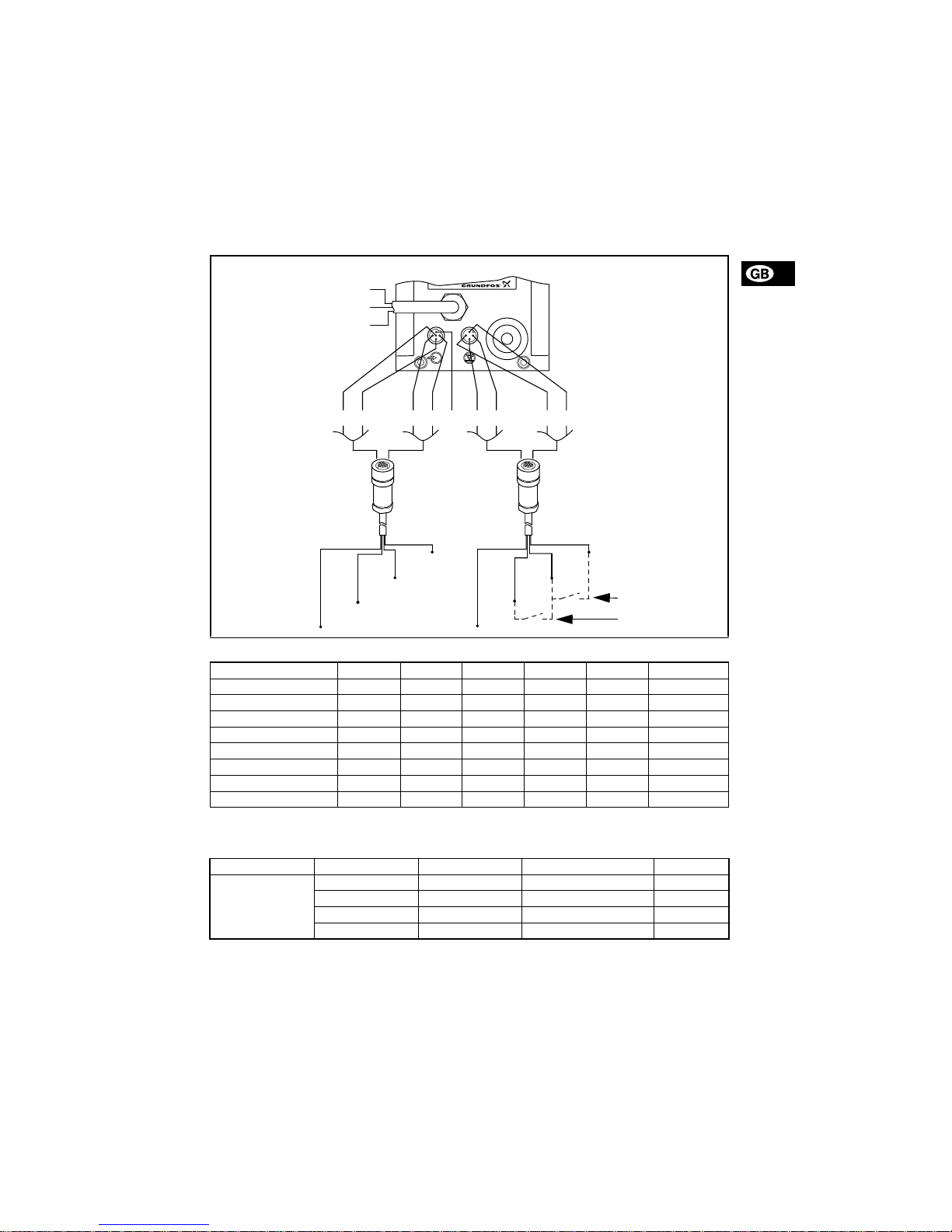
3.6 Connection overview
Fig. 3
Control input:
1 = Contact for pulse signal
2 = Contact for external on/off
Level input:
TM01 8422 0603
2
3
1
4
1
3
4
5
1
3
4
5
3
1
4
2
2
Alarm relay (control variant “AR” only)
Control cable,
see table below
Level cable,
see table below
“NO” black
“NC” blue
“Com” brown
Empty tank
Low level
Number / colour 1 / brown 2 / white 3 / blue 4 / black 5 / grey Description
Function
Manual 2 2
Pulse 1 1
Pulse + external on/o ff 1 1 + 2 2
Analog – + mA signal
Analog + external on/off 2 2 – + mA signal
Timer + external on /off 2 2
Batch 1 1
Number / colour 1 / brown 2 / white 3 / blue 4 / black
Function
Low level Low level
Empty tank Empty tank
Low level Empty ta nk Low level + empty tank
Dosing monitoring Dosing monitoring
Page 9
10
4. Functions
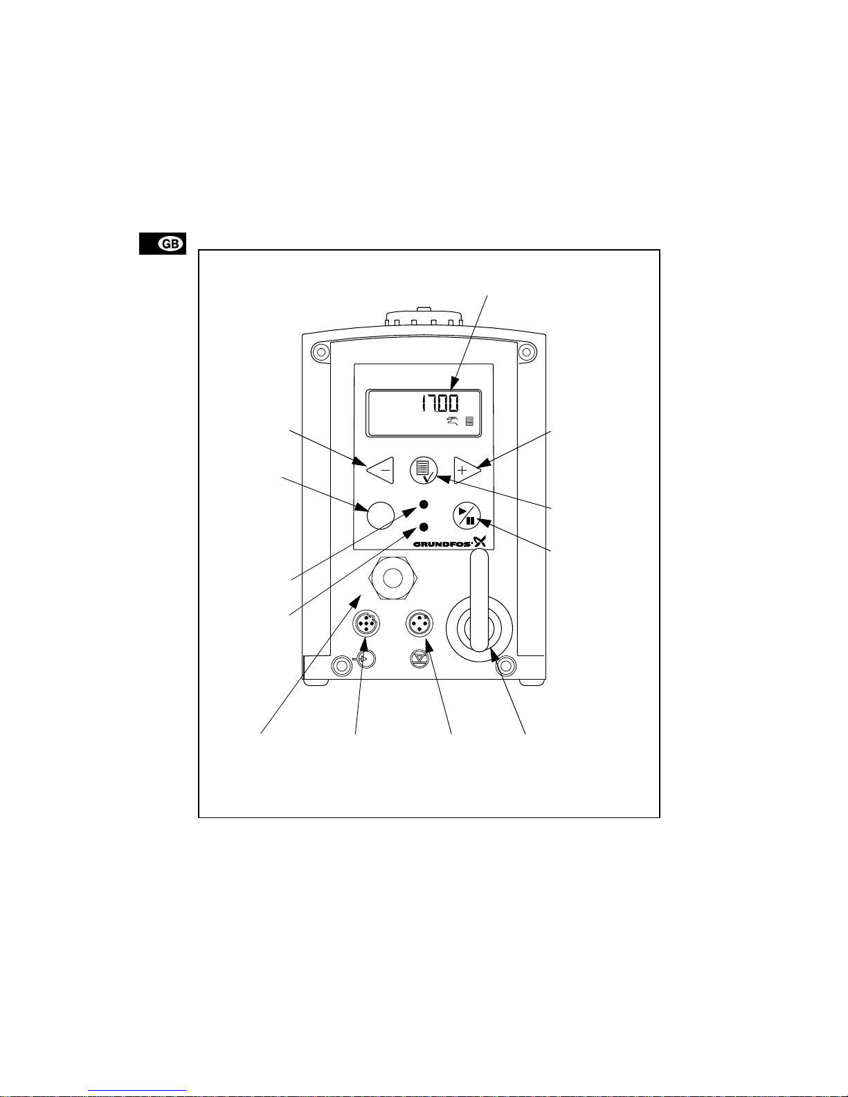
4.1 Control panel
Fig. 4
TM01 8423 0100
ml/h
100%
LCD display,
see section
4.7
Navigation/
settings,
see section
4.7
Menu,
see section
4.7
On/off button,
see section
4.7
Mains connectionM12 connection
level control,
see section
4.4
M12 connection
pulse/analog input,
see section
4.4
Connection
alarm relay/bus.
Control variants
“AR”, “AP” and “ A G” ,
see sections
4.5
and
4.6
Red
indicator light,
see section
4.5
Green
indicator light,
see section
4.5
Maximum capacity
(priming),
see section
4.3
Navigation/
settings,
see section
4.7
Page 10
11
4.2 Start/stop of pump
The pump can be started/stopped in three different
ways:
• Locally on the pump control panel.
• By mean s of an extern al on /off switch con necte d
to the pulse input. See connection overview in
section
3.6
.
• By switching on/ off t he e lectr ic ity su pp ly.
4.3 Priming/venting of pump
The pump control panel incorporates a button.
Press this button if the maximum pump capacity is
required ove r a s ho rt p er iod , e.g. during st ar t- up .
When the button i s rel ea se d, th e pu mp au t oma tic a lly
returns to the previou s oper at ing mod e.
During priming/venting, it is recommended to let the
pump run without a counter pressure or to loosen the
vent valve by giving it a 1/8 to 1/4 turn.
Note: When the butt on s and are pr ess ed si-
multaneously, the pump can be set to run for a specific number of seco nd s a t ma ximu m ca pacity. The
remaining number of seco nds will appear in the dis play. The maximum value is 300 seconds.
4.4 Level control
The pump can be fitted with a level control unit for
monitoring of the chemical level in the tank.
The pump can react to two level signals. The pump
will react differently, depending on the influenc e on
the individual level sensors.
* Control variant “AR” o nl y.
See section
3.6
for connectio n of th e level control
unit and alar m output.
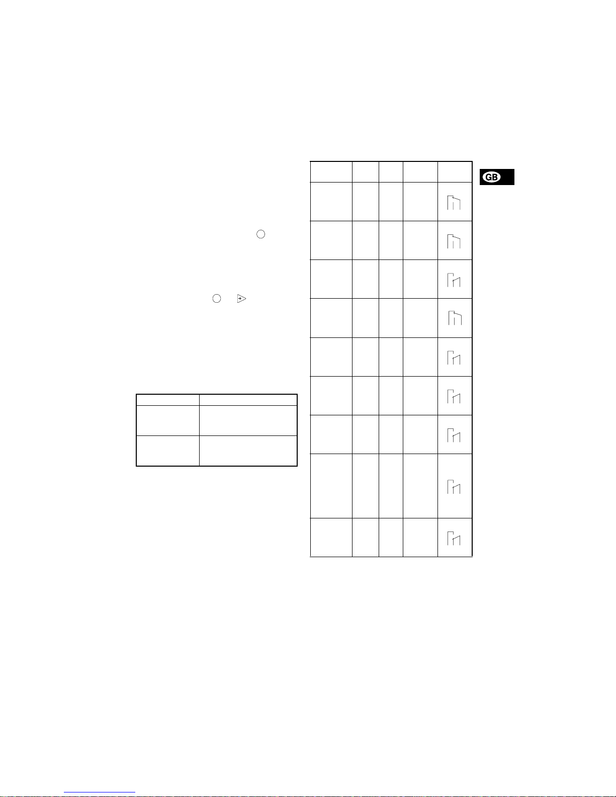
4.5 Indicator lights and alarm output
The green and red indicator lights on the pump are
used for ope rat in g an d fault indicati on .
In control varia nt “A R ”, th e pump can activ at e an external alarm s ign al by mea ns of a b ui lt -i n al arm r el ay.
The alarm signal i s act i vat ed by m eans of an in te rn al
potential-free contact.
The functions of the i ndica tor li ghts and the bu ilt-in
alarm relay appear from th e table belo w:
!1
Control variant AR only.
!2
Requires connection to level sensors.
!3
Requires activation of the dosing monitoring
function and connection to a dosing monitor.
Level sensors Pump reaction
Upper sensor
activated
(closed contact )
• Red indicat or lig h t is o n.
• Pump running.
• Alar m r elay activated.*
Lower sensor
activated
(closed contact )
• Red indicat or lig h t is o n.
• Pump stopped.
• Alar m r elay activated.*
100%
100%
Condition
Green
LED
Red
LED
Display
Alarm
output
!1
Pump
running
On Off
Normal
indication
Set to stop
Flash-
ing
Off
Normal
indication
Pump fault Off On EEPROM
Supply
failure
Off Off Off
Pump running, low
chemical
level
!2
On On
Normal
indication
Empty
tank
!2
Off On
Normal
indication
Analog
signal
< 2 mA
Off On
Normal
indication
The dosed
quantity is
too small
according
to the signal from the
dosing
monitor
!3
On On
Normal
indication
Overheating
Off On
MAX.
TEMP.
132
NC NO C
132
NC NO C
1
23
NC NO C
132
NC NO C
1
23
NC NO C
1
23
NC NO C
1
23
NC NO C
1
23
NC NO C
1
23
NC NO C
Page 11
12
4.6 Fieldbus communication
The pump can be configured for fieldbus applications.
The following b u s t ype s ar e ava i la ble:
Separate instructions are supplied with each bus
type.
Control variant Bus type
AP Profibus
AG GENIbus
Page 12

13
4.7 Menu
The pump features a user-friendly menu which is activated by pressing the button. During start-up, all
texts will appear in English la ngua g e. T o s elect la nguage, see section
4.19
.
All menu items are described in the following sections. When appears at a menu item, it means
that this item is activated. By sele ct ing “ RETURN”
anywhere in the menu structure, you will return to the
operating display without changes.
Fig. 5
See section
4.9
See section
4.23
See section
4.10
See section
4.17
See section
4.11
See section
4.18
See section
4.12
See section
4.19
See section
4.13
See section
4.15
See section
4.14
See section
4.20
See section
6
See section
4.21
See section
4.16
Page 13

14
4.8 Operating modes
Note: The displayed l and ml v alu es ar e on ly re l iab l e
if the pump has been calibrated to the actual installation, see section
6
.
The pump can run in five different operating modes:
•Manual
•Pulse
•Analog
•Timer (internal batch control)
• Batch (external batch control)
See description in the following sections.
4.9 Manual
The pump is dosi ng as constantl y and evenly as possible, without a ny ex te rn al sig na l s.
Set the quanti ty to be dosed in l/h or ml/h. The pump
automatically ch a ng es over betwee n th e me as ur i ng
units.
Setting range:
DME 2: 2.5 ml/h - 2.5 (1.8*) l/h
DME 8: 7.5 ml/h - 7.5 (5.6*) l/h
DME 12: 12 ml/h - 12 (9*) l/h
DME 19: 18.5 ml/h - 18.5 (14.5*) l/h
DME 48: 48 ml/h - 48 (37*) l/h
* The figures in brac kets ind icat e the ma ximum ca-
pacity when the anti-ca vitation fu nction is activated.
Fig. 6
4.10 Pulse
The pump is dosing according to an external pulse
signal, i.e. a water meter with pulse output or a controller.
Set the quantity to be dosed per pulse in ml/pulse.
The pump adjusts its capacity acco rding to two factors:
• Frequency of external pulses.
• The set quantity per pulse.
Setting range:
DME 2: 0.000018 m l/pulse - 5 ml/pulse
DME 8: 0.000069 m l/pulse - 15 ml/pulse
DME 12: 0.000111 ml/puls e - 24 ml/pulse
DME 19: 0.000204 ml/puls e - 37 ml/pulse
DME 48: 0.0053 0 ml/pulse - 96 ml/pulse
Fig. 7
If the set qu an tit y p e r p u lse mu l ti pl ie d by the pulse
frequency exceeds the pump capacity, the pump will
run at maximum capacity. Exc es s p uls es will be ig nored and the “actual capacity” display will flash.
4.11 Analog
The pump is d osin g according to a n ex te rn al an alog
signal. The dosed quantity is proportional to the input
value in mA.
4-20 (default): 4 mA = 0%.
20 mA = 100%.
20-4: 4 mA = 100%.
20 mA = 0%.
0-20: 0 mA = 0%.
20 mA = 100%.
20-0: 0 mA = 100%.
20 mA = 0%.
See fig. 8.
The capacity limitatio n will i nfl uenc e t he capacity.
100% corresponds to the maximum capacity of the
pump or the set m aximu m ca pa city , s ee se ct ion
4.15
.
Fig. 8
Set valu e
TM02 4498 1102
Set quantity in
ml/pulse
Actual capacity
in ml/h or l/h
0 4 8 12 16 20
0
20
40
60
80
100
4-20 mA
0-20 mA
[mA]
[%]
Page 14

15
Fig. 9
If 4-20 mA or 20-4 mA is selected and the signal falls
below 2 mA, the pump will indicate a fault. This situation occurs if the connection is interrupted, for instance if the wire is damaged.
Change the analog mo de as illu st ra te d in fig . 1 0:
Fig. 10
Value
according to
analog signal
Use the buttons
for navigation
Page 15
16
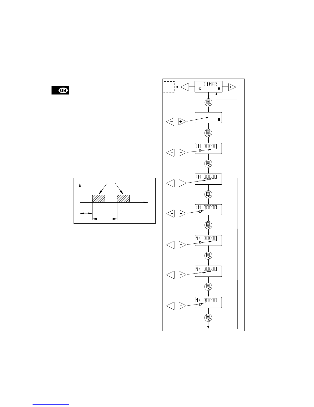
4.12 Timer
The pump is dosing th e s et quan ti t y in bat che s a t t he
maximum capacity or the set maximum capacity, see
section
4.15
.
The time until the first dosing “NX” and the following
sequences “IN” c an b e set in m i nu te s, ho u rs an d
days. The maxim um t i me li mi t is 9 days, 23 ho ur s
and 59 minut es (9 :2 3: 59 ). T he l o we st acceptable
value is 1 minute.
The interna l time r cont inues even
if the pump is stopped by means of the on/off button,
empty tank or stop signal , see fig . 11.
During operation, “NX” will alwa ys cou n t dow n fro m
“IN” to zero. In th is way, the remaining tim e un til th e
next batch can a l wa ys be r ea d.
“IN” must be higher than the time required to perform
one batch. If “IN” is low er, t he n ext b at ch will be ig nored.
In case of supply fa ilu re , the s et qu a nti ty to be
dosed, the “IN” time and the remaining “NX” time are
stored. When the sup ply is re conn ecte d, the pu mp
will start up with the “NX” time at the time of the supply failure. In this way , t he ti me r cyc le will c ontin ue ,
but it has been delayed by the duration of the supply
failure.
Fig. 11
Setting range:
DME 2: 0.23 ml/batch - 5 l/batch
DME 8: 0.69 ml/batch - 15 l/batch
DME 12: 1.11 ml/batch - 24 l/batch
DME 19: 2.04 ml/batch - 37 l/batch
DME 48: 5.3 ml/batch - 96 l/batch
Only values corresponding to complete dosing
strokes (accordi ng to t he ca lib ra tio n fa ctor) ca n be
selected.
Example: If the calibration factor is 23.3 (= 0.233 ml/
stroke), the minim um se tta bl e val ue in time r or batch
mode will be 0.233 ml -> the n ext will be 0 .4 66 ml ->
the next will be 0.699 ml, etc.
These steps wi ll continue up to a value correspond ing to 100 dosing strokes. Abov e this val ue, the set ting range has standard steps as in other operating
modes.
If the calibration f ac tor is changed after se ttin g of
timer or batch mode , the p ump will automatically recalculate a new amount of dosing strokes per batch
and change the dis pl a y val ue to t he ne ar est pos s ibl e
value compared to the first one set.
Fig. 12
TM01 8942 0900
NX
IN
Quantity per bat ch
Set quantity
per batch
Set IN value
in minutes
Set IN value
in hours
Set IN value
in days
Set NX value
in hours
Set NX value
in minutes
Set NX value
in days
Page 16

17
4.13 Batch
The pump is dosi ng th e s et qua nt it y in bat c he s a t the
maximum capacity or the set maximum capacity, see
section
4.15
.
The quantity is dosed every time the pump receives
an external pulse.
If the pump receives new pulses before the previous
batch is performed, these pulses will be ignored.
Fig. 13
The setting range is the same as for Timer, see section
4.12
.
Fig. 14
4.14 Anti-cavitation
The pump features an anti-cavitation function. When
this function is selected, the pump extends and
smooths its suct ion stroke, resulting i n s of te r pr iming.
The anti-cavitation function is used:
• when pu mp in g liquids of high viscosity,
• in the case of a long suction tube and
• in the case of a high suction lift.
The maximum pump capacity is reduced when this
function is selected. See section
2.1 Mechanical
data
.
Fig. 15
TM01 8947 0900
Pulse Pulse
Quantity per bat ch
Set value
per batch
Operating display
Page 17
18
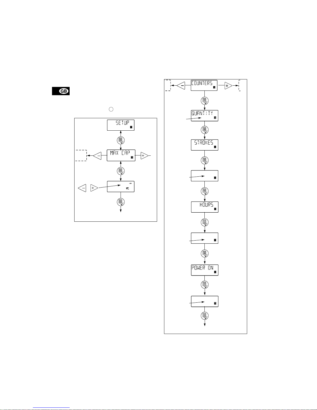
4.15 Capacity limitat ion
This function offers the p ossib ility of r ed uci ng t he
maximum pump capac ity (MAX CAP). It influen ces
the function s in whic h the pu mp is nor mally oper ating
at maximum capacity.
Under normal operating conditions, the pump cannot
operate at a capacity which is higher than the one
stated in the display. This does not apply to the maximum capacity button , see section
4.3
.
Fig. 16
4.16 Counters
The pump can display “non-resettable” counters for:
•“QUANTITY”
Accumulated value of dosed quantity in litres or
US gallons.
•“STROKES”
Accumulated number of dosing strokes.
•“HOURS”
Accumulated number of operating hours
(Power on).
•“POWER ON”
Accumulated number of times the electricity supply has been switc he d on .
Fig. 17
100%
Set maximum
capacity
Operating display
Operating display
Total number
of strokes
Total number
of operating
hours
Total number
of starts
Total dosed
quantity
Page 18
19
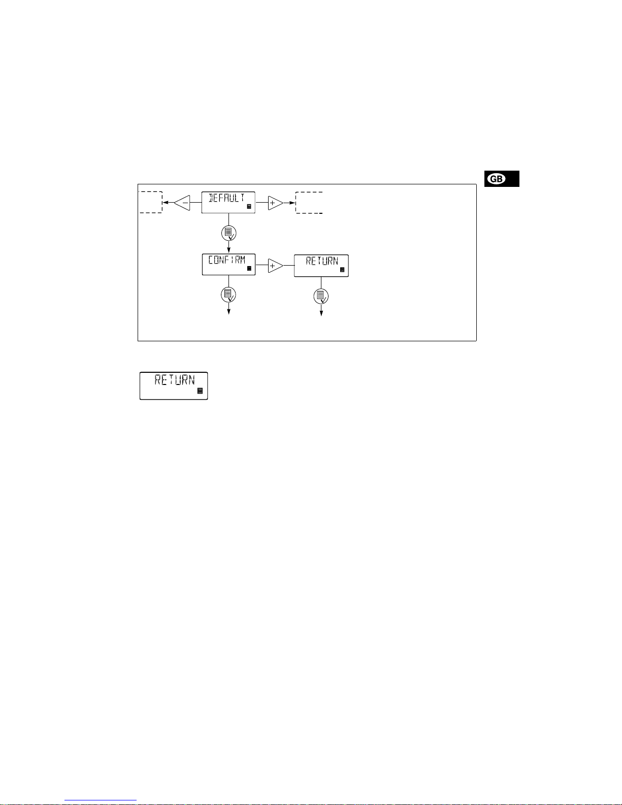
4.17 Resetting
When “DEFAULT” is activate d, th e pum p will r etur n
to the factory settings.
Note: The calibration is also set b ac k t o th e d e fau lt
setting. This means that a new calibration is required
when the “DEFAULT” function has been used.
Fig. 18
4.18 Return
Fig. 19
The “RETURN” function m ake s it p o ssible to r etur n
from any level in the menu to the operating display
without changes after the menu functions have been
used.
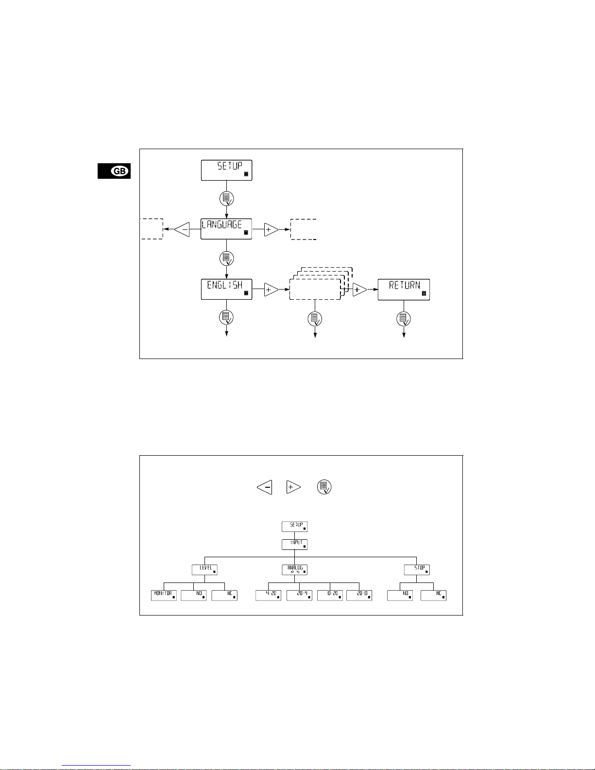
4.19 Language
The display text can be displayed in one of the following languages:
•English
•German
•French
• Italian
• Spanish
• Portugu es e
•Dutch
•Swedish
•Finnish
•Danish
•Czech
• Slovak
• Polish
• Russian
Operating display Operating display
without changes
Page 19
20
Fig. 20
4.20 Input setup
Fig. 21 shows all possible settings.
The level and st op i n pu ts ca n be ch an ge d fr om N O
(normally open) t o N C (no rm a lly clos ed ) fu nction. If
changed, the i n pu ts mu st be s ho rt -circuited in no r mal operation.
For the analog input, one of the following signal
types can be selected:
• 4-2 0 mA (defa ult),
• 20- 4 mA,
• 0-2 0 mA,
• 20- 0 mA.
See also section
4.11 Analog
.
Change the level input to an input for dosing monitoring as illustrated i n fig. 2 1.
Fig. 21
Operating display Operating display Operating display
without changes
Use the buttons
for navigation
Page 20
21
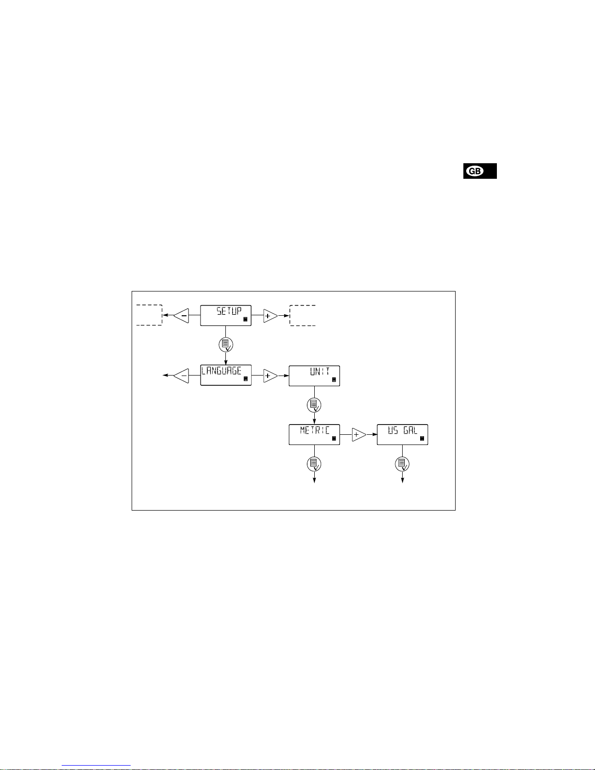
4.21 Measuring units
It is possible to s elect m etr ic units (l itr e/m illi litr e) o r
US units (gallons/millilitre).
Metric measuring units:
• In manual and analog modes, set the quantity to
be dosed in litres per h our ( l/h ) or millilit re s p er
hour (ml/h).
• In pulse mode, set the qu an ti t y t o be dosed in
ml/pulse. The actual capacity is indicate d in litres
per hour (l/h) or millilitres per hour (ml /h).
• For calibration, set the quantity to be dosed in
ml per 100 strokes.
• In timer and batch modes, set the quantity to be
dosed in litres (l) or millilitres (ml).
• Under th e “ QUANTITY ” me nu ite m in th e
“COUNTERS” me nu, the dosed qu an ti t y i s in di cated in litres.
US measuring units:
• In manual and analog modes, set the quantity to
be dosed in gallons per ho ur (gp h).
• In pulse mode, set the quantity to be do se d in
ml/pulse. The actual capacity is indicated in
gallons per hour (gph).
• For calibration, set the quan tity to b e do se d in
ml per 100 strokes.
• In timer and batch modes, set the quantity to be
dosed in gallons (gal).
• Under th e “QUANTI TY” m e nu item in the
“COUNTERS” menu, the dosed quantity is indicated in US gallons (gal).
Fig. 22
Operating display Operating display
3 x
Page 21

22
4.22 Dosing monitoring
A dosing monitor is available as an accessory . Separate instructions are su pp lie d with t he m oni tor.
Fig. 23
The dosing moni tor is desig ned t o moni tor the dos ing
of liquids whi c h ma y cau se g as accumulation in the
dosing head, thus stopping the dosing process even
if the pump is still ope ratin g.
For every meas ur ed d osing stroke, t he d os ing m on i tor gives a pulse signal to the level input so that the
pump can compare performed dosing strokes (from
internal stroke sensor) with externally measured
physical strokes (from the dosing monitor). If an external dosing str o ke is n o t m e asu re d to ge th er wi th
the internal dos ing stroke, this is co ns ide re d a fa ult
that may have been provoked by empty tank or gas
in the dosing head.
TM02 2029 3201
Monitor mounted on the suction side of the pump
Dosing stroke measu re d
Page 22

23
4.23 Control panel lock
It is possible to l o ck t he b ut ton s on th e con tr ol pa ne l
to prevent malfunction of the pump. The locking
function can be set to “ON” or “OFF”. The default
setting is “OFF”.
A PIN code must be entered to change from “OFF” to
“ON”. When “ON” is selected for the first tim e,
“_ _ _ _” will appear in t he d isp lay. I f a co d e ha s a lready been entered, it will a ppe ar wh en a n atte mp t
to change to “O N” is ma d e. T his co de ca n ei the r be
re-entered or changed.
If no code has been entered, a code must be set in
the same way as the “NX” and “IN” values desc rib ed
in section
4.12
.
If a code has already been entered, active digits are
flashing.
If attempts are made to operate the pump in locked
condition, “LOCKED” will app ear in the disp la y for
2 seconds, followed by “_ _ _ _”. A code must be entered. If the entering of a code has not been started
within 10 seconds, the operating display without
changes will appear.
If a wrong code is entered, “L OCKED ” will a p pear in
the display for 2 seconds, followed by “_ _ _ _”. A
new code must be entered. If the entering of a code
has not been started within 10 seconds, the operating display without changes will appear. This display
will also appear if the entering of the correct code exceeds 2 minutes.
If the locking function has been activated but the
control panel is unlocke d , the co ntro l pan e l will be
locked autom at ica ll y i f i t is no t op er at ed f or 2 m i nutes.
The locking f un c t ion ca n al s o be r ea cti v at ed b y s electing “ON” in the “LOCK” menu. The previously entered code will then appear and must be re-entere d
by pressing the button four times. The code can
also be change d.
The control panel can be unlocked either by means
of the selected co de o r th e fa cto ry co de 2 58 3.
The following buttons and inputs are still active when
the panel is locked:
• Prim i ng ( -button).
• On/of f but to n.
• All externa l i np ut s.
Fig. 24
Activating the locking function and locking the
control panel:
1. Select “LOCK” in the menu.
2. Select “ON” by means of the buttons and
and confirm with .
3. Enter or re-ent er a co d e by me an s o f th e buttons
, and .
The locking functi o n ha s no w been act iv at ed and th e
control panel is locked.
Unlocking the co ntrol panel ( with out deac tiva ting
the locking function):
1. Press once. “LOCKED” appears in the display
for 2 seconds, followed by “_ _ _ _”.
2. Enter the code by means of the buttons ,
and *.
The control panel has now been unlocked and will
automatically be locked again if the control panel is
not operated f or 2 m i nu te s.
Deactivating the locking function:
1. Unlock the control panel as described above.
2. S e lect “ LO CK ” in th e me nu.
3. Select “OFF” by mean s of t he b u tton s and
and confirm with .
The locking function has now been deactivated and
the control panel is unlo cke d.
* The panel can always be unlocked with code 2583.
100%
Operating disp lay
Operating display
Page 23
24
5. Start-up
If the pump is n ot operating sat isf act or i ly, se e se cti o n
9. Fault finding char t
.
Step Action
1
Connect the hoses/pipes:
• Connect the suction and dosing tubes/pipes to the pump.
• Connect a tube to the vent valve, if required, and lead the hose to the
tank.
2
Switch on the electricity supply:
• The di splay is o n.
• The gree n indi cato r light i s flashi ng (t he pum p has sto pped ).
• Select language, if required, see section
4.19
.
3
Select the operating mode (see section
4.8
):
• Manual .
•Pulse.
•Analog.
•Timer.
•Batch.
4
Connect the cables:
• Connect the control/level cables, if any, to the pump, see section
3.6
.
5
Start the pump:
• Start the pump by p re ssin g th e on /o ff butto n.
• The gree n indi cato r ligh t is per ma nent ly on .
6
Priming/venting:
• Press the button on the pump control panel and let the pump run
without a counter pr essu re. Loose n the vent valve by giving it a 1/ 8 to
1/4 turn, if required.
When the buttons and are pressed simultaneously during priming, the pump can be set to run for a specific number of seconds at
maximum capacity.
7
Calibration:
• When the pump has been primed and is running at the right counter
pressure, calibrate th e pu m p, see se ctio n
6
.
100%
100%
100%
100%
100%
Page 24

25
6. Calibration
It is important that th e p um p is ca lib rate d a ft er in sta llation to ensure that the correct value (ml/h or l/h)
appears in the display.
The calibration can be carried out in three different
ways:
• Dire ct c alibration (recommended).
The dosed quan tity of 100 strokes i s me as ur ed directly. See section
6.1
.
• Ind irec t ca libration.
A calibration factor selected from a table is used
for the specific installa tio n. Thi s m et hod ca n be
used if it is not pos sible to ca rry o u t a d irect ca libration. Indirect calib rati on will ne ve r be a s a ccu rate as direct ca lib ra tio n. Se e sec tio n
6.2
.
• Check ca libr atio n. See section
6.3
.
Page 25
26
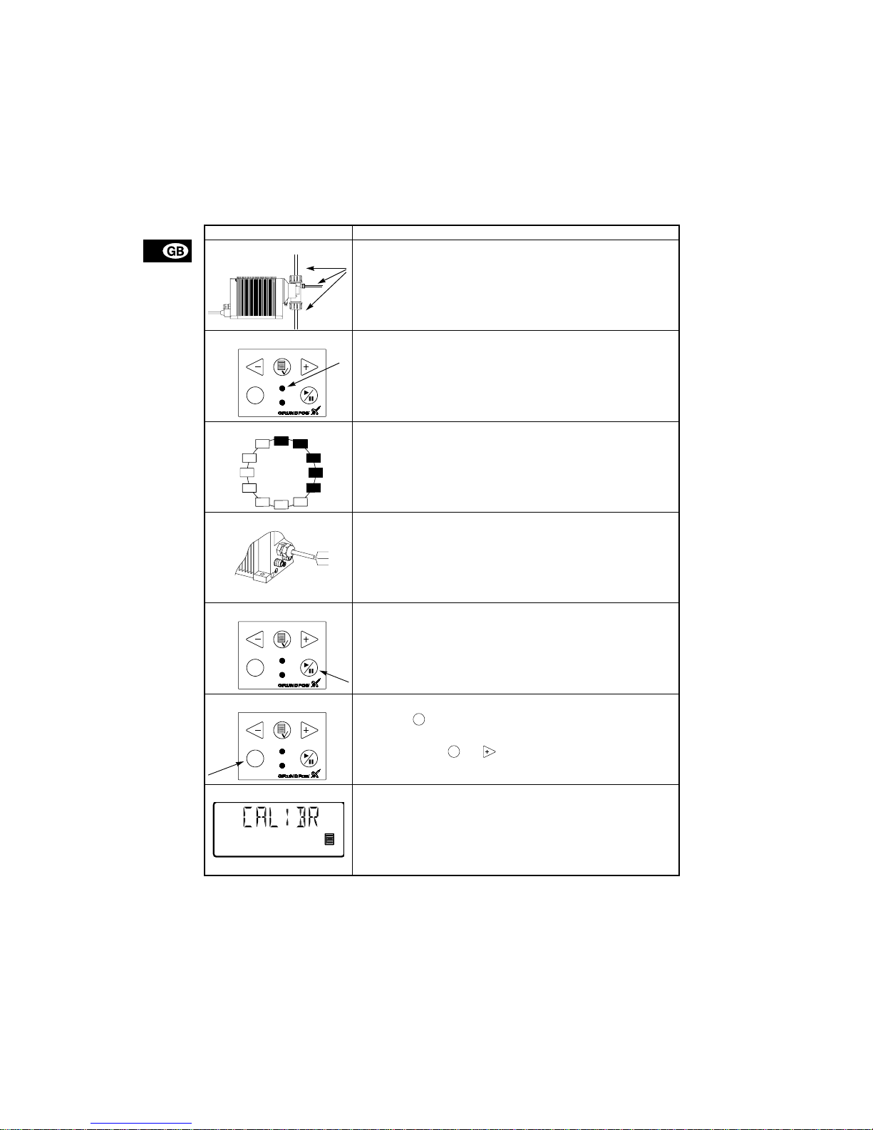
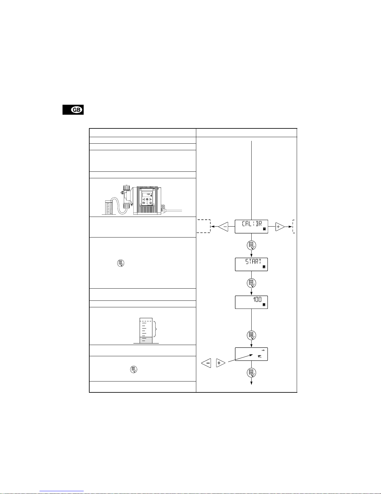
6.1 Direct calibratio n
Before calibration, ma ke sur e :
• that the pum p is in sta lle d with foot valve, injection
valve, etc. in the existing system.
• that the pump is running at the coun te r pre s su re it
is supposed to operate at (adjust the counter pressure valve, if required).
• that the pump is operating with the correct suction
lift.
To carry out a direct calibration, proceed as follows:
Action Pump display
1. Prime the dosing hea d and th e suctio n tubi ng.
2. Stop the pump. The gr ee n LE D i s fl a shin g.
3. F ill a graduated glass with dos ing liquid, Q
1
.
DME 2: approx. 40 ml DME 19: approx. 500 ml
DME 8: approx. 150 ml DME 48: approx. 1000 ml
DME 12: approx. 250 ml
4. Read and note the quantit y Q
1
.
5. Place the suction tu bi ng i n th e grad ua te d gl a ss .
6. Go to the calibration menu, see secti on
4.7
.
7. Press the button twice.
8. The pump is performing 100 dosing strokes.
9. The factory-calibrat i on value a pp ea rs in the display.
10.Remove the suction tubing from the graduated
glass and read Q
2
.
11.Set the display value to Q
d
= Q1 – Q2.
12.C on firm with th e button.
13.Th e pump is now cali bra te d an d re tu rns to the op erating display.
Set value
to Q
d
Operating display
Q
1
Q
2
Q
d
Page 26

27
6.2 Indirect cal i bration
A value from th e following table is to be added to the
default factory cal ibrat ion value in th e displ ay. To reset the pump to the factory calibration value, activate
the “DEFAULT” fu nctio n, see sec tio n
4.17
.
To use the values, the fo llo wing m u st be fu lfi lled :
• The viscosity and density of th e liquid to be dosed
must not differ considerably from water at 20°C.
• A GRUNDFOS installat ion k it o r co rres pond ing
foot valve, in jection valve and hose diameter must
be used.
• The length of the dosing hose must not exceed
6 metres.
• The suction lift must lie between 0.1 and 1.5 metres.
Adding the value:
Fig. 25
Pump type
Values to be added to the calibration value at various counter pressures [bar]
0-1 1-2 2-3 3-4 4-5 5-6 6-8 8-10 10- 12 12-14 14-16 16-18
DME 2 1.4 1.1 0.8 0.5 0.2 -0.2 -0.6 -1.2 -1.8 -2 .4 - 3. 0 -3 .6
DME 8 3.5 2.7 2.0 1.2 0.4 -0.4 -1.6 -3.1 - - - DME 12 2.1 1.3 0.4 -0.4 -1.3 -2.1 -3.4 - - - - DME 19 18.3 12.2 6.1 0 -6 .1 -12.2 -21.4 - - - - DME 48 24.38.3-8.3---------
Operating display
without changes
Operating display
Set value
to table value
+ display value
Page 27

28
6.3 Check calibration
In check calibration, the c alibra tio n value is ca lculated by reading the consumption of chemical in a
specific perio d and co mpar ing this with the number
of dosing strokes performed in the same period.
This calibration method is very accurate and especially suitable for check calibration after long periods
of operation or if d i re ct c ali b rat i on is i m po ssible. Th e
calibration can for instance be carried out when the
chemical tank is replac ed o r fille d.
To carry out a check calibration, proceed as follows:
1. Stop the pump by pr es sin g the button.
2. Read the counter and note the number of dosing
strokes, see s e ction
4.16
.
3. Read and note the quantity in t he ch e mical tank.
4. Start the pump by pressing the button and let
it run for at least 1 hour. The longer the pump is
operating, the more accurate the calibration will
be.
5. Stop the pump by pr es sin g the button.
6. Read the counter and note the number of dosing
strokes, see s e ction
4.16
.
7. Read and note the quantity in t he ch e mical tank.
8. Calculate the dose d quantity in m l a nd t he
number of dosing strokes pe rfor med du rin g the
operating period.
9. C alcula te the calibration value as follows:
(dosed quantity in ml/dosin g s t rokes) x 100.
10.Se t the cal cul ate d value in the calib ration menu
like for indirect calibration, see se ct ion
6.2
.
7. Maintenance
The pump is maintenance-free. However, it is recommended to kee p th e p ump clean.
The dosing pump is produced according to the highest quality standards and has long life. The pump incorporates wear part s such as di aphra gm, v alve s eat
and valve balls.
To ensure long life and to reduce the risk of disturbance of operation, visual checks should be carried
out regularly.
It is possible to order dosing heads, valves and diaphragms in ma te ri a ls which are suit ab le fo r the specific liquid to be pumped. See the product numbers
at the end of these instructions.
8. Service
Before returnin g th e pu m p t o GRU NDF OS fo r s er vice, the safety declaration at the end of these instructions must be filled in b y a u thor ize d pe rso nne l a nd
attached to the pump in a visible position.
Note: If a pump has been used for a liquid which is
injurious to health o r to xic, th e pu m p will be cla ssified as contaminated.
If GRUNDFOS is requested to service the pump, it
must be ensured that the pump is free from substances that can be injurious to health or toxic. If the
pump has been used for such substances, the pump
must be cleaned before it is returned.
If proper cleaning is not p ossib le, all r ele vant infor mation about the chemical must be provided.
If the above is not fu lfille d, G RUNDFO S ca n re fu se
to accept the pump for service. Possible costs of returning the pump are paid by the customer.
The safety declaration can be found at the end of these
instructions (only in English).
Note: The replacement of the supply cable must be
carried out by an authorised GRUNDFOS service
workshop.
Page 28
29
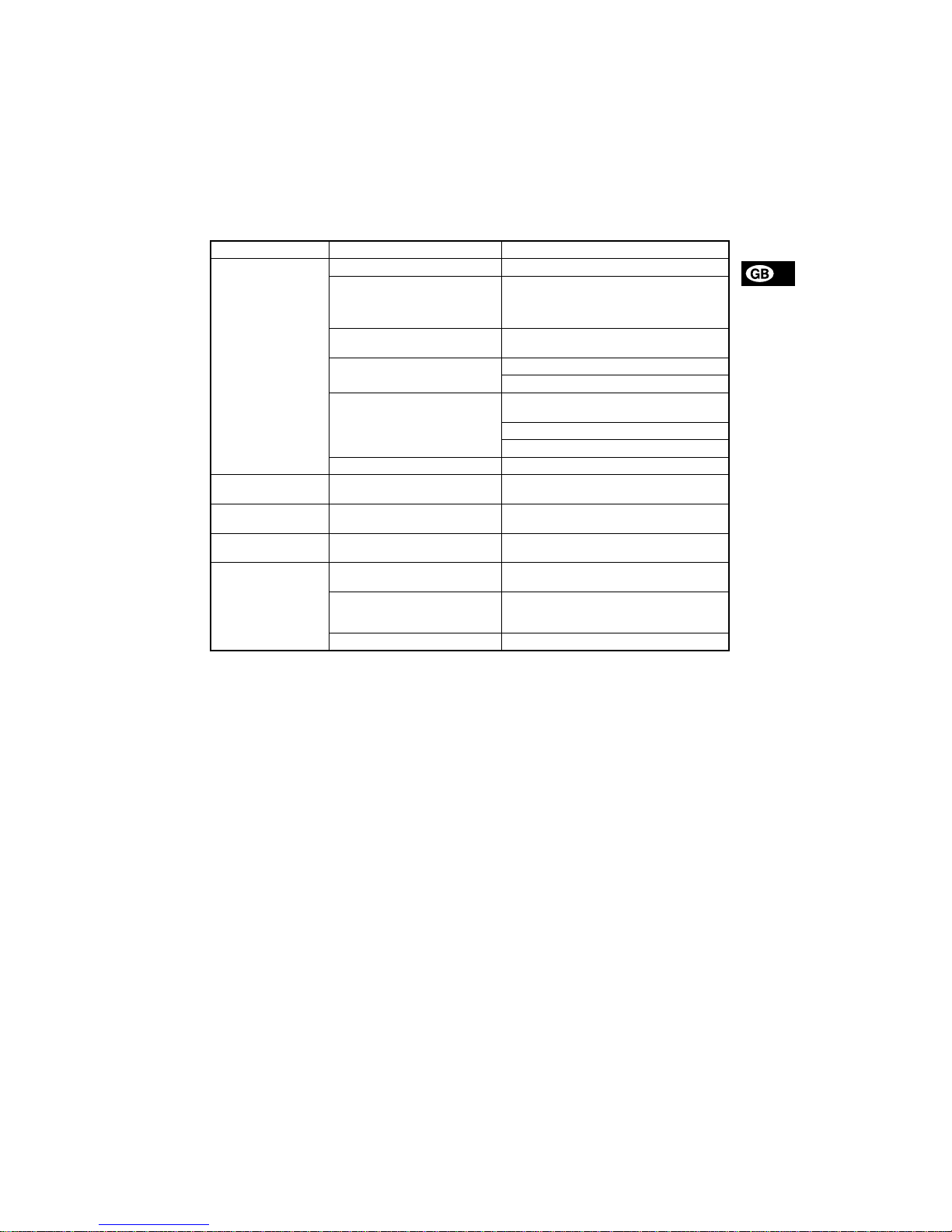
9. Fault finding chart
10. Disposal
Disposal of this product or parts of it must be carried
out according to the f ollowin g guide lin es:
1. Use the local pu blic or p r i vate wast e col l ect i on
service.
2. In case such waste collection ser vice do es not
exist or cannot handle the materials used in the
product, please deliver the product or any hazardous materi als fr om it to you r near es t G RUNDFOS company or service workshop.
Fault Cause Reme dy
The dosing has
stopped or the output
is too low.
Valves leaking or blocked. Check and clean valves.
Valves incorrectly installed. Remove and fit valves. Check that the arrow
on the valve casing is point ing in t he liq uid
flow direction. Check that all O-rings have
been fitted co rr ec tly.
Suction valve or suction pipe/hose
leaking or blocked.
Clean and seal th e su ctio n pipe/hose.
Suction lift too high. Install the pump in a lower position.
Install a priming tank.
Viscosity too high. Select the anti-cavitation function, see sec-
tion
4.14
.
Install a pipe/hose with larger cross-section.
Fit spring-loa ded valves.
Pump out of calibration. Ca librate the pu mp, see sec tio n
6
.
Pump dosing too little
or too much.
Pump out of calibration. Ca librate the pu mp, see sec tio n
6
.
Pump dosing irregularly.
Valves leaking or blocked. Check and clean the valves.
Leakage from drain
hole.
Diaphragm defective. Install a new diaphragm.
Frequent diaphragm
failures.
Diaphragm not fastened properly. Install a new diaphragm and ensure that the
diaphragm is fastened properly.
Counter-pressure too high (measured at the pump discharge port).
Check the system. Check the injection valve,
if required. Redu ce t he dosi ng s trok e b y f itti ng
a pulsation damp ene r.
Sediment in dosing head. Clean/flush the dosing head.
Subject to alteratio ns.
 Loading...