

Page 1

SMART Digital S
DIGITAL DOSING up to 30 l/h
DDA, DDC, DDE
Pumps and accessories
GRUNDFOS DATA BOOKLET
Page 2

SMART Digital S
Table of contents
1. General data 3
Performance range . . . . . . . . . . . . . . . . . . . . . . . . . . . . . . . . . . . . . . . . . . . . . . . . . . . . . . . . . . . . . . . . . . . . . . . . . . . . 3
Features at a glance . . . . . . . . . . . . . . . . . . . . . . . . . . . . . . . . . . . . . . . . . . . . . . . . . . . . . . . . . . . . . . . . . . . . . . . . . . . 4
2. Identification 6
Type key . . . . . . . . . . . . . . . . . . . . . . . . . . . . . . . . . . . . . . . . . . . . . . . . . . . . . . . . . . . . . . . . . . . . . . . . . . . . . . . . . . . . 6
3. Functions 7
Overview of functions. . . . . . . . . . . . . . . . . . . . . . . . . . . . . . . . . . . . . . . . . . . . . . . . . . . . . . . . . . . . . . . . . . . . . . . . . . . 7
Functional description . . . . . . . . . . . . . . . . . . . . . . . . . . . . . . . . . . . . . . . . . . . . . . . . . . . . . . . . . . . . . . . . . . . . . . . . . . 8
Control cube DDA and DDC . . . . . . . . . . . . . . . . . . . . . . . . . . . . . . . . . . . . . . . . . . . . . . . . . . . . . . . . . . . . . . . . . . . . . 9
Menu . . . . . . . . . . . . . . . . . . . . . . . . . . . . . . . . . . . . . . . . . . . . . . . . . . . . . . . . . . . . . . . . . . . . . . . . . . . . . . . . . . . . . . 10
Operation modes . . . . . . . . . . . . . . . . . . . . . . . . . . . . . . . . . . . . . . . . . . . . . . . . . . . . . . . . . . . . . . . . . . . . . . . . . . . . . 11
Functions . . . . . . . . . . . . . . . . . . . . . . . . . . . . . . . . . . . . . . . . . . . . . . . . . . . . . . . . . . . . . . . . . . . . . . . . . . . . . . . . . . . 13
Wiring diagram, DDA . . . . . . . . . . . . . . . . . . . . . . . . . . . . . . . . . . . . . . . . . . . . . . . . . . . . . . . . . . . . . . . . . . . . . . . . . . 19
Wiring diagram, DDC . . . . . . . . . . . . . . . . . . . . . . . . . . . . . . . . . . . . . . . . . . . . . . . . . . . . . . . . . . . . . . . . . . . . . . . . . . 20
Wiring diagram, DDE-PR, -P . . . . . . . . . . . . . . . . . . . . . . . . . . . . . . . . . . . . . . . . . . . . . . . . . . . . . . . . . . . . . . . . . . . . 21
4. Construction 22
DDA and DDC . . . . . . . . . . . . . . . . . . . . . . . . . . . . . . . . . . . . . . . . . . . . . . . . . . . . . . . . . . . . . . . . . . . . . . . . . . . . . . . 22
DDE . . . . . . . . . . . . . . . . . . . . . . . . . . . . . . . . . . . . . . . . . . . . . . . . . . . . . . . . . . . . . . . . . . . . . . . . . . . . . . . . . . . . . . . 23
5. Dimensions 24
DDA and DDC . . . . . . . . . . . . . . . . . . . . . . . . . . . . . . . . . . . . . . . . . . . . . . . . . . . . . . . . . . . . . . . . . . . . . . . . . . . . . . . 24
DDE . . . . . . . . . . . . . . . . . . . . . . . . . . . . . . . . . . . . . . . . . . . . . . . . . . . . . . . . . . . . . . . . . . . . . . . . . . . . . . . . . . . . . . . 24
6. Technical data 25
DDA . . . . . . . . . . . . . . . . . . . . . . . . . . . . . . . . . . . . . . . . . . . . . . . . . . . . . . . . . . . . . . . . . . . . . . . . . . . . . . . . . . . . . . . 25
DDC . . . . . . . . . . . . . . . . . . . . . . . . . . . . . . . . . . . . . . . . . . . . . . . . . . . . . . . . . . . . . . . . . . . . . . . . . . . . . . . . . . . . . . . 26
DDE . . . . . . . . . . . . . . . . . . . . . . . . . . . . . . . . . . . . . . . . . . . . . . . . . . . . . . . . . . . . . . . . . . . . . . . . . . . . . . . . . . . . . . . 27
7. Pump selection 28
DDA, standard range . . . . . . . . . . . . . . . . . . . . . . . . . . . . . . . . . . . . . . . . . . . . . . . . . . . . . . . . . . . . . . . . . . . . . . . . . . 28
DDC, standard range. . . . . . . . . . . . . . . . . . . . . . . . . . . . . . . . . . . . . . . . . . . . . . . . . . . . . . . . . . . . . . . . . . . . . . . . . . 29
DDE, standard range . . . . . . . . . . . . . . . . . . . . . . . . . . . . . . . . . . . . . . . . . . . . . . . . . . . . . . . . . . . . . . . . . . . . . . . . . . 30
DDA, DDC, DDE, non-standard range. . . . . . . . . . . . . . . . . . . . . . . . . . . . . . . . . . . . . . . . . . . . . . . . . . . . . . . . . . . . . 31
8. Accessories for small dosing pumps up to 60 l/h 33
Accessories overview . . . . . . . . . . . . . . . . . . . . . . . . . . . . . . . . . . . . . . . . . . . . . . . . . . . . . . . . . . . . . . . . . . . . . . . . . 33
Installation kits for dosing pumps. . . . . . . . . . . . . . . . . . . . . . . . . . . . . . . . . . . . . . . . . . . . . . . . . . . . . . . . . . . . . . . . . 34
Cables and plugs . . . . . . . . . . . . . . . . . . . . . . . . . . . . . . . . . . . . . . . . . . . . . . . . . . . . . . . . . . . . . . . . . . . . . . . . . . . . . 35
E-box for SMART digital S DDA . . . . . . . . . . . . . . . . . . . . . . . . . . . . . . . . . . . . . . . . . . . . . . . . . . . . . . . . . . . . . . . . . 36
Hoses. . . . . . . . . . . . . . . . . . . . . . . . . . . . . . . . . . . . . . . . . . . . . . . . . . . . . . . . . . . . . . . . . . . . . . . . . . . . . . . . . . . . . . 37
Foot valves FV . . . . . . . . . . . . . . . . . . . . . . . . . . . . . . . . . . . . . . . . . . . . . . . . . . . . . . . . . . . . . . . . . . . . . . . . . . . . . . . 38
Rigid suction lances RSL . . . . . . . . . . . . . . . . . . . . . . . . . . . . . . . . . . . . . . . . . . . . . . . . . . . . . . . . . . . . . . . . . . . . . . . 39
Injection units . . . . . . . . . . . . . . . . . . . . . . . . . . . . . . . . . . . . . . . . . . . . . . . . . . . . . . . . . . . . . . . . . . . . . . . . . . . . . . . . 43
Multi-function valves, pressure relief valves, pressure loading valves. . . . . . . . . . . . . . . . . . . . . . . . . . . . . . . . . . . . . 45
Pump connection kits and inlay kits . . . . . . . . . . . . . . . . . . . . . . . . . . . . . . . . . . . . . . . . . . . . . . . . . . . . . . . . . . . . . . . 48
Adapters. . . . . . . . . . . . . . . . . . . . . . . . . . . . . . . . . . . . . . . . . . . . . . . . . . . . . . . . . . . . . . . . . . . . . . . . . . . . . . . . . . . . 49
Dosing tanks . . . . . . . . . . . . . . . . . . . . . . . . . . . . . . . . . . . . . . . . . . . . . . . . . . . . . . . . . . . . . . . . . . . . . . . . . . . . . . . . 51
Water meter . . . . . . . . . . . . . . . . . . . . . . . . . . . . . . . . . . . . . . . . . . . . . . . . . . . . . . . . . . . . . . . . . . . . . . . . . . . . . . . . . 55
9. Pumped liquids 56
10. Grundfos Product Center 57
2
Page 3

SMART Digital S
Q [l/h]
10
7
6
12
15
17
30
4
0
p
[bar]
16
9
7.5
DDA 7.5-16
DDA 12-10
DDA 17-7
DDA 30-4
DDC 15-4
DDE 15-4
DDC 9-7
DDC 6-10
DDE 6-10
1. General data
Performance range
1
General data
Fig. 1 Performance range
TM04 1480 0410
3
Page 4
1
SMART Digital S
General data
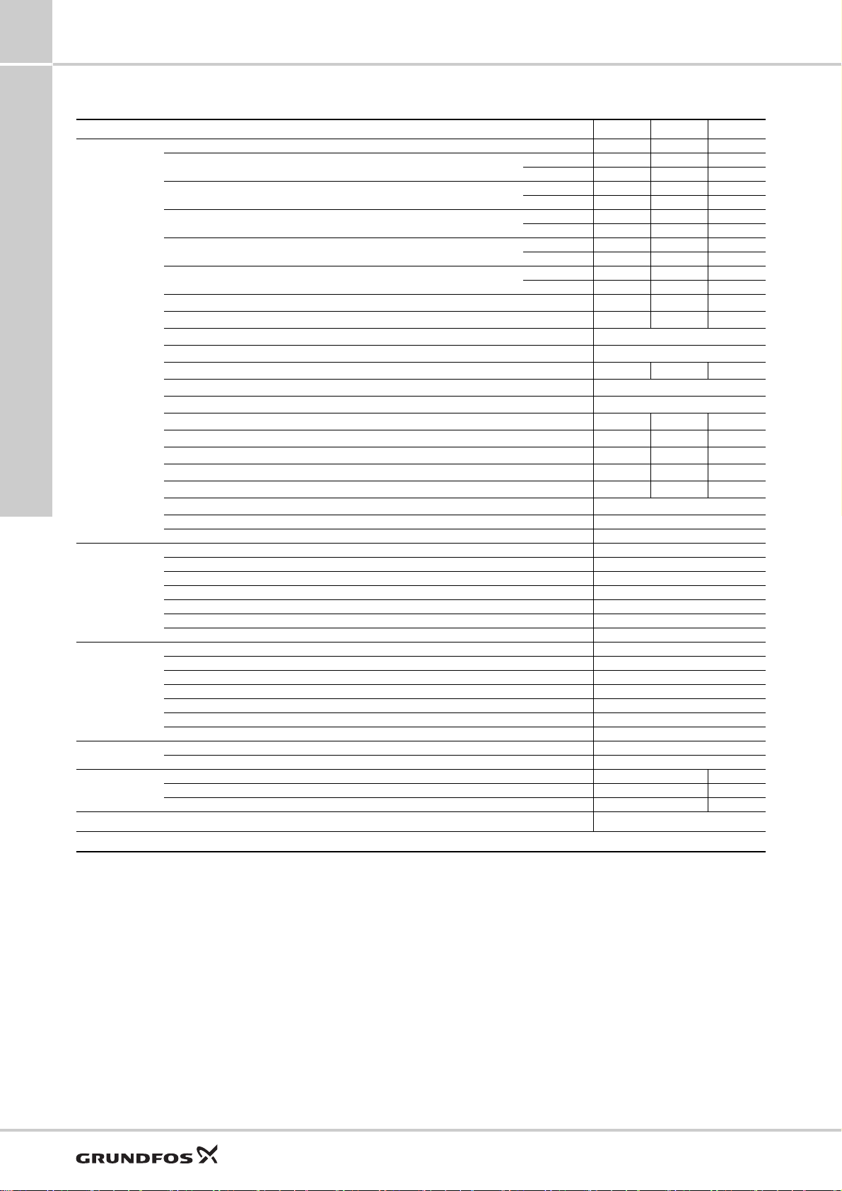
Features at a glance
TM06 8988 2417TM04 1662 2610
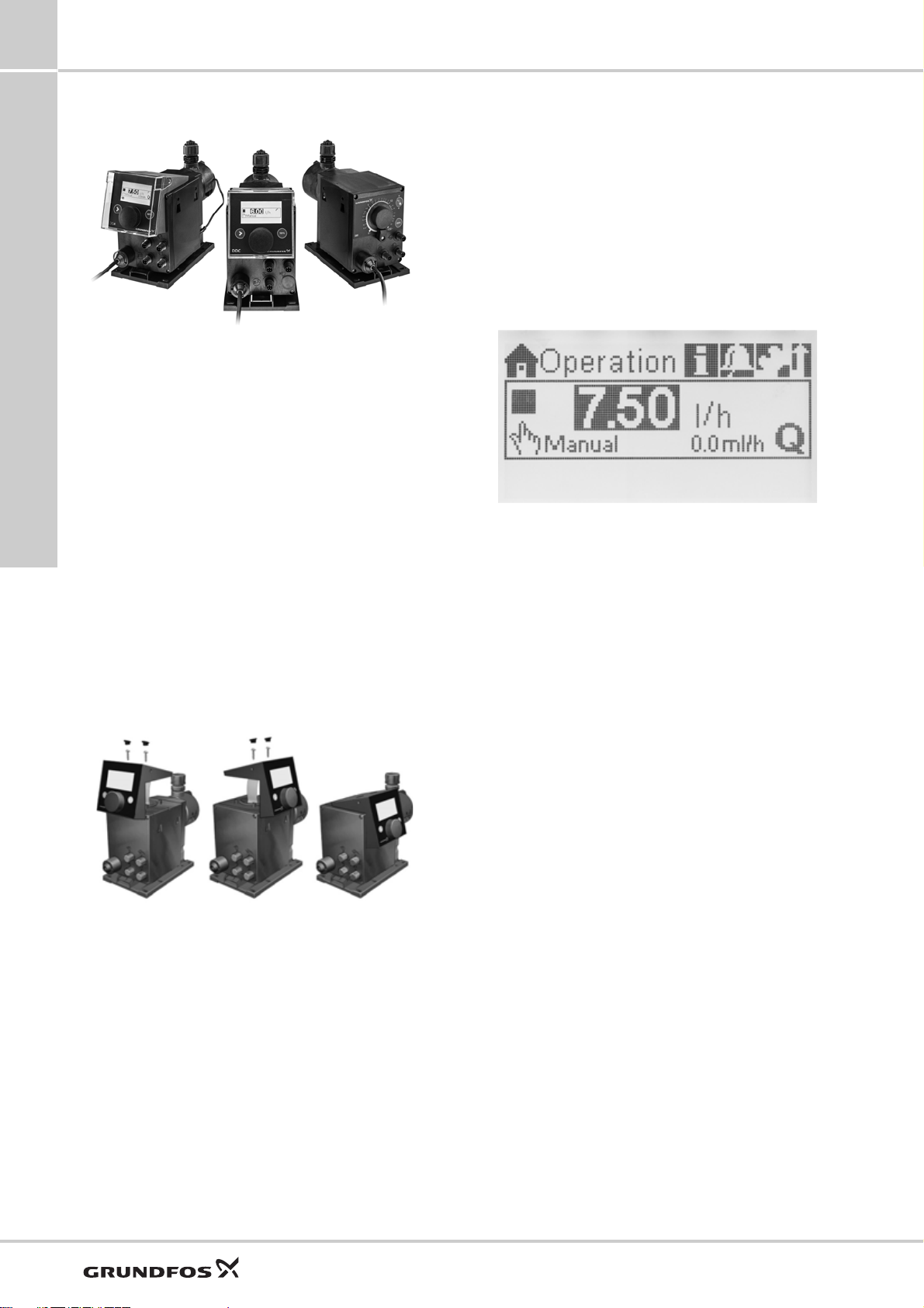
Fig. 2 DDA, DDC, DDE
Digital Dosing
The SMART Digital S generation DDA, DDC and DDE
with powerful variable-speed stepper motor brings
state-of-the-art technology to perfection.
Combined expert knowledge and the patented
solutions set future standards. Traditional technologies
such as stroke length or stroke frequency adjustment
with synchronous motor or solenoid drive become a
thing of the past.
Unique flexibility with only a few variants
The included click-stop mounting plate makes the
pump more flexible. Three different positions are
possible without using any additional accessories,
such as wall brackets. Service and pump exchange
can now be done easily and fast just by clicking the
pump in and out of the mounting plate.
The control cube on the DDA and DDC pump can be
lifted and turned easily into three different positions:
front, left or right.
Fig. 3 Modularity of the control cube
A turn-down ratio of up to 1:3000, a wide supply
voltage range (100-240 V; 50/60 Hz), combined
connection sets and other features reduce the models
and variants to a minimum.
TM
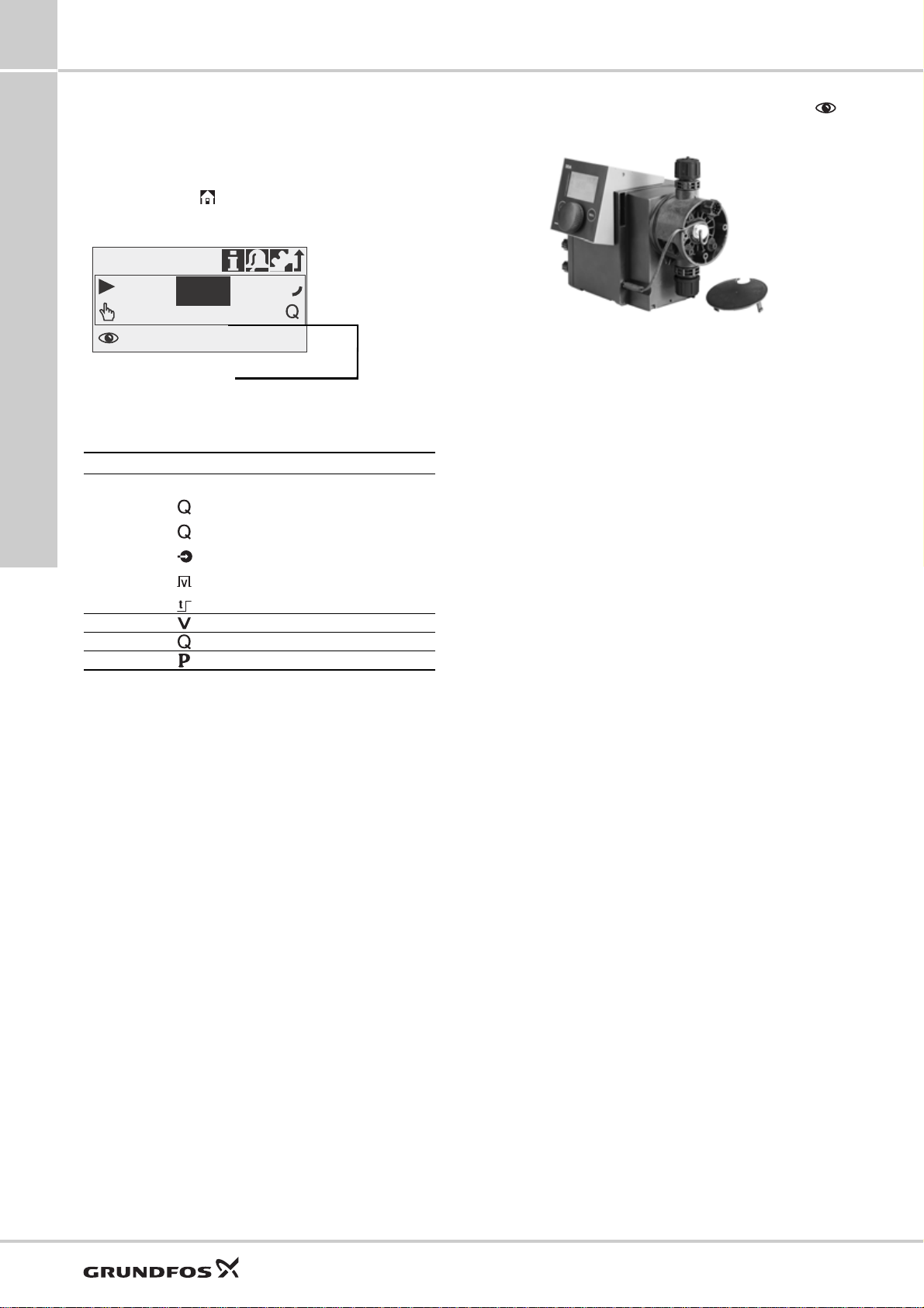
Precise and easy setting / usability and interaction
The operator can easily install the pump and set it to
discharge exactly the quantity of dosing liquid required
for the application. In the display, the setting of the
pump is read out directly, the flow is shown in ml/h, l/h,
or gph.
The click wheel (turn-and-push knob) and the
graphical LC display with plain-text menu in more than
25 languages make commissioning and operation
intuitive. As the LCD is backlit in different colours, the
pump status can be seen from a distance (traffic-light
concept).
TM04 1661 2610
Fig. 4 Display DDA, DDC
Thanks to a variety of operation modes, signal inputs
and outputs, the pump can easily be integrated into
every process.
Advanced process reliability
An intelligent drive and microprocessor control
ensures that dosing is performed precisely and with
low pulsation, even if the pump is dosing high-viscosity
or degassing liquids. Malfunctions, caused e.g. by air
bubbles, are detected quickly by the maintenance-free
FlowControl system and then displayed in the alarm
menu.
The AutoFlowAdapt function automatically adjusts the
pump according to the process conditions, e.g. varying
backpressure. The integrated flow measurement
makes additional monitoring and control equipment
redundant.
Designed to save costs
In general, the investment for a dosing pump
installation is low compared to its life cycle costs
including the cost of the chemicals. The following
features make the SMART Digital S DDA, DDC and
DDE pumps contribute to low life cycle costs:
• No underdosing or overdosing due to high dosing
accuracy and FlowControl
• Longer maintenance intervals thanks to the
universal chemical resistance of the full-PTFE
diaphragm
• Reduced energy consumption thanks to
state-of-the-art drive technology.
4
Page 5

SMART Digital S
Three application-oriented type ranges
DDA: High-end pump range for extended flow and
pressure ranges with sensor-based FlowControl and
measurement functions for challenging industrial
applications, e.g.
• Process water
• Food and beverage
• Ultrafiltration and reverse osmosis
• Pulp and paper
• Boiler feed water
• CIP (Cleaning-In-Place).
DDC: User-friendly pump range with standard inputs
and outputs for common applications, e.g.
• Drinking water
• Waste water
• Swimming pool water
• Cooling tower
• Chemical industry.
DDE: Low-budget pump range with basic functions
including manual operation or control via PLC for OEM
applications, e.g.
•Car wash
• Irrigation.
1
General data
5
Page 6

2
Identification
SMART Digital S
2. Identification
Type key
Example: DDA 7.5-16 AR-PP/V/C-F-3 1 U2U2 F G
Type range
DDA 7.5-16 AR-PP/V/C-F-3 1 U2U2 F G
DDA
DDC
DDE
Max. flow [l/h]
DDA 7.5-16 AR-PP/V/C-F-3 1 U2U2 F G
Maximum pressure [bar]
DDA 7.5-16 AR-PP/V/C-F-3 1 U2U2 F G
Control variant
DDA 7.5-16 AR-PP/V/C-F-3 1 U2U2 F G
BBasic (DDE)
P B with pulse mode (DDE)
PR P with relay output (DDE)
A Standard (DDC)
AR A with alarm relay and analog input (DDA, DDC)
FC AR with FlowControl (DDA)
FCM FC with flow measurement (DDA)
Dosing head variant
DDA 7.5-16 AR-PP/V/C-F-3 1 U2U2 F G
PP Polypropylene
PVC Polyvinyl chloride**
PV PVDF (polyvinylidene fluoride)
SS Stainless steel 1.4401
Gasket material
DDA 7.5-16 AR-PP/V/C-F-3 1 U2U2 F G
E EPDM
VFKM
TPTFE
Valve ball material
DDA 7.5-16 AR-PP/V/C-F-3 1 U2U2 F G
C Ceramic
SS Stainless steel 1.4401
Connection, suction/discharge
DDA 7.5-16 AR-PP/V/C-F-3 1 U2U2 F G
Union nut G 5/8" with parts for hose connection
U2U2
4/6 mm, 6/9 mm, 6/12 mm, 9/12 mm
Union nut G 5/8" with parts for hose connection
U7U7
0.17" x 1/4"; 1/4" x 3/8"; 3/8" x 1/2"
Union nut G 5/8" with threaded connection Rp 1/4",
AA
internal thread
Union nut G 5/8" with threaded connection 1/4" NPT,
VV
internal thread
XX No connections included
*
Hose 4/6 mm (up to 7.5 l/h, 13 bar)
I001
*
Hose 9/12 mm (up to 60 l/h, 9 bar)
I002
*
Hose 0.17" x 1/4" (up to 7.5 l/h, 13 bar)
I003
*
I004
Hose 3/8" x 1/2" (up to 60 l/h, 10 bar)
Mains plug
DDA 7.5-16 AR-PP/V/C-F-3 1 U2U2 F G
FEU
B USA, Canada
GUK
I Australia, New Zealand
E Switzerland
J Japan
L Argentina
Design/approval
DDA 7.5-16 AR-PP/V/C-F-3 1 U2U2 F G
G Grundfos red
A Grundfos green
B Grundfos black
X Neutral/black
C China approval
Special variant
DDA 7.5-16 AR-PP/V/C-F-3 1 U2U2 F GC3
C3 Inspection Certificate 3.1 (EN 10204)
* Installation set: Including 2 pump connections, foot valve, injection
unit, 6 m PE discharge hose, 2 m PVC suction hose, 2 m PVC
deaeration hose (4/6 mm)
** PVC dosing heads only up to 10 bar
Control cube position
DDA 7.5-16 AR-PP/V/C-F-3 1 U2U2 F G
F Front-mounted (change to left and right possible)
X No control cube (DDE)
Supply voltage
DDA 7.5-16 AR-PP/V/C-F-3 1 U2U2 F G
3 1 x 100-240 V, 50/60 Hz
Valve type
DDA 7.5-16 AR-PP/V/C-F-3 1 U2U2 F G
1 Standard
2 Spring-loaded
0.1 bar suction opening pressure
0.1 bar discharge opening pressure
6
Page 7

SMART Digital S
3. Functions
3
Overview of functions
DDA DDC DDE
Control variant: FCM FC AR AR A PR P B
General
Digital Dosing: Internal stroke speed and frequency control ●●●● ●●●●
Mounting plate (basic/wall mounting) ●●●● ●●●●
Control panel, see page 9
Control cube mountable in three positions: front, left, right ●●● ● ●
Control panel position: front-fitted ●●●
Transparent protective cover for control elements ●●● ● ●
Capacity setting in millilitres, litres or US-gallons ●●● ● ●
Graphical display with background light in four colours for status
indication: white, green, yellow, red
Plain-text menu in different languages ●●● ● ●
Turn-and-push knob (click wheel) for easy navigation ●●● ● ●
Capacity adjustment knob (0.1 - 100 %) ●●●
Start/Stop key ●●● ● ●
100 % key (deaearation) ●●●● ●●●
Operation mode switch (manual/pulse) ●●
Operation modes, see page 11
Manual speed control ●●●● ●●●●
Pulse control in ml/pulse ●●● ● ●
Pulse control (1:n) ●●
Analog control 0/4-20 mA ●●● ●
Batch control (pulse-based) ●●●
Dosing timer cycle ●●●
Dosing timer week ●●●
Fieldbus control ●●●
Functions, see page 13
Auto deaeration also during pump standby ●●●
FlowControl system with selective fault diagnosis ●●
Pressure monitoring (min/max) ●●
Flow measurement ●
AutoFlowAdapt ●
SlowMode (anti-cavitation) ●●● ● ●
Calibration mode ●●● ● ●
Scaling of analog input ●●●
Service information display ●●● ● ●
Relay setting: alarm, warning, stroke signal, pump dosing, pulse input* ●●● ● ●
Relay setting (additionally): timer cycle, timer week ●●●
Inputs/outputs, see page 14
Input for external stop ●●●● ●●●
Input for pulse control ●●●● ●●●
Input for analog 0/4-20 mA control ●●● ●
Input for low-level signal ●●●● ●●●
Input for empty tank signal ●●●● ●●●
Output relay (2 relays) ●●● ● ●
Output analog 0/4-20 mA ●●●
Input/Output for GENIbus ●●●
Input/Output for E-box (e.g. E-box 150 with Profibus DP) ●●●
* DDE-PR: relay 1: alarm; relay 2: low-level signal, stroke signal, pulse input
●●● ● ●
Functions
7
Page 8

3
100 %
50 %
10 %
Discharge
Discharge
Discharge
Duration
Duration
Duration
Suction
Suction
Suction
Capacity
setting
Duration
10 %
Discharge
Suction
SlowMode
50 %
Extended suction stroke (SlowMode)
-
-
-
SMART Digital S
Functions
Functional description
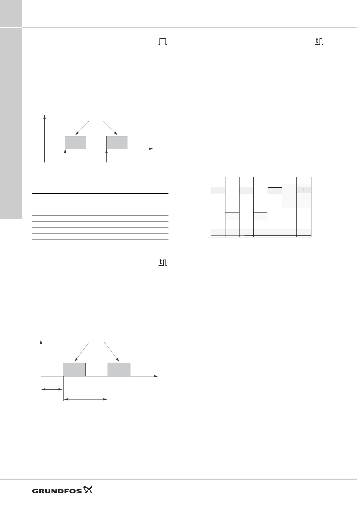
The electronically controlled variable-speed motor
(stepper motor) of the DDA, DDC and DDE pumps
provides optimum control of the stroke speed.
The duration of each discharge stroke varies
according to the capacity set, resulting in optimum
discharge flow in any operating situation, while the
duration of each suction stroke is constant (see figure
below).
The advantages are as follows:
• The pump always operates at full stroke length,
• A capacity range of up to 1:3000 (turn-down ratio)
• Smooth and continuous dosing ensuring an
• Significant reduction of pressure peaks, preventing
• The installation is less affected by long suction and
• Easier dosing of high-viscosity and degassing
The optimum dosing control shown below takes place
in any operation mode.
irrespective of the capacity set; this ensures
optimum accuracy, priming and suction.
reduces variants and spare parts.
optimum mixing ratio at the injection point without
needing static mixers.
mechanical stress on wearing parts such as
diaphragm, tubes, connections, resulting in
extended maintenance intervals.
discharge lines.
liquids (SlowMode).
8
Fig. 5 Relation between stroke-frequency adjustment and capacity
TM04 1481 0410
Page 9

SMART Digital S
7.49 l/h
Manual
7.5
l/h
Operation
1
2
3
4
100%
0%
0.15
0.2
0.3
0.4
0.5
0.6
0.8
1.5
2
3
4
5
6
8
15
20
30
40
50
60
80
10
1
1
3
2
4
5
6
7
100 %
3
Control cube DDA and DDC
DDA and DDC pumps are supplied with front-mounted
control cube. The position of the control cube can
easily be changed by unfastening 2 screws, lifting the
cube, turning it to the left or to the right and fastening
both screws again.
Fig. 6 Two of three possible control cube positions
Operating elements DDA and DDC
Fig. 7 Operating elements DDA and DDC
Pos. Description
1 Graphical LC display
2 [Start/Stop] key
3 Click wheel
4 [100%] key
The click wheel guides the user quickly and easily
through the plain-text menu.
If the maximum capacity is required over a short period
of time, for example during start-up, press the 100 %
key. To set the pump to run for a specific number of
seconds at maximum capacity, press the 100 % key
and turn the click wheel clockwise simultaneously.
Operating elements DDE
Functions
TM04 1596 1817
Fig. 8 Operating elements DDE
TM06 9584 2517TM06 8989 1517
Pos. Description
1 Status LED pulse (DDE-PR and DDE-P)
2 Operation mode switch (DDE-PR and DDE-P)
3 Status LED manual
4 Capacity adjustment knob
5 Logarithmic scale
6 100 % key (DDE-PR and DDE-P)
7 Mechanical lock
With the capacity adjustment knob the capacity of the
pump can easily be adjusted in % of the maximum
flow.
Applies to DDE-PR, DDE-P
When holding down the operation mode switch, the
pump changes from manual operation to pulse mode
or vice versa.
If the maximum capacity is required over a short period
of time, for example during start-up, press the 100 %
key.
Depending on the selected operation mode, the
respective status LED (pulse or manual) is activated
according to the following table:
LED colour Pump status
Green (flashing) Stopped
Green Running
Red-green (flashing) External stop
Yellow Low level (warning)
Red Empty tank (alarm)
Red (flashing) Motor blocked (alarm)
9
Page 10

3
Alarm
1 12.12.2009 13:34
Low level
2
Empty
11.12.2009 14:34
Setup
Language
Operation mode
Analog output
SlowMode
.............................
English >
Manual >
Input >
Off >
Info
Fr 12.12.2009
Counter
Service
Service kit
.............................
12:34
>
-
7.49 l/h
Manual
l/h
Operation
7.50
SMART Digital S
Functions
Menu
The DDA and DDC dosing pumps feature a user-friendly plain-text menu. The menu consists of 4 tabs: Operation;
set to display other languages.
This example applies to DDA pumps:
Info; Alarm; Setup. During initial start-up, all menu text appears in the English language. The menu can be
Fig. 9 Menu overview (example of main menus)
The menu text appears in more than 25 languages on a big graphical display, backlit in four different colours according
to the traffic light concept.
Display Fault Pump status
White - Stop Standby
Green - Running
Yellow Warning Stop Standby Running
Red Alarm Stop Standby
TM04 1553 1210
10
Page 11

SMART Digital S
0
Q [%]
0 - 20 mA
4 - 20 mA
[mA]
4
2081216
100
80
0
60
40
20
Dosing capacity
Input signal
0
Q [%]
[mA]
4 2081216
100
80
0
60
40
20
I / Q
1 1
I / Q
2 2
I ' / Q '
1 1
I ' / Q '
2 2
Dosing capacity
Input signal
3
Operation modes
Manual control
The pump ensures constant dosing according to
the quantity set in l/h or ml/h or gph by means of the
click wheel. The pump automatically changes between
the measuring units.
Setting range
Pump type
DDA 7.5-16 0.0025 7.5
DDA 12-10 0.0120 12.0
DDA 17-7 0.0170 17.0
DDA 30-4 0.0300 30.0
DDC 6-10 0.0060 6.0
DDC 9-7 0.0090 9.0
DDC 15-4 0.0150 15.0
DDE 6-10 0.0060 6.0
DDE 15-4 0.0150 15.0
* When the SlowMode function is enabled the max. flow is reduced
(see page 13)
From [l/h] To [l/h]
Pulse control
The pump doses in proportion to an external
potential-free pulse signal, for example from a water
meter. There is no direct relation between pulses and
dosing strokes. The pump automatically calculates its
optimal speed to ensure that the required quantity is
dosed for each incoming pulse.
Applies to DDA and DDC
The quantity to be dosed is set in ml/pulse. The pump
adjusts its speed according to two factors:
• the frequency of external pulses
• the set quantity per pulse.
Setting range
Pump type Setting range [ml/pulse]
DDA 7.5-16 0.0015 - 14.9
DDA 12-10 0.0029 - 29.0
DDA 17-7 0.0031 - 31.0
DDA 30-4 0.0062 - 62.0
DDC 6-10 0.0016 - 16.2
DDC 9-7 0.0017 - 16.8
DDC 15-4 0.0032 - 31.6
The frequency of external pulses is multiplied by the
set quantity. If the product exceeds the maximum flow
of the pump, a maximum of 65,000 pulses can be
stored for later processing with the Memory pulse
function, when activated.
Setting range*
Applies to DDE-PR, DDE-P control variant
The dosing quantity per pulse is adjusted with the
adjustment knob according to the scale from 0.1 to
100 % of the stroke volume. The pump adjusts its
speed according to two factors:
• the frequency of external pulses
• the set percentage of stroke volume.
Setting range, DDE-PR, DDE-P
Pump type Setting range [ml/pulse]
DDE 6-10 0.0008 - 0.81
DDE 15-4 0.0016 - 1.58
Analog 0/4-20 mA control
Applies to DDA and DDC-AR control variant
The pump ensures dosing according to an external
analog signal. The dosed capacity is proportional to
the input value in mA.
Operation mode Input signal Dosing capacity
4-20
0-20
Fig. 10 0/4-20 mA control
Applies to DDA
With the analog scaling function, the curve can be
individually drawn between two arbitrary points: l
2/Q2
.
and l
≤ 4.1 mA 0 %
≥ 19.8 mA 100 %
≤ 0.1 mA 0 %
≥ 19.8 mA 100 %
1/Q1
Functions
TM04 1574 1410TM04 1575 1410
Fig. 11 Analog scaling
11
Page 12
3
Batch volume
Pulse Pulse
t
1
t
1
Batch volume
t
1
t
1
t
3
t
2
0:00
6:00
12:00
18:00
0:00
33333
3
3
22
1
4
4
11 1
Mo Tu We Th Fr Sa Su
SMART Digital S
Functions
Pulse-based batch control
Applies to DDA
The set quantity is dosed in batches within the set
dosing time (t
receives an external pulse. If the pump receives new
pulses before a batch is completed, these pulses will
be ignored. In the event of interrupts such as external
stop or alarm, incoming pulses will also be ignored.
After ending of the interrupts, a new batch will be
dosed with the next incoming pulse.
Setting range
Pump type
DDA 7.5-16 0.74 999 0.09
DDA 12-10 1.45 999 0.18
DDA 17-7 1.55 999 0.19
DDA 30-4 3.10 999 0.39
* Due to the digital motor control, down to 1/8 of the dosing volume
Dosing timer cycle
Applies to DDA
After a start delay (t
repeatedly dosed in the set cycle time (t3). The dosing
time (t
during any interrupt, e.g. power supply failure or
external stop while the time continues running in the
background (real-time clock). After ending of the
interrupt, batch dosing proceeds according to the
current status in the timeline.
). A batch is dosed every time the pump
1
Fig. 12 Pulse-based batch control
Setting range
From
[ml/batch]
can be dosed.
) can be adjusted. Batch dosing is stopped
1
To [l/batch] Resolution [ml]*
) the set batch volume is
2
Dosing timer week
Applies to DDA
The integrated real-time clock features also batch
dosing based on a weekly period. There is a maximum
of 16 procedures per week. Each dosing procedure
consists of:
• Batch volume
• Dosing time
• Start time
• 1 to 7 weekdays (Monday to Sunday).
In case several procedures are overlapping, the
procedure with the highest flow rate has the highest
priority. Batch dosing is stopped during any interrupt,
e.g. power supply failure or external stop, while the
time continues running in the background (real-time
clock). After ending of the interrupt, batch dosing
proceeds according to the current status in the
timeline.
TM04 1578 2010
TM04 1576 1410
Fig. 14 Dosing timer week (example with 4 procedures)
Setting range
The batch volume setting range corresponds to the
pulse-based batch control setting range.
12
Fig. 13 Dosing timer cycle
Setting range
The batch volume setting range corresponds to the
pulse-based batch control setting range.
TM04 1577 1410
Page 13
SMART Digital S
3
Functions
SlowMode
Applies to DDA, DDC
When the SlowMode function (anti-cavitation) is
selected, the pump extends and smooths its suction
stroke. This results in a softer suction stroke.
The SlowMode function is used in these situations:
• when pumping high-viscosity liquids
• when pumping degassing liquids
• when the suction line is long
• when the suction lift is high.
Depending on the application, the motor speed during
the suction stroke can be reduced individually to
approximately 50 % or 25 % of the normal motor
speed.
The maximum pump capacity is reduced accordingly.
See pages 25 and 26 for further details.
Auto deaeration
Applies to DDA
The auto deaeration function avoids breakdown of the
dosing process due to air-locking, when dosing
degassing liquids such as sodium hypochlorite.
During long dosing breaks, e.g. at the weekend or
overnight, air-bubbles can form in the suction line and
get into the dosing head. If too much air is in the
dosing head, and the dosing process is started again,
no liquid will be dosed (air-lock). Software-controlled
diaphragm movements at regular intervals encourage
the air bubbles to rise and finally to be displaced out of
the dosing head.
These movements are executed
• when the pump is not stopped and
• during dosing breaks (e.g. external stop or no
incoming pulses).
External stop
Applies to DDA, DDC, DDE-PR, DDE-P
With the external stop function, the pump can be
stopped from a remote place via an external contact. It
is not recommended to switch on and off the power
supply as it was usual when working with a
conventional dosing pump. When working with
microprocessor-controlled digital dosing pumps, the
external stop signal has to be used, in order to keep
the optimal dosing precision and to prevent damages
to the electronics.
When activating the external stop signal, the pump
changes from running
to standby . The operation
display shows an activated external stop .
The signal input can be set to normally open (default)
or normally closed contact.
Counters
Applies to DDA and DDC
The pump displays resettable and non-resettable
counters in the info menu tab.
Counter Description Resettable
Volume
Operating
hours
Motor
runtime
Strokes Accumulated number of dosing strokes No
Power on/off
Accumulated dosed quantity in litres or
US gallons
Accumulated number of operating hours
(power-on)
Accumulated number of motor runtime
hours
Accumulated number of times the mains
supply has been switched on
Yes
No
No
No
Functions
Calibration
Applies to DDA and DDC
The pump is calibrated in the factory at the nominal
pressure of the respective pump type (see maximum
pressure Technical data page 25, 26). After start-up,
the dosing pump can be calibrated for the actual
installation to ensure that the displayed value (ml, l or
gph) is correct. A calibration program in the setup
menu facilitates this process. The AutoFlowAdapt
function keeps the dosing precision (DDA-FCM control
variant), even if the backpressure changes.
For the description of the AutoFlowAdapt function, see
page 18.
13
Page 14
3
SMART Digital S
Functions
Service display
Applies to DDA, DDC
Due to the optimised construction and the smooth
digital dosing principle, the service periods are more
than twice as long, if compared to conventional pumps.
However, the wear parts have to be exchanged in
regular intervals in order to keep the dosing precision
and the process reliability at a high level. The service
display in the pump shows when service of the wear
parts is required. The displayed service kit product
number makes service more convenient. The following
information is displayed in the Info display:
Display Description
Service
Service kit
Reset service system
The following service messages appear, depending on
what happens first:
Display
Service soon 7,500 23
Service now 8,000 24
* Applies to DDA only
Soon
Now
8-digit Grundfos
product number
Motor runtime
[h]
No service required
Order parts for service soon
Service must be performed now
The service kit contains all parts
needed for standard maintenance:
diaphragm + valves
After performing the service, reset
the system
Regular intervals
[months]*
Relay output
Applies to DDA, DDC-AR and DDE-PR
The pump can activate 2 external signals by means of
built-in relays switched via internal potential-free
contacts. Depending on the process control
requirements, the following relay output settings can
be chosen:
Applies to DDA and DDC-AR
Signal
Relay 1 Relay 2
Alarm* Alarm
Warning * Warning
Stroke signal Stroke signal Every completed stroke
Pump dosing Pump dosing* Pump is running and dosing
Pulse input Pulse input Every pulse coming in from pulse input
Bus control Bus control
Timer cycle
Timer week
Contact type
NO* NO* Normally Open Contact
NC NC Normally Closed Contact
* default setting
Description
Display red, pump stopped
(e.g. empty tank signal, etc.)
Display yellow, pump running
(low level signal, etc.)
Set by a command in the Bus
communication function (page 15)
(only DDA)
Timer can be set in menu: on-time,
cycle-time, start delay (only DDA)
Timer can be set in menu: procedure,
on-time, start time and weekdays (only
DDA)
In case of difficult liquids the service intervals can be
shorter and service has to be performed earlier.
Level control
Applies to DDA, DDC, DDE-PR and DDE-P
The pump can be connected to a dual level control unit
for monitoring of the chemical level in the tank. The
pump can react to two level signals:
Level sensors
Low-level signal
Empty tank
signal
* Depending on the pump model and settings, the relay outputs can
be activated (see Relay output, page 14)
DDA, DDC DDE-PR, DDE-P
• Display is yellow
(Warning)
• is flashing
• Pump continues
running
• Display is red (Alarm)
• is flashing
• Pump stops
Pump reaction*
• LED lights up in
yellow
• Pump continues
running
• LED lights up in red
• Pump stops
Applies to DDE-PR control variant
Signal
Relay 1 Relay 2
Alarm* Empty tank, motor blocked
Low level* Low level tank
Stroke signal Every completed stroke
Pulse input Every pulse coming in from pulse input
Contact type
NO* NO* Normally Open Contact
NC NC Normally Closed Contact
* default setting
Description
14
Page 15

SMART Digital S
100%
100%
3
Analog output
Applies to DDA
In addition to the analog input (operation mode: analog
0/4-20 mA) the pump is also equipped with an analog
0/4-20 mA output signal. Depending on the process
control requirements, the following analog output
settings are available:
Setting
Output = Input
Actual flow
Backpressure
Bus control
* Output signal is calculated based on motor speed and pump status
(target flow rate).
Description of analog
output signal
Analog feedback signal (not
for master-slave application).
The analog input signal is
mapped 1:1 to the analog
output.
Flow measured in the dosing
head
(Flow Measurement page 18)
Backpressure measured in
the dosing head
(Pressure monitoring page 18)
Set by a command in the bus
communication (see below)
Control variant
FCM FC AR
XXX
XX*X*
XX
XXX
Bus communication
Applies to DDA
The pump is equipped with a built-in module for
GENIbus communication. With the additional E-Box
module (please see page 36) the pump can be
integrated into a fieldbus network.
The bus communication possibilities enable remote
monitoring and setting via the fieldbus system.
Key lock and mechanical lock
Applies to DDA, DDC
To protect the pump from maloperation, a key lock can
be set by entering a 4-digit PIN-code. When the pump
is locked, it is still possible to navigate through the
menus Alarm and Info and to acknowledge
alarms. Two levels of protection are available:
• Settings: the keys and are still available.
• Settings + keys: the keys and are also
locked.
For temporary (2 minutes) or final deactivation the
preset 4-digit pin-code has to be entered again.
Applies to DDE
The adjustment knob can be locked with a locking
screw to fix the current setting.
Basic settings
Applies to DDA, DDC
With load factory settings, the pump can be reset to
the default settings. In addition, with save customer
settings, the current configuration of the pump is
stored and can be activated later by load customer
settings. The latest saved configuration is stored in the
memory.
Units
Applies to DDA, DDC
It is possible to select metric units (litre/millilitre/bar) or
US units (US gallons/psi). Depending on the operation
mode and menu, the following units are displayed:
Functions
Fig. 15 DDA with E-box
Operation mode/Function M etric units US units
Manual control ml/h or l/h gph
Pulse control ml/ ml/
Analog 0/4-20 mA control ml/h or l/h gph
Batch control
(pulse- or timer-based)
Calibration ml ml
Volume counter l gal
Pressure monitoring bar psi
TM04 1640 2617
ml or l gal
15
Page 16
3
7.49 l/h
Manual
7.50
l/h
Operation
Additional display
SMART Digital S
Functions
Additional display
Applies to DDA, DDC
The additional display function provides further useful
status information, e.g. the target flow rate as well as
the actual flow rate. The value is shown in the
operation display together with the corresponding
symbol.
The following additional information can be selected:
Settings Description
Default display
Dosed volume
Actual flow
Backpressure
1) Only DDA-FCM control variant
2) Only DDA-FCM/FC control variant
3) Only DDA pumps
4) Only DDA pumps and DDC-AR control variant
Fig. 16 Additional display
Depending on the operation mode:
Actual flow (manual, pulse)
Target flow (pulse)
Input current (analog)
Remaining batch volume (batch, timer)
Time until next batch (timer)
Total dosed volume (Counters see page 13)
Actually measured flow
Current backpressure in the dosing head
FlowControl
Applies to DDA-FC/FCM
TM04 1641 2617
Fig. 17 DDA FlowControl
The pump monitors the dosing process of liquids when
TM04 1633 1810
1)
4)
3)
3)
1)
2)
the FlowControl function is activated. Although the
pump is still operating, some influences such as air
bubbles may cause reduced flow rates or even stop
the dosing process. For optimal process safety and
reliability, the activated FlowControl function
immediately detects and displays the following
malfunctions:
• Overpressure
• Discharge line burst
• Air bubbles in the dosing head
• Cavitation at the suction side
• Suction valve leakage
• Discharge valve leakage.
The unique FlowControl is based on an intelligent and
maintenance-free sensor integrated in the dosing
head. During the dosing process, the sensor measures
the actual pressure and sends the measured value to
the microprocessor in the pump. An internal indicator
diagram is generated combining the actual pressure
value with the diaphragm position (stroke length).
With it, the dosing process is monitored, as the
different malfunctions can immediately be detected
due to their specific deviations in the curve.
Compressible air bubbles, for instance, will reduce the
discharge phase and the stroke volume (see fig. 18).
The sensitivity and the delay of the FlowControl
function can be adjusted individually.
FlowControl requires a minimum backpressure of
2 bar. Grundfos recommend an additional
spring-loaded valve (approx. 3 bar) on the discharge
side for dosing low capacities (< 1 l/h) (please see
page 46).
16
Page 17

SMART Digital S
1
2
3
4
Pressure
Stroke length
Trouble-free dosing stroke
Air bubbles disturbing
the dosing stroke
3
Functions
TM04 1610 1710
Fig. 18 Indicator diagram
1 Compression phase
2 Discharge phase
3 Expansion phase
4 Suction phase
17
Page 18

3
SMART Digital S
Functions
Pressure monitoring
Applies to DDA-FC/FCM
The integrated pressure sensor measures the actual
pressure of the system, which is shown in the display.
A maximum pressure can be set. If the pressure in the
system exceeds the set maximum (e.g. caused by a
closed valve), the pressure monitoring function stops
the dosing process immediately. As soon as the
backpressure falls below the set maximum, the dosing
process is continued. In case the pressure drops below
the minimum limit (e.g. caused by a burst discharge
line) the pump stops and major chemical spills are
prevented.
Pressure setting range
Pump type
DDA 7.5-16 < 2 3 ... 17 (default)
DDA 12-10 < 2 3 ... 11 (default)
DDA 17-7 < 2 3 ... 8 (default)
DDA 30-4 < 2 3 ... 5 (default)
* Can be either set as a warning (pump keeps running) or as an
** The adjustable max. pressure is equivalent to the max. operating
Flow measurement
Applies to DDA-FCM
The pump can precisely measure and display the
actual dosing flow. Via the analog 0/4-20 mA output,
the actual flow signal can easily be integrated in any
process control system, without needing any additional
measurement equipment.
The Flow measurement function is based on an
indicator diagram as described in FlowControl
(page 16). Accumulating the length of each discharge
stroke phase and multiplying it with the stroke
frequency results in the displayed actual flow.
Any malfunctions, such as air bubbles or lower
backpressure, will result in a reduced or increased
actual flow rate. When the AutoFlowAdapt function
(page 18) is activated, the pump compensates these
influences by correcting the stroke speed.
Fixed min. pressure
alarm (pump stops)
pressure plus 1 bar
[bar]*
Adjustable max. pressure
[bar]**
AutoFlowAdapt
Applies to DDA-FCM
When activating the AutoFlowAdapt function even
environmental changes will be compensated, so that
the required target flow rate will be achieved.
The integrated AutoFlowAdapt makes additional
monitoring and control devices redundant.
The AutoFlowAdapt function is based on:
• FlowControl: malfunctions are detected
• Pressure monitoring: system pressure changes are
detected
• Flow measurement: deviations in the target flow are
detected.
Examples:
• FlowControl detects air bubbles in the system.
Due to a special motor drive strategy and a certain
speed increase, the pump will try to keep the flow
rate constant. This is especially important when
dosing degassing liquids.
• In general, increasing system pressure reduces the
stroke volume whereas falling system pressure
increases the stroke volume. The AutoFlowAdapt
function compensates this by automatically and
continuously adapting the motor speed.
Despite fluctuating system pressure, dosing
accuracy is maintained.
18
Page 19

SMART Digital S
2
1
3
4
2
1
3
4
5
2
3
4
1
2
1
3
►
2
1
GND
GND
BUS
BUS
GND
12
34
12
34
12
5
34
34
12
Cable 1
Analog/external stop/pulse
Product No.
2 m cable: 96609014
5 m cable: 96609016
Cable 2
Level input
see page 39, suction
lances
Cable 3
GENIbus, analog output
Product No.
2 m cable: 96632921
5 m cable: 96632922
Cable 4
Relay output
Product No.
2 m cable: 96609017
5 m cable: 96609019
FlowControl input
Sensor
Wiring diagram, DDA
3
Functions
Cable 1: Analog, external stop and pulse input
Function
Analog GND/ (-) mA (+) mA mA signal
External stop GND X Contact
Pulse GND X Contact
1/brown 2/white 3/blue 4/black
Cable 2: Level input
Function
Low level X GND Contact
Empty tank X GND Contact
1234
Cable 3: GENIbus, analog output
Function
GENIbus +30 V GENI bus A GENI bus B GND Bus
Analog output (+) mA GND/ (-) mA mA signal
1/brown 2/white 3/blue 4/black 5/yellow-green
Cable 4: Relay output
Function
Relay 1 X X Contact
Relay 2 X X Contact
1/brown 2/white 3/blue 4/black
Pin holes
Pin holes
Pin holes
Pin holes
TM04 1121 0110 - TM06 8987 1517
Plug type
Plug type
Plug type
Plug type
19
Page 20

3
2
1
3
4
►
GND
12
34
34
12
2
3
4
1
1
2
12
34
2
1
3
GND
Cable 1
Analog/external stop/pulse
Product No.
2 m cable: 96609014
5 m cable: 96609016
Cable 2
Level input
see page 39, suction
lances
Cable 4
Relay output
Product No.
2 m cable: 96609017
5 m cable: 96609019
SMART Digital S
Functions
Wiring diagram, DDC
Cable 1: Analog, external stop and pulse input
Function
Analog* GND/ (-) mA (+) mA mA signal
External stop GND X Contact
Pulse GND X Contact
Cable 2: Level input
Function
Low level X GND Contact
Empty tank X GND Contact
Cable 4: Relay output*
Function
Relay 1 X X Contact
* applies to DDC-AR
Relay 2 X X Contact
Pin holes
1/brown 2/white 3/blue 4/black
Pin holes
1234
Pin holes
1/brown 2/white 3/blue 4/black
TM04 1531 1010
Plug type
Plug type
Plug type
20
Page 21

SMART Digital S
1
3
4
2
3
4
1
2
1
3
Ź
2
1
GND
GND
12
34
34
12
12
34
Cable 2
Level input
see page 39, suction
lances
Cable 1
External stop/pulse
Product No.
2 m cable: 96609014
5 m cable: 96609016
Cable 4
Relay output
Product No.
2 m cable: 96609017
5 m cable: 96609019
Wiring diagram, DDE-PR, -P
3
Functions
Cable 1: External stop and pulse input
Function
External stop GND X Contact
Pulse GND X Contact
1/brown 2/white 3/blue 4/black
Cable 2: Level input
Function
Low level X GND Contact
Empty tank X GND Contact
Cable 4: Relay output*
Function
Relay 1 (Alarm) X X Contact
Relay 2 (see page 14) X X Contact
* applies to DDE-PR
1/brown 2/white 3/blue 4/black
Pin holes
Pin holes
1234
Pin holes
TM04 1597 0312
Plug type
Plug type
Plug type
21
Page 22

4
1
2
3
4
5
6
7
8
9
13
14
15 16
17
23
24
25
26
27
28
29
18 19
20
21
22
10
11
12
Construction
SMART Digital S
4. Construction
DDA and DDC
TM04 1533 1010
Fig. 19 Sectional drawing, DDA
Construction
The DDA and DDC pumps are motor-driven diaphragm
dosing pumps consisting of the following main parts:
Dosing head: Patented design with a minimum of
clearance space optimised for degassing liquids.
With integrated deaeration valve for priming and
venting complete with connection for a 4/6 mm or 0.17"
x 1/4" tubing. DDA-FCM/FC pumps have an integrated
pressure sensor in the dosing head.
Valves: Double-ball discharge and suction valve*
design for less clearance space - optimised for
degassing liquids. Spring-loaded valves for higher
viscosities are available as an option.
Connections: Robust and easy-to-use connection
packages for various sizes of tubing or pipes.
Diaphragm: Full PTFE diaphragm designed for long
life and universal chemical resistance.
Flange: With separation chamber, safety diaphragm
and drain hole.
Drive unit: Positive return crank with patented
noiseless spur gear drive, energy recovery spring for
high efficiency (only DDA), stepper motor, all mounted
in a robust gear housing.
Control cube: Containing operation electronics with
display, keys, click-wheel and protective cover.
Housing: Containing drive unit and power electronics
with robust signal sockets. The housing can be clicked
on the mounting plate.
22
Material specification
Pos. Description Material options
1 Stepper motor 2 Cooling element** Aluminium
3 Suction valve, complete *** -
4 Valve ball, DN 4*
5 Dosing head PP, PVC, PVDF, SS 1.4435
6 Safety diaphragm EPDM
7 Dosing head screw SS 1.4301
8 Diaphragm full PTFE
9 Pressure sensor 10 Dosing head cover PP, SS 1.4301
11 Deaeration valve PP, PVC, PVDF
12 Deaeration valve O-ring EPDM/FKM
13 Discharge valve, complete*** 14 Discharge valve O-ring EPDM, FKM, PTFE
15 Discharge valve ball, DN 8
16 Discharge valve seat EPDM, FKM, PTFE
17 Discharge valve ball cage PP, PVC, PVDF, SS 1.4435
18 Flange PPO/PS 20 % gf
19 Energy recovery spring** EN 10270-2/VD SiCr
20 Connecting rod PA 6.6 30 % gf
21 Gear box PPO/PS 20 % gf
22 Housing PPO/PS 20 % gf
23 Control cube PPO/PS 20 % gf
24 Display cover PC
25 Operation PCB 26 Click wheel PPO/PS 20 % gf
27 Hall sensor 28 Power PCB 29 Mounting plate PPO/PS 20 % gf
* Only for pumps up to 7.5 l/h with standard valves
** Only for DDA
*** Pump can be supplied with spring-loaded valves (Material: Tantal)
Ceramic Al
SS 1.4401
Ceramic Al
SS 1.4401
2O3
2O3
99.5 %,
99.5 %,
Page 23

SMART Digital S
DDE
4
11
10
9
8
7
6
5
4
3
2
1
12
13 15
14
16
Fig. 20 Sectional drawing, DDE
Construction
The DDE pump is a motor-driven diaphragm dosing
pump consisting of the following main parts:
Dosing head: Patented design with a minimum of
clearance space optimised for degassing liquids.
With integrated deaeration valve for priming and
venting complete with connection for a 4/6 mm or 0.17"
x 1/4" tubing.
Valves: Double-ball discharge and suction valve*
design for less clearance space - optimised for
degassing liquids. Spring-loaded valves for higher
viscosities are available as an option.
Connections: Robust and easy-to-use connection
packages for various sizes of tubing or pipes.
Diaphragm: Full PTFE diaphragm designed for long
life and universal chemical resistance.
Flange: With separation chamber, safety diaphragm
and drain hole.
Drive unit: Positive return crank with patented
noiseless spur gear drive, stepper motor, all mounted
in a robust gear housing.
Housing: Containing drive unit, control panel and
electronics with robust signal sockets. The housing
can be clicked on the mounting plate.
18
17
19
20
Construction
21
22
23
TM04 1609 1710
Material specification
Pos. Description Material options
1 Stepper motor -
2 Suction valve, complete ** -
3 Valve ball, DN 4*
4 Dosing head PP, PVC, PVDF, SS 1.4435
5 Safety diaphragm EPDM
6 Dosing head screw SS 1.4301
7 Diaphragm full PTFE
8 Dosing head cover PP, SS 1.4301
9 Deaeration valve PP, PVC, PVDF
10 Deaeration valve O-ring EPDM/FKM
11 Discharge valve, complete** 12 Discharge valve O-ring EPDM, FKM, PTFE
13 Discharge valve ball, DN 8
14 Discharge valve ball cage PP, PVC, PVDF, SS 1.4435
15 Discharge valve seat EPDM, FKM, PTFE
16 Flange PPO/PS 20 % gf
17 Connecting rod PA 6.6 30 % gf
18 Gear box PPO/PS 20 % gf
19 Housing PPO/PS 20 % gf
20 Hall sensor 21 Capacity adjustment knob PPO/PS 20 % gf
22 Power PCB 23 Mounting plate PPO/PS 20 % gf
* Only for pumps up to 6 l/h with standard valves
** Pump can be supplied with spring-loaded valves (Material: Tantal)
Ceramic Al
SS 1.4401
Ceramic Al
SS 1.4401
2O3
2O3
99.5 %,
99.5 %,
23
Page 24

5
100%
110
17.5
168
161
D
B
C
A1
G 5/8
A
200.8
17
161 17D
A1
B
C
161.5
G 5/8
4 x Ø6
110
105
120
17.5
Dimensions
SMART Digital S
5. Dimensions
DDA and DDC
4 x Ø6
105
120
Fig. 21 DDA and DDC with front-fitted or side-fitted control cube
DDE
TM04 1487 0710
24
Fig. 22 DDE-PR with front-fitted control elements
Pump type A [mm] A1 [mm] B [mm] C [mm] D [mm]
DDA 7.5-16
DDC 6-10
DDC 9-7
DDE 6-10
DDA 12-10
DDA 17-7
DDC 15-4
DDE 15-4
DDA 30-4 295 267 204.5 35.5 38.5
280 251 196 46.5 24
280 251 200.5 39.5 24
TM04 1598 0312
Page 25

SMART Digital S
6. Technical data
DDA
6
DDA 7.5-16 12-10 17-7 30-4
Turn-down ratio (setting range) [1:X] 3000 1000 1000 1000
Max. dosing capacity
Max. dosing capacity with SlowMode 50 %
Max. dosing capacity with SlowMode 25 %
Min. dosing capacity
Max. operating pressure
Max. stroke frequency
Stroke volume
Mechanical data
Electrical data
Signal input
Signal output
Weight/size
Sound pressure Max. sound pressure level [dB(A)] 60
Approvals CE, CB, CSA-US, NSF61, EAC, ACS, C-Tick
1) The maximum stroke frequency varies depending on calibration
2) Data is based on measurements with water
3) Maximum suction lift: 1 m, dosing capacity reduced (approx. 30 %)
4) Length of suction line: 1.5 m, length of discharge line: 10 m (at max. viscosity)
5) With E-box
Accuracy of repeatability
Max. suction lift during operation
Max. suction lift when priming with wet valves
Min. pressure difference between suction and discharge side
Max. inlet pressure, suction side
Max. viscosity in SlowMode 25 % with spring-loaded valves
Max. viscosity in SlowMode 50 % with spring-loaded valves
Max. viscosity without SlowMode with spring-loaded valves
Max. viscosity without spring-loaded valves
Min. internal hose/pipe diameter suction/discharge side
Min. internal hose/pipe diameter suction/discharge side (high viscosity)
Min./Max. liquid temperature [°C] -10/45
Min./Max. ambient temperature [°C] 0/45
Voltage [V] 100-240 V, 50/60 Hz
Length of mains cable [m] 1.5
Max. inrush current for 2 ms at 100 V [A] 8
Max. inrush current for 2 ms at 230 V [A] 25
Max. power consumption P
Enclosure class IP65, Nema 4X
Electrical safety class II
Max. load low-level / empty tank / pulse / external stop input 12 V, 5 mA
Min. pulse length [ms] 5
Max. pulse frequency [Hz] 100
Impedance at analog 0/4-20 mA input [Ω]15
Accuracy of analog input (full-scale value) [%] ± 1.5
Min. resolution of analog input [mA] 0.05
Max. resistance in level/pulse circuit [Ω] 1000
Max. ohmic load on relay output [A] 0.5
Max. voltage on relay/analog output [V] 30 VDC/30 VAC
Impedance at 0/4-20 mA analog output [Ω]500
Accuracy of analog output (full-scale value) [%] ± 1.5
Min. resolution of analog output [mA] 0.02
Weight (PVC, PP, PVDF) [kg] 2.4 2.4 2.6
Weight (stainless steel) [kg] 3.2 3.2 4.0
Diaphragm diameter [mm] 44 50 74
1)
2)
2)
3)
3)
3)
3)
4), 2)
4)
1
[l/h] 7.5 12.0 17.0 30.0
[gph] 2.0 3.1 4.5 8.0
[l/h] 3.75 6.00 8.50 15.00
[gph] 1.00 1.55 2.25 4.00
[l/h] 1.88 3.00 4.25 7.50
[gph] 0.50 0.78 1.13 2.00
[l/h] 0.0025 0.0120 0.0170 0.0300
[gph] 0.0007 0.0031 0.0045 0.0080
[bar] 16 ★ 10 7 4
[psi] 230 150 100 60
[strokes/min] 190 155 205 180
[ml] 0.74 1.45 1.55 3.10
[%] ± 1
[m] 6
[m] 2332
[bar] 1 (FC and FCM: 2)
[bar] 2
[mPas] (= cP) 2500 2500 2000 1500
[mPas] (= cP) 1800 1300 1300 600
[mPas] (= cP) 600 500 500 200
[mPas] (= cP) 50 300 300 150
[mm] 4 6 6 9
[mm] 9
[W]
★ Max. pressure for PVC version: 10 bar
24
5)
Technical data
25
Page 26
6
SMART Digital S
Technical data
DDC
DDC 6-10 9-7 15-4
Turn-down ratio (setting range) [1:X] 1000 1000 1000
Max. dosing capacity
Max. dosing capacity with SlowMode 50 %
Max. dosing capacity with SlowMode 25 %
Min. dosing capacity
Max. operating pressure
Max. stroke frequency
Stroke volume
Mechanical data
Electrical data
Signal input
Signal output
Weight/size
Sound pressure Max. sound pressure level [dB(A)] 60
Approvals CE, CB, CSA-US, NSF61, EAC, C-Tick
1) The maximum stroke frequency varies depending on calibration
2) Data is based on measurements with water
3) Maximum suction lift: 1 m, dosing capacity reduced (approx. 30 %)
4) Length of suction line: 1.5 m, length of discharge line: 10 m (at max. viscosity)
Accuracy of repeatability
Max. suction lift during operation
Max. suction lift when priming with wet valves
Min. pressure difference between suction and discharge side
Max. inlet pressure, suction side
Max. viscosity in SlowMode 25 % with spring-loaded valves
Max. viscosity in SlowMode 50 % with spring-loaded valves
Max. viscosity without SlowMode with spring-loaded valves
Max. viscosity without spring-loaded valves
Min. internal hose/pipe diameter suction/discharge side
Min. internal hose/pipe diameter suction/discharge side (high viscosity)
Min./Max. liquid temperature [°C] -10/45
Min./Max. ambient temperature [°C] 0/45
Voltage AC [V] 100-240 V, 50/60 Hz
Length of mains cable [m] 1.5
Max. inrush current for 2 ms at 100 V [A] 8
Max. inrush current for 2 ms at 230 V [A] 25
Max. power consumption P
Enclosure class IP65, Nema 4X
Electrical safety class II
Max. load low-level / empty tank / pulse / external stop input 12 V, 5 mA
Min. pulse length [ms] 5
Max. pulse frequency [Hz] 100
Impedance at analog 0/4-20 mA input [Ω]15
Accuracy of analog input (full-scale value) [%] ± 1.5
Min. resolution of analog input [mA] 0.05
Max. resistance in level/pulse circuit [Ω] 1000
Max. ohmic load on relay output [A] 0.5
Max. voltage on relay output [V] 30 VDC/30 VAC
Weight (PVC, PP, PVDF) [kg] 2.4 2.4
Weight (stainless steel) [kg] 3.2 3.2
Diaphragm diameter [mm] 44 50
1)
2)
2)
3)
3)
3)
3)
4), 2)
4)
1
[l/h] 6.0 9.0 15.0
[gph] 1.5 2.4 4.0
[l/h] 3.00 4.50 7.50
[gph] 0.75 1.20 2.00
[l/h] 1.50 2.25 3.75
[gph] 0.38 0.60 1.00
[l/h] 0.0060 0.0090 0.0150
[gph] 0.0015 0.0024 0.0040
[bar] 10 7 4
[psi] 150 100 60
[strokes/min] 140 200 180
[ml] 0.81 0.84 1.58
[%] ± 1
[m] 6
[m] 2 2 3
[bar] 1
[bar] 2
[mPas] (= cP) 2500 2000 2000
[mPas] (= cP) 1800 1300 1300
[mPas] (= cP) 600 500 500
[mPas] (= cP) 50 50 300
[mm] 4 6 6
[mm] 9
[W] 22
26
Page 27

SMART Digital S
DDE
DDE 6-10 15-4
Turn-down ratio (setting range) [1:X] 1000 1000
Max. dosing capacity
Min. dosing capacity
Max. pressure
Max. stroke frequency
Stroke volume [ml] 0.81 1.58
Accuracy of repeatability [%] ± 5
Mechanical data
Electrical data
Signal input
Signal output
Weight/size
Sound pressure Max. sound pressure level [dB(A)] 60
Approvals CE, CB, CSA-US, NSF61, EAC, C-Tick
1) Data is based on measurements with water
2) Maximum suction lift: 1 m, dosing capacity reduced (approx. 30 %)
3) Length of suction line: 1.5 m, length of discharge line: 10 m (at max. viscosity)
Max. suction lift during operation
Max. suction lift when priming with wet valves
Min. pressure difference between suction and discharge side
Max. inlet pressure, suction side
Max. viscosity with spring-loaded valves
Max. viscosity without spring-loaded valves
Min. internal hose/pipe diameter suction/discharge side
Min. internal hose/pipe diameter suction/discharge side (HV)
Min./Max. liquid temperature [°C] -10/45
Min./Max. ambient temperature [°C] 0/45
Voltage [V] 100-240 V, 50/60 Hz
Length of mains cable [m] 1.5
Max. inrush current for 2 ms at 100 V [A] 8
Max. inrush current for 2 ms at 230 V [A] 25
Max. power consumption P
Enclosure class IP65, Nema 4X
Electrical safety class II
Max. load low-level / empty tank / pulse / external stop input 12 V, 5 mA
Min. pulse length [ms] 5
Max. pulse frequency [Hz] 100
Max. resistance in level/pulse circuit [Ω] 1000
Max. ohmic load on relay output [A] 0.5
Max. voltage on relay output [V] 30 VDC/30 VAC
Weight (PVC, PP, PVDF) [kg] 2.4 2.4
Weight (stainless steel) [kg] 3.2 3.2
Diaphragm diameter [mm] 44 50
1)
1)
2)
2)
1), 3)
3)
1
[l/h] 6.0 15.0
[gph] 1.5 4.0
[l/h] 0.0060 0.0150
[gph] 0.0015 0.0040
[bar] 10 4
[psi] 150 60
[strokes/min] 140 180
[m] 6
[m] 2 3
[bar] 1
[bar] 2
[mPas] (= cP) 600 500
[mPas] (= cP) 50 50
[mm] 4 6
[mm] 9
[W] 19
6
Technical data
27
Page 28
7
Pump selection
7. Pump selection
DDA, standard range
Power supply: 1 x 100-240 V, 50/60 Hz (switch mode)
Mains plug: EU
Valves: Standard
Connection set: U2U2 / I001 / AA (see Type key on page 6)
SMART Digital S
Max.
flow
[l/h]
7.5 16
12 10
17 7
30 4
* Installation set includes: 2 pump connections, foot valve, injection unit, 6 m PE discharge hose, 2 m PVC suction hose, 2 m PVC deaeration hose
** Also available in FC- and FCM-control version
*** PVC dosing heads only up to 10 bar
(4/6 mm)
Max.
pressure
[bar]
Dosing
head
PVC***
PVDF PTFE Ceramic
PVDF PTFE Ceramic
PVDF PTFE Ceramic
PVDF PTFE Ceramic
Materials
Gaskets
EPDM Ceramic
PP
FKM Ceramic
EPDM Ceramic
FKM Ceramic
SS PTFE SS 1.4401 No DDA 7.5-16 AR-SS/T/SS-F-31AAFG 97721970 97722004 97722038
EPDM Ceramic
PP
FKM Ceramic
EPDM Ceramic
PVC
FKM Ceramic
SS PTFE SS 1.4401 No DDA 12-10 AR-SS/T/SS-F-31AAFG 97722072 97722106 97722140
EPDM Ceramic
PP
FKM Ceramic
EPDM Ceramic
PVC
FKM Ceramic
SS PTFE SS 1.4401 No DDA 17-7 AR-SS/T/SS-F-31AAFG 97722174 97722208 97722242
EPDM Ceramic
PP
FKM Ceramic
EPDM Ceramic
PVC
FKM Ceramic
SS PTFE SS 1.4401 No DDA 30-4 AR-SS/T/SS-F-31AAFG 97722276 97722311 97722355
Valve
balls
Installation
set*
Type designation**
No DDA 7.5-16 AR-PP/E/C-F-31U2U2FG 97721938 97721972 97722006
Yes DDA 7.5-16 AR-PP/E/C-F-31I001FG 97721939 97721973 97722007
No DDA 7.5-16 AR-PP/V/C-F-31U2U2FG 97721942 97721976 97722010
Yes DDA 7.5-16 AR-PP/V/C-F-31I001FG 97721943 97721977 97722011
No DDA 7.5-16 AR-PVC/E/C-F-31U2U2FG 97721946 97721980 97722014
Yes DDA 7.5-16 AR-PVC/E/C-F-31I001FG 97721947 97721981 97722015
No DDA 7.5-16 AR-PVC/V/C-F-31U2U2FG 97721950 97721984 97722018
Yes DDA 7.5-16 AR-PVC/V/C-F-31I001FG 97721951 97721985 97722019
No DDA 7.5-16 AR-PV/T/C-F-31U2U2FG 97721966 97722000 97722034
Yes DDA 7.5-16 AR-PV/T/C-F-31I001FG 97721967 97722001 97722035
No DDA 12-10 AR-PP/E/C-F-31U2U2FG 97722040 97722074 97722108
Yes DDA 12-10 AR-PP/E/C-F-31I002FG 97722041 97722075 97722109
No DDA 12-10 AR-PP/V/C-F-31U2U2FG 97722044 97722078 97722112
Yes DDA 12-10 AR-PP/V/C-F-31I002FG 97722045 97722079 97722113
No DDA 12-10 AR-PVC/E/C-F-31U2U2FG 97722048 97722082 97722116
Yes DDA 12-10 AR-PVC/E/C-F-31I002FG 97722049 97722083 97722117
No DDA 12-10 AR-PVC/V/C-F-31U2U2FG 97722052 97722086 97722120
Yes DDA 12-10 AR-PVC/V/C-F-31I002FG 97722053 97722087 97722121
No DDA 12-10 AR-PV/T/C-F-31U2U2FG 97722068 97722102 97722136
Yes DDA 12-10 AR-PV/T/C-F-31I002FG 97722069 97722103 97722137
No DDA 17-7 AR-PP/E/C-F-31U2U2FG 97722142 97722176 97722210
Yes DDA 17-7 AR-PP/E/C-F-31I002FG 97722143 97722177 97722211
No DDA 17-7 AR-PP/V/C-F-31U2U2FG 97722146 97722180 97722214
Yes DDA 17-7 AR-PP/V/C-F-31I002FG 97722147 97722181 97722215
No DDA 17-7 AR-PVC/E/C-F-31U2U2FG 97722150 97722184 97722218
Yes DDA 17-7 AR-PVC/E/C-F-31I002FG 97722151 97722185 97722219
No DDA 17-7 AR-PVC/V/C-F-31U2U2FG 97722154 97722188 97722222
Yes DDA 17-7 AR-PVC/V/C-F-31I002FG 97722155 97722189 97722223
No DDA 17-7 AR-PV/T/C-F-31U2U2FG 97722170 97722204 97722238
Yes DDA 17-7 AR-PV/T/C-F-31I002FG 97722171 97722205 97722239
No DDA 30-4 AR-PP/E/C-F-31U2U2FG 97722244 97722278 97722313
Yes DDA 30-4 AR-PP/E/C-F-31I002FG 97722245 97722279 97722314
No DDA 30-4 AR-PP/V/C-F-31U2U2FG 97722248 97722282 97722317
Yes DDA 30-4 AR-PP/V/C-F-31I002FG 97722249 97722283 97722318
No DDA 30-4 AR-PVC/E/C-F-31U2U2FG 97722252 97722286 97722331
Yes DDA 30-4 AR-PVC/E/C-F-31I002FG 97722253 97722288 97722332
No DDA 30-4 AR-PVC/V/C-F-31U2U2FG 97722256 97722291 97722335
Yes DDA 30-4 AR-PVC/V/C-F-31I002FG 97722257 97722292 97722336
No DDA 30-4 AR-PV/T/C-F-31U2U2FG 97722272 97722307 97722351
Yes DDA 30-4 AR-PV/T/C-F-31I002FG 97722273 97722308 97722352
Product number
AR FC FCM
28
Page 29

SMART Digital S
DDC, standard range
Power supply: 1 x 100-240 V, 50/60 Hz (switch mode)
Mains plug: EU
Valves: Standard
Connection set: U2U2 / I001 / AA (see Type key on page 6)
Max. flow
[l/h]
610
97
15 4
* Installation set includes: 2 pump connections, foot valve, injection unit, 6 m PE discharge hose, 2 m PVC suction hose, 2 m PVC deaeration hose
(4/6 mm)
** Also available in AR-control version
Max.
pressure
[bar]
Dosing
head
PP
PVC
PVDF PTFE Ceramic
SS PTFE SS 1.4401 No DDC 6-10 A-SS/T/SS-F-31AAFG 97721356 97721391
PP
PVC
PVDF PTFE Ceramic
SS PTFE SS 1.4401 No DDC 9-7
PP
PVC
PVDF PTFE Ceramic
SS PTFE SS 1.4401 No DDC 15-4 A-SS/T/SS-F-31AAFG 97721493 97721527
Materials
Gaskets Valve balls A AR
EPDM Ceramic
FKM Ceramic
EPDM Ceramic
FKM Ceramic
EPDM Ceramic
FKM Ceramic
EPDM Ceramic
FKM Ceramic
EPDM Ceramic
FKM Ceramic
EPDM Ceramic
FKM Ceramic
Installation
set*
No DDC 6-10 A-PP/E/C-F-31U2U2FG 97721324 97721358
Yes DDC 6-10 A-PP/E/C-F-31I001FG 97721325 97721359
No DDC 6-10 A-PP/V/C-F-31U2U2FG 97721328 97721362
Yes DDC 6-10 A-PP/V/C-F-31I001FG 97721329 97721363
No DDC 6-10 A-PVC/E/C-F-31U2U2FG 97721332 97721366
Yes DDC 6-10 A-PVC/E/C-F-31I001FG 97721333 97721367
No DDC 6-10 A-PVC/V/C-F-31U2U2FG 97721336 97721370
Yes DDC 6-10 A-PVC/V/C-F-31I001FG 97721337 97721371
No DDC 6-10 A-PV/T/C-F-31U2U2FG 97721352 97721387
Yes DDC 6-10 A-PV/T/C-F-31I001FG 97721353 97721388
No DDC 9-7 A-PP/E/C-F-31U2U2FG 97721393 97721427
Yes DDC 9-7 A-PP/E/C-F-31I002FG 97721394 97721428
No DDC 9-7 A-PP/V/C-F-31U2U2FG 97721397 97721431
Yes DDC 9-7 A-PP/V/C-F-31I002FG 97721398 97721432
No DDC 9-7 A-PVC/E/C-F-31U2U2FG 97721401 97721435
Yes DDC 9-7 A-PVC/E/C-F-31I002FG 97721402 97721436
No DDC 9-7 A-PVC/V/C-F-31U2U2FG 97721405 97721439
Yes DDC 9-7 A-PVC/V/C-F-31I002FG 97721406 97721440
No DDC 9-7 A-PV/T/C-F-31U2U2FG 97721421 97721455
Yes DDC 9-7 A-PV/T/C-F-31I002FG 97721422 97721456
No DDC 15-4 A-PP/E/C-F-31U2U2FG 97721461 97721495
Yes DDC 15-4 A-PP/E/C-F-31I002FG 97721462 97721496
No DDC 15-4 A-PP/V/C-F-31U2U2FG 97721465 97721499
Yes DDC 15-4 A-PP/V/C-F-31I002FG 97721466 97721500
No DDC 15-4 A-PVC/E/C-F-31U2U2FG 97721469 97721503
Yes DDC 15-4 A-PVC/E/C-F-31I002FG 97721470 97721504
No DDC 15-4 A-PVC/V/C-F-31U2U2FG 97721473 97721507
Yes DDC 15-4 A-PVC/V/C-F-31I002FG 97721474 97721508
No DDC 15-4 A-PV/T/C-F-31U2U2FG 97721489 97721523
Yes DDC 15-4 A-PV/T/C-F-31I002FG 97721490 97721524
Type designation**
A-SS/T/SS-F-31AAFG 97721425 97721459
Product number
7
Pump selection
29
Page 30
7
SMART Digital S
Pump selection
DDE, standard range
Power supply: 1 x 100-240 V, 50/60 Hz (switch mode)
Mains plug: EU
Valves: Standard
Connection set: U2U2 / I001 / AA (see Type key on page 6)
Max. flow
[l/h]
610
15 4
* Installation set includes: 2 pump connections, foot valve, injection unit, 6 m PE discharge hose, 2 m PVC suction hose, 2 m PVC deaeration hose
(4/6 mm)
** Also available in P- and PR-control version
Max.
pressure
[bar]
Materials
Dosing
head
PVC
PVDF PTFE Ceramic
PVC
PVDF PTFE Ceramic
Gaskets Valve balls B P PR
EPDM Ceramic
PP
FKM Ceramic
EPDM Ceramic
FKM Ceramic
SS PTFE SS 1.4401 No DDE 6-10 B-SS/T/SS-X-31AAFG 97720947 97720981 98147292
EPDM Ceramic
PP
FKM Ceramic
EPDM Ceramic
FKM Ceramic
SS PTFE SS 1.4401 No DDE 15-4 B-SS/T/SS-X-31AAFG 97721015 97721049 98147326
Installation
Type designation**
set*
No DDE 6-10 B-PP/E/C-X-31U2U2FG 97720905 97720949 98147240
Yes DDE 6-10 B-PP/E/C-X-31I001FG 97720906 97720950 98147261
No DDE 6-10 B-PP/V/C-X-31U2U2FG 97720909 97720953 98147264
Yes DDE 6-10 B-PP/V/C-X-31I001FG 97720910 97720954 98147265
No DDE 6-10 B-PVC/E/C-X-31U2U2FG 97720923 97720957 98147268
Yes DDE 6-10 B-PVC/E/C-X-31I001FG 97720924 97720958 98147269
No DDE 6-10 B-PVC/V/C-X-31U2U2FG 97720927 97720961 98147272
Yes DDE 6-10 B-PVC/V/C-X-31I001FG 97720928 97720962 98147273
No DDE 6-10 B-PV/T/C-X-31U2U2FG 97720943 97720977 98147288
Yes DDE 6-10 B-PV/T/C-X-31I001FG 97720944 97720978 98147289
No DDE 15-4 B-PP/E/C-X-31U2U2FG 97720983 97721017 98147294
Yes DDE 15-4 B-PP/E/C-X-31I002FG 97720984 97721018 98147295
No DDE 15-4 B-PP/V/C-X-31U2U2FG 97720987 97721021 98147298
Yes DDE 15-4 B-PP/V/C-X-31I002FG 97720988 97721022 98147299
No DDE 15-4 B-PVC/E/C-X-31U2U2FG 97720991 97721025 98147302
Yes DDE 15-4 B-PVC/E/C-X-31I002FG 97720992 97721026 98147303
No DDE 15-4 B-PVC/V/C-X-31U2U2FG 97720995 97721029 98147306
Yes DDE 15-4 B-PVC/V/C-X-31I002FG 97720996 97721030 98147307
No DDE 15-4 B-PV/T/C-X-31U2U2FG 97721011 97721045 98147322
Yes DDE 15-4 B
-PV/T/C-X-31I002FG 97721012 97721046 98147323
Product number
30
Page 31

SMART Digital S
DDA, DDC, DDE, non-standard range
Key to the three following tables:
Maximum flow - pressure [l/h] - [bar]
B: Basic (DDE)
P: B with pulse mode (DDE)
PR: P with relay output (DDE)
Control variant
Materials
Control cube position
Supply voltage 3: 1 x 100-240 V, 50/60 Hz
Valve type
Connection / Installation set
Mains plug
Design
Special variant C3: Inspection Certificate 3.1 (EN 10204)
* Installation set includes 2 pump connections, foot valve, injection unit, 6 m PE discharge hose, 2 m PVC suction hose, 2 m PVC deaeration hose
(4/6 mm)
A: Standard (DDC)
AR: A with alarm relay and analog input (DDA, DDC)
FC: AR with FlowControl (DDA)
FCM: FC with flow measurement (DDA)
Dosing head
PP: PP
PVC: PVC (PVC dosing heads only up to 10 bar)
PV: PVDF
SS: Stainless steel 1.4401
Gaskets
E: EPDM
V: FKM
T: PT F E
Valve balls
C: Ceramic
SS: Stainless steel 1.4401
F: Front-mounted (change to left and right possible)
X: No control cube (DDE)
1: Standard
2: Spring-loaded (HV version)
Suction / discharge connection
U2U2: Union nut G 5/8" with parts for hose connection 4/6 mm, 6/9 mm, 6/12 mm, 9/12 mm
U7U7: Union nut G 5/8" with parts for hose connection 0.17" x 1/4"; 1/4" x 3/8"; 3/8" x 1/2"
AA: Union nut G 5/8" with threaded connection Rp 1/4", internal thread
VV: Union nut G 5/8" with threaded connection 1/4" NPT, internal thread
XX: No connections included
Installation set*
I001: 4/6 mm (up to 7.5 l/h, 13 bar)
I002: 9/12 mm (up to 60 l/h, 9 bar)
I003: 0.17" x 1/4" (up to 7.5 l/h, 13 bar)
I004: 3/8" x 1/2" (up to 60 l/h, 10 bar)
F: EU
B: USA, Canada
G: UK
I: Australia, New Zealand
E: Switzerland
J: Japan
L: Argentina
G: Grundfos red
A: Grundfos green
B: Grundfos black
X: Neutral/black
C: China approval
7
Pump selection
31
Page 32

7
SMART Digital S
Pump selection
DDA
Max.
flow -
press.
7.5-16ARFC
12-10
17-7
30-4
DDC
Max.
flow -
press.
6-10
9-7
15-4
DDE
Control
variant
FCM
AR
FC
FCM
Control
variant
A
AR
A
AR
Materials Control
Head Gaskets Balls
PP
PVC E
PV
SS T SS F 3
PP
PVC E
PV
SS T SS F 3
Head Gaskets Balls
PP
PVC E
PV
SS T SS F 3
PP
PVC E
PV
SS T SS F 3
E
V
V
T
E
V
V
T
Materials Control
E
V
V
T
E
V
V
T
C
C
C
C
C
C
C
C
cube
position
F3
F3
cube
position
F3
F3
Supply
voltage
Supply
voltage
Valve type
1
2
1
2
1
2
1
2
Valve type
1
2
1
2
1
2
1
2
Connection /
Installation set
U2U2
U7U7
XX
I001
I003
AA
VV
XX
U2U2
U7U7
XX
I002
I004
AA
VV
XX
Connection /
Installation set
U2U2
U7U7
XX
I001
I003
AA
VV
XX
U2U2
U7U7
XX
I002
I004
AA
VV
XX
Mains plug Design
F
B
G
I
E
J
L
Mains plug Design
F
B
G
I
E
J
L
G
A
B
X
C
G
A
B
X
C
Special
variant
C3
Special
variant
C3
Max.
flow -
press.
6-10
15-4
Control
variant
B
P
PR
B
P
PR
Materials Control
Head Gaskets Balls
PP
PVC E
PV
SS T SS X 3
PP
PVC E
PV
SS T SS X 3
E
V
V
T
E
V
V
T
C
C
C
C
cube
position
X3
X3
Supply
voltage
Valve type
1
2
1
2
1
2
1
2
Connection /
Installation set
U2U2
U7U7
XX
I001
I003
AA
VV
XX
U2U2
U7U7
XX
I002
I004
AA
VV
XX
Mains plug Design
F
B
G
I
E
J
L
G
A
B
X
C
Special
variant
C3
32
Page 33

Accessories for dosing pumps
100%
P
S
Hoses see page 37
Injection units see pages 43, 44
Multi-function valves, pressure
loading valves, pressure relief valves,
pressure valves, see pages 45, 46, 47
Example: SMART Digital dosing pump
Installation kits see page 34
Pump connection kits and inlay kits see page 48
Adapters see page 49
T-pieces see page 50
Dosing tanks see page 51
Handheld mixer see page 54
Drain valves see page 54
Foot valves and rigid suction lances, see pages 38, 39
E-box see page 36
Cables see page 35
8. Accessories for small dosing pumps up to 60 l/h
Accessories overview
Grundfos offer a comprehensive range of accessories covering every need when dosing with Grundfos pumps.
8
Accessories for small dosing pumps up to 60 l/h
Fig. 23 Dosing pump with accessories
TM04 1599 0312
33
Page 34

8
Accessories for dosing pumps
Accessories for small dosing pumps up to 60 l/h
Installation kits for dosing pumps
An installation kit includes the following parts:
• Injection unit with spring-loaded non-return valve
(see page 43)
• PE outlet hose, 6 m
• PVC inlet hose, 2 m
• PVC deaeration hose, 2 m
• PE foot valve with strainer and weight, without or
with level indication (see page 38).
Technical data
TM04 1600 0312TM04 8469 0512
Fig. 24 Installation kit with foot valve without level
indication
Fig. 25 Installation kit with foot valve with level indication
Size Material of injection unit Product number
Max. flow rate*
[l/h]
7.5 13 4/6 4/6
30 12 6/9 4/6
60 99/124/6
* Viscosity similar to water
Max. pressure
[bar]
Inlet / outlet
hose
[mm]
Deaeration
hose
[mm]
Body Gasket Ball
PP
PVC
PVDF
PP
PVC
PVDF
PP
PVC
PVDF
FKM Ceramic 95730440 95730464
EPDM Ceramic 95730441 95730465
FKM Ceramic 95730442 95730466
EPDM Ceramic 95730443 95730467
PTFE Ceramic 95730444 95730468
FKM Ceramic 95730445 95730469
EPDM Ceramic 95730446 95730470
PTFE Ceramic 95730447 95730471
FKM Ceramic 95730448 95730472
EPDM Ceramic 95730449 95730473
FKM Ceramic 95730450 95730474
EPDM Ceramic 95730451 95730475
PTFE Ceramic 95730452 95730476
FKM Ceramic 95730453 95730477
EPDM Ceramic 95730454 95730478
PTFE Ceramic 95730455 95730479
FKM Ceramic 95730456 95730480
EPDM Ceramic 95730457 95730481
FKM Ceramic 95730458 95730482
EPDM Ceramic 95730459 95730483
PTFE Ceramic 95730460 95730484
FKM Ceramic 95730461 95730485
EPDM Ceramic 95730462 95730486
PTFE Ceramic 95730463 95730487
Foot valve
without level
indication
Foot valve
with level
indication
34
Page 35

Accessories for dosing pumps
Cables and plugs
The listed cables and plugs are suitable for the
connection of a pump to external control devices, such
as process controllers, flow meters, start/stop contacts
and level sensors.
Technical data
• Cable material: PVC, 0.34 mm
• Plug size: M 12
2
8
TM04 8267 0411
Fig. 26 Cable and plug
Socket Application Pins Plug type
Input
Input
Output Analog 5
Output
Analog pulse
External stop
Low level
Empty tank
Relay 1
Relay 2
4
4 Straight No cable 96698715
4
Straight
Angled 2 96693246
Straight
Angled 2 96699697
Straight
Angled 2 96698716
Cable length
[m]
2 96609014
5 96609016
No cable 96698715
2 96632921
5 96632922
No cable 96609031
2 96609017
5 96609019
No cable 96696198
Product number
Accessories for small dosing pumps up to 60 l/h
35
Page 36

8
Accessories for dosing pumps
Accessories for small dosing pumps up to 60 l/h
E-box for SMART digital S DDA
The Grundfos E-box (Extension Box) is a Plug & Play
fieldbus communication interface for the integration of
SMART Digital S DDA dosing pumps (up to 30 l/h) into
a fieldbus network. Fieldbus communication allows to
use the DDA dosing pump in industrial automation
systems (PLC; SCADA), where advanced remote
control and monitoring functions are required:
• Remote control of all settings, such as operation
mode, flow rate, etc.
• Remote monitoring of all parameters, such as
measured flow, pressure, faults with cause, etc.
The E-box contains a standard Grundfos CIM
communication interface module for data transmission
between a fieldbus network and a Grundfos pump.
SMART digital S DDA dosing pumps can be retrofitted
easily with the E-box: it is simply placed between the
pump and the mounting plate. The E-box has a
connecting cable that is plugged directly into the pump.
Description Product number
E-box 150 Profibus DP 97513994
E-box 200 Modbus RTU 98563350
E-box 500 Ethernet 99171932
Fig. 27 E-box
Dimensions
Fig. 28 E-box, dimensions
General data
Supply voltage
Max. power consumption 5 W
Max. relative humidity 96 %
Pollution degree 2
Enclosure class
Electrical safety class 3
Min./max. ambient temperature 0/45 °C
Approvals
Weight 0.4 kg
GENIbus
connection
(E-box to pump)
Data protocol GENIbus
GENIbus connection type Three-wire RS-485
Transmission speed 9.6 kbits/s
Cable length 160 mm
30 VDC, ± 10 % (via
M 12 plug of DDA)
IP65 according to IEC
60529
NEMA 4X
CE, CB, CSA-US,
RCM
E-box 150 Profibus DP
Required pump software for
retrofitting
Profibus implementation
class
Connection type RS-485, two-wire (lines: A, B)
Recommended cable type
Maximum cable length
Slave address (set in DDA
display)
Line termination (set via DIP
switches)
Supported data rates 9.6 - 12000 kbits/s
GSD file for system integration:
http://net.grundfos.com/qr/i/GRUN0CD9
V2.5 or higher
DP-V0
Screened, double-twisted pair
conductor cross-section: 0.34 - 1 mm
AWG: 22-17
100 m at 12000 kbits/s
1200 m at 9.6 kbits/s
1-126
On/off
2
E-box 200 Modbus RTU
Required pump software for
TM04 8455 0312TM04 8454 0312
retrofitting
Connection type RS-485, two-wire + common
Recommended cable type
Maximum cable length 1200 m
Slave address (set in DDA
display)
Line termination (set via DIP
switches)
Supported data rates 9600 / 19200 / 38400 bits/s
V2.5 or higher
Screened, twisted pair
conductor cross-section:
0.20 - 0.25 mm
AWG: 24-23
1-247
On/off
2
E-box 500 Ethernet
Required pump software for
retrofitting
Ethernet protocol
Application layer
Transport layer TCP
Internet layer Internet protocol V4 (IPv4)
Link layer ARP, media access control (Ethernet)
Recommended cable type
Maximum cable length 100 m at 10/100 Mbits/s
Supported data rates 10 / 100 Mbits/s
V2.5 or higher
PROFINET IO / Modbus TCP
(selected via rotary switch)
DHCP, HTTP, Ping, FTP, SMTP,
SNTP, Modbus TCP
Screened/unscreened, twisted-pair
cables, CAT5, CAT5e or CAT6
36
Page 37
Accessories for dosing pumps
Hoses
Hoses in various materials, sizes and lengths for small
dosing pumps.
Technical data
8
TM04 8268 0411
Fig. 29 Hoses
Max. flow rate*
[l/h]
7.5 4/6
17 5/8 PE 13
30
60 9/12
* Viscosity similar to water
(internal/external diameter)
Size
[mm]
6/9
6/12 PVC, textile-reinforced 23
Material
PE 13
PVC 0.5
ETFE 20
PE 12
PVC 0.5
ETFE 20
PE 9
PVC 0.5
ETFE 13
Max. pressure at 20 °C
[bar]
Length
[m]
3 91835676
10 91836504
50 91835680
3 96701733
10 96702133
50 96727418
3 95730337
10 95730338
50 95730339
3 95730888
10 96727393
50 95730889
3 96727409
10 96727412
50 96727415
3 95730334
10 95730335
50 95730336
3 95730340
10 95730341
50 95730342
3 96693751
10 96653571
50 91835686
3 96727395
10 96705657
50 96727398
3 96727434
10 95730890
50 95724702
3 95730343
10 95730344
50 95730345
Product number
Accessories for small dosing pumps up to 60 l/h
37
Page 38

8
*
*
*
$
$
Accessories for dosing pumps
Accessories for small dosing pumps up to 60 l/h
Foot valves FV
Foot valves are installed at the lower end of the inlet
hose. They are available either without level indication
or with low-level and empty-tank indication.
Foot valves include:
• Weight
• Strainer (mesh size approx. 0.8 mm)
• Non-return valve
• Hose connection set: 4/6 mm, 6/9 mm, 6/12 mm and
9/12 mm
• Pipe connection set: threaded, Rp 1/4", internal
thread (stainless steel).
Foot valves with low-level and empty-tank indication
include additionally:
• Reed-switch unit with two floaters
• 5 metres of cable with PE jacket
• M 12 plug to connect DDA, DDC, DDE or DDI
dosing pump
• PE cap, ∅58 mm, for assembly in Grundfos
cylindrical tanks, or for use with tank adapters.
The contact type of the low-level and empty-tank
indication is factory-set to NO. The contact type can be
set to NC by turning the floaters upside down.
Electrical data of the level indication:
• Max. voltage: 48 V
• Max. current: 0.5 A
• Max. load: 10 VA
Dimensions
TM04 8461 0312
Fig. 31 Foot valves: stainless-steel (left), PE or PVDF
(centre and right)
TM04 8476 0512
Fig. 30 Foot valves: without level indication (left), with
level indication (right)
Technical data
Max. flow rate
38
[l/h]
60
Material Product number
Body Gasket Ball
PE
PVDF
SS PTFE SS 98070963 -
FKM, EPDM Ceramic 98070951 98070966
PTFE Ceramic 98070952 98070967
FKM, EPDM Ceramic 98070953 98070968
PTFE Ceramic 98070954 98070969
Without level
indication
With level indication
Page 39

Accessories for dosing pumps
/
*
*
8
Rigid suction lances RSL
Grundfos offer a comprehensive range of rigid suction
lances for a variety of chemical containers.
Rigid suction lances are installed at the lower end of
the inlet hose. They are available either without level
indication or with low-level and empty-tank indication.
Their immersion depth is adjustable.
Rigid suction lances include:
• Strainer (mesh size approx. 0.8 mm)
• Non-return valve
• Hose connection set: 4/6 mm, 6/9 mm, 6/12 mm and
9/12 mm
• Adjustable tank connection with holes for e.g. relief
line.
Rigid suction lances with low-level and empty-tank
indication include additionally:
• Reed-switch unit with 2 floaters
• 5 metres of cable with PE jacket
• M 12 plug to connect DDA, DDC, DDE or DDI
dosing pump.
The contact type of the low-level and empty-tank
indication is factory-set to NO. The contact type can be
set to NC by turning the floaters upside down.
Electrical data of the level indication:
• Max. voltage: 48 V
• Max. current: 0.5 A
• Max. load: 10 VA
Fig. 32 Rigid suction lance
Dimensions
Accessories for small dosing pumps up to 60 l/h
TM04 8460 0312
Fig. 33 Rigid suction lance
Dimensions / Selection
For dosing tank type
Grundfos cylindrical tank
(see page 52)
Grundfos square tank
(see page 51)*
L-ring drum*
Steel drum* 216 980
TM04 8458 0312
Standard jerricans
according to EN 12712*
IBC* all sizes 1200
* Suitable adapters see page 41
Tank volume
[l]
40 400
60 500
100 690
200 690
300 980
500 1100
1000 1200
100 690
120 820
220 980
12, 33 (large cap) 400
25, 30, 33 500
60 690
Recommended
immersion depth (L)
[mm]
39
Page 40
8
Accessories for dosing pumps
Accessories for small dosing pumps up to 60 l/h
Technical data
Max. flow rate
[l/h]
60
* Minimum immersion depth for all sizes: approx. 140 mm
Max. immersion
depth*
[mm]
400
500
570
690
820
980
1100
1200
Body Gasket Ball
PE
PVDF
PE
PVDF
PE
PVDF
PE
PVDF
PE
PVDF
PE
PVDF
PE
PVDF
PE
PVDF
Material Product number
RSL without level
indication
FKM, EPDM Ceramic 98070978 98071074
PTFE Ceramic 98070979 98071075
FKM, EPDM Ceramic 98070980 98071076
PTFE Ceramic 98070981 98071077
FKM, EPDM Ceramic 98070990 98071086
PTFE Ceramic 98070991 98071087
FKM, EPDM Ceramic 98070992 98071088
PTFE Ceramic 98070993 98071089
FKM, EPDM Ceramic 98071002 98071098
PTFE Ceramic 98071003 98071099
FKM, EPDM Ceramic 98071004 98071100
PTFE Ceramic 98071005 98071101
FKM, EPDM Ceramic 98071014 98071110
PTFE Ceramic 98071015 98071111
FKM, EPDM Ceramic 98071016 98071112
PTFE Ceramic 98071017 98071113
FKM, EPDM Ceramic 98071026 98071122
PTFE Ceramic 98071027 98071123
FKM, EPDM Ceramic 98071028 98071124
PTFE Ceramic 98071029 98071125
FKM, EPDM Ceramic 98071038 98071134
PTFE Ceramic 98071039 98071135
FKM, EPDM Ceramic 98071040 98071136
PTFE Ceramic 98071041 98071137
FKM, EPDM Ceramic 98071050 98071146
PTFE Ceramic 98071051 98071147
FKM, EPDM Ceramic 98071052 98071148
PTFE Ceramic 98071053 98071149
FKM, EPDM Ceramic 98071062 98071158
PTFE Ceramic 98071063 98071159
FKM, EPDM Ceramic 98071064 98071160
PTFE Ceramic 98071065 98071161
RSL with level
indication
40
Page 41

Accessories for dosing pumps
Accessories for suction lances and foot valves with level indication
Adapters for containers
These adapters allow the installation of standard rigid
suction lances (G 2" thread) and foot valves with level
indication (PE cap) on different types of containers.
Fig. 34 Adapters for containers
Technical data
Adapter type For container type Remark Product number
8
TM04 8506 0712
Counter nut for tanks without threaded opening, e.g. 100-litre square tank or
1000-litre cylindrical tank
TM04 8470 0512
Containers with 2" NPT threaded opening PVC, grey 98156690
Drums with S 70 x 6 coarse thread (MAUSER 2") PE, blue 98071171
®
Drums with S 56 x 4 coarse thread (TriSure
TM04 8471 0512
Jerricans with small opening (approx. ∅36), according to EN 12713 PE, green 98071173
Jerricans with medium-sized opening (approx. ∅45), according to EN 12713 PE, yellow 98071174
Jerricans with large opening (approx. ∅57), according to EN 12713 PE, brown 98071175
US containers with bung hole of 63 mm (ASTM International) PE, white 98071176
TM04 8473 0512
IBC (Intermediate Bulk Container) with opening of ∅150 mm, S 160 x 7 PE, black 98071177
TM04 8472 0512
) PE, orange 98071172
PVC, grey 98071170
Accessories for small dosing pumps up to 60 l/h
41
Page 42
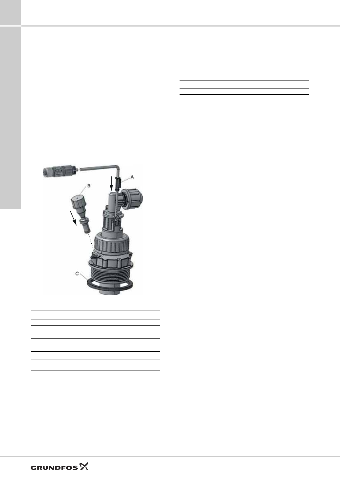
8
A
B
C
Accessories for dosing pumps
Accessories for small dosing pumps up to 60 l/h
Emission protection kits
Gas emitted by liquid in a container can cause bad
odour and corrosion. Emission protection kits help
avoid such problems. Rigid suction lances can be
retrofitted with emission protection kits.
Two variants are available:
• Emission protection kit with snifting valve: no gas
can escape from the container, but air can be drawn
in.
• Emission protection kit for use with filter: gas can
escape from the container and air can be drawn in.
The kit can be connected to a filter by means of a
4/6 mm hose.
Emission protection kits include:
• Gasket for the tank adapter
• Snifting valve or hose nipple 4/6 mm (hose is not
included)
• Gasket for the cable outlet.
M 12-plug-to-flat-plug adapter
The adapter allows to connect rigid suction lances or
foot valves with level indication to pumps with a level
input designed for flat plugs (e.g. DMX and DMH with
AR control unit).
Order data
Description Product number
M 12-plug-to-flat-plug adapter 96635010
Fig. 35 Emission protection kit
Position Description
A Gasket for the cable outlet
B Air valve
C Gasket for the tank adapter
Order data
Variant Product number
Emission protection kit with snifting valve 98071178
Emission protection kit for use with filter 98071179
TM06 8372 0317
42
Page 43

Accessories for dosing pumps
G 1/2
L 2
L 1
G 1/2
L 1
L 2
G 1/2
L 1
L 2
8
Injection units
Injection units connect the dosing line with the process
line. They ensure a minimum counterpressure of 0.7
bar and avoid backflow of the dosing liquid.
In general, they include:
• Injection pipe. PP, PVC and PVDF versions can be
shortened.
• Spring-loaded non-return valve with Tantal spring.
• Hose connection set: 4/6 mm, 6/9 mm, 6/12 mm,
and 9/12 mm.
• Pipe connection set: threaded, Rp 1/4", internal
thread (stainless steel).
Technical data
Max. flow rate
[l/h]
60
Max. pressure
[bar]
16
100 Stainless steel PTFE Stainless steel 27 50 95730936
16 PVC
Body Gasket Ball
PP
PVC
PVDF
Material Dimensions
FKM Ceramic 100 47 95730904
EPDM Ceramic 100 47 95730908
FKM Ceramic 100 47 95730912
EPDM Ceramic 100 47 95730916
PTFE Ceramic 100 47 95730920
FKM Ceramic 100 47 95730924
EPDM Ceramic 100 47 95730928
PTFE Ceramic 100 47 95730932
FKM Ceramic 300 47 95730940
EPDM Ceramic 300 47 95730944
PTFE Ceramic 300 47 95730948
Standard injection units
Dimensions
Fig. 36 Standard injection unit, PP, PVC, and PVDF
version
Fig. 37 Standard injection unit, stainless-steel version
L 1
[mm]
L 2
[mm]
Product number
TM04 8280 0411TM04 8281 0411
Accessories for small dosing pumps up to 60 l/h
Injection units with lip valve
Dimensions
Injection units with lip valve are typically used to add
sodium hypochlorite solution to water with a high
carbonate content. The FKM lip prevents
crystallisation and blocking caused by alkali carbonate
reactions at the point of injection.
Fig. 38 Injection unit with lip valve
Technical data
Max. flow rate
[l/h]
60 16 PVC FKM Ceramic 55 59 95730964
Max. pressure
[bar]
Body Gasket Ball
Material Dimensions
L 1
[mm]
L 2
[mm]
TM04 8282 0411
Product number
43
Page 44

8
L 1
L 2
G 1/2
L 1
G 1/2
L 2
L 1L 2
G 1/2
Accessories for dosing pumps
Accessories for small dosing pumps up to 60 l/h
Injection units with ball valve
Injection units with ball valve are used for applications
where the injection point must be closable. The ball
valve is placed between the injection pipe and the
spring-loaded non-return valve. Thus, the dosing line
can be completely disconnected from the process. The
non-return valve can be disassembled and cleaned
without stopping the process and emptying the
process line.
Technical data
Max. flow rate
[l/h]
60
Max. pressure
[bar]
16 PVC
64 Stainless steel PTFE Stainless steel 27 138 95730960
Body Gasket Ball
Material Dimensions
FKM Ceramic 100 183 95730952
EPDM Ceramic 100 183 95730956
Injection units with removable injection pipe
Injection units with removable injection pipe are used
where regular cleaning of the injection pipe is required.
The injection pipe can be removed from the process
line without stopping the process water flow. The
injection point can be closed with the integrated ball
valve. The immersion depth of the injection pipe can
be adjusted.
Dimensions
Fig. 39 Injection unit with ball valve
L 1
[mm]
L 2
[mm]
Product number
Dimensions
Fig. 40 Injection unit with removable injection pipe
TM04 8284 0411
TM04 8285 0411
Technical data
Max. flow rate
[l/h]
60 10 PVC
Max. pressure
[bar]
Body Gasket Ball
Material Dimensions
FKM Ceramic 185 280 95730968
EPDM Ceramic 185 280 95730972
Hot-injection units with ball valve
Hot-injection units with ball valve can be used for direct
injection of the dosing medium into processes with a
high process water temperature of up to 120 °C.
Hot-injection units have a stainless-steel injection pipe
and a bendable stainless-steel cooling pipe of 1 metre.
The stainless-steel ball valve is installed between the
injection pipe and the cooling pipe. The cooling pipe
separates the hot parts from the non-return valve and
the dosing line.
Technical data
Max. flow rate
[l/h]
60
Max. pressure
[bar]
16 PVDF PTFE Ceramic 27 1158 95730976
64 Stainless steel PTFE Stainless steel 27 1158 95730980
Body Gasket Ball
Material Dimensions
L 1
[mm]
L 2
[mm]
Dimensions
Fig. 41 Hot-injection unit with ball valve
L 1
[mm]
L 2
[mm]
Product number
TM04 8286 0411
Product number
44
Page 45
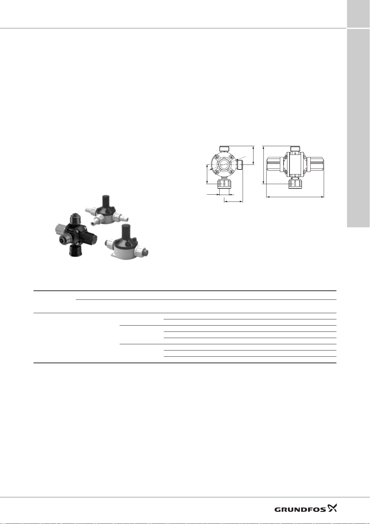
Accessories for dosing pumps
92
139
45
47
45
G 5/8
Ø 60
8
Multi-function valves, pressure relief valves, pressure loading valves
Multi-function valves combine the functions of
pressure relief valves and pressure loading valves. In
addition, they allow deaeration of the pump and
emptying of the outlet line for maintenance.
Pressure relief valves protect the pump and the
outlet-side installations against excessive pressure. All
pressurised dosing installations should include a
pressure relief valve.
Pressure loading valves maintain a certain
counterpressure for the dosing pump.
They are used in the following applications:
• too low counterpressure or no counterpressure at all
• fluctuating system pressure with outlet-side
pulsation damper.
• To prevent syphoning, when the inlet pressure is
higher than the counterpressure.
Multi-function valves
A multi-function valve is mounted directly on the pump
outlet side. The top connection is for the outlet line, the
side connection leads the relief liquid back into the
tank.
• Loading pressure, adjustable from 1 to 4 bar, is
factory-set to 3 bar.
• Relief pressure, adjustable from 7 to 16 bar, is
factory-set to 10 bar or 16 bar.
• Maximum operating pressure: 16 bar.
• Hose connection set: 4/6 mm, 6/9 mm, 6/12 mm,
and 9/12 mm.
Dimensions
Accessories for small dosing pumps up to 60 l/h
TM04 8288 0411
Fig. 43 Multi-function valve
Fig. 42 Multi-function valve, pressure relief valve,
pressure loading valve
Technical data
Max. flow rate
[l/h]
60 PVDF
Body Connections Gasket Diaphragm
PP
PVC
PVDF
TM04 8287 0411
Material Product number
Relief pressure
10 bar
FKM PTFE 95704585 95730821
EPDM PTFE 95704591 95730822
FKM PTFE 95730807 95730823
EPDM PTFE 95730808 95730824
PTFE PTFE 95730809 95730825
FKM PTFE 95730810 95730826
EPDM PTFE 95730811 95730827
PTFE PTFE 95730812 95730828
Relief pressure
16 bar
45
Page 46
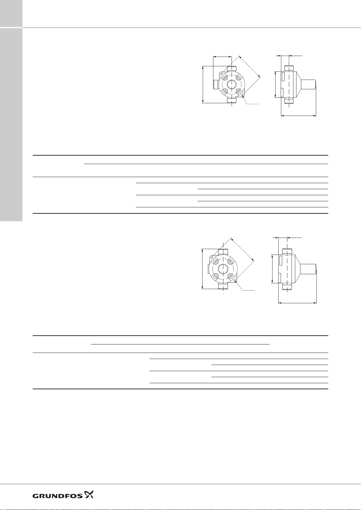
8
Ø4.5(-)
48(20)
96(40)
78 (-)
21(22)
82(82)
68(68)
21 (22)
68 (68)
82 (82)
Ø4.5 (-)
78 (-)
96 (40)
Accessories for dosing pumps
Accessories for small dosing pumps up to 60 l/h
Pressure relief valves PRV
Pressure relief valves are installed in the outlet line
near the pump using the 2 in-line connections. The
side connection leads the relief liquid back into the
tank.
• Relief pressure, adjustable from 5 to 10 bar, is
factory-set to 10 bar, or
• Relief pressure, adjustable from 7 to 16 bar, is
factory-set to 16 bar.
• Maximum operating pressure: 16 bar.
• Hose connection set: 4/6 mm, 6/9 mm, 6/12 mm,
and 9/12 mm.
• Pipe connection set: threaded, Rp 1/4", internal
thread (stainless steel).
Technical data
Max. flow rate
[l/h]
60 PTFE
Diaphragm Body and connections Gasket
Material Product number
Stainless steel No gaskets 95730771 95730783
Dimensions
Fig. 44 Pressure relief valve. Dimensions in brackets
PP FKM / EPDM 95730757 95730773
PVC
PVDF
apply to stainless-steel version.
Relief pressure
10 bar
FKM / EPDM 95730758 95730774
PTFE 95730759 95730775
FKM / EPDM 95730760 95730776
PTFE 95730761 95730777
Relief pressure
16 bar
TM04 8290 0411
Pressure loading valves PLV
Pressure loading valves are installed in the outlet line
after the pressure relief valve, and after the pulsation
damper, if fitted.
• Loading pressure, adjustable from 1 to 5 bar, is
factory-set to 3 bar.
• Maximum operating pressure: 16 bar.
• Hose connection set: 4/6 mm, 6/9 mm, 6/12 mm,
and 9/12 mm.
• Pipe connection set: threaded, Rp 1/4", internal
thread (stainless steel).
Technical data
Max. flow rate
[l/h]
60 PTFE
Diaphragm Body and connections Gasket
Dimensions
Fig. 45 Pressure loading valve. Dimensions in brackets
Material
PP FKM / EPDM 95730741
PVC
PVDF
Stainless steel No gaskets 95730751
apply to stainless-steel version.
Product number
FKM / EPDM 95730742
PTFE 95730743
FKM / EPDM 95730744
PTFE 95730745
TM04 8292 0411
46
Page 47
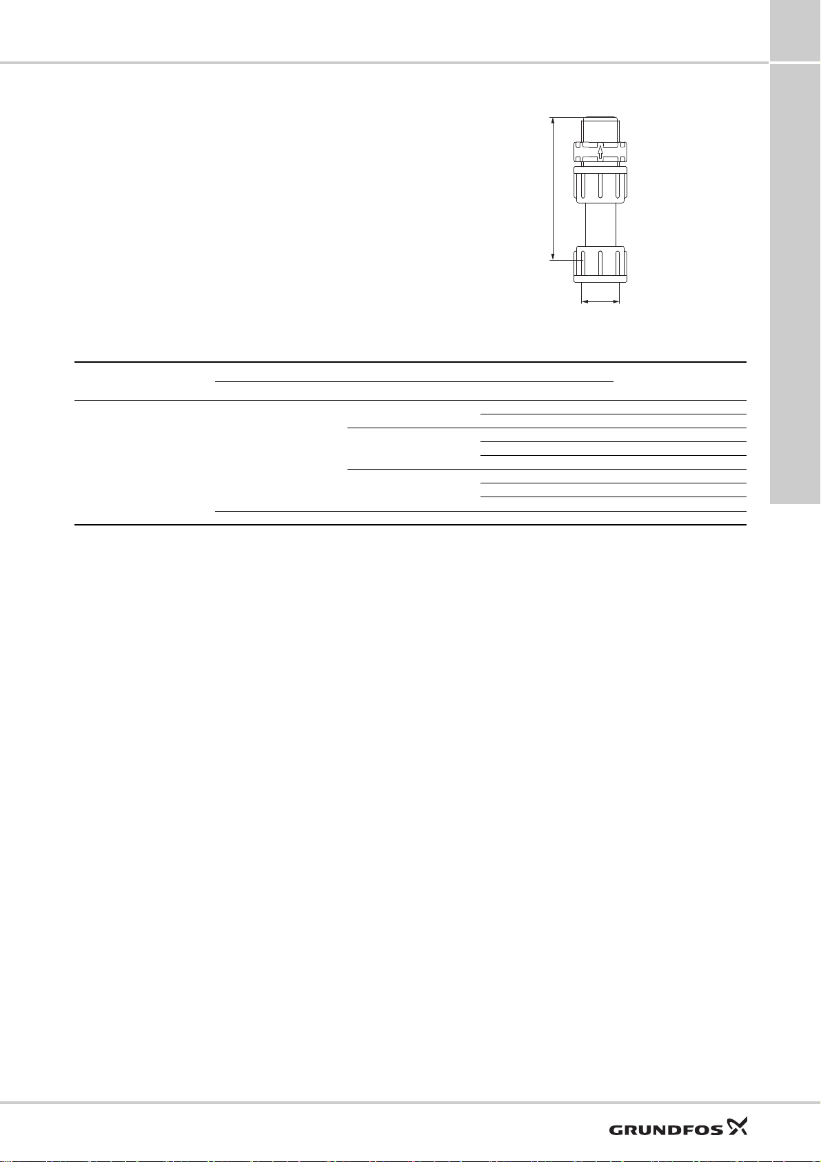
Accessories for dosing pumps
87
G 5/8
8
Pressure valves
Pressure valves provide a constant counterpressure of
3 bar. They are particularly required for DDA-FC or
DDA-FCM pumps at very small flow rates.
Pressure valves are installed either directly on the
pump outlet side, or on the pressure relief valve.
• Loading pressure: 3 bar, not adjustable.
• Maximum system pressure: 16 bar.
• Spring material: Alloy C-4 (NiMo16CrTi, material
number 2.4610).
• No connections included.
Technical data
Max. flow rate
[l/h]
60
Ball Body Gaskets
Ceramic
Stainless steel Stainless steel PTFE 95730333
Material
PP
PVC
PVDF
Dimensions
Fig. 46 Pressure valve
Product number
FKM 95730325
EPDM 95730326
FKM 95730327
EPDM 95730328
PTFE 95730329
FKM 95730330
EPDM 95730331
PTFE 95730332
TM04 8293 0411
Accessories for small dosing pumps up to 60 l/h
47
Page 48

8
Accessories for dosing pumps
Accessories for small dosing pumps up to 60 l/h
Pump connection kits and inlay kits
Retrofit pump connection kits and inlay kits for the
integration of Grundfos standard dosing pumps into
installations with various sizes of hoses or pipes.
A pump connection kit includes:
• 1 set of inlays
• 1 union nut.
Fig. 47 Left: pump connection kit; right: inlay kit
The inlay kits are used to connect pumps and
accessories to pipes or hoses that differ from Grundfos
standard sizes.
An inlay kit includes:
• 2 sets of inlays.
Technical data
Connection type Size Material
PP 97691902 -
4/6 mm, 6/9 mm, 6/12 mm, 9/12 mm
Hose (cone and ring)
0.17" x 1/4", 1/4" x 3/8", 3/8" x 1/2"
4/6 mm, or 0.17" x 1/4"
4/9 mm
5/8 mm
6/8 mm
Hose (cone and ring)
Hose (cutting ring type) 1/8" x 1/4"
Pipe welding External diameter 16 mm
Pipe cementing Internal diameter 12 mm PVC 97702491 95730726
Pipe, external thread 1/2" NPT
Pipe, internal thread
Pipe (cutting ring type)
6/9 mm
6/12 mm
9/12 mm
1/4" x 3/8
3/8" x 1/2"
Rp 1/4" Stainless steel 97702472 95730739
1/4" NPT Stainless steel 97702473 95730740
4/6 mm Stainless steel 97702506 -
8/10 mm Stainless steel 97702507 -
PVC 97691903 -
PVDF 97691904 -
PP 97691905 -
PVC 97691906 -
PVDF 97691907 -
PP 97702474 95730984
PVC 97702485 95730720
PVDF 97702495 95730729
PP 98153922 98153977
PVC 98153944 98154006
PVDF 98153949 98154029
PP 97702475 95730711
PVC 97702486 95730721
PVDF 97702496 95730730
PP 97702476 95730712
PVC 97702487 95730722
PVDF 97702497 95730731
PP 97702477 95730713
PVC 97702488 95730723
PVDF 97702498 95730732
PP 97702478 95730714
PVC 97702489 95730724
PVDF 97702499 95730733
PP 97702479 95730715
PVC 97702490 95730725
PVDF 97702500 95730734
PP 97702482 95730718
PVC 97702492 95730727
PVDF 97702503 95730737
PP 97702483 95730719
PVC 97702493 95730728
PVDF 97702504 95730738
PP 97702481 95730717
PVDF 97702502 95730736
PP 97702480 95730716
PVDF 97702501 95730735
PP 97702484 -
PVC 97702494 -
PVDF 97702505 -
Stainless steel 97702508 -
TM04 8294 0411
Product number
Connection kit Inlay kit
TM04 8295 0411
48
Page 49

Accessories for dosing pumps
Adapters
Threaded adapters
Threaded adapters are used to convert between
different threaded connection sizes.
Technical data
8
A threaded adapter kit includes:
• 1 adapter
• 1 O-ring.
Type
Threaded connection size Material
Internal thread External thread Body Gaskets
PP FKM / EPDM 95730407
FKM / EPDM 95730408
FKM / EPDM 95730410
FKM / EPDM 95730413
FKM / EPDM 95730415
FKM / EPDM 95730418
FKM / EPDM 95730420
FKM / EPDM 95730423
FKM / EPDM 95730425
FKM / EPDM 95730428
FKM / EPDM 95730430
G 3/8" G 5/8"
TM04 8296 0411
G 5/8" G 3/8"
TM04 8297 0411
G 5/8" G 3/4"
TM04 8298 0411
G 5/8" G 1 1/4"
TM04 8299 0411
G 5/8" M 20 x 1.5
TM04 8300 0411
PVC
PVDF
PP FKM / EPDM 95730412
PVC
PVDF
PP FKM / EPDM 95730417
PVC
PVDF
PP FKM / EPDM 95730422
PVC
PVDF
PP FKM / EPDM 95730427
PVC
PVDF
Product number
PTFE 95730409
PTFE 95730411
PTFE 95730414
PTFE 95730416
PTFE 95730419
PTFE 95730421
PTFE 95730424
PTFE 95730426
PTFE 95730429
PTFE 95730431
Accessories for small dosing pumps up to 60 l/h
G 5/8" M 30 x 3.5 PVDF
TM04 8475 0612
G 1 1/4" G 5/8"
TM04 8301 0411
Union nut adapters
Union nut adapters consist of a rigid pipe with union
nuts on both ends. They have neither gaskets nor
glued or welded connections.
Technical data
Type
TM04 8306 0411
Threaded connection size Material
Internal thread Internal thread Body
G 5/8" G 5/8"
FKM / EPDM 98154048
PTFE 98154054
PP FKM / EPDM 95730432
PVC
PVDF
FKM / EPDM 95730433
PTFE 95730434
FKM / EPDM 95730435
PTFE 95730436
Product number
PVC 95730437
PP 95730438
PVDF 95730439
49
Page 50
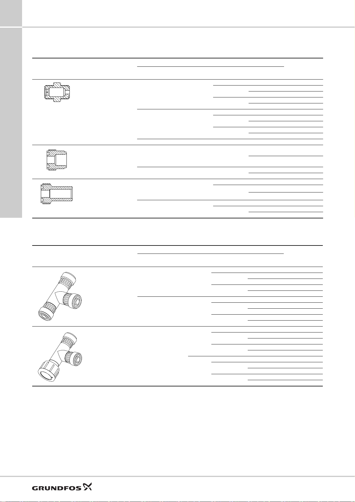
8
Accessories for dosing pumps
Accessories for small dosing pumps up to 60 l/h
Hose-to-hose and hose-to-pipe adapters
Technical data
Type Description
Valve body with two
external threads G 5/8"
TM04 8302 0411
Pipe cementing end on
one side, external thread
G 5/8" on the other side
TM04 8360 0711
Pipe welding end on one
side, external thread G
5/8" on the other side
TM04 8303 0411
Side 1 Side 2
For hoses 4/6 mm, 6/9 mm, 6/12 mm,
Without Threaded Rp 1/4 Stainless steel PTFE 95730361
For hoses 4/6 mm,
6/9 mm, 6/12 mm,
9/12 mm
Without Internal ∅12 mm PVC
For hoses 4/6 mm,
6/9 mm, 6/12 mm,
9/12 mm
Without External ∅16 mm
Connections Material
Body and
connections
PP FKM / EPDM 95730367
9/12 mm
Without
Internal ∅12 mm PVC
External ∅16 mm
PVC
PVDF
PP FKM / EPDM 95730356
PVC
PVDF
PP FKM / EPDM 95730377
PVDF
PP FKM / EPDM 95730362
PVDF
Gaskets
FKM / EPDM 95730368
PTFE 95730369
FKM / EPDM 95730370
PTFE 95730371
FKM / EPDM 95730357
PTFE 95730358
FKM / EPDM 95730359
PTFE 95730360
FKM / EPDM 95730378
PTFE 95730379
FKM / EPDM 95730365
PTFE 95730366
FKM / EPDM 95730380
PTFE 95730381
FKM / EPDM 95730363
PTFE 95730364
Product number
T-pieces
Technical data
Type Description
Three external
threads G 5/8"
TM04 8304 0411
Two male threads G
5/8", one internal
connection with union
nut
TM04 8305 0411
Connections Material
Bottom Top Side
For hoses 4/6 mm, 6/9 mm, 6/12 mm,
Union nut
G 5/8"
9/12 mm
- Without -
For hoses
4/6 mm,
6/9 mm,
6/12 mm,
Without
9/12 mm
Without
Body and
connections
PP FKM / EPDM 95730387
PVC
PVDF
PP FKM / EPDM 95730346
PVC
PVDF
PP FKM / EPDM 95730397
PVC
PVDF
PP FKM / EPDM 95730351
PVC
PVDF
Gaskets
FKM / EPDM 95730388
PTFE 95730389
FKM / EPDM 95730390
PTFE 95730391
FKM / EPDM 95730347
PTFE 95730348
FKM / EPDM 95730349
PTFE 95730350
FKM / EPDM 95730398
PTFE 95730399
FKM / EPDM 95730400
PTFE 95730401
FKM / EPDM 95730352
PTFE 95730353
FKM / EPDM 95730354
PTFE 95730355
Product number
50
Page 51

Accessories for dosing pumps
Ø152
540
670
500
500
98
98
98
137
192
M5
8
Dosing tanks
Square tank, 100 litres
The closed, square tank has a screw cap and a
mounting platform for one pump or two pumps in
parallel.
The pump mounting platform is higher than the screw
cap to protect pumps and connections when filling
chemicals into the tank.
• Tank material: MDPE
• Weight: 15 kg
• Wall thickness: 4 mm
• Liquid temperature: -20 °C to +45 °C.
SMART Digital S pumps can be fitted directly on the
mounting platform by means of brass inserts moulded
into the platform. For other pumps a bracket is
required.
The square tank is prepared for a G 3/4" drain valve.
When using a rigid suction lance in the tank, choose
the counter nut for fixing (see page 41).
Dimensions
Accessories for small dosing pumps up to 60 l/h
Fig. 48 Square tank
TM04 8308 0411
Fig. 49 Square tank, dimensions
Order data
Tank volume
[l]
100 96489271
TM04 8307 0411
Product number
51
Page 52

8
Ø160
Ø420
Ø160
Rp 3/4"
350
420
45
Accessories for dosing pumps
Accessories for small dosing pumps up to 60 l/h
Cylindrical tanks
Cylindrical tanks are available transparent or black.
They have a litre scale and a black screw cap.
• Tank material: LLDPE, UV-stabilised
• Liquid temperature: -20 °C to +45 °C.
All cylindrical tanks are prepared for a G 3/4" opening
for a drain valve, and have a screw plug (PE/EPDM).
The cylindrical tanks with volumes of 60, 100, 200, 300
and 500 litres include additionally:
• Threaded M 6 inserts for the assembly of a SMART
Digital S, a DDI, or a DMX model 221 dosing pump.
For other pumps a bracket is required.
• A G 2" opening for a rigid suction lance or a foot
valve, closed with a screw plug
• A flange for an electric stirrer with threaded inserts
• Threaded M 6 inserts at the bottom part for floor
mounting with a set of floor-mounting brackets (see
page 54).
Technical data
Tank volume
[l]
40 - 3.4 96688081 95701166
60
100
200
300
500
1000
Dimensions
Prepared for direct assembly of an electric stirrer
- 5.5 98148805 98149053
Yes 5.5 98150038 98150040
- 7.5 98149057 98149082
Yes 7.5 98150051 98150052
- 11.5 98149215 98149224
Yes 11.5 98150053 98150054
- 13 98149245 98149252
Yes 13 98150055 98150056
- 28 98149266 98149269
Yes 28 98150057 98150058
- 40 96688086 95706305
Yes, with reinforced beam 48 98173675 98173752
Fig. 50 Cylindrical tank, 60 litres
Weight
[kg]
Transparent Black
TM04 8468 0412
Product number
52
Fig. 51 Cylindrical tank, 40 litres
TM04 8310 0411
Page 53

Accessories for dosing pumps
O
O
O
O
*
0[
0[
0[
*
*
O
O
O
O
0[
0[
0[
*
0[
0[
0[
*
*
Rp 3/4"
Ø1080
1260
Ø160
1150
50
8
Accessories for small dosing pumps up to 60 l/h
Fig. 52 Cylindrical tank, 60 and 100 litres
Fig. 53 Cylindrical tank, 200 and 300 litres
TM04 8465 0412TM04 8466 0412
TM04 8467 0412TM04 8315 0411
Fig. 54 Cylindrical tank, 500 litres
Fig. 55 Cylindrical tank, 1000 litres
53
Page 54

8
Ø 270
Ø 140
Ø 70
283
120
Accessories for dosing pumps
Accessories for small dosing pumps up to 60 l/h
Collecting tray
The collecting tray is available in several sizes to suit
the respective dosing tank size. It collects chemicals
that might leak out of the tank, and protects the
environment.
• Material: PE
• Colour: transparent.
For tank size
[l]
60 80 500 x 545 96726831
100 120 500 x 700 96726832
200 210 770 x 595 98150059
300 400 770 x 960 96726834
500 500 860 x 980 95701272
1000 1000 1150 x 1080 96726836
Volume
[l]
Accessories for dosing tanks
Fig. 56 Collecting tray
Dimensions (diameter x height)
[mm]
TM04 8316 0411
Product number
TM04 8318 0411
Fig. 57 Dissolving hopper, dimensions Fig. 58 Handheld mixer
Technical data
Description Specifications Material Product number
Drain valve for installation in the threaded
sleeve of the dosing tank
Ventilation valve Spring-loaded, opening pressure 0.05 bar PVC / FKM / glass 96694401
Dissolving hopper for washing powders into
the dosing tank
Handheld mixer for use in dosing tanks
Set of floor-mounting brackets 4 floor-mounting brackets with fixing screws 98149921
Set of screws for mounting a pump on a
100-litre square tank
Set of screws for mounting a pump on a 60-,
100-, 200-, 300-, or a 500-litre cylindrical tank
Set of screws for mounting a pump on a
40-litre or a 1000-litre cylindrical tank
Dosing tank connection G 3/4" PVC 96689132
Dosing tank connection: DN 40 through-bolt;
water connection: G 5/4", with union nut and inlay for PVC
pipe (cementing diameter 25 mm)
Shaft length 1200 mm, length can be adapted to the
corresponding dosing tank, with DN 15 through-bolt for
connection at the dosing tank
For pump types DDA, DDC, DDE Stainless steel 95730862
For pump types DDA, DDC, DDE, DDI, DMX model 221 Stainless steel 98159495
For pump types DDA, DDC, DDE, DDI, DMX model 221 PP 95730864
PVC 96726979
PE 98133793
TM04 8477 0512
54
Page 55
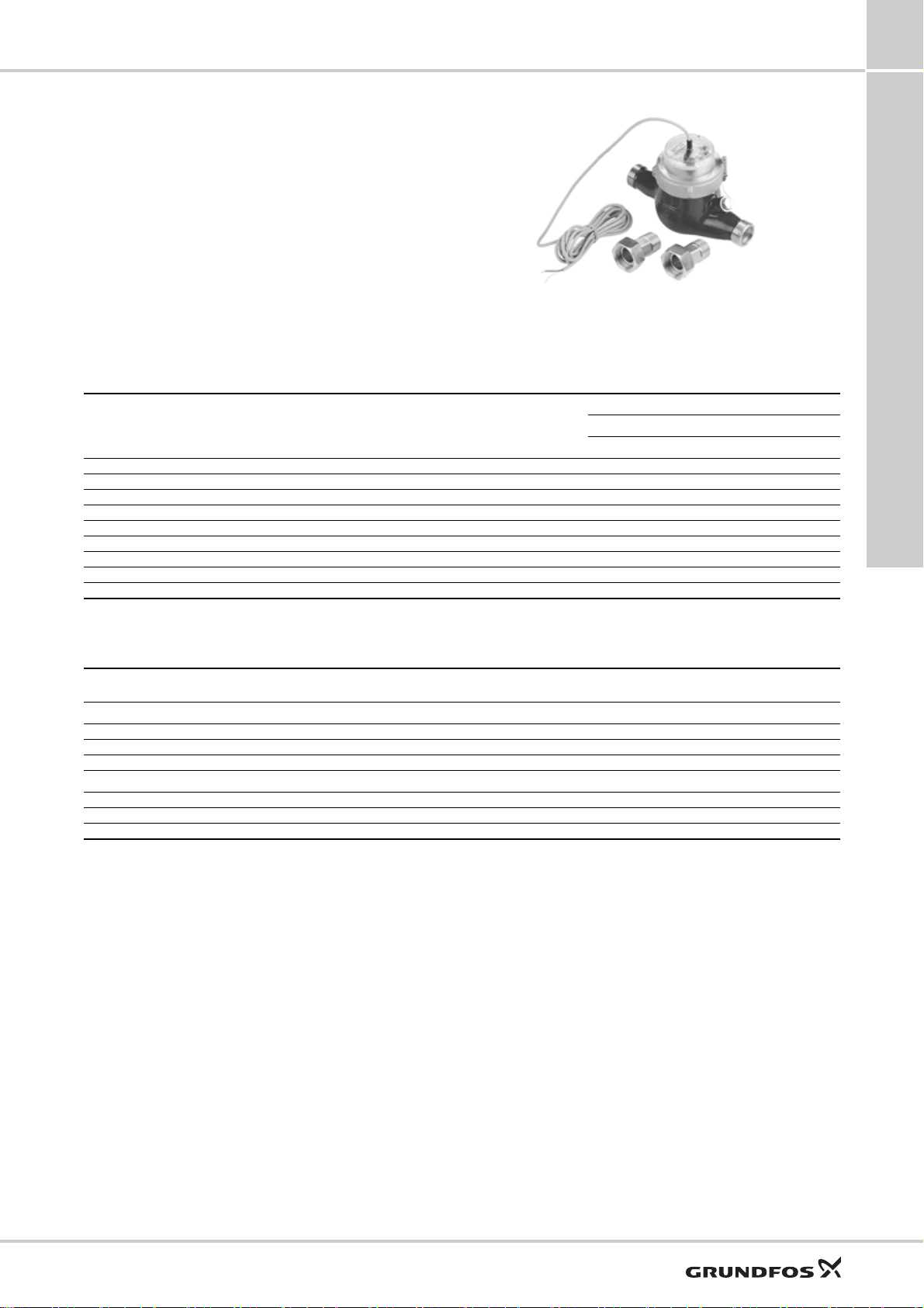
Accessories for dosing pumps
Wat er m et e r
The in-line water meter with potential-free pulse signal
is suitable for use in flow-proportional dosing
applications.
• Qn 1.5 and Qn 2.5 meters are of the multi-jet, dry
dial type, for cold water up to 30 °C, or hot water up
to 90 °C.
• Qn 15 meters and up are of the helical vane type,
for cold water up to 50 °C, or hot water up to 120 °C.
• Max. pressure: 16 bar.
If the water meter is connected directly to the pump
pulse input, use a control plug (PN 96698715).
• Qn 1.5 to Qn 15 meters are threaded.
• Qn 40 to Qn 150 meters are flanged.
• Cable length: 3 m.
8
TM04 8317 0411
Fig. 59 Water meter
Qn
[m
1.5* 1 3 16 120 50 96446846 - 96446897 -
2.5* 2.5 5 16 200 70 96446847 - 96446898 15* 10 30 16 3000 450 - 96446848 - 96446899
1.5* 0.25 3 16 120 50 96482640 - 96482643 -
2.5* 0.25 5 16 200 70 96482641 - 96482644 15* 2.5 30 16 3000 450 96482642 - 96482645 -
40** 100 80 10 4000 700 - 96446849 - 96446900
60** 25 120 10 6000 1200 - 96446850 - 96446901
150** 100 300 10 12000 3000 - 96446851 - 96446902
* Maximum load, Reed contact: 30 VAC/VDC, 0.2 A.
** Maximum load, Namur contact: 8-12 VDC, 1 kOhm (requires external power supply).
Pulse rate
3
/h]
[l/pulse]
Maximum
short-period
capacity
3
/h]
[m
Maximum
pressure
[bar]
Transitional
capacity with
error ± 2 %
[l/h]
Minimum
capacity with
error ± 5 %
[l/h]
30 °C 50 °C 90 °C 120 °C
Product number
Maximum water temperature
Dimensions
Size Connections Installation kit connection
Threaded connection
Qn 1.5 G 3/4" G 1/2" 165 245
Qn 2.5 G 1" G 3/4" 190 288
Qn 15 G 2.5 G 2" 300 438
Flanged connection
Qn 40 DN 80 225 Qn 60 DN 100 250 -
Qn 150 DN 150 300 -
Port-to-port length
[mm]
Port-to-port length incl. kit
[mm]
Accessories for small dosing pumps up to 60 l/h
55
Page 56
9
Pumped liquids
9. Pumped liquids
SMART Digital S
The resistance table below is intended as a general
guide for material resistance (at room temperature),
and does not replace testing of the chemicals and
pump materials under specific working conditions.
Pumped liquid (20 °C)
Description
Acetic acid CH3COOH
Aluminium chloride AlCl
Aluminium sulphate Al
Ammonia, aqueous NH
Calcium hydroxide ★
Calcium hypochlorite Ca(OCl)
Chromic acid H
Copper sulphate CuSO
Ferric chloride ★
Ferric sulphate ★
Ferrous chloride FeCl
Ferrous sulphate FeSO
Fluosilicic acid H
Hydrochloric acid HCl
Hydrogen peroxide H
Nitric acid HNO
Peracetic acid CH
Potassium hydroxide KOH 50
Potassium permanganate KMnO
Sodium chlorate NaClO
Sodium chloride NaCl 30
Sodium chlorite NaClO
Sodium hydroxide NaOH
Sodium hypochlorite NaClO 12-15 -
Sodium sulphide Na
Sodium sulphite Na
Sodium thiosulfate Na
Sulphurous acid H
Sulphuric acid ★
● Resistant
❍ Limited resistance
- Not resistant
7
3
3
4
Chemical
formula
(SO4)
2
OH 28
4
Ca(OH)
CrO
2
FeCl
Fe2(SO4)
SiF
2
2O2
COOOH 5-15
3
2
2SO3
2S2O3
2SO3
H2SO
3
★
Risk of crystallisation.
4
★
Reacts violently with water and generates much heat.
(Pump should be absolutely dry before dosing sulphuric acid.)
★7Once the pump is stopped, calcium hydroxide will sediment rapidly.
Concentration
%
25
60
85
3
3
2
2
4
4
3
3
2
4
6
3
4
3
2
S30
4
40
60
20
10
30 -
50 -
30
60
60
40
50
40
< 25
25-37
30
30
40
70 -
10
30
20
30
50
20
10
6
< 80
80-96
98 -
Further information:
http://product-selection.grundfos.com/liquids.html
The data shown are based on information from various
sources available, but many factors (purity,
temperature, abrasive particles, etc.) may affect the
chemical resistance of a given material.
Note: Some of the liquids in this table may be toxic,
corrosive or hazardous. Please be careful when
handling these liquids.
Material
Dosing head Gasket Ball
PE
PP
PVDF
SS 1.4401
PVC
FKM
EPDM
PTFE
●●●●
●●●●
●●❍
●●
●●●●●●●●●
●
●●●●●●●●●
❍●
●●●●●●●●●
●●●●●●●●●
●●
●●❍●●●●●●
●●
●●●●●●●●●
●●❍●
●●
●●
●●●●●●●●●
●●●●●●●●●
❍● ● ● ●
❍●❍❍
●
●●●●❍●●●●
●●●●●●●●●
●●
●●
●●●●❍●●●●
●●●●
●●●●●●●●●
●●●●●●●●●
●●●●●●●●●
●●●●●●●●●
●●
❍●
-
-
●●
-
-
●
-
●
-
-
-
-
●●
-
●●
-
-
-
●
-
-
●●
❍●●●●●
-
●●●●
-
●●●●
---
●●●●●●
-
●●●●●●
●●❍●● ●
●●
●●●●●●
●●●●●●
-
●●●●●●
●●❍●● ●
-
●
--
-
●●●●●●
-
●●●●●●
●●❍●● ●
●●
-
❍
●●
●●●●
-
●●●
❍● ● ●
-
●●●
-
●●❍
●●❍
●●●●
●●●●
-
●●
-
●●
Ceramic
(Accessories)
-
-
-
56
Page 57

SMART Digital S
10. Grundfos Product Center
Online search and sizing tool to help you
make the right choice.
http://product-selection.grundfos.com
10
Grundfos Product Center
SIZING enables you to
size a pump based on
entered data and
selection choices.
REPLACEMENT enables you to find a
replacement product.
Search results will include information on
• the lowest purchase price
• the lowest energy consumption
• the lowest total life cycle cost.
CATALOGUE gives you
access to the Grundfos
product catalogue.
LIQUIDS enables you to find pumps
designed for aggressive, flammable
or other special liquids.
All the information you need in one place Downloads
Performance curves, technical specifications, pictures, dimensional drawings, motor
curves, wiring diagrams, spare parts, service kits, 3D drawings, documents, system parts.
The Product Center displays any recent and saved items - including complete projects right on the main page.
On the product pages, you can download
installation and operating instructions, data
booklets, service instructions, etc. in PDF format.
Subject to alterations.
57
Page 58

95724709
ECM: 1207283
0517
GRUNDFOS A/S
DK-8850 Bjerringbro . Denmark
Telephone: +45 87 50 14 00
www.grundfos.com
The name Grundfos, the Grundfos logo, and be think innovate are registered trademarks owned by Grundfos Holding A/S or Grundfos A/S, Denmark. All rights reserved worldwide. © Copyright Grundfos Holding A/S
 Loading...