

Page 1

CUE, 110-250 kW
Installation and operating instructions
GRUNDFOS INSTRUCTIONS
Page 2

English (GB)
2
English (GB) Installation and operating instructions
Original installation and operating instructions
CONTENTS
Page
1. Symbols used in this document
2. Introduction
This manual introduces all aspects of your Grundfos CUE
frequency converter in the power range of 110 to 250 kW.
Always keep this manual close to the CUE.
2.1 General description
CUE is a series of external frequency converters especially
designed for pumps.
Thanks to the startup guide in the CUE, the installer can quickly
set central parameters and put the CUE into operation.
Connected to a sensor or an external control signal, the CUE will
quickly adapt the pump speed to the actual demand.
2.2 Applications
The CUE series and Grundfos standard pumps are a supplement
to the Grundfos E-pumps range with integrated frequency
converter.
A CUE solution offers the same E-pump functionality in these
cases:
• in mains voltage or power ranges not covered by the E-pump
range
• in applications where an integrated frequency converter is not
desirable or permissible.
1. Symbols used in this document
2
2. Introduction
2
2.1 General description
2
2.2 Applications
2
2.3 References
3
3. Safety and warnings
3
3.1 Warning
3
3.2 Safety regulations
3
3.3 Installation requirements
3
3.4 Reduced performance under certain conditions
3
4. Identification
4
4.1 Nameplate
4
4.2 Packaging label
4
5. Mechanical installation
4
5.1 Receipt and storage
4
5.2 Transportation and unpacking
4
5.3 Space requirements and air circulation
5
5.4 Mounting
5
6. Electrical connection
7
6.1 Electrical protection
7
6.2 Mains and motor connection
7
6.3 Connecting the signal terminals
8
6.4 Connecting the signal relays
11
6.5 Connecting the MCB 114 sensor input module
11
6.6 EMC-correct installation
12
6.7 RFI filters
12
6.8 Output filters
13
7. Operating modes
14
8. Control modes
14
8.1 Uncontrolled operation (open loop)
14
8.2 Controlled operation (closed loop)
14
9. Menu overview
15
10. Setting by means of the control panel
17
10.1 Control panel
17
10.2 Back to factory settings
18
10.3 CUE settings
18
10.4 Startup guide
18
10.5 GENERAL
23
10.6 OPERATION
24
10.7 STATUS
25
10.8 INSTALLATION
27
11. Setting by means of PC Tool E-products
35
12. Priority of settings
35
12.1 Control without bus signal, local operating mode
35
12.2 Control with bus signal, remote-controlled operating
mode
35
13. External contro l sig nals
36
13.1 Digital inputs
36
13.2 External setpoint
36
13.3 GENIbus signal
37
13.4 Other bus standards
37
14. Maintenance and service
37
14.1 Cleaning the CUE
37
14.2 Service parts and service kits
37
15. Fault finding
37
15.1 Warning and alarm list
37
15.2 Resetting of alarms
38
15.3 Indicator lights
38
15.4 Signal relays
38
16. Technical data
39
16.1 Enclosure
39
16.2 Main dimensions and weights
39
16.3 Surroundings
40
16.4 Terminal torques
40
16.5 Cable length
40
16.6 Fuses and cable cross-section
40
16.7 Inputs and outputs
41
16.8 Sound pressure level
41
17. Disposal
41
Warning
Prior to installation, read these installation and
operating instructions. Installation and operation
must comply with local regulations and accepted
codes of good practice.
Warning
If these safety instructions are not observed, it may
result in personal injury.
Caution
If these safety instructions are not observed, it may
result in malfunction or damage to the equipment.
Note
Notes or instructions that make the job easier and
ensure safe operation.
Caution
If the pump speed exceeds the rated speed, the
pump will be overloaded.
Page 3

English (GB)
3
2.3 References
Technical documentation for Grundfos CUE:
• The manual contains all information required for putting the
CUE into operation.
• The data booklet contains all technical information about the
construction and applications of the CUE.
• The service instructions contain all required instructions for
dismantling and repairing the frequency converter.
Technical documentation is available on www.grundfos.com >
Grundfos Product Center.
If you have any questions, please contact the nearest Grundfos
company or service workshop.
3. Safety and warnings
3.1 Warning
Wait only for shorter time if stated so on the nameplate of the
CUE in question.
3.2 Safety regulations
• The on/off button of the control panel does not disconnect the
CUE from the power supply and must therefore not be used as
a safety switch.
• The CUE must be earthed correctly and protected against
indirect contact according to local regulations.
• The leakage current to earth exceeds 3.5 mA.
• Enclosure class IP20/21 must not be installed freely
accessible, but only in a panel.
• Enclosure class IP54/55 must not be installed outdoors
without additional protection against weather conditions and
the sun.
• Always observe local regulations as to cable cross-section,
short-circuit protection and overcurrent protection.
3.3 Installation requirements
The general safety necessitates special considerations as to
these aspects:
• fuses and switches for overcurrent and short-circuit protection
• selection of cables (mains current, motor, load distribution and
relay)
• net configuration (IT, TN, earthing)
• safety on connecting inputs and outputs (PELV).
3.3.1 IT mains
In connection with IT mains and earthed delta mains, the mains
voltage may exceed 440 V between phase and earth.
3.3.2 Aggressive en viro nmen t
The CUE contains a large number of mechanical and electronic
components. They are all vulnerable to environmental impact.
3.4 Reduced performance under certain conditions
The CUE will reduce its performance under these conditions:
• low air pressure (at high altitude)
• long motor cables.
The required measures are described in the next two sections.
3.4.1 Reduction at low air pressure
PELV = Protective Extra Low Voltage.
At low air pressure, the cooling capacity of air is reduced, and the
CUE automatically reduces the performance to prevent overload.
It may be necessary to select a CUE with a higher performance.
3.4.2 Reduction in connection with long motor cables
The maximum cable length for the CUE is 300 m for unscreened
and 80 m for screened cables. In case of longer cables, contact
Grundfos.
The CUE is designed for a motor cable with a maximum crosssection as stated in section 16.6 Fuses and cable cross-section.
Warning
Any installation, maintenance and inspection must be
carried out by trained personnel.
Warning
Touching the electrical parts may be fatal, even after
the CUE has been switched off.
Before performing any work on the CUE, the mains
supply and other input voltages must be switched off
for a minimum time of 20 minutes.
Warning
Do not connect 380-500 V CUE frequency converters
to mains supplies with a voltage between phase and
earth of more than 440 V.
Caution
The CUE should not be installed in an environment
where the air contains liquids, particles or gases
which may affect and damage the electronic
components.
Warning
At altitudes above 2000 m, the PELV requirements
cannot be met.
Page 4

English (GB)
4
4. Identification
4.1 Nameplate
The CUE can be identified by means of the nameplate. An
example is shown below.
Fig. 1 Example of nameplate
4.2 Packaging label
The CUE can also be identified by means of the label on the
packaging.
5. Mechanical installation
The individual CUE cabinet sizes are characterised by their
enclosures. The table in section 16.1 Enclosure shows the
relationship between enclosure class and enclosure type.
5.1 Receipt and storage
Check on receipt that the packaging is intact, and the unit is
complete. In case of damage during transport, contact the
transport company to complain.
Note that the CUE is delivered in packaging which is not suitable
for outdoor storage.
5.2 Transportation and unpacking
To prevent damage during the transport to the site, the CUE must
only be unpacked at the installation site.
Remove the cardboard box, and keep the CUE on the pallet for
as long as possible.
The packaging contains accessory bag(s), documentation and
the unit itself.
5.2.1 Lifting the CUE
Always lift the CUE using the lifting holes. Use a bar to avoid
bending the lifting holes. See fig. 2.
Fig. 2 Recommended lifting method
TM04 3272 4808
Text Description
T/C:
CUE (product name)
202P1M2... (internal code)
Prod. no: Product number: 12345678
S/N:
Serial number: 123456G234
The last three digits indicate the production
date: 23 is the week, and 4 is the year 2004.
1.5 kW Typical shaft power on the motor
IN:
Supply voltage, frequency and maximum input
current
OUT:
Motor voltage, frequency and maximum output
current. The maximum output frequency
usually depends on the pump type.
CHASSIS/IP20 Enclosure class
Tamb. Maximum ambient temperature
T/C: CUE202P1M2T5E20H1BXCXXXSXXXXAXBXCXXXXDX
Prod. no: 12345678
S/N: 123456G234
IN: 3x380-500 V 50/60Hz 3.7A
OUT: 3x0-Vin 0-100Hz 4.1 A 2.8 kV
A
CHASSIS/IP20 Tamb. 45C/122F
IIIIIIIIIIIBAR CODEIIIIIIIIIII
MADE IN DENMARK
Listed 76X1 E134261 Ind. Contr. Eq.
See manual for prefuse
CAUTION:
SEE MANUAL / VOIR MANUEL
WARNING:
STORED CHARGE DO NOT TOUCH UNTIL
4 MIN AFTER DISCONNECTION
CHARGE RESIDUELLE, ATTENDRE
4 MIN APRES DECONNEXION
1.5 kW (400V)
TM03 9896 4607
Page 5

English (GB)
5
5.3 Space requirements and air circulation
CUE units can be mounted side by side, but as a sufficient air
circulation is required for cooling, these requirements must be
met:
• Sufficient free space above and below the CUE to allow airflow
and cable connection. See fig. 3.
• Ambient temperature up to 45 °C.
Fig. 3 Airflow direction and required space for cooling [mm]
Furthermore, there must be sufficient space in front of the CUE
for opening the door of the CUE. See fig. 4.
Fig. 4 Free space in front of the CUE [mm]
5.4 Mounting
5.4.1 Mounting on the wall
1. Mark the mounting holes on the wall using the drilling
template. See fig. 5.
2. Drill the holes. See fig. 5.
3. Fit the screws at the bottom, but leave loose. Lift the CUE up
on the screws. Move the CUE against the wall, and fit the
screws at the top. Tighten all four screws. See fig. 2.
Fig. 5 Drilling of holes in the wall
TM03 9898 4607TM05 9324 3713
Min. 225
Min. 225
Caution
The user is responsible for mounting the CUE
securely on a firm surface.
Note
See the main dimensions and weights in section
16.2 Main dimensions and weights.
TM03 8860 2607
b
a
a
b
Page 6

English (GB)
6
5.4.2 Mounting on the floor
By means of a pedestal (option), the CUE can also be mounted
on the floor.
1. Mark the mounting holes on the floor. See fig. 6.
2. Drill the holes.
3. Mount the pedestal on the floor.
4. Mount the CUE on the pedestal using the enclosed screws.
See fig. 7.
Fig. 6 Drilling template for pedestal
Fig. 7 CUE on a pedestal
Warning
The CUE is top-heavy and may fall over if the
pedestal is not anchored to the floor.
Caution
The user is responsible for mounting the CUE
securely on a firm surface.
Note
See the pedestal kit instructions for further
information.
TM05 9669 4313
Pos.
D1h
[mm]
D2h
[mm]
1 400 400
2 325 420
3 283.8 378.8
4 240 240
5 4 x 14 4 x 14
6 217 317
5
6
3
1
2
4
TM03 9895 4607
Page 7

English (GB)
7
6. Electrical connection
Fig. 8 Example of three-phase mains connection of the CUE
with mains switch, backup fuses and additional
protection
6.1 Electrical protection
6.1.1 Protection against electric shock, indirect contact
Protective conductors must always have a yellow/green (PE) or
yellow/green/blue (PEN) colour marking.
Instructions according to EN IEC 61800-5-1:
• The CUE must be stationary, installed permanently and
connected permanently to the mains supply.
• The earth connection must be carried out with duplicate
protective conductors.
6.1.2 Protection against short-circuit, fuses
The CUE and the supply system must be protected against shortcircuit.
Grundfos demands that the backup fuses mentioned in section
16.6 Fuses and cable cross-section are used for protection
against short-circuit.
The CUE offers complete short-circuit protection in case of a
short-circuit on the motor output.
6.1.3 Additional protection
If the CUE is connected to an electrical installation where an
earth leakage circuit breaker (ELCB) is used as additional
protection, the circuit breaker must be of a type marked with the
following symbols:
The circuit breaker is type B.
The total leakage current of all the electrical equipment in the
installation must be taken into account.
The leakage current of the CUE in normal operation can be seen
in section 16.7.1 Mains supply (L1, L2, L3).
During startup and in asymmetrical supply systems, the leakage
current can be higher than normal and may cause the ELCB to
trip.
6.1.4 Motor protection
The motor requires no external motor protection. The CUE
protects the motor against thermal overloading and blocking.
6.1.5 Protection against overcurrent
The CUE has an internal overcurrent protection for overload
protection on the motor output.
6.1.6 Protection against mains voltage transients
The CUE is protected against mains voltage transients according
to EN 61800-3, second environment.
6.2 Mains and motor connection
The supply voltage and frequency are marked on the CUE
nameplate. Make sure that the CUE is suitable for the power
supply of the installation site.
6.2.1 Mains switch
A mains switch can be installed before the CUE according to local
regulations. See fig. 8.
Warning
The owner or installer is responsible for ensuring
correct earthing and protection according to local
standards.
Warning
Before making any work on the CUE, the mains
supply and other voltage inputs must be switched off
for at least as long as stated in section 3. Safety and
warnings.
TM03 8525 1807
Warning
The CUE must be earthed correctly and protected
against indirect contact according to local
regulations.
Caution
The leakage current to earth exceeds 3.5 mA, and a
reinforced earth connection is required.
ELCB
Caution
The leakage current to earth exceeds 3.5 mA.
ELCB
Page 8
English (GB)
8
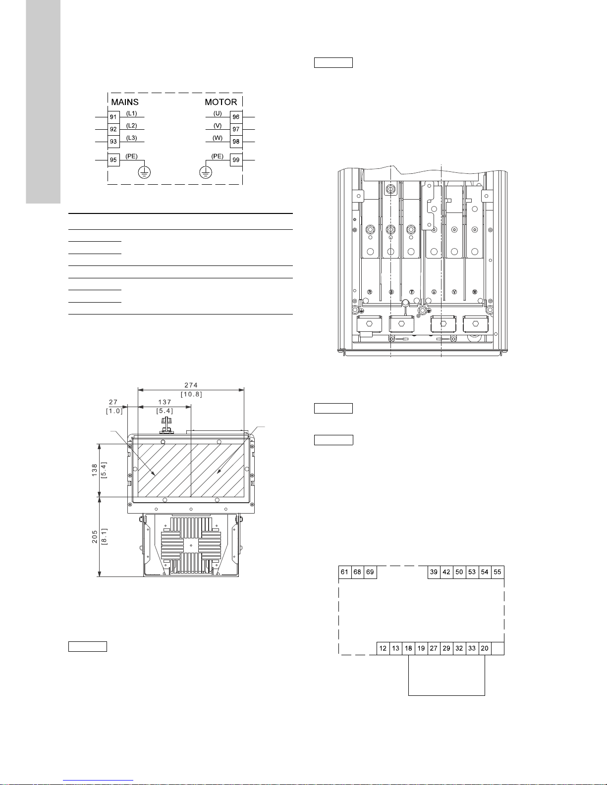
6.2.2 Wiring diagram
The wires in the terminal box must be as short as possible.
Excepted from this is the earth conductor which must be so long
that it is the last one to be disconnected in case the cable is
inadvertently pulled out of the cable entry.
Fig. 9 Wiring diagram, three-phase mains connection
6.2.3 Gland plate
Cables are connected through the gland plate from the bottom.
The gland plate must be fitted to the CUE to ensure the specified
protection degree as well as to ensure sufficient cooling.
Drill holes in the marked areas. See fig. 10.
Fig. 10 CUE viewed from the bottom [mm]
6.2.4 Motor connection
For information about enclosures, see table in section
16.1 Enclosure.
1. Connect the earth conductor to terminal 99 (PE). See fig. 11.
2. Connect the motor conductors to terminals 96 (U), 97 (V), 98
(W).
3. Fix the screened cable with a cable clamp.
6.2.5 Mains connecti on
1. Connect the earth conductor to terminal 95 (PE). See fig. 11.
2. Connect the mains conductors to terminals 91 (L1), 92 (L2),
93 (L3).
3. Fix the mains cable with a cable clamp.
6.2.6 Terminal location
Take the following terminal positions into consideration when you
design the cable connection. See fig. 11.
Fig. 11 Earth, mains and motor connection
6.3 Connecting the signal terminals
Connect the signal cables according to the guidelines for good
practice to ensure EMC-correct installation. See section
6.6 EMC-correct installation.
• Use screened signal cables with a conductor cross-section of
min. 0.5 mm
2
and max. 1.5 mm2.
• Use a 3-conductor screened bus cable in new systems.
6.3.1 Minimum connection, signal terminal
Operation is only possible when terminals 18 and 20 are
connected, for instance by means of an external on/off switch or a
short wire.
Fig. 12 Required minimum connection, signal terminal
TM03 8799 2507
Terminal Function
91 (L1)
Three-phase supply92 (L2)
93 (L3)
95/99 (PE) Earth connection
96 (U)
Three-phase motor connection, 0-100 % of
mains voltage
97 (V)
98 (W)
TM05 9326 3713
Caution
The motor cable must be screened for the CUE to
meet EMC requirements.
Caution
Check that the mains voltage and frequency
correspond to the values on the nameplate of the
CUE and the motor.
TM05 9329 3713
Caution
As a precaution, signal cables must be separated
from other groups by reinforced insulation in their
entire lengths.
Note
If no external on/off switch is connected, short-circuit
terminals 18 and 20 using a short wire.
TM03 9057 3207
Start/stop
GND
Page 9
English (GB)
9
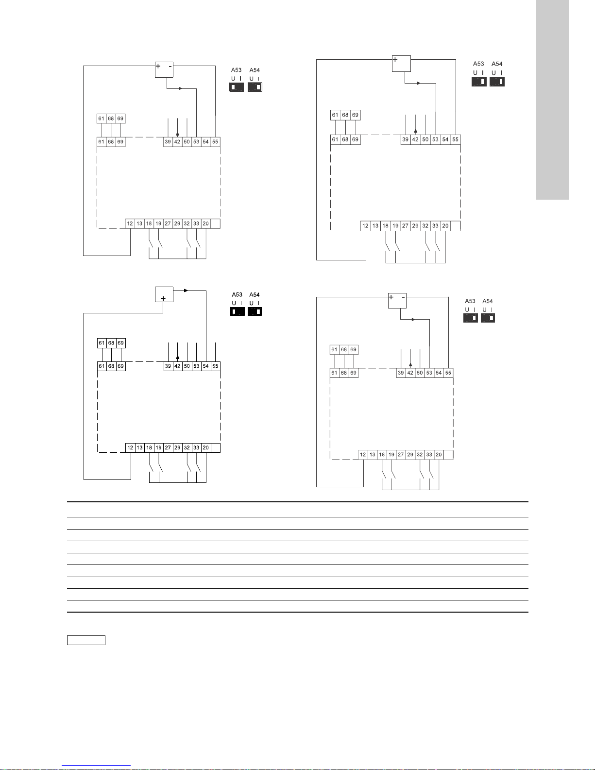
6.3.2 Wiring diagram, signal terminals
Terminals 27 and 29 are not used.
TM05 806 2811
TM05 808 2811
GND
RS-485 B
RS/485 A
RS-485 GND Y
AO 1
+10 V out
AI 1
AI 2
GND
+24 V out
+24 V out
DI 1
DI 2
DI 3
DI 4
GND
External setpoint,
voltage input
0-10 V
Te rm in a ls
U: 0-10 V
I: 0/4-20 mA
GND
AO 1
+10 V out
AI 1
AI
RS-485 GND Y
RS-485 A
RS-485 B
+24 V out
+24 V out
DI 1
DI 2
DI 3
DI 4
GND
GND
Two-wire sensor
0/4-20 mA
Te rm in a ls
U: 0-10 V
I: 0/4-20 mA
TM05 808 2811
TM05 805 2811
GND
AO 1
+10 V out
AI 1
AI 2
RS-485 GND Y
RS-485 A
RS-485 B
+24 V out
+24 V out
DI 1
DI 2
DI 3
DI 4
GND
GND
External setpoint,
current input
0/4-20 mA
Te rm in a ls
U: 0-10 V
I: 0/4-20 mA
GND
AO 1
+10 V out
AI 1
AI 2
RS-485 GND Y
RS-485 A
RS-485 B
GND
DI 4
DI 3
DI 2
DI 1
+24 V out
+24 V out
GND
Three-wire sensor
0/4-20 mA
Te rm in a ls
U: 0-10 V
I: 0/4-20 mA
Terminal Type Function Terminal Type Function
12 +24 V out Supply to sensor 42 AO 1 Analog output, 0-20 mA
13 +24 V out Additional supply 50 +10 V out Supply to potentiometer
18 DI 1 Digital input, start/stop 53 AI 1 External setpoint, 0-10 V, 0/4-20 mA
19 DI 2 Digital input, programmable 54 AI 2 Sensor input, sensor 1, 0/4-20 mA
20 GND Common frame for digital inputs 55 GND Common frame for analog inputs
32 DI 3 Digital input, programmable 61 RS-485 GND Y GENIbus, frame
33 DI 4 Digital input, programmable 68 RS-485 A GENIbus, signal A (+)
39 GND Frame for analog output 69 RS-485 B GENIbus, signal B (-)
Note
The RS-485 screen must be connected to frame.
Page 10
English (GB)
10
6.3.3 Connection of a thermistor (PTC) to the CUE
The connection of a thermistor (PTC) in a motor to the CUE
requires an external PTC relay.
The requirement is based on the fact that the thermistor in the
motor only has one layer of insulation to the windings. The
terminals in the CUE require two layers of insulation since they
are part of a PELV circuit.
A PELV circuit provides protection against electric shock. Special
connection requirements apply to this type of circuit. The
requirements are described in EN 61800-5-1.
In order to maintain PELV, all connections made to the control
terminals must be PELV. For example, the thermistor must have
reinforced or double insulation.
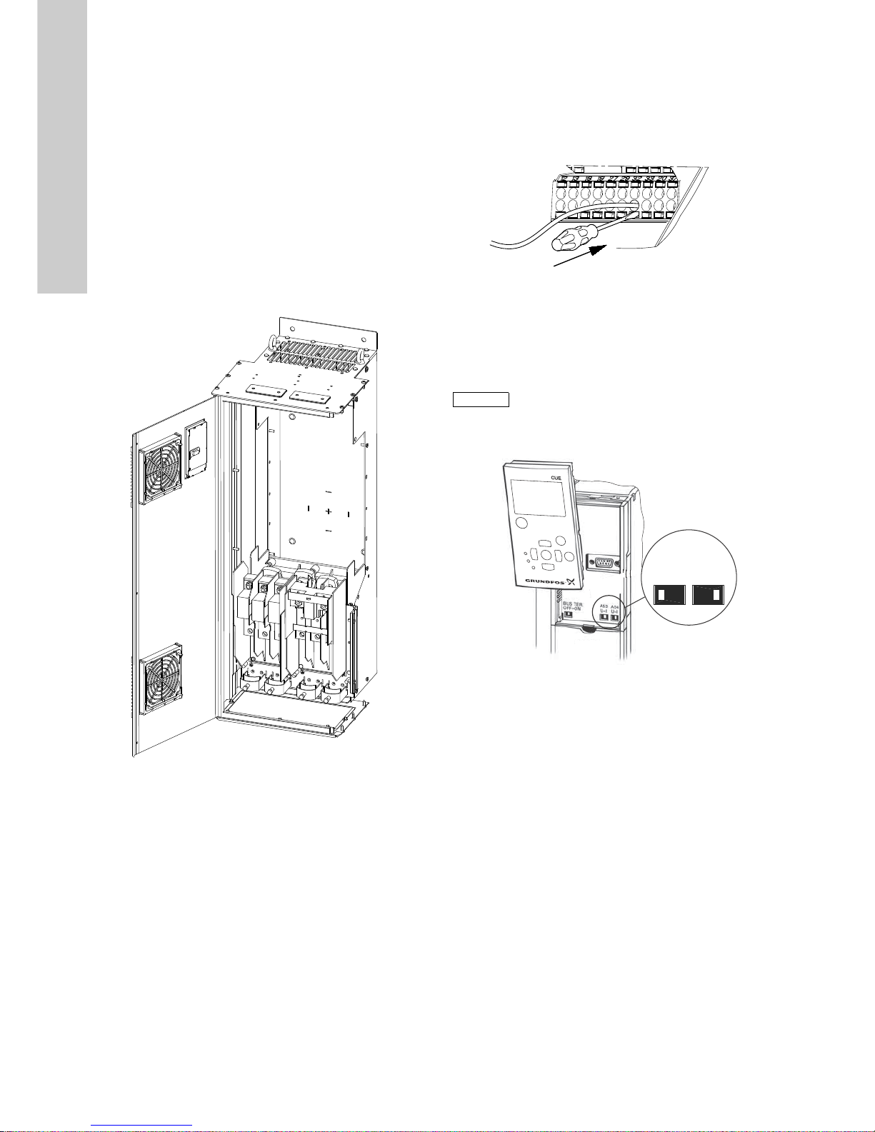
6.3.4 Access to signal terminals
All terminals for signal cables are located beneath the control
panel and can be accessed by opening the door of the CUE. See
fig. 13.
Fig. 13 Signal cable routing
6.3.5 Fitting the conductor
1. Remove the insulation at a length of 9 to 10 mm.
2. Insert a screwdriver with a tip of maximum 0.4 x 2.5 mm into
the square hole.
3. Insert the conductor into the corresponding round hole.
Remove the screwdriver. The conductor is now fixed in the
terminal.
Fig. 14 Fitting the conductor into the signal terminal
6.3.6 Setting the analog inputs, terminals 53 and 54
Contacts A53 and A54 are positioned behind the control panel
and used for setting the signal type of the two analog inputs.
The factory setting of the inputs is voltage signal "U".
Remove the control panel to set the contact. See fig. 15.
Fig. 15 Setting contact A54 to current signal "I"
TM05 9654 4213
TM03 9026 2807
Note
If a 0/4-20 mA sensor is connected to terminal 54,
the input must be set to current signal "I".
Switch off the power supply before setting contact
A54.
TM03 9104 3407
UI
A53
UI
A54
Page 11
English (GB)
11
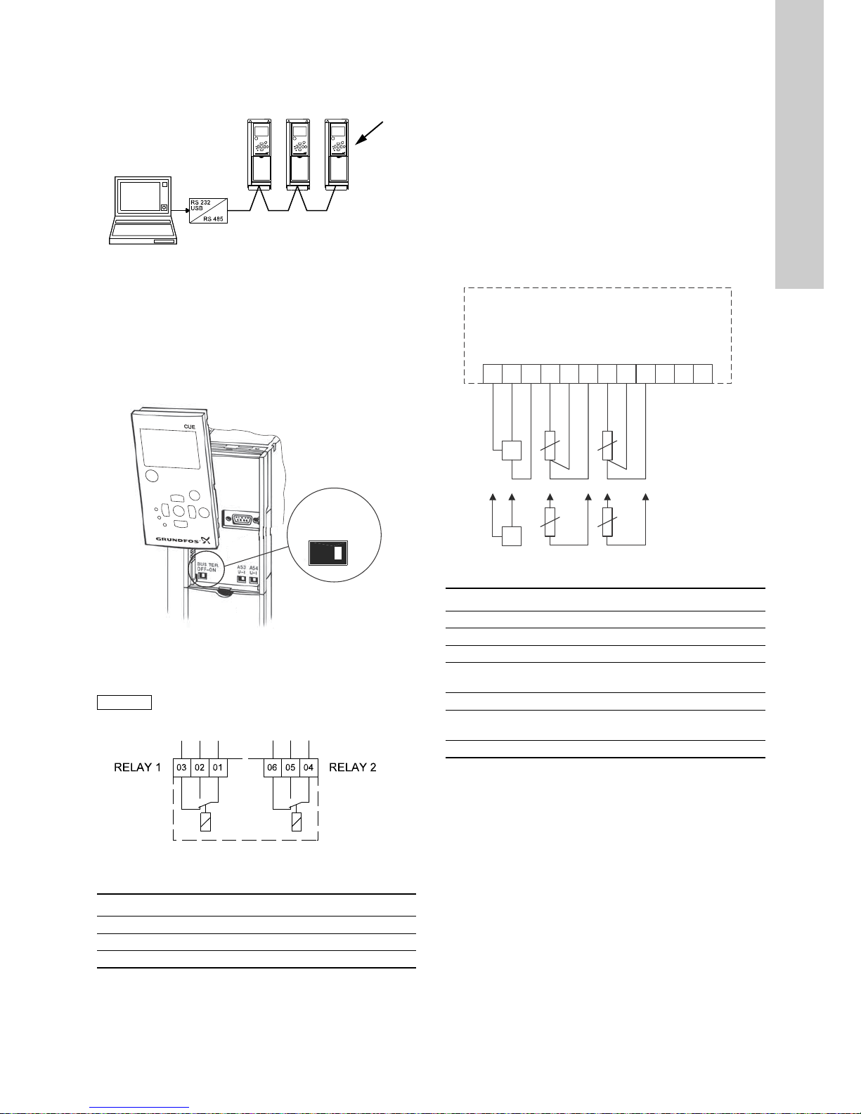
6.3.7 RS-485 GENIbus network connection
One or more CUE units can be connected to a control unit via
GENIbus. See the example in fig. 16.
Fig. 16 Example of an RS-485 GENIbus network
The reference potential, GND, for RS-485 (Y) communication
must be connected to terminal 61.
If more than one CUE unit is connected to a GENIbus network,
the termination contact of the last CUE must be set to "ON"
(termination of the RS-485 port).
The factory setting of the termination contact is "OFF" (not
terminated).
Remove the control panel to set the contact. See fig. 17.
Fig. 17 Setting the termination contact to "ON"
6.4 Connecting the signal relays
Fig. 18 Terminals for signal relays in normal state (not
activated)
6.5 Connecting the MCB 114 sensor input module
The MCB 114 is an option offering additional analog inputs for the
CUE.
6.5.1 Configuration of the MCB 114
The MCB 114 is equipped with three analog inputs for these
sensors:
• One additional sensor 0/4-20 mA. See section 10.8.14 Sensor
2 (3.16).
• Two Pt100/Pt1000 temperature sensors for measurement of
motor bearing temperature or an alternative temperature, such
as liquid temperature. See sections 10.8.19 Temperature
sensor 1 (3.21) and 10.8.20 Temperature sensor 2 (3.22).
When the MCB 114 has been installed, the CUE will automatically
detect if the sensor is Pt100 or Pt1000 when it is switched on.
6.5.2 Wiring diagram, MCB 114
Fig. 19 Wiring diagram, MCB 114
Terminals 10, 11 and 12 are not used.
TM03 9005 2807TM03 9006 2807
Caution
As a precaution, signal cables must be separated
from other groups by reinforced insulation in their
entire lengths.
TM03 8801 2507
Terminal Function
C 1 C 2 Common
NO 1 NO 2 Normally open contact
NC 1 NC 2 Normally closed contact
Bus Ter = ON
OFF ON
BUS TER
C 1
NC 1
NO 1
NC 2
NO 2
C2
TM04 3273 3908
Terminal Type Function
1 (VDO) +24 V out Supply to sensor
2 (I IN) AI 3 Sensor 2, 0/4-20 mA
3 (GND) GND Common frame for analog input
4 (TEMP)
5 (WIRE)
AI 4 Temperature sensor 1, Pt100/Pt1000
6 (GND) GND Common frame for temperature sensor 1
7 (TEMP)
8 (WIRE)
AI 5 Temperature sensor 2, Pt100/Pt1000
9 (GND) GND Common frame for temperature sensor 2
1 98765432
12111
0
VDO
I IN
GND
TEMP
WIRE
GND
TEMP
WIRE
GND
+
-
+
Page 12

English (GB)
12
6.6 EMC-correct installation
This section provides guidelines for good practice when installing
the CUE. Follow these guidelines to meet EN 61800-3, first
environment.
• Use only motor and signal cables with a braided metal screen
in applications without output filter.
• There are no special requirements to supply cables, apart
from local requirements.
• Leave the screen as close to the connecting terminals as
possible. See fig. 20.
• Avoid terminating the screen by twisting the ends. See fig. 21.
Use cable clamps or EMC screwed cable entries instead.
• Connect the screen to frame at both ends for both motor and
signal cables. See fig. 22. If the controller has no cable
clamps, connect only the screen to the CUE. See fig. 23.
• Avoid unscreened motor and signal cables in electrical
cabinets with frequency converters.
• Make the motor cable as short as possible in applications
without output filter to limit the noise level and minimise
leakage currents.
• Screws for frame connections must always be tightened
whether a cable is connected or not.
• Keep main cables, motor cables and signal cables separated
in the installation, if possible.
Other installation methods may give similar EMC results if the
above guidelines for good practice are followed.
Fig. 20 Example of stripped cable with screen
Fig. 21 Do not twist the screen ends
Fig. 22 Example of connection of a 3-conductor bus cable with
screen connected at both ends
Fig. 23 Example of connection of a 3-conductor bus cable with
screen connected at the CUE (controller with no cable
clamps)
6.7 RFI filters
To meet the EMC requirements, the CUE comes with the
following types of built-in radio frequency interference filter (RFI).
Description of RFI filter types
RFI filter types are according to EN 61800-3.
6.7.1 Equipment of c ateg ory C3
• This type of power drive system (PDS) is not intended to be
used on a low-voltage public network which supplies domestic
premises.
• Radio frequency interference is expected if used on such a
network.
TM02 1325 0901TM03 8812 2507
TM03 8732 2407TM03 8731 2407
Voltage
[V]
Typical shaft power P2
[kW]
RFI filter type
3 x 380-500 110-250 C3
3 x 525-690 110-250 C3
C3:
For use in industrial areas with own low-voltage
transformer.
CUEController
CUEController
Page 13

English (GB)
13
6.8 Output filters
Output filters are used for reducing the voltage stress on the
motor windings and the stress on the motor insulation system as
well as for decreasing acoustic noise from the frequency
converter-driven motor.
Two types of output filter are available as accessories for the
CUE:
•dU/dt filters
• sine-wave filters.
Use of output filters
The table below explains in which cases an output filter is
required. From the table it can be seen if a filter is needed, and
which type to use.
The selection depends on:
• pump type
• motor cable length
• the required reduction of the acoustic noise from the motor.
The lengths stated apply to the motor cable.
Motor cable
Fig. 24 Example of installation without filter
Fig. 25 Example of installation with filter. The cable between
the CUE and filter must be short
Fig. 26 Submersible pump without connection box. Frequency
converter and filter installed close to the well
Fig. 27 Submersible pump with connection box and screened
cable. Frequency converter and filter installed far away
from the well and connection box installed close to the
well
Pump type CUE output power dU/dt filter Sine-wave filter
SP, BM, BMB with motor voltage from 380 V and higher All NA 0-300 m
Pumps with MG71 and MG80 up to 1.5 kW < 1.5 kW NA 0-300 m
Reduction of dU/dt, reduced noise emission (Low reduction) All 0-150 m NA
Reduction of dU/dt, Upeak and reduced noice emission (High reduction) All NA 0-300 m
With motors rated 500 V or higher All NA 0-300 m
Note
To meet EN 61800-3, the motor cable must always
be a screened cable, whether an output filter is
installed or not.
The mains cable need not be a screened cable. See
figures 24, 25, 26 and 27.
TM04 4289 1109TM04 4290 1109TM04 4291 1109TM04 4292 1109
Symbol Designation
1 CUE
2Filter
3 Connection box
4 Standard motor
5 Submersible motor
One line Unscreened cable
Double line Screened cable
1
4
124
125
1 32
5
Page 14

English (GB)
14
7. Operating modes
The following operating modes are set on the control panel in the
"OPERATION" menu, display 1.2. See section 10.6.2 Operating
mode (1.2).
Example: Max. curve operation can for instance be used in
connection with venting the pump during installation.
Example: Min. curve operation can for instance be used in
periods with a very small flow requirement.
8. Control modes
The control mode is set on the control panel in the
"INSTALLATION" menu, display 3.1. See section 10.8.1 Control
mode (3.1).
There are two basic control modes:
• Uncontrolled operation (open loop).
• Controlled operation (closed loop) with a sensor connected.
See sections 8.1 Uncontrolled operation (open loop) and
8.2 Controlled operation (closed loop).
8.1 Uncontrolled operation (open loop)
Example: Operation on constant curve can for instance be used
for pumps with no sensor connected.
Example: Typically used in connection with an overall control
system such as the MPC or another external controller.
8.2 Controlled operation (closed loop)
Operating mode Description
Normal
The pump is running in the control mode
selected
Stop
The pump has been stopped (green indicator
light is flashing)
Min. The pump is running at minimum speed
Max. The pump is running at maximum speed
TM03 8813 2507
Min. and max. curves.
The pump speed is kept at a given
set value for minimum and maximum
speed, respectively.
TM03 8479 1607
Constant curve.
The speed is kept at a set value in
the range between the min. and max.
curves.
The setpoint is set in %
corresponding to the required speed.
Min.
Max.
TM03 8475 1607
TM03 8804 2507
Proportional
differential
pressure.
The differential
pressure is reduced
at falling flow rate
and increased at
rising flow rate.
TM03 8476 1607
TM03 8804 2507
Constant
differential
pressure, pump.
The differential
pressure is kept
constant,
independently of
the flow rate.
TM03 8476 1607
TM03 8806 2507
Constant
differential
pressure, system.
The differential
pressure is kept
constant,
independently of
the flow rate.
TM03 8476 1607
TM03 8805 2507
Constant pressure.
The pressure is
kept constant,
independently of
the flow rate.
TM03 8477 1607
TM03 8807 2507
Constant pressure
with stop function.
The outlet pressure
is kept constant at
high flow rate.
On/off operation at
low flow rate.
TM03 8482 1607
TM03 8808 2607
Constant level.
The liquid level is
kept constant,
independently of
the flow rate.
TM03 8482 1607
TM03 8809 2607
Constant level with
stop function.
The liquid level is
kept constant at
high flow rate.
On/off operation at
low flow rate.
TM03 8478 1607
TM03 8810 2507
Constant flow rate.
The flow rate is
kept constant,
independently of
the head.
TM03 8482 1607
TM03 8811 2507
Constant
temperature.
The liquid
temperature is kept
constant,
independently of
the flow rate.
CUE
Δp
CUE
Δp
CUE
Δp
CUE
p
CUE
p
CUE
L
CUE
L
CUE
Q
CUE
t
Page 15

English (GB)
15
9. Menu overview
Fig. 28 Menu overview
Menu structure
The CUE has a startup guide, which is started at the first startup.
After the startup guide, the CUE has a menu structure divided
into four main menus:
1. "GENERAL" gives access to the startup guide for the general
setting of the CUE.
2. "OPERATION" enables the setting of setpoint, selection of
operating mode and resetting of alarms. It is also possible to
see the latest five warnings and alarms.
3. "STATUS" shows the status of the CUE and the pump. It is not
possible to change or set values.
4. "INSTALLATION" gives access to all parameters. Here a
detailed setting of the CUE can be made.
STARTUP GUIDE 0. GENERAL 1. OPERATION
0.1 1.1
1/16 0.2 1.2
2/16 0.24 1.3
3/16 8/16 1.4
4/16 9/16 1.5 - 1.9
5/16 10/16 - 14/16
6/16 8/16 1.10 - 1.14
7/16 16/16
Automatic or manual
setting of the direction
of rotation
Page 16

English (GB)
16
2. STATUS 3. INSTALLATION
2.1 2.10 3.1 3.12 3.24
2.2 2.11 3.2 3.13 3.25
2.3 2.12 3.3 3.14
2.4 2.13 3.3A 3.8
2.5 2.14 3.4 3.16
2.6 2.8 3.5 3.17
2.7 2.16 3.6 3.18
2.8 2.17 3.7 3.19
2.9 3.8 3.20
3.9 3.21
3.10 3.22
3.11 3.23
Page 17

English (GB)
17
10. Setting by means of the control panel
10.1 Control panel
The control panel is used for local setting of the CUE. The
functions available depend on the pump family connected to the
CUE.
Fig. 29 Control panel of the CUE
Editing buttons
Navigating buttons
The editing buttons of the control panel can be set to these
values:
•Active
•Not active.
When set to "Not active" (locked), the editing buttons do not
function. It is only possible to navigate in the menus and read
values.
Activate or deactivate the buttons by pressing the arrow up and
arrow down buttons simultaneously for 3 seconds.
Adjusting the display contrast
Press [OK] and [+] for darker display.
Press [OK] and [-] for brighter display.
Indicator lights
The operating condition of the pump is indicated by the indicator
lights on the front of the control panel. See fig. 29.
The table shows the function of the indicator lights.
Warning
The on/off button on the control panel does not
disconnect the CUE from the power supply and must
therefore not be used as a safety switch.
The on/off button has the highest priority. In "off"
condition, pump operation is not possible.
TM03 8719 2507
Button Function
Makes the pump ready for operation/starts and
stops the pump.
Saves changed values, resets alarms and expands
the value field.
Changes values in the value field.
On/On/
Off
+
-
CUCUE
>
>
>
>
OK
On/On/
Off
OnOn
Off
Alarm
Alarm
On/On/
Off
OK
+
-
Button Function
Navigates from one menu to another. When the
menu is changed, the display shown will always be
the top display of the new menu.
Navigates up and down in the individual menu.
Indicator
light
Function
On (green)
The pump is running or has been stopped by a
stop function.
If flashing, the pump has been stopped by the
user (CUE menu), external start/stop or bus.
Off (orange)
The pump has been stopped with the on/off
button.
Alarm (red) Indicates an alarm or a warning.
>
>
>
>
Page 18

English (GB)
18
Displays, general terms
Figures 30 and 31 show the general terms of the display.
Fig. 30 Example of display in the startup guide
Fig. 31 Example of display in the user menu
10.2 Back to factory settings
Follow this procedure to get back to the factory settings:
1. Switch off the power supply to the CUE.
2. Press [On/Off], [OK] and [+] while switching on the power
supply.
The CUE will reset all parameters to factory settings. The display
will turn on when the reset is completed.
10.3 CUE settings
The startup guide includes all parameters that can be set on the
control panel of the CUE.
The document includes a special table for additional PC Tool
settings and a page where special PC Tool programming details
should be entered.
If you want to download the document, please contact your local
Grundfos company.
10.4 Startup guide
Use the startup guide for the general setting of the CUE including
the setting of the correct direction of rotation.
The startup guide is started the first time when the CUE is
connected to the power supply. It can be restarted in the
"GENERAL" menu. Please note that in this case all previous
settings will be erased.
Bulleted lists show possible settings. Factory settings are shown
in bold.
10.4.1 Welcoming display
• Press [OK]. You will now be guided through the startup guide.
10.4.2 Language (1/16)
Select the language to be used in the display:
10.4.3 Units (2/16)
Select the units to be used in the display:
• SI: m, kW, bar...
• US: ft, HP, psi...
TM04 7313 1810
Display name
Current display / total number
Value field
Display name
Display number, menu name
Value field
Note
Check that equipment connected is ready for startup,
and that the CUE has been connected to the power
supply.
Have nameplate data for motor, pump and CUE at
hand.
• English UK
•English US
•German
• French
• Italian
• Spanish
• Portuguese
• Greek
•Dutch
•Swedish
• Finnish
•Danish
•Polish
• Russian
• Hungarian
• Czech
• Chinese
• Japanese
• Korean.
Page 19

English (GB)
19
10.4.4 Pump family (3/16)
Select pump family according to the pump nameplate:
• CR, CRI, CRN, CRT
• SP, SP-G, SP-NE
•...
Select "Other" if the pump family is not on the list.
10.4.5 Rated motor power (4/16)
Set the rated motor power, P2, according to the motor nameplate:
• 0.55 - 90 kW.
The setting range is size-related, and the factory setting
corresponds to the rated power of the CUE.
10.4.6 Supply voltage (5/16)
Select supply voltage according to the rated supply voltage of the
installation site.
* Single-phase input - three-phase output.
The setting range depends on the CUE type, and the factory
setting corresponds to the rated supply voltage of the CUE.
10.4.7 Max. motor current (6/16)
Set the maximum motor current according to the motor
nameplate:
• 0-999 A.
The setting range depends on the CUE type, and the factory
setting corresponds to a typical motor current at the motor power
selected.
Max. current will be limited to the value on the CUE nameplate,
even if it is set to a higher value during setup.
10.4.8 Speed (7/16)
Set the rated speed according to the pump nameplate:
• 0-9999 min
-1
.
The factory setting depends on previous selections. Based on the
set rated speed, the CUE will automatically set the motor
frequency to 50 or 60 Hz.
10.4.9 Frequency (7A/16)
This display appears only if manual entry of the frequency is
required.
Set the frequency according to the motor nameplate:
• 40-200 Hz.
The factory setting depends on previous selections.
Unit 1 x 200-240 V:*
• 1 x 200 V
• 1 x 208 V
• 1 x 220 V
• 1 x 230 V
• 1 x 240 V.
Unit 3 x 200-240 V:
• 3 x 200 V
• 3 x 208 V
• 3 x 220 V
• 3 x 230 V
• 3 x 240 V.
Unit 3 x 380-500 V:
• 3 x 380 V
• 3 x 400 V
• 3 x 48 V
• 3 x 440 V
• 3 x 460 V
• 3 x 500 V.
Unit 3 x 525-600 V:
• 3 x 575 V.
Unit 3 x 525-690 V:
• 3 x 575 V
• 3 x 690 V.
Page 20

English (GB)
20
10.4.10 Control mode (8/16)
Select the desired control mode. See section 10.8.1 Control
mode (3.1).
• Open loop
• Constant pressure
• Constant differential pressure
• Proportional differential pressure
• Constant flow rate
• Constant temperature
• Constant level
• Constant other value.
The possible settings and the factory setting depend on the pump
family.
The CUE will give an alarm if the control mode selected requires
a sensor and no sensor has been installed. To continue the
setting without a sensor, select "Open loop", and proceed. When
a sensor has been connected, set the sensor and control mode in
the "INSTALLATION" menu.
10.4.11 Rated flow rate (8A/16)
This display appears only if the control mode selected is
proportional differential pressure.
Set the rated flow rate according to the pump nameplate:
• 1-6550 m
3
/h.
10.4.12 Rated head (8 B/16 )
This display only appears if the control mode selected is
proportional differential pressure.
Set the rated head according to the pump nameplate:
• 1-999 m.
10.4.13 Sensor connected to terminal 54 (9/16)
Set the measuring range of the connected sensor with a signal
range of 4-20 mA. The measuring range depends on the control
mode selected:
If the control mode selected is "Constant other value", or if the
measuring range selected is "Other", the sensor must be set
according to the next section, display 9A/16.
Proportional differential pressure:
• 0-0.6 bar
•0-1 bar
• 0-1.6 bar
• 0-2.5 bar
•0-4 bar
•0-6 bar
• 0-10 bar
•Other.
Constant differential pressure:
• 0-0.6 bar
• 0-1.6 bar
• 0-2.5 bar
•0-4 bar
• 0-6 bar
• 0-10 bar
•Other.
Constant pressure:
• 0-2.5 bar
•0-4 bar
•0-6 bar
• 0-10 bar
• 0-16 bar
• 0-25 bar
•Other.
Constant flow rate:
•1-5 m
3
/h
•2-10 m
3
/h
•6-30 m
3
/h
•8-75 m
3
/h
•Other.
Constant temperature:
• -25 to 25 °C
• 0 to 25 °C
• 50 to 100 °C
• 0 to 80 °C
•Other.
Constant level:
• 0-0.1 bar
• 0-1 bar
• 0-2.5 bar
• 0-6 bar
• 0-10 bar
•Other.
Page 21

English (GB)
21
10.4.14 Another sensor connected to terminal 54 (9A/16)
This display only appears when the control mode "Constant other
value" or the measuring range "Other" has been selected in
display 9/16.
• Sensor output signal:
0-20 mA
4-20 mA.
• Unit of measurement of sensor:
bar, mbar, m, kPa, psi, ft, m
3
/h, m3/min, m3/s, l/h, l/min, l/s,
gal/h, gal/m, gal/s, ft
3
/min, ft3/s, °C, °F, %.
• Sensor measuring range.
The measuring range depends on the sensor connected and the
measuring unit selected.
10.4.15 Priming and venting (10/16)
See the installation and operating instructions of the pump.
The general setting of the CUE is now completed, and the startup
guide is ready for setting the direction of rotation:
• Press [OK] to go on to automatic or manual setting of the
direction of rotation.
10.4.16 Automatic setting of the direction of rotation (11/16)
The CUE automatically tests and sets the correct direction of
rotation without changing the cable connections.
This test is not suitable for certain pump types and will in certain
cases not be able to determine with certainty the correct direction
of rotation. In these cases, the CUE changes over to manual
setting where the direction of rotation is determined on the basis
of the installer's observations.
Information displays.
• Press [OK] to continue.
The pump starts after 10 seconds.
It is possible to interrupt the test and return to the previous
display.
The pump runs with both directions of rotation and stops
automatically.
It is possible to interrupt the test, stop the pump and go to manual
setting of the direction of rotation.
Warning
During the test, the pump will run for a short time.
Ensure that no personnel or equipment is in danger!
Note
Before setting the direction of rotation, the CUE will
make an automatic motor adaptation of certain pump
types. This will take a few minutes. The adaptation is
carried out during standstill.
The correct direction of
rotation has now been set.
• Press [OK] to set the
setpoint.
See section
10.4.17 Setpoint (8/16).
The automatic setting of the
direction of rotation has failed.
• Press [OK] to go to manual
setting of the direction of
rotation.
Page 22
English (GB)
22
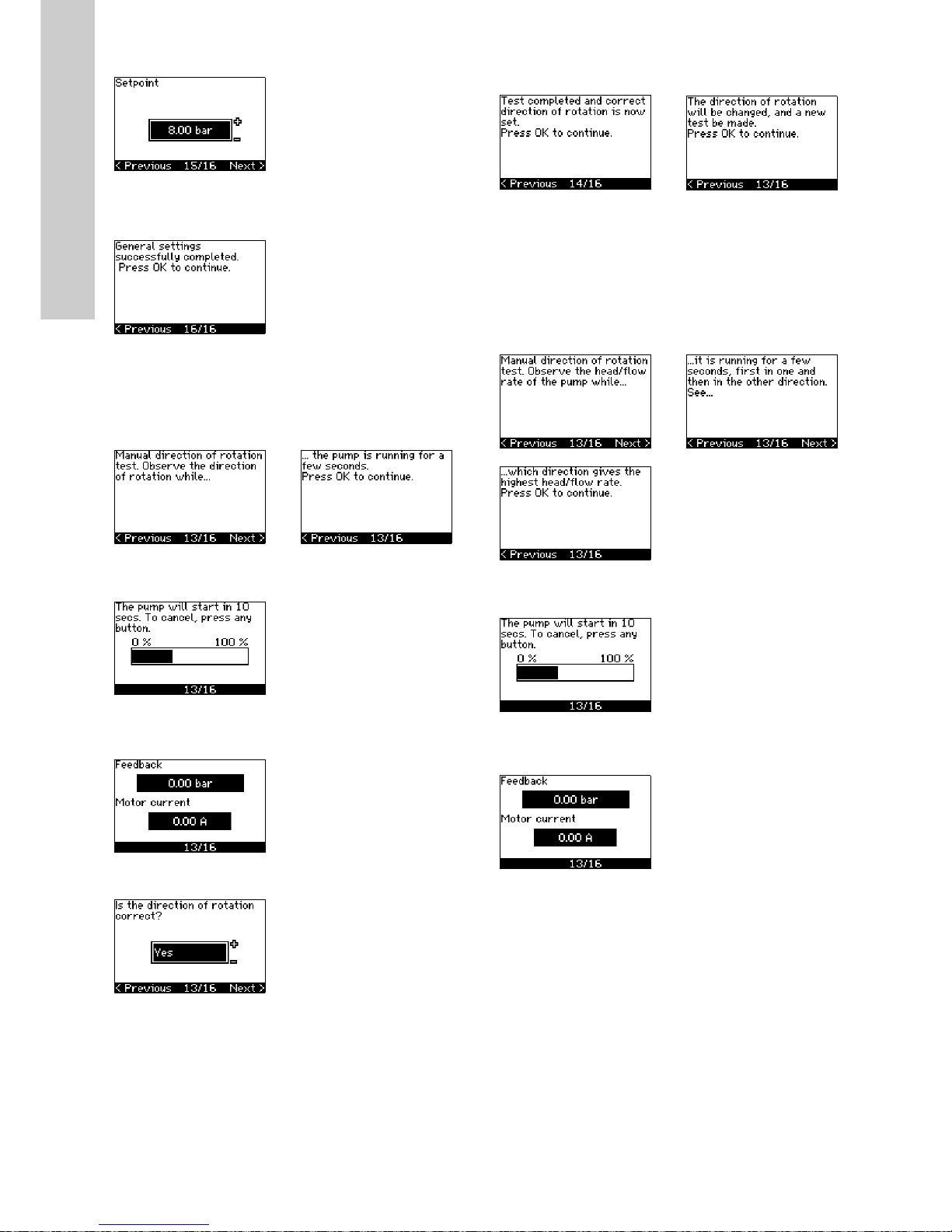
10.4.17 Setpoint (8/16)
Set the setpoint according to the control mode and sensor
selected.
10.4.18 General settings are completed (16/16)
• Press [OK] to make the pump ready for operation or start the
pump in the "Normal" operating mode. Then display 1.1 of the
"OPERATION" menu will appear.
10.4.19 Manual setting when the direction of rotation is
visible (13/16)
It must be possible to observe the motor fan or shaft.
Information displays.
• Press [OK] to continue.
The pump starts after 10 seconds.
It is possible to interrupt the test and return to the previous
display.
The pressure will be shown during the test if a pressure sensor is
connected. The motor current is always shown during the test.
State if the direction of rotation is correct.
10.4.20 Manual setting when the direction of rotation is not
visible (13/16)
It must be possible to observe the head or flow rate.
Information displays.
• Press [OK] to continue.
The pump starts after 10 seconds.
It is possible to interrupt the test and return to the previous
display.
The pressure will be shown during the test if a pressure sensor is
connected. The motor current is always shown during the test.
•Yes •No
The correct direction of
rotation has now been set.
• Press [OK] to set the
setpoint.
See section
10.4.17 Setpoint (8/16).
The direction of rotation is not
correct.
• Press [OK] to repeat the test
with the opposite direction
of rotation.
Page 23

English (GB)
23
The first test is completed.
• Write down the pressure and/or flow rate, and press OK to
continue the manual test with the opposite direction of
rotation.
The pump starts after 10 seconds.
It is possible to interrupt the test and return to the previous
display.
The pressure will be shown during the test if a pressure sensor is
connected. The motor current is always shown during the test.
The second test is completed.
Write down the pressure and/or flow rate, and state which test
gave the highest pump performance:
•First test
• Second test
• Perform new test.
The correct direction of rotation has now been set.
• Press [OK] to set the setpoint. See section 10.4.17 Setpoint
(8/16).
10.5 GENERAL
The menu makes it possible to return to the startup guide, which
is usually only used during the first startup of the CUE.
10.5.1 Return to startup guide (0.1)
State your choice:
•Yes
•No.
If you select "Yes", all settings will be erased, and the entire
startup guide must be completed. The CUE will return to the
startup guide, and new settings can be made. Additional settings
and the settings available in section 10. Setting by means of the
control panel will not require a reset.
Back to factory settings
Press [On/Off], [OK] and [+] for a complete reset to factory
settings.
10.5.2 Type code change (0.2)
This display is for service use only.
Note
If the startup guide is started, all previous settings
will be erased!
Note
The startup guide must be carried out on a cold
motor!
Repeating the startup guide may lead to heating of
the motor.
Page 24
English (GB)
24
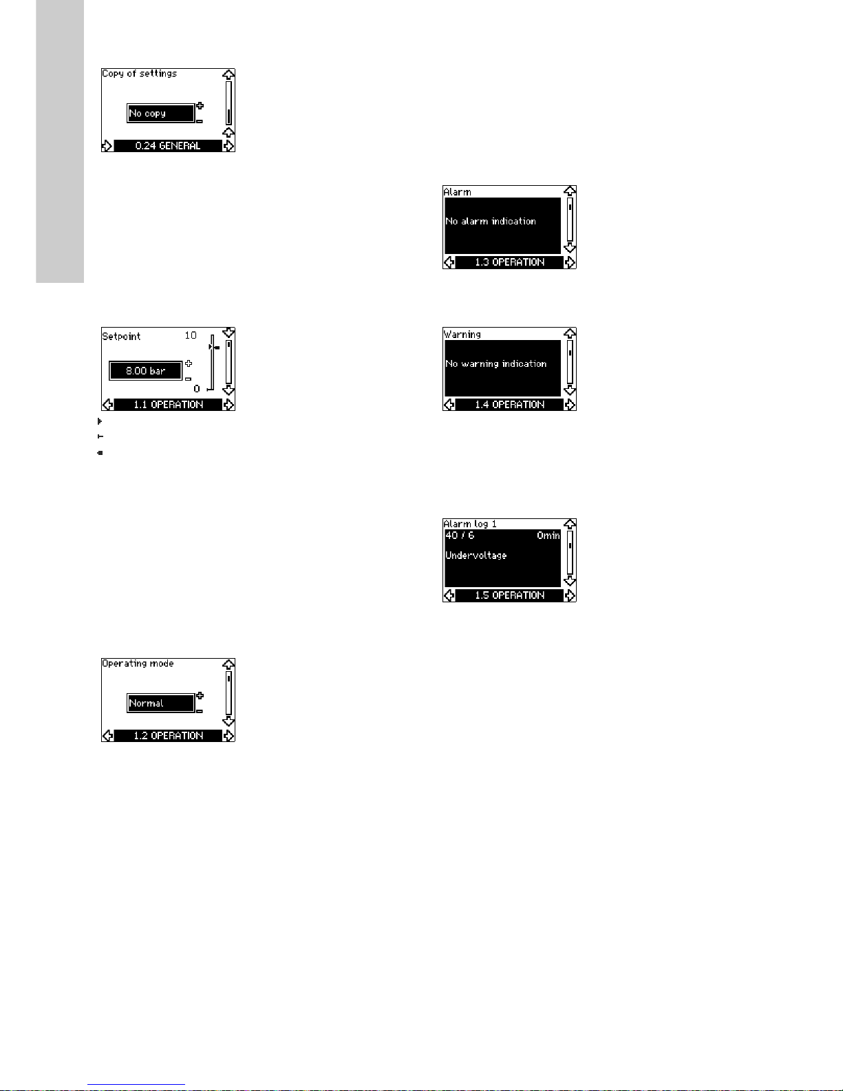
10.5.3 Copy of settings
It is possible to copy the settings of a CUE and reuse them in
another one.
Options:
• No copy.
• to CUE (copies the settings of the CUE).
• to control panel (copies the settings to another CUE).
The CUE units must have the same firmware version. See section
10.7.16 Firmware version (2.16).
10.6 OPERATION
10.6.1 Setpoint (1.1)
Setpoint set
Actual setpoint
Actual value
Set the setpoint in the units of the feedback sensor.
In "Open loop" control mode, the setpoint is set in % of the
maximum performance. The setting range will be between the
min. and max. curves. See fig. 38.
In all other control modes except proportional differential
pressure, the setting range is equal to the sensor measuring
range. See fig. 39.
In "Proportional differential pressure" control mode, the setting
range is equal to 25 % to 90 % of max. head. See fig. 40.
If the pump is connected to an external setpoint signal, the value
in this display will be the maximum value of the external setpoint
signal. See section 13.2 External setpoint.
10.6.2 Operating mode (1.2)
Set one of the following operating modes:
• Normal (duty)
•Stop
•Min.
•Max.
The operating modes can be set without changing the setpoint
setting.
10.6.3 Fault indications
Faults may result in two types of indication: Alarm or warning.
An alarm will activate an alarm indication in CUE and cause the
pump to change operating mode, typically to stop. However, for
some faults resulting in alarm, the pump is set to continue
operating even if there is an alarm.
A warning will activate a warning indication in CUE, but the pump
will not change operating or control mode.
Alarm (1.3)
In case of an alarm, the cause will appear in the display. See
section 15.1 Warning and alarm list.
Warning (1.4)
In case of a warning, the cause will appear in the display. See
section 15.1 Warning and alarm list.
10.6.4 Fault log
For both fault types, alarm and warning, the CUE has a log
function.
Alarm log (1.5 - 1 .9)
In case of an alarm, the last five alarm indications will appear in
the alarm log. "Alarm log 1" shows the latest alarm, "Alarm log 2"
shows the latest alarm but one, etc.
The display shows three pieces of information:
• the alarm indication
• the alarm code
• the number of minutes the pump has been connected to the
power supply after the alarm occurred.
Page 25
English (GB)
25
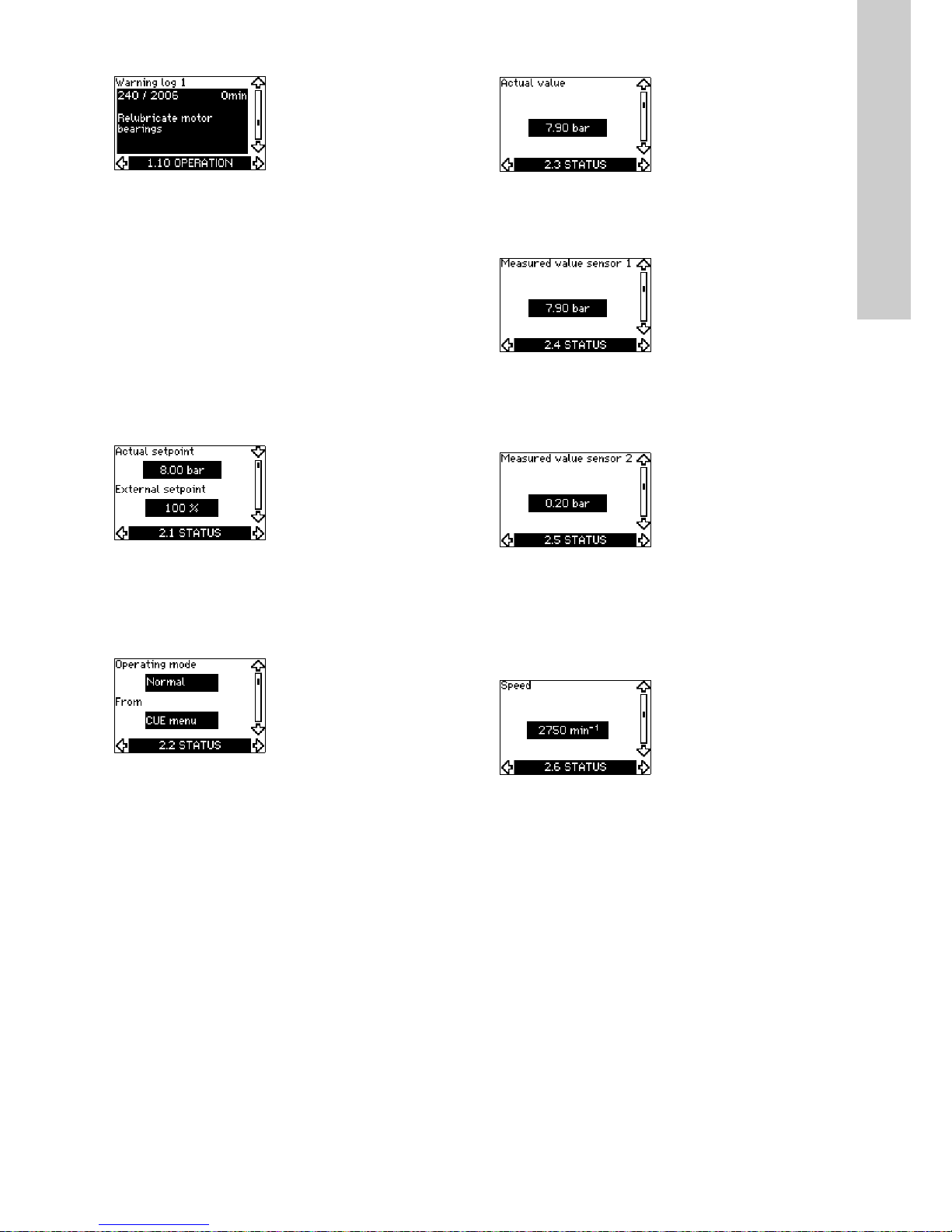
Warning log (1.10 - 1.14)
In case of a warning, the last five warning indications will appear
in the warning log. "Warning log 1" shows the latest fault,
"Warning log 2" shows the latest fault but one, etc.
The display shows three pieces of information:
• the warning indication
• the warning code
• the number of minutes the pump has been connected to the
power supply after the warning occurred.
10.7 STATUS
The displays appearing in this menu are status displays only. It is
not possible to change or set values.
The tolerance of the displayed value is stated under each display.
The tolerances are stated as a guide in % of the maximum values
of the parameters.
10.7.1 Actual setpoint (2.1)
This display shows the actual setpoint and the external setpoint.
The actual setpoint is shown in the units of the feedback sensor.
The external setpoint is shown in a range of 0 to 100 %. If the
external setpoint influence is deactivated, the value 100 % is
shown. See section 13.2 External setpoint.
10.7.2 Operating mode (2.2)
This display shows the actual operating mode (Normal, Stop, Min.
or Max.). Furthermore, it shows where this operating mode was
selected (CUE menu, Bus, External or On/off button).
10.7.3 Actual value (2.3)
This display shows the actual value controlled.
If no sensor is connected to the CUE, "-" will appear in the
display.
10.7.4 Measured value, sensor 1 (2.4)
This display shows the actual value measured by sensor 1
connected to terminal 54.
If no sensor is connected to the CUE, "-" will appear in the
display.
10.7.5 Measured value, sensor 2 (2.5)
This display is only shown if an MCB 114 sensor input module
has been installed.
The display shows the actual value measured by sensor 2
connected to an MCB 114.
If no sensor is connected to the CUE, "-" will appear in the
display.
10.7.6 Speed (2.6)
Tolerance: ± 5 %
This display shows the actual pump speed.
Page 26
English (GB)
26
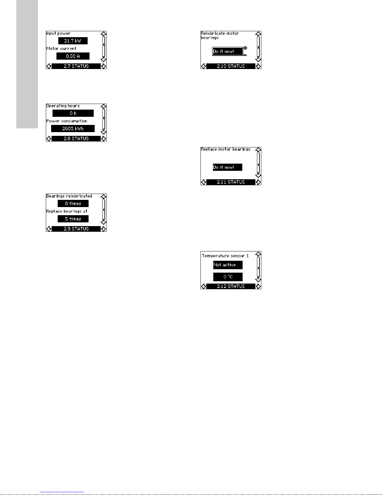
10.7.7 Input power and motor current (2.7)
Tolerance: ± 10 %
This display shows the actual pump input power in W or kW and
the actual motor current in ampere [A].
10.7.8 Operating hours and power consumption (2.8)
Tolerance: ± 2 %
This display shows the number of operating hours and the power
consumption. The value of operating hours is an accumulated
value and cannot be reset. The value of power consumption is an
accumulated value calculated from the unit's birth, and it cannot
be reset.
10.7.9 Lubrication status of motor bearings (2.9)
This display shows how many times the user has given the
lubrication stated and when to replace the motor bearings.
When the motor bearings have been relubricated, confirm this
action in the "INSTALLATION" menu. See section
10.8.18 Confirming relubrication/replacement of motor bearings
(3.20). When relubrication is confirmed, the figure in the above
display will be increased by one.
10.7.10 Time until relubrication of motor bearings (2.10)
This display is only shown if display 2.11 is not shown.
The display shows when to relubricate the motor bearings. The
controller monitors the operating pattern of the pump and
calculates the period between bearing lubrications. If the
operating pattern changes, the calculated time until relubrication
may change as well.
The estimated time until relubrication takes into account if the
pump has been running with reduced speed.
See section 10.8.18 Confirming relubrication/replacement of
motor bearings (3.20).
10.7.11 Time until replacement of motor bearings (2.11)
This display is only shown if display 2.10 is not shown.
The display shows when to replace the motor bearings. The
controller monitors the operating pattern of the pump and
calculates the period between bearing replacements.
The estimated time until replacement of motor bearings takes into
account if the pump has been running with reduced speed.
See section 10.8.18 Confirming relubrication/replacement of
motor bearings (3.20).
10.7.12 Temperature sensor 1 (2.12)
This display is only shown if an MCB 114 sensor input module
has been installed.
The display shows the measuring point and the actual value
measured by a Pt100/Pt1000 temperature sensor 1 connected to
the MCB 114. The measuring point is selected in display 3.21.
If no sensor is connected to the CUE, "-" will appear in the
display.
Page 27

English (GB)
27
10.7.13 Temperature sensor 2 (2.13)
This display is only shown if an MCB 114 sensor input module
has been installed.
The display shows the measuring point and the actual value
measured by a Pt100/Pt1000 temperature sensor 2 connected to
the MCB 114. The measuring point is selected in display 3.22.
If no sensor is connected to the CUE, "-" will appear in the
display.
10.7.14 Flow rate (2.14)
This display is only shown if a flowmeter has been configured.
The display shows the actual value measured by a flowmeter
connected to the digital pulse input (terminal 33) or the analog
input (terminal 54).
10.7.15 Accumulated flow (2.8)
This display is only shown if a flowmeter has been configured.
The display shows the value of the accumulated flow and the
specific energy for the transfer of the pumped liquid.
The flow measurement can be connected to the digital pulse input
(terminal 33) or the analog input (terminal 54).
10.7.16 Firmware version (2.16)
This display shows the version of the software.
10.7.17 Configuration file (2.17)
This display shows the configuration file.
10.8 INSTALLATION
10.8.1 Control mode (3.1)
Select one of the following control modes:
• Open loop
• Constant pressure
• Constant differential pressure
• Proportional differential pressure
• Constant flow rate
• Constant temperature
• Constant level
• Constant other value.
10.8.2 Controller (3.2)
The CUE has a factory setting of gain (K
p
) and integral time (Ti).
However, if the factory setting is not the optimum setting, the gain
and the integral time can be changed in the display.
•The gain (K
p
) can be set within the range from 0.1 to 20.
• The integral time (Ti) can be set within the range from 0.1 to
3600 s. If you select 3600 s, the controller will function as a P
controller.
• Furthermore, it is possible to set the controller to inverse
control, meaning that if the setpoint is increased, the speed
will be reduced. In the case of inverse control, the gain (K
p
)
must be set within the range from -0.1 to -20.
Note
If the pump is connected to a bus, the control mode
cannot be selected via the CUE. See section
13.3 GENIbus signal.
Page 28

English (GB)
28
The table below shows the suggested controller settings:
* T
i
= 100 seconds (factory setting).
1. Heating systems are systems in which an increase in pump
performance will result in a rise in temperature at the sensor.
2. Cooling systems are systems in which an increase in pump
performance will result in a drop in temperature at the sensor.
L
1
= Distance in [m] between pump and sensor.
L
2
= Distance in [m] between heat exchanger and sensor.
How to set the PI controller
For most applications, the factory setting of the controller
constants K
p
and Ti will ensure optimum pump operation.
However, in some applications an adjustment of the controller
may be needed.
Proceed as follows:
1. Increase the gain (K
p
) until the motor becomes unstable.
Instability can be seen by observing if the measured value
starts to fluctuate. Furthermore, instability is audible as the
motor starts hunting up and down.
As some systems, such as temperature controls, are slowreacting, it may be difficult to observe that the motor is
unstable.
2. Set the gain (K
p
) to half the value of the value which made the
motor unstable. This is the correct setting of the gain.
3. Reduce the integral time (T
i
) until the motor becomes
unstable.
4. Set the integral time (T
i
) to twice the value which made the
motor unstable. This is the correct setting of the integral time.
General rules of thumb:
• If the controller is too slow-reacting, increase K
p
.
• If the controller is hunting or unstable, dampen the system by
reducing K
p
or increasing Ti.
10.8.3 External setpoint (3.3)
The input for external setpoint signal (terminal 53) can be set to
the following types:
•Active
• Not active.
If you select "Active", the actual setpoint is influenced by the
signal connected to the external setpoint input. See section
13.2 External setpoint.
System/application
K
p
T
i
Heating
system
1)
Cooling
system
2)
0.2 0.5
SP, SP-G, SP-NE: 0.5 0.5
0.2 0.5
SP, SP-G, SP-NE: 0.5 0.5
0.2 0.5
- 2.5 100
0.5 - 0.5 10 + 5L
2
0.5 10 + 5L
2
0.5 - 0.5 30 + 5L2*
0.5 0.5*
0.5
L
1
< 5 m: 0.5*
L
1
> 5 m: 3*
L
1
> 10 m: 5*
CUE
p
CUE
p
CUE
Q
CUE
L
t
L
2
CUE
Δt
L
2
CUE
t
L
2
CUE
CUE
Δp
Δp
L
1
CUE
Page 29
English (GB)
29
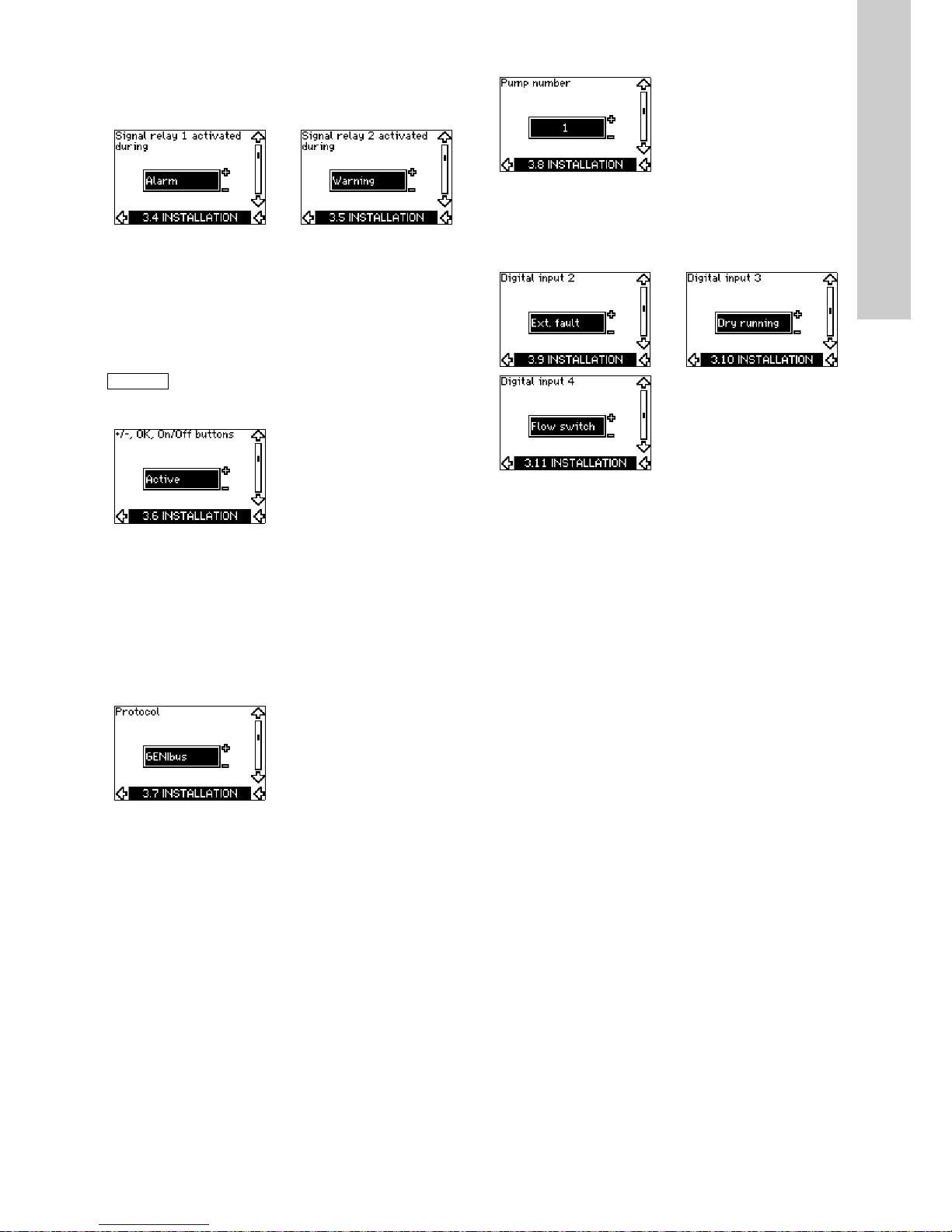
10.8.4 Signal relays 1 and 2 (3.4 and 3.5)
The CUE has two signal relays. In the display below, select in
which operating situations the signal relay should be activated.
10.8.5 Buttons on the CUE (3.6)
The editing buttons (+, -, On/Off, OK) on the control panel can be
set to these values:
•Active
• Not active.
When set to "Not active" (locked), the editing buttons do not
function. Set the buttons to "Not active" if the pump should be
controlled via an external control system.
Activate the buttons by pressing the arrow up and arrow down
buttons simultaneously for 3 seconds.
10.8.6 Protocol (3.7)
This display shows the protocol selection for the RS-485 port of
the CUE. The protocol can be set to these values:
• GENIbus
•FC
•FC MC.
If you select "GENIbus", the communication is set according to
the Grundfos GENIbus standard. FC and FC MC are for service
purposes only.
10.8.7 Pump number (3.8)
This display shows the GENIbus number. A number between 1
and 199 can be allocated to the pump. In the case of bus
communication, a number must be allocated to each pump.
The factory setting is "-".
10.8.8 Digital inputs 2, 3 and 4 (3.9 to 3.11)
The digital inputs of the CUE (terminal 19, 32 and 33) can be set
individually to different functions.
Select one of the following functions:
• Min. (min. curve)
• Max. (max. curve)
• Ext. fault (external fault)
• Flow switch
• Alarm reset
• Dry running (from external sensor)
• Accumulated flow (pulse flow, only terminal 33)
•Not active.
The selected function is active when the digital input is activated
(closed contact). See also section 13.1 Digital inputs.
Min.
When the input is activated, the pump will operate according to
the min. curve.
Max.
When the input is activated, the pump will operate according to
the max. curve.
Ext. fault
When the input is activated, a timer will be started. If the input is
activated for more than 5 seconds, an external fault will be
indicated. If the input is deactivated, the fault condition will cease
and the pump can only be restarted manually by resetting the
fault indication.
Signal relay 1 Signal relay 2
• Ready
•Alarm
• Operation
• Pump running
• Not active
• Warning
• Relubricate.
• Ready
•Alarm
• Operation
• Pump running
• Not active
• Warning
• Relubricate.
Note
For the distinction between alarm and warning, see
section 10.6.3 Fault indications.
Page 30
English (GB)
30
Flow switch
When this function is selected, the pump will be stopped when a
connected flow switch detects low flow.
It is only possible to use this function if the pump is connected to
a pressure sensor or a level sensor, and the stop function is
activated. See sections 10.8.11 Constant pressure with stop
function (3.14) and 10.8.12 Constant level with stop function
(3.14).
Alarm reset
When the input has been activated, the alarm is reset if the cause
of the alarm no longer exists.
Dry running
When this function is selected, lack of inlet pressure or water
shortage can be detected. This requires the use of an accessory,
such as:
• a Grundfos Liqtec
®
dry-running switch
• a pressure switch installed on the suction side of a pump
• a float switch installed on the suction side of a pump.
When lack of inlet pressure or water shortage (dry running) is
detected, the pump will be stopped. The pump cannot restart as
long as the input is activated.
Restarts may be delayed by up to 30 minutes, depending of the
pump family.
Accumulated flow
When this function is set for digital input 4 and a pulse sensor is
connected to terminal 33, the accumulated flow can be
measured.
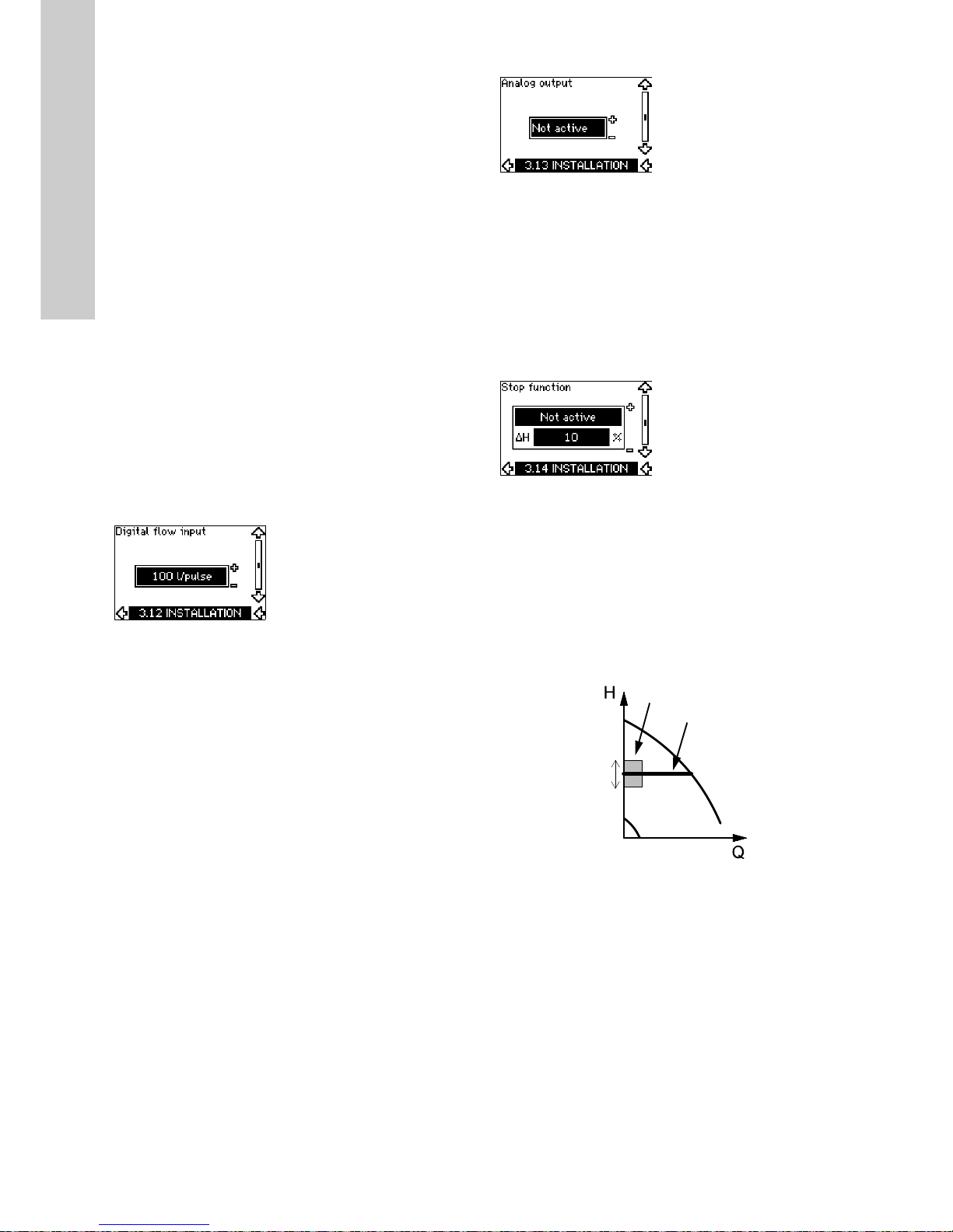
10.8.9 Digital flow input (3.12)
This display appears only if a flowmeter has been configured in
display 3.11.
The display is used for setting the volume for every pulse for the
"Accumulated flow" function with a pulse sensor connected to
terminal 33.
Setting range:
• 0-1000 litres/pulse.
The volume can be set in the unit selected in the startup guide.
10.8.10 Analog output (3.13)
The analog output can be set to show one of the following
options:
• Feedback
• Power input
• Speed
• Output frequency
• External sensor
• Limit 1 exceeded
• Limit 2 exceeded
•Not active.
10.8.11 Constant pressure with stop function (3.14)
Settings
The stop function can be set to these values:
•Active
• Not active.
The on/off band can be set to these values:
• ΔH is factory-set to 10 % of the actual setpoint.
• ΔH can be set within the range from 5 % to 30 % of the actual
setpoint.
Description
The stop function is used for changing between on/off operation
at low flow and continuous operation at high flow.
Fig. 32 Constant pressure with stop function. Difference
between start and stop pressures (ΔH)
Low flow can be detected in two different ways:
1. A built-in "low-flow detection function" which functions if the
digital input is not set up for flow switch.
2. A flow switch connected to the digital input.
TM03 8477 1607
Stop pressure
ΔH
Start pressure
Continuous operation
On/off operation
Page 31
English (GB)
31
1. Low-flow detection function
The pump will check the flow regularly by reducing the speed for
a short time. If there is no or only a small change in pressure, this
means that there is low flow.
The speed will be increased until the stop pressure (actual
setpoint + 0.5 x ΔH) is reached and the pump will stop after a few
seconds. The pump will restart at the latest when the pressure
has fallen to the start pressure (actual setpoint - 0.5 x ΔH).
If the flow in the off period is higher than the low-flow limit, the
pump will restart before the pressure has fallen to the start
pressure.
When restarting, the pump will react in the following way:
1. If the flow is higher than the low-flow limit, the pump will return
to continuous operation at constant pressure.
2. If the flow is lower than the low-flow limit, the pump will
continue in start/stop operation. It will continue in start/stop
operation until the flow is higher than the low-flow limit. When
the flow is higher than the low-flow limit, the pump will return
to continuous operation.
2. Low-flow detection with flow switch
When the digital input is activated because there is low flow, the
speed will be increased until the stop pressure (actual setpoint +
0.5 x ΔH) is reached, and the pump will stop. When the pressure
has fallen to start pressure, the pump will start again. If there is
still no flow, the pump will reach the stop pressure and stop. If
there is flow, the pump will continue operating according to the
setpoint.
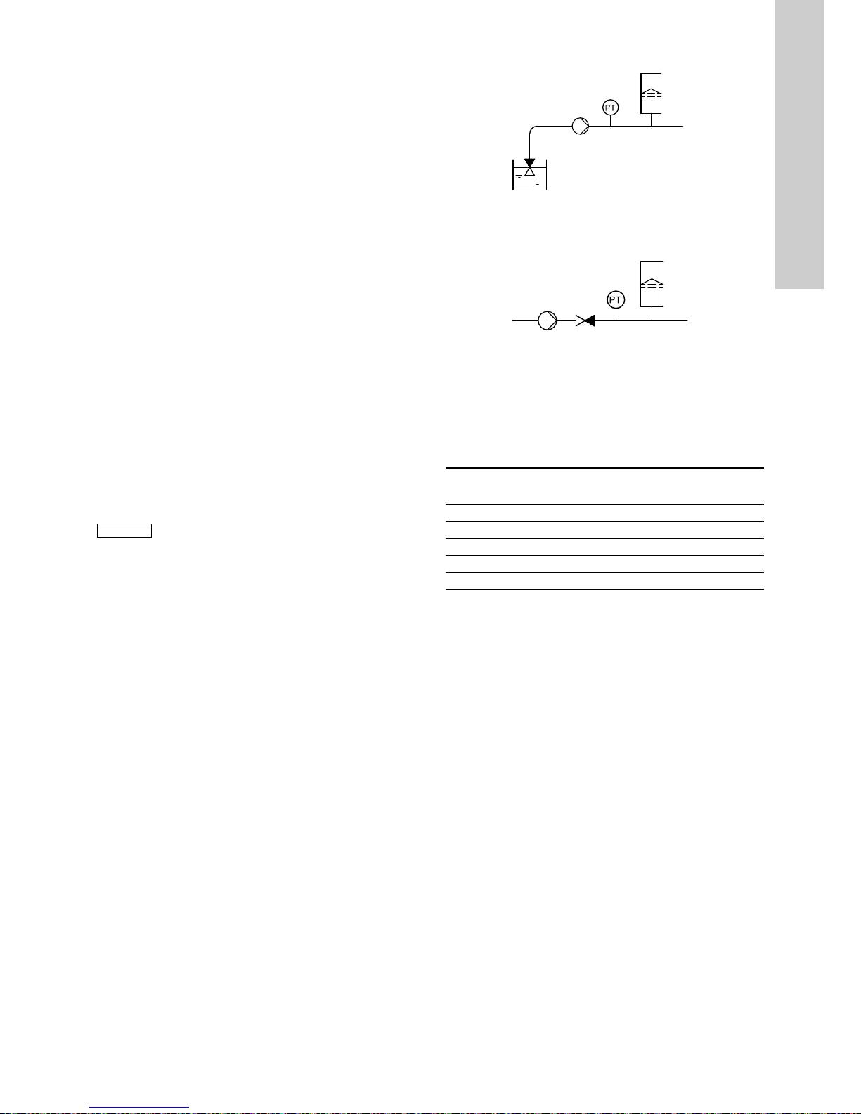
Operating conditions for the stop function
It is only possible to use the stop function if the system
incorporates a pressure sensor, a non-return valve and a
diaphragm tank.
Fig. 33 Position of the non-return valve and pressure sensor in
system with suction lift operation
Fig. 34 Position of the non-return valve and pressure sensor in
system with positive inlet pressure
Diaphragm tank
The stop function requires a diaphragm tank of a certain minimum
size. The tank must be installed as close as possible after the
pump and the precharge pressure must be 0.7 x actual setpoint.
Recommended diaphragm tank size:
If a diaphragm tank of the above size is installed in the system,
the factory setting of ΔH is the correct setting.
If the tank installed is too small, the pump will start and stop too
often. This can be remedied by increasing ΔH.
Caution
The non-return valve must always be installed before
the pressure sensor. See figures 33 and 34.
If a flow switch is used to detect low flow, the switch
must be installed on the system side after the
diaphragm tank.
TM03 8582 1907TM03 8583 1907
Rated flow rate of pump
[m
3
/h]
Typical diaphragm tank size
[litres]
0-6 8
7-24 18
25-40 50
41-70 120
71-100 180
Pressure sensor
Diaphragm tank
Non-return
valve
Pump
Diaphragm tank
Pressure sensor
Pump Non-return valve
Page 32

English (GB)
32
10.8.12 Constant level with stop function (3.14)
Settings
The stop function can be set to these values:
•Active
• Not active.
The on/off band can be set to these values:
• ΔH is factory-set to 10 % of the actual setpoint.
• ΔH can be set within the range from 5 % to 30 % of the actual
setpoint.
A built-in low-flow detection function will automatically measure
and store the power consumption at approx. 50 % and 85 % of
the rated speed.
If you select "Active", proceed as follows:
1. Close the isolating valve to create a no-flow condition.
2. Press [OK] to start the auto-tuning.
Description
The stop function is used for changing between on/off operation
at low flow and continuous operation at high flow.
Fig. 35 Constant level with stop function. Difference between
start and stop levels (ΔH)
Low flow can be detected in two different ways:
1. With the built-in low-flow detection function.
2. With a flow switch connected to a digital input.
1. Low-flow detection function
The built-in low-flow detection is based on the measurement of
speed and power.
When low flow is detected, the pump will stop. When the level has
reached the start level, the pump will start again. If there is still no
flow, the pump will reach the stop level and stop. If there is flow,
the pump will continue operating according to the setpoint.
2. Low-flow detection with flow switch
When the digital input is activated because of low flow, the speed
will be increased until the stop level (actual setpoint - 0.5 x ΔH) is
reached, and the pump will stop. When the level has reached the
start level, the pump will start again. If there is still no flow, the
pump will reach the stop level and stop. If there is flow, the pump
will continue operating according to the setpoint.
Operating conditions for the stop function
It is only possible to use the constant level stop function if the
system incorporates a level sensor, and all valves can be closed.
10.8.13 Sensor 1 (3.8)
Setting of sensor 1 connected to terminal 54. This is the feedback
sensor.
Select among the following values:
• Sensor output signal:
0-20 mA
4-20 mA.
• Sensor unit of measurement:
bar, mbar, m, kPa, psi, ft, m
3
/h, m3/s, l/s, gpm, °C, °F, %.
• Sensor measuring range.
10.8.14 Sensor 2 (3.16)
Setting of sensor 2 connected to an MCB 114 sensor input
module.
Select among the following values:
• Sensor output signal:
0-20 mA
4-20 mA.
• Sensor unit of measurement:
bar, mbar, m, kPa, psi, ft, m
3
/h, m3/s, l/s, gpm, °C, °F, %.
• Sensor measuring range:
0-100 %.
TM03 9099 3307
Star t level
ΔH
Stop level
Page 33

English (GB)
33
10.8.15 Duty/standby (3.17)
Settings
The duty/standby function can be set to these values:
•Active
• Not active.
Activate the duty/standby function as follows:
1. Connect one of the pumps to the mains supply.
Set the duty/standby function to "Not active".
Make the necessary settings in the "OPERATION" and
"INSTALLATION" menus.
2. Set the operating mode to "Stop" in the "OPERATION" menu.
3. Connect the other pump to the mains supply.
Make the necessary settings in the "OPERATION" and
"INSTALLATION" menus.
Set the duty/standby function to "Active".
The running pump will search for the other pump and
automatically set the duty/standby function of this pump to
"Active". If it cannot find the other pump, a fault will be indicated.
The duty/standby function applies to two pumps connected in
parallel and controlled via GENIbus. Each pump must be
connected to its own CUE and sensor.
The primary targets of the function is the following:
• To start the standby pump if the duty pump is stopped due to
an alarm.
• To alternate the pumps at least every 24 hours.
10.8.16 Operating range (3.18)
How to set the operating range:
• Set the min. speed within the range from a pump-dependent
min. speed to the adjusted max. speed. The factory setting
depends on the pump family.
• Set the max. speed within the range from adjusted min. speed
to the pump-dependent max. speed. The factory setting will be
equal to 100 %, i.e. the speed stated on the pump nameplate.
The area between the min. and max. speed is the actual
operating range of the pump.
The operating range can be changed by the user within the
pump-dependent speed range.
For some pump families, oversynchronous operation (max. speed
above 100 %) will be possible. This requires an oversize motor to
deliver the shaft power required by the pump during
oversynchronous operation.
Fig. 36 Setting of the min. and max. curves in % of maximum performance
Note
The two pumps must be connected electrically via
the GENIbus, and nothing else must be connected
on the GENIbus.
TM04 3581 4608
Nominal speed Max. speed
Actual speed range
Min. speed
Pump-dependent speed range
Min. speed, adjusted
Max. speed, adjusted
Speed [%]
Min.
Max.
100 %
Page 34

English (GB)
34
10.8.17 Motor bearing monitoring (3.19)
The motor bearing monitoring function can be set to these values:
•Active
• Not active.
When the function is set to "Active", the CUE will give a warning
when the motor bearings are due to be relubricated or replaced.
Description
The motor bearing monitoring function is used to give an
indication when it is time to relubricate or replace the motor
bearings. See displays 2.10 and 2.11.
The warning indication and the estimated time take into account if
the pump has been running with reduced speed. The bearing
temperature is included in the calculation if temperature sensors
are installed and connected to an MCB 114 sensor input module.
10.8.18 Confirming relubrication/replacement of motor
bearings (3.20)
This function can be set to these values:
• Relubricated
•Replaced
• Nothing done.
When the motor bearings have been relubricated or replaced,
confirm this action in the above display by pressing [OK].
Relubricated
When the warning "Relubricate motor bearings" has been
confirmed,
• the counter is set to 0.
• the number of relubrications is increased by 1.
When the number of relubrications has reached the permissible
number, the warning "Replace motor bearings" appears in the
display.
Replaced
When the warning "Replace motor bearings" has been confirmed,
• the counter is set to 0.
• the number of relubrications is set to 0.
• the number of bearing changes is increased by 1.
10.8.19 Temperature sensor 1 (3.21)
This display is only shown if an MCB 114 sensor input module
has been installed.
Select the function of a Pt100/Pt1000 temperature sensor 1
connected to an MCB 114:
• D-end bearing
• ND-end bearing
• Other liq. temp. 1
• Other liq. temp. 2
• Motor winding
• Pumped liq. temp.
• Ambient temp.
•Not active.
10.8.20 Temperature sensor 2 (3.22)
This display is only shown if an MCB 114 sensor input module
has been installed.
Select the function of a Pt100/Pt1000 temperature sensor 2
connected to an MCB 114:
• D-end bearing
• ND-end bearing
• Other liq. temp. 1
• Other liq. temp. 2
• Motor winding
• Pumped liq. temp.
• Ambient temp.
•Not active.
Note
The counter will continue counting even if the
function is switched to "Not active", but a warning will
not be given when it is time for relubrication.
Note
Relubricated cannot be selected for a period of time
after confirming relubrication.
Page 35

English (GB)
35
10.8.21 Standstill heating (3.23)
The standstill heating function can be set to these values:
•Active
• Not active.
When the function is set to "Active" and the pump is stopped by a
stop command, a current will be applied to the motor windings.
The standstill heating function pre-heats the motor to avoid
condensation.
10.8.22 Ramps (3.24)
Set the time for each of the two ramps, ramp-up and ramp-down:
• Factory setting:
Depending on power size.
• The range of the ramp parameter:
1-3600 s.
The ramp-up time is the acceleration time from 0 min
-1
to the
rated motor speed. Choose a ramp-up time such that the output
current does not exceed the maximum current limit for the CUE.
The ramp-down time is the deceleration time from rated motor
speed to 0 min
-1
. Choose a ramp-down time such that no
overvoltage arises and such that the generated current does not
exceed the maximum current limit for the CUE.
Fig. 37 Ramp-up and ramp-down, display 3.24
10.8.23 Switching frequency (3.25)
The switching frequency can be changed. The options in the
menu depend on the power size of the CUE. Changing the
switching frequency to a higher level will increase the losses and
thus increase the temperature of the CUE.
We do not recommend increasing the switching frequency if the
ambient temperature is high.
11. Setting by means of PC Tool E-products
Special setup requirements differing from the settings available
via the CUE require the use of Grundfos PC Tool E-products. This
again requires the assistance of a Grundfos service engineer.
Contact your local Grundfos company for more information.
12. Priority of settings
The CUE can be controlled in various ways at the same time. If
two or more operating modes are active at the same time, the
operating mode with the highest priority will be in force.
12.1 Control without bus signal, local operating mode
Example: If an external signal has activated the "Max." operating
mode, it will only be possible to stop the pump.
12.2 Control with bus signal, remote-controlled
operating mode
Example: If the bus signal has activated the "Max." operating
mode, it will only be possible to stop the pump.
TM03 9439 0208
Rated
Ramp-up Ramp-down
Speed
Time
Min.
Initial ramp Final ramp
Max.
The on/off button has the highest priority. In "off"
condition, pump operation is not possible.
Priority CUE menu External signal
1Stop
2Max.
3 Stop
4
Max.
5Min. Min.
6Normal Normal
Priority CUE menu External signal Bus signal
1Stop
2Max.
3 Stop Stop
4
Max.
5
Min.
6
Normal
On/On/
Off
Page 36

English (GB)
36
13. External control signals
13.1 Digital inputs
The overview shows functions in connection with closed contact.
The same function must not be selected for more than one input.
13.2 External setpoint
The setpoint can be remote-set by connecting an analog signal
transmitter to the setpoint input (terminal 53).
Open loop
In "Open loop" control mode (constant curve), the actual setpoint
can be set externally within the range from the min. curve to the
setpoint set via the CUE menu. See fig. 38.
Fig. 38 Relation between the actual setpoint and the external
setpoint signal in "Open loop" control mode
Closed loop
In all other control modes, except proportional differential
pressure, the actual setpoint can be set externally within the
range from the lower value of the sensor measuring range
(sensor min.) to the setpoint set via the CUE menu. See fig. 39.
Fig. 39 Relation between the actual setpoint and the external
setpoint signal in "Controlled" control mode
Example: At a sensor min. value of 0 bar, a setpoint set via the
CUE menu of 3 bar and an external setpoint of 80 %, the actual
setpoint will be as follows:
Terminal Type Function
18 DI 1 • Start/stop of pump
19 DI 2
• Min. (min. curve)
• Max. (max. curve)
• Ext. fault (external fault)
• Flow switch
• Alarm reset
• Dry running (from external sensor)
• Not active.
32 DI 3
• Min. (min. curve)
• Max. (max. curve)
• Ext. fault (external fault)
• Flow switch
• Alarm reset
• Dry running (from external sensor)
• Not active.
33 DI 4
• Min. (min. curve)
• Max. (max. curve)
• Ext. fault (external fault)
• Flow switch
• Alarm reset
• Dry running (from external sensor)
• Accumulated flow (pulse flow)
• Not active.
Terminal Type Function
53 AI 1 • Externa l setpoi nt (0 -10 V)
TM03 8856 2607TM03 8856 2607
Actual
setpoint
=
(setpoint set via the CUE menu - sensor min.)
x % external setpoint signal + sensor min.
= (3 - 0) x 80 % + 0
= 2.4 bar
Setpoint
Max. curve
Setpoint, CUE menu
Min. curve
Ext. setpoint signal
Actual setpoint
0 10 V
Actual
setpoint
range
Setpoint
Sensor max.
Setpoint, CUE menu
Sensor min.
Ext. setpoint signal
Actual setpoint
0 10 V
Actual
setpoint
range
Page 37
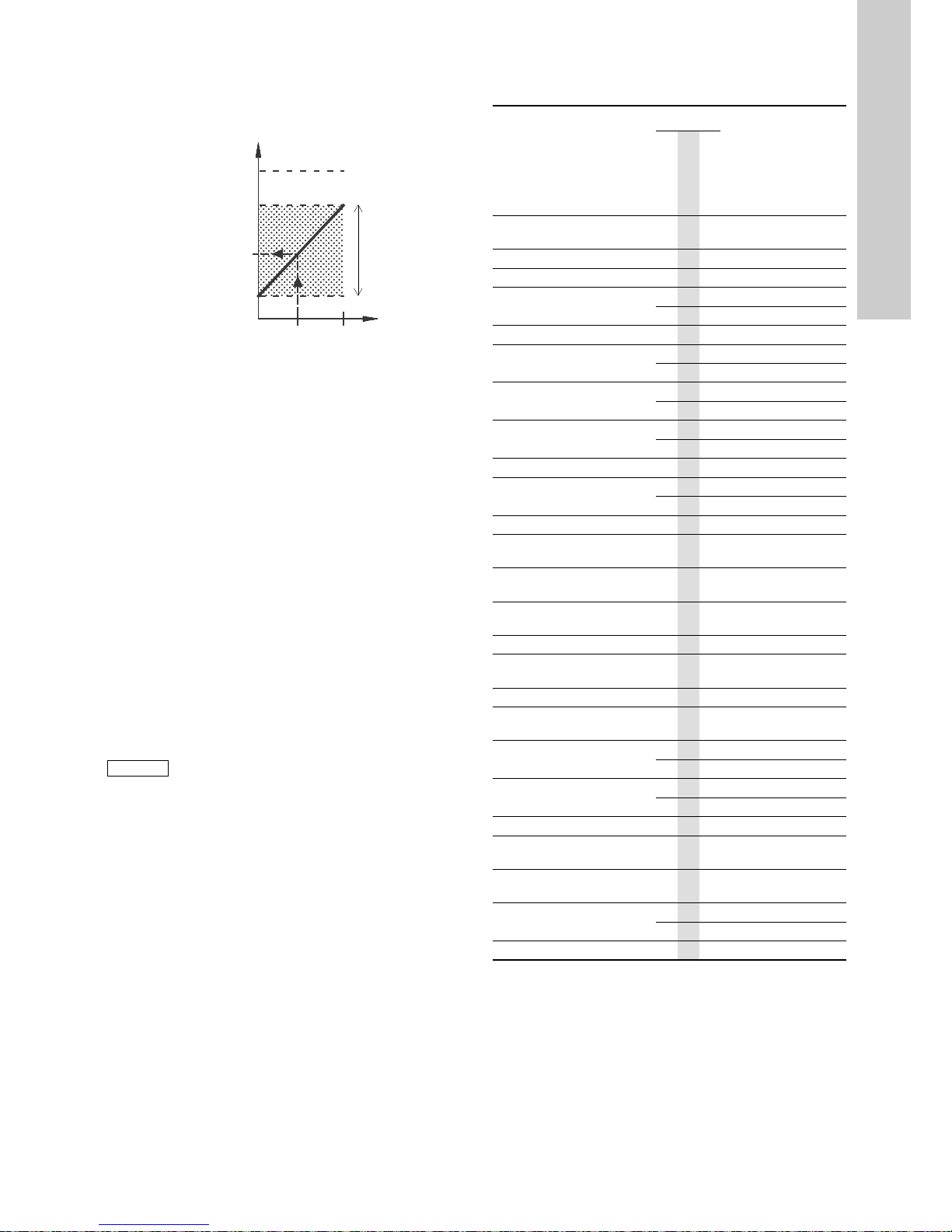
English (GB)
37
Proportional differential pressure
In "Proportional differential pressure" control mode, the actual
setpoint can be set externally within the range from 25 % of
maximum head to the setpoint set via the CUE menu. See fig. 40.
Fig. 40 Relation between the actual setpoint and the external
setpoint signal in "Proportional differential pressure"
control mode
Example: At a maximum head of 12 metres, a setpoint of 6
metres set via the CUE menu and an external setpoint of 40 %,
the actual setpoint will be as follows:
13.3 GENIbus signal
The CUE supports serial communication via an RS-485 input.
The communication is carried out according to the Grundfos
GENIbus protocol and enables connection to a building
management system or another external control system.
Operating parameters, such as setpoint and operating mode, can
be remote-set via the bus signal. At the same time, the pump can
provide status information about important parameters, such as
actual value of control parameter, input power and fault
indications.
Contact Grundfos for further details.
13.4 Other bus standards
Grundfos offers various bus solutions with communication
according to other standards.
Contact Grundfos for further details.
14. Maintenance and service
14.1 Cleaning the CUE
Keep the cooling fins and fan blades clean to ensure sufficient
cooling of the CUE.
14.2 Service parts and service kits
For further information on service parts and service kits, visit
www.grundfos.com > Grundfos Product Center.
15. Fault finding
15.1 Warning and alarm list
1)
In case of an alarm, the CUE will change the operating mode
depending on the pump type.
2)
AMA, Automatic Motor Adaptation. Not active in the present
software.
3)
Warning is reset in display 3.20.
TM03 8856 2607
Actual
setpoint
=
(setpoint, CUE menu - 25 % of maximum head)
x % external setpoint signal + 25 % of maximum
head
= (6 - 12 x 25 %) x 40 % + 12/4
=4.2 m
Note
If a bus signal is used, the number of settings
available via the CUE will be reduced.
Setpoint
90 % of max. head
Setpoint, CUE menu
25 % of max. head
Ext. setpoint signal
Actual setpoint
010 V
Actual
setpoint
range
Code and display text
Status
Operating
mode
Resetting
Warning
Alarm
Locked alarm
1
Too high leakage
current
● Stop Man.
2 Mains phase failure
● Stop Aut.
3 External fault
● Stop Man.
16 Other fault
● Stop Aut.
● Stop Man.
30 Replace motor bearings ●
- Man.
3)
32 Overvoltage
●
-Aut.
● Stop Aut.
40 Undervoltage
●
-Aut.
● Stop Aut.
48 Overload
● Stop Aut.
● Stop Man.
49 Overload
● Stop Aut.
55 Overload
●
-Aut.
● Stop Aut.
57 Dry running
● Stop Aut.
64
Too high CUE
temperature
● Stop Aut.
70
Too high motor
temperature
● Stop Aut.
77
Communication fault,
duty/standby
●
-Aut.
89 Sensor 1 outside range
●
1)
Aut.
91
Temperature sensor 1
outside range
●
-Aut.
93 Sensor 2 outside range ●
-Aut.
96
Setpoint signal outside
range
●
1)
Aut.
148
Too high bearing
temperature
●
-Aut.
● Stop Aut.
149
Too high bearing
temperature
●
-Aut.
● Stop Aut.
85 Inrush fault
● Stop Aut.
175
Temperature sensor 2
outside range
●
-Aut.
240
Relubricate motor
bearings
●
- Man.
3)
241 Motor phase failure
●
-Aut.
● Stop Aut.
242 AMA did not succeed
2)
● - Man.
Page 38

English (GB)
38
15.2 Resetting of alarms
In case of a fault or malfunction of the CUE, check the alarm list
in the "OPERATION" menu. The latest five alarms and latest five
warnings can be found in the log menus.
Contact a Grundfos technician if an alarm occurs repeatedly.
15.2.1 Warning
The CUE will continue the operation as long as the warning is
active. The warning remains active until the cause no longer
exists. Some warnings may switch to alarm condition.
15.2.2 Alarm
In case of an alarm, the CUE will stop the pump or change the
operating mode depending on the alarm type and pump type. See
section 15.1 Warning and alarm list.
Pump operation will be resumed when the cause of the alarm has
been remedied and the alarm has been reset.
Resetting an alarm manually
• Press [OK] in the alarm display.
• Press [On/Off] twice.
• Activate a digital input DI 2-DI 4 set to "Alarm reset" or the
digital input DI 1 (start/stop).
If it is not possible to reset an alarm, the reason may be that the
fault has not been remedied, or that the alarm has been locked.
15.2.3 Locked alarm
In case of a locked alarm, the CUE will stop the pump and
become locked. Pump operation cannot be resumed until the
cause of the locked alarm has been remedied and the alarm has
been reset.
Resetting a locked alarm
• Switch off the power supply to the CUE for about 30 seconds.
Switch on the power supply, and press OK in the alarm display
to reset the alarm.
15.3 Indicator lights
The table shows the function of the indicator lights.
15.4 Signal relays
The table shows the function of the signal relays.
See also fig. 18.
Indicator
light
Function
On (green)
The pump is running or has been stopped by a
stop function.
If flashing, the pump has been stopped by the
user (CUE menu), external start/stop or bus.
Off (orange)
The pump has been stopped with the on/off
button.
Alarm (red) Indicates an alarm or a warning.
Type Function
Relay 1
• Ready
•Alarm
• Operation
Pump running
Warning
Relubricate
Relay 2
• Ready
•Alarm
• Operation
Pump running
Warning
Relubricate
Page 39

English (GB)
39
16. Technical data
16.1 Enclosure
The individual CUE cabinet sizes are characterised by their
enclosures. The table shows the relationship of enclosure class
and enclosure type.
Example:
Read from the nameplate:
• Supply voltage = 3 x 380-500 V.
• Typical shaft power = 110 kW.
• Enclosure class = IP21.
The table shows that the CUE enclosure is D1h.
16.2 Main dimensions and weights
1)
The dimensions are maximum height, width and depth.
Typical shaft
power P2
Enclosure
3 x 380-500 V 3 x 525-690 V
[kW] [HP] IP21 IP54 IP21 IP54
110 80
D1h D1h
D1h D1h132 200
160 250
D2h D2h200 300
D2h D2h
250 350
TM05 9331 3713
Fig. 41 Enclosures D1h and D2h
Enclosure
Height [mm]
1)
Width [mm]
1)
Depth [mm]
1)
Screw holes [mm]
Weight [kg]
AaBb C c∅d ∅ef
D1h 901 844 325 180 378 20 11 11 25 62
D2h 1107 1051 420 280 378 20 11 11 25 125
Shipping dimensions
Enclosure Height [mm]
1)
Width [mm]
1)
Depth [mm]
1)
Weight [kg]
D1h 850 370 460 73 Only 3 x 380-500 V, 110 kW
D1h 850 370 460 72 - 124.5
D2h 1190 560 640 18 - 125.5
Page 40

English (GB)
40
16.3 Surroundings
16.4 Terminal torques
16.5 Cable length
16.6 Fuses and cable cross-section
16.6.1 Cable cross-section to signal terminals
16.6.2 Non-UL fuses and conductor cross-section to mains
and motor
1)
Screened motor cable, unscreened supply cable. AWG. See
section 16.6.3 UL fuses and conductor cross-section to mains
and motor.
16.6.3 UL fuses and conductor cross-section to mains and motor
1)
Screened motor cable, unscreened supply cable.
2)
American Wire Gauge.
Relative humidity 5-95 % RH
Ambient temperature Max. 45 °C
Average ambient temperature over 24 hours Max. 40 °C
Minimum ambient temperature at full
operation
0 °C
Minimum ambient temperature at reduced
operation
-10 °C
Temperature during storage and
transportation
-25 to 65 °C
Storage duration Max. 6 months
Maximum altitude above sea level without
performance reduction
1000 m
Maximum altitude above sea level with
performance reduction
3000 m
Note
The CUE comes in a packaging which is not suitable
for outdoor storage.
Screws M10 19-40 Nm
Screws M8 8.5 - 20.5 Nm
Maximum length, screened motor cable 80 m
Maximum length, unscreened motor cable 300 m
Maximum length, signal cable 300 m
Warning
Always comply with local regulations as to cable
cross-sections.
Maximum cable cross-section to signal
terminals, rigid conductor
1.5 mm
2
Maximum cable cross-section to signal
terminals, flexible conductor
1.0 mm
2
Minimum cable cross-section to signal
terminals
0.5 mm
2
Typical shaft
power P2
Maximum
fuse size
Fuse
type
Maximum conductor
cross-section
1)
[kW] [A]
[mm
2
]
3 x 380-500 V
110 300 gG 2 x 70
132 350 gG 2 x 70
160 400 gG 2 x 185
200 500 gG 2 x 185
250 600 gR 2 x 185
3 x 525-690 V
110 225 - 2 x 70
132 250 - 2 x 70
160 350 - 2 x 70
200 400 - 2 x 185
250 500 - 2 x 185
Typical shaft
power P2
Fuse type Maximum conductor
cross-section
1)
Bussmann
E1958
JFHR2
Bussmann
E4273
T/JDDZ
Bussmann
E4274
H/JDDZ
Bussmann
E125085
JFHR2
SIBA
E180276
RKI/JDDZ
Littel Fuse
E71611
JFHR2
Ferraz-Shawmut
E60314
JFHR2
[kW]
[AWG]
2)
3 x 380-500 V
110 FWH-300 JJS-300 NOS-300 170M3017 2028220-38 L50S-300 A50-P300 2 x 2/0
132 FWH-350 JJS-350 NOS-350 170M3018 2028220-38 L50S-350 A50-P350 2 x 2/0
160 FWH-400 JJS-400 NOS-400 170M4012 206xx32-400 L50S-400 A50-P400 2 x 350 MCM
200 FWH-500 JJS-500 NOS-500 170M4014 206xx32-500 L50S-500 A50-P500 2 x 350 MCM
250 FWH-600 JJS-600 NOS-600 170M4016 206xx32-600 L50S-600 A50-P600 2 x 350 MCM
----Bussmann
E125085
JFHR2
SIBA
E180276
JFHR2
- Ferraz-Shawmut
E76491
JFHR2
-
3 x 525-690 V
110 - - - 170M3017 2061032.38 - 6.6URD30D08A038 2 x 2/0
132 - - - 170M3018 2061032.350 - 6.6URD30D08A0350 2 x 2/0
160 - - - 170M4011 2061032.350 - 6.6URD30D08A0350 2 x 2/0
200 - - - 170M4012 2061032.400 - 6.6URD30D08A0400 2 x 350 MCM
250 - - - 170M4014 2061032.500 - 6.6URD30D08A0500 2 x 350 MCM
Page 41

English (GB)
41
16.7 Inputs and outputs
16.7.1 Mains supply (L1, L2, L3)
16.7.2 Motor output (U, V, W)
1)
Output voltage in % of supply voltage.
2)
Depending on the pump family selected.
16.7.3 RS-485 GENIbus connection
The RS-485 circuit is functionally separated from other central
circuits and galvanically separated from the supply voltage
(PELV).
16.7.4 Digital inputs
All digital inputs are galvanically separated from the supply
voltage (PELV) and other high-voltage terminals.
16.7.5 Signal relays
1)
IEC 60947, parts 4 and 5.
The relay contacts are galvanically separated from other circuits
by reinforced insulation (PELV).
16.7.6 Analog inputs
1)
The factory setting is voltage signal "U".
All analog inputs are galvanically separated from the supply
voltage (PELV) and other high-voltage terminals.
16.7.7 Analog output
The analog output is galvanically separated from the supply
voltage (PELV) and other high-voltage terminals.
16.7.8 MCB 114 sensor input module
16.8 Sound pressure level
The sound pressure of the CUE is measured at a distance of 1 m
from the unit.
The sound pressure level of a motor controlled by a frequency
converter may be higher than that of a corresponding motor
which is not controlled by a frequency converter. See section
6.7 RFI filters.
17. Disposal
This product or parts of it must be disposed of in an
environmentally sound way:
1. Use the public or private waste collection service.
2. If this is not possible, contact the nearest Grundfos company
or service workshop.
Subject to alterations.
Supply voltage 380-500 V ± 10 %
Supply voltage 525-690 V ± 10 %
Supply frequency 50/60 Hz
Maximum temporary imbalance between
phases
3 % of rated value
Leakage current to earth > 3.5 mA
Number of cut-ins, enclosure D Max. 1 time/2 min.
Note
Do not use the power supply for switching the CUE
on and off.
Output voltage 0-100 %
1)
Output frequency 0-100 Hz
2)
Switching on output Not recommended
Terminal number 68 (A), 69 (B), 61 GND (Y)
Terminal number 18, 19, 32, 33
Voltage level 0-24 VDC
Voltage level, open contact > 19 VDC
Voltage level, closed contact < 14 VDC
Maximum voltage on input 28 VDC
Input resistance, R
i
Approx. 4 kΩ
Relay 01, terminal number 1 (C), 2 (NO), 3 (NC)
Relay 02, terminal number 4 (C), 5 (NO), 6 (NC)
Maximum terminal load (AC-1)
1)
240 VAC, 2 A
Maximum terminal load (AC-8)
1)
240 VAC, 0.2 A
Maximum terminal load (DC-1)
1)
50 VDC, 1 A
Minimum terminal load
24 VDC 10 mA
24 VAC 20 mA
CCommon
NO Normally open
NC Normally closed
Analog input 1, terminal number 53
Voltage signal A53 = "U"
1)
Voltage range 0-10 V
Input resistance, R
i
Approx. 10 kΩ
Maximum voltage ± 20 V
Current signal A53 = "I"
1)
Current range 0-20, 4-20 mA
Input resistance, R
i
Approx. 200 Ω
Maximum current 30 mA
Maximum fault, terminals 53, 54 0.5 % of full scale
Analog input 2, terminal number 54
Current signal A54 = "I"
1)
Current range 0-20, 4-20 mA
Input resistance, R
i
Approx. 200 Ω
Maximum current 30 mA
Maximum fault, terminals 53, 54 0.5 % of full scale
Analog output 1, terminal number 42
Current range 0-20 mA
Maximum load to frame 500 Ω
Maximum fault 0.8 % of full scale
Analog input 3, terminal number 2
Current range 0/4-20 mA
Input resistance < 200 Ω
Analog inputs 4 and 5, terminal number 4, 5 and 7, 8
Signal type, 2- or 3-wire Pt100/Pt1000
Note
When using Pt100 with 3-wire cable, the resistance
must not exceed 30
Ω
.
Enclosure D1h: Maximum 76 dBA
Enclosure D2h: Maximum 74 dBA
Page 42
Declaration of conformity
42
Declaration of conformity 1
GB: EU declaration of conformity
We, Grundfos, declare under our sole responsibility that the product CUE,
to which the declaration below relates, is in conformity with the Council
Directives listed below on the approximation of the laws of the EU
member states.
— Low Voltage Directive (2014/35/EU).
Standard used: EN 61800-5-1:2007.
— EMC Directive (2014/30/EU).
Standard used: EN 61800-3:2004/A1:2012.
This EC/EU declaration of conformity is only valid when published as part
of the Grundfos installation and operating instructions (96783675)
Bjerringbro, 25th February 2016
Svend Aage Kaae
Director
Grundfos Holding A/S
Poul Due Jensens Vej 7
8850 Bjerringbro, Denmark
Person authorised to compile technical file and
empowered to sign the EC declaration of conformity.
Page 43

Grundfos companies
Argentina
Bombas GRUNDFOS de Argentina S.A.
Ruta Panamericana km. 37.500 Centro
Industrial Garin
1619 Garín Pcia. de B.A.
Phone: +54-3327 414 444
Telefax: +54-3327 45 3190
Australia
GRUNDFOS Pumps Pty. Ltd.
P.O. Box 2040
Regency Park
South Australia 5942
Phone: +61-8-8461-4611
Telefax: +61-8-8340 0155
Austria
GRUNDFOS Pumpen Vertrieb Ges.m.b.H.
Grundfosstraße 2
A-5082 Grödig/Salzburg
Tel.: +43-6246-883-0
Telefax: +43-6246-883-30
Belgium
N.V. GRUNDFOS Bellux S.A.
Boomsesteenweg 81-83
B-2630 Aartselaar
Tél.: +32-3-870 7300
Télécopie: +32-3-870 7301
Belarus
Представительство ГРУНДФОС в
Минске
220125, Минск
ул. Шафарнянская, 11, оф. 56, БЦ
«Порт»
Тел.: +7 (375 17) 286 39 72/73
Факс: +7 (375 17) 286 39 71
E-mail: minsk@grundfos.com
Bosnia and Herzegovina
GRUNDFOS Sarajevo
Zmaja od Bosne 7-7A,
BH-71000 Sarajevo
Phone: +387 33 592 480
Telefax: +387 33 590 465
www.ba.grundfos.com
e-mail: grundfos@bih.net.ba
Brazil
BOMBAS GRUNDFOS DO BRASIL
Av. Humberto de Alencar Castelo Branco,
630
CEP 09850 - 300
São Bernardo do Campo - SP
Phone: +55-11 4393 5533
Telefax: +55-11 4343 5015
Bulgaria
Grundfos Bulgaria EOOD
Slatina District
Iztochna Tangenta street no. 100
BG - 1592 Sofia
Tel. +359 2 49 22 200
Fax. +359 2 49 22 201
email: bulgaria@grundfos.bg
Canada
GRUNDFOS Canada Inc.
2941 Brighton Road
Oakville, Ontario
L6H 6C9
Phone: +1-905 829 9533
Telefax: +1-905 829 9512
China
GRUNDFOS Pumps (Shanghai) Co. Ltd.
10F The Hub, No. 33 Suhong Road
Minhang District
Shanghai 201106
PRC
Phone: +86 21 612 252 22
Telefax: +86 21 612 253 33
Croatia
GRUNDFOS CROATIA d.o.o.
Buzinski prilaz 38, Buzin
HR-10010 Zagreb
Phone: +385 1 6595 400
Telefax: +385 1 6595 499
www.hr.grundfos.com
GRUNDFOS Sales Czechia and
Slovakia s.r.o.
Čajkovského 21
779 00 Olomouc
Phone: +420-585-716 111
Denmark
GRUNDFOS DK A/S
Martin Bachs Vej 3
DK-8850 Bjerringbro
Tlf.: +45-87 50 50 50
Telefax: +45-87 50 51 51
E-mail: info_GDK@grundfos.com
www.grundfos.com/DK
Estonia
GRUNDFOS Pumps Eesti OÜ
Peterburi tee 92G
11415 Tallinn
Tel: + 372 606 1690
Fax: + 372 606 1691
Finland
OY GRUNDFOS Pumput AB
Trukkikuja 1
FI-01360 Vantaa
Phone: +358-(0) 207 889 500
France
Pompes GRUNDFOS Distribution S.A.
Parc d’Activités de Chesnes
57, rue de Malacombe
F-38290 St. Quentin Fallavier (Lyon)
Tél.: +33-4 74 82 15 15
Télécopie: +33-4 74 94 10 51
Germany
GRUNDFOS GMBH
Schlüterstr. 33
40699 Erkrath
Tel.: +49-(0) 211 929 69-0
Telefax: +49-(0) 211 929 69-3799
e-mail: infoservice@grundfos.de
Service in Deutschland:
e-mail: kundendienst@grundfos.de
Greece
GRUNDFOS Hellas A.E.B.E.
20th km. Athinon-Markopoulou Av.
P.O. B ox 7 1
GR-19002 Peania
Phone: +0030-210-66 83 400
Telefax: +0030-210-66 46 273
Hong Kong
GRUNDFOS Pumps (Hong Kong) Ltd.
Unit 1, Ground floor
Siu Wai Industrial Centre
29-33 Wing Hong Street &
68 King Lam Street, Cheung Sha Wan
Kowloon
Phone: +852-27861706 / 27861741
Telefax: +852-27858664
Hungary
GRUNDFOS Hungária Kft.
Park u. 8
H-2045 Törökbálint,
Phone: +36-23 511 110
Telefax: +36-23 511 111
India
GRUNDFOS Pumps India Private Limited
118 Old Mahabalipuram Road
Thoraipakkam
Chennai 600 096
Phone: +91-44 2496 6800
Indonesia
PT. GRUNDFOS POMPA
Graha Intirub Lt. 2 & 3
Jln. Cililitan Besar No.454. Makasar,
Jakarta Timur
ID-Jakarta 13650
Phone: +62 21-469-51900
Telefax: +62 21-460 6910 / 460 6901
Ireland
GRUNDFOS (Ireland) Ltd.
Unit A, Merrywell Business Park
Ballymount Road Lower
Dublin 12
Phone: +353-1-4089 800
Telefax: +353-1-4089 830
Italy
GRUNDFOS Pompe Italia S.r.l.
Via Gran Sasso 4
I-20060 Truccazzano (Milano)
Tel.: +39-02-95838112
Telefax: +39-02-95309290 / 95838461
Japan
GRUNDFOS Pumps K.K.
1-2-3, Shin-Miyakoda, Kita-ku,
Hamamatsu
431-2103 Japan
Phone: +81 53 428 4760
Telefax: +81 53 428 5005
Korea
GRUNDFOS Pumps Korea Ltd.
6th Floor, Aju Building 679-5
Yeoksam-dong, Kangnam-ku, 135-916
Seoul, Korea
Phone: +82-2-5317 600
Telefax: +82-2-5633 725
Latvia
SIA GRUNDFOS Pumps Latvia
Deglava biznesa centrs
Augusta Deglava ielā 60, LV-1035, Rīga,
Tālr.: + 371 714 9640, 7 149 641
Fakss: + 371 914 9646
Lithuania
GRUNDFOS Pumps UAB
Smolensko g. 6
LT-03201 Vilnius
Tel: + 370 52 395 430
Fax: + 370 52 395 431
Malaysia
GRUNDFOS Pumps Sdn. Bhd.
7 Jalan Peguam U1/25
Glenmarie Industrial Park
40150 Shah Alam
Selangor
Phone: +60-3-5569 2922
Telefax: +60-3-5569 2866
Mexico
Bombas GRUNDFOS de México S.A. de
C.V.
Boulevard TLC No. 15
Parque Industrial Stiva Aeropuerto
Apodaca, N.L. 66600
Phone: +52-81-8144 4000
Telefax: +52-81-8144 4010
Netherlands
GRUNDFOS Netherlands
Velu we zo om 3 5
1326 AE Almere
Postbus 22015
1302 CA ALMERE
Tel.: +31-88-478 6336
Telefax: +31-88-478 6332
E-mail: info_gnl@grundfos.com
New Zealand
GRUNDFOS Pumps NZ Ltd.
17 Beatrice Tinsley Crescent
North Harbour Industrial Estate
Albany, Auckland
Phone: +64-9-415 3240
Telefax: +64-9-415 3250
Norway
GRUNDFOS Pumper A/S
Strømsveien 344
Postboks 235, Leirdal
N-1011 Oslo
Tlf.: +47-22 90 47 00
Telefax: +47-22 32 21 50
Poland
GRUNDFOS Pompy Sp. z o.o.
ul. Klonowa 23
Baranowo k. Poznania
PL-62-081 Przeźmierowo
Tel: (+48-61) 650 13 00
Fax: (+48-61) 650 13 50
Portugal
Bombas GRUNDFOS Portugal, S.A.
Rua Calvet de Magalhães, 241
Apartado 1079
P-2770-153 Paço de Arcos
Tel.: +351-21-440 76 00
Telefax: +351-21-440 76 90
Romania
GRUNDFOS Pompe România SRL
Bd. Biruintei, nr 103
Pantelimon county Ilfov
Phone: +40 21 200 4100
Telefax: +40 21 200 4101
E-mail: romania@grundfos.ro
Russia
ООО Грун дф ос Россия
109544, г. Москва, ул. Школьная, 39-41,
стр. 1
Тел. (+7) 495 564-88-00 (495) 737-30-00
Факс (+7) 495 564 88 11
E-mail grundfos.moscow@grundfos.com
Serbia
Grundfos Srbija d.o.o.
Omladinskih brigada 90b
11070 Novi Beograd
Phone: +381 11 2258 740
Telefax: +381 11 2281 769
www.rs.grundfos.com
Singapore
GRUNDFOS (Singapore) Pte. Ltd.
25 Jalan Tukang
Singapore 619264
Phone: +65-6681 9688
Telefax: +65-6681 9689
Slovakia
GRUNDFOS s.r.o.
Prievozská 4D
821 09 BRATISLAVA
Phona: +421 2 5020 1426
sk.grundfos.com
Slovenia
GRUNDFOS LJUBLJANA, d.o.o.
Leskoškova 9e, 1122 Ljubljana
Phone: +386 (0) 1 568 06 10
Telefax: +386 (0)1 568 06 19
E-mail: tehnika-si@grundfos.com
South Africa
GRUNDFOS (PTY) LTD
Corner Mountjoy and George Allen Roads
Wilbart Ext. 2
Bedfordview 2008
Phone: (+27) 11 579 4800
Fax: (+27) 11 455 6066
E-mail: lsmart@grundfos.com
Spain
Bombas GRUNDFOS España S.A.
Camino de la Fuentecilla, s/n
E-28110 Algete (Madrid)
Tel.: +34-91-848 8800
Telefax: +34-91-628 0465
Sweden
GRUNDFOS AB
Box 333 (Lunnagårdsgatan 6)
431 24 Mölndal
Tel.: +46 31 332 23 000
Telefax: +46 31 331 94 60
Switzerland
GRUNDFOS Pumpen AG
Bruggacherstrasse 10
CH-8117 Fällanden/ZH
Tel.: +41-44-806 8111
Telefax: +41-44-806 8115
Taiwan
GRUNDFOS Pumps (Taiwan) Ltd.
7 Floor, 219 Min-Chuan Road
Taichung, Taiwan, R.O.C.
Phone: +886-4-2305 0868
Telefax: +886-4-2305 0878
Thailand
GRUNDFOS (Thailand) Ltd.
92 Chaloem Phrakiat Rama 9 Road,
Dokmai, Pravej, Bangkok 10250
Phone: +66-2-725 8999
Telefax: +66-2-725 8998
Turkey
GRUNDFOS POMPA San. ve Tic. Ltd. Sti.
Gebze Organize Sanayi Bölgesi
Ihsan dede Caddesi,
2. yol 200. Sokak No. 204
41490 Gebze/ Kocaeli
Phone: +90 - 262-679 7979
Telefax: +90 - 262-679 7905
E-mail: satis@grundfos.com
Ukraine
Бізнес Центр Європа
Столичне шосе, 103
м. Київ, 03131, Україна
Телеф он: (+38 044) 237 04 00
Факс.: (+38 044) 237 04 01
E-mail: ukraine@grundfos.com
United Arab Emirates
GRUNDFOS Gulf Distribution
P.O. Box 16768
Jebel Ali Free Zone
Dubai
Phone: +971 4 8815 166
Telefax: +971 4 8815 136
United Kingdom
GRUNDFOS Pumps Ltd.
Grovebury Road
Leighton Buzzard/Beds. LU7 4TL
Phone: +44-1525-850000
Telefax: +44-1525-850011
U.S.A.
GRUNDFOS Pumps Corporation
17100 West 118th Terrace
Olathe, Kansas 66061
Phone: +1-913-227-3400
Telefax: +1-913-227-3500
Uzbekistan
Grundfos Tashkent, Uzbekistan The Representative Office of Grundfos Kazakhstan in
Uzbekistan
38a, Oybek street, Tashkent
Телефон: (+998) 71 150 3290 / 71 150
3291
Факс: (+998) 71 150 3292
Addresses Revised 02.09.2016
Page 44

96783675 0916
ECM: 1187342
The name Grundfos, the Grundfos logo, and be think innovate are registered trademarks owned by Grundfos Holding A/S or Grundfos A/S, Denmark. All rights reserved worldwide. © Copyright Grundfos Holding A/S
www.grundfos.com
 Loading...