

Page 1
CU 300
Installation and operating instructions
No contact
Overvoltage
Undervoltage
Dry running
Speed reduction
Overtemperature
Overload
Sensor alarm
GRUNDFOS INSTRUCTIONS
Other languages
www.grundfos.com/CU300-manual
Page 2

English (GB) Installation and operating instructions
English (GB)
Original installation and operating instructions.
CONTENTS
Page
1. Symbols used in this document
2. General
2.1 Expansion possibilities
2.2 On/Off button
3. Mechanical installation
3.1 Location
3.2 Mounting CU 300
4. CU 300 as an alarm unit
4.1 Description
4.2 Electrical installation
4.3 Description of dry-running protection
4.4 Settings
4.5 Description of the dewatering function
5. CU 300 with constant-pressure control 0 to 6 bar
5.1 Description
5.2 Function
5.3 Positioning the pressure sensor
5.4 System sizing
5.5 Electrical installation
5.6 Startup
6. CU 300 with constant-pressure control 0 to 10 bar
6.1 Description
6.2 Function
6.3 Positioning the pressure sensor
6.4 System sizing
6.5 Electrical installation
6.6 Startup
7. CU 300 with constant-pressure control two-pump operation
7.1 Description
7.2 Function
7.3 Positioning the pressure sensor
7.4 System sizing
7.5 Electrical installation
7.6 Startup
8. CU 300 with sensors
8.1 General
8.2 Sensor functioning
8.3 Electrical installation
9. CU 300 connected to potentiometer
9.1 Description
9.2 Electrical installation
10. CU 300 connected to water meter
10.1 Description
10.2 Electrical installation
11. Constant water level
11.1 De scription
11.2 Function
2
11.3 Electrical installation
12. CU 300 connected to RS-485
12.1 Description
12.2 CU 300 connected to a PC directly
12.3 Electrical installation
3
13. Alarm functions
3
13.1 No contact
3
13.2 Overvoltage
3
13.3 Undervoltage
4
13.4 Dry running
4
13.5 Speed reduction
4
13.6 Overtemperature
4
13.7 Overload
4
13.8 Sensor alarm
5
14. CU 300 with Grundfos GO
6
14.1 Menu overview
6
15. Description of functions
7
15.1 Status
15.2 Settings
8
15.3 Alarms and warnings
8
16. Technical data
8
9
17. Disposal
9
10
11
12
12
12
13
13
14
15
16
16
16
17
17
18
19
20
20
21
22
24
24
25
26
26
27
28
28
28
Warning
Prior to installation, read these
installation and operating instructions.
Installation and operation must comply
with local regulations and accepted
codes of good practice.
Warning
This product can be used by children of
eight years and up and persons with
reduced physical, sensory or mental
capabilities or lack of experience and
knowledge if they are under
supervision or have been instructed in
the safe use of the product and
understand the hazards involved.
Children must not play with the
product. Cleaning and maintenance of
the product must not be made by
children without supervision.
29
31
31
31
32
34
34
34
35
35
36
36
37
37
37
38
40
40
40
45
46
47
Page 3

1. Symbols used in this document
Note
Green
Red
Warning
If these safety instructions are not
observed, it may result in personal
injury.
Notes or instructions that make the job
easier and ensure safe operation.
2. General
The control unit CU 300 is developed for the SQE
submersible pumps.
CU 300 covers the voltage range 1 x 100-240 V - 10
%/+ 6 %, 50/60 Hz, PE.
CU 300 has the following functions:
• control of the pump on the basis of sensor
signals
• setting of operating parameters
• monitoring of operation and alarm indication, if
any.
CU 300 indicates the following alarms:
• no contact
• overvoltage
• undervoltage
• dry running
• speed reduction
• overtemperature
• overload
• sensor alarm.
The individual alarms are described in details in
section 13. Alarm functions.
CU 300 receives alarm signals from the motor for the
following parameters:
• dry running
• incipient pump or motor defect
• too high temperature in motor electronics
• supply failure.
As standard, CU 300 incorporates an alarm signal
relay.
2.1 Expansion possibilities
CU 300 enables the use of the following devices:
• Grundfos GO:
Wireless infra-red remote control that enables
change of factory settings and monitoring of the
installation by calling up actual operating data,
e.g. speed, operating hours and power
consumption.
• External sensors:
Reception of data from external sensors and
control according to the data received, e.g. flow
rate, pressure, water level and conductivity.
• External potentiometer SPP 1:
Manual speed control.
2.2 On/Off button
By means of the On/Off button on CU 300, you can
do the following:
• Start or stop the pump.
• Reset alarms.
Fig. 1
The green and red indicator lights in the On/Off
button indicate pump operating condition as follows:
Indication Description
Green indicator light
permanently on
Green indicator light
flashing
Red indicator light
permanently on
Red indicator light
flashing
* If you use the On/Off button to stop the pump,
you must also use this button for restarting the
pump.
If you press the On/Off button for minimum 5
seconds, you start the pump, irrespective of any
active fault or alarm indications. When you
release the On/Off button, the pump will stop.
Pump is operating
Pump has been stopped by
one of the following:
• a sensor
• an external on/off switch
• a stop command from the
Grundfos GO
Pump has been stopped by
means of the On/Off button*
CU 300 is communicating
with the Grundfos GO
English (GB)
TM01 2829 4601
3
Page 4

3. Mechanical installation
104.5
104.5
100
140.5
English (GB)
Warning
Before starting any work on CU 300,
make sure that the power supply has
been switched off and that it cannot be
accidentally switched on.
3.1 Location
You can place CU 300 both indoors and outdoors.
The control unit must not be exposed to direct
sunlight.
3.2 Mounting CU 300
CU 300 is designed for wall mounting.
The box has six mounting holes (∅4). See fig. 2. The
dimensions are in mm.
CU 300 must be mounted as follows:
• Horizontally to allow condensed water, if any, to
escape. See fig. 2.
• On a plane surface to avoid deformation of the
box.
Fig. 2
CU 300 is supplied with a set of gaskets for the Pg
screwed connections.
The gaskets are to be used for the connection of
cables or wires to ensure tight connections, IP55,
and cable relief.
4. CU 300 as an alarm unit
4.1 Description
When CU 300 is connected to an SQE pump, one of
the eight red indicator lights on CU 300 will indicate
any alarm.
The indications are based on signals from the motor
and from sensors, if installed. The individual alarms
are described in details in section 13. Alarm
functions.
You can connect an external alarm-signal transmitter
and an external on/off switch. See section
4.2 Electrical installation concerning connection, etc.
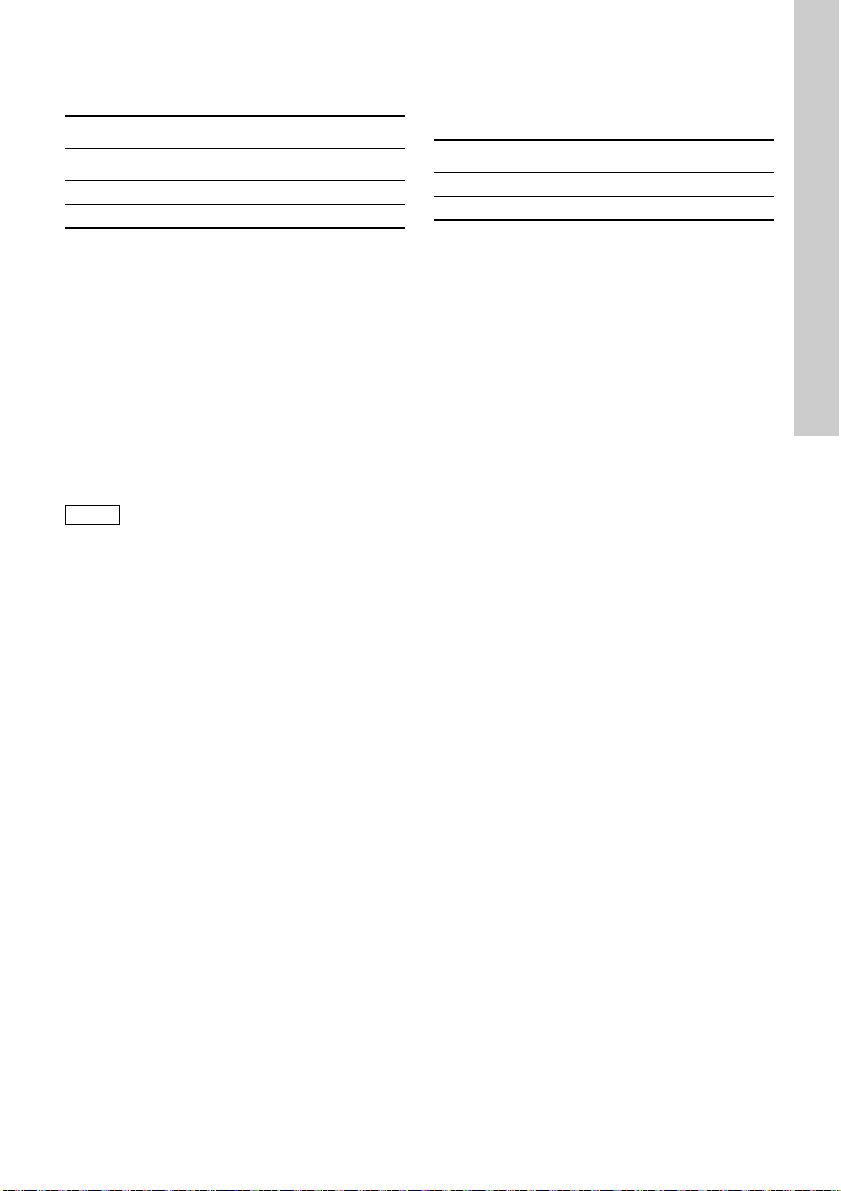
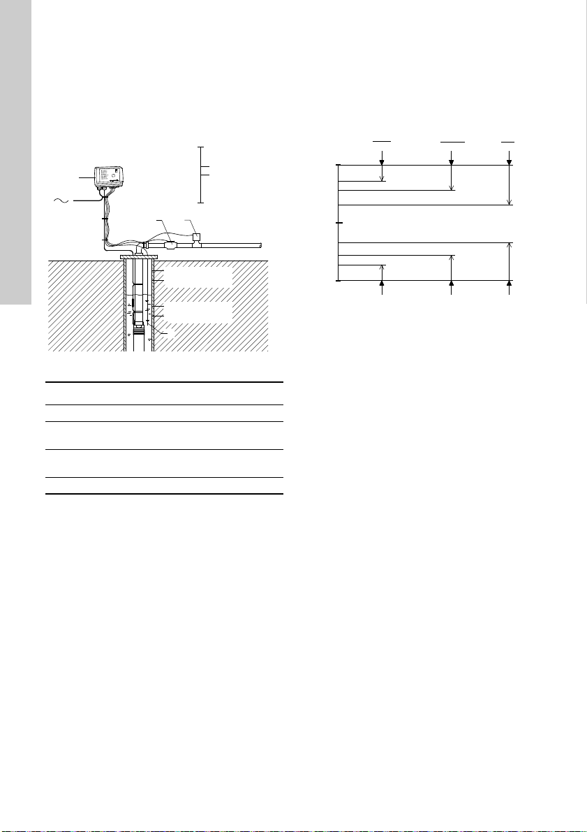
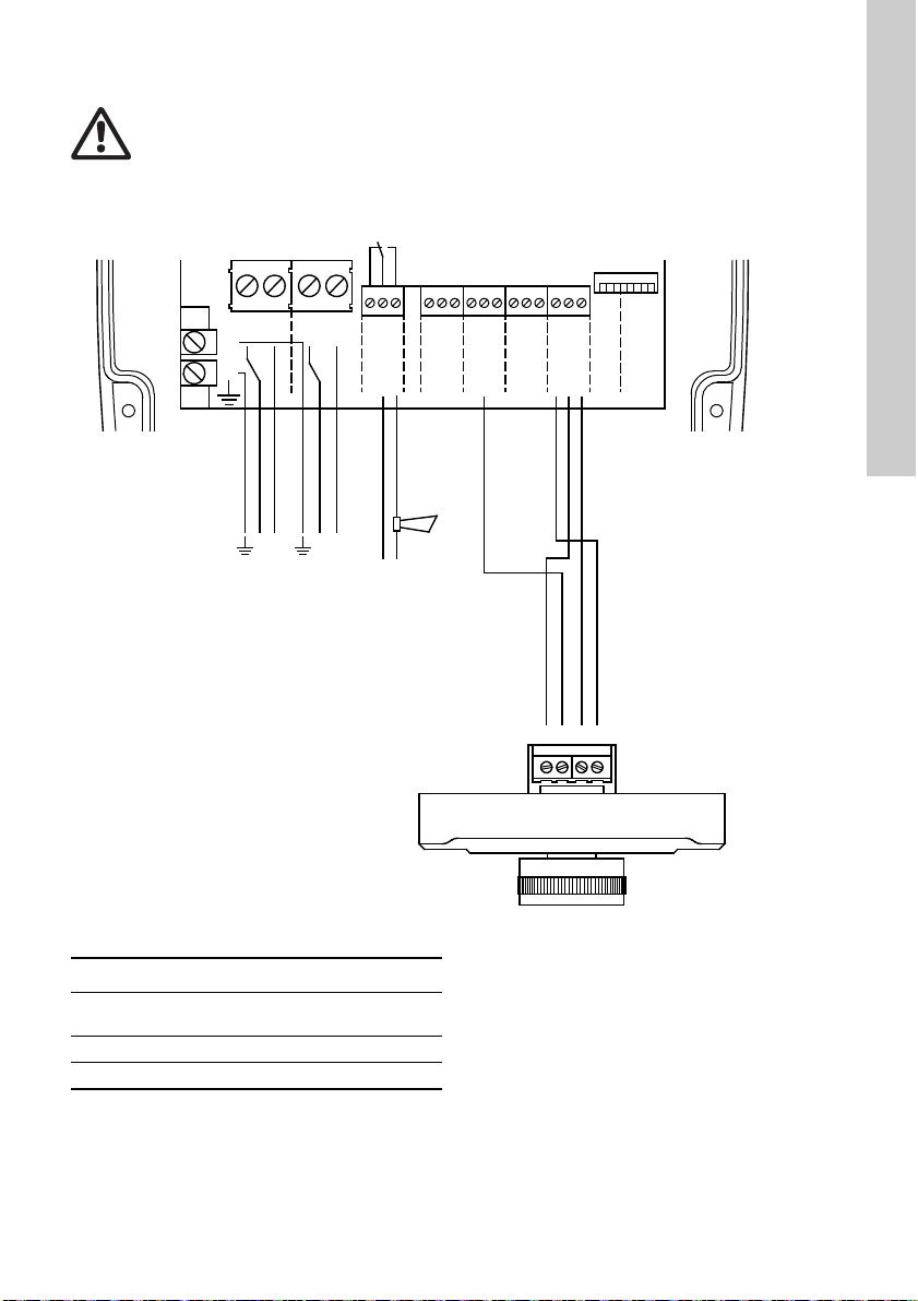
Figure 3 shows an example of an installation with CU
300 as an alarm unit.
Fig. 3
CU 300 functions as an alarm unit for the pump.
Furthermore, you can communicate with the pump
via the remote control Grundfos GO, see also
TM01 2824 2498
section 14. CU 300 with Grundfos GO.
TM01 3150 4601
4
Page 5

4.2 Electrical installation
K1
POWER
PE
PUMP
RELAY
ALARM
COM
NC
NO
NONCCOM
AUX
RELAY
IN
DIG
IN
+24VDC
GND
GND
+24VDC
IN
SENSOR
12
SENSOR
IN
+24VDC
GND
RS
485
RS
232
B
GND
ARIDTR
RXD
GND
567
12
1098
34
111213 161514 171819
PE
TXD
LNLN
H
S1
Note
Warning
Never make any connections in the CU 300 unit unless the power supply has been switched off.
CU 300 must be connected in accordance with the rules and standards in force for the
application in question.
The supply voltage and frequency are marked on the nameplate. Make sure that CU 300 is suitable for the
power supply on which it will be used.
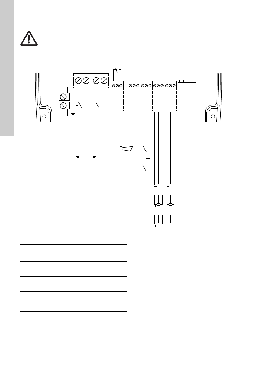
Fig. 4
Pos. Description
S1 On/off switch for start or stop of pump
H Alarm signal transmitter (optional)
Internal alarm signal relay
K1
Relay data: 250 VAC, 1 A, AC1
4.2.1 Mains supply
POWER, terminals 1, 2 and PE
Connect terminals 1 and 2 to the phase and neutral
leads of the mains supply. You can connect each
terminal to any of the two leads.
Connect the PE terminal to the green/yellow earth
lead. You must connect each PE terminal to an earth
lead of its own.
The maximum cross-section of the leads to be
connected is 6 mm
Backup fuse: Maximum 16 A.
2
.
You must not connect the leads of the
mains supply to terminals 3 and 4.
English (GB)
TM01 3067 3398
5
Page 6
4.2.2 Pump supply
Note
3000 min-1Max. speed
-1000 min
-1
Max.
speed as
set in
section
15.2.22
10,700 min
-1
Motor
speed
Watt
Pump power input
Pump power curve
Dry-running
power limit set
English (GB)
PUMP, terminals 3, 4 and PE
Connect terminals 3 and 4 to the phase and neutral
leads of the pump. You can connect each terminal to
any of the two leads.
Connect the PE terminal to the green/yellow earth
lead. You must connect each PE terminal to an earth
lead of its own.
The maximum cross-section of the leads to be
connected is 6 mm
2
.
4.2.3 Alarm signal relay
ALARM RELAY, terminals 5, 6 and 7
Connect terminals 5, 6 and 7 to the internal alarm
signal relay as follows:
• Terminal 5 NC (normally closed).
• Terminal 6 COM (common).
• Terminal 7 NO (normally open).
The relay is activated when the alarm and warning
limits are exceeded.
You can select manual or automatic restarting in the
Grundfos GO display "Automatic restarting".
Manual restarting is carried out by means of the On/
Off button on CU 300.
4.2.4 Digital input
DIG IN, terminals 11, 12 and 13
In fig. 4, the digital input is used to start and stop the
pump.
You can select the function of the digital input by
means of the Grundfos GO in the display "Digital
input".
4.3 Description of dry-running protection
When the pump sucks air, the pump power input
decreases.
If the pump power input falls below the dry-running
power limit set in the Grundfos GO display "Dryrunning stop", the pump will stop and CU 300 will
indicate the dry-running alarm.
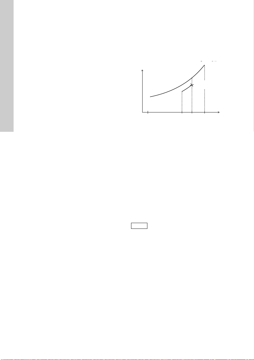
4.3.1 Function
The dry-running protection applies only if the motor
speed lies within the maximum speed range (i.e.
maximum speed less than 1000 min
Normally, maximum speed is 10,700 min
you can reduce the maximum speed in the Grundfos
GO display "Maximum speed". The dry-running
power limit set in the display "Dry-running stop" must
match the speed.
Changing the setpoint:
If you use the Grundfos GO display "Setpoint" or
"External setpoint" to change the setpoint, the pump
can be forced to run at a reduced speed in relation to
the maximum speed. The dry-running protection will
not protect the pump if the reduced speed lies
outside the maximum speed range (i.e. maximum
speed less 1000 min
6
-1
). See fig. 5.
-1
). See fig. 5.
-1
. However,
Constant-pressure control
In constant-pressure control mode, the dry-running
protection is active, as the motor will operate at
maximum speed in connection with dry running.
Pump power input curve
The curve shows the pump power input in relation to
the pump speed.
Fig. 5
4.4 Settings
For a detailed description of the Grundfos GO
displays, see section 14. CU 300 with Grundfos GO.
4.4.1 Required Grundfos GO settings
If the maximum speed of the pump has been
reduced by more than 1000 min
stop value must be changed. In order to change the
dry-running protection function, you must make the
following Grundfos GO settings.
1. Set "Dry-running protection" to "Active".
In certain installations, it may be
necessary to disable the dry-running
protection. The disabling applies to the
dry-running power limit set in the
display 15.2.21 Dry-running stop. See
fig. 5.
Set the dry-running power limit in the display
15.2.21 Dry-running stop by following the
procedure below:
– Start the pump against a closed discharge
pipe.
– Read the input power (P1) in the display
15.1.9 Power consumption.
– Calculate the dry-running power limit: P1 x 0.9
[W].
– Set this value in the display 15.2.21 Dry-
running stop.
-1
, the dry-running
TM01 2689 2598
Page 7

4.5 Description of the dewatering function
Note
35
1
125
60
60
Off time [minutes]
On time [minutes]
When the pump sucks air, the pump power input
decreases.
If the pump power input falls below the dry-running
power limit set in the display 15.2.21 Dry-running
stop, the pump will stop.
During dewatering, the green indicator light in the
On/Off button on CU 300 is flashing to indicate that
the pump has stopped.
4.5.1 Applications
You can use the dewatering function in applications
where the pump often runs dry, e.g.:
• In boreholes with a low yield.
• In boreholes and building sites where the water
table should be lowered.
4.5.2 Function
The dewatering function works as follows:
1. The pump is operating.
2. The pump sucks air due to a drop in the water
level.
3. The load decreases, and consequently the pump
power input does as well.
4. The pump stops when the power input falls to the
dry-running power limit set in the Grundfos GO
display 15.2.21 Dry-running stop.
The length of the stop time depends on
the setting you have made in the
Grundfos GO display "Dewatering max
off time". See section
15.2.19 Dewatering, maximum "On"
and "Off" time.
4.5.3 Required Grundfos GO settings
In order to activate the dewatering function, you
must make the following Grundfos GO settings:
1. Set "Dry-running protection" to "Active".
2. Set the dry-running power limit, i.e. dry-running
stop. See "Setting of dry-running power limit (dryrunning stop)" below.
3. Set the relation between run and stop times.
Indication of operation:
The dry-running alarm indication on CU 300 is
automatically disabled, when you make the
setting in the display 15.2.19 Dewatering,
maximum "On" and "Off" time.
To disable the dewatering function and return to
dry-running protection, simply disable the
"Dewatering" function in the display
15.2.18 Dewatering.
Setting of dry-running power limit (dr y-running
stop):
1. Start the pump against a closed discharge pipe.
2. Read the input power (P1) in the display
15.1.9 Power consumption.
3. Calculate the dry-running power limit: P1 x 0.9
[W].
4. Set this value in the display 15.2.21 Dry-running
stop.
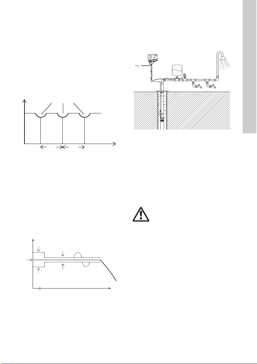
4.5.4 On/off times
The dewatering function means that there is a
dependence between the period of time during which
the pump is running, the on time, and the period of
time during which the pump is stopped, the off time.
Figure 6 shows an example of on and off times set in
the display 15.2.19 Dewatering, maximum "On" and
"Off" time.
Fig. 6
Explanation:
The on and off times are set to 60 minutes each. The
pump has been running for 25 minutes when dry
running occurs. The pump will be stopped for 35
minutes. If the pump has been running for e.g. 120
minutes, the stop time will be 1 minute.
English (GB)
TM06 3501 0415
7
Page 8

5. CU 300 with constant-pressure
Note
Note
Pressure
Low flow
High flow
Time
English (GB)
control - 0 to 6 bar
5.1 Description
Using constant-pressure control enables automatic
adjustment of the pump performance according to
consumption. The system maintains a constant
pressure within the maximum pump performance in
spite of a varying water consumption.
Figure 7 shows an example of an installation with
constant-pressure control within the range from 0 to
6 bar.
Fig. 7
Pos. Description
1CU 300
Diaphragm tank
2
Absorbs pressure variations.
Pressure sensor
3
The required pressure is set using the
Grundfos GO.
5.2 Function
The pressure is registered by means of the pressure
sensor, which transmits a signal to CU 300. CU 300
adjusts the pump performance accordingly by
changing the pump speed.
Mains borne signalling
The communication between CU 300 and the pump
is effected via the power supply cable.
This communication principle is called mains borne
signalling or power line communication. Using this
principle means that no additional cables to the
pump are required.
The communication of data is effected by means of a
high-frequency signal transmitted to the power
supply cable and led into the electronics unit by
means of signal coils incorporated in the motor and
CU 300 respectively.
When does the pump start?
The pump starts as a consequence of:
•high flow
• low pressure
• a combination of both.
To ensure that the pump is started when water is
consumed, a flow detection is required. The flow is
detected via pressure changes in the system. When
water is consumed, the pressure will drop
accordingly depending on the size of the diaphragm
tank and the water flow:
• At a low flow, the pressure will drop slowly.
• At a high flow, the pressure will drop quickly.
See fig. 8.
TM01 9649 4601
Fig. 8
When the pressure is dropping 0.1 bar/
s or faster, the pump will start
immediately.
If you use a diaphragm tank of 8 litres, the pump will
start at a flow rate of approx. 0.18 m
If a you use a larger tank, the flow must
be higher before the pump starts.
Consumption up to 0.18 m
The pump will start when the pressure has dropped
to 0.5 bar below the pressure setting.
The pump will run until the pressure is 0.5 bar above
the pressure set.
3
/h.
3
/h
TM01 8545 0400
8
Page 9
Flow detection
Pressure
Flow detection
Time10 s 10 s
A
Stop
Star t
Pressure
Controlling
Dynamic
variation
Flow
m
3
/h
0.18
12
8 l
CU 300
During pump operation, i.e. when water is
consumed, CU 300 will adjust the pump speed to
maintain a constant pressure. In order to stop the
pump when no water is consumed, CU 300 performs
flow detection every 10 seconds.
The pump speed is reduced until a small pressure
drop is registered. This pressure drop indicates that
water is consumed and the pump speed is resumed.
See fig. 9.
If the pump speed can be reduced without any
pressure drop being registered, this indicates that no
water is consumed. The diaphragm tank will be filled
with water and the pump will be stopped.
Fig. 9
System limits
Even though CU 300 is controlling the pressure
within ± 0.2 bar, bigger pressure variations may
occur in the system.
If the consumption is suddenly changed, e.g. if a tap
is opened, the water must start flowing before the
pressure can be made constant again. Such dynamic
variations depend on the pipework, but, typically,
they will lie between 0.5 and 1 bar.
If the desired consumption is higher than the quantity
the pump is able to deliver at the desired pressure,
the pressure follows the pump curve as illustrated in
fig. 10.
5.3 Positioning the pressure sensor
Pressure loss often causes inconvenience to the
user. CU 300 keeps the pressure constant in the
place where the pressure sensor is positioned. See
fig. 11.
Fig. 11
In fig.11, tap 1 is placed close to the pressure
sensor. Therefore, the pressure will be kept nearly
TM01 8546 0400TM01 8634 0500
constant at tap 1, as the friction loss is small. At the
shower and tap 2, the friction loss is bigger. This, of
course, depends on the piping. However, old and
furred-up piping may cause inconvenience due to
friction loss.
Therefore, we recommend that you position the
pressure sensor as close to the places of
consumption as possible.
5.4 System sizing
Warning
The installation must be designed for
the maximum pump pressure.
In normal installations with CU 300 and an SQE
pump set to constant-pressure control, the required
tank size is 8 litres. You can use bigger tanks without
causing any problems.
English (GB)
TM01 9670 4601
Fig. 10
A = Required pressure
9
Page 10

5.5 Electrical installation
K1
POWER
PE
PUMP
RELAY
ALARM
COM
NC
NO
NONCCOM
AUX
RELAY
IN
DIG
IN
+24VDC
GND
GND
+24VDC
IN
SENSOR
12
SENSOR
IN
+24VDC
GND
RS
485
RS
232
B
GND
ARIDTR
RXD
GND
567
12
1098
34
111213 161514 171819
PE
TXD
LNLN
H
1
3
2
4
English (GB)
Warning
Never make any connections in the CU 300 unit unless the power supply has been switched off.
CU 300 must be connected in accordance with the rules and standards in force for the
application in question.
The supply voltage and frequency are marked on the nameplate. Make sure that CU 300 is suitable for the
power supply on which it will be used.
Fig. 12
Pos. Description
1 Pressure sensor, brown lead, terminal 14
2 Pressure sensor, black lead, terminal 15
3 Pressure sensor, screen, terminal GND
Pressure sensor
4
Must be connected to analog input 1.
H Alarm signal transmitter (optional).
Internal alarm signal relay
K1
Relay data: 250 VAC, 1 A, AC1
10
TM01 9650 2400
Page 11

5.5.1 Mains supply
Note
POWER, terminals 1, 2 and PE
Connect terminals 1 and 2 to the phase and neutral
leads of the mains supply. You can connect each
terminal to any of the two leads.
Connect the PE terminal to the green/yellow earth
lead. You must connect each PE terminal to an earth
lead of its own.
Maximum cross-section of the leads to be connected
2
.
is 6 mm
Backup fuse: Maximum 16 A.
You must not connect the leads of the
mains supply to terminals 3 and 4.
5.5.2 Pump supply PUMP, terminals 3, 4 and PE
Connect terminals 3 and 4 to the phase and neutral
leads of the pump. You can connect each terminal to
any of the two leads.
Connect the PE terminal to the green/yellow earth
lead. You must connect each PE terminal to an earth
lead of its own.
Maximum cross-section of the leads to be connected
2
.
is 6 mm
5.5.3 Alarm signal relay ALARM RELAY, terminals 5, 6 and 7
Connect terminals 5, 6 and 7 to the internal alarm
signal relay as follows:
• Terminal 5 NC (normally closed).
• Terminal 6 COM (common).
• Terminal 7 NO (normally open).
The relay operates when the alarm and warning
limits are exceeded.
You can select manual or automatic restarting in the
Grundfos GO display "Automatic restarting".
Manual restarting is carried out by means of the On/
Off button on CU 300.
5.5.4 Required Grundfos GO settings
You must make the following Grundfos GO settings:
1. In display "Control mode" select "Closed loop".
2. Set the sensor in the "Analog input 1" or "Analog
input 2" display.
Example:
– sensor output signal (4-20 mA)
– setting range unit (m)
– setting range - head
min.: 0.0
max.: 40
3. Set the stop type in the "Stop type, sensor 1"
display.
– "Fill".
4. Set the digital input.
– "Not active"
5. Set the setpoint
Example: Desired head 35 m.
Rule: The maximum setting of the setpoint
corresponds to the maximum value set in display
15.2.4 Analog inputs less 5 m.
In this case, 40 less 5 = 35 m.
5.6 Startup
Prior to startup, the precharge pressure of the
diaphragm tank must be set to 70 % of the setpoint
set in the Grundfos GO display "Setpoint".
English (GB)
11
Page 12

6. CU 300 with constant-pressure
1
2
3
4
A
Stop (+ 0.5 bar)
Star t
(- 0.5 bar)
Pressure
Controlling
(± 0.2 bar)
Dynamic
(± 0.5 bar)
Flow
m
3
/h
0.18
English (GB)
control - 0 to 10 bar
6.1 Description
Using constant-pressure control enables automatic
adjustment of the pump performance according to
consumption. The system maintains a constant
pressure within the maximum pump performance in
spite of a varying water consumption.
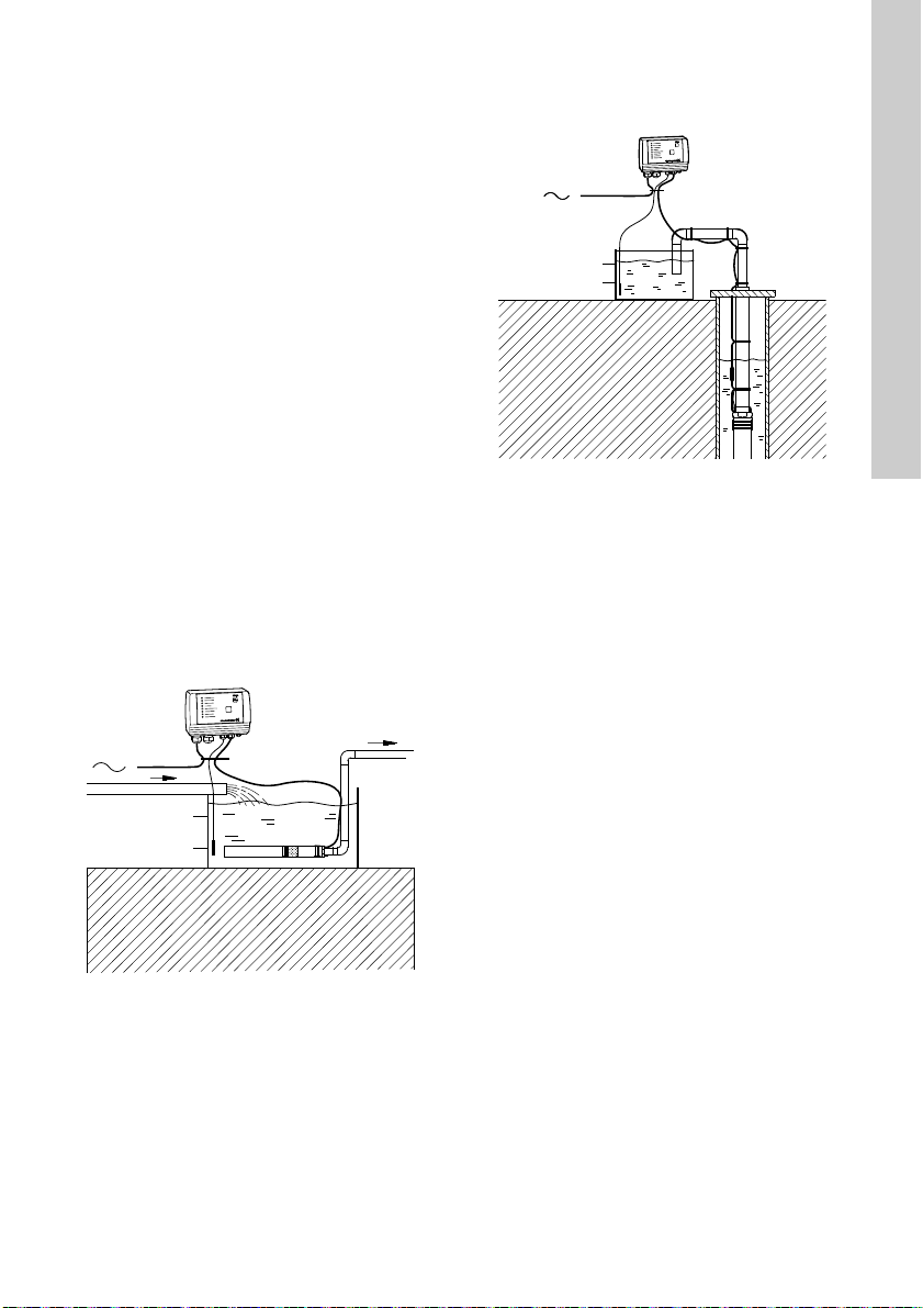
Figure 13 shows an example of an installation with
constant-pressure control within the range from 0 to
10 bar.
Fig. 13
Pos. Description
1CU 300
Diaphragm tank
2
Absorbs pressure variations.
Flow switch
3
The pump starts at once when water is
consumed at the taps.
Pressure sensor
4
The required pressure is set using the
Grundfos GO.
6.2 Function
The pressure is registered by means of the pressure
sensor and transmitted to CU 300. CU 300 adjusts
the pump performance accordingly. To ensure that
the pump is started when water is consumed, include
a flow switch in the system.
The required pressure (setpoint) is set in the
Grundfos GO display "Setpoint".
• Consumption up to 0.18 m
The flow switch contact is open.
The pump starts when the pressure is equal to
the setpoint less 0.5 bar. The pump will fill the
tank and stop when the pressure is equal to the
setpoint plus 0.5 bar. Consequently, the pump
runs on/off operation.
• Consumption above 0.18 m
The flow switch contact is closed.
The pump starts when the flow switch contact
closes and the speed control ensures that the
pressure is kept constant. If the flow is below
3
/h and the flow switch contact is opened,
0.18 m
the tank is filled to a pressure equal to the
setpoint plus 0.5 bar. When this pressure is
reached, the pump stops. Stopping is a
combination of the flow switch contact opening
and the pressure being equal to the setpoint plus
0.5 bar.
If the flow is larger than the quantity the pump is able
to deliver at the desired pressure, the pressure
follows the pump curve as illustrated in fig. 14.
TM01 2653 4601
Fig. 14
A = Required pressure
3
/h.
3
/h.
TM01 8634 0500
12
Page 13

6.3 Positioning the pressure sensor
1
2
CU 300
8 l
Pressure loss often causes inconvenience to the
user. CU 300 keeps the pressure constant in the
place where the pressure sensor is positioned. See
fig. 15.
Fig. 15
In fig. 15, tap 1 is placed close to the pressure
sensor. Therefore, the pressure will be kept nearly
constant at tap 1, as the friction loss is small. At the
shower and tap 2, the friction loss is bigger. This, of
course, depends on the piping. However, old and
furred-up piping may cause inconvenience due to
friction loss.
Therefore, we recommend that you position the
pressure sensor as close to the places of
consumption as possible.
6.4 System sizing
English (GB)
TM01 2834 4601
Warning
The installation must be designed for
the maximum pump pressure.
In normal installations with CU 300 and an SQE
pump set to constant-pressure control, the required
tank size is 8 litres. You can use bigger tanks without
causing any problems.
13
Page 14

6.5 Electrical installation
5
6
4
K1
POWER
PE
PUMP
RELAY
ALARM
COM
NC
NO
NONCCOM
AUX
RELAY
IN
DIG
IN
+24VDC
GND
GND
+24VDC
IN
SENSOR
12
SENSOR
IN
+24VDC
GND
RS
485
RS
232
B
GND
ARIDTR
RXD
GND
567
12
1098
34
1112 13 161514 17 1819
PE
TXD
LNLN
H
1
3
2
English (GB)
Warning
Never make any connections in the CU 300 unit unless the power supply has been switched off.
CU 300 must be connected in accordance with the rules and standards in force for the
application in question.
The supply voltage and frequency are marked on the nameplate. Make sure that CU 300 is suitable for the
power supply on which it will be used.
Fig. 16
Pos. Description
1 Pressure sensor, brown lead, terminal 14
2 Pressure sensor, black lead, terminal 15
3 Pressure sensor, screen, terminal GND
Pressure sensor
4
Must be connected to analog input 1.
5 Diaphragm tank connection
Flow switch
Must be connected to the digital input,
6
terminals 12 and 13. Cannot be connected
wrongly.
H Alarm signal transmitter (optional)
Internal alarm signal relay
K1
Relay data: 250 VAC, 1 A, AC1
14
TM01 3089 3398
Page 15

6.5.1 Mains supply
Note
POWER, terminals 1, 2 and PE
Connect terminals 1 and 2 to the phase and neutral
leads of the mains supply. You can connect each
terminal to any of the two leads.
Connect the PE terminal to the green/yellow earth
lead. You must connect each PE terminal to an earth
lead of its own.
Maximum cross-section of the leads to be connected
2
.
is 6 mm
Backup fuse: Maximum 16 A.
You must not connect the leads of the
mains supply to terminals 3 and 4.
6.5.2 Pump supply PUMP, terminals 3, 4 and PE
Connect terminals 3 and 4 to the phase and neutral
leads of the pump. You can connect each terminal to
any of the two leads.
Connect the PE terminal to the green/yellow earth
lead. You must connect each PE terminal to an earth
lead of its own.
Maximum cross-section of the leads to be connected
2
.
is 6 mm
6.5.3 Alarm signal relay ALARM RELAY, terminals 5, 6 and 7
Connect terminals 5, 6 and 7 to the internal alarm
signal relay as follows:
• Terminal 5 NC (normally closed).
• Terminal 6 COM (common).
• Terminal 7 NO (normally open).
The relay operates when the alarm and warning
limits are exceeded.
You can select manual or automatic restarting in the
Grundfos GO display "Automatic restarting".
Manual restarting is carried out by means of the On/
Off button on CU 300.
6.5.4 Required Grundfos GO settings
You must make the following Grundfos GO settings:
1. In display 15.2.2 Control mode" select "Closed
loop".
2. Set the sensor in the "Analog input 1" or "Analog
input 2" display.
Example:
– sensor output signal (4-20 mA)
– setting range unit (m)
– setting range - head
min.: 0.0
max.: 40.
3. Set the stop type in the "Stop type, sensor 1"
display.
– "Fill".
4. Set the digital input.
– "Not active"
5. Set the setpoint
Example: Desired head 35 m.
Rule: The maximum setting of the setpoint
corresponds to the maximum value set in display
"Analog input 1" less 5 m.
In this case, 40 less 5 = 35 m.
6.6 Startup
Prior to startup, the precharge pressure of the
diaphragm tank must be set to 70 % of the setpoint
set in the Grundfos GO display "Setpoint".
English (GB)
15
Page 16

7. CU 300 with constant-pressure
Note
1A
1B
2
3
4
English (GB)
control - two-pump operation
7.1 Description
Using constant-pressure control in connection with
two-pump operation enables automatic adjustment
of the pump performance according to the
consumption in systems where a high flow is
required. The system maintains a constant pressure
within the maximum pump performance in spite of a
varying water consumption.
During two-pump operation, the two
pumps must have the same nominal
flow, e.g. two SQE 2.
Figure 17 shows an example of a two-pump
installation with constant-pressure control.
Fig. 17
7.2 Function
The pressure is registered by means of the pressure
sensor and transmitted to CU 300 (master). CU 300
adjusts the pump speed to ensure that the pressure
is kept constant. To ensure that the pump connected
to CU 300 (master) is started when water is
consumed, a flow switch must be included in the
system.
Set CU 300 (master) to the desired pressure
(setpoint) in the Grundfos GO display "Setpoint".
• Consumption up to 0.18 m
The flow switch contact is open.
The pump connected to CU 300 (master) starts
when the pressure is equal to the setpoint less
0.5 bar. The pump will fill the tank and stop when
the pressure is equal to the setpoint plus 0.5 bar.
Consequently, the pump runs on/off operation.
• Consumption above 0.18 m
The flow switch contact is closed.
The pump connected to CU 300 (master) starts
when the flow switch contact closes and the
speed control ensures that the pressure is kept
constant.
If the flow is lower than 0.18 m
switch contact is opened, the tank is filled to a
pressure equal to the setpoint plus 0.5 bar. When
this pressure is reached, the pump stops.
Stopping is a combination of the flow switch
contact opening and the pressure being equal to
the setpoint plus 0.5 bar.
If the consumption exceeds the quantity the
pump connected to CU 300 (master) is able to
deliver, the pressure in the diaphragm tank will
fall.
TM01 2654 4601
3
/h.
3
/h.
3
/h and the flow
Pos. Description
1A, 1B
1A = CU 300 (master)
1B = CU 300 (slave)
Diaphragm tank, minimum 24 litres
2
Absorbs pressure variations.
Flow switch
3
The pump starts at once when water is
consumed at the taps.
Pressure sensor
4
The required pressure is set using the
Grundfos GO.
16
Page 17

The pump connected to CU 300 (slave) will be
A
Stop (+ 0.5 bar)
Start
(- 0.5 bar)
Pressure
Controlling
(± 0.2 bar)
Dynamic
(± 1.0 bar)
Flow
m
3
/h
0.18
started in the two following situations:
1. If the pressure in the diaphragm tank falls to 1
bar below the setpoint.
2. If the pump connected to CU 300 (master) has
been operating at maximum performance for
more than 5 seconds and the water requirement
has increased.
The pump connected to CU 300 (slave) will be
stopped in the three following situations:
1. If the system pressure is 1 bar higher than the
setpoint.
2. If the pump connected to CU 300 (master) has
been operating at minimum performance for
more than 5 seconds and the water requirement
has fallen.
3. If the flow switch indicates "No flow" and the
system pressure is 0.5 bar higher than the
setpoint.
If the flow is larger than the quantity the pumps are
able to deliver at the desired pressure, the pressure
follows the pump curve. See fig. 18.
7.3 Positioning the pressure sensor
See section 6.3 Positioning the pressure sensor.
7.4 System sizing
Warning
The installation must be designed for
the maximum pump pressure.
In two-pump installations set for constant-pressure
control, the required tank size is 24 litres. You can
use bigger tanks without any problems.
English (GB)
A = Required pressure
Fig. 18
TM01 8634 0500
17
Page 18

7.5 Electrical installation
K1
POWER
PE
PUMP
RELAY
ALARM
COM
NC
NO
NONCCOM
AUX
RELAY
IN
DIG
IN
+24VDC
GND
GND
+24VDC
IN
SENSOR
12
SENSOR
IN
+24VDC
GND
RS
485
RS
232
B
GND
ARIDTR
RXD
GND
567
12
109834111213 161514 171819
PE
TXD
LNLN
1
3
2
NLNL
TXD
PE
191817141516131211438910
21
765
GND
RXD
DTRRIA
GND
B
232
RS
485
RS
GND
+24VDC
IN
SENSOR
21
SENSOR
IN
+24VDC
GND
GND
+24VDC
IN
DIG
IN
RELAY
AUX
COMNCNO
NO
NC
COM
ALARM
RELAY
PUMP
PE
POWER
A
B
5
6
4
D
C
5
4
7
English (GB)
Warning
Never make any connections in the CU 300 unit unless the power supply has been switched off.
CU 300 must be connected in accordance with the rules and standards in force for the
application in question.
The supply voltage and frequency are marked on the nameplate. Make sure that CU 300 is suitable for the
power supply on which it will be used.
Fig. 19
TM01 9671 2500
Pos. Description
A CU 300 (master)
B CU 300 (slave)
3
/h
3
/h
3
/h)
3
/h)
C Installation for Q < 5 m
D Installation for Q > 5 m
1 Pressure sensor, brown lead, terminal 14
2 Pressure sensor, black lead, terminal 15
3 Pressure sensor, screen, terminal GND
4
5 Diaphragm tank connection
6
7
K1
Pressure sensor
Must be connected to analog input 1.
Flow switch (Q < 5 m
Must be connected to the digital input,
terminals 12 and 13. Cannot be connected
wrongly.
Flow switch (Q > 5 m
Must be connected to the digital input,
terminals 12 and 13. Cannot be connected
wrongly.
Internal alarm signal relay
Relay data: 250 VAC, 1 A, AC1
18
Page 19
7.5.1 Auxiliary relay
Note
Connect CU 300 (master) to CU 300 (slave) as
follows:
Connections
CU 300 (master) CU 300 (slave)
Terminal 9 (COM) Terminal 12 (IN)
Terminal 10 (NO) Terminal 13 (GND)
See fig. 19.
7.5.2 Mains supply
POWER, terminals 1, 2 and PE
Connect terminals 1 and 2 to the phase and neutral
leads of the mains supply. See fig. 19.
You can connect each terminal to any of the two
leads.
Connect the PE terminal to the green/yellow earth
lead. You must connect each PE terminal to an earth
lead of its own.
Maximum cross-section of the leads to be connected
2
.
is 6 mm
Backup fuse: Maximum 16 A.
You must not connect the leads of the
mains supply to terminals 3 and 4.
7.5.3 Pump supply
PUMP, terminals 3, 4 and PE
Connect terminals 3 and 4 to the phase and neutral
leads of the pump. See fig. 19.
You can connect each terminal to any of the two
leads.
Connect the PE terminal to the green/yellow earth
lead. You must connect each PE terminal to an earth
lead of its own.
Maximum cross-section of the leads to be connected
2
.
is 6 mm
7.5.4 Alarm signal relay
ALARM RELAY, terminals 5, 6 and 7
Connect terminals 5, 6 and 7 to the internal alarm
signal relay as follows:
• Terminal 5 NC (normally closed).
• Terminal 6 COM (common).
• Terminal 7 NO (normally open).
The relay operates when the alarm and warning
limits are exceeded.
You can select manual or automatic restarting in the
Grundfos GO display "Automatic restarting".
Manual restarting is carried out by means of the On/
Off button on CU 300.
7.5.5 Flow switch and pressure sensor
Connect the flow switch and the pressure sensor to
the control unit (A = master) as illustrated in fig. 19.
Flow switch:
Pump type Product number
SQE 1 96037332
SQE 2, SQE 3, SQE 5, SQE 7 96037559
7.5.6 Required Grundfos GO settings
You must make the following Grundfos GO settings
on CU 300 (master):
1. In display "Control mode" select "Closed loop".
2. Set the sensor in the "Analog input 1" or "Analog
input 2" display.
Example:
– sensor output signal (4-20 mA)
– setting range unit (m)
– setting range - head
min.: 0.0
max.: 40.
3. Set the stop type in the "Stop type, sensor 1"
display.
– "Fill".
4. Set the digital input in "Digital input 1" display:
– "Start".
5. Set the setpoint
Example: Desired head 35 m.
Rule: The maximum setting of the setpoint
corresponds to the maximum value set in display
15.2.4 Analog inputs less 5 m.
In this case, 40 less 5 = 35 m.
You must make the following Grundfos GO setting on
CU 300 (slave):
6. Set the digital input in "Digital input 1" display:
– "Start"
7.6 Startup
Prior to startup, you must set the precharge pressure
of the diaphragm tank to 70 % of the setpoint set in
the Grundfos GO display "Setpoint".
English (GB)
19
Page 20
8. CU 300 with sensors
pH
100%
0
2
1
3
4
Alarm
Warning
Warning
Warning
Max. (start)
Min. (stop)
Max.
Max.
Max.
Min.
Min.
Min.
Status
100%
Sensor signal
0
Stop
Warning
Alarm
English (GB)
8.1 General
CU 300 can be used in systems with one to three
sensors connected.
Figure 20 shows an example of an installation
incorporating sensors.
Fig. 20
Pos. Description
1 CU 300
pH sensor
2
Detects the water quality.
Pulse flow meter
3
Detects the water quantity.
4 Level sensor
You can set the alarm, warning and stop limits
individually for all sensors connected. The limit
settings do not influence each other, and each
setting offers its own functioning.
Figure 21 shows a schematic presentation of the
setting of maximum and minimum limits for alarm,
warning and stop respectively.
Fig. 21
You must only set the limits applying to the selected
sensor.
TM01 2672 4601
These settings are made in the displays
15.2.4 Analog inputs and 15.2.5 Limits, sensor 1 and
2 to 15.2.5 Limits, sensor 1 and 2.
TM01 2697 2298
20
Page 21
8.2 Sensor functioning
Max. (start)
Min. (stop)
Max. (stop)
Min. (start)
8.2.1 Alarm limits
When an alarm limit is exceeded, the following takes
place:
1. The pump is stopped.
2. The alarm signal relay operates.
3. The "Sensor alarm" indicator light on CU 300 is
on.
4. The alarm appears in the Grundfos GO display
"Alarms and warnings".
If the pump has stopped already or if the alarm
signal relay has operated, this condition is
maintained.
8.2.2 Warning limits
When a warning limit is exceeded, the following
takes place:
1. The alarm signal relay operates.
2. Pump operation is continued. No "Sensor alarm"
indication.
3. The warning appears in the Grundfos GO display
"Alarms and warnings".
8.2.3 Start and stop limits
Start and stop limits must be used in connection with
the emptying and filling of e.g. water tanks.
The start and stop function depends on the
application, i.e. emptying or filling.
• Emptying means that the pump must start at a
given maximum water level and stop at a given
minimum water level. See fig. 22.
• Filling means that the pump must start at a given
minimum water level and stop at a given
maximum water level. See fig. 23.
Fig. 23
English (GB)
TM01 2699 4601
Fig. 22
TM01 2700 4601
21
Page 22
8.3 Electrical installation
K1
POWER
PE
PUMP
RELAY
ALARM
COM
NC
NO
NONCCOM
AUX
RELAY
IN
DIG
IN
+24VDC
GND
GND
+24VDC
IN
SENSOR
12
SENSOR
IN
+24VDC
GND
RS
485
RS
232
B
GND
ARIDTR
RXD
GND
567
12
1098
34
111213 161514 171819
PE
TXD
LNLN
H
D1
4-20 mA
D1
A1
A2
0-20 mA
0-10V/2-10V
A3
English (GB)
Warning
Never make any connections in the CU 300 unit unless the power supply has been switched off.
CU 300 must be connected in accordance with the rules and standards in force for the
application in question.
The supply voltage and frequency are marked on the nameplate. Make sure that CU 300 is suitable for the
power supply on which it will be used.
Fig. 24
Pos. Description
A1 Analog sensor, output signal 4-20 mA
A2 Analog sensor, output signal 0-20 mA
A3 Analog sensor, output signal 0-10/2-10 V
D1 Digital sensor, NO (normally open)
D1 Digital sensor, NC (normally closed)
H Alarm signal transmitter (optional)
Internal alarm signal relay
K1
Relay data: 250 VAC, 1 A, AC1
22
TM01 3088 2500
Page 23

8.3.1 Mains supply
Note
POWER, terminals 1, 2 and PE
Connect terminals 1 and 2 to the phase and neutral
leads of the mains supply. You can connect each
terminal to any of the two leads.
Connect the PE terminal to the green/yellow earth
lead. You must connect each PE terminal to an earth
lead of its own.
Maximum cross-section of the leads to be connected
2
.
is 6 mm
Backup fuse: Maximum 16 A.
You must not connect the leads of the
mains supply to terminals 3 and 4.
8.3.2 Pump supply PUMP, terminals 3, 4 and PE
Connect terminals 3 and 4 to the phase and neutral
leads of the pump. You can connect each terminal to
any of the two leads.
Connect the PE terminal to the green/yellow earth
lead. You must connect each PE terminal to an earth
lead of its own.
Maximum cross-section of the leads to be connected
2
.
is 6 mm
8.3.3 Alarm signal relay ALARM RELAY, terminals 5, 6 and 7
Connect terminals 5, 6 and 7 to the internal alarm
signal relay as follows:
• Terminal 5 NC (normally closed).
• Terminal 6 COM (common).
• Terminal 7 NO (normally open).
The relay operates when the alarm and warning
limits are exceeded.
You can select manual or automatic restarting in the
Grundfos GO display "Automatic restarting".
Manual restarting is carried out by means of the On/
Off button on CU 300.
8.3.4 Sensors
SENSOR 1 and SENSOR 2, terminals 14, 15, 16,
17, 18 and 19:
Terminals 14, 15 and 16 (SENSOR 1) and terminals
17, 18 and 19 (SENSOR 2) are used for external
sensors, e.g. a pressure gauge, a flow meter or
another type of sensor.
You set the limits for the signal from an external
sensor in the Grundfos GO in the "Analog input 1"
and "Analog input 2" displays.
You can use the signal to do the following:
• To start and stop the motor.
• To operate the alarm signal relay, without
stopping the motor.
The sensors must give signals within the ranges
0-20 or 4-20 mA, 0-10 or 2-10 VDC. Changeover
between current and voltage signals is carried out by
means of the Grundfos GO.
The total load of terminals 11, 14 and 17 (+24 VDC)
must not exceed 100 mA.
8.3.5 Required Grundfos GO settings
You must make the following Grundfos GO settings:
1. Set "Analog input 1".
– sensor output signal (4-20 mA)
– setting range unit (m)
– setting range - head min.: 0.0
max.: 50.
2. Set "Analog input 2" to "Not active".
3. Set the minimum stop value for sensor 1 in
display "Min. stop value, sensor 1".
4. Set the maximum stop value for sensor 1 in
display "Max. stop value, sensor 1".
5. Set the "Warning limits" and "Alarm limits" for
sensor 1 in display "Limits, sensor 1".
6. Set the desired stop type in display "Stop type,
sensor 1:
Example:
– "Fill".
English (GB)
23
Page 24
9. CU 300 connected to potentiometer
Note
1
2
3
English (GB)
9.1 Description
Using an external potentiometer enables:
• Manual control of the motor speed, and thereby
of pump performance.
Manual starting/stopping of the pump.
To stop the pump, turn the
potentiometer (SPP 1) to "STOP".
Figure 25 shows an example of an installation with a
potentiometer.
Fig. 25
Pos. Description
1CU 300
External Grundfos potentiometer, SPP 1
The required flow is obtained by changing
2
the motor speed manually using the
external potentiometer.
3 Water tank
TM01 2660 4601
24
Page 25
9.2 Electrical installation
K1
POWER
PE
PUMP
RELAY
ALARM
COM
NC
NO
NONCCOM
AUX
RELAY
IN
DIG
IN
+24VDC
GND
GND
+24VDC
IN
SENSOR
12
SENSOR
IN
+24VDC
GND
RS
485
RS
232
B
GND
ARIDTR
RXD
GND
567
12
1098
34
111213 161514 171819
PE
TXD
LNLN
H
4
3
21
SPP 1
SENSOR IN
GND
DIG IN
+24 VDC
Warning
Never make any connections in the CU 300 unit unless the power supply has been switched off.
CU 300 must be connected in accordance with the rules and standards in force for the
application in question.
The supply voltage and frequency are marked on the nameplate. Make sure that CU 300 is suitable for the
power supply on which it will be used.
English (GB)
Fig. 26
Pos. Description
Internal alarm signal relay
K1
Relay data: 250 VAC, 1 A, AC1
H Alarm signal transmitter (optional)
SPP 1 External Grundfos potentiometer, SPP 1
TM01 3091 3398
25
Page 26

9.2.1 Mains supply
Note
1
2
English (GB)
POWER, terminals 1, 2 and PE
Connect terminals 1 and 2 to the phase and neutral
leads of the mains supply. You can connect each
terminal to any of the two leads.
Connect the PE terminal to the green/yellow earth
lead. You must connect each PE terminal to an earth
lead of its own.
Maximum cross-section of the leads to be connected
2
.
is 6 mm
Backup fuse: Maximum 16 A.
You must not connect the leads of the
mains supply to terminals 3 and 4.
9.2.2 Pump supply
PUMP, terminals 3, 4 and PE
Connect terminals 3 and 4 to the phase and neutral
leads of the pump. You can connect each terminal to
any of the two leads.
Connect the PE terminal to the green/yellow earth
lead. You must connect each PE terminal to an earth
lead of its own.
Maximum cross-section of the leads to be connected
2
.
is 6 mm
9.2.3 Alarm signal relay
ALARM RELAY, terminals 5, 6 and 7
Connect terminals 5, 6 and 7 to the internal alarm
signal relay as follows:
• Terminal 5 NC (normally closed).
• Terminal 6 COM (common).
• Terminal 7 NO (normally open).
The relay operates when the alarm and warning
limits are exceeded.
You can select manual or automatic restarting in the
Grundfos GO display "Automatic restarting".
Manual restarting is carried out by means of the On/
Off button on CU 300.
9.2.4 Potentiometer SPP 1
Connections between the SPP 1 and CU 300:
9.2.5 Required Grundfos GO settings
You must make the following Grundfos GO settings:
1. In display "Control mode" select "Open loop".
2. Set the external setpoint to "SPP 1", enabling
speed control using the SPP 1. "Analog input 2"
is set to "SPP 1".
3. Set "Digital input 1" to "Start"
10. CU 300 connected to water meter
10.1 Description
Using a water meter (pulse flow meter) enables:
• Monitoring of the flow.
• Stop of pump after a given quantity of water has
been pumped.
• Indication of accumulated flow and the energy
consumption required to pump 1 m
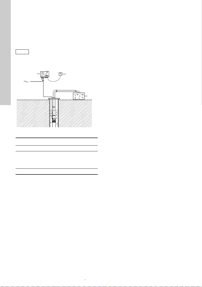
Figure 27 shows an example of an irrigation system
incorporating a water meter.
Fig. 27
Pos. Description
1CU 300
2 Water meter (pulse flow meter)
3
.
TM01 2659 4601
SPP 1 CU 300
1 17 (SENSOR 2 +24 VDC)
2 19 (SENSOR 2 GND)
3 12 (DIG IN)
4 18 (SENSOR 2 IN)
26
Page 27

10.2 Electrical installation
D1
K1
POWER
PE
PUMP
RELAY
ALARM
COM
NC
NO
NONCCOM
AUX
RELAY
IN
DIG
IN
+24VDC
GND
GND
+24VDC
IN
SENSOR
12
SENSOR
IN
+24VDC
GND
RS
485
RS
232
B
GND
ARIDTR
RXD
GND
567
12
1098
34
111213 161514 171819
PE
TXD
LNLN
H
Note
Warning
Never make any connections in the CU 300 unit unless the power supply has been switched off.
CU 300 must be connected in accordance with the rules and standards in force for the
application in question.
The supply voltage and frequency are marked on the nameplate. Make sure that CU 300 is suitable for the
power supply on which it will be used.
Fig. 28
English (GB)
TM01 6223 1899
Pos. Description
D1 Water meter (pulse flow meter)
H Alarm signal transmitter (optional)
Internal alarm signal relay
K1
Relay data: 250 VAC, 1 A, AC1
10.2.1 Mains supply POWER, terminals 1, 2 and PE
Connect terminals 1 and 2 to the phase and neutral
leads of the mains supply. You can connect each
terminal to any of the two leads.
Connect the PE terminal to the green/yellow earth
lead. You must connect each PE terminal to an earth
lead of its own.
Maximum cross-section of the leads to be connected
is 6 mm
2
.
Backup fuse: Maximum 16 A.
You must not connect the leads of the
mains supply to terminals 3 and 4.
27
Page 28

10.2.2 Pump supply
1
2
Warning
Desired level
Warning
English (GB)
PUMP, terminals 3, 4 and PE
Connect terminals 3 and 4 to the phase and neutral
leads of the pump. You can connect each terminal to
any of the two leads.
Connect the PE terminal to the green/yellow earth
lead. You must connect each PE terminal to an earth
lead of its own.
Maximum cross-section of the leads to be connected
2
.
is 6 mm
10.2.3 Alarm signal relay ALARM RELAY, terminals 5, 6 and 7
Connect terminals 5, 6 and 7 to the internal alarm
signal relay as follows:
• Terminal 5 NC (normally closed).
• Terminal 6 COM (common).
• Terminal 7 NO (normally open).
The relay operates when the alarm and warning
limits are exceeded.
You can select manual or automatic restarting in the
Grundfos GO display "Automatic restarting".
Manual restarting is carried out by means of the On/
Off button on CU 300.
10.2.4 Water meter (pulse flow meter) DIG IN, terminals 12 and 13
Connect terminals 12 and 13 to the water meter:
• Terminal 12 IN (signal input).
• Terminal 13 GND (earth).
10.2.5 Required Grundfos GO settings
You must make the following Grundfos GO settings:
1. Set "Digital input 1".
– Function: "Pulse-flow meas."
2. Set "Flow per pulse":
Example: "10 l/pulse".
When you have set a value in this display, the actual
flow will appear in status display "Digital input".
You must only set a value in the display "Stop limit,
accum. flow" if stop of pump after a given quantity of
water has been pumped is required.
Example:
• Stop limit, accum. flow: "7.5 m
3
".
• Sensor, accum. flow stop: "Digital input".
When you have set a value in this display, the
"Accumulated flow" and "Energy per m
in the status displays "Accumulated flow" and
"Specific energy".
3
" will appear
11. Constant water level
11.1 Description
The water level can be kept constant by connecting
an analog level sensor.
Figure 29 shows an example of an installation
designed for maintaining a constant water level in
the borehole.
Fig. 29
Pos. Description
1CU 300
2 Level sensor
11.2 Function
CU 300 controls the pump speed and consequently
adjusts the pump performance to the borehole yield.
1. When the water level is much higher than the
desired level (setpoint), the pump is running at
maximum performance.
2. When the level is coming closer to the desired
level, the pump performance will be reduced.
3. When the desired level is reached, the pump
speed will be so low that the pump performance
is zero. After further 60 seconds, the pump will
stop.
TM01 2671 4601
28
Page 29

11.3 Electrical installation
POWERPEPUMP
RELAY
ALARM
COMNCNO
NONCCOM
AUX
RELAY IN
DIG
IN
+24VDC
GND
GND
+24VDC
IN
SENSOR
12
SENSOR
IN
+24VDC
GND
RS
485
RS
232
B
GND
A
RI
DTR
RXD
GND
567
12
1098
34
111213 161514 171819
PE
TXD
+24VDC
4-20 mA / IN
1
1
Warning
Never make any connections in the CU 300 unit unless the power supply has been switched off.
CU 300 must be connected in accordance with the rules and standards in force for the
application in question.
The supply voltage and frequency are marked on the nameplate. Make sure that CU 300 is suitable for the
power supply on which it will be used.
Fig. 30
English (GB)
TM01 6213 2400
Pos. Description
Connection of level sensor:
1
• Terminal 14, 24 VDC supply
• Terminal 15, signal input
29
Page 30

11.3.1 Mains supply
Note
English (GB)
POWER, terminals 1, 2 and PE
Connect terminals 1 and 2 to the phase and neutral
leads of the mains supply. You can connect each
terminal to any of the two leads.
Connect the PE terminal to the green/yellow earth
lead. You must connect each PE terminal to an earth
lead of its own.
Maximum cross-section of the leads to be connected
2
.
is 6 mm
Backup fuse: Maximum 16 A.
You must not connect the leads of the
mains supply to terminals 3 and 4.
11.3.2 Pump supply PUMP, terminals 3, 4 and PE
Connect terminals 3 and 4 to the phase and neutral
leads of the pump. You can connect each terminal to
any of the two leads.
Connect the PE terminal to the green/yellow earth
lead. You must connect each PE terminal to an earth
lead of its own.
Maximum cross-section of the leads to be connected
2
.
is 6 mm
11.3.3 Alarm signal relay ALARM RELAY, terminals 5, 6 and 7
Connect terminals 5, 6 and 7 to the internal alarm
signal relay as follows:
• Terminal 5 NC (normally closed).
• Terminal 6 COM (common).
• Terminal 7 NO (normally open).
The relay operates when the alarm and warning
limits are exceeded. See section 15.2.5 Limits,
sensor 1 and 2.
11.3.4 Digital input
Connect terminals 12 and 13 with a short piece of
wire to create a short circuit between them.
11.3.5 Level sensor
Connect terminals 14 and 15 to the level sensor:
• Terminal 14, 24 VDC (voltage supply).
• Terminal 15, IN (signal input).
11.3.6 Required Grundfos GO settings
You must make the following Grundfos GO settings:
1. In display "Control mode" select "Closed loop".
2. Set "Analog input 1".
Example:
– sensor output signal (4-20 mA),
– setting range unit (m)
– setting range - head
Min.: 0.0
Max.: 60.
Set the stop type.
– Sensor 1: "Empty".
3. Set the "Setpoint" e.g. desired water level (m).
Example: 55 m.
– Rule: The maximum setting of the setpoint
corresponds to the maximum value set in
display "Analog input 1" less 5 m.
In this case, 60 less 5 = 55 m.
The water level can be kept within a tolerance
of ± 1 % of the setting range.
4. Set "Digital input 1".
– "Start".
30
Page 31

12. CU 300 connected to RS-485
5
1
1
3
2
WWW
CIU 27X
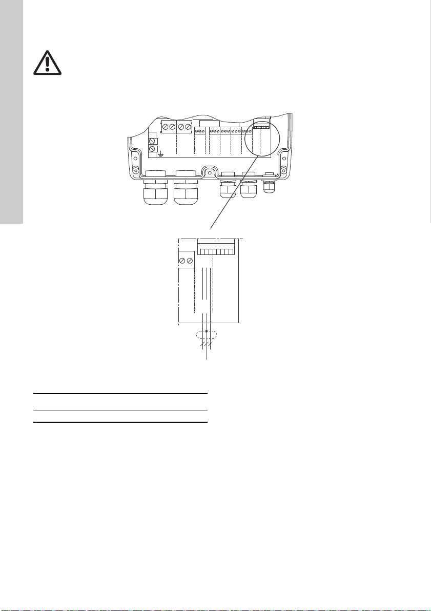
12.1 Description
Using the RS-485 input enables:
• communication via Grundfos fieldbus GENIbus
• connection to the Grundfos Remote Management
(CIU 270) gateway for communication over long
distances.
12.2 CU 300 connected to a PC directly
Figure 31 shows an example of an installation which
is connected to a PC directly via the PC Tool link and
GENIbus.
The installation shown in the example enables
configuration, fault finding and servicing of the
installation by means of a PC with a PC Tool CU 300
software. See fig. 31.
Fig. 31
CU 300 connected to GENIbus network:
Figure 32 shows an example of an installation
connected to a GENIbus network with two CU 300
installations via the RS-485 input. The GENIbus
network is connected to Grundfos Remote
Management (CIU 270) through a PC with internet
access.
The installation shown in the example enables
configuration, fault finding, servicing, data logging of
the connected installations over long distances. See
fig. 32.
You can connect and communicate with up to 32
GENIbus units on one network.
The units can be:
• CU 300 units only
• CU 300 units in combination with other Grundfos
products with GENIbus connection.
Contact Grundfos for further details.
TM06 3619 0715
English (GB)
Pos. Description
1CU 300
E.g. a pH sensor for monitoring of water
2
quality
Fig. 32
TM06 3618 0715
3 Level sensor
4PC
5 PC Tool Link
Pos. Description
1CU 300
2 CIU 270
3PC
31
Page 32
12.3 Electrical installation
POWER
PE
PUMP
RELAY
ALARM
COMNCNO
NONCCOM
AUX
RELAY IN
DIG
IN
+24VDC
GND
GND
+24VDC
IN
SENSOR
12
SENSOR
IN
+24VDC
GND
RS
485
RS
232
B
GND
ARIDTR
RXD
GND
56712109834111213 161514 171819
PE
TXD
RS-485 BRS-485-A
IN
GND
RS
485
RS
232
B
GND
ARIDTR
RXD
GND
18 19
TXD
Y
RS-485
English (GB)
Warning
Never make any connections in the CU 300 unit unless the power supply has been switched off.
CU 300 must be connected in accordance with the rules and standards in force for the
application in question.
The supply voltage and frequency are marked on the nameplate. Make sure that CU 300 is suitable for the
power supply on which it will be used.
Fig. 33
Pos. Description
RS-485 Connection of RS-485, GENIbus
32
TM06 3600 0615
Page 33

12.3.1 Mains supply
Note
POWER, terminals 1, 2 and PE
Connect terminals 1 and 2 to the phase and neutral
leads of the mains supply. You can connect each
terminal to any of the two leads.
Connect the PE terminal to the green/yellow earth
lead. You must connect each PE terminal to an earth
lead of its own.
Maximum cross-section of the leads to be connected
2
.
is 6 mm
Backup fuse: Maximum 16 A.
You must not connect the leads of the
mains supply to terminals 3 and 4.
12.3.2 Pump supply PUMP, terminals 3, 4 and PE
Connect terminals 3 and 4 to the phase and neutral
leads of the pump. You can connect each terminal to
any of the two leads.
Connect the PE terminal to the green/yellow earth
lead. You must connect each PE terminal to an earth
lead of its own.
Maximum cross-section of the leads to be connected
2
.
is 6 mm
12.3.3 Alarm signal relay ALARM RELAY, terminals 5, 6 and 7
Connect terminals 5, 6 and 7 to the internal alarm
signal relay as follows:
• Terminal 5 NC (normally closed).
• Terminal 6 COM (common).
• Terminal 7 NO (normally open).
The relay operates when the alarm and warning
limits are exceeded.
You can select manual or automatic restarting in the
Grundfos GO display "Automatic restarting".
Manual restarting is carried out by means of the On/
Off button on CU 300.
12.3.4 RS-485 input
The RS-485 input, terminals A, Y (GND) and B, is for
external bus communication.
The communication is effected according to the
Grundfos bus protocol, GENIbus, and is two-way
communication.
CU 300 can communicate with a PC with the PC Tool
CU 300 installed.
You need a PC Tool link adapter to communicate
with a PC. Connect the adaptor to CU 300, terminals
A, Y (GND) and B, for direct communication with a
PC on a GENIbus network.
The PC Tool CU 300 enables configuration,
monitoring and fault finding of the actual installation.
The RS-485 input is a low-voltage circuit. Therefore,
you must separate all connections to terminals A, Y
(GND) and B from network circuits by means of
double or reinforced insulation.
A screened, twisted-pair cable is required. The
maximum cable length is 1200 m.
English (GB)
33
Page 34
13. Alarm functions
No contact
Overvoltage
Undervoltage
Dry running
Speed reduction
Overtemperature
Overload
Sensor alarm
No contact
Overvoltage
Undervoltage
Dry running
Speed reduction
Overtemperature
Overload
Sensor alarm
English (GB)
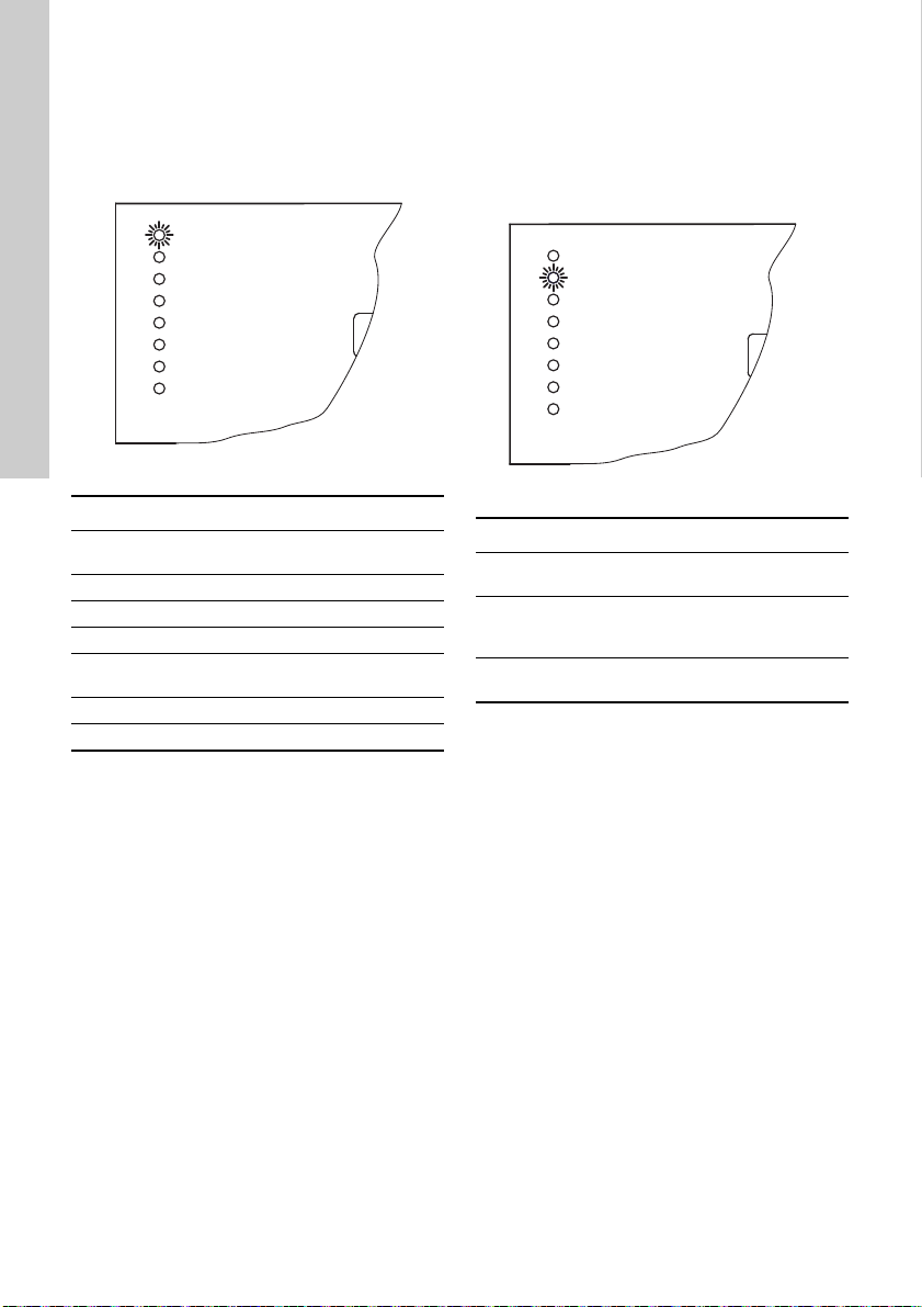
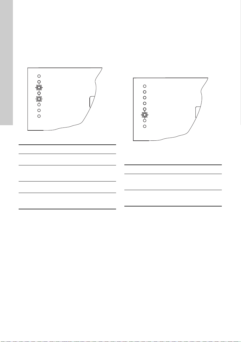
13.1 No contact
The connection and/or communication between CU
300 and the motor is not established.
"No contact"
is permanently on. See fig. 34.
13.2 Overvoltage
The supply voltage to the motor exceeds the
maximum value allowed.
For more information about factory settings, see
section 16. Technical data.
The motor is stopped and "Overvoltage" is
permanently on. See fig. 35.
Fig. 34
Possible cause Remedy
Motor is not an MSE 3
motor.
Motor is not connected. Check connections.
Cable breakage. Check cable.
Poor or no connection. Check connections.
The cable length
exceeds 200 m.
CU 300 is defective. Replace CU 300.
The motor is defective. Replace motor.
Important:
The alarm indication "No contact" will also appear if
the pump and CU 300 do not have the same number
(allocated by the Grundfos GO). The problem may
occur e.g. in connection with replacing a motor or a
CU 300.
Solution:
The pump and CU 300 must be allocated the same
number via the Grundfos GO display "Number".
The alarm "No contact" makes the On/Off button on
CU 300 inactive, and actual operating parameters
cannot be called up. However, installation
parameters can be called up.
"No contact" does not cause a pump stop.
Install an MSE 3 motor.
Reduce cable length.
TM01 2782 0415
Fig. 35
Possible cause Remedy
Unstable power supply.
Too high supply voltage.
Supply voltage outside
voltage range of motor.
Restarting
When the supply voltage lies within the voltage
range of the motor, the motor will restart
automatically.
Contact the power
supply authorities.
Contact the power
supply authorities.
Check installation.
Check installation.
TM01 2783 0415
34
Page 35
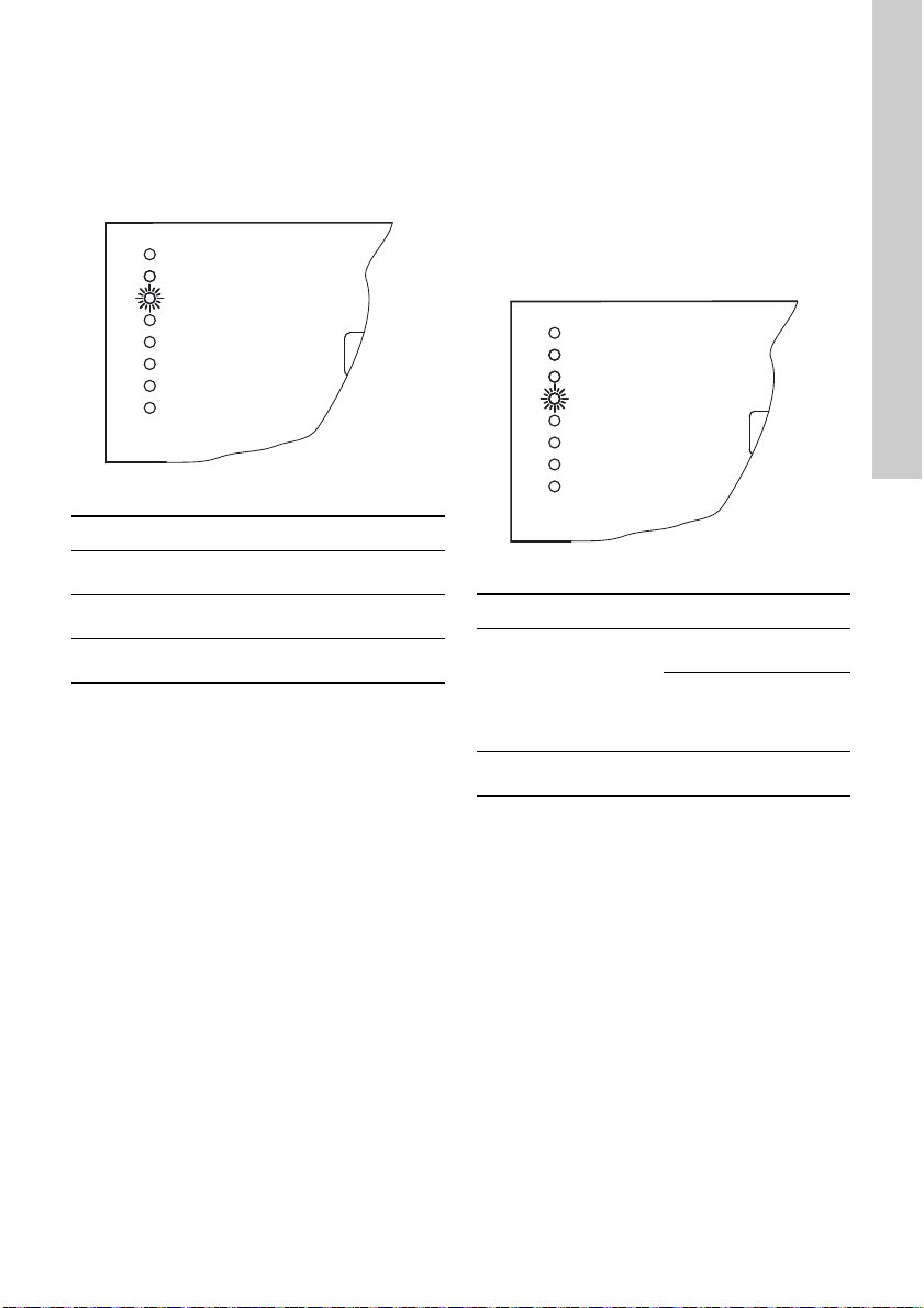
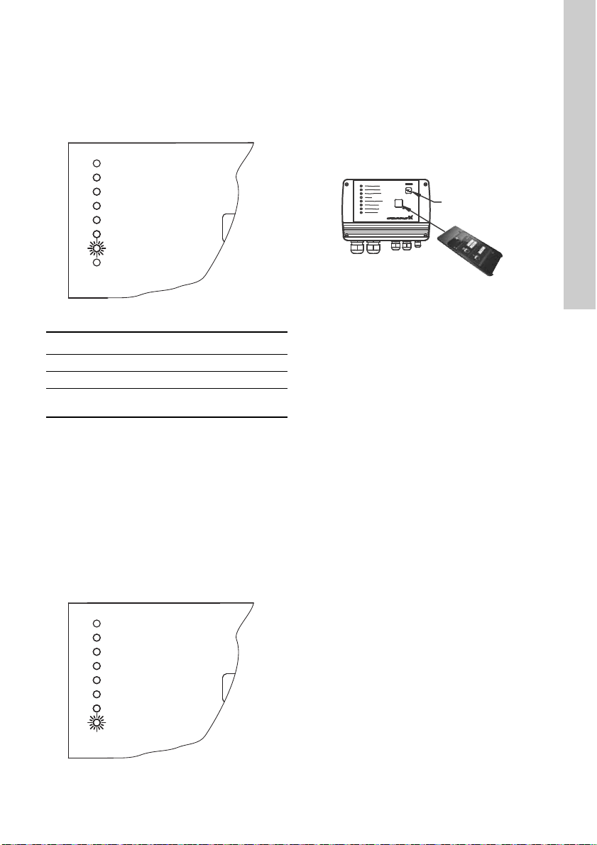
13.3 Undervoltage
No contact
Overvoltage
Undervoltage
Dry running
Speed reduction
Overtemperature
Overload
Sensor alarm
No contact
Overvoltage
Undervoltage
Dry running
Speed reduction
Overtemperature
Overload
Sensor alarm
The supply voltage to the motor is lower than the
minimum value allowed.
For more information about the factory setting, see
section 16. Technical data.
The motor is stopped and "Undervoltage" is
permanently on. See fig. 36.
Fig. 36
13.4 Dry running
The purpose of the dry-running protection is to
protect the pump in case of insufficient water flow.
The dry-running protection makes the conventional
dry-running protection unnecessary.
No additional cables to the motor are required.
The dry-running alarm is activated when the load has
been below the dry-running power limit for an
accumulated time of 5 seconds.
The motor is stopped and "Dry running" is
permanently on. See fig. 37.
TM01 2784 0415
English (GB)
Possible cause Remedy
Unstable power supply.
Supply voltage outside
voltage range of motor.
Voltage drop in mains is
too big.
Restarting
When the supply voltage lies within the voltage
range of the motor, the motor will restart
automatically.
Contact the power
supply authorities.
Check installation.
Increase wire crosssection.
Fig. 37
Possible cause Remedy
Replace pump with a
The pump performance
is too high compared to
the borehole yield.
Borehole filter is
blocked.
Restarting
After 5 minutes (factory setting), or the period set by
means of the Grundfos GO display "Automatic
restarting", the motor will restart automatically.
smaller one.
Reduce pump
performance using the
Grundfos GO display
"Maximum speed".
Borehole service is
required.
35
TM01 2785 0415
Page 36
13.5 Speed reduction
No contact
Overvoltage
Undervoltage
Dry running
Speed reduction
Overtemperature
Overload
Sensor alarm
No contact
Overvoltage
Undervoltage
Dry running
Speed reduction
Overtemperature
Overload
Sensor alarm
English (GB)
At a moderate undervoltage or overload of the motor,
the speed is reduced, but the motor is not stopped.
The speed reduction indicator light is on, and at the
same time the undervoltage or overload light is on.
"Speed reduction" and "Undervoltage" or "Overload"
are permanently on.
In fig. 38, the "Speed reduction" alarm was caused
by undervoltage.
Fig. 38
Possible cause Remedy
Pump is worn, causing
overload.
Wrong combination of
pump and motor,
causing overload.
Unstable power supply,
causing undervoltage.
Too big voltage drop
over the cable, causing
undervoltage.
Speed resuming
When the supply voltage lies within the voltage
range of the motor again and the cause of the
overload has disappeared, the motor resumes
normal speed.
Pump must be serviced.
Replace pump or motor.
Contact the power
supply authorities.
Size cable to avoid too
big voltage drop.
13.6 Overtemperature
The motor temperature is monitored continuously
during operation.
The motor is factory-set to a maximum value. See
section 16. Technical data.
The motor temperature has exceeded the maximum
temperature limit. If the temperature is too high,
there is a risk that the motor electronics will be
damaged.
The motor is stopped and "Overtemperature" is
permanently on. See fig. 39.
TM01 2786 0415
Fig. 39
A too high operating temperature may indicate that
the installation needs service.
Possible cause Remedy
Insufficient cooling or
flow velocity along
motor.
Insufficient cooling due
to incrustation of the
motor.
Restarting
When the motor electronics has cooled sufficiently,
the motor will restart automatically. See section
16. Technical data.
Take out pump and
install flow sleeve.
Clean motor. Install flow
sleeve.
TM01 2787 0415
36
Page 37
13.7 Overload
No contact
Overvoltage
Undervoltage
Dry running
Speed reduction
Overtemperature
Overload
Sensor alarm
No contact
Overvoltage
Undervoltage
Dry running
Speed reduction
Overtemperature
Overload
Sensor alarm
A
The motor is overloaded, i.e. the current
consumption of the motor exceeds the limit value.
For more information about the factory setting, see
section 16. Technical data.
The motor is stopped and "Overload" is permanently
on. See fig. 40.
Fig. 40
Possible cause Remedy
Pump is defective. Pump must be serviced.
Sand or gravel in pump. Pump must be serviced.
Wrong combination of
pump and motor.
Restarting:
After 5 minutes (factory setting), or the period set by
means of the Grundfos GO display "Automatic
restarting", the motor will restart automatically.
Replace pump or motor.
13.8 Sensor alarm
The sensor alarm is activated in two incidents:
• If a connected sensor has detected that an alarm
limit has been exceeded.
• If the sensor signal has fallen outside the
measuring range set.
The motor is stopped and the "Sensor alarm" is
permanently on. See fig. 41.
Restarting
After 5 minutes (factory setting), or the period set by
means of the Grundfos GO display "Automatic
restarting", the motor will restart automatically.
14. CU 300 with Grundfos GO
The remote control Grundfos GO is used for wireless
infra-red communication with CU 300. During
communication, there must be visual contact
between CU 300 and the Grundfos GO. See fig. 42.
Fig. 42 CU 300 communicating with Grundfos
TM01 2788 0415
The Grundfos GO offers possibilities of setting and
status displays for CU 300.
When the communication between the Grundfos GO
and CU 300 has been established, the red indicator
light (A) in the On/Off button will flash.
For general use of the Grundfos GO, see the
operating instructions for this unit.
The menu structure for the Grundfos GO and CU 300
is divided into three main menus, each containing a
number of displays.
• Status
• Settings
• Alarms and warnings
See 14.1 Menu overview on page 38.
GO
English (GB)
TM06 3502 0415
Fig. 41
TM01 2789 0415
37
Page 38

14.1 Menu overview
English (GB)
Status Section Page
External setpoint 15.1.1 External setpoint 40
Controlled from 15.1.2 Controlled from 40
Value, sensor 1
Value, sensor 2
Motor temperature 15.1.4 Motor temperature 40
Motor speed 15.1.5 Motor speed 40
Digital input 15.1.6 Digital input 40
Specific energy 15.1.7 Specific energy 40
Accumulated flow 15.1.8 Accumulated flow 40
Power consumption 15.1.9 Power consumption 40
Energy consumption 15.1.10 Energy consumption 40
Operating hours 15.1.11 Operating hours 40
Number of starts 15.1.12 Number of starts 40
Settings Section Page
Operating mode 15.2.1 Operating mode 40
Control mode 15.2.2 Control mode 40
Setpoint 15.2.3 Setpoint 41
Analog input 1
Analog input 2
Limits, sensor 1 15.2.5 Limits, sensor 1 and 2 41
Min. stop value, sensor 1 15.2.6 Min. stop value, sensor 1 and 2 41
Max. stop value, sensor 1 15.2.7 Max. stop value, sensor 1 and 2 41
Limits, sensor 2 15.2.5 Limits, sensor 1 and 2 41
Min. stop value, sensor 2 15.2.6 Min. stop value, sensor 1 and 2 41
Max. stop value, sensor 2 15.2.7 Max. stop value, sensor 1 and 2 41
External setpoint 15.2.8 External setpoint 41
Warning temperature 15.2.9 Warning, temperature 42
Digital input 1 15.2.10 Digital input 42
Flow per pulse 15.2.11 Flow per pulse 42
Stop limit, accum. flow 15.2.12 Stop limit, accumulated flow 42
Sensor, accum. flow stop 15.2.13 Sensor, accumulated flow stop 42
Stop type, sensor 1
Stop type, sensor 2
Automatic restarting 15.2.15 Automatic restarting 42
Double restarting time 15.2.16 Double restarting time 42
Start delay 15.2.17 Start delay 43
Dewatering 15.2.18 Dewatering 43
Dewatering max. on time
Dewatering max. off time
15.1.3 Value, sensor 1 and 2 40
15.2.4 Analog inputs 41
15.2.14 Stop type, sensor 1 and 2 42
15.2.19 Dewatering, maximum "On" and
"Off" time
Continues on page 39.
43
38
Page 39

Continued from page 38.
Settings Section Page
Dry-running protection 15.2.20 Dry-running protection 43
Dry-running stop 15.2.21 Dry-running stop 43
Maximum speed 15.2.22 Maximum speed 43
Buttons on product 15.2.23 Buttons on product 44
Number 15.2.24 Number 44
Store settings 15.2.25 Store settings 44
Recall settings 15.2.26 Recall settings 44
Undo 15.2.27 Undo 44
Unit configuration 15.2.28 Unit configuration 44
Alarms and warnings Section Page
Alarm log
Warning log
15.3.1 Alarm and warning logs 45
English (GB)
39
Page 40

15. Description of functions
English (GB)
15.1 Status
The "Status" menu for CU 300 offers the possibility
of reading operating parameters.
15.1.1 External setpoint
You can read the value of the external setpoint in this
display.
15.1.2 Controlled from
This display shows the control source:
• CU 300
• external.
15.1.3 Value, sensor 1 and 2
You can read the values measured by sensor 1 and
2 in these displays.
15.1.4 Motor temperature
The actual temperature of the motor electronics
stated in "° C" or "° F".
Tolerance: ± 5 %.
Relation to other disp lays :
To select "° F", choose this in display 15.2.28 Unit
configuration.
15.1.5 Motor speed
The actual speed stated in min
Tolerance: ± 1 %.
15.1.6 Digital input
You can read the value measured by the digital input
in this display. For instance, the actual flow is shown
if the digital input has been connected to a pulse
flowmeter and is setup to monitor the flow.
15.1.7 Specific energy
You can read the specific energy in this display.
15.1.8 Accumulated flow
You can read the pumped water quantity in this
display.
15.1.9 Power consumption
You can read the actual power consumption in this
display.
15.1.10 Energy consumption
You can read the total energy consumption in this
display.
15.1.11 Operating hours
The value of operating hours is accumulated from
the pump's birth and it cannot be reset.
The value is stored in the motor electronics, and it is
kept even if CU 300 is replaced.
The value is updated in the software every 2 minutes
of continuous operation. The displayed value is
updated every two hours.
-1
(rpm).
15.1.12 Number of starts
The value of number of starts is accumulated from
the pump's birth and it cannot be reset.
The value is stored in the motor electronics, and it is
kept even if CU 300 is replaced.
15.2 Settings
The "Settings" menu for CU 300 offers the possibility
of setting operating parameters.
15.2.1 Operating mode
Select one of the following operating modes:
• Max.
Pump operation is set to maximum speed,
irrespective of setpoint. The maximum speed is
set in display 15.2.22 Maximum speed (default:
10,700 min
• Normal.
Normal operating mode, i.e. pump operation is
based on the setpoint set in display
15.2.3 Setpoint.
Examples: Speed set in display 15.2.3 Setpoint
or sensor control.
• Min.
Pump operation is set to minimum speed, 3000
min
• Stop.
The pump is stopped.
Factory setting
"Stop".
15.2.2 Control mode
The following settings are available:
• Open loop.
The speed is set to normal operation based on
the setpoint set in display 15.2.3 Setpoint (e.g.
10,700 min
connected to analog input 2.
See section 9. CU 300 connected to
potentiometer.
• Closed loop.
Controlling according to sensor 1 (type and unit).
Example: Constant-pressure control.
See section 6. CU 300 with constant-pressure
control - 0 to 10 bar.
Relation to other disp lays :
The unit (min
changed according to the unit of the sensor installed.
Factory setting
"Open loop"
-1
).
-1
, irrespective of setpoint.
-1
) or controlled by means of a signal
-1
) of display 15.2.3 Setpoint is
40
Page 41

15.2.3 Setpoint
Setting range: 3000-10,700 min
intervals).
-1
(100 min-1
Dry-running protection
If you use "Setpoint" to reduce the speed, the dryrunning protection will apply only in the "maximum
speed" range, i.e. maximum speed less than 1000
-1
min
. See section 4.3.1 Function.
Relation to other disp lays
The setting in display 15.2.3 Setpoint is overridden
by the "Max." and "Min." settings in display
15.2.1 Operating mode.
If you select "Closed loop" in display 15.2.2 Control
mode, the setpoint is set within the setting range of
the installed sensor.
Example: If the analog input 1 is connected to a
pressure sensor using the unit metre (m) and the
measuring range (0-60), you can set the setpoint
between 0 and 55 m in display 15.2.3 Setpoint.
Factory setting
"10,700 min
-1
"
15.2.4 Analog inputs
Make the following settings according to sensor type:
• Sensor output signal: "-" (not active), 0-20 mA,
4-20 mA, 0-10 V, 2-10 V.
• Setting range unit: m
3
/h, m, %, GPM, ft.
Setting range:
• Minimum value: 0-249 (0, 1, 2, ....249).
• Maximum value: 1-250 (1, 2, ....250).
Factory setting
Sensor output signal: "Not active"
Setting range unit: "m".
15.2.5 Limits, sensor 1 and 2
In these displays, you can set the warning and alarm
limits for sensor 1 and 2.
15.2.6 Min. stop value, sensor 1 and 2
In these displays, you can set the minimum value at
which the pump must stop for sensor 1 and 2.
15.2.7 Max. stop value, sensor 1 and 2
In these displays, you can set the maximum value at
which the pump must stop for sensor 1 and 2.
15.2.8 External setpoint
Set the pump performance control by means of an
external signal.
To be used in the following two situations:
• For installations including a potentiometer.
• In large SCADA systems.
In SCADA systems, this function makes it
possible to control pump performance via remote
controlling (e.g. via a PC).
The following settings are available:
• SPP 1.
Grundfos potentiometer.
See section 2.1 Expansion possibilities.
• 4-20 mA.
• 0-20 mA.
• 2-10 V.
• 0-10 V.
• "Not active"
No external setpoint setting made.
Description
By connecting a current or voltage signal to analog
input 2, you can control the motor speed between
the setpoint set in display 15.2.3 Setpoint and the
lowest speed of 3000 min
If the setpoint is set to 10,700 min
display15.2.3 Setpoint, the motor speed can be
changed between 3000 and 10,700 min
-1
.
-1
in
-1
.
The actual setpoint is calculated by CU 300 and
shown in display 15.2.3 Setpoint.
If an SPP 1 potentiometer is connected, the internal
voltage supply of CU 300 is used to generate the
signal.
See section 9. CU 300 connected to potentiometer.
Relation to other disp lays
If you have set display 15.2.2 Control mode to
"Closed loop" instead of "Open loop" (factory
setting), the controlling is based on signals from
analog input 1. Therefore, the unit in display
15.2.3 Setpoint is changed from min
sensor 1 (m
3
/h, m, %, GPM, ft).
-1
to the unit of
Factory setting
"Not active".
English (GB)
41
Page 42

15.2.9 Warning, temperature
Note
English (GB)
Set the temperature warning limit of the motor.
Setting range: "-" (not active), 2, 4, 6, ....85 °C.
The maximum temperature depends on
the motor type.
Set the temperature warning limit between normal
operating temperature and maximum temperature.
Relation to other disp lays
You find the actual operating temperature in display
15.1.4 Motor temperature.
If the temperature warning limit is exceeded, the
alarm signal relay operates.
Advantage
Instead of a sudden stop without a warning, you get
the following:
• Information that the motor temperature is rising.
• The possibility of planning service of the
installation.
Usage
You can use this function e.g. if the pumped liquid
contains a relatively high level of ochre.
Factory setting
"Not active".
15.2.10 Digital input
Select one of the following functions:
• The digital sensor connected to the digital input
(flow measuring).
• The external on/off switch for the pump.
The following functions are available:
• Not active.
• Stop.
The pump is stopped when a switch connected to
terminals 12 and 13 is closed. No l/pulse to be
set.
See section 15.2.10 Digital input.
• Start.
The pump is started when a switch connected to
terminals 12 and 13 is closed. No l/pulse to be
set.
See section 15.2.10 Digital input.
• Flow.
If you have selected "Flow", the l/pulse value
must also be set.
Setting range: "-" (not active), 0.1, 0.2, 0.3,....20,
21, 22, ....100 l/pulse.
Relation to other disp lays :
The selection of "Flow" in this display makes display
15.2.10 Digital input available, i.e. status of digital
input.
Factory setting
"Not active".
15.2.11 Flow per pulse
In this display the pumped volume per pulse is set.
Setting range: 0.0, 0.1, 0.2, 0.3, ....20, 21, 22, ....100
l/pulse.
For more information, see section 15.2.10 Digital
input.
Factory setting
"0.0 l/pulse"
15.2.12 Stop limit, accumulated flow
In this display, you can set a limit at a specific
amount of pumped water where the pump must stop.
Factory setting
"Disabled".
15.2.13 Sensor, accumulated flow stop
In this display, you can select the sensor for
monitoring the accumulated flow.
Factory setting
"Disabled".
15.2.14 Stop type, sensor 1 and 2
In these displays, you can set the stop type for
sensor 1 and 2. For further information, see
8.2.3 Start and stop limits.
Factory setting
"Disabled".
15.2.15 Automatic restarting
Set the automatic restart time from stop to restart
attempt.
The following settings are available:
• "Enabled"
• "Disabled"
• 0 to 254 minutes.
Factory setting
"5 minutes".
15.2.16 Double restarting time
The following settings are available:
• enabled
• disabled.
When you have selected "Enabled", the restart time
set will be doubled automatically for every 10 motor
stops caused by an alarm. The time is doubled up to
a stop time of 4 hours. After 10 hours of operation
without an alarm, the restart time is automatically set
to:
• The time set in the "Time" field.
•5 minutes (factory setting) if no setting was made
in the "Time" field.
Relation to other disp lays :
If you have selected "Double", the dewatering
function is disabled.
42
Page 43

15.2.17 Start delay
Set a start delay.
This function is used in installations where several
pumps are connected to the same pipeline and
where it is required that the pumps do not start up at
the same time.
The SQE pumps have a built-in soft starter, which
takes the starting current into account.
Setting range: 0-60 s.
Factory setting
"0 s"
15.2.18 Dewatering
For more information about the dewatering function,
see 4.5 Description of the dewatering function.
The following settings are available:
• enabled
• disabled.
Relation to other disp lays
You can set the pump on and off times in the
displays 15.2.19 Dewatering, maximum "On" and
"Off" time.
Factory setting
"Disabled".
15.2.19 Dewatering, maximum "On" and "Off"
time
In these displays, you set the maximum "On" and
"Off" time for the pump for the dewatering function.
For more information, see section 4.5 Description of
the dewatering function.
Operating indication
The dry-running alarm indication on CU 300 is
automatically disabled, when this display setting is
made.
When you select the setting "Disabled", the
dewatering function is disabled, and the dry-running
alarm indication can be activated again.
Relation to other disp lays :
If you select "Double" in display 15.2.15 Automatic
restarting, the dewatering function is disabled.
Factory setting
"Disabled"
15.2.20 Dry-running protection
The following settings are available:
• enabled
• disabled.
The setting in this display applies to both the
dewatering function and the dry-running protection.
In certain installations, it may be necessary to
disable the dry-running protection.
For further information, see section 4.3 Description
of dry-running protection.
Factory setting
"Enabled".
15.2.21 Dry-running stop
The dry-running stop value (dry-running power limit)
is factory-set.
The value depends on the actual motor.
The factory setting depends on the power rating of
the motor. See section 16. Technical data.
When the dry-running protection or the dewatering
function is to be enabled, the minimum value of the
pump power input must be set in this display.
For further information, see section 4.5 Description
of the dewatering function.
Setting range: 0-2500 W.
Relation to other disp lays
15.2.20 Dry-running protection must be set to
"Enabled".
If you have enabled "Double" in display
15.2.16 Double restarting time, the dewatering
function is disabled.
You can read the actual pump power input in display
15.1.9 Power consumption.
Factory setting
Motor size Dry-running stop
0.7 kW 300 W
0.7 kW (SQ/SQE 2-55) 550 W
1.15 kW 680 W
1.55 kW 800 W
1.85 kW 900 W
15.2.22 Maximum speed
Set the maximum speed.
Setting range: 3000 - 10,700 min
Factory setting
10,700 min
-1
.
-1
.
English (GB)
43
Page 44

15.2.23 Buttons on product
Note
English (GB)
In this display, you can disable the On/Off button on
the control unit for protective reasons.
You can set the On/Off button to:
•"Active"
• "Not active".
Factory setting
"Active".
15.2.24 Number
Allocate a number to CU 300 and the pump
connected. CU 300 and the pump must have the
same number.
When allocating a number, the power
supply to other CU 300 units, if any,
must be switched off.
Setting range: "Not active", 1, 2, ....199.
Once a number setting has been made, the factory
setting (not active) is no longer available.
In connection with bus communication, you must
allocate a number to CU 300 and the pump.
If CU 300 and the pump do not have the same
number, the alarm "No contact" will be indicated.
Factory setting
"Not active".
15.2.25 Store settings
You can store the actual settings for later use in this
display.
15.2.26 Recall settings
You can recall the last stored settings that the pump
will then use in this display.
15.2.27 Undo
You can undo previously made settings in this
display.
15.2.28 Unit configuration
You can select between SI and US units in this
display. The setting can be made generally for all
parameters or customised for each individual
parameter.
44
Page 45

15.3 Alarms and warnings
15.3.1 Alarm and warning logs
These displays show the types of warnings and
alarms that may have appeared.
Possible warnings and alarms are described in the
following table:
Indication Description
No fault indication No alarms are registered by CU 300.
No contact to pump No communication between CU 300 and the pump.
Overvoltage The supply voltage exceeds the limit value.
Undervoltage The supply voltage is below the limit value.
Dry running The dry-running protection of the pump has been activated.
Overtemperature The motor temperature exceeds the limit value.
Overload The current consumption of the motor exceeds the limit value.
Alarm, sensor 1
Alarm, sensor 2
Sensor 1 defective
Sensor 2 defective
Warning, sensor 1 The sensor 1 warning limit has been exceeded.
Warning, sensor 2 The sensor 2 warning limit has been exceeded.
Warning, temperature The temperature warning limit has been exceeded.
Relation to other disp lays :
The setting in display 15.2.3 Setpoint is overridden
by the "Max." and "Min." settings in display
15.2.1 Operating mode.
If you select "Closed loop" in display 15.2.2 Control
mode, the setpoint is set within the setting range of
the installed sensor.
Example: If the analog input 1 is connected to a
pressure sensor using the unit metre (m) and the
measuring range (0-60), you can set the setpoint
between 0 and 55 m in display 15.2.3 Setpoint.
The sensor 1 signal has fallen outside the measuring range set.
Note: The sensor number refers to the terminal connection input number.
The sensor 2 signal has fallen outside the measuring range set.
Note: The sensor number refers to the terminal connection input number.
The sensor signal of a 4-20 mA or 2-10 V sensor is below 2 mA or 1 V
respectively.
The sensor signal of a 4-20 mA or 2-10 V sensor is below 2 mA or 1 V
respectively.
English (GB)
45
Page 46

16. Technical data
232
114
195
English (GB)
Supply voltage
1 x 100-240 V - 10 %/+ 6 %, 50/60 Hz, PE.
Power consumption
5 W.
Backup fuse
Maximum 16 A.
Current consumption
Maximum 130 mA.
Mains borne signalling
Frequency shift keying (FSK).
(132.45 kHz, ± 0.6 kHz).
Enclosure class
IP55.
Maximum difference between CU 300 and pump
200 metres.
Ambient temperature
• During operation: -30 to 50 °C
(must not be exposed to direct sunlight).
• During storage: -30 to 60 °C.
Weight
2.0 kg.
Relative air humidity
Maximum 95 %.
Materials
The CU 300 box is made of black PPO.
EMC (Electromagnetic compatibility)
See Declaration of conformity on page 48.
Dimensional sketch
Inputs/output
Potential-free changeover contact.
Maximum contact load: 250 VAC.
Maximum current: 1 A.
Minimum contact load: 5 VDC, 10 mA.
Alarm relay
Specifications: 250 VAC, 8 A, AC1.
Potential-free changeover contact.
Maximum contact load: Safety extra-low
voltage to be used only.
Maximum current: 1 A.
Minimum contact load: 5 VDC, 10 mA.
Specifications: 250 VAC, 8 A, AC1.
Auxiliary relay
External potential-free contact.
Logic "0": U
Logic "1": U
Digital input
Voltage signal: 0-10 VDC/2-10 VDC, Ri = 11
kΩ.
Tolerance: at maximum voltage signal.
Screened cable is recommended.
Maximum cable length: 500 m.
Current signal: DC 0-20 mA/4-20 mA, R
Sensor 1
Ω.
Tolerance: ± 3 % at maximum current signal.
Screened cable is recommended.
> 3.2 V.
in
< 0.9 V.
in
Maximum cable length: 500 m.
Potentiometer SPP 1: 0-24 VDC, 10 k (via
internal voltage supply).
Screened cable is recommended.
Maximum cable length: 100 m.
Voltage signal: 0-10 VDC/2-10 VDC, R
kΩ.
Tolerance: ± 3 % at maximum voltage signal.
Screened cable is recommended.
Sensor 2
Maximum cable length: 500 m.
Current signal: DC 0-20 mA/4-20 mA, Ri = 500
Ω.
Tolerance: ± 3 % at maximum current signal.
Screened cable is recommended.
Maximum cable length: 500 m.
Grundfos fieldbus, GENIbus.
0.25 - 1 mm
Maximum cable length: 1200 m.
RS-485
2
screened 2-core cable.
= 500
i
= 11
i
46
Fig. 43
TM01 2781 4601
Page 47

Factory settings
Alarm
0.7 kW 1.15 kW 1.55 kW 1.85 kW 0.7 kW
Overvoltage
Undervoltage
Dry-running
stop
Dry-running
protection
Speed
reduction
Electronics
temperature
Overload 5.2 A 8.4 A 11 A 12.3 A 12.1 A
Sensor alarm "No sensor used" (Grundfos GO setting). See section 15.2.4 Analog inputs)
1) 200-240 V motors: Operation is guaranteed up to 280 VAC.
100-115 V motors: Operation is guaranteed up to 150 VAC.
In order to avoid unnecessary stops, the overvoltage stop limit is as stated.
2) Applies only to SQ/SQE 2-55.
Accuracy of Grundfos GO readings
Display Accuracy
External setpoint ± 5 %
Motor temperature ± 5 %
Motor speed ± 1 %
Power input ± 5 %
Power consumption ± 5 %
Energy consumption ± 5 %
Sensors
The sensor signal accuracy depends on the sensor
type. See the sensor specifications in question.
1)
320 VAC 320 VAC 320 VAC 320 VAC 185 VAC
Speed reduction:
190 V
Stop limit: 150 V Stop limit: 150 V Stop limit: 150 V Stop limit: 150 V Stop limit: 75 V
300 W
2)
550 W
"Active" (Grundfos GO setting). See section 15.2.20 Dry-running protection)
In connection with undervoltage or overload
Stop limit: 65 °C Stop limit: 75 °C Stop limit: 85 °C Stop limit: 85 °C Stop limit: 85 °C
Restart: 55 °C Restart: 65 °C Restart: 75 °C Restart: 75 °C Restart: 75 °C
200-240 V motors
Speed reduction:
190 V
680 W 800 W 900 W 300 W
Speed reduction:
210 V
Speed reduction:
210 V
100-115 V
motors
Speed reduction:
90 V
English (GB)
17. Disposal
This product or parts of it must be disposed of in an
environmentally sound way:
1. Use the public or private waste collection service.
2. If this is not possible, contact the nearest
Grundfos company or service workshop.
Subject to alterations.
47
Page 48

Declaration of conformity
Declaration of conformity 1
GB: EC/EU declaration of conformity
We, Grundfos, declare under our sole responsibility that the product
CU 300, to which the declaration below relates, is in conformity with
the Council Directives listed below on the approximation of the laws
of the EC/EU member states.
Note: There are two sets of Council Directives and standards listed
below. One set applies until and including 19th April 2016. The other
set applies from 20th April 2016 and onwards.
These Directives and standards apply until and including 19th April
2016:
– Low Voltage Directive (2006/95/EC).
Standards used:
EN 60335-1:2012
– EMC Directive (2004/108/EC).
Standards used:
EN 55014-1:2006 + A1:2009 + A2:2011
EN 55014-2:1997 + A1:2001 + A2:2008
This EC/EU declaration of conformity is only valid when published as
These Directives and standards apply from 20th April 2016 and
onwards:
— Low Voltage Directive (2014/35/EU).
Standards used:
EN 60335-1:2012
— EMC Directive (2014/30/EU).
Standards used:
EN 55014-1:2006 + A1:2009 + A2:2011
EN 55014-2:1997 + A1:2001 + A2:2008
part of the Grundfos installation and operating instructions
(publication number 96427972 0915).
Bjerringbro, 15th June 2015
Svend Aage Kaae
Director
Grundfos Holding A/S
Poul Due Jensens Vej 7
8850 Bjerringbro, Denmark
Person authorised to compile the technical file and
empowered to sign the EC declaration of conformity.
48
Page 49

49
Page 50

Grundfos companies
Argentina
Bombas GRUNDFOS de Argentina S.A.
Ruta Panamericana km. 37.500 Centro
Industrial Garin
1619 Garín Pcia. de B.A.
Phone: +54-3327 414 444
Telefax: +54-3327 45 3190
Australia
GRUNDFOS Pumps Pty. Ltd.
P.O. Box 2040
Regency Park
South Australia 5942
Phone: +61-8-8461-4611
Telefax: +61-8-8340 0155
Austria
GRUNDFOS Pumpen Vertrieb
Ges.m.b.H.
Grundfosstraße 2
A-5082 Grödig/Salzburg
Tel.: +43-6246-883-0
Telefax: +43-6246-883-30
Belgium
N.V. GRUNDFOS Bellux S.A.
Boomsesteenweg 81-83
B-2630 Aartselaar
Tél.: +32-3-870 7300
Télécopie: +32-3-870 7301
Belarus
Представительство ГРУНДФОС в
Минске
220125, Минск
ул. Шафарнянская, 11, оф. 56, БЦ
«Порт»
Тел.: +7 (375 17) 286 39 72/73
Факс: +7 (375 17) 286 39 71
E-mail: minsk@grundfos.com
Bosna and Herzegovina
GRUNDFOS Sarajevo
Zmaja od Bosne 7-7A,
BH-71000 Sarajevo
Phone: +387 33 592 480
Telefax: +387 33 590 465
www.ba.grundfos.com
e-mail: grundfos@bih.net.ba
Brazil
BOMBAS GRUNDFOS DO BRASIL
Av. Humberto de Alencar Castelo
Branco, 630
CEP 09850 - 300
São Bernardo do Campo - SP
Phone: +55-11 4393 5533
Telefax: +55-11 4343 5015
Bulgaria
Grundfos Bulgaria EOOD
Slatina District
Iztochna Tangenta street no. 100
BG - 1592 Sofia
Tel. +359 2 49 22 200
Fax. +359 2 49 22 201
email: bulgaria@grundfos.bg
Canada
GRUNDFOS Canada Inc.
2941 Brighton Road
Oakville, Ontario
L6H 6C9
Phone: +1-905 829 9533
Telefax: +1-905 829 9512
China
GRUNDFOS Pumps (Shanghai) Co. Ltd.
10F The Hub, No. 33 Suhong Road
Minhang District
Shanghai 201106
PRC
Phone: +86 21 612 252 22
Telefax: +86 21 612 253 33
Croatia
GRUNDFOS CROATIA d.o.o.
Buzinski prilaz 38, Buzin
HR-10010 Zagreb
Phone: +385 1 6595 400
Telefax: +385 1 6595 499
www.hr.grundfos.com
Czech Republic
GRUNDFOS s.r.o.
Čajkovského 21
779 00 Olomouc
Phone: +420-585-716 111
Telefax: +420-585-716 299
Denmark
GRUNDFOS DK A/S
Martin Bachs Vej 3
DK-8850 Bjerringbro
Tlf.: +45-87 50 50 50
Telefax: +45-87 50 51 51
E-mail: info_GDK@grundfos.com
www.grundfos.com/DK
Estonia
GRUNDFOS Pumps Eesti OÜ
Peterburi tee 92G
11415 Tallinn
Tel: + 372 606 1690
Fax: + 372 606 1691
Finland
OY GRUNDFOS Pumput AB
Trukkikuja 1
FI-01360 Vantaa
Phone: +358-(0) 207 889 500
Telefax: +358-(0) 207 889 550
France
Pompes GRUNDFOS Distribution S.A.
Parc d’Activités de Chesnes
57, rue de Malacombe
F-38290 St. Quentin Fallavier (Lyon)
Tél.: +33-4 74 82 15 15
Télécopie: +33-4 74 94 10 51
Germany
GRUNDFOS GMBH
Schlüterstr. 33
40699 Erkrath
Tel.: +49-(0) 211 929 69-0
Telefax: +49-(0) 211 929 69-3799
e-mail: infoservice@grundfos.de
Service in Deutschland:
e-mail: kundendienst@grundfos.de
Greece
GRUNDFOS Hellas A.E.B.E.
20th km. Athinon-Markopoulou Av.
P.O. Box 71
GR-19002 Peania
Phone: +0030-210-66 83 400
Telefax: +0030-210-66 46 273
Hong Kong
GRUNDFOS Pumps (Hong Kong) Ltd.
Unit 1, Ground floor
Siu Wai Industrial Centre
29-33 Wing Hong Street &
68 King Lam Street, Cheung Sha Wan
Kowloon
Phone: +852-27861706 / 27861741
Telefax: +852-27858664
Hungary
GRUNDFOS Hungária Kft.
Park u. 8
H-2045 Törökbálint,
Phone: +36-23 511 110
Telefax: +36-23 511 111
India
GRUNDFOS Pumps India Private
Limited
118 Old Mahabalipuram Road
Thoraipakkam
Chennai 600 096
Phone: +91-44 2496 6800
Indonesia
PT. GRUNDFOS POMPA
Graha Intirub Lt. 2 & 3
Jln. Cililitan Besar No.454. Makasar,
Jakarta Timur
ID-Jakarta 13650
Phone: +62 21-469-51900
Telefax: +62 21-460 6910 / 460 6901
Ireland
GRUNDFOS (Ireland) Ltd.
Unit A, Merrywell Business Park
Ballymount Road Lower
Dublin 12
Phone: +353-1-4089 800
Telefax: +353-1-4089 830
Italy
GRUNDFOS Pompe Italia S.r.l.
Via Gran Sasso 4
I-20060 Truccazzano (Milano)
Tel.: +39-02-95838112
Telefax: +39-02-95309290 / 95838461
Japan
GRUNDFOS Pumps K.K.
Gotanda Metalion Bldg., 5F,
5-21-15, Higashi-gotanda
Shiagawa-ku, Tokyo
141-0022 Japan
Phone: +81 35 448 1391
Telefax: +81 35 448 9619
Korea
GRUNDFOS Pumps Korea Ltd.
6th Floor, Aju Building 679-5
Yeoksam-dong, Kangnam-ku, 135-916
Seoul, Korea
Phone: +82-2-5317 600
Telefax: +82-2-5633 725
Latvia
SIA GRUNDFOS Pumps Latvia
Deglava biznesa centrs
Augusta Deglava ielā 60, LV-1035, Rīga,
Tālr.: + 371 714 9640, 7 149 641
Fakss: + 371 914 9646
Lithuania
GRUNDFOS Pumps UAB
Smolensko g. 6
LT-03201 Vilnius
Tel: + 370 52 395 430
Fax: + 370 52 395 431
Page 51

Malaysia
GRUNDFOS Pumps Sdn. Bhd.
7 Jalan Peguam U1/25
Glenmarie Industrial Park
40150 Shah Alam
Selangor
Phone: +60-3-5569 2922
Telefax: +60-3-5569 2866
Mexico
Bombas GRUNDFOS de México S.A. de
C.V.
Boulevard TLC No. 15
Parque Industrial Stiva Aeropuerto
Apodaca, N.L. 66600
Phone: +52-81-8144 4000
Telefax: +52-81-8144 4010
Netherlands
GRUNDFOS Netherlands
Veluwezoom 35
1326 AE Almere
Postbus 22015
1302 CA ALMERE
Tel.: +31-88-478 6336
Telefax: +31-88-478 6332
E-mail: info_gnl@grundfos.com
New Zealand
GRUNDFOS Pumps NZ Ltd.
17 Beatrice Tinsley Crescent
North Harbour Industrial Estate
Albany, Auckland
Phone: +64-9-415 3240
Telefax: +64-9-415 3250
Norway
GRUNDFOS Pumper A/S
Strømsveien 344
Postboks 235, Leirdal
N-1011 Oslo
Tlf.: +47-22 90 47 00
Telefax: +47-22 32 21 50
Poland
GRUNDFOS Pompy Sp. z o.o.
ul. Klonowa 23
Baranowo k. Poznania
PL-62-081 Przeźmierowo
Tel: (+48-61) 650 13 00
Fax: (+48-61) 650 13 50
Portugal
Bombas GRUNDFOS Portugal, S.A.
Rua Calvet de Magalhães, 241
Apartado 1079
P-2770-153 Paço de Arcos
Tel.: +351-21-440 76 00
Telefax: +351-21-440 76 90
Romania
GRUNDFOS Pompe România SRL
Bd. Biruintei, nr 103
Pantelimon county Ilfov
Phone: +40 21 200 4100
Telefax: +40 21 200 4101
E-mail: romania@grundfos.ro
Russia
ООО Грундфос Россия
109544, г. Москва, ул. Школьная, 39-
41, стр. 1
Тел. (+7) 495 564-88-00 (495) 737-3000
Факс (+7) 495 564 88 11
E-mail grundfos.moscow@grundfos.com
Serbia
Grundfos Srbija d.o.o.
Omladinskih brigada 90b
11070 Novi Beograd
Phone: +381 11 2258 740
Telefax: +381 11 2281 769
www.rs.grundfos.com
Singapore
GRUNDFOS (Singapore) Pte. Ltd.
25 Jalan Tukang
Singapore 619264
Phone: +65-6681 9688
Telefax: +65-6681 9689
Slovakia
GRUNDFOS s.r.o.
Prievozská 4D
821 09 BRATISLAVA
Phona: +421 2 5020 1426
sk.grundfos.com
Slovenia
GRUNDFOS d.o.o.
Šlandrova 8b, SI-1231 Ljubljana-Črnuče
Phone: +386 31 718 808
Telefax: +386 (0)1 5680 619
E-mail: slovenia@grundfos.si
South Africa
GRUNDFOS (PTY) LTD
Corner Mountjoy and George Allen
Roads
Wilbart Ext. 2
Bedfordview 2008
Phone: (+27) 11 579 4800
Fax: (+27) 11 455 6066
E-mail: lsmart@grundfos.com
Spain
Bombas GRUNDFOS España S.A.
Camino de la Fuentecilla, s/n
E-28110 Algete (Madrid)
Tel.: +34-91-848 8800
Telefax: +34-91-628 0465
Sweden
GRUNDFOS AB
Box 333 (Lunnagårdsgatan 6)
431 24 Mölndal
Tel.: +46 31 332 23 000
Telefax: +46 31 331 94 60
Switzerland
GRUNDFOS Pumpen AG
Bruggacherstrasse 10
CH-8117 Fällanden/ZH
Tel.: +41-44-806 8111
Telefax: +41-44-806 8115
Taiwan
GRUNDFOS Pumps (Taiwan) Ltd.
7 Floor, 219 Min-Chuan Road
Taichung, Taiwan, R.O.C.
Phone: +886-4-2305 0868
Telefax: +886-4-2305 0878
Thailand
GRUNDFOS (Thailand) Ltd.
92 Chaloem Phrakiat Rama 9 Road,
Dokmai, Pravej, Bangkok 10250
Phone: +66-2-725 8999
Telefax: +66-2-725 8998
Turkey
GRUNDFOS POMPA San. ve Tic. Ltd.
Sti.
Gebze Organize Sanayi Bölgesi
Ihsan dede Caddesi,
2. yol 200. Sokak No. 204
41490 Gebze/ Kocaeli
Phone: +90 - 262-679 7979
Telefax: +90 - 262-679 7905
E-mail: satis@grundfos.com
Ukraine
Бізнес Центр Європа
Столичне шосе, 103
м. Київ, 03131, Україна
Телефон: (+38 044) 237 04 00
Факс.: (+38 044) 237 04 01
E-mail: ukraine@grundfos.com
United Arab Emirates
GRUNDFOS Gulf Distribution
P.O. Box 16768
Jebel Ali Free Zone
Dubai
Phone: +971 4 8815 166
Telefax: +971 4 8815 136
United Kingdom
GRUNDFOS Pumps Ltd.
Grovebury Road
Leighton Buzzard/Beds. LU7 4TL
Phone: +44-1525-850000
Telefax: +44-1525-850011
U.S.A.
GRUNDFOS Pumps Corporation
17100 West 118th Terrace
Olathe, Kansas 66061
Phone: +1-913-227-3400
Telefax: +1-913-227-3500
Uzbekistan
Grundfos Tashkent, Uzbekistan The Representative Office of Grundfos Kazakhstan
in Uzbekistan
38a, Oybek street, Tashkent
Телефон: (+998) 71 150 3290 / 71 150
3291
Факс: (+998) 71 150 3292
Addresses Revised 29.09.2015
Grundfos companies
Page 52

96427972 0915
ECM: 1156881
www.grundfos.com
© Copyright Grundfos Holding A/S
owned by Grundfos Holding A/S or Grundfos A/ S, Denmark. All rights reserved worldwide.
The name Grundfos, the Grundfos logo, and be think innovate are registered trademarks
 Loading...