

Page 1

CR, CRN 95-155
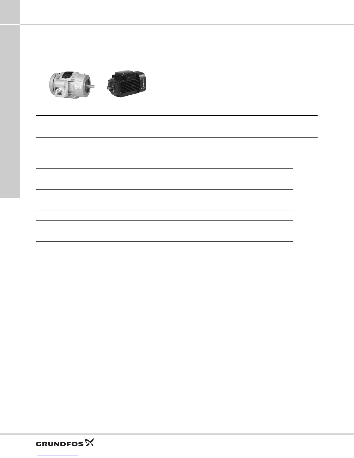
Vertical, multistage centrifugal pumps
60 Hz
(NEMA)
GRUNDFOS DATA BOOKLET
Page 2

CR, CRN 95-155
Table of contents
1. Product introduction 3
Applications 3
Pumped liquids 3
Performance range 4
Applications 5
Product range 6
Pump 7
Motor 7
Terminal box positions 7
Viscosity 7
2. Construction 8
CR 95, 125 and 155 8
CRN 95, 125 and 155 9
Type keys 10
3. Operating and inlet pressures 11
Max. operating pressure and liquid temperature 11
Operating range of the shaft seal 12
Maximum inlet pressure 13
4. Selection and sizing 14
Selection of pumps 14
How to read the curve charts 17
Guidelines to performance curves 17
5. Performance curves and technical data 18
CR 95 18
CRN 95 20
CR 125 22
CRN 125 24
CR 155 26
CRN 155 28
6. Motor data 30
Standard motors, 60 Hz 30
7. List of pumped liquids 31
8. Accessories 33
9. Grundfos Product Center 34
Grundfos GO 35
2
Page 3

CR, CRN 95-155
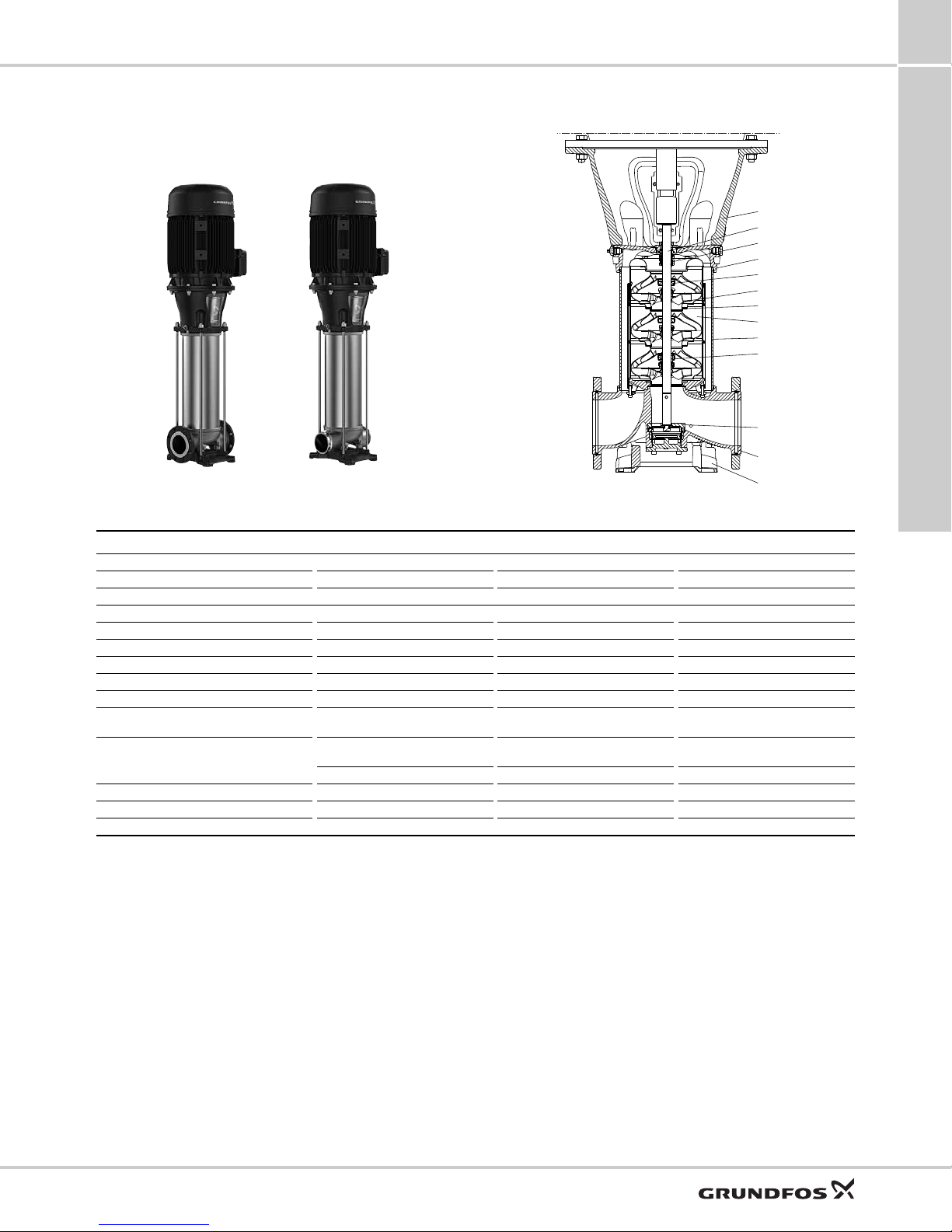
1. Product introduction
1
This data booklet covers Grundfos CR and CRN
pumps with these nominal flow sizes:
• CR, CRN 95
• CR, CRN 125
• CR, CRN 155.
Fig. 1 CR, CRN 95-155
CR, CRN pumps are vertical multistage, centrifugal
pumps. The in-line design of the pumps enables
installation in a horizontal one-pipe system where the
inlet and outlet ports are in the same horizontal level
and have the same pipe dimensions. This design
provides a more compact pump design.
The pumps are available in various sizes and various
numbers of stages to deliver the flow and pressure
required.
CR, CRN pumps are designed for a variety of
applications ranging from the pumping of potable water
to the pumping of chemicals. The pumps are therefore
suitable for a wide diversity of pumping systems where
the performance and material of the pump meet
specific demands.
A CR, CRN pump consists of two main components:
the motor and the pump unit.
The pump unit consists of optimized hydraulics,
various types of connections, a sleeve, a pump head
and various other parts. See Construction, page 8.
CR, CRN pumps are available in various material
versions according to the pumped liquid.
CR pumps with ANSI/NSF 61 and ANSI/NSF 372
listing are available. FKM variants are only available
with ANSI/NSF 372 listing. See UL file MH24600 or
contact Grundfos.
Applications
The new CR, CRN range is suitable for numerous
applications identical to the applications which the
current CR, CRN pumps handle today. The following
applications are some typical examples.
Water supply:
• Filtration and transport water works
• Distribution from water works
• Pressure boosting of mains.
Industrial:
• Pressure boosting
• Process water transfer
• Boiler feed
• Cooling and air conditioning
• Firefighting systems
• District energy systems
• Special liquids transfer.
TM06 9062 1617
Water treatment:
• Filtration
• Brackish water reverse osmosis.
Product introduction
Pumped liquids
Thin, non-explosive liquids, not containing solid
particles or fibers. The liquid must not attack the pump
materials.
CR pumps are suitable for non-corrosive liquids and
are to be used for liquid transfer, circulation and
pressure boosting of cold or hot clean water.
CRN pumps are suitable for industrial liquids and are
to be used in systems where all parts in contact with
the liquid must be made of high-grade stainless steel.
For further details see List of pumped liquids, page 31.
3
Page 4

1
250 300 350 400 500 600 700 800 1000 1200
Q [US GPM]
80
100
150
200
300
400
600
800
1000
[ft]
H
57 60 70 80 90 100100 200
Q [m³/h]
25
30
40
50
60
70
80
100100
200
300
[m]
H
60 Hz
CR(N) 95
CRN 125
CR 125
CRN 155
CR 155
250 300 350 400 500 600 700 800 1000 1200
Q [US GPM]
0
20
40
60
80
[%]
Eff
CR, CRN 95-155
Product introduction
Performance range
Fig. 2 Performance range, CR, CRN
4
TM06 5583 3718
Page 5

CR, CRN 95-155
1
Applications
Application CR CRN
Water supply
Filtration and transfer at waterworks ●
Distribution from waterworks ●
Pressure boosting in mains ●
Pressure boosting in high-rise buildings, hotels, etc. ●
Pressure boosting for industrial water supply ●
Industry
Pressure boosting
Process-water systems ●●
Washing and cleaning systems
Vehicle-washing tunnels ●
Firefighting systems ● -
Liquid transfer
Cooling and air-conditioning systems (refrigerants) ●
Boiler feed and condensate systems ●
Machine tools (cooling lubricants) ●●
Aquafarming ●
Special transfer duties
Oils and alcohols ●●
Acids and alkalis - ●
Glycol and coolants ● -
Water treatment
Ultra-filtration systems - ●
Reverse osmosis systems - ●
Softening, ionizing, demineralizing systems - ●
Distillation systems - ●
Separators ●●
Swimming pools - ●
Irrigation
Field irrigation (flooding) ●
Sprinkler irrigation ●
Drip-feed irrigation ●
● Recommended version.
❍ Alternative version.
* For applications involving CIP (cleaning-in-place) and motors above 75 Hp (55 kW,) a bearing flange must be used and a base without thrust
handling device or blind flange.
*
●●
❍
❍
❍
❍
❍
❍
❍
❍
❍
❍
❍
❍
Product introduction
5
Page 6

1
CR, CRN 95-155
Product introduction
Product range
Range CR, CRN 95 CR, CRN 125 CR, CRN 155
3
Rated flow rate [US gpm (m
Liquid temperature [°F (°C)] -22 to +248
Maximum pump efficiency [%] 82.5 82.5 82.5
CR, CRN pumps
Flow rate [US gpm] 255-660 330-860 410-1060
Maximum pressure [psi (bar)] 537
Motor power [Hp (kW)]
Version
CR:
Cast iron and stainless steel
EN 1.4301/AISI 304
CRN:
Stainless steel
EN 1.4401/AISI 316
CR pipe connection
Flange 4" ANSI 6" ANSI
CRN pipe connection
Flange 4" ANSI 6" ANSI
PJE coupling (Victaulic type) 4" 6"
1)
CRN 95 to 155 with HQQE shaft seal: -40 to +248 °F (-40 to +120 °C).
2)
CR pumps: Maximum operating pressure is 363 psi (25 bar).
/h)]
500 (114)
2)
(37) 566
20-75 (15-55)
●● ●
●● ●
660 (150) 820 (186)
1)
(-30 to +120)
2)
(39) 580
20-150 (15-111) 25-150 (18-111)
2)
(40)
6
Page 7

CR, CRN 95-155
Impellers
Base
Motor
Coupling
Pump head
Sleeve
Staybolts
Base plate
Shaft seal
(cartridge type)
6 o’clock
position
(standard)
9 o’clock
position
12 o’clock
position
3 o’clock
position
1
Pump
The CR pumps are non-self-priming, vertical
multistage centrifugal pumps.
The pumps are available with a Grundfos or Baldor
standard motor.
The pump consists of a base and a pump head. The
chamber stack and the sleeve are secured between
the base and the pump head by means of staybolts.
The base has inlet and outlet ports on the same level
(in line). All pumps are fitted with a maintenance-free
mechanical shaft seal of the cartridge type.
Grundfos E-motors
We also offer frequency-controlled CRE, CRNE pumps
which are the ideal choice for a number of applications
characterized by a demand for variable flow at
constant pressure. These pumps are suited for water
supply systems and pressure boosting as well as for
industrial applications. Depending on the application,
the pumps offer energy savings, increased comfort and
improved processing.
Optional motors
The Grundfos standard range of motors covers a wide
variety of application demands. However, for special
applications or operating conditions, custom-built
motor solutions can be provided.
For special applications or operating conditions, we
offer custom-built motors such as
• Explosion-proof motors
• Motors with anti-condensation heating unit
• motors with thermal protection.
Motor protection
Single-phase Grundfos motors have a built-in thermal
overload switch (TP 211 according to IEC 34-11).
Three-phase motors must be connected to a
motor-protective circuit breaker according to local
regulations.
Three-phase Grundfos ML motors 5 Hp ( 5 kW) and
larger have a built-in thermistor (PTC) according to
DIN 44082 (TP 211 according to IEC 34-11).
Product introduction
Fig. 3 CR pump
Motor
Grundfos ML standard and Baldor motors
CR, CRN pumps are fitted with a totally enclosed,
fan-cooled, 2-pole Grundfos or Baldor standard motor.
Angular contact bearings are fitted to the drive end on
motors up to 75 Hp (56 kW). This ensures that the
motor bearing life (L10) is extended to match that of
the pump.
Electrical data
Efficiency class NEMA Premium
Insulation class F/B
Enclosure type* TEFC
Rated voltage**
Number of poles 2
Frequency, standard motors 60 Hz
* A different enclosure type is available on request.
** Different voltages are available on request.
3 x 208-230 VΔ / 3 x 380-480 V Y
3 x 575 VΔ (only Canada)
GR5357 - GR3395
Terminal box positions
As standard, the terminal box is fitted on the inlet side
of the pump.
TM03 3658 0606
Fig. 4 Terminal box positions
Viscosity
The pumping of liquids with densities or kinematic
viscosities higher than those of water will cause a
considerable pressure drop, a drop in the hydraulic
performance and a rise in the power consumption.
In such situations, the pump must be fitted with a
larger motor. If in doubt, contact Grundfos.
7
Page 8

2
ANSI flange
1
2
3
4
6
8
9
10
12
11
13
5
7
Construction
2. Construction
CR 95, 125 and 155
CR, CRN 95-155
TM06 9206 1917
Materials, CR
Pos. Designation Materials DIN/EN ≈ AISI/ASTM
1 Motor stool Ductile cast iron EN-GJS-500-7 ASTM A536-84 70-50-05
2 Shaft Stainless steel
EN10088 1.4057
EN10088 1.4462
3 Shaft seal (seal faces) Silicon carbide/Silicon carbide - -
4 Pump head Ductile cast iron EN-GJS-500-7 ASTM A536-84 70-50-05
5 Support bearing (bush) Carbon-graphite filled PTFE
6 Impeller Stainless steel EN10088 1.4301 AISI 304
7 Neck ring PEEK - -
8 Chamber Stainless steel EN10088 1.4301 AISI 304
9 Sleeve Stainless steel
10 Bearing ring
11 Thrust handling device
3)
Tungsten carbide/Tungsten
carbide
Stainless steel
EN10088 1.4301
EN10088 1.4404
--
EN10088 1.4401
EN10283 1.4408
Silicon carbide/Tungsten carbide - -
12 Base Ductile cast iron EN-GJS-500-7 ASTM A536-84 70-50-05
13 Base plate Ductile cast iron EN-GJS-500-7 ASTM A536-84 70-50-05
Rubber parts EPDM or FKM - -
1)
Applies to CR 95.
2)
Applies to CR 125 to CR 155.
3)
Only fitted on pumps with 100 Hp (75 kW) motors or larger.
1)
2)
1)
2)
EN10088 1.4057=431
EN10088 1.4462=318 LN
AISI 3041)
AISI 316 L
2)
AISI 316/CF 8M
TM06 5161 1917
8
Page 9
CR, CRN 95-155
ANSI flange PJE (Victaulic type)
1
2
3
4
6
8
9
10
12
11
13
5
7
CRN 95, 125 and 155
2
Construction
TM06 9203 1917 - TM06 9208 1917 - TM06 921 01917
Materials, CRN
Pos. Designation Materials DIN/EN ≈ AISI/ASTM
1 Motor stool Ductile cast iron EN-GJS-500-7 ASTM A536-84 70-50-05
2 Shaft Stainless steel EN10088 1.4462 318 LN
3 Shaft seal (seal faces) Silicon carbide/Silicon carbide - -
4 Pump head Stainless steel EN10283 1.4408 CF 8M
5 Support bearing (bush) Carbon-graphite filled PTFE - -
6 Impeller Stainless steel EN10088 1.4401 AISI 316
7 Neck ring PEEK - -
8 Chamber Stainless steel EN10088 1.4401 AISI 316
9 Sleeve Stainless steel EN10088 1.4404 AISI 316 L
10 Bearing ring
11 Thrust handling device
1)
12 Base Stainless steel EN10283 1.4408 CF 8M
13 Base plate Ductile cast iron EN-GJS-500-7 ASTM A536-84 70-50-05
Rubber parts EPDM or FKM - -
1)
Only fitted on pumps with 100 Hp (75 kW) motors or larger.
Tungsten carbide/Tungsten
carbide
Stainless steel
--
EN10088 1.4401
EN10283 1.4408
Silicon carbide/Tungsten carbide - -
AISI 316/CF 8M
TM06 5161 1917
9
Page 10

2
CR, CRN 95-155
Construction
Type keys
CR, CRN 95-155
Example CR E 95 -4 -2 -A -F -H -E -HQQE
Type range:
CR, CRI, CRN, CRT
Pump with integrated frequency
converter
Flow rate [gpm (m
Number of impellers
Number of reduced-diameter impellers
CR, CRE, CRN, CRNE 95, 125, 155
Code for pump version
Code for pipe connection
Code for materials
Code for rubber parts
Code for shaft seal
Key to codes
Code Description
Pump version
A Basic version
B Oversized motor
3
/h)]
E Pump with certificate
G E-pump without control panel
J E-pump with a different maximum speed
N E-pump with sensor
P Undersized motor
V Cascade function
X Special version
Pipe connection
F DIN flange
FC DIN 11853-2 flange (collar flange)
G ANSI flange
J JIS flange
P PJE coupling (Victaulic type)
X Special version
Materials
A Basic version
H All parts stainless steel, wetted parts EN10088 1.4401 ≈
AISI 316/ASTM 351 - CF8M
R Silicon carbide/Silicon carbide bearing
X Special version
Code for rubber parts in pump
E EPDM
VFKM (Viton
Shaft seal type designation
H Balanced cartridge seal with O-ring
X Special version*
Seal face material
B Carbon, synthetic resin-impregnated
U Cemented tungsten carbide
Q Silicon carbide
X Other ceramics*
Secondary seal material (rubber parts)
E EPDM
V FKM (Viton®)
* Option. See the CR "Custom-built pumps" data booklet available on
Grundfos Product Center. See QR code or link below.
®
)
10
http://net.grundfos.com/qr/i/96486346
Shaft seal
Example -H -Q -Q -E
Shaft seal type designation
Material of rotating seal face
Material of stationary seal face
Material of secondary seal (rubber parts)
Page 11

CR, CRN 95-155
3. Operating and inlet pressures
Max. operating pressure and liquid temperature
ANSI, PJE (Victaulic type)
Pump type
3
Pressure class
CR 95-1-1 → 95-4-1 150
CR 95-4 → 95-5-1 300
CR 125-1-1 → 125-3 150
CR 125-4-2 300
CR 155-1-1 → 155-3-2 150
CRN 95-1-1 → 95-4-1 150
CRN 95-5-2 → 95-5-1 300
CRN 125-1-1 → 125-3 150
CRN 125-4-2 → 125-7-2 300
CRN 155-1-1 → 155-3-2 150
CRN 155-3-1 → 155-5-1 300
* For operating pressures above 435 psi (30 bar) the liquid temperature limits are -40 to 176 °F (-40 to 80 °C).
Maximum permissible operating
pressure in standard configuration
[psi (bar)]
363 (25)
Note: CRN models may be
configured for up to
580 psi (40 bar)
(depending on model).
Please contact Grundfos.
Liquid temperature
[°F (°C)]
-22 to 248 (-30 to 120)
-40 to 248 (-40 to 120)*
TM06 9402 2417
Operating and inlet pressures
11
Page 12

3
-40 -4 32 68 248 284104 140 176 212
0
145
290
435
580
725
HQQE/V
HQBE/V
HQQE/V
HQQE
HQBE
HQQE
(50)
(40)
(30)
(10)
(20)
(-40)(-20) (0) (20) (40) (60) (80) (100)(120)(140)
p [psi (bar)]
t
[°F (°C)]
0
HQQE/V
HQBE/V
HQQE/V
HQQE
HQBE
HQQE
145
290
435
580
725 (50)
(40)
(30)
(10)
(20)
-40 -4 32 68 248 284104 140 176 212
(-40)(-20) (0) (20) (40) (60) (80) (100) (120)(140)
p [psi (bar)]
t
[°F (°C)]
CR, CRN 95-155
Operating and inlet pressures
Operating range of the shaft seal
All pumps will be delivered with a HQQE/V cartridge
shaft seal as standard.
The operating range of the shaft seal depends on
operating pressure, pump type, type of shaft seal and
liquid temperature. The range shown in figs 5 and 6
applies to clean water and water with anti-freeze
liquids. For selection of the right shaft seal, see List of
pumped liquids, page 31. If the operating range is
exceeded, the life of the shaft seal may be reduced.
CR, CRN 95-155
Shaft seals for ∅22 mm shafts (15 to 75 Hp (55 kW))
Fig. 5 Operating range of standard shaft seals for CR,
Standard
shaft seal
HQQE
HQQV
HQBE
HQBV
CRN 95-155
Motor size
[Hp (kW)]
15-75
(11-55)
Description
O-ring (cartridge) (balanced
seal), Silicon carbide/Silicon
carbide, EPDM
O-ring (cartridge) (balanced
seal), Silicon carbide/Silicon
carbide, FKM
O-ring (cartridge) (balanced
seal), Silicon
carbide/carbon, EPDM
O-ring (cartridge) (balanced
seal), Silicon
carbide/carbon, FKM
Liquid
temperature
[°F (°C)]
-40 - +248
(-40 - +120)
-4 - +194
(-20 - +90)
32 - +248
(0 - +120)
32 - +194
(0 - +90)
Shaft seals for ∅28 mm (100-150 Hp (75-110 kW))
and ∅36 mm (200-300 Hp (132-200 kW)) shaft ends
TM07 0325 4917
Fig. 6 Operating range of standard shaft seals for ∅28
mm shaft ends (100-150 Hp (75-110 kW)) and ∅36
mm shaft ends (200-300 Hp) 132-200 kW))
Standard
shaft seal
HQQE
HQQV
TM07 0324 4917
HQBE
HQBV
Motor
size
[Hp (kW)]
100-300
(75-200)
Description
O-ring (cartridge) (balanced
seal), Silicon carbide/Silicon
carbide, EPDM
O-ring (cartridge) (balanced
seal), Silicon carbide/Silicon
carbide, FKM
O-ring (cartridge) (balanced
seal), Silicon carbide/carbon,
EPDM
O-ring (cartridge) (balanced
seal), Silicon carbide/carbon,
FKM
Liquid
temperature
[°F (°C)]
-40 - +248
(-40 - +120)
-4 - +194
(-20 - +90)
32 - +248
(0 - +120)
32 - +194
(0 - +90)
12
Page 13

CR, CRN 95-155
3
Maximum inlet pressure
The following table shows the maximum permissible
inlet pressure. However, the actual inlet pressure plus
the pressure against a closed valve must always be
lower than the maximum permissible operating
pressure.
If the maximum permissible operating pressure is
exceeded, the angular contact bearing in the motor
may be damaged and the life of the shaft seal reduced.
Pump type
CR, CRN 95
CR, CRN 95-1-1 → CR, CRN 95-2-2
CR, CRN 95-2-1 → CR, CRN 95-4-2
CR, CRN 95-4 → CR, CRN 95-8
CR, CRN 125
CR, CRN 125-1-1 → CR, CRN 125-1
CR, CRN 125-2-2 → CR, CRN 125-3-1
CR, CRN 125-3 → CR, CRN 125-9-3
CR, CRN 155
CR, CRN 155-1-1
CR, CRN 155-1 → CR, CRN 155-2
CR, CRN 155-3 → CR, CRN 155-8-3
Maximum inlet pressure
[psi (bar)]
145 (10)
218 (15)
290 (20)
145 (10)
218 (15)
290 (20)
145 (10)
218 (15)
290 (20)
Examples of operating and inlet pressures
The values for operating and inlet pressures shown in
the table must not be considered individually and must
comply with the below statement.
The outlet pressure must be equal to or lower than the
maximum operating pressure.
See the following definitions and examples.
Definitions
Pressure type Definition
Maximum operating pressure
Pump differential pressure
Inlet pressure
Outlet pressure
The maximum pressure is stated on
the nameplate.
The difference between the outlet
pressure and inlet pressure.
The pressure measured at the pump
inlet.
The inlet pressure added to the
pump differential pressure.
Example
The following pump type has been selected: CR 95-3.
Maximum operating pressure: 363 psi (25 bar).
Maximum inlet pressure: 218 psi (15 bar).
Pump differential pressure when operating against a
closed outlet valve (flow = 0 GPM (0 m
3
/h)): 436 ft
head = 190 psi (133 m head = 13.07 bar). See page
18.
This pump is not allowed to start at an inlet pressure of
218 psi (15 bar), but at an inlet pressure of 363 - 190 =
173 psi (25 - 13.07 = 11.93 bar)
Operating and inlet pressures
13
Page 14

4
0 50 100 150 200 250 300 350 400 450 500 550 600
Q [US GPM]
0
50
100
150
200
250
300
350
400
450
500
550
600
650
700
[ft]
H
0 20 40 60 80 100 120 140
Q [m³/h]
0
20
40
60
80
100
120
140
160
180
200
[m]
H
CR 95
60 Hz
ISO 9906:2012 Grade 3B
-5-1
-5-2
-1
-1-1
-2
-2-1
-2-2
-3
-3-1
-4
-3-2
-4-2
-4-1
0 50 100 150 200 250 300 350 400 450 500 550 600
Q [US GPM]
0
5
10
15
20
[hp]
P2
0
20
40
60
80
[%]
Eff
0
4
8
12
[kW]
P2
P2
1/1
IS 3550 rpm
P2
2/3
IS 3550 rpm
Eff 3550 rpm
0 50 100 150 200 250 300 350 400 450 500 550 600
Q [US GPM]
0
40
80
120
160
[ft]
H
0
10
20
30
40
[m]
H
0
10
20
30
40
[ft]
NPSH
0
2
4
6
8
10
12
[m]
QH
1/1
IS 3550 rpm
QH
2/3
IS 3550 rpm
NPSH 3550 rpm
0 50 100 150 200 250 300 350 400 450 500 550 600
Q [US GPM]
0
50
100
150
200
250
300
350
400
450
500
550
600
650
700
[ft]
H
0 20 40 60 80 100 120 140
Q [m³/h]
0
20
40
60
80
100
120
140
160
180
200
[m]
H
CR 95
60 Hz
ISO 9906:2012 Grade 3B
-5-1
-5-2
-1
-1-1
-2
-2-1
-2-2
-3
-3-1
-4
-3-2
-4-2
-4-1
0 50 100 150 200 250 300 350 400 450 500 550 600
Q [US GPM]
0
5
10
15
20
[hp]
P2
0
20
40
60
80
[%]
Eff
0
4
8
12
[kW]
P2
P2
1/1
IS 3550 rpm
P2
2/3
IS 3550 rpm
Eff 3550 rpm
0 50 100 150 200 250 300 350 400 450 500 550 600
Q [US GPM]
0
40
80
120
160
[ft]
H
0
10
20
30
40
[m]
H
0
10
20
30
40
[ft]
NPSH
0
2
4
6
8
10
12
[m]
QH
1/1
IS 3550 rpm
QH
2/3
IS 3550 rpm
NPSH 3550 rpm
Duty
point
Best
efficiency
Selection and sizing
CR, CRN 95-155
4. Selection and sizing
Selection of pumps
Selection of pumps must be based on these
parameters:
• the duty point of the pump (see below)
• sizing data such as pressure loss as a result of
height differences, friction loss in the pipes, pump
efficiency (see below)
• pump materials (see page 15)
• pump connections (see page 15)
• shaft seal (see page 15).
Duty point of the pump
From a duty point, you can select a pump on the basis
of the curve charts in section Performance curves and
technical data, page 22.
Sizing data
When sizing a pump, take these parameters into
account:
• Required flow and pressure at the draw-off point.
• Pressure loss as a result of height differences
).
(H
geo
• Friction loss in the pipes (H
).
f
It may be necessary to account for pressure loss in
connection with long pipes, bends or valves, etc.
• Best efficiency at the estimated duty point.
• NPSH value.
For calculation of the NPSH value, see Minimum
inlet pressure, NPSH, page 16.
Pump efficiency
Before determining the best efficiency point, identify
the operation pattern of the pump. If the pump is
expected to operate at the same duty point, select a
CR pump which is operating at a duty point
corresponding to the best efficiency of the pump.
14
Fig. 7 Example of a curve chart
TM06 5537 3718
TM06 5537 3718
Fig. 8 Example of a CR pump’s duty point
Page 15

CR, CRN 95-155
Eta
Q [ m
3
/h ]
NPSH
H
geo
H
f
Required flow, required
pressure
4
As the pump is sized on the basis of the highest
possible flow rate, it is important always to have the
duty point to the right on the efficiency curve (eta) in
order to keep the efficiency high when the flow rate
drops.
Fig. 9 Best efficiency
Fig. 10 Sizing data
Pump material
Select the material variant on the basis of the liquid to
be pumped.
The product range covers the following three basic
types.
•CR
Use CR, CRI pumps for clean, non-aggressive
liquids, such as potable water and oils.
• CRN
Use CRN pumps for industrial liquids and acids.
See List of pumped liquids on page 31, or contact
Grundfos.
Pump connections
Selection of pump connection depends on the rated
pressure and the pipes. To meet any requirement, the
CR, CRN pumps offer a wide range of flexible
connections, such as:
• ANSI flange
• DIN flange
• PJE coupling (Victaulic type)
• other connections on request.
TM00 9190 1303
TM02 6711 1403
Shaft seal
Fig. 11 Shaft seal (cartridge type)
As standard, the CR range is fitted with a Grundfos
shaft seal (cartridge type) suitable for the most
common applications.
These key parameters must be taken into account
when selecting the shaft seal:
• type of pumped liquid
• liquid temperature
• maximum pressure.
We offer a wide range of shaft seal variants to meet
specific demands. See List of pumped liquids, page
31.
Servicing shaft seals
Replacement shaft seals are available as complete
service kits*.
Shaft seals fitted on CR, CRN 95-155 pumps with ∅28
mm or ∅36 mm shaft ends are serviceable. This
means that the wear parts in these shaft seals are
available as service kits* and can be replaced without
having to renew the complete shaft seal.
* All service kits include detailed instructions on how to carry out the
replacement.
GR7386
Selection and sizing
15
Page 16
4
120a
120b
120g
120h
66
49
39
33
26
20
16
13
10
6.6
3.3
2.6
2.0
1.3
0.9
0.7
0.3
4.9
250
230
194
212
176
158
140
122
104
86
68
50
32
Hv
(Ft)
tm
(°F)
300
270
280
82
115
148
131
98
320
340
360
370
203
259
328
413
20
15
12
10
8,0
6,0
5,0
4,0
3,0
2,0
1,0
0,8
0,6
0,4
0,3
0,2
0,1
1,5
120
110
90
100
80
70
60
50
40
30
20
10
0
Hv
(m)
tm
(°C)
150
130
140
25
35
45
40
30
160
170
180
190
62
79
100
126
NPSH
H
v
H
f
p
b
H
CR, CRN 95-155
Selection and sizing
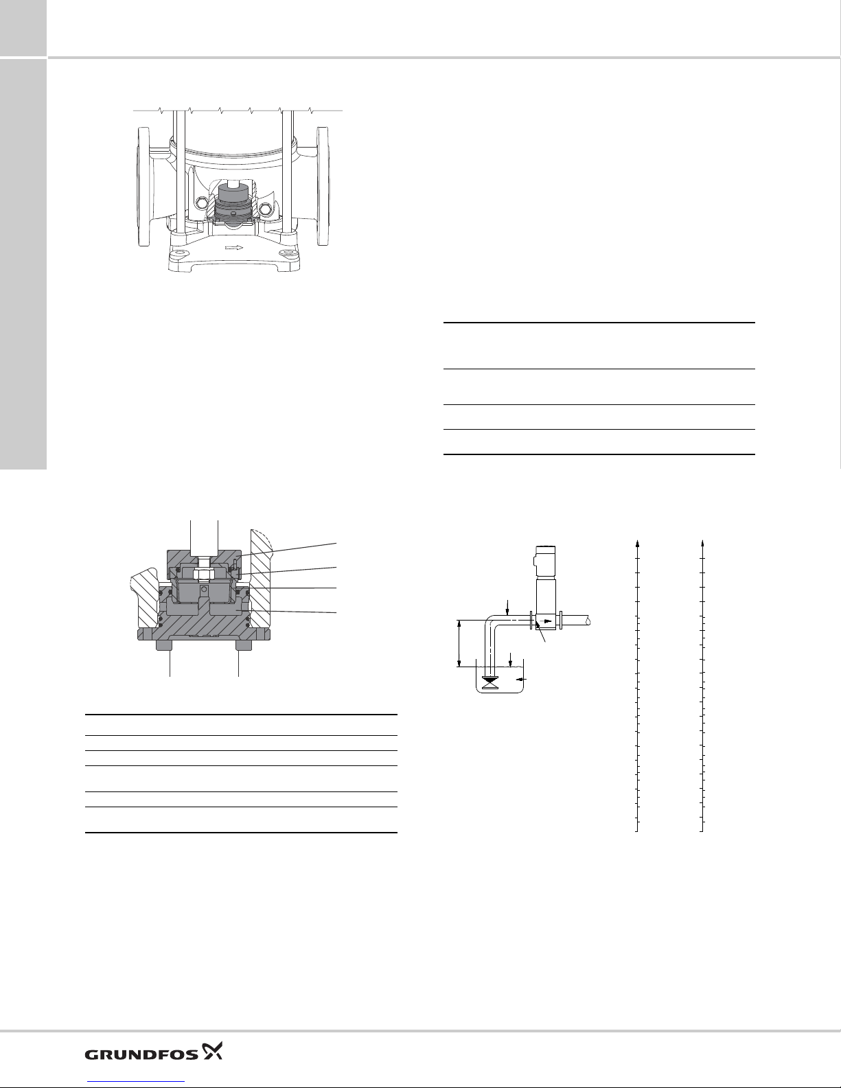
Thrust handling device
Minimum inlet pressure, NPSH
We recommend that you calculate the inlet pressure
"H" in these situations:
• The liquid temperature is high.
• The flow rate is significantly higher than the rated
flow rate.
• Water is drawn from depths.
• Water is drawn through long pipes.
• Inlet conditions are poor.
To avoid cavitation, make sure that there is a minimum
pressure on the inlet side of the pump.
TM06 9669 2817TM06 9670 2817
Fig. 12 Thrust handling device
A thrust handling device (THD) is factory-fitted on
pumps with 100 Hp (75 kW) motors or larger. The
system consists of two parts. A rotating part mounted
on the shaft end below the first impeller as well as a
non-rotating part mounted in or on the pump base.
The THD absorbs the main part of the thrust force
generated by the impellers and thereby reduces the
resulting axial force the motor bearings must absorb.
This enables the use of standard ball bearings in the
motor instead of special angular contact ball bearings.
Note: For applications involving CIP
(cleaning-in-place) and motors above 75 Hp (55 kW),
use a bearing flange and a base without THD.
Calculate the maximum suction lift "H" in m head as
follows:
x 10.2 - NPSH - Hf - H
H = p
b
p
=
b
NPSH =
H
=
f
H
=
v
Barometric pressure in ft (bar).
Barometric pressure can be set to 39.9 ft (1 bar).
In closed systems, p
feet (bar).
Net Positive Suction Head in ft (m) head, to be read from
the NPSH curve at the highest flow the pump will be
delivering.
Friction loss in inlet pipe in ft (m) head at the highest
flow the pump will be delivering.
Vapor pressure in ft (m) head, to be read from the vapor
pressure scale. H
v
indicates the system pressure in
b
depends on the liquid temperature tm.
v
If the calculated "H" is positive, the pump can operate
at a suction lift of maximum "H" ft (m) head.
If the calculated "H" is negative, an inlet pressure of
minimum "H" ft (m) head is required.
Fig. 13 Position numbers for THD parts
Pos. Description Material
120a Thrust disc Stainless steel
120b Rotating ring Silicon carbide
16
120g Stationary ring
120h Lifting plate Stainless steel
- O-rings
* On request for CRN.
Operating pressure and inlet pressure
Do not exceed the limit values for these pressures:
• maximum operating pressure
• maximum inlet pressure.
Silicon carbide*
Tungsten carbide
EPDM
FKM
TM02 7439 3403 - TM02 7445 3503
Fig. 14 Minimum inlet pressure, NPSH
Note: To avoid cavitation, do not select a pump with a
duty point too far to the right on the NPSH curve.
Always check the NPSH value of the pump at the
highest possible flow rate.
Page 17
CR, CRN 95-155
0 50 100 150 200 250 300 350 400 450 500 550 600
Q [US GPM]
0
50
100
150
200
250
300
350
400
450
500
550
600
650
700
[ft]
H
0 20 40 60 80 100 120 140
Q [m³/h]
0
20
40
60
80
100
120
140
160
180
200
[m]
H
CRN 95
60 Hz
ISO 9906:2012 Grade 3B
-5-2
-5-1
-1
-1-1
-2
-2-1
-2-2
-3
-3-1
-3-2
-4
-4-2
-4-1
0 50 100 150 200 250 300 350 400 450 500 550 600
Q [US GPM]
0
5
10
15
20
[hp]
P2
0
20
40
60
80
[%]
Eff
0
4
8
12
[kW]
P2
P2
1/1
IS 3550 rpm
P2
2/3
IS 3550 rpm
Eff 3550 rpm
0 50 100 150 200 250 300 350 400 450 500 550 600
Q [US GPM]
0
40
80
120
160
[ft]
H
0
10
20
30
40
[m]
H
0
10
20
30
40
[ft]
NPSH
0
2
4
6
8
10
12
[m]
QH
1/1
IS 3550 rpm
QH
2/3
IS 3550 rpm
NPSH 3550 rpm
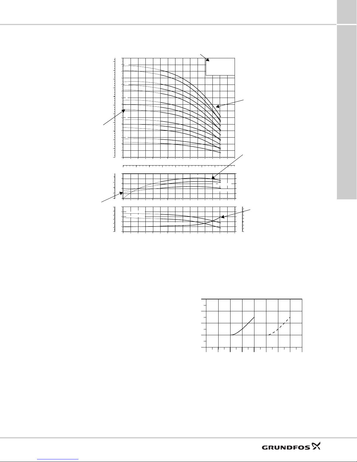
Pump type, frequency and ISO standard.
Number of stages.
First figure: number of stages.
Second figure: number of
reduced-diameter impellers.
The power curves indicate pump
input power per stage.
Curves are shown for complete
(1/1) and for reduced-diameter
(2/3) impellers.
QH curve for the individual pump.
The bold curves indicate the
recommended duty range for
best efficiency.
The eta curve shows the efficiency
of a pump with three full size
impellers.
The efficiency of pumps with
reduced-diameter impellers is
approximately 2 % lower than the
eta curve shown in the chart.
The NPSH curve is a maximum
curve for all the variants shown.
104 140 176 212 248 284 320 356
0
10
20
30
Qmin
(40) (60) (80) (120) (140) (160) (180)(100)
[ % ]
t
[°F]
[(°C)]
How to read the curve charts
4
Selection and sizing
Fig. 15 How to read the curve charts
Guidelines to performance curves
The guidelines below apply to the curves shown on the
following pages:
• Tolerances to ISO 9906:2012, Grade 3B, if
indicated.
• The motors used for the measurements are
standard Grundfos motors.
• Measurements have been made with airless water
at a temperature of 68 °F (20 °C).
• The curves apply to the following kinematic
viscosity: = 1 mm
2
/s (1 cSt).
• Due to the risk of overheating, the pumps must not
be used at a flow rate below the minimum flow rate.
• The QH curves apply to a rated motor speed of a
three-phase mains-operated motor. For realistic
curves, go to Grundfos Product Center
(http://product-selection.grundfos.com/) and insert
data.
The curve below shows the minimum flow rate as a
percentage of the rated flow rate in relation to the
liquid temperature. The dotted line shows a CR pump
fitted with an air-cooled top assembly.
Fig. 16 Minimum flow rate
TM06 5538 3718
TM07 0517 0118
17
Page 18

0 50 100 150 200 250 300 350 400 450 500 550 600
Q [US GPM]
0
50
100
150
200
250
300
350
400
450
500
550
600
650
700
[ft]
H
0 20 40 60 80 100 120 140
Q [m³/h]
0
20
40
60
80
100
120
140
160
180
200
[m]
H
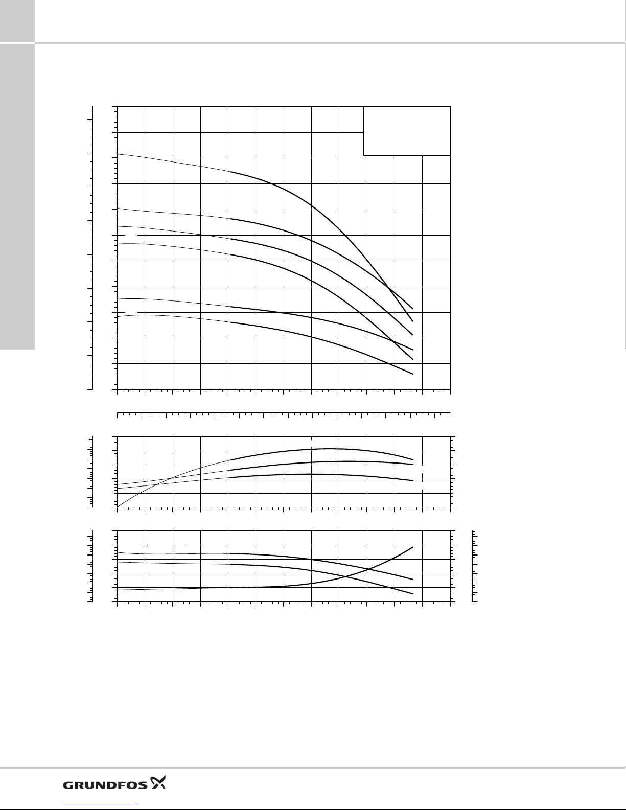
CR 95
60 Hz
ISO 9906:2012 Grade 3B
-5-1
-5-2
-1
-1-1
-2
-2-1
-2-2
-3
-3-1
-4
-3-2
-4-2
-4-1
0 50 100 150 200 250 300 350 400 450 500 550 600
Q [US GPM]
0
5
10
15
20
[hp]
P2
0
20
40
60
80
[%]
Eff
0
4
8
12
[kW]
P2
P2
1/1
IS 3550 rpm
P2
2/3
IS 3550 rpm
Eff 3550 rpm
0 50 100 150 200 250 300 350 400 450 500 550 600
Q [US GPM]
0
40
80
120
160
[ft]
H
0
10
20
30
40
[m]
H
0
10
20
30
40
[ft]
NPSH
0
2
4
6
8
10
12
[m]
QH
1/1
IS 3550 rpm
QH
2/3
IS 3550 rpm
NPSH 3550 rpm
5
CR 95
CR 95
5. Performance curves and technical data
CR 95
CR, CRN 95-155Performance curves and technical data
18
The maximum pump efficiency (Eta) is based on a three-stage pump.
TM06 5537 3718
Page 19

CR, CRN 95-155 Performance curves and technical data
B2
D2
D3
D1
G 1/2
G 1/2
G 1/2
G 1/2
B1
8 x ø0.75"
(8 x ø19.1)
(ø100)
ø4"
(225)
8.86"
(275)
10.83"
(380)
14.96"
(350)
13.78"
(419)
16.5"
(ø100)
ø4"
(350)
13.78"
(419)
16.5"
(4 x ø18.5)
4 x ø0.73"
(ø157)
ø6.19"
ø7.5"
(ø190)
ø9"
(ø229)
8 x ø0.88"
(8 x ø22.4)
(4 x ø18.5)
4 x ø0.73"
(ø157)
ø6.19"
ø7.88"
(ø200)
ø10"
(ø254)
(140)
5.51"
Class 300*
4" ANSI
Class 150*
4" ANSI
CR 95
5
CR 95
* CR, CRN 95 pumps with 1 to 4 stages (with 1 reduced diameter impeller) are fitted with 150 lb. (68 kg) flanges as standard. 300 lb.(136 kg) flanges
are available on request.
CR, CRN 95 pumps with 4 or more full diameter impellers are fitted with 300 lb. (136 kg) flanges as standard.
Dimensions and weights
Motor P
Pump type
CR 95-1-1 15 (11) 27.4 (696) 46.2 (1174) 12.4 (314) 8 (204) 8.5 (216) 412 (187)
CR 95-1 20 (15) 27.4 (696) 46.2 (1174) 12.4 (314) 8 (204) 8.5 (216) 412 (187)
CR 95-2-2 25 (18) 31.5 (800) 54.3 (1378) 12.4 (314) 8 (204) 10.5 (267) 452 (205)
CR 95-2-1 30 (22) 31.5 (800) 54.3 (1378) 12.4 (314) 8 (204) 10.5 (267) 478 (217)
CR 95-2 30 (22) 31.5 (800) 54.3 (1378) 12.4 (314) 8 (204) 10.5 (267) 478 (217)
CR 95-3-2 40 (30) 36.4 (925) 64 (1625) 16.9 (429) 14.1 (359) 12.5 (318) 739 (335)
CR 95-3-1 50 (37) 36.4 (925) 64 (1625) 16.9 (429) 14.1 (359) 12.5 (318) 807 (366)
CR 95-3 50 (37) 36.4 (925) 64 (1625) 16.9 (429) 14.1 (359) 12.5 (318) 807 (366)
CR 95-4-2 60 (45) 40.5 (1029) 67.6 (1716) 16.9 (429) 14.1 (359) 12.5 (318) 871 (395)
CR 95-4-1 60 (45) 40.5 (1029) 67.6 (1716) 16.9 (429) 14.1 (359) 12.5 (318) 871 (395)
CR 95-4 75 (56) 40.5 (1029) 68.1 (1729) 19.7 (500) 18.1 (460) 12.5 (318) 1190 (540)
CR 95-5-2 75 (56) 44.6 (1134) 72.2 (1834) 19.7 (500) 18.1 (460) 12.5 (318) 1204 (546)
CR 95-5-1 75 (56) 44.6 (1134) 72.2 (1834) 19.7 (500) 18.1 (460) 12.5 (318) 1204 (546)
[Hp (kW)]
2
B1 B1+B2 D1 D2 D3
Dimension [inch (mm)]
Net weight
[lbs (kg)]
TM06 6059 0218
19
Page 20

5
0 50 100 150 200 250 300 350 400 450 500 550 600
Q [US GPM]
0
50
100
150
200
250
300
350
400
450
500
550
600
650
700
[ft]
H
0 20 40 60 80 100 120 140
Q [m³/h]
0
20
40
60
80
100
120
140
160
180
200
[m]
H
CRN 95
60 Hz
ISO 9906:2012 Grade 3B
-5-2
-5-1
-1
-1-1
-2
-2-1
-2-2
-3
-3-1
-3-2
-4
-4-2
-4-1
0 50 100 150 200 250 300 350 400 450 500 550 600
Q [US GPM]
0
5
10
15
20
[hp]
P2
0
20
40
60
80
[%]
Eff
0
4
8
12
[kW]
P2
P2
1/1
IS 3550 rpm
P2
2/3
IS 3550 rpm
Eff 3550 rpm
0 50 100 150 200 250 300 350 400 450 500 550 600
Q [US GPM]
0
40
80
120
160
[ft]
H
0
10
20
30
40
[m]
H
0
10
20
30
40
[ft]
NPSH
0
2
4
6
8
10
12
[m]
QH
1/1
IS 3550 rpm
QH
2/3
IS 3550 rpm
NPSH 3550 rpm
CR, CRN 95-155Performance curves and technical data
CRN 95
CRN 95
CRN 95
20
The maximum pump efficiency (Eta) is based on a three-stage pump.
TM06 5538 3718
Page 21

CR, CRN 95-155 Performance curves and technical data
13.78"
16.5"
4 x ø0.73"
G 1/2
G 1/2
8.86"
ø4"
10.83"
14.96"
5.51"
4.49"
B2
D2
D3
D1
G 1/2
G 1/2
G 1/2
G 1/2
B1
8 x ø0.75"
(8 x ø19.1)
(ø100)
ø4"
(225)
(225)
8.86"
(275)
(275)
10.83"
(380)
(380)
14.96"
(350)
13.78"
(419)
16.5"
(ø100)
ø4"
(350) (350)
(ø100)
13.78"
(419)
(419)
16.5"
(4 x ø18.5)
4 x ø0.73"
(ø157)
ø6.19"
ø7.5"
(ø190)
ø9"
(ø229)
8 x ø0.88"
(8 x ø22.4)
(4 x ø18.5)
(4 x ø18.5)
4 x ø0.73"
(ø157)
ø6.19"
ø7.88"
(ø200)
ø10"
(ø254)
(140)
(140)
(114)
5.51"
Class 300*
4" ANSI
Class 150*
4" ANSI
P (PJE) Victaulic type
CRN 95
5
CRN 95
* CR, CRN 95 pumps with 1 to 4 stages (with 1 reduced diameter impeller) are fitted with 150 lb. (68 kg) flanges as standard. 300 lb. (136 kg) flanges
are available on request.
CR, CRN 95 pumps with 4 or more full diameter impellers are fitted with 300 lb.
(136 kg) flanges as standard.
Dimensions and weights
Motor P
Pump type
CRN 95-1-1 15 (11) 27.4 (696) 46.2 (1174) 12.4 (314) 8 (204) 8.5 (216) 412 (187)
CRN 95-1 20 (15) 27.4 (696) 46.2 (1174) 12.4 (314) 8 (204) 8.5 (216) 412 (187)
CRN 95-2-2 25 (18) 31.5 (800) 54.3 (1378) 12.4 (314) 8 (204) 10.5 (267) 452 (205)
CRN 95-2-1 30 (22) 31.5 (800) 54.3 (1378) 12.4 (314) 8 (204) 10.5 (267) 478 (217)
CRN 95-2 30 (22) 31.5 (800) 54.3 (1378) 12.4 (314) 8 (204) 10.5 (267) 478 (217)
CRN 95-3-2 40 (30) 36.4 (925) 64 (1625) 16.9 (429) 14.1 (359) 12.5 (318) 739 (335)
CRN 95-3-1 50 (37) 36.4 (925) 64 (1625) 16.9 (429) 14.1 (359) 12.5 (318) 807 (366)
CRN 95-3 50 (37) 36.4 (925) 64 (1625) 16.9 (429) 14.1 (359) 12.5 (318) 807 (366)
CRN 95-4-2 60 (45) 40.5 (1029) 67.6 (1716) 16.9 (429) 14.1 (359) 12.5 (318) 871 (395)
CRN 95-4-1 60 (45) 40.5 (1029) 67.6 (1716) 16.9 (429) 14.1 (359) 12.5 (318) 871 (395)
CRN 95-4 75 (56) 40.5 (1029) 68.1 (1729) 19.7 (500) 18.1 (460) 12.5 (318) 1190 (540)
CRN 95-5-2 75 (56) 44.6 (1134) 72.2 (1834) 19.7 (500) 18.1 (460) 12.5 (318) 1204 (546)
CRN 95-5-1 75 (56) 44.6 (1134) 72.2 (1834) 19.7 (500) 18.1 (460) 12.5 (318) 1204 (546)
[Hp (kW)]
2
B1 B1+B2 D1 D2 D3
Dimension [inch (mm)]
Net weight
[lbs (kg)]
TM06 6060 0319
21
Page 22

5
0 50 100 150 200 250 300 350 400 450 500 550 600 650 700 750 800
Q [US GPM]
0
50
100
150
200
250
300
350
400
450
500
550
[ft]
H
0 20 40 60 80 100 120 140 160 180
Q [m³/h]
0
20
40
60
80
100
120
140
160
[m]
H
CR 125
60 Hz
ISO 9906:2012 Grade 3B
-4-2
-1
-1-1
-2
-2-1
-2-2
-3
-3-1
-3-2
0 50 100 150 200 250 300 350 400 450 500 550 600 650 700 750 800
Q [US GPM]
0
10
20
30
40
[hp]
P2
0
20
40
60
80
[%]
Eff
0
5
10
15
20
25
[kW]
P2
P2
1/1
IS 3550 rpm
P2
2/3
IS 3550 rpm
Eff 3550 rpm
0 50 100 150 200 250 300 350 400 450 500 550 600 650 700 750 800
Q [US GPM]
0
40
80
120
160
[ft]
H
0
10
20
30
40
[m]
H
0
10
20
30
40
[ft]
NPSH
0
2
4
6
8
10
12
[m]
QH
1/1
IS 3550 rpm
QH
2/3
IS 3550 rpm
NPSH 3550 rpm
CR, CRN 95-155Performance curves and technical data
CR 125
CR 125
CR 125
22
The maximum pump efficiency (Eta) is based on a three-stage pump.
TM06 5539 3718
Page 23

CR, CRN 95-155 Performance curves and technical data
B2
D2
D3
D1
G 1/2
G 1/2
G 1/2
G 1/2
B1
(8 x ø22.2)
(12 x ø22.2)
8 x ø0.88"
12 x ø0.88"
(4 x ø22.6)
(4 x ø22.6)
4 x ø0.89"
4 x ø0.89"
ø6"
(ø150)
ø6"
(425)
16.83"
(499)
19.65"
(275)
10.83"
(332)
13.07"
(485)
19.09"
(425)
16.83"
(499)
19.65"
(ø216)
ø8.5"
ø8.5"
(ø216)
(ø270)
(ø328)
(180)
7.09"
(ø241)
ø9.5"
ø10.62"
ø12.8"
(ø300)
ø12.9"
(ø150)
Class 300*
6" ANSI
Class 150*
6" ANSI
CR 125
5
CR 125
* CR, CRN 125 pumps with 1 to 3 stages are fitted with 150 lb. (68 kg) flanges as standard. 300 lb. (136 kg) flanges are available on request.
CR, CRN 125 pumps with 4 or more stages are fitted with 300 lb.
(136 kg) flanges as standard.
Dimensions and weights
Motor P
Pump type
CR 125-1-1 20 (15) 30.8 (783) 49.6 (1261) 12.4 (314) 8 (204) 8.5 (216) 478 (217)
CR 125-1 25 (18) 30.9 (785) 53.7 (1363) 12.4 (314) 8 (204) 10.5 (267) 518 (235)
CR 125-2-2 30 (22) 35.7 (907) 58.5 (1485) 12.4 (314) 8 (204) 10.5 (267) 569 (258)
CR 125-2-1 40 (30) 36.6 (930) 64.2 (1630) 16.9 (429) 14.1 (359) 12.5 (318) 820 (372)
CR 125-2 50 (37) 36.6 (930) 64.2 (1630) 16.9 (429) 14.1 (359) 12.5 (318) 888 (403)
CR 125-3-2 60 (45) 41.4 (1052) 68.5 (1739) 16.9 (429) 14.1 (359) 12.5 (318) 961 (436)
CR 125-3-1 75 (56) 41.4 (1052) 69 (1752) 19.7 (500) 18.1 (460) 12.5 (318) 1281 (581)
CR 125-3 75 (56) 41.4 (1052) 69 (1752) 19.7 (500) 18.1 (460) 12.5 (318) 1281 (581)
CR 125-4-2 75 (56) 46.2 (1174) 73.8 (1874) 19.7 (500) 18.1 (460) 12.5 (318) 1303 (591)
[Hp (kw)]
2
B1 B1+B2 D1 D2 D3
Dimension [inch (mm)]
Net weight
TM06 6061 0218
[lbs (kg)]
23
Page 24

5
0 50 100 150 200 250 300 350 400 450 500 550 600 650 700 750 800
Q [US GPM]
0
50
100
150
200
250
300
350
400
450
500
550
600
650
700
750
800
850
900
950
1000
1050
[ft]
H
0 20 40 60 80 100 120 140 160 180
Q [m³/h]
0
20
40
60
80
100
120
140
160
180
200
220
240
260
280
300
320
[m]
H
CRN 125
60 Hz
ISO 9906:2012 Grade 3B
-3-1
-4-1
-5-1
-6-1
-4
-4-2
-5
-5-2
-6
-6-2
-7-2
-1
-1-1
-2
-2-1
-2-2
-3
-3-2
0 50 100 150 200 250 300 350 400 450 500 550 600 650 700 750 800
Q [US GPM]
0
10
20
30
40
[hp]
P2
0
20
40
60
80
[%]
Eff
0
5
10
15
20
25
[kW]
P2
P2
1/1
IS 3550 rpm
P2
2/3
IS 3550 rpm
Eff 3550 rpm
0 50 100 150 200 250 300 350 400 450 500 550 600 650 700 750 800
Q [US GPM]
0
40
80
120
160
[ft]
H
0
10
20
30
40
[m]
H
0
10
20
30
40
[ft]
NPSH
0
2
4
6
8
10
12
[m]
QH
1/1
IS 3550 rpm
QH
2/3
IS 3550 rpm
NPSH 3550 rpm
CR, CRN 95-155Performance curves and technical data
CRN 125
CRN 125
CRN 125
24
The maximum pump efficiency (Eta) is based on a three-stage pump.
TM06 5540 3718
Page 25

CR, CRN 95-155 Performance curves and technical data
16.83"
19.65"
4 x ø0.89"
G 1/2
G 1/2
10.83"
13.07"
ø6"
19.09"
7.09"
B2
D2
D3
D1
G 1/2
G 1/2
G 1/2
G 1/2
B1
(8 x ø22.2)
(12 x ø22.2)
8 x ø0.87"
12 x ø0.88"
(4 x ø22.6)
(4 x ø22.6)
(4 x ø22.6)
4 x ø0.89"
4 x ø0.89"
ø6"
(ø150)
ø6"
(425)
16.83"
(499)
19.65"
(275)
(275)
10.83"
(332)
(332)
13.07"
(485)
(485)
19.09"
(425)
(425)
16.83"
(499)
(499)
19.65"
(ø216)
ø8.5"
ø8.5"
(ø216)
(ø270)
(ø328)
(180)
(180)
6.63"
(168)
7.09"
(ø241)
ø9.5"
ø10.62"
ø11.8"
(ø300)
ø12.9"
(ø150)
(ø150)
Class 300*
6" ANSI
Class 150*
6" ANSI
P (PJE) Victaulic type
CRN 125
5
CRN 125
* CR, CRN 125 pumps with 1 to 3 stages are fitted with 150 lb. (68 kg) flanges as standard. 300 lb. (136 kg) flanges are available on request.
CR, CRN 125 pumps with 4 or more stages are fitted with 300 lb.
(136 kg) flanges as standard.
Dimensions and weights
Motor P
Pump type
CRN 125-1-1 20 (15) 30.8 (783) 49.6 (1261) 12.4 (314) 8 (204) 8.5 (216) 478 (217)
CRN 125-1 25 (18) 30.9 (785) 53.7 (1363) 12.4 (314) 8 (204) 10.5 (267) 518 (235)
CRN 125-2-2 30 (22) 35.7 (907) 58.5 (1485) 12.4 (314) 8 (204) 10.5 (267) 569 (258)
CRN 125-2-1 40 (30) 36.6 (930) 64.2 (1630) 16.9 (429) 14.1 (359) 12.5 (318) 820 (372)
CRN 125-2 50 (37) 36.6 (930) 64.2 (1630) 16.9 (429) 14.1 (359) 12.5 (318) 888 (403)
CRN 125-3-2 60 (45) 41.4 (1052) 68.5 (1739) 16.9 (429) 14.1 (359) 12.5 (318 ) 961 (436)
CRN 125-3-1 75 (56) 41.4 (1052) 69 (1752) 19.7 (500) 18.1 (460) 12.5 (318) 1281 (581)
CRN 125-3 75 (56) 41.4 (1052) 69 (1752) 19.7 (500) 18.1 (460) 12.5 (318) 1281 (581)
CRN 125-4-2 75 (56) 46.2 (1174) 73.8 (1874) 19.7 (500) 18.1 (460) 12.5 (318) 1303 (591)
CRN 125-4-1 100 (75) 46.1 (1172) 82.2 (2087) 22.2 (565) 19.2 (488) 18 (457) 1781 (808)
CRN 125-4 100 (75) 46.1 (1172) 82.2 (2087) 22.2 (565) 19.2 (488) 18 (457) 1781 (808)
CRN 125-5-2 100 (75) 50.9 (1294) 87 (2209) 22.2 (565) 19.2 (488) 18 (457) 1803 (818)
CRN 125-5-1 125 (93) 50.9 (1294) 90.6 (2300) 26.5 (673) 22.7 (576) 18 (457) 2255 (1023)
CRN 125-5 125 (93) 50.9 (1294) 90.6 (2300) 2 6.5 (673) 22.7 (576) 18 (457) 2255 (1023)
CRN 125-6-2 125 (93) 55.7 (1416) 95.4 (2422) 26.5 (673) 22.7 (576) 18 (457) 2280 (1034)
CRN 125-6-1 150 (112) 55.7 (1416) 95.4 (2422) 26.5 (673) 22.7 (576) 18 (457) 2511 (1139)
CRN 125-6 150 (112) 55.7 (1416) 95.4 (2422) 26.5 (673) 22.7 (576) 18 (457) 2511 (1139)
CRN 125-7-2 150 (112) 60.6 (1538) 100.2 (2544) 26.5 (673) 22.7 (576) 18 (457) 2533 (1149)
[Hp (kW)]
2
B1 B1+B2 D1 D2 D3
Dimension [inch (mm)]
Net weight
[lbs (kg)]
TM06 6062 0218
25
Page 26
5
0 100 200 300 400 500 600 700 800 900 1000
Q [US GPM]
0
50
100
150
200
250
300
350
400
450
500
[ft]
H
0 20 40 60 80 100 120 140 160 180 200 220 240
Q [m³/h]
0
20
40
60
80
100
120
140
160
[m]
H
CR 155
60 Hz
ISO 9906:2012 Grade 3B
-3-2
-1
-1-1
-2
-2-1
-2-2
0 100 200 300 400 500 600 700 800 900 1000
Q [US GPM]
0
10
20
30
40
[hp]
P2
0
20
40
60
80
[%]
Eff
0
5
10
15
20
25
[kW]
P2
P2
1/1
IS 3550 rpm
P2
2/3
IS 3550 rpm
Eff 3550 rpm
0 100 200 300 400 500 600 700 800 900 1000
Q [US GPM]
0
50
100
150
200
[ft]
H
0
10
20
30
40
50
60
[m]
H
0
10
20
30
40
[ft]
NPSH
0
2
4
6
8
10
12
[m]
QH
1/1
IS 3550 rpm
QH
2/3
IS 3550 rpm
NPSH 3550 rpm
CR, CRN 95-155Performance curves and technical data
CR 155
CR 155
CR 155
26
The maximum pump efficiency (Eta) is based on a three-stage pump.
TM06 5541 3718
Page 27

CR, CRN 95-155 Performance curves and technical data
B2
D2
D3
D1
G 1/2
G 1/2
G 1/2
G 1/2
B1
(8 x ø22.2)
(12 x ø22.2)
8 x ø0.88"
12 x ø0.88"
(4 x ø22.6)
(4 x ø22.6)
4 x ø0.89"
4 x ø0.89"
ø6"
(ø150)
ø6"
(425)
16.83"
(499)
19.65"
(275)
10.83"
(332)
13.07"
(485)
19.09"
(425)
16.83"
(499)
19.65"
(ø216)
ø8.5"
ø8.5"
(ø216)
(ø270)
(ø328)
(180)
7.09"
(ø241)
ø9.5"
ø10.62"
ø12.8"
(ø300)
ø12.9"
(ø150)
Class 300*
6" ANSI
Class 150*
6" ANSI
CR 155
5
CR 155
* CR, CRN 155 pumps with 1 to 3 stages (with 1 reduced diameter impeller) are fitted with 150 lb. (68 kg) flanges as standard. 300 lb. (136 kg) flanges
are available on request.
CR, CRN 155 pumps with 3 or more full diameter impellers are fitted with 300 lb. (136 kg) flanges as standard.
Dimensions and weights
Motor P
Pump type
CR 155-1-1 25 (18) 30.9 (785) 53.7 (1363) 12.4 (314) 8 (204) 10.5 (267) 520 (236)
CR 155-1 40 (30) 31.8 (808) 59.4 (1508) 16.9 (429) 14.1 (359) 12.5 (318) 798 (362)
CR 155-2-2 50 (37) 36.6 (930) 64.2 (1630) 16.9 (429) 14.1 (359) 12.5 (318) 888 (403)
CR 155-2-1 60 (45) 36.6 (930) 63.7 (1617) 16.9 (429) 14.1 (359) 12.5 (318) 939 (426)
CR 155-2 75 (56) 36.6 (930) 64.2 (1630) 19.7 (500) 18.1 (460) 12.5 (318) 1259 (571)
CR 155-3-2 75 (56) 41.4 (1052) 69 (1752) 19.7 (500) 18.1 (460) 12.5 (318) 1283 (582)
[Hp (kW)]
2
B1 B1+B2 D1 D2 D3
Dimension [inch (mm)]
Net weight
[lbs (kg)]
TM06 6061 0218
27
Page 28

5
0 100 200 300 400 500 600 700 800 900 1000
Q [US GPM]
0
50
100
150
200
250
300
350
400
450
500
550
600
650
700
750
800
850
[ft]
H
0 20 40 60 80 100 120 140 160 180 200 220 240
Q [m³/h]
0
20
40
60
80
100
120
140
160
180
200
220
240
260
[m]
H
CRN 155
60 Hz
ISO 9906:2012 Grade 3B
-3-1
-4-1
-5-2
-3
-3-2
-4
-4-2
-5-1
-1
-1-1
-2
-2-1
-2-2
0 100 200 300 400 500 600 700 800 900 1000
Q [US GPM]
0
10
20
30
40
[hp]
P2
0
20
40
60
80
[%]
Eff
0
5
10
15
20
25
[kW]
P2
P2
1/1
IS 3550 rpm
P2
2/3
IS 3550 rpm
Eff 3550 rpm
0 100 200 300 400 500 600 700 800 900 1000
Q [US GPM]
0
50
100
150
200
[ft]
H
0
10
20
30
40
50
60
[m]
H
0
10
20
30
40
[ft]
NPSH
0
2
4
6
8
10
12
[m]
QH
1/1
IS 3550 rpm
QH
2/3
IS 3550 rpm
NPSH 3550 rpm
CR, CRN 95-155Performance curves and technical data
CRN 155
CRN 155
CRN 155
28
The maximum pump efficiency (Eta) is based on a three-stage pump.
TM06 5542 3718
Page 29

CR, CRN 95-155 Performance curves and technical data
16.83"
19.65"
4 x ø0.89"
G 1/2
G 1/2
10.83"
13.07"
ø6"
19.09"
7.09"
B2
D2
D3
D1
G 1/2
G 1/2
G 1/2
G 1/2
B1
(8 x ø22.2)
(12 x ø22.2)
8 x ø0.87"
12 x ø0.88"
(4 x ø22.6)
(4 x ø22.6)
(4 x ø22.6)
4 x ø0.89"
4 x ø0.89"
ø6"
(ø150)
ø6"
(425)
16.83"
(499)
19.65"
(275)
(275)
10.83"
(332)
(332)
13.07"
(485)
(485)
19.09"
(425)
(425)
16.83"
(499)
(499)
19.65"
(ø216)
ø8.5"
ø8.5"
(ø216)
(ø270)
(ø328)
(180)
(180)
6.63"
(168)
7.09"
(ø241)
ø9.5"
ø10.62"
ø11.8"
(ø300)
ø12.9"
(ø150)
(ø150)
Class 150*
6" ANSI
Class 300*
6" ANSI
P (PJE) Victaulic type
CRN 155
5
CRN 155
* CR, CRN 155 pumps with 1 to 3 stages (with 1 reduced diameter impeller) are fitted with 150 lb. (68 kg) flanges as standard. 300 lb. (136 kg) flanges
are available on request.
CR, CRN 155 pumps with 3 or more full diameter impellers are fitted with 300 lb. (136 kg) flanges as standard.
Dimensions and weights
Motor P
Pump type
CRN 155-1-1 25 (18) 30.9 (785) 53.7 (1363) 12.4 (314) 8 (204) 10.5 (267) 520 (236)
CRN 155-1 40 (30) 31.8 (808) 59.4 (1508) 16.9 (429) 14.1 (359) 12.5 (318) 798 (362)
CRN 155-2-2 50 (37) 36.6 (930) 64.2 (1630) 16.9 (429) 14.1 (359) 12.5 (318) 888 (403)
CRN 155-2-1 60 (45) 36.6 (930) 63.7 (1617) 16.9 (429) 14.1 (359) 12.5 (318) 939 (426)
CRN 155-2 75 (56) 36.6 (930) 64.2 (1630) 19.7 (500) 18.1 (460) 12.5 (318) 1259 (571)
CRN 155-3-2 75 (56) 41.4 (1052) 69 (1752) 19.7 (500) 18.1 (460) 12.5 (318) 1283 (582)
CRN 155-3-1 100 (75) 41.3 (1050) 77.4 (1965) 22.2 (565) 19.2 (488) 18 (457) 1761 (799)
CRN 155-3 100 (75) 41.3 (1050) 77.4 (1965) 22.2 (565) 19.2 (488) 18 (457) 1761 (799)
CRN 155-4-2 125 (93) 46.1 (1172) 85.7 (2178) 26.5 (673) 22.7 (576) 18 (457) 2238 (1015)
CRN 155-4-1 125 (93) 46.1 (1172) 85.7 (2178) 26.5 (673) 22.7 (576) 18 (457) 2238 (1015)
CRN 155-4 125 (93) 46.1 (1172) 85.7 (2178) 26.5 (673) 22.7 (576) 18 (457) 2238 (1015)
CRN 155-5-2 150 (112) 50.9 (1294) 90.6 (2300) 26.5 (673) 22.7 (576) 18 (457) 2493 (1131)
CRN 155-5-1 150 (112) 50.9 (1294) 90.6 (2300) 26.5 (673) 22.7 (576) 18 (457) 2493 (1131)
[Hp (kW)]
2
B1 B1+B2 D1 D2 D3
Dimension [inch (mm)]
Net weight
[lbs (kg)]
TM06 6062 0218
29
Page 30
6
Baldor motor Grundfos motor
Motor data
CR, CRN 95-155
6. Motor data
Standard motors, 60 Hz
TM06 6898 2616 - GR7845
Motor
P2
[Hp
(kW)]
15 (11) 254TC
20 (15) 254TC
25 (19) 284TSC
30 (22) 286TSC
40 (30) 324TSC 230/460 90/45 1.15 0.86
50 (37) 326TSC 230/460 112/56 1.15 0.87
60 (45) 364TSC 230/460 132/66 1.15 0.87
75 (56) 365TSC 230/460 166/83 1.15 0.87
100 (75) 405TSD 460 110 1.15 0.90
125 (93) 444TSD 460 137 1.15 0.90
150 (112) 445TSD 460 166 1.15 0.89
Frame
size
Standard
voltage
[V]
208-230DD/
460D
208-230DD/
460D
208-230DD/
460D
208-230DD/
460D
I
Service
1/1
[A]
37.5-34/17 1.15 0.91-0.89
50.5-46/23 1.15 0.92-0.90
62-56/28 1.15 0.92-0.91
74-67/33.5 1.15 0.92-0.91
factor
Cos φ
Efficiency class
1/1
NEMA Premium /
NEMA Premium /
NEMA Premium /
NEMA Premium /
NEMA Premium /
NEMA Premium /
NEMA Premium /
NEMA Premium /
NEMA Premium /
NEMA Premium /
NEMA Premium /
IE3 60Hz
IE3 60Hz
IE3 60Hz
IE3 60Hz
IE3 60Hz
IE3 60Hz
IE3 60Hz
IE3 60Hz
IE3 60Hz
IE3 60Hz
IE3 60Hz
η
[%]
IE3 91.0% 255-306/153 3490-3530
IE3 91.0% 308-373/186 3490-3530
IE3 91.7% 341-420/210 3490-3530
IE3 91.7% 400-489/245 3490-3530
IE3 92.4% 564/326 3540
IE3 93.0% 688/398 3540
IE3 93.6% 989/572 3550
IE3 93.6% 1210/700 3550
IE3 94.1% 695 3565
IE3 95.0% 848 3565
IE3 95.0% 978 3575
I
start
[A]
Speed
[rpm]
Motor
brand
Grundfos
Baldor
30
Page 31

CR, CRN 95-155
7. List of pumped liquids
A number of typical liquids are listed below.
Other pump versions may be applicable, but those
stated in the list are considered to be the best choices.
The table is intended as a general guide only and
cannot replace actual testing of the pumped liquids
and pump materials under specific working conditions.
Therefore, use the list with some caution. Factors such
as those mentioned below may affect the chemical
resistance of a specific pump version:
• concentration of the pumped liquid
• liquid temperature
• pressure.
Take safety precautions when pumping dangerous
liquids.
Notes
D Often with additives.
The density and/or viscosity differ from that/those of water.
E
Take this factor into account when calculating motor output and
pump performance.
F Pump selection depends on many factors. Contact Grundfos.
H Risk of crystallization/precipitation in shaft seal.
1 Highly flammable liquid.
2 Combustible liquid.
3 Insoluble in water.
4 Low self-ignition point.
7
List of pumped liquids
31
Page 32

7
List of pumped liquids
Pumped liquid Chemical formula Note
Acetic acid CH
Acetone CH
Alkaline degreasing agent D, F - HQQE Ammonium bicarbonate NH
Ammonium hydroxide NH
Aviation fuel 1, 3, 4, F 100 %, 68 °F (20 °C) HQBV Benzoic acid C
Boiler water
Calcareous water - < 194 °F (90 °C) HQQE Calcium acetate (as coolant with inhibitor) Ca(CH
Calcium hydroxide Ca (OH)
Chloride-containing water F
Chromic acid H
Citric acid HOC(CH
Completely desalinated water (demineralized
water)
Condensate - 248 °F (120 °C) HQQE Copper sulphate CuSO
Corn oil D, E, 3 100 %, 176 °F (80 °C) HQQV Diesel oil 2, 3, 4, F 100 %, 68 °F (20 °C) HQBV Domestic hot water (potable water) - < 248 °F (120 °C) HQQE Ethanol (ethyl alcohol) C
Ethylene glycol HOCH
Formic acid HCOOH - 5 %, 68 °F (20 °C) - HQQE
Glycerine (glycerol) OHCH
Hydraulic oil (mineral) E, 2, 3 100 %, 212 °F (100 °C) HQQV Hydraulic oil (synthetic) E, 2, 3 100 %, 212 °F (100 °C) HQQV Isopropyl alcohol CH
Lactic acid CH
Linoleic acid C
Methanol (methyl alcohol) CH
Motor oil E, 2, 3 100 %, 176 °F (80 °C) HQQV Naphthalene C
Nitric acid HNO
Oil-containing water - < 212 °F (100 °C) HQQV Olive oil D, E, 3 100 %, 176 °F (80 °C) HQQV Oxalic acid (COOH)
Ozone-containing water (O
Peanut oil D, E, 3 100 %, 176 °F (80 °C) HQQV Petrol 1, 3, 4, F 100 %, 68 °F (20 °C) HQBV Phosphoric acid H
Propanol C
Propylene glycol CH
Potassium carbonate K
Potassium formate (as coolant with inhibitor) KOOCH D, E 30 %, 122 °F (50 °C) HQQE Potassium hydroxide KOH E 20 %, 122 °F (50 °C) - HQQE
Potassium permanganate KMnO
Rape seed oil D, E, 3 100 %, 176 °F (80 °C) HQQV Salicylic acid C
Silicone oil E, 3 100 % HQQV Sodium bicarbonate NaHCO
Sodium chloride (as coolant) NaCl D, E 30 %, < 41 °F (5 °C), pH > 8 HQQE Sodium hydroxide NaOH E 20 %, 122 °F (50 °C) - HQQE
Sodium hypochlorite NaOCl F 0.1 %, 68 °F (20 °C) - HQQV
Sodium nitrate NaNO
Sodium phosphate Na
Sodium sulphate Na
Softened water - < 248 °F (120 °C) - HQQE
Soya oil D, E, 3 100 %, 176 °F (80 °C) HQQV Sulphuric acid H
Sulphurous acid H
Unsalted swimming-pool water - Approx. 2 ppm free chlorine (Cl
CR, CRN 95-155
Liquid concentration, liquid
temperature
COOH - 5 %, 68 °F (20 °C) - HQQE
3
COCH
3
3
HCO
4
3
OH - 20 %, 104 °F (40 °C) HQQE -
4
COOH H 0.5 %, 68 °F (20 °C) - HQQV
6H5
1, F 100 %, 68 °F (20 °C) - HQQE
E 20 %, 86 °F (86 °F (30 °C)) - HQQE
- < 248 °F (120 °C) HQQE -
F 248-356 °F (120-180 °C) - -
COO)
3
2
2
CrO
2
4
COOH H 5 %, 104 °F (40 °C) - HQQE
2CO2H)2
D, E 30 %, 122 °F (50 °C) HQQE -
E
Saturated solution, 122 °F (50
< 86 °F (30 °C), maximum 500
°C)
ppm
H 1 %, 68 °F (20 °C) - HQQV
- 248 °F (120 °C) - HQQE
4
OH 1, F 100 %, 68 °F (20 °C) HQQE -
2H5
OH D, E 50 %, 122 °F (50 °C) HQQE -
2CH2
CH(OH)CH2OH D, E 50 %, 122 °F (50 °C) HQQE -
2
CHOHCH
3
CH(OH)COOH E, H 10 %, 68 °F (20 °C) - HQQV
3
17H31
CH(OH)CH2OH D, E 50 %, 194 °F (90 °C) HQQE -
3
(OH)COOH H 0.1 %, 68 °F (20 °C) - HQQE
6H4
3
COOH E, 3 100 %, 68 °F (20 °C) HQQV OH 1, F 100 %, 68 °F (20 °C) HQQE -
3
10H8
3
2
) - < 212 °F (100 °C) - HQQE
3
3PO4
OH 1, F 100 %, 68 °F (20 °C) HQQE -
3H7
2CO3
4
3
3
3PO4
2SO4
2SO4
2SO3
E 10 %, 122 °F (50 °C) - HQQE
1, F 100 %, 68 °F (20 °C) HQQE -
E, H 100 %, 176 °F (80 °C) HQQV -
F 1 %, 68 °F (20 °C) - HQQE
H 1 %, 68 °F (20 °C) - HQQE
E 20 %, 68 °F (20 °C) - HQQE
E 20 %, 122 °F (50 °C) HQQE -
- 5 %, 68 °F (20 °C) - HQQE
E 10 %, 140 °F (60 °C) - HQQE
E 10 %, 140 °F (60 °C) - HQQE
E, H 10 %, 140 °F (60 °C) - HQQE
E, H 10 %, 140 °F (60 °C) - HQQE
F 1 %, 68 °F (20 °C) - HQQV
- 1 %, 68 °F (20 °C) - HQQE
CR CRN
HQQE -
- HQQE
) HQQE -
2
32
Page 33

CR, CRN 95-155
8. Accessories
PJE couplings for CRN
Materials in contact with the pumped liquid are made of stainless steel AISI 316 and rubber.
A set consists of two coupling halves (Victaulic
and nuts.
®
type 77), one gasket, one pipe stub (for welding or threaded), bolts
8
Accessories
Coupling Pump type Pipe stub
CRN 95 For welding 800 (55) 4"
CRN 125
CRN 155
For welding 800 (55) 6"
Max. pressure
[psi (bar)]
Pipe connection
Rubber
parts
EPDM
FKM
EPDM
FKM
Number of
coupling sets
required
2
2
33
Page 34

9
"REPLACEMENT" enables you to find a
replacement product. Search results will
include information on the following:
• the lowest purchase price
• the lowest energy consumption
• the lowest total life cycle cost.
"CATALOGUE" gives you
access to the Grundfos
product catalogue.
"LIQUIDS" enables you to find
pumps designed for aggressive,
flammable or other special
liquids.
Grundfos Product Center
9. Grundfos Product Center
Online search and sizing tool to help you
make the right choice.
http://product-selection.grundfos.com
This drop-down menu enables you to set the
search function to "Products" or "Literature".
"SIZING" enables you to size a
pump based on entered data and
selection choices.
CR, CRN 95-155
All the information you need in one place Downloads
Performance curves, technical specifications, pictures, dimensional drawings, motor
curves, wiring diagrams, spare parts, service kits, 3D drawings, documents, system parts.
The Product Center displays any recent and saved items - including complete projects right on the main page.
34
On the product pages, you can download
installation and operating instructions, data
booklets, service instructions, etc. in PDF format.
Page 35

CR, CRN 95-155
GET IT ON
Grundfos GO
Mobile solution for professionals on the GO!
Grundfos GO is the mobile tool box for professional
users on the go. It is the most comprehensive platform
for mobile pump control and pump selection including
sizing, replacement and documentation. It offers
intuitive, handheld assistance and access to Grundfos
online tools, and it saves valuable time for reporting
and data collection.
9
Grundfos Product Center
35
Page 36

99407996 0419
ECM: 1257564
Grundfos Kansas City
9300 Loiret Boulevard
Lenexa, Kansas 66219
Phone: 913-227-3400
Fax: 913-227-3500
www.grundfos.us
Grundfos Canada
2941 Brighton Road
Oakville, Ontario L6H 6C9 Canada
Phone: +1-905-829-9533
Fax: +1-905-829-9512
www.grundfos.ca
Grundfos México
Boulevard TLC No. 15
Parque Industrial Stiva Aeropuerto
C.P. 66600 Apodaca, N.L. Mexico
Phone: 011-52-81-8144 4000
Fax: 011-52-81-8144 4010
www.grundfos.mx
Trademarks displayed in this material, including but not limited to Grundfos, the Grundfos logo and “be think innovate” are registered trademarks owned by The Grundfos Group. All rights reserved. © 2019 Grundfos Holding A/S, all rights reserved.
 Loading...