

Page 1

Control MPC
Installation and operating instructions
GRUNDFOS INSTRUCTIONS
Page 2

Declaration of Conformity
We, Grundfos, declare under our sole responsibility that the products
Control MPC, to which this declaration relates, are in conformity with these
Council directives on the approximation of the laws of the EC member
states:
— Low Voltage Directive (2006/95/EC).
Standards used: EN 60439-1: 2002 and EN 60204-1: 2006.
— EMC Directive (2004/108/EC).
Attestation of conformity: Certificate Control MPC 2: 2009.
These products must not be put into service until the system into which
they are to be incorporated has been declared in conformity with the
provisions of the Machinery Directive (2006/42/EC).
Bjerringbro, 29th December 2009
Svend Aage Kaae
Technical Director
2
Page 3

CONTENTS
Page
1. Symbols used in this document 4
2. Scope of these instructions 4
3. Product description 4
4. Applications 4
4.1 Pumps 4
4.2 Control variant 4
5. Nameplate 5
6. Software label 5
7. Type key 6
8. Overview of control variants, examples 7
9. Installation 9
9.1 Mechanical installation 9
9.2 Electrical installation 9
9.3 Start-up 9
10. Control panel 9
10.1 Display (pos. 1) 10
10.1.1 Menu line 10
10.1.2 Top line 10
10.1.3 Graphical illustration 10
10.1.4 Scroll bar 10
10.1.5 Bottom line 10
10.2 Buttons and indicator lights 10
10.2.1 Arrow to the right (pos. 2) 10
10.2.2 Help (pos. 3) 10
10.2.3 Up and down (pos. 4 and 5) 10
10.2.4 Plus and minus (pos. 6 and 7) 10
10.2.5 Esc (pos. 8) 10
10.2.6 Home (pos. 9) 10
10.2.7 Ok (pos. 10) 10
10.2.8 Indicator lights (pos. 11 and 12) 10
10.2.9 Contrast (pos. 13) 10
10.2.10 Back light 10
11. Functions 11
11.1 Tree of functions 11
11.2 Overview 13
11.3 Description of functions 15
11. 4 Status (1) 1 5
11.4.1 Current alarms (3.1) 15
11.4.2 System (1.2) 15
11.4.3 Operating mode (1.2.1) 16
11.4.4 Setpoint (1.2.2) 16
11.4.5 Setpoint influence (1.2.3) 16
11.4.6 Measured values (1.2.4) 17
11.4.7 Analog inputs (1.2.5) 17
11.4.8 Pump 1...6 (1.3 to 1.8) 17
11.5 Operation (2) 18
11.5.1 Operation (2) 18
11.5.2 System operating mode (2.1.1) 18
11.5.3 Control mode (2.1.2) 19
11.5.4 Setpoints (2.1.3) 21
11.5.5 Individual pump control (2.1.4) 21
11.5.6 Setting of individual operating mode
(2.1.4.1 to 2.1.4.6) 22
11. 6 Al ar m ( 3) 23
11.6.1 Alarm status (3) 23
11.6.2 Current alarms (3.1) 24
11.6.3 Alarm log (3.2) 24
11.7 Settings (4) 25
11.7.1 Primary controller (4.1) 25
11.7.2 PI controller (4.1.1) 26
11.7.3 Alternative setpoints (4.1.2) 27
11.7.4 Alternative setpoints 2 to 7 (4.1.2.1 to 4.1.2.7) 27
11.7.5 External setpoint influence (4.1.3) 28
11.7.6 Setting of influence function (4.1.3.2) 29
11.7.7 Primary sensor (4.1.4) 29
11.7.8 Clock program (4.1.6) 30
11.7.9 Proportional pressure (4.1.7) 31
11.7.10 S-system configuration (4.1.8) 31
11.7.11 Pump cascade control (4.2) 32
11.7.12 Min. time between start/stop (4.2.1) 32
11.7.13 Max. number of starts/hour (4.2.1) 32
11.7.14 Standby pumps (4.2.3) 33
11.7.15 Forced pump changeover (4.2.4) 33
11.7.16 Pump test run (4.2.5) 34
11.7.17 Pilot pump (4.2.6) 34
11.7.18 Pump stop attempt (4.2.7) 35
11.7.19 Pump start and stop speed (4.2.8) 35
11.7.20 Min. performance (4.2.9) 36
11.7.21 Compensation for pump start-up time (4.2.10) 36
11.7.22 Secondary functions (4.3) 37
11.7.23 Stop function (4.3.1) 37
11.7.24 Soft pressure build-up (4.3.3) 39
11.7.25 Emergency run (4.3.5) 40
11.7.26 Digital inputs (4.3.7) 40
11.7.27 Functions of digital inputs (4.3.7.1) 41
11.7.28 Analog inputs (4.3.8) 41
11.7.29 Analog inputs (4.3.8.1 to 4.3.8.7) 42
11.7.30 Analog inputs and measured value
(4.3.8.1.1 to 4.3.8.7.1) 42
11.7.31 Digital outputs (4.3.9) 43
11.7.32 Functions of digital outputs (4.3.9.1 to 4.3.9.16) 43
11.7.33 Min., max. and user-defined duty (4.3.14) 44
11.7.34 Min. duty (4.3.14.1) 44
11.7.35 Max. duty (4.3.14.2) 45
11.7.36 User-defined duty (4.3.14.3) 45
11.7.37 Pump curve data (4.3.19) 46
11.7.38 Control source (4.3.20) 47
11.7.39 Fixed inlet pressure (4.3.22) 47
11.7.40 Flow estimation (4.3.23) 48
11.7.41 Monitoring functions (4.4) 48
11.7.42 Dry-running protection (4.4.1) 49
11.7.43 Dry-running protection with pressure/level switch
(4.4.1.1) 49
11.7.44 Dry-running protection with pressure transmitter
(4.4.1.2) 50
11.7.45 Dry-running protection with level transmitter
(4.4.1.3) 50
11.7.46 Min. pressure (4.4.2) 51
11.7.47 Max. pressure (4.4.3) 51
11.7.48 External fault (4.4.4) 52
11.7.49 Limit 1 and 2 exceeded (4.4.5 and 4.4.6) 52
11.7.50 Pumps outside duty range (4.4.7) 53
11.7.51 Pressure relief (4.4.8) 54
11.7.52 Functions, CU 351 (4.5) 55
11.7.53 Display language (4.5.1) 55
11.7.54 Display units (4.5.2) 56
11.7.55 Date and time (4.5.3) 57
11.7.56 Passwords (4.5.4) 57
11.7.57 Ethernet (4.5.5) 58
11.7.58 GENIbus number (4.5.6) 58
11.7.59 Software status (4.5.9) 58
11.8 Data communication 59
11.8.1 Ethernet 59
11.8.2 GENIbus 60
12. Measuring parameters 61
12.1 Transmitter types 61
12.2 Parameter list 61
13. Fault finding chart 62
14. Maintenance 63
14.1 CU 351 63
15. Taking out of operation 63
16. Technical data 63
16.1 Temperature 63
16.2 Relative humidity 63
17. Electrical data 63
18. Related documents 63
19. Disposal 63
3
Page 4

Warnin g
Caution
Note
Note
Prior to installation, read these installation and
operating instructions. Installation and operation
must comply with local regulations and accepted
codes of good practice.
4. Applications
Control MPC is used for control and monitoring of pumps in these
applications:
• booster systems
• circulation systems for heating, cooling and air-conditioning.
1. Symbols used in this document
Warnin g
If these safety instructions are not observed, it
may result in personal injury!
If these safety instructions are not observed, it
may result in malfunction or damage to the
equipment!
Notes or instructions that make the job easier
and ensure safe operation.
2. Scope of these instructions
These installation and operating instructions apply to Grundfos
Control MPC.
Grundfos Control MPC is a complete solution for control and
monitoring of up to six identical pumps.
3. Product description
4.1 Pumps
Control MPC is designed for systems with these pumps:
• CR(E), CRI(E), CRN(E), CRIE
• NB(E), NBG(E)
• NK(E), NKG(E)
•TP
• TPE Series 1000
• TPE Series 2000
•HS
•SP
• MAGNA, UPE Series 2000.
The main pumps of the system must be of the
same type and size.
4.2 Control variant
Control MPC is divided into four groups based on control variant:
Control
variant
Series
2000
See also section 8. Overview of control variants.
The Control MPC includes software for booster, heating and
cooling.
Description
Two to six electronically speed-controlled pumps.
From 0,37 to 22 kW, Control MPC-E is equipped with
Grundfos pumps with integrated frequency converter.
-E
As from 30 kW, Control MPC-E is equipped with
mains-operated pumps connected to external
Grundfos CUE frequency converters (one per pump).
Two to six MAGNA, UPE or TPE Series 2000 pumps
Two to six pumps connected to an external Grundfos
-F
CUE frequency converter. The speed-controlled
operation alternates between the pumps.
-S Two to six mains-operated pumps
TM04 0210 0208 - GrA5728
Fig. 1 Control MPC
Grundfos Control MPC is used for control and monitoring of
booster systems and circulation systems.
Control MPC consists of a control cabinet with a built-in controller,
the CU 351. The control cabinet contains all necessary
components such as main switch, contactors, IO modules and
cabling. In systems with external frequency converters, the
frequency converters can be installed in the cabinet.
The control cabinet is for wall or floor mounting.
4
Page 5

5. Nameplate
Type:
Model:
Serial No.:
Order No.:
Options:
IP
Weight: kg
Made in
96778609
1
2
3
4
78 9
16
17
23
24
26
25
Mains supply:
I
n
: A T
AMB.
:
o
C
PU
n
No. kW V
Fixed speed pumps:
E-pumps:
Pilot Pump:
10
11 12
18
20 21
19
22
13 14
15
5
6
Note
The nameplate of the Control MPC is fitted on the base frame.
See position 2 in fig. 2.
6. Software label
The software label is placed on the back of the CU 351 controller.
1. Control MPC 3. Hydro MPC
1
2
3
4. H-MPC options2. C-MPC options
4 5
5. Pump data
Fig. 2 Nameplate
Pos. Description
1 Type designation
2 Model
3 Serial number
4 Supply voltage
5 Nominal current [A]
6 Maximum ambient temperature in °C
7 Number of mains-operated pumps
8 Motor power in kW for mains-operated pumps
9 Nominal voltage in volts for mains-operated pumps
10 Number of pumps with frequency converter
11 Motor power in kW for pumps with frequency converter
Nominal voltage in volts for pumps with frequency
12
converter
13 Number of pilot pumps
14 Motor power in kW for pilot pump
15 Nominal voltage in volts for pilot pump
16 Order number
17-22 Options
23 Enclosure class
24 Weight [kg]
25 CE-mark
26 Country of origin
CONFIGURATION STEPS - PLEASE FOLLOW THE NUMBERS
Fig. 3 Software label
Pos. Description
1 Control MPC - GSC file number
2 Control MPC options - GSC file numbers
3 Hydro MPC - GSC file number*
4 Hydro MPC options - GSC file numbers*
5 Pump data - GSC file numbers**
* Applies only to booster systems.
** Applies only to CR, CRI, CRE and CRIE pumps.
A GSC (Grundfos Standard Configuration) file is a
TM03 9956 4707
configuration data file.
96586126
TM03 1742 3105
5
Page 6

7. Type key
Example Control MPC -E 2 x 4 E (* (* (* 3 x 380-415 V, 50/60 Hz, PE
Type range
Subgroups:
E: Pumps with integrated frequency converter (0.37 - 22 kW) - one per pump
E: Pumps with external Grundfos CUE frequency converter (30 kW and above) -
one per pump
F: Pumps with external Grundfos CUE frequency converter
S: Mains-operated pumps (start/stop)
Number of pumps with frequency converter
Power [kW]
Starting method:
E: Electronic soft starter (pumps with integrated frequency converter)
ESS: Electronic soft starter (pumps with external Grundfos CUE frequency converter)
Number of mains-operated pumps
Power [kW]
Starting method:
DOL: Direct-on-line starting
SD: Star-delta starting
Supply voltage, frequency
(* Code for custom-built solution.
6
Page 7

8. Overview of control variants
PTPTPT
Q
H
H
set
H
set
Q
H
H
stop
H
set
Q
H
H
set
H
set
Q
H
H
stop
H
set
The examples below are based on booster systems.
Systems with speed-controlled
pumps
Control MPC-E Control MPC-F Control MPC-S
Control MPC with three E-pumps.
One E-pump in operation.
Systems with pumps connected to
one CUE frequency conve rter
Control MPC with three pumps
connected to an external Grundfos CUE
frequency converter in the control
cabinet. The speed-controlled operation
alternates between the pumps.
TM03 0993 0905
One pump connected to an external
Grundfos CUE frequency converter in
operation.
H
Systems with mains-operated pumps
Control MPC with three mains-operated
pumps.
TM03 1265 1505
One mains-operated pump in operation.
TM03 0999 0905
Three E-pumps in operation.
• Control MPC-E maintains a constant
pressure through continuous adjustment
of the speed of the pumps.
• The system performance is adjusted to
the demand through cutting in/out the
required number of pumps and through
parallel control of the pumps in operation.
• Pump changeover is automatic and
depends on load, operating hours and
fault.
• All pumps in operation will run at equal
speed.
• The number of pumps in operation also
depends on the energy consumption of
the pumps. If only one pump is required,
two pumps will be running at a lower
speed if this results in a lower energy
consumption. This requires that the
differential pressure of the pump is
measured.
TM00 7995 2296
One pump connected to an external
Grundfos CUE frequency converter and
two mains-operated pumps in operation.
H
TM00 7996 2296
• Control MPC-F maintains a constant
pressure through continuous adjustment
of the speed of the pump connected to the
external Grundfos CUE frequency
converter. The speed-controlled operation
alternates between the pumps.
• One pump connected to the external
Grundfos CUE frequency converter
always starts first. If the pressure cannot
be maintained by the pump, one or two
mains-operated pumps will be cut in.
• Pump changeover is automatic and
depends on load, operating hours and
fault.
Q
TM00 7995 2296
Three mains-operated pumps in
operation.
Q
TM00 7998 2296
• Control MPC-S maintains an almost
constant pressure through cutting in/out
the required number of pumps.
• The operating range of the pumps will lie
between H
set
and H
(cut-out pressure).
stop
• Pump changeover is automatic and
depends on load, operating hours and
fault.
TM03 9204 3607
TM03 9203 3607
7
Page 8

The example below is based on a circulation system.
Q
H
H
set
Q
H
H
set
Control MPC Series 2000
Control MPC with three E-pumps.
TM04 0213 5107
One E-pump in operation.
TM04 0211 5107
Three E-pumps in operation.
• Control MPC Series 2000 maintains a
constant pressure through adjustment of
the speed of the pumps connected.
• The performance is adjusted to the demand
through cutting in/out the required number
of pumps and through parallel control of the
pumps in operation.
• Pump changeover is automatic and
depends on load, operating hours and fault.
• All pumps in operation will run at equal
speed.
• The number of pumps in operation is also
depending on the energy consumption of
the pumps. If only one pump is required,
the Control MPC will run with two pumps in
operation at a lower speed if this results in
a lower energy consumption. This requires
that the differential pressure of the pump is
measured.
TM04 0212 5107
8
Page 9

9. Installation
Note
Note
Warning
Installation and operation must comply with local
regulations and accepted codes of good
practice.
Before installation check that
• the Control MPC corresponds to the one ordered
• no visible parts have been damaged.
9.1 Mechanical installation
The Control MPC must be installed in a well ventilated room to
ensure sufficient cooling of the control cabinet.
Install the pumps according to the installation and operating
instructions supplied with the pumps.
Control MPC is not designed for outdoor
installation and must not be exposed to direct
sunlight.
9.2 Electrical installation
Warnin g
The electrical installation should be carried out
by an authorised person in accordance with local
regulations and the relevant wiring diagram.
• The electrical installation of the Control MPC must comply with
enclosure class, IP54.
• Make sure that the Control MPC is suitable for the electricity
supply to which it is connected.
• Make sure that the wire cross-section corresponds to the
specifications in the wiring diagram.
9.3 Start-up
The start-up description presupposes that the selected pumps
have been installed correctly according to the installation and
operating instructions supplied with the pumps.
After having carried out the installation of the Control MPC as
described in section 9. Installation, proceed as follows:
1. Turn on the electricity supply.
2. Wait for the first display to appear.
3. The first time the CU 351 is switched on, a start-up wizard will
guide the user through the basic settings.
4. Follow the instructions in each display.
5. When the wizard is completed, check that all pumps are set to
Auto in the Status menu.
6. Go to the Operation menu (2), select operating mode Normal,
and press .
7. Control MPC is now ready for operation.
Grundfos can supply hydraulic data for CR, CRI,
CRE and CRIE pumps where GSC files can be
downloaded directly to the CU 351. Electrical
data of power must be entered manually.
All other pump types require manual entering of
both hydraulic and electrical pump data.
See section 11.7.37 Pump curve data (4.3.19).
8. The system is now ready for operation.
10. Control panel
The control panel in the front cover of the control cabinet features
a display, a number of buttons and two indicator lights. The
control panel enables manual setting and monitoring of the
performance of the system.
CU 351
1
1213
Fig. 4 Control panel
Key
Pos. Description
1 Display
2 Arrow to the right
3Help
4Up
5Down
6Plus
7 Minus
8Esc
9Home
10 Ok
11 Indicator light, operation (green)
12 Indicator light, fault (red)
13 Contrast
2
3
5
4
6
7
8
9
10
11
TM03 1304 1705
9
Page 10

10.1 Display (pos. 1)
A
B
D
C
Fig. 5 Display design
10.1.1 Menu line
The menu line (A) is illustrated in fig. 5.
The display has four main menus:
Status: Indication of system status
Operation: Change of operating parameters such as setpoint
Alarm: Alarm log for fault finding
Settings: Change of settings (password option)
10.1.2 Top line
The top line (B) is illustrated in fig. 5.
The top line shows
• the display number and title (left side)
• the selected menu (left side)
• the symbol in case of alarm (right side)
• the symbol if the service language has been selected
(right side).
10.1.3 Graphical illustration
The graphical illustration (D) may show a status, an indication or
other elements, depending on the position in the menu structure.
The illustration may show the entire system or part of it as well as
various settings.
10.1.4 Scroll bar
If the list of illustration elements exceeds the display, the symbols
and will appear in the scroll bar to the right. Use the
and buttons to move up and down in the list.
10.1.5 Bottom line
The bottom line (C) shows the date and time.
10.2 Buttons and indicator lights
The buttons (pos. 2 to 10 in fig. 4) on the CU 351 are active when
they are illuminated.
10.2.1 Arrow to the right (pos. 2)
Press the button to move to the next menu in the menu
structure. If you press when the Settings menu is
highlighted, you go to the Status menu.
10.2.2 Help (pos. 3)
When the button is illuminated, a help text applying to the
current display will appear if the button is pressed.
Close the text by pressing the button.
10.2.3 Up and down (pos. 4 and 5)
Press the and buttons to move up and down in lists.
A text can be selected when it is in a box.
If a text is marked and the button is pressed, the text above
TM03 8947 4807
will be marked instead. If the button is pressed, the text
below will be marked.
If the button is pressed in the last line in the list, the first line
will be marked.
If the button is pressed in the first line in the list, the last line
will be marked.
10.2.4 Plus and minus (pos. 6 and 7)
Use the and buttons to increase and reduce values.
A value is activated when the button is pressed.
10.2.5 Esc (pos. 8)
Use the button to go one display back in the menu.
If a value has been changed and the button is pressed, the
new value will not be saved. For further information, see section
10.2.7 Ok (pos. 10).
If the button is pressed before the button, the new
value will be saved. For further information, see section
10.2.7 Ok (pos. 10).
10.2.6 Home (pos. 9) Press the button to return to the Status menu.
10.2.7 Ok (pos. 10)
Use the button as an enter button.
The button is also used to start the setting of a value.
If a value has been changed and the button is pressed, the
new value will be activated.
10.2.8 Indicator lights (pos. 11 and 12)
The control panel incorporates a green and red indicator light.
The green indicator light is on when the Control MPC is in
operation.
The green indicator light is flashing if the Control MPC has been
set to stop.
The red indicator light is on if there is an alarm or a warning.
The fault can be identified from the alarm list.
10.2.9 Contrast (pos. 13)
The contrast in the display can be changed by means of the
button:
1. Press .
2. Adjust the contrast with and .
10.2.10 Back light
If no button is touched for 15 minutes, the back light of the panel
will be dimmed, and the first display in the Status menu will
appear.
Press any button to re-activate the back light.
10
Page 11

11. Functions
11.1 Tree of functions
1. Status 2. Operation 3. Alarm
1 Status 2 Operation 3 Alarm status
3.1
Current alarms
3.1.1 Current alarms
1.2
System
1.2.1 Operating mode
1.2.2 Setpoint
1.2.3 Setpoint influence
1.2.4 Measured values
1.2.5 Analog inputs
1.3
Pump 1
1.4
Pump 2
1.5
Pump 3
1.6
Pump 4
1.7
Pump 5
1.8
Pump 6
2.1 Further settings
2.1.1 System operating mode
2.1.2 Control mode
2.1.3 Setpoints
2.1.4 Individual pump control
2.1.4. Pump 1...6
3.1
Current alarms
3.2
Alarm log
Key to the four main menus, Status, Operation, Alarm and Settings
Continued on page 12
Status
The Status menu shows alarms and the status of system and pumps.
Note: No settings can be made in this menu.
Operation
In the Operation menu, the most basic parameters can be set, such as setpoint,
operating mode, control mode and individual pump control.
Alarm
The Alarm menu gives an overview of alarms and warnings.
Alarms and warnings can be reset in this menu.
Settings
In the Settings menu, it is possible to set various functions:
• Primary controller
Setting of alternative setpoints, external setpoint influence, primary sensor, clock
program, proportional pressure and S-system configuration.
• Pump cascade control
Setting of min. time between start/stop, max. number of starts/hour, number of
standby pumps, forced pump changeover, pump test run, pilot pump, pump stop
attempt, pump start and stop speed, min. performance and compensation for
pump start-up time.
• Secondary functions
Setting of stop function, soft pressure build-up, digital and analog inputs, digital
outputs, emergency run, min., max. and user-defined duty, pump curve data,
flow estimation, control source and fixed inlet pressure.
• Monitoring functions
Setting of dry-running protection, min. and max. pressure, external fault, limit 1
and 2 exceeded, pumps outside duty range and pressure relief.
• Functions, CU 351
Selection of service language, main language and units.
Setting of date and time, passwords, Ethernet connection, GENIbus number and
software status.
11
Page 12

Continued from page 11
4.
Settings
4.1
Primary controller
4.2
Pump cascade control
4.3
Secondary functions
4.4
Monitoring functions
4.5
Functions, CU 351
4.1.1
4.1.2 Alternative setpoints
4.1.3 External setpoint influence
4.1.4 Primary sensor
4.1.6 Clock program
4.1.7 Proportional pressure
4.1.8 S-system configuration
4.2.1
4.2.3 Standby pumps
4.2.4 Forced pump changeover
4.2.5 Pump test run
4.2.6 Pilot pump
4.2.7 Pump stop attempt
4.2.8 Pump start and stop speed
4.2.9 Min. performance
4.2.10 Compensation for pump start-up time
4.3.1 Stop function
4.3.3 Soft pressure build-up
4.3.5 Emergency run
4.3.7 Digital inputs
4.3.8 Analog inputs
4.3.9 Digital outputs
4.3.14 Min., max. and user-defined duty
4.3.19 Pump curve data
4.3.20 Control source
4.3.22 Fixed inlet pressure
4.3.23 Flow estimation
4.4.1 Dry-running protection
4.4.2 Min. pressure
4.4.3 Max. pressure
4.4.4 External fault
4.4.5 Limit 1 exceeded
4.4.6 Limit 2 exceeded
4.4.7 Pumps outside duty range
4.4.8 Pressure relief
Change language to service language (GB)
Run wizard again
4.5.1
4.5.2 Display units
PI controller
4.1.2.1 Alternative setpoints 2...7
4.1.3.1 Input value to be influenced by
4.1.3.2 Setting of influence function
Min. time between start/stop
Max. number of starts/hour
4.3.1.1 Stop parameters
Function, DI1..DI3 (CU 351), [10, 12, 14]
Function, DI1..DI9 (IO 351-41), [10...46]
Function, DI1..DI9 (IO 351-42), [10...46]
Setting, analog input AI1..AI3 (CU 351), [51, 54, 57]
Function, AI1...AI3 (CU 351), [51, 54, 57]
Setting, AI1..AI2 (IO 351-41), [57, 60]
Function, AI1..AI2 (IO 351-41), [57, 60]
Setting, AI1..AI2 (IO 351-42), [57, 60]
Function, AI1..A2 (IO 351-42), [57, 60]
Function, DO1 and DO2 (CU 351), [71, 74]
Function, DO1...DO7 (IO 351-41), [77...88]
Function, DO1...DO7 (IO 351-42), [77...88]
4.3.14.1 Min. duty
4.3.14.2 Max. duty
4.3.14.3 User-defined duty
4.3.23 Flow estimation
4.4.1.1 Pressure/level switch
4.4.1.2 Measurement, inlet pressure
4.4.1.3 Measurement, tank level
Display language
4.5.2.1 Units for pressure
4.5.2.2 Units for differential pressure 4.5.3 Date and time
4.5.2.3 Units for head 4.5.4 Password
4.5.2.4 Units for level 4.5.5 Ethernet
4.5.2.5 Units for flow rate 4.5.6 GENIbus number
4.5.2.6 Units for volume 4.5.9 Software status
4.5.2.7 Units for specific energy
4.5.2.8 Units for temperature
4.5.2.9 Units for power
4.5.2.10 Units for energy
12
Page 13

11.2 Overview
Section Display and display number See page
11.4 Status (1) 15
11.4.1 Current alarms (3.1) 15
11.4.2 System (1.2) 15
11.4.3 Operating mode (1.2.1) 16
11.4.4 Setpoint (1.2.2) 16
11.4.5 Setpoint influence (1.2.3) 16
11.4.6 Measured values (1.2.4) 17
11.4.7 Analog inputs (1.2.5) 17
11.4.8 Pump 1...6 (1.3 to 1.8) 17
11.5 Operation (2) 18
11.5.1 Operation (2) 18
11.5.2 System operating mode (2.1.1) 18
11.5.3 Control mode (2.1.2) 19
11.5.4 Setpoints (2.1.3) 21
11.5.5 Individual pump control (2.1.4) 21
11.5.6 Setting of individual operating mode (2.1.4.1 to 2.1.4.6) 22
11.6 Alar m (3) 23
11.6.1 Alarm status (3) 23
11.6.2 Current alarms (3.1) 24
11.6.3 Alarm log (3.2) 24
11.7 Settings (4) 25
11.7.1 Primary controller (4.1) 25
11.7.2 PI controller (4.1.1) 26
11.7.3 Alternative setpoints (4.1.2) 27
11.7.4 Alternative setpoints 2 to 7 (4.1.2.1 to 4.1.2.7) 27
11.7.5 External setpoint influence (4.1.3) 28
11.7.6 Setting of influence function (4.1.3.2) 29
11.7.7 Primary sensor (4.1.4) 29
11.7.8 Clock program (4.1.6) 30
11.7.9 Proportional pressure (4.1.7) 31
11.7.10 S-system configuration (4.1.8) 31
11.7.11 Pump cascade control (4.2) 32
11.7.12 Min. time between start/stop (4.2.1) 32
11.7.13 Max. number of starts/hour (4.2.1) 32
11.7.14 Standby pumps (4.2.3) 33
11.7.15 Forced pump changeover (4.2.4) 33
11.7.16 Pump test run (4.2.5) 34
11.7.17 Pilot pump (4.2.6) 34
11.7.18 Pump stop attempt (4.2.7) 35
11.7.19 Pump start and stop speed (4.2.8) 35
11.7.20 Min. performance (4.2.9) 36
11.7.21 Compensation for pump start-up time (4.2.10) 36
11.7.22 Secondary functions (4.3) 37
11.7.23 Stop function (4.3.1) 37
11.7.24 Soft pressure build-up (4.3.3) 39
11.7.25 Emergency run (4.3.5) 40
11.7.26 Digital inputs (4.3.7) 40
11.7.27 Functions of digital inputs (4.3.7.1) 41
11.7.28 Analog inputs (4.3.8) 41
11.7.29 Analog inputs (4.3.8.1 to 4.3.8.7) 42
11.7.30 Analog inputs and measured value (4.3.8.1.1 to 4.3.8.7.1) 42
11.7.31 Digital outputs (4.3.9) 43
11.7.32 Functions of digital outputs (4.3.9.1 to 4.3.9.16) 43
11.7.33 Min., max. and user-defined duty (4.3.14) 44
11.7.34 Min. duty (4.3.14.1) 44
11.7.35 Max. duty (4.3.14.2) 45
11.7.36 User-defined duty (4.3.14.3) 45
11.7.37 Pump curve data (4.3.19) 46
11.7.38 Control source (4.3.20) 47
11.7.39 Fixed inlet pressure (4.3.22) 47
11.7.40 Flow estimation (4.3.23) 48
13
Page 14

Section Display and display number See page
11.7.41 Monitoring functions (4.4) 48
11.7.42 Dry-running protection (4.4.1) 49
11.7.43 Dry-running protection with pressure/level switch (4.4.1.1) 49
11.7.44 Dry-running protection with pressure transmitter (4.4.1.2) 50
11.7.45 Dry-running protection with level transmitter (4.4.1.3) 50
11.7.46 Min. pressure (4.4.2) 51
11.7.47 Max. pressure (4.4.3) 51
11.7.48 External fault (4.4.4) 52
11.7.49 Limit 1 and 2 exceeded (4.4.5 and 4.4.6) 52
11.7.51 Pressure relief (4.4.8) 54
11.7.52 Functions, CU 351 (4.5) 55
11.7.53 Display language (4.5.1) 55
11.7.54 Display units (4.5.2) 56
11.7.55 Date and time (4.5.3) 57
11.7.56 Passwords (4.5.4) 57
11.7.57 Ethernet (4.5.5) 58
11.7.58 GENIbus number (4.5.6) 58
11.7.59 Software status (4.5.9) 58
14
Page 15
11.3 Description of functions
Note
A
B
C
D
E
F
G
H
I
The description of functions is based on the four main menus of
the CU 351 control unit: Status, Operation, Alarm and Settings.
The functions apply to all control variants unless otherwise
stated.
11.4 Status (1)
The first status display is shown below. This display is shown
when the Control MPC is switched on, and it appears when the
buttons of the control panel have not been touched for
15 minutes.
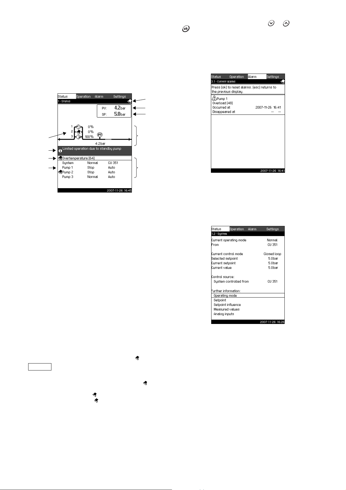
Fig. 6 Status
Description
No settings can be made in this menu.
The current value (process value, PV) of the control parameter,
usually the discharge pressure, is shown in the upper right corner
(G) together with the selected setpoint (SP) (H).
The upper half of the display (A) shows a graphic illustration of
the pump system. The selected measuring parameters are shown
with sensor symbol and current value.
In the middle of the display, an information field (I) will be shown if
any of the following events occur
• limited operation due to standby pump
• proportional pressure influence active
• external setpoint influence active
• alternative setpoint active
• clock program active
• remote-controlled via Ethernet
• remote-controlled via GENI (RS-485).
The lower display half (B) shows
• the latest current alarm, if any, and the fault cause together
with the fault code in brackets
• system status with current operating mode and control source
• pump status with current operating mode and manual/auto.
If a fault has occurred, the symbol will be
shown in the alarm line (C) together with the
cause and fault code, for instance
Overtemperature (64).
If the fault is related to one of the pumps, the symbol will also
be shown in front of the status line (D) of the pump in question.
At the same time, the symbol will be flashing instead of the
pump symbol (E). The symbol will be shown to the right in the
top line of the display (F). As long as a fault is present, this
symbol will be shown in the top line of all displays.
To open a menu line, mark the line with or , and press
.
The display makes it possible to open status displays showing
• current alarms
• system status
• status of each pump.
11.4.1 Current alarms (3.1)
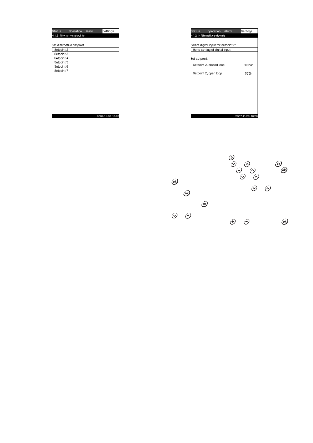
Fig. 7 Current alarms
Description
TM03 8947 4707
In this display, current unreset alarms and warnings are shown.
For further information, see sections 11.6.2 Current alarms (3.1)
and 11.6.3 Alarm log (3.2).
11.4.2 System (1.2)
Fig. 8 System
Description
This display shows the current operational state of the system. It
is possible to go to subdisplays showing details.
The display makes it possible to open specific displays about
• operating mode
•setpoint
• setpoint influence
• measured values
• analog inputs.
TM03 2293 4807TM03 8946 4807
15
Page 16

11.4.3 Operating mode (1.2.1)
Setpoint
current SP()
Setpoint
selected
Infl. 1() Infl. 2() ...×××=
11.4.4 Setpoint (1.2.2)
Fig. 9 Operating mode
Description
Here the operating mode of the system is shown as well as from
where the Control MPC is controlled.
Operating modes
Control MPC has six operating modes:
1. Normal
The pumps adapt their performance to the requirement.
2. Max.
The pumps run at a constant high speed. Normally, all pumps
run at maximum speed.
3. User-defined
The pumps run at a constant speed set by the user. Usually, it
is a performance between Max. and Min.
4. Min.
The pumps run at a constant low speed. Normally, one pump
is running at a speed of 70 %.
5. Stop
All pumps have been stopped.
6. Emergency run
The pumps run according to the setting made in the display
Emergency run (4.3.5).
The performance required in the operating modes Max., Min.,
User-defined and Emergency run can be set in the Settings
menu. See sections 11.7.33 Min., max. and user-defined duty
(4.3.14) and 11.7.25 Emergency run (4.3.5).
The current operating mode can be controlled from four different
sources: Fault, External signal, CU 351 and Bus.
Control source
Control MPC can be set to remote control via an external bus
(option). In this case, a setpoint and an operating mode must be
set via the bus.
In the Settings menu, it is possible to select whether the CU 351
or the external bus is to be the control source.
The status of this setting is shown in the display Operating
mode.
TM03 2273 4807
Fig. 10 Setpoint
Description
This display shows the selected setpoint and whether it comes
from the CU 351 or an external bus.
The display also shows all seven possible setpoints from CU 351
(for closed- and open-loop control). At the same time, the
selected setpoint is shown.
As it is a status display, no settings can be made.
Setpoints can be changed in the Operation or Settings menu.
See section 11.7.3 Alternative setpoints (4.1.2).
11.4.5 Setpoint influence (1.2.3)
Fig. 11 Setpoint influence
Description
The selected setpoint can be influenced by parameters. The
parameters are shown as percentage from 0 to 100 % or as a
pressure measured in bar, They can only reduce the setpoint, as
the influence in percentage divided with 100 is multiplied with the
selected setpoint:
TM03 2272 4807TM03 8948 4807
16
The display shows the parameters influencing the selected
setpoint and the percentage or value of influence.
Some of the possible parameters can be set in the display
External setpoint influence (4.1.3). The parameter low flow boost
is set as an on/off band as a percentage of the setpoint set in the
display Stop function (4.3.1). The parameter is set as a
percentage in the display Proportional pressure (4.1.7).
Finally the resulting current setpoint (SP) is shown.
Page 17

11.4.6 Measured values (1.2.4)
Note
11.4.8 Pump 1...6 (1.3 to 1.8)
Fig. 12 Measured values
Description
This display gives a general status of all measured and calculated
parameters.
The lines "Power consumption" and "Energy
consumption" are only shown in Control MPC-E
systems.
11.4.7 Analog inputs (1.2.5)
Fig. 13 Analog inputs
Description
The display shows an overview of the analog inputs and the
current measured values of each input. See sections
11.7.28 Analog inputs (4.3.8), 11.7.29 Analog inputs (4.3.8.1 to
4.3.8.7) and 1 1.7.30 Analog inputs and measured value (4.3.8.1.1
to 4.3.8.7.1).
TM03 2270 4807
Fig. 14 Pump 1
Description
This display shows the operational state of the individual pumps.
The pumps may have different operating modes:
• Au to
Together with the other pumps in automatic operation, the
pump is controlled by the PI controller which ensures that the
system delivers the required performance.
• Manual
The pump is not controlled by the PI controller. In manual
operation, the pump has one of the following operating modes:
– Max.
The pump runs at a set maximum speed. (This operating
mode can only be selected for variable-speed pumps.)
– Normal
The pump runs at a set speed.
– Min.
The pump runs at a set minimum speed. (This operating
mode can only be selected for variable-speed pumps.)
– Stop
The pump has been forced to stop.
Besides information about the operating mode, it is possible to
read various parameters in the status display, such as these:
• current operating mode
• control source
TM03 8949 4807
• speed (only 0 or 100 % are shown for mains-operated pumps)
• power (only Control MPC-E)
• energy consumption (only Control MPC-E)
• operating hours.
TM03 2268 4807
17
Page 18

11.5 Operation (2)
A
C
B
In this menu, the most basic parameters can be set, such as
setpoint, operating mode, control mode and forced control of
pumps.
11.5.1 Operation (2)
Fig. 15 Operation
Description
The column shows the setting range. In closed-loop control, it
corresponds to the range of the primary sensor, here 0-16 bar.
In open-loop control, the setting range is 0-100 %.
At the left hand of the column, the selected setpoint 1 (A) is
shown, i.e. the value set in the display. At the right hand of the
column, the current setpoint (B) is shown, i.e. the setpoint acting
as reference for the PI controller. If no kind of external setpoint
influence has been selected, the two values will be identical. The
current measured value (discharge pressure) is shown as the
grey part of the column (C). See sections 11.7.5 External setpoint
influence (4.1.3) and 11.7.6 Setting of influence function (4.1.3.2).
Below the display is a menu line for setting of setpoint 1 and
selection of operating mode, including the operating modes
Normal and Stop. It is possible to select further settings: system
operating mode, control mode, setpoints for closed and open loop
as well as individual pump control.
Setting range
Setpoint:
Closed-loop control: Measuring range of the primary sensor
Open-loop control: 0-100 %
Setting via control panel
Setpoint:
1. Mark the Operation menu with .
2. Mark Setpoint 1 with or . Set the value with or
.
3. Save with .
Operating mode:
1. Mark the Operation menu with .
2. Mark operating mode Normal or Stop with or .
Save with .
Further settings:
1. Mark the Operation menu with .
2. Mark Further settings with or , and press .
3. Select one of the settings below with or , and press
:
• System operating mode (see section 11.5.2).
• Control mode (see section 11.5.3).
• Setpoints (see section 11.5.4).
• Individual pump control (see section 11.5.6).
Factory setting
The setpoint is a value suitable for the system in question.
Thefactory setting may have been changed in the start-up menu.
11.5.2 System operating mode (2.1.1)
Fig. 16 System operating mode
Description
Control MPC can be set to six different operating modes. Normal
TM03 8950 4707
is the typical setting. See section 11.4.3 Operating mode (1.2.1).
The performance of the operating modes Max., Min., User-
defined and Emergency run can be set in the Settings menu.
In the display shown, it is possible to go directly to the Settings
menu in order to set the pump performance or the setpoint.
Setting range
It is possible to select the operating modes
Normal, Max., Min.,
User-defined, Stop and Emergency run.
Setting via control panel
1. Mark the Operation menu with .
2. Mark Further settings with or , and press .
3. Mark System operating mode with or , and press
.
4. Select the desired operating mode by marking one of the lines
with check boxes with or , and press .
5. In order to set the performance in min., max., user-defined
duty or emergency run, mark the desired line at the bottom of
the display, and press .
See sections 11.7.33 Min., max. and user-defined duty
(4.3.14) and 11.7.25 Emergency run (4.3.5).
Factory setting
Normal.
TM03 8951 4607
18
Page 19

11.5.3 Control mode (2.1.2)
P [bar]
Time [sec]
Setpoint
Input [%] from
external controller
Flow rate [m
3
/h]
10050 70.75
25
50
75
100
86.6
Flow rate [m3/h]
Input [%] from
external controller
Pump 1
Pump 4
Pump 3
Flow rate
Pump 2
Fig. 17 Control mode
Description
There are two control modes, namely closed and open loop.
Examples:
Closed loop
The typical control mode is closed loop where the built-in
PI controller ensures that the system reaches and maintains the
selected setpoint. The performance is based on the setpoint set
for closed loop. See figs 18 and 19.
Open loop
In open-loop control, the pumps run at a fixed speed.
The pump speed is calculated from the performance set by the
user (0-100 %). The pump performance in percentage is
proportional with the flow rate.
Open-loop control is usually used when the system is controlled
by an external controller which controls the performance via an
external signal. The external controller could for instance be a
building management system connected to the Control MPC.
In such cases the Control MPC is like an actuator.
See figs 20 and 21.
TM03 2283 4807TM03 2231 3905TM03 2390 4105
TM03 2232 3905
Fig. 20 Booster system with external controller (open loop)
Setting via control panel
1. Mark the Operation menu with .
2. Mark Further settings with or , and press .
3. Mark Control mode with or , and press .
4. Select Closed loop with or , and press .
5. Set the setpoint. See sections 11.5.4 Setpoints (2.1.3) and
Fig. 18 Booster system controlled by built-in PI controller
(closed loop)
Fig. 19 Regulation curve for closed loop
11.5.1 Operation (2).
0
5
Fig. 21 Regulation curve for open loop
Fig. 22 Regulation curve for Control MPC-E in open loop
TM03 2391 3607TM03 9977 4807
19
Page 20

Fig. 23 Regulation curve for Control MPC-F in open loop
10050 70.75
25
50
75
100
86.6
Input [%] from
external controller
Flow rate [m3/h]
Pump 1
Pump 2
Pump 3
Flow rate
Pump 4
10050 70.75
25
50
75
100
86.6
Flow rate [m3/h]
Input [%] from
external controller
Pump 1
Pump 4
Pump 3
Flow rate
Pump 2
Fig. 24 Regulation curve for Control MPC-S in open loop
Setting range
These settings must be made in connection with open loop:
• Stop of system.
• Selection of control mode Open loop.
• Setting of setpoint 1, open loop.
• Setting of external setpoint influence.
• Selection of operating mode Normal.
Setting via control panel
To set an external control source to control the system, proceed
as follows:
1. Mark the Operation menu with .
2. Mark the operating mode Stop with or , and press
. The check mark in the right box shows that the
operation has been stopped.
3. Mark Further settings with or , and press .
4. Mark Control mode with or , and press .
5. Select Open loop with or , and press .
6. Return by pressing twice.
7. Mark Set setpoint 1, open loop with or .
8. Set the setpoint to 100 % with , and save with .
9. Mark the Settings menu with .
10.Mark Primary controller with or , and press .
11. Mark External setpoint influence with or , and press
TM03 9975 4807TM03 9974 4807
.
12.Mark Go to setting of analog input with or , and
press .
13.Select the analog input with or , and press .
14.Select the range of the analog input with or , and
press . The selection is indicated by a check mark.
15.Mark Measured input value with or , and press .
Now the display 4.3.8.1.1 appears.
16.Select 0-100 % signal with or , and press .
17.Press to return to display 4.3.8.1.
18.Set the minimum sensor value with or , and save with
.
19.Set the maximum sensor value with or , and save
with .
20.Return by pressing twice.
21.Mark Input value to be influenced by with or , and
press .
22.Mark the 0-100 % signal with or , and press .
23. Return with .
24.Mark Set the influence function with or , and press
. For details, see section 11.7.6 Setting of influence
function (4.1.3.2).
25.Mark the menu line for number of points with or , and
press .
26.Select the required number of points with or , and
save with .
27.Mark External input value (point 1) with or .
28.Set the value of the external input value with or , and
save with .
29.Mark Reduce setpoint to (point 1) with or .
30.Set the value as a percentage with or , and save with
.
31.Repeat steps 27 to 31 for all chosen points.
32. Return with .
33.Mark Filter time with or , set the time in seconds with
or , and save with .
34.Mark Activated with or , and press . The check
mark in the right box shows that the function has been
activated.
35.Return by pressing twice.
36.Mark the Operation menu with .
37.Mark the operating mode Normal
with or , and press
. The check mark in the right box shows that the
operation is normal. The booster system can now be
controlled by an external controller.
Factory setting
Closed-loop control.
20
Page 21

11.5.4 Setpoints (2.1.3)
11.5.5 Individual pump control (2.1.4)
Fig. 25 Setpoints
Description
In addition to the primary setpoint 1 (shown in the display 2 in the
Operation menu), six alternative setpoints can be set for closedloop control. It is furthermore possible to set seven setpoints for
open-loop control.
As described in sections 11.7.3 Alternative setpoints (4.1.2) and
11.7.4 Alternative setpoints 2 to 7 (4.1.2.1 to 4.1.2.7), it is
possible to activate one of the alternative setpoints by means of
external contacts.
Setting range
The setting range of setpoints for closed-loop control depends on
the range of the primary sensor. See section 11.7.7 Primary
sensor (4.1.4).
In open loop control, the setting range is 0-100 %.
Setting via control panel
1. Mark the Operation menu with .
2. Mark Further settings with or , and press .
3. Mark Setpoints with or , and press .
4. Select the setpoint with or .
5. Set the setpoint with or , and press .
Factory setting
Setpoint 1 for closed-loop control is a value suitable for the
Control MPC in question.
The alternative setpoints for closed-loop control are 3 bar.
All setpoints for open-loop control are 70 %.
TM03 8952 4807
Fig. 26 Individual pump control
Description
It is possible to change the operating mode from automatic
operation to one of the manual operating modes.
Auto
The pumps are controlled by the PI controller, ensuring that the
system delivers the required performance.
Manual
The pump is not controlled by the PI controller, but set to one of
the following manual operating modes:
• Ma x.
The pump runs at a set maximum speed. (This operating
mode can only be selected for variable-speed pumps.)
• Normal
The pump runs at a set speed.
• Mi n.
The pump runs at a set minimum speed. (This operating mode
can only be selected for variable-speed pumps.)
• Stop
The pump has been forced to stop.
Pumps in manual operation are not part of the normal pump
cascade and speed control. The manual pumps are a
"disturbance" of the normal operation of Control MPC.
If one or more pumps are in manual operation, the system may
not be able to deliver the set performance.
There are two displays for the function. In the first display, the
pump to be set is selected, and in the next display, the operating
mode is selected.
Setting range
All pumps can be selected.
Setting via control panel
1. Mark the Operation menu with .
2. Mark Further settings with or , and press .
3. Mark Individual pump control with or , and press
.
4. Select the pump with or , and press .
TM03 8953 4807
21
Page 22

11.5.6 Setting of individual operating mode (2.1.4.1 to 2.1.4.6)
Fig. 27 Setting of individual operating mode
Description
This display is shown for the individual pumps and makes it
possible to set an operating mode.
Setting range
It is possible to select Auto or Manual as well as the operating
mode of the pump for manual operation - Max., Normal, Min. or
Stop. For mains-operated pumps only Normal or Stop can be
selected.
Setting via control panel
1. Mark the Operation menu with .
2. Mark Individual pump control with or , and press
.
3. Select the pump with or , and press .
4. Mark Auto or Manual with or , and press .
5. Manual: Select the operating mode with or , and
press .
6. Normal: Mark Setpoint with or .
Set the speed of the variable-speed pump with or ,
and press .
Factory setting
Auto.
TM03 8954 4807
22
Page 23

11.6 Alarm (3)
The Alarm menu gives an overview of alarms and warnings.
In this menu, it is possible to reset alarms and to see the alarm
log.
11.6.1 Alarm status (3)
Fault
Warning( ) / alarm( )
Change of operating
mode to
Reset of alarm
Restart
Set in the Settings
menu
Water shortage Man/auto X 206
Water shortage Stop Man/auto X 214
Pressure high Stop Man/auto X 210
Alarm code
Fig. 28 Alarm status
Description
A fault in the system or one of the components monitored can
cause an alarm or a warning . Besides the fault signal via
the alarm/warning signal relay and the red indicator light on the
CU 351, an alarm can also cause a change of operating mode,
for instance from Normal to Stop. A warning only causes a fault
indication.
The table shows the possible causes of fault together with an
alarm code number, and whether they result in an alarm or a
warning. It also shows to what operating mode the system
changes in case of alarm, and whether restart of the system and
reset of the alarm is manual or automatic.
The table also shows that the reaction to some of the fault causes
mentioned can be set in the Settings menu. See sections
11.7.24Soft pressure build-up (4.3.3) and 11.7.41 Monitoring
functions (4.4) to 11.7.51 Pressure relief (4.4.8).
Pressure low
Pressure relief Auto X 219
Alarm, all pumps Stop Auto 203
TM03 2291 4607
External fault
Dissimilar sensor
signals
Fault, primary sensor Stop Auto 89
Fault, sensor Auto 88
Communication fault Auto 10
Phase failure Auto 2
Undervoltage, pump Auto
Overvoltage, pump Auto 32
Overload, pump Auto
Motor temperature too
high
Other fault, pump Auto 76, 83
Internal fault, CU 351 Auto
Internal fault, IO 351 Stop Auto
VFD not ready Auto 213
Fault, Ethernet Auto
Limit 1 exceeded Man/auto X 190
Man/auto
Stop Man/auto
Man/auto
Stop Man/auto
Auto 204
Auto
X211
X3
7, 40,
42, 73
48, 50,
51, 54
64, 65,
67, 70
83,
157
72, 83,
157
231,
232
Limit 2 exceeded Man/auto X 191
Pressure build-up fault Man/auto X 215
Pumps outside duty
range
Pilot pump fault Auto 216
Man/auto X 208
23
Page 24

11.6.2 Current alarms (3.1)
Fig. 29 Current alarms
Description
This submenu shows the following:
• Warnings caused by faults that still exist.
• Warnings caused by faults that have disappeared, but the
warning requires manual reset.
• Alarms caused by faults that still exist.
• Alarms caused by faults that have disappeared, but the
alarm requires manual reset.
All warnings and alarms with automatic reset are automatically
removed from the menu when the fault has disappeared.
Alarms requiring manual reset are reset in this display by
pressing . An alarm cannot be reset until the fault has
disappeared.
For every warning or alarm, the following will be shown:
• Whether it is a warning or an alarm .
• Where the fault occurred: System, Pump 1, Pump 2, etc.
• In case of input-related faults, the input will be shown.
• What the cause of the fault is, and the alarm code in brackets:
Water shortage (214), Max. pressure (210), etc.
• When the fault occurred: Date and time.
• When the fault disappeared: Date and time. If the fault still
exists, date and time are shown as --...--.
The latest warning/alarm is shown at the top of the display.
11.6.3 Alarm log (3.2)
The alarm log can store up to 24 warnings and alarms.
TM03 2293 4607
TM03 2292 4807
Fig. 30 Alarm log
Description
Here warnings and alarms are shown.
For every warning or alarm, the following will be shown:
• Whether it is a warning or an alarm .
• Where the fault occurred. System, Pump 1, Pump 2, etc.
• In case of input-related faults, the input will be shown.
• What the cause of the fault is, and the alarm code in brackets:
Water shortage (214), Max. pressure (210), etc.
• When the fault occurred: Date and time.
• When the fault disappeared: Date and time. If the fault still
exists, date and time are shown as --...--.
The latest warning/alarm is shown at the top of the display.
24
Page 25

11.7 Settings (4)
11.7.1 Primary controller (4.1)
Fig. 31 Settings
In the Settings menu, it is possible to set the following functions:
• Primary controller
Setting of PI controller, alternative setpoints, external setpoint
influence, primary sensor, clock program, proportional pressure
and S-system configuration.
• Pump cascade control
Setting of min. time between start/stop, max. number of starts/
hour, number of standby pumps, forced pump changeover,
pump test run, pilot pump, pump stop attempt, pump start and
stop speed, min. performance and compensation for pump
start-up time.
• Secondary functions
Setting of stop function, soft pressure build-up, digital and
analog inputs, digital outputs, emergency run, min., max. and
user-defined duty, pump curve data, flow estimation, control
source and fixed inlet pressure.
• Monitoring functions
Setting of dry-running protection, min. and max. pressure,
external fault, limit 1 and 2 exceeded, pumps outside duty
range and pressure relief.
• Functions, CU 351
Selection of service language, main language and units.
Setting of time and date, passwords, Ethernet connection,
GENIbus number and software status.
Usually, all these functions are set correctly when the
Control MPC is switched on.
It is only necessary to make settings in this menu if the
functionality is to be expanded with for instance alternative
setpoints or setpoint influence, or if the settings of the CU 351 are
to be adjusted.
TM03 2294 4607
Fig. 32 Primary controller
Description
In this menu section, it is possible to set the functions related to
the primary controller.
It is only necessary to make settings in this menu if the
functionality is to be expanded with for instance alternative
setpoints, external setpoint influence, clock program or
proportional pressure.
The following menus can be selected:
• PI controller
• Alternative setpoints
• External setpoint influence
• Primary sensor
• Clock program
• Proportional pressure
• S-system configuration.
TM03 8955 4807
25
Page 26

11.7.2 PI controller (4.1.1)
ǻS
L [m]
ǻS
1
Q
t
L [m]
2
ǻW
L [m]
2
t
L [m]
2
PI controller settings for heating and cooling
If another application than pressure boosting has been selected
in the start-up wizard, the values of K
and Ti will be set
p
automatically according to the table below. As Control MPC does
not know the pipe length, the default parameters will be set
according to the table to a pipe length (L
System/application
Heating
system
1)
or L2) of 5 metres.
1
K
p
Cooling
system
2)
T
i
[Seconds]
0.5 1
Fig. 33 PI controller
Description
Control MPC includes a standard PI controller which ensures that
the pressure is stable and corresponds to the setpoint.
It is possible to adjust the PI controller if a faster or slower
reaction to changes of consumption is required.
A faster reaction is obtained if K
A slower reaction is obtained if K
is increased and Ti is reduced.
p
is reduced and Ti is increased.
p
Setting range
• Gain K
• Integral time T
: –30 to 30.
p
Note: For inverse control, set K
: 0.1 to 3600 seconds.
i
to a negative value.
p
Setting via control panel
1. Mark the Settings menu with .
2. Mark Primary controller with or , and press .
3. Mark PI controller with or , and press .
4. Select the gain (K
) with or . Set the value with
p
or , and save with .
Note: Usually it is not necessary to adjust K
5. Select the integral time (T
) with or . Set the time with
i
.
p
or , and press .
Factory setting
The setting of K
and Ti depends on the system and application.
p
PI controller settings for pressure boosting
If the application has been set to pressure boosting in the start-up
wizard, the following values of K
: 0.5
•K
p
: 1 second.
•T
i
and Ti will be set automatically:
p
TM03 2387 4607
1)
Heating systems are systems in which an increase in pump
performance will result in a temperature rise at the sensor.
2)
Cooling systems are systems in which an increase in pump
performance will result in a temperature drop at the sensor.
: Distance [m] between pump and sensor.
L
1
: Distance [m] between heat exchanger and sensor.
L
2
ΔP: Measurement of differential pressure.
Q: Measurement of flow rate.
t: Measurement of temperature.
t: Measurement of differential temperature.
Δ
L
< 5 m: 1
0.5
1
L
> 5 m: 3
1
L
> 10 m: 5
1
0.5 1
0.5 -0.5 10 + 5L
0.5 10 + 5L
0.5 -0.5 30 + 5L
2
2
2
26
Page 27
11.7.3 Alternative setpoints (4.1.2)
11.7.4 Alternative setpoints 2 to 7 (4.1.2.1 to 4.1.2.7)
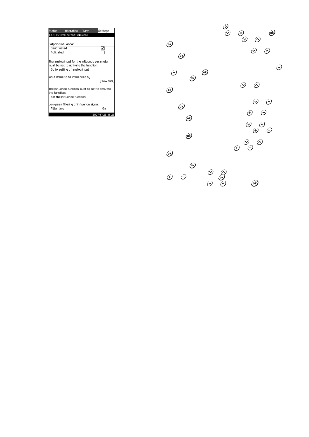
Fig. 34 Alternative setpoints
Description
This function makes it possible to select up to six setpoints (No 2
to 7) as alternatives to the primary setpoint (No 1). The primary
setpoint (No 1) is set in the Operation menu.
Every alternative setpoint can be addressed manually to a
separate digital input (DI). When the contact of the input is
closed, the alternative setpoint applies.
If more than one alternative setpoint has been selected and they
are activated at the same time, the CU 351 selects the setpoint
with the lowest number.
Setting range
• Six setpoints, No 2 to 7.
Factory setting
No alternative setpoints have been selected.
TM03 2383 4607
Fig. 35 Alternative setpoints 2 to 7
For each alternative setpoint, select the digital input to activate
the setpoint.
It is possible to set a setpoint for closed loop and for open loop.
Setting via control panel
1. Mark the Settings menu with .
2. Mark Primary controller with or , and press .
3. Mark Alternative setpoints with or , and press .
4. Select the alternative setpoint with or , and press
.
5. Mark Go to setting of digital input with or , and
press .
Now the display Digital inputs (4.3.7) appears. Set the input
and return with .
6. Mark the menu line of the setpoint (closed or open loop) with
or .
7. Set the required setpoint with or , and save with .
Set both setpoints if the system is to be controlled both in
open and closed loop.
Factory setting
No alternative setpoints have been set.
TM03 2384 4607
27
Page 28
11.7.5 External setpoint influence (4.1.3)
Setpoint
current SP()
Setpoint
selected
Infl. 1() Infl. 2() ...×××=
Fig. 36 External setpoint influence
Description
This function makes it possible to adapt the setpoint by letting
measuring parameters influence the setpoint. Typically an analog
signal from a flow or temperature transmitter, or a similar
transmitter. Section 12. Measuring parameters shows an
overview of transmitter types and possible positions.
As an example, the setpoint can be adapted to parameters that
can influence the discharge pressure or temperature of the
system. The parameters which influence the performance of the
system are shown as a percentage from 0 to 100 %. They can
only reduce the setpoint, as the influence as a percentage divided
with 100 is multiplied with the setpoint:
The influence values can be set individually.
A low-pass filter ensures smoothing of the measured value which
influences the setpoint. This results in stable setpoint changes.
Setting range
The following parameters can be selected.
• 0-100 % signal
• Inlet pressure
• Discharge pressure
• External pressure
• Differential pressure, pump
• Differential pressure, external
•Flow rate
• Tank level, discharge side
• Tank level, suction side
• Flow pipe temperature
• Return pipe temperature
• Ambient temperature
• Return pipe temperature, external
• Differential temperature.
Setting via control panel
1. Mark the Settings menu with .
2. Mark Primary controller with or , and press .
3. Mark External setpoint influence with or , and press
.
4. Mark Input value to be influenced by with or , and
press .
Now a list of available parameters appear.
5. Mark the parameter which is to influence the setpoint with
or , and press .
6. Return with .
7. Mark Set the influence function with or , and press
. For details, see section 11.7.6 Setting of influence
function (4.1.3.2).
8. Mark the menu line for number of points with or , and
press .
9. Select the required number of points with or , and
TM03 8956 4807
save with .
10.Mark External input value (point 1) with or .
11.Set the value of the external input value with or , and
save with .
12.Mark Reduce setpoint to (point 1) with or .
13.Set the value as a percentage with or , and save with
.
14.Repeat steps 8 to 13 for all desired parameters.
15. Return with .
16.Mark Filter time with or , set the time in seconds with
or , and save with .
17.Mark Activated with or , and press . The check
mark in the right box shows that the function has been
activated.
Factory setting
Setpoint influence is not activated.
28
Page 29

11.7.6 Setting of influence function (4.1.3.2)
0
140
10
100
100
25
Temperature [°C]
Setpoint influence [%]
Fig. 37 Setting of influence function
Description
In this menu, you select the relation between the measuring
parameter which is to influence the setpoint and the desired
influence as a percentage.
The relation is set by entering values in a table with maximum
eight points by means of the control panel.
Example:
Setting via control panel
1. Mark the Settings menu with .
2. Mark Primary controller with or , and press .
3. Mark External setpoint influence with or , and press
.
4. Mark Set the influence function with or , and press
.
5. Mark the menu line for number of points with or , and
press .
6. Select the required number of points with or , and
save with .
7. Mark External input value (point 1) with or .
8. Set the value of the external input value with or , and
save with .
9. Mark Reduce setpoint to (point 1) with or .
10. Set the value as a percentage with or , and save with
TM03 9963 4707TM03 9978 4707
.
11. Repeat steps 7 to 10 for all desired parameters.
Factory setting
External setpoint influence is not activated.
11.7.7 Primary sensor (4.1.4)
Fig. 38 Relation between setpoint influence and flow rate
The control unit draws straight lines between the points. A
horizontal line is drawn from the minimum value of the relevant
sensor (0 m
case from the last point to the sensor's maximum value (example
3
50 m
/h).
Setting range
Two to eight points can be selected. Each point contains the
relation between the value of the parameter which is to influence
the setpoint and the influence of the value.
3
/h in the example) to the first point. This is also the
TM03 8958 4807
Fig. 39 Primary sensor
Description
In this display, select the control parameter of the system and set
the sensor to measure the value.
For booster systems, the control parameter is usually the
discharge pressure which is measured by a sensor fitted on the
discharge manifold. In heating and cooling systems, the control
parameter is typically a differential pressure or a temperature.
See section 12. Measuring parameters.
Setting range
• Discharge pressure
• Differential pressure, external
• Differential pressure, pump
• Series 2000, differential pressure
• External pressure
• Differential pressure, inlet
• Differential pressure, outlet
•Flow rate
• Series 2000, flow rate
• Flow pipe temperature
• Return pipe temperature
• Differential temperature
• Ambient temperature
• Return pipe temperature, external
• 0-100 % signal
• Not used.
29
Page 30

Setting via control panel
Note
1. Mark the Settings menu with .
2. Mark Primary controller with or , and press .
3. Mark Primary sensor with or , and press .
4. Mark Go to setting of analog input with or , and
press .
Now the display Analog inputs (4.3.8) appears. Select the
analog input (AI) for the primary sensor, and set the
parameters for this sensor. Return to display Primary sensor
(4.1.4) with .
5. Select the control parameter for the primary sensor with
or , and press .
Factory setting
The primary parameter is discharge pressure. The sensor is
connected to AI1 (CU 351). Other primary parameters can be
selected in the start-up wizard.
11.7.8 Clock program (4.1.6)
Setting range
• Activation of the function.
• Activation and setting of event.
Setting via control panel
1. Mark the Settings menu with .
2. Mark Primary controller with or , and press .
3. Mark Clock program with or , and press .
4. Mark Event 1 with or , and press .
TM03 8959 4807
Fig. 41 Event 1
Fig. 40 Clock program
Description
With this function, it is possible to set setpoints and day and time
for their activation. It is also possible to set day and time for stop
of the system.
If the clock program is deactivated, the setpoint of the program
will remain active.
Minimum 2 events are required when activating
the clock program; one to start the system and
one to stop the system.
5. Mark operating mode Normal or Stop with or , and
press . (If Stop is selected, step 6 will be skipped.)
6. Mark Setpoint, closed loop with or .
Set the pressure with or , and save with .
7. Mark Time (hours, minutes) with or .
8. Set the time with or , and save with .
TM03 8990 4807
9. Mark day of week on which the settings are to be activated
with or , and press .
10.Mark Activated with or , and press .
11.Repeat steps 4 to 10 if several events are to be activated.
Note: Up to ten events can be set.
12. Return with .
13.Mark Activated with or , and press . The check
mark in the right box shows that the function has been
activated.
Factory setting
The function is deactivated.
30
Page 31

11.7.9 Proportional pressure (4.1.7)
Setpoint
Resultant setpoint, linear
Pump curve
Starting point of proportional pressure control
(Influence at 0 flow = x % of H
set
)
Resultant setpoint, square
H
set
Start/stop band
H
set
Time [sec]
H [m]
Pump stops
Pump starts
Normal control
Start/stop band
H
set
Time [sec]
H [m]
Pump starts
Pump stops
Inverse control
11.7.10 S-system configuration (4.1.8)
Description
The function can only be activated in pressure-controlled systems
and automatically adapts the setpoint set to the current flow rate.
The adaptation can be linear or square. See fig. 43.
The function has these purposes:
• to compensate for pressure losses
• to reduce the energy consumption
• to increase the comfort for the user.
Setting range
• Activation of the function.
• Selection of control mode.
• Setting of setpoint influence.
Setting via control panel
1. Mark the Settings menu with .
2. Mark Primary controller with or , and press .
3. Mark Proportional pressure with or , and press
4. Mark Activated with or , and press . The check
5. Mark Adaptation, linear or square with or , and
6. Mark Influence at 0 flow with or . Set the value with
Factory setting
The function is deactivated.
Fig. 42 Proportional pressure
Fig. 43 Proportional pressure
.
mark in the right box shows that the function has been
activated.
press .
or , and save with .
TM03 8960 4807TM03 8524 1807
Fig. 44 S-system configuration
Description
The function makes it possible to invert the control of mainsoperated pumps (Control MPC-S). That is to set whether pumps
are to be started or stopped depending on the current value.
A start/stop band must be set in order to use this function.
See fig. 45.
Normal control: A pump is stopped when the current value
becomes higher than H
+ start/stop band. And a pump is
set
started when the current value becomes lower than H
See fig. 45.
Inverse control: A pump is started when the current value
becomes higher than H
+ start/stop band. And a pump is
set
stopped when the current value becomes lower than H
See fig. 45.
Fig. 45 Normal and inverse control
Setting range
• Selection of configuration (normal or inverse control).
• Setting of start/stop band.
Setting via control panel
1. Mark the Settings menu with .
2. Mark Primary controller with or , and press .
3. Mark S-system configuration with or , and press
.
4. Mark Inverse with or , and press .
5. Mark Start/stop band with or . Set the value
with or , and save with .
Factory setting
Normal.
set
set
TM03 8961 4807TM03 9205 3607 - TM03 9205 3607
.
.
31
Page 32

11.7.11 Pump cascade control (4.2)
Note
Fig. 46 Pump cascade control
Factory setting
The setting is done in the start-up wizard and depends on the
application.
11.7.13 Max. number of starts/hour (4.2.1)
TM03 8962 4807TM03 2367 4607
In this menu section, it is possible to set the functions connected
to pump cascade control.
The following menus can be selected:
• Min. time between start/stop
• Max. number of starts/hour
• Standby pumps
• Forced pump changeover
• Pump test run
• Pilot pump
• Pump stop attempt
• Pump start and stop speed
• Min. performance
• Compensation for pump start-up time.
11.7.12 Min. time between start/stop (4.2.1)
TM03 2367 4607
Fig. 48 Max. number of starts/hour
Description
This function limits the number of pump starts and stops per hour
for the complete system. It reduces noise emission and improves
the comfort of systems with mains-operated pumps.
Each time a pump starts or stops, the CU 351 calculates when
the next pump is allowed to start/stop in order not to exceed the
permissible number of starts per hour.
The function always allows pumps to be started to meet the
requirement, but pump stops will be delayed, if needed, in order
not to exceed the permissible number of starts per hour.
The time between pump starts must be between the minimum
time between start/stop, see section 11.7.12, and 3600/n, n being
the set number of starts per hour.
Setting range
1 to 1000 starts per hour.
Setting via control panel
1. Mark the Settings menu with .
2. Mark Pump cascade control with or , and press
.
3. Mark Max. number of start s/hour with or , and press
.
4. Set the permissible number of starts per hour with or
, and save with .
Factory setting
Control MPC-E: 200 starts per hour
Other variants: 100 starts per hour
Fig. 47 Min. time between start/stop
Description
This function ensures a delay between the starting/stopping of
one pump and the starting/stopping of another pump.
The purpose is to prevent hunting when pumps start and stop
continuously.
Setting range
From 1 to 3600 seconds.
Setting via control panel
1. Mark the Settings menu with .
2. Mark Pump cascade control with or , and press
.
3. Mark Min. time between start/stop with or , and
press .
4. Set the required minimum time with or , and save
with .
32
This function has no influence on Stop function
(4.3.1).
Page 33

11.7.14 Standby pumps (4.2.3)
11.7.15 Forced pump changeover (4.2.4)
Fig. 49 Standby pumps
Description
This function makes it possible to limit the maximum performance
of the system, by selecting one or more pumps as standby
pumps.
If a three-pump system has one standby pump, maximum two
pumps are allowed to be in operation at a time.
If one of the two pumps in operation has a fault and is stopped,
the standby pump will be started. The performance of the system
is thus not reduced.
The status as standby pump alternates between all pumps.
Setting range
The number of possible standby pumps in a system is equal to
the total number of pumps in the system minus 1.
Setting via control panel
1. Mark the Settings menu with .
2. Mark Pump cascade control with or , and press
.
3. Mark Standby pumps with or , and press .
4. Select the number of standby pumps with or , and
save with .
Factory setting
The number of standby pumps is set to 0, i.e. function is
deactivated.
TM03 2366 4607
Fig. 50 Forced pump changeover
Description
This function ensures that the pumps run for the same number of
operating hours.
In certain applications, the requirement remains constant for long
periods and does not require all pumps to run. In such situations,
pump changeover does not take place naturally, and forced pump
changeover may thus be required.
Once every 24 hours, the CU 351 checks if any pump running has
a larger number of operating hours than pumps that are stopped.
If this is the case, the pump will be stopped and replaced by a
pump with a lower number of operating hours.
Setting range
The function can be activated/deactivated. The hour of the day at
which the changeover is to take place can be set.
Setting via control panel
1. Mark the Settings menu with .
2. Mark Pump cascade control with or , and press
.
3. Mark Forced pump changeover with or , and press
.
4. Mark Activated with or , and press . The check
mark in the right box shows that the function has been
activated.
5. Mark Time for changeover with , and press .
6. Set the time with or , and save with .
Factory setting
The function is activated. The time is set to 03:00.
TM03 2365 1109
33
Page 34

11.7.16 Pump test run (4.2.5)
Note
Note
11.7.17 Pilot pump (4.2.6)
Fig. 51 Pump test run
Description
This function is primarily used in situations where the forced
pump changeover is deactivated, and/or if the Control MPC is set
to operating mode Stop, for instance in a period when the system
is not needed.
In such situations, it is important to test the pumps regularly.
The function ensures that
• pumps do not seize up during a long standstill due to deposits
from the pumped liquid.
• the pumped liquid does not decay in the pump.
• trapped air is removed from the pump.
The pumps start automatically one by one and run for five
seconds.
Pumps in the operating mode Manual are not
included in the test run. If there is an alarm, the
test run will not be carried out.
Pilot pumps are included in the pump test run.
Setting range
• Not used.
• Once every 24 hours.
• Once every 48 hours.
• Once a week.
Setting via control panel
1. Mark the Settings menu with .
2. Mark Pump cascade control with or , and press
.
3. Mark Pump test run with or , and press .
4. Select the interval with or .
5. Activate the function with .
Factory setting
The setting is done in the start-up wizard and depends on the
application.
TM03 2364 4607
Fig. 52 Pilot pump
Description
The function controls a pilot pump via a digital output. The pilot
pump takes over the operation from the main pumps in periods
when the consumption is so small that the stop function of the
main pumps is activated. See section 11.7.23 Stop function
(4.3.1).
Via a digital input, the operational state of the pilot pump is
monitored, i.e. whether it is operational or in a fault condition.
The purpose is to
• save energy
• reduce the number of operating hours of the main pumps.
If the pilot pump cannot keep the pressure by itself, one or more
main pumps are started. If only one main pump is started and
runs on/off operation, the pilot pump remains cut in. If one or
more main pumps run continuously, the pilot pump is cut out.
Set the setpoint of the pilot pump to this value:
H
+ 1/2 on/off band + 8 metres.
set
If the setpoint of the main pumps is changed, the
setpoint of the pilot pump must be changed too.
Setting range
• See section 11.7.31 Digital outputs (4.3.9).
• See section 11.7.26 Digital inputs (4.3.7).
Setting via control panel
1. Mark the Settings menu with .
2. Mark Pump cascade control with or , and press
.
3. Mark Pilot pump with or , and press .
4. Mark Go to setting of digital output with or , and
press .
5. Select a digital output with or , and press .
6. Mark Pilot pump control with or , and save with
.
7. Return by pressing twice.
8. Mark Go to setting of digital input with or , and
press .
9. Select a digital input or , and press .
10.Mark Pilot pump fault with or , and save with .
Factory setting
The function is deactivated.
TM03 8963 4807
34
Page 35
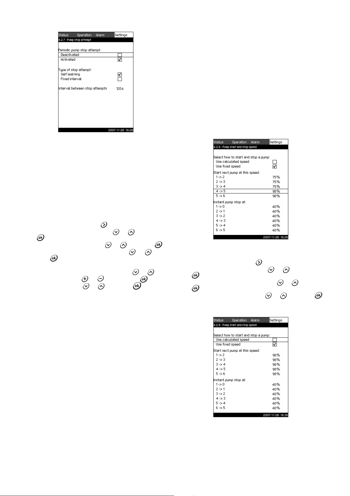
11.7.18 Pump stop attempt (4.2.7)
Fig. 53 Pump stop attempt
Description
The function makes it possible to set automatic stop attempts of a
pump when several pumps are running. It ensures that the
optimum number of pumps is always running, in terms of energy
consumption. See 11.7.19 Pump start and stop speed (4.2.8). At
the same time, the purpose is to avoid disturbances in connection
with automatic stop of pumps.
Stop attempts can either take place with a fixed interval set under
Interval between stop attempts or by self learning. If self
learning is selected, the interval between stop attempts will be
increased if repeated attempts to stop the pump fail.
Setting via control panel
1. Mark the Settings menu with .
2. Mark Pump cascade control with or , and press
.
3. Mark Pump stop attempt with or , and press .
4. Mark Self learning or Fixed interval with or , and
press .
5. If Fixed interval is selected:
6. Mark Interval between stop attempts with or .
7. Set the interval with or , and save with .
8. Mark Activated with or , and press . The check
mark in the right box shows that the function has been
activated.
Factory setting
The function is activated, and self learning is selected.
11.7.19 Pump start and stop speed (4.2.8) Description
The function controls the starting and stopping of pumps.
There are two options:
1. Use calculated speed
This function ensures that the optimum number of pumps is
always running at a desired duty point, in terms of energy
consumption. The CU 351 calculates the required number of
pumps and their speed. This requires that the differential
pressure of the pump is measured by a differential pressure
sensor or separate pressure sensors on the inlet and
discharge side.
When calculated speed has been selected, the CU 351
ignores the percentages set.
2. Use fixed speed
The pumps are started and stopped at speeds set by the user.
TM03 8964 4807
1. Use calculated speed
Fig. 54 Calculated pump start and stop speed
Setting via control panel
1. Mark the Settings menu with .
2. Mark Pump cascade control with or , and press
.
3. Mark Pump start and stop speed with or , and press
.
4. Mark Use calculated speed with or , and press .
2. Use fixed speed
TM03 8966 4807TM03 8965 4807
Fig. 55 Fixed pump start and stop speed
35
Page 36

Setting via control panel
1. Mark the Settings menu with .
2. Mark Pump cascade control with or , and press
.
3. Mark Pump start and stop speed with or , and press
.
4. Mark Use fixed speed with or , and press .
5. Mark Start of next pump at: 1->2 with or , and press
.
6. Set the speed as percentage with or , and save with
. Set the other pumps in the same way.
7. Mark Instant pump stop at: 1->0 with or , and press
.
8. Set the speed as percentage with or , and save with
. Set the other pumps in the same way.
Factory setting
The function is set to calculated speed.
11.7.20 Min. performance (4.2.9)
TM03 8967 4807
Fig. 56 Min. performance
11.7.21 Compensation for pump start-up time (4.2.10)
TM03 8968 4807
Fig. 57 Compensation for pump start-up time
Description
The function is used for Control MPC-F systems only.
The purpose is to avoid disturbances when a mains-operated
pump with fixed speed is started. The function compensates for
the time it takes a mains-operated pump to reach its full
performance after start. The start-up time of the mains-operated
pump must be known.
Setting via control panel
1. Mark the Settings menu with .
2. Mark Pump cascade control with or , and press
.
3. Mark Compensation for pump start-up time with or
, and press .
4. Set the start-up time with or , and save with .
Factory setting
The start-up time is set to 0 seconds.
Description
This function ensures circulation in a system. Note that the stop
function, if activated, can influence this function. See section
11.7.23 Stop function (4.3.1). Examples:
• If 0 pumps have been selected, the stop function can stop the
pump if there is no or a very small consumption.
• If pumps have been selected, the stop function is not active.
Setting via control panel
1. Mark the Settings menu with .
2. Mark Pump cascade control with or , and press
.
3. Mark Min. performance with or , and press .
4. Set Number of pumps with or , and save with .
5. Mark Speed with or . Set the speed with or ,
and save with .
Factory setting
The number of pumps is set to 0. The speed in closed loop is set
to 25 %.
36
Page 37
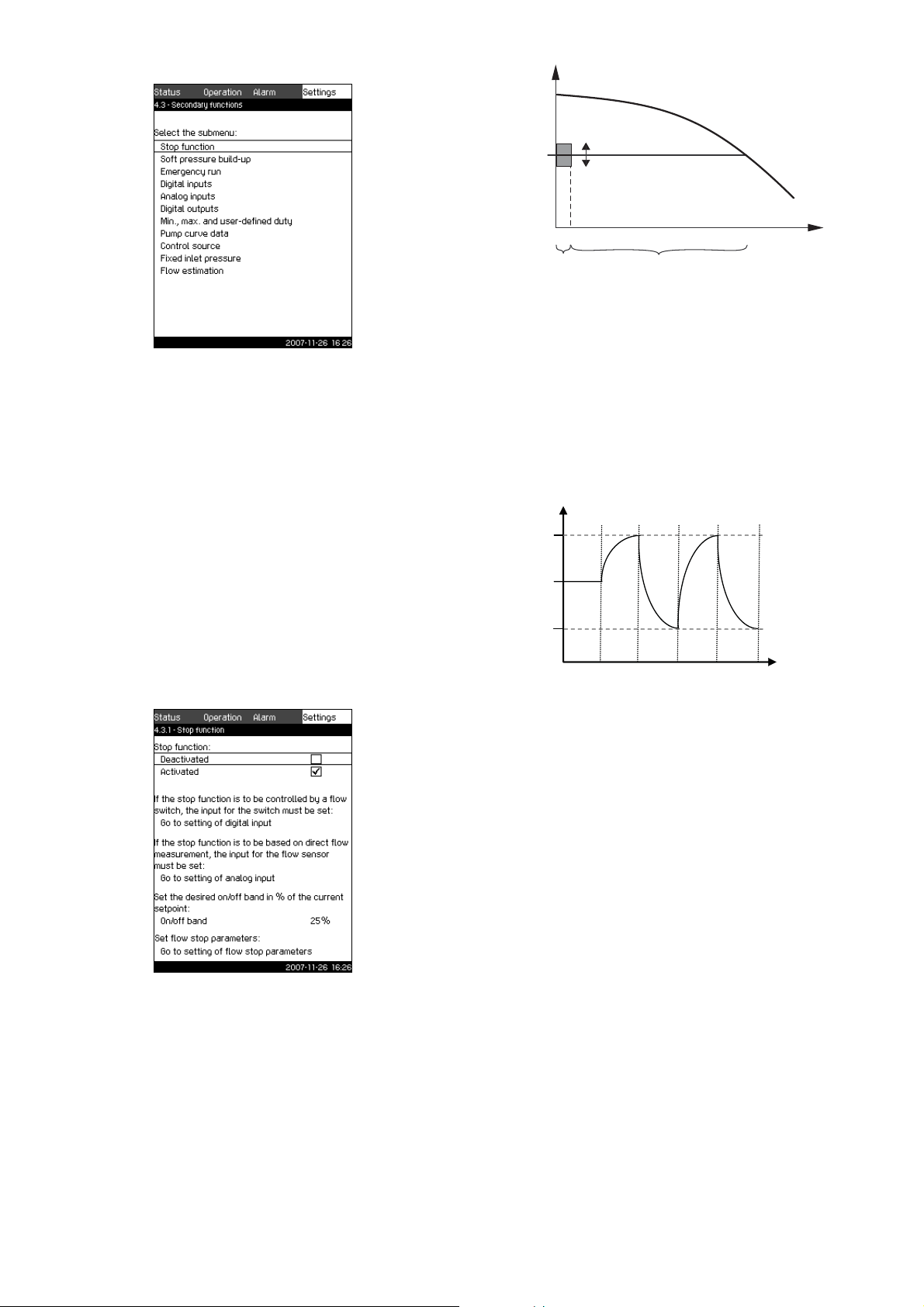
11.7.22 Secondary functions (4.3)
H
set
Q
min
On/off band
On/off
control
Normal operation
Stop = H
set
+ 0.5 x on/off band
Start = H
set
– 0.5 x on/off band
Stop
Star t
H [m]
Time [sec]
AB C B C
A: Normal operation
B: Pressure boosting
C: Stop
Fig. 58 Secondary functions
Description
Functions that are secondary in relation to the normal operation
of the system can be set in this display. Secondary functions are
functions that offer additional functionality.
The display makes it possible to open these specific displays:
• Stop function (4.3.1)
• Soft pressure build-up (4.3.3)
• Digital inputs (4.3.7)
• Analog inputs (4.3.8)
• D igital out puts (4.3 .9)
• Emergency run (4.3.5)
• Min., max. and user-defined duty (4.3.14)
• Pump curve data (4.3.19)
• Flow estimation (4.3.23)
• Control source (4.3.20)
• Fixed inlet pressure (4.3.22).
11.7.23 Stop function (4.3.1)
H
Fig. 60 On/off band
When the stop function is activated, the operation is continuously
TM03 8969 4807TM03 2355 4607
monitored to detect a low flow rate. When the CU 351 detects no
or a low flow rate (Q < Q
operation to on/off control of the last pump in operation.
Before stopping, the pump increases the pressure to a value
corresponding to H
set
when the pressure is H
), it changes from constant-pressure
min
+ 0.5 x on/off band. The pump is restarted
– 0.5 x on/off band. See fig. 61.
set
Q
TM03 1692 2705TM03 9292 4807
Fig. 59 Stop function
Description
This function is typically used in constant pressure applications
and makes it possible to stop the last pump if there is no or a very
small consumption. The purpose is to
• save energy
• prevent heating of shaft seal faces due to increased
mechanical friction as a result of reduced cooling by the
pumped liquid
• prevent heating of the pumped liquid.
The description of the stop function applies to all booster systems
with variable-speed pumps. Control MPC-S will have on/off
control of all pumps as described in section 8. Overview of control
variants.
Fig. 61 On/off operation
The flow rate is estimated by the CU 351 when the pump is in the
stop period. As long as the flow rate is lower than Q
will run on/off. If the flow rate is increased to above Q
pump returns to normal operation, H
set
. H
is equal to the
set
, the pump
min
, the
min
current setpoint. See section 11.4.4 Setpoint (1.2.2).
Detection of low flow rate
Low flow rate can be detected by means of
• direct flow measurement with a flowmeter or flow switch
• estimation of flow rate by measurement of pressure and
speed.
If the booster system is not connected to a flowmeter or flow
switch, the stop function will use the estimating function.
If the detection of low flow rate is based on flow estimation, a
diaphragm tank of a certain size and with a certain precharge
pressure is required.
37
Page 38

Diaphragm tank size
Note
Note
Pump type
Recommended diaphragm tank size [litres]
-E -F -S
CRI(E) 3 8 8 80
CRI(E) 5 12 12 120
CRI(E) 10 18 18 180
CRI(E) 15 80 80 300
CRI(E) 20 80 80 400
CR(E) 32 80 80 600
CR(E) 45 120 120 800
CR(E) 64 120 120 1000
CR(E) 90 180 180 1500
CR(E) 120 180 180 1500
CR(E) 150 180 180 1500
Precharge pressure
Hydro MPC-E and -F: 0.7 x setpoint.
Hydro MPC-S: 0.9 x setpoint.
During each flow estimation (every 2 minutes), the estimating
function will disturb the discharge pressure by ±10 % of the
setpoint. If this disturbance is not acceptable, the stop function
must be based on direct flow measurement with a flowmeter or
flow switch.
The minimum flow rate can be set, i.e. the flow rate at which the
booster system changes to on/off control of the last pump in
operation.
If both a flowmeter and a flow switch are connected, the
changeover to on/off control is determined by the unit first
indicating low flow rate.
Setting range
On/off band: 5 to 30 %
Min. flow rate: 2 to 50 % of the nominal flow rate (Q
nom
) of one
of the pumps. (Can only be set if direct flow
measurement by means of flowmeter has been
selected.)
Setting via control panel
System without flow switch or flowmeter
1. Mark the Settings menu with .
2. Mark Secondary functions with or , and press .
3. Mark Stop function with or , and press .
4. Mark Activated with or , and press .
The activation is indicated by a check mark in the box.
5. Mark On/off band with or .
6. Set the on/off band with or , and save with .
7. Mark Go to setting of flow stop parameters with or
, and press .
Now the display below is shown.
8. Select one of the stop parameters with or , and save
with . If Customised settings are selected, the
parameters shown in fig. 63 must be set. See examples
below.
Fig. 63 Customised settings
Rule of thumb: Speed reduction = 2 x delta
pressure for gradient.
Example 1: Increasing the stop limit, Q
(high flow limit)
min
• Increase the delta pressure for gradient.
• Reduce the delta time for gradient (pump stopped).
• Reduce the delta time for gradient (pump running).
• Increase speed reduction.
Example of increased stop limit
Parameter Value
Delta pressure for gradient 6 %
Delta time for gradient (pump stopped) 1.5 sec
Delta time for gradient (pump running) 2.0 sec
Speed reduction 10 %
Example 2: Reducing the stop limit, Q
(low flow limit)
min
• Reduce the delta pressure for gradient.
• Increase the delta time for gradient (pump stopped).
• Increase the delta time for gradient (pump running).
• Reduce speed reduction.
Example of reduced flow limit
Parameter Value
Delta pressure for gradient 3 %
Delta time for gradient (pump stopped) 15.0 sec
Delta time for gradient (pump running) 25.0 sec
Speed reduction 6 %
TM03 8957 4807
The stop limit depends on the tank size.
TM03 9966 4807
Fig. 62 Stop parameters
38
Page 39

Note
1. Filling phase
2. Pressure build-up phase
H [m]
Filling time Ramp time
Time [sec]
System with flow switch
Make the following additional settings:
1. Mark Go to setting of digital input with or , and
press . Now the display Digital inputs (4.3.7) appears.
2. Select the digital input where the flow switch is connected with
or , and press .
3. Mark Flow switch with or , press and return with
.
An open contact indicates low flow.
System with flowmeter
Make the following additional settings:
1. Mark Go to setting of analog input with or , and
press . Now the display Analog inputs (4.3.8) appears.
2. Select the analog input where the flowmeter is connected, and
set up the input for the flowmeter by selecting Flow rate.
3. Return to Stop function by pressing twice.
4. Mark Stop limit with or .
5. Set the value with or , and save with .
Factory setting
The function is activated in booster applications with the settings
in the table.
On/off band: 25 %
Min. flow rate: 30 % of the nominal flow rate of one pump
The function is deactivated in all other applications.
11.7.24 Soft pressure build-up (4.3.3)
Fig. 64 Soft pressure build-up
Description
This function is typically used in booster applications and ensures
a smooth start-up of systems with for instance empty pipes.
Start-up takes place in two phases. See fig. 65.
1. Filling phase.
The pipework is slowly filled with water. When the pressure
sensor of the system detects that the pipework has been filled,
phase two begins.
2. Pressure build-up phase.
The system pressure is increased until the setpoint is
reached. The pressure build-up takes place over a ramp time.
If the setpoint is not reached within a given time, a warning or
an alarm can be given, and the pumps can be stopped at the
same time.
Fig. 65 Filling and pressure build-up phases
Setting range
• Activation of the function.
• Setting of pump speed.
• Setting of number of pumps.
• Setting of filling pressure.
• Setting of maximum filling time.
• Setting of warning or alarm + stop.
• Setting of ramp time for the pressure build-up phase.
Setting via control panel
1. Mark the Settings menu with
2. Mark Secondary functions with or , and press .
3. Mark Soft pressure build-up with or , and press
.
4. Mark Speed with or .
5. Set the value with or , and save with .
6. Mark Number of pumps with or .
7. Set the value with or , and save with .
8. Mark Filling pressure with or .
9. Set the value with or , and save with .
10. Mark Max. time with or .
11. Set the value with or , and save with .
12. Mark Warning or Alarm + stop with or , and press
.
13. Mark Ramp time with or .
TM03 8970 4807
14. Set the value
with or , and save with .
15. Mark Activated, and press .
Factory setting
The function is deactivated.
TM03 9037 3207
39
Page 40
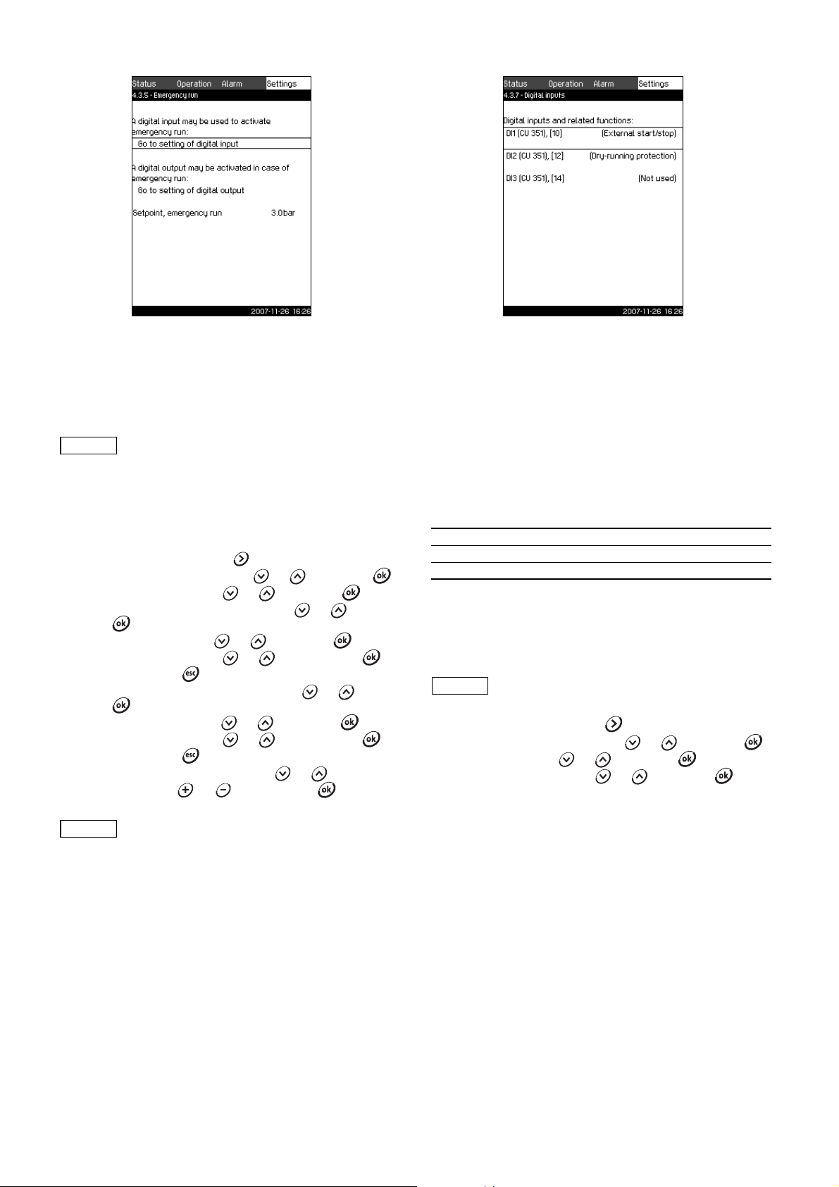
11.7.25 Emergency run (4.3.5)
Caution
Note
Note
11.7.26 Digital inputs (4.3.7)
TM03 8971 4807
Fig. 66 Emergency run
Description
This function is used in booster applications. When this function
has been activated, the pumps will keep running regardless of
warnings or alarms. The pumps will run according to a setpoint
set specifically for this function.
In case of sensor fault, both main and standby
pumps will run at 100 % speed!
Setting range
• Setting of digital input (11.7.26 Digital inputs (4.3.7)).
• Setting of digital output (11.7.31 Digital outputs (4.3.9)).
• Setting of setpoint for emergency run.
Setting via control panel
1. Mark the Settings menu with
2. Mark Secondary functions with or , and press .
3. Mark Emergency run with or , and press .
4. Mark Go to setting of digital input with or , and
press .
5. Select a digital input with or , and press .
6. Mark Emergency run with or , and save with .
7. Return by pressing twice.
8. Mark Go to setting of digital output with or , and
press .
9. Select a digital output with or , and press .
10.Mark Emergency run with or , and save with .
11. Return by pressing twice.
12.Mark Setpoint, emergency run with or .
13.Set the value with or , and save with .
When this function has been set as described
above, it can also be activated via the display
System operating mode (2.1.1).
TM03 2359 4607
Fig. 67 Digital inputs
Description
In this menu, the digital inputs of the CU 351 can be set. Each
input, except DI1, can be activated and related to a certain
function.
As standard, the Control MPC has three digital inputs. If the
Control MPC incorporates an IO 351B module (option), the
number of digital inputs is 12.
In the display, all digital inputs are shown so that their physical
position in the Control MPC can be identified.
Example
DI1 (IO 351-41), [10]:
DI1: Digital input No 1
(IO 351-41): IO 351, GENIbus number 41
[10]: Terminal No 10
For further information on the connection of various digital inputs,
see the wiring diagram supplied with the control cabinet.
Setting range
The digital input to be set is selected in the display Digital inputs
(4.3.7).
DI1 (CU 351) cannot be selected.
Setting via control panel
1. Mark the Settings menu with .
2. Mark Secondary functions with or , and press .
3. Mark Digital inputs or , and press .
4. Select the digital input with or , and press .
40
Page 41

11.7.27 Functions of digital inputs (4.3.7.1)
Note
Note
Fig. 68 Functions of digital inputs
Description
In the displays 4.3.7.1, a function can be related to the digital
inputs.
Setting range
It is possible to select one function in each display:
Function Contact activated
Factory setting
Digital input Function
DI1 (CU 351) [10]
DI2 (CU 351) [12]
Monitoring of water shortage requires a pressure
switch connected to the Control MPC.
11.7.28 Analog inputs (4.3.8)
TM03 8972 4807
External start/stop. Open contact = stop.
Note: Input No 1 cannot be changed.
Monitoring of water shortage (dry-running
protection). Open contact = water shortage
(if the system is supplied with this option).
Not used
Min. duty = Operating mode Min.
Max. duty = Operating mode Max.
User-defined duty
= Operating mode User-
defined
External fault = External fault
Dry-running protection = Water shortage
Flow switch = Flow rate
Reset of alarm = Reset alarms
Emergency run
= Operating mode
Emergency run
Pilot pump fault = Pilot pump fault
Alternative setpoint 2 = Setpoint 2 selected
Alternative setpoint 3 = Setpoint 3selected
Alternative setpoint 4 = Setpoint 4 selected
Alternative setpoint 5 = Setpoint 5 selected
Alternative setpoint 6 = Setpoint 6 selected
Alternative setpoint 7 = Setpoint 7 selected
See the relevant sections for further information about the
functions.
Generally, a closed contact activates the function selected.
Setting via control panel
1. Mark the Settings menu with .
2. Mark Secondary functions with or , and press .
3. Mark Digital inputs with or , and press .
4. Select the digital input with or , and press .
5. Select the desired function with or , and activate it
with .
The activation is indicated by a check mark in the box.
TM03 2356 4607
Fig. 69 Analog inputs
Description
In this display, the analog inputs of the Control MPC can be set.
Each input can be activated and related to a certain function.
As standard, the Control MPC has three analog inputs. If the
Control MPC incorporates an IO 351B module (option), the
number of analog inputs is 5.
In the display, all analog inputs are shown so that their physical
position in the Control MPC can be identified.
A redundant primary sensor can be fitted as back-up for the
primary sensor in order to increase reliability and prevent stop of
operation.
If two sensors are to be redundant, each must
have a separate analog input.
Example
AI1 (CU 351) [51]:
AI1: Analog input No 1
(CU 351): CU 351
[51]: Terminal No 51
Setting range
In the display Analog inputs (4.3.8), the analog input to be set is
selected.
Setting via control panel
1. Mark the Settings menu with .
2. Mark Secondary functions with or , and press .
3. Mark Analog inputs with or , and press .
4. Select the analog input with or , and press .
41
Page 42

11.7.29 Analog inputs (4.3.8.1 to 4.3.8.7)
Note
Fig. 70 Analog inputs
Description
In the displays 4.3.8.1 to 4.3.8.7, analog inputs can be set.
Each display is divided into three parts:
• Setting of input signal, for instance 4-20 mA
• Measured input value, for instance discharge pressure
• Measuring range of the sensor/signal transmitter, for instance
0-16 bar.
Setting range
It is possible to set the following parameters in each display:
• Not used
• Range of input signal, 0-20 mA, 4-20 mA, 0-10 V
• Measured input value
• Sensor range.
Setting via control panel
1. Mark the Settings menu with .
2. Mark Secondary functions with or , and press .
3. Mark Analog inputs with or , and press .
4. Select the analog input with or , and press .
5. Mark the setting of the analog input with or , and
activate it with .
The activation is indicated by a check mark in the box.
If an analog input is deactivated, the display will
only show the top part, i.e. the setting of the
analog input.
If the input is activated, the middle part,
"Measured input value", will be shown. This
makes it possible to relate a function to the
analog input in another display. When the analog
input has been related to a function, CU 351 will
return to the display for setting of analog inputs.
Factory setting
Pressure boosting
Analog input Function
AI1 (CU 351) [51] Discharge pressure
Heating and cooling
Analog input Function
AI1 (CU 351) [51] These are selected in the start-up wizard
11.7.30 Analog inputs and measured value (4.3.8.1.1 to
4.3.8.7.1)
TM03 2357 4607
TM03 8973 4807
Fig. 71 Analog inputs and measured value
Description
In the display Analog inputs and measured value (4.3.8.1.1 to
4.3.8.7.1), a function can be related to the individual analog
inputs.
Setting range
It is possible to select one function per analog input. For further
details, see section 12. Measuring parameters.
• Not used
• 0-100 % signal
• Inlet pressure
• Discharge pressure
• External pressure
• Differential pressure, pump
•Flow rate
• Tank level, discharge side
• Tank level, suction side
• System pressure
• Differential pressure, external
• Tank precharge pressure
• Differential pressure, inlet
• Differential pressure, outlet
• Return pipe temperature, external
• Flow pipe temperature
• Return pipe temperature
• Differential temperature
• Ambient temperature
• Power, pump 1 to 6
• Power, VFD.
Setting via control panel
1. Mark the Settings menu with .
2. Mark Secondary functions with or , and press .
3. Mark Analog inputs with or , and press .
4. Select the analog input with or , and press .
5. Set the range of the analog input with or , and press
.
The activation is indicated by a check mark.
6. Mark Measured input value with or , and press .
Now the display 4.3.8.1.1 appears.
7. Select the input with or , and press .
8. Press to return to display 4.3.8.1.
9. Set the minimum sensor value with or , and save with
.
10.Set the maximum sensor value with or , and save
with .
42
Page 43

11.7.31 Digital outputs (4.3.9)
11.7.32 Functions of digital outputs (4.3.9.1 to 4.3.9.16)
Fig. 72 Digital outputs
Description
In this display, the digital relay outputs of the Control MPC can be
set. Each output can be activated and related to a certain
function.
As standard, the Control MPC has two digital outputs.
If the Control MPC incorporates an IO 351B module (option), the
number of digital outputs is 9.
In the display, all digital outputs are shown so that their physical
position in the Control MPC can be identified.
Example
DO1 (IO 351-41) [71]:
DO1 Digital output No 1
(IO 351-41) IO 351B, GENIbus number 41
[71] Terminal No 71
For further information on the connection of various digital
outputs, see the wiring diagram supplied with the CU 351.
Setting range
In the display Digital outputs (4.3.9), the digital output to be used
is selected.
TM03 2333 4607
Fig. 73 Functions of digital outputs
Description
In the displays Functions of digital outputs (4.3.9.1 to 4.3.9.16), a
function can be related to the individual outputs.
Setting range
It is possible to select one function in each display:
• No function
• Operation, system
• Alarm, system
• Warning, system
• Ready, system
• Water shortage
•Min. pressure
• Max. pressure
• Emergency run
• Pilot pump control
• Pressure relief valve
• Operation, pump 1 to 6
• Alarm, pump 1 to 6
• Alarm, limit 1 exceeded
• Warning, limit 1 exceeded
• Alarm, limit 2 exceeded
• Warning, limit 2 exceeded.
Setting via control panel
1. Mark the Settings menu with .
2. Mark Secondary functions with or , and press .
3. Mark Digital outputs with or , and press .
4. Select the digital output with or , and press .
5. Mark the desired function with or , and activate it with
.
The activation is indicated by a check mark in the box.
Factory setting
TM03 8974 4807
Digital output Function
DO1 (CU 351) [71] Alarm, system
DO2 (CU 351) [74] Operation, system
43
Page 44
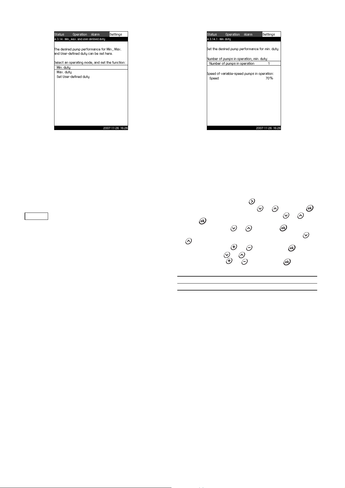
11.7.33 Min., max. and user-defined duty (4.3.14)
Note
11.7.34 Min. duty (4.3.14.1)
Fig. 74 Min., max. and user-defined duty
Description
This function makes it possible to let the pumps run in open loop
at a set pump performance.
Setting range
The CU 351 makes it possible to change between three operating
modes:
1. Min. duty (4.3.14.1).
2. Max. duty (4.3.14.2).
3. User-defined duty (4.3.14.3).
For each of these modes, the number of
operating pumps and the pump performance
(speed) can be set.
TM03 2351 4807
Fig. 75 Min. duty
Description
In all systems, apart from Control MPC-S, minimum duty is only
possible for variable-speed pumps. In Control MPC-S systems,
only the number of pumps running at 100 % speed can be set.
Setting range
• Number of pumps in operation.
• Speed as percentage (25 to 100 %) for variable-speed pumps.
Setting via control panel
1. Mark the Settings menu with .
2. Mark Secondary functions with or , and press .
3. Mark Min., max. and user-defined duty with or , and
press .
4. Mark Min. duty with or , and press .
5. Mark Number of pumps in operation, min. duty with or
.
6. Set the number with or , and save with .
7. Mark Speed with or .
8. Set the value with or , and save with .
Factory setting
Number of pumps in operation during min. duty: 1
Speed as percentage for variable-speed pumps: 70
TM03 2354 4807
44
Page 45
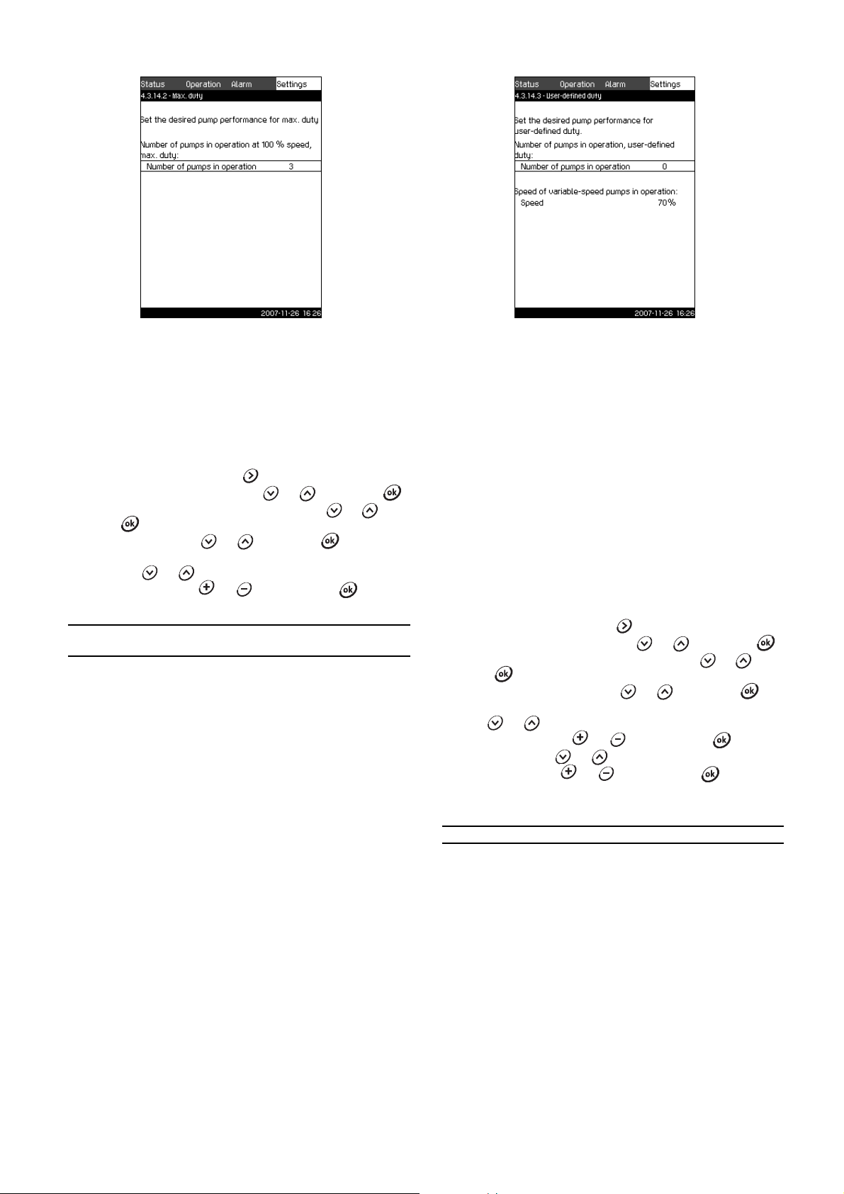
11.7.35 Max. duty (4.3.14.2)
11.7.36 User-defined duty (4.3.14.3)
Fig. 76 Max. duty
Description
The function makes it possible for a set number of pumps to run
at maximum performance when the function is activated.
Setting range
In this display, the number of pumps to run in the operating mode
Max. can be set. All pumps run at 100 % speed.
Setting via control panel
1. Mark the Settings menu with .
2. Mark Secondary functions with or , and press .
3. Mark Min., max. and user-defined duty with or , and
press .
4. Mark Max. duty with or , and press .
5. Mark Number of pumps in operation at 100 % speed, max.
duty with or .
6. Set the number with or , and save with .
Factory setting
Number of pumps in operation
during max. duty:
All pumps (except standby
pumps)
TM03 2353 4807
Fig. 77 User-defined duty
Description
In this display, it is possible to set a user-defined performance,
typically a performance between min. and max. duty.
The function makes it possible to set a pump performance by
selecting the number of pumps to run and the speed of variablespeed pumps.
This function primarily selects the variable-speed pumps. If the
number of selected pumps exceeds the number of variable-speed
pumps, mains-operated pumps are started too.
Setting range
• Number of pumps in operation.
• Speed as percentage for variable-speed pumps.
Note: In Control MPC systems with only variable-speed
pumps, the speed can be set between 25 and 100 %; in
systems with both variable-speed pumps and mains-operated
pumps the speed can be set between 70 and 100 %.
Setting via control panel
1. Mark the Settings menu with .
2. Mark Secondary functions with or , and press .
3. Mark Min., max. and user-defined duty with or , and
press .
4. Mark User-defin ed dut y with or , and press .
5. Mark Number of pumps in operation, user-defined duty
with or .
6. Set the number with or , and save with .
7. Mark Speed with or .
8. Set the value with or , and save with .
Factory setting
The function is not activated, as the following has been set:
TM03 2352 4807
Number of pumps in operation during user-defined duty: 0
45
Page 46

11.7.37 Pump curve data (4.3.19)
Note
Note
Nominal duty point
H
nom
Q
nom
Q
max
H
max
Note
Power, Q0, 100 % speed
Duty point, Q0,
100 % speed
Power, Q0, 50 % speed
Duty point, Q0, 50 % speed
Duty point, Nominal
power, P
nom
Nominal power, P
nom
Fig. 78 Pump curve data
Description
The CU 351 has a number of functions using these pump data:
• Nominal flow rate, Q
• Nominal head, H
• Max. head, H
max
• Max. flow rate, Q
•Power, Q
•Power, Q
, 100 %, speed in kW
0
, 50 % speed, in kW
0
• Nominal power, P
, in m3/h
nom
, in metres
nom
, in metres
in m3/h
max,
, in kW.
nom
Grundfos can supply hydraulic data for CR, CRI,
CRE and CRIE pumps where GSC files can be
downloaded directly to the CU 351.
All other pump types require manual entering of
hydraulic pump data.
a
TM03 8975 4807
TM03 9994 4807TM03 9995 4807TM03 9996 4807
Fig. 80 Reading of Power, Q0, 100 % speed (WebCAPS)
The data are read by means of the pump performance curves
which can be found in WebCAPS on Grundfos’ homepage,
www.grundfos.com. See examples in figs 79 to 82.
If WebCAPS is not accessible, try to bring a pump into the three
duty points: Power, Q
Nominal power, Pnom. Read the power values in displays 1.3 to
1.8, depending on the pump. See section 11.4.8 Pump 1...6 (1.3
to 1.8).
Fig. 79 Reading of Q
The electrical data, "Power, Q0, 100 % speed" and
"Power, Q
, 50 % speed" must be entered
0
manually for all pump types, including CR, CRI,
CRE and CRIE.
For Grundfos E-pumps, the data of input power
(P1) must be entered .
, 100 % speed, Power, Q0, 50 % speed and
0
, H
, H
nom
nom
max
and Q
(WebCAPS)
max
Fig. 81 Reading of Power, Q0, 50 % speed (WebCAPS)
Fig. 82 Reading of Nominal power, P
TM03 9993 4807
Q
nom
and H
are the rated duty point of the
nom
(WebCAPS)
nom
pumps and usually the duty point with the
highest efficiency.
46
Page 47

Setting via control panel
1. Mark the Settings menu with .
2. Mark Secondary functions with or , and press .
3. Mark Pump curve d ata with or , and press .
4. Mark Nominal flow rate Q
with or .
nom
5. Set the value with or , and save with .
6. Mark Nominal head H
with or .
nom
7. Set the value with or , and save with .
8. Mark Max. head H
with or .
max
9. Set the value with or , and save with .
10. Mark Max. flow rate Q
with or .
max
11. Set the value with or , and save with .
12. Mark Power, Q
, 100 % speed with or .
0
13. Set the value with or , and save with .
14. Mark Power, Q
, 50 % speed with or .
0
15. Set the value with or , and save with .
16. Mark Nominal power P
with or .
nom
17. Set the value with or , and save with .
11.7.38 Control source (4.3.20)
Fig. 83 Control source
11.7.39 Fixed inlet pressure (4.3.22)
Fig. 84 Fixed inlet pressure
Description
This function is only used when no inlet pressure sensor is fitted
in the system and the inlet pressure is fixed and known.
If the booster system has a fixed inlet pressure, it can be entered
in this display so that the CU 351 can optimise the performance
and control of the system.
Setting range
A fixed inlet pressure can be set, and the function can be
activated/deactivated.
Setting via control panel
1. Mark the Settings menu with .
2. Mark Secondary functions with or , and press .
3. Mark Fixed inlet pressure with or , and press .
4. Set the inlet pressure with or , and save with .
5. Mark Activated with or , and press . The
activation is indicated by a check mark in the box.
TM03 2342 4807
Factory setting
The function is deactivated.
TM03 8975 4807
Description
Control MPC can be remote-controlled via an external bus
connection (option). See section 11.8.2 GENIbus. Control can
also take place via the bus connection. For further information,
see section 11.8 Data communication.
In this display, the control source, CU 351 or the external bus
connection, is selected.
Setting via control panel
1. Mark the Settings menu with .
2. Mark Secondary functions with or , and press .
3. Mark Control source with or , and press .
4. Select the desired control source with or , and save
with .
Factory setting
The control source is CU 351.
47
Page 48

11.7.40 Flow estimation (4.3.23)
Note
11.7.41 Monitoring functions (4.4)
Fig. 85 Flow estimation
Description
As described in section 11.7.37 Pump curve data (4.3.19), the
CU 351 can optimise operation according to performance curves
and motor data. In this display, curve types are selected which
the CU 351 will use for the optimisation if they are available.
At large flow rates, there may be a considerable head loss
between the pump discharge flange and the pressure sensor. The
loss is caused by non-return valves and pipe bends. To improve
the flow estimation of the system, it is necessary to compensate
for the difference between the measured and the actual
differential pressure across the pump. This is done by entering
the head loss in non-return valves and pipe bends at the rated
flow rate of one pump.
Setting range
• 2nd order QH polynomial
• 5th order QH polynomial
• Power polynomial, QP
• Head loss.
It is possible to select several curve types, as the
CU 351 makes a priority based on the data
available.
Setting via control panel
1. Mark the Settings menu with .
2. Mark Secondary functions with or , and press .
3. Mark Flow estimation with or , and press .
4. Select the curve type by marking one of the lines at the
selection box with or , and press .
Factory setting
All polynomials are selected.
TM03 8977 4807
Fig. 86 Monitoring functions
Description
Control MPC has a series of functions that constantly monitor the
operation of the system.
The primary purpose of the monitoring functions is to ensure that
faults do not damage pumps or the system.
Setting range
The following functions can be selected:
• Dry-running protection (4.4.1)
• Min. pressure (4.4.2)
• Max. pressure (4.4.3)
• External fault (4.4.4)
• Limit 1 and 2 exceeded (4.4.5 and 4.4.6)
• Pumps outside duty range (4.4.7)
• Pressure relief (4.4.8).
Setting via control panel
1. Mark the Settings menu with .
2. Mark Monitoring functions with or , and press .
3. Select the function with or , and press .
TM03 8978 4807
48
Page 49

11.7.42 Dry-running protection (4.4.1)
Fig. 87 Dry-running protection
Description
Dry-running protection is one of the most important monitoring
functions, as bearings and shaft seal may be damaged if the
pumps run dry. Grundfos thus always recommends dry-running
protection.
The function is based on monitoring of the inlet pressure or the
level in a possible tank or pit on the suction side.
Level switches, pressure switches or analog sensors signalling
water shortage at a set level can be used.
There are three different methods for detection of water shortage:
• Pressure switch on suction manifold or float switch/electrode
relay in the supply tank. See section 11.7.43 Dry-running
protection with pressure/level switch (4.4.1.1).
• Measurement of inlet pressure in the suction manifold by
means of an analog pressure transmitter. See section
11.7.44 Dry-running protection with pressure transmitter
(4.4.1.2).
• Measurement of level in the supply tank by means of an
analog level transmitter. See section 11.7.45 Dry-running
protection with level transmitter (4.4.1.3).
Setting via control panel
1. Mark the Settings menu with .
2. Mark Monitoring functions with or , and press .
3. Mark Dry-running protection with or , and press
.
4. Select the method with or , and press .
11.7.43 Dry-running protection with pressure/level switch (4.4.1.1)
TM03 2320 4807
TM03 2329 1109
Fig. 88 Dry-running protection with pressure/level switch
Description
This function is primarily used in booster applications. Dryrunning protection can take place by means of a pressure switch
on the suction manifold or a level switch in a tank on the suction
side.
When the contact is open, the CU 351 will register water
shortage after a time delay of approx. 5 sec. It is possible to set
whether the indication is to be just a warning or an alarm stopping
the pumps.
In the display, it is possible to set whether restart and reset of the
alarm is to be automatic or manual.
Setting range
• Selection of digital input for the function.
• Reaction in case of water shortage: Warning or alarm + stop.
• Restart: Manual or automatic.
Setting via control panel
1. Mark the Settings menu with .
2. Mark Monitoring functions with or , and press .
3. Mark Dry-running protection with or , and press
.
4. Mark Pressure/level switch with or , and press .
5. Mark Go to setting of digital input, and press . Now the
display Digital inputs (4.3.7) appears. Set the input to dry-
running protection. Return with .
6. Mark Warning or Alarm + stop with or , and save
with .
7. Mark Manual or Auto with or , and save with .
Factory setting
The setting is done in the start-up wizard and depends on the
application.
49
Page 50

11.7.44 Dry-running protection with pressure transmitter
Note
(4.4.1.2)
Fig. 89 Dry-running protection with pressure transmitter
Description
Dry-running protection can take place by means of a pressure
transmitter measuring the inlet pressure.
It is possible to set two levels of inlet pressure: Warning and
alarm + stop. In the display, it is possible to set whether restart
and reset of the alarm is to be automatic or manual.
Setting range
• Selection of analog input for the function.
• Activation of the function.
• Inlet pressure level for warning.
• Inlet pressure level for alarm + stop.
• Restart: Manual or automatic.
Setting via control panel
1. Mark the Settings menu with .
2. Mark Monitoring functions with or , and press .
3. Mark Dry-running protection with or , and press
.
4. Mark Measurement, inlet pressure with or , and
press .
5. Mark Go to setting of analog input, and press . Now the
display Analog inputs (4.3.8) appears. Set the input to Inlet
pressure, and save with . Return with .
6. Mark Activated with or , and press .
7. Mark Warning with or . Set the level with or ,
and save with .
8. Mark Alarm + stop with or . Set the level with or
, and save with .
9. Mark Manual or Auto with or , and save with .
If one of the levels is not required, the level value
must be the minimum value of the inlet pressure
transmitter. This deactivates the function.
Factory setting
The setting is done in the start-up wizard and depends on the
application.
11.7.45 Dry-running protection with level transmitter (4.4.1.3)
TM03 8979 4807
Fig. 90 Dry-running protection with level transmitter
Description
Dry-running protection can take place by means of a level
transmitter measuring the level in a tank on the suction side.
It is possible to set two levels: Warning and alarm + stop.
In the display, it is possible to set whether restart and reset of
alarms is to be automatic or manual.
Setting range
• Selection of analog input for the function.
• Activation of the function.
• Tank level for warning.
• Tank level for alarm + stop.
• Restart: Manual or automatic.
Setting via control panel
1. Mark the Settings menu with .
2. Mark Monitoring functions with or , and press .
3. Mark Dry-running protection with or , and press
.
4. Mark Measurement, tank level with or , and press
.
5. Mark Go to setting of analog input, and press . Now the
display Analog inputs (4.3.8) appears. Set the input to Tank
level, suction side. Return with .
6. Mark Activated with or , and press .
7. Mark
Warning with or . Set the level with or ,
and save with .
8. Mark Alarm + stop with or . Set the level with or
, and save with .
9. Mark Manual or Auto with or , and save with .
Factory setting
The function is deactivated.
TM03 8980 4807
50
Page 51

11.7.46 Min. pressure (4.4.2)
11.7.47 Max. pressure (4.4.3)
TM03 8981 4807
Fig. 91 Min. pressure
Description
The discharge pressure is monitored if the application is pressure
boosting. In all other applications, the system pressure is
monitored. The CU 351 will react if the pressure becomes lower
than a set minimum level for an adjustable time.
The minimum pressure can be monitored if a fault indication is
required in situations where the discharge pressure becomes
lower than the set minimum pressure.
It is possible to set whether the indication is to be just a warning
or an alarm stopping the pumps. This may be desirable if Control
MPC is used for an irrigation system where a very low discharge
pressure may be due to pipe fracture and thus an extraordinarily
high consumption and a very low counter-pressure. In such
situations, it is desirable that the system stops and indicates
alarm. This situation will require a manual reset of alarms.
It is possible to set a start-up delay ensuring that the system can
build up pressure before the function is activated. It is also
possible to set a time delay, i.e. for how long time the discharge
pressure may be lower than the set minimum pressure before the
alarm is activated.
Setting range
• Activation of the function.
• Minimum pressure level within the range of the primary
sensor.
• Activation of stop when the pressure falls below the minimum
pressure.
• Time delay at start-up.
• Time delay during operation.
Setting via control panel
1. Mark the Settings menu with .
2. Mark Monitoring functions with or , and press .
3. Mark Min. pressure with or , and press .
4. Mark Activated with or , and press to activate/
deactivate the function.
5. Mark Min. pressure with or . Set the pressure with
or , and save with .
6. Mark Stop at min. pressure with or , and press
to activate/deactivate the function.
7. Mark Time delay of function at start-up with or .
Set the time with or , and save with .
8. Mark Time delay of function during operation with or
. Set the time with or , and save with .
Factory setting
The function is deactivated.
Fig. 92 Max. pressure
Description
The discharge pressure is monitored if the application is pressure
boosting. In all other applications, the system pressure is
monitored. The CU 351 will react if the pressure becomes higher
than a set maximum level.
In certain installations, a too high discharge pressure may cause
damage. It may therefore be necessary to stop all pumps for a
short period if the pressure is too high.
It is possible to set whether the Control MPC is to restart
automatically after the pressure has dropped below the maximum
level, or if the system must be reset manually. Restart will be
delayed by an adjustable time. See section 11.7.1 2 Min. t ime
between start/stop (4.2.1).
Setting range
• Activation of the function.
• Maximum pressure level within the range of the primary
sensor.
• Manual or automatic restart after fault.
Setting via control panel
1. Mark the Settings menu with .
2. Mark Monitoring functions with or , and press .
3. Mark
Max. pressure with or , and press .
4. Mark Activated with or , and press to activate/
deactivate the function.
5. Mark Max. pressure with or . Set the pressure with
or , and save with .
6. Mark Manual or Auto with or . Activate the function
with .
Factory setting
The function is deactivated.
TM03 8982 4807
51
Page 52

11.7.48 External fault (4.4.4)
Note
11.7.49 Limit 1 and 2 exceeded (4.4.5 and 4.4.6)
Fig. 93 External fault
Description
The function is used when the CU 351 is to be able to receive a
fault signal from an external contact. In case of external fault, the
CU 351 indicates warning or alarm. In case of alarm, the system
changes to another manual operating mode, for instance Stop.
Setting range
• Selection of digital input for the function.
• Setting of time delay from closing of the contact until the
CU 351 reacts.
• Reaction in case of external fault: Warning or alarm and
change of operating mode.
• Restart after alarm: Manual or automatic.
Setting via control panel
1. Mark the Settings menu with .
2. Mark Monitoring functions with or , and press .
3. Mark External fault with or , and press .
4. Mark Go to setting of digital input with or , and
press . Now the display Digital inputs (4.3.7) appears.
Set the input to External fault. Return with .
5. Mark Time delay, fault indication with or . Set the
time with or , and save with .
6. Mark Warning with or if only a warning is required in
case of external fault. Activate the function with .
7. Select operating mode with or if the system is to give
alarm and change operating mode in case of external fault.
Activate the function with .
8. Mark Manual or Auto with or . Activate the function
with .
Factory setting
The function is deactivated. If the function is activated, the
following values have been set from factory:
• Time delay: 5 seconds.
• Operating mode in case of alarm: Stop.
• Restart: Manual.
TM03 2313 4807
Fig. 94 Limit 1 exceeded 1
Description
With this function, the CU 351 can monitor set limits of analog
values. It will react if the values exceed the limits. Each limit can
be set as a maximum or minimum value. For each of the
monitored values, a warning limit and an alarm limit must be
defined.
The function makes it possible to monitor two different locations
in a pump system at the same time. For instance the pressure at
a consumer and the pump discharge pressure. This ensures that
the discharge pressure does not reach a critical value.
If the value exceeds the warning limit, a warning is given. If the
value exceeds the alarm limit, the pumps are stopped.
A delay can be set between the detection of an exceeded limit
and the activation of a warning or an alarm. A delay can also be
set for resetting a warning or an alarm.
A warning can be reset automatically or manually.
It is possible to set whether the system is to restart automatically
after an alarm, or if the alarm must be reset manually. Restart can
be delayed by an adjustable time. It is also possible to set a startup delay ensuring that the system reaches a steady state before
the function becomes active.
Setting range
• Activation of an analog input for the function.
• Selection of the measured value to be monitored.
• Setting of limit type (min./max.).
• Setting of warning limit.
• Setting of alarm limit.
Setting via control panel
Analog inputs must be correctly set before the
function is activated. See section 11.7.28 Analog
inputs (4.3.8).
1. Mark the Settings menu with
2. Mark Monitoring functions
with or , and press
3. Mark Limit 1 exceeded 1 or Limit 2 exceeded with or
, and press .
4. Mark Go to setting of analog input with or , and
press .
5. Select the analog input with or , and press .
6. Mark the setting of the analog input with or , and
activate it with .
The activation is indicated by a check mark in the box.
7. Mark Measured value with or , and press .
Now the display 4.3.8.1.1 appears.
8. Select the input with or , and press .
9. Press to return to display 4.3.8.1.
TM03 8983 4807
52
Page 53

10. Set the minimum sensor value with or , and save with
.
11. Set the maximum sensor value with or , and save
with .
12. Return by pressing twice.
13. Mark Measured value to be monitored with or ., and
press . Select the input with or , and press .
14. Return with .
15. Mark Min. limit or Max. limit with or ., and press
.
16. Mark Set delays with or , and press
17. Mark Time delay of function at start-up with or .
Set the time with or , and save with .
18. Mark Time delay of function during operation with or
. Set the time with or , and save with .
19. Mark Time delay of function at reset with or .
Set the time with or , and save with .
20. Return with .
21. Mark Set warning limit with or , and press .
22. Mark Activated with or , and press .
23. Mark Warning limit with or . Set the value with
or , and save with .
24. Mark Manual or Auto with or . Activate the function
with .
25. Return with .
26. Mark Set alarm limit with or , and press .
27. Mark Activated with or , and press .
28. Mark Alarm limit with or . Set the value with or
, and save with .
29. Mark Manual or Auto with or . Activate the function
with .
30. Return with .
31. Mark Activated with or , and press to activate
the function.
Factory setting
The function is deactivated.
11.7.50 Pumps outside duty range (4.4.7)
TM03 8984 4807
Fig. 95 Pumps outside duty range
Description
The function gives a warning if the duty point of the pumps moves
outside the defined range. For instance, if the inlet pressure
becomes lower than a minimum permissible value, thus causing a
risk of cavitation for some pump types.
The warning is given with a set time delay. It is possible to set
whether the warning is to be reset automatically or manually
when the duty point comes within the defined duty range. It is
also possible to set a relay output to be activated when the
warning is given, and to be deactivated when the warning is
reset.
This function requires that the discharge pressure and the inlet
pressure (either measured or configured) or the differential
pressure of the pumps is monitored, and that CU 351 contains
valid pump data from either a GSC file or from manual input.
See section 11.7.37 Pump curve data (4.3.19).
Setting range
• Activation of the function.
• Setting of manual or automatic reset.
• Setting of warning delay.
Setting via control panel
1. Mark the Settings menu with
2. Mark Monitoring functions with or , and press .
3. Mark Pumps outside duty range with or , and press
.
4. Mark Manual or Auto with or , and activate the
function with .
5. Mark Warning delay with or . Set the time with
or , and save with .
6. Mark Activated with or , and press to activate
the function.
Factory setting
The function is deactivated.
53
Page 54

11.7.51 Pressure relief (4.4.8)
4
Band
Warning
delay
Valve opening
pressure
Valve opening pressure
minus band
P [bar]
Time [sec]
1: Solenoid valve opens.
2: Solenoid valve closes.
3: Solenoid valve opens.
4: Warning is activated.
5: Solenoid valve closes, and
warning is reset.
5
32
1
Fig. 96 Pressure relief
Description
This function is primarily used in heating and cooling applications.
The purpose of the function is to reduce the pressure in the
pipework by opening a solenoid valve if it exceeds a set limit.
If the pressure is not reduced within a given time, the solenoid
valve will be closed, and a warning can be given.
Setting via control panel
1. Mark the Settings menu with
2. Mark Monitoring functions with or , and press .
3. Mark Pressure relief with or , and press .
4. Mark Go to setting of digital output with or , and
press .
5. Select a digital output with or , and press .
6. Mark Pressure relief with or , and save with .
7. Return by pressing twice.
8. Mark Pressure to be monitored with or , and press
.
9. Mark Discharge pressure, System pressure or External
pressure with or , and save with .
10. Return with .
11. Mark Valve opening pressure with or . Set the
pressure with or , and save with .
TM03 8986 4807TM03 9206 3607
12.Mark Band, valve opening pressure with or . Set
the pressure with or , and save with .
13.Mark Warning, Deactivated or Activated with or ,
and press .
14.Mark Delay with or . Set the time with or ,
and save with . (Only to be set if warning has been
activated.)
15.Mark Activated with or , and press activate the
function.
Factory setting
The function is deactivated.
Setting range
• Setting of digital output.
• Setting of pressure to be monitored.
• Setting of valve opening pressure.
• Setting of band for valve opening pressure.
• Setting of warning or alarm.
• Activation of the function.
Fig. 97 Pressure relief
54
Page 55
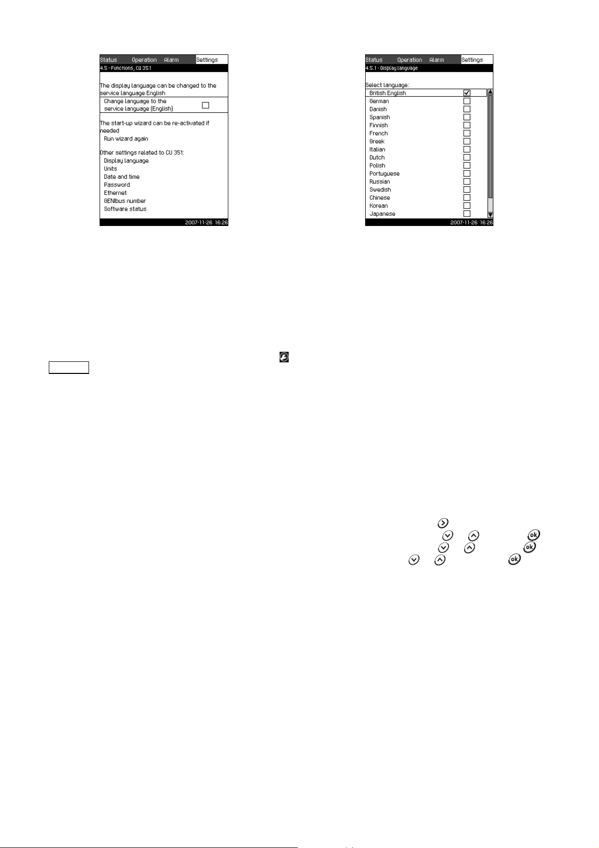
11.7.52 Functions, CU 351 (4.5)
Note
11.7.53 Display language (4.5.1)
Fig. 98 Functions, CU 351
Description
In this submenu, it is possible to make the basic settings of the
CU 351.
CU 351 comes with most of these settings, or they are made at
start-up and normally not to be changed.
The service language, English, can be activated for service
purposes. If no buttons are touched for 15 minutes, the display
will return to the language selected at start-up or to the language
set in section 11.7.53 Display language (4.5.1).
If the service language is selected, the symbol
will be shown to the right of the top line of all
displays.
Setting range
• Activation of service language, British English.
• Re-activation of start-up wizard.
(After start-up, the wizard is inactive.)
• Selection of display language.
• Selection of display units.
• Setting date and time.
• Selection of password for the menus Operation and Settings.
• Setting of Ethernet communication.
• Setting of GENIbus number.
• Reading of software status.
TM03 2295 4807
Fig. 99 Display language
Description
Here the language for the CU 351 display is selected.
Setting range
• British English
•German
•Danish
•Spanish
• Finnish
•French
• Greek
•Italian
•Dutch
•Polish
• Portuguese
•Russian
• Swedish
• Chinese
• Korean
• Japanese
• Czech
•Turkish
Setting via control panel
1. Mark the Settings menu with .
2. Mark Functions, CU 351 with or , and press .
3. Mark Display language with or , and press .
4. Select language with or , and save with .
Factory setting
The display language is British English. It can be changed at
start-up.
TM03 8987 4807
55
Page 56

11.7.54 Display units (4.5.2)
Note
Fig. 100 Display units
Description
In this display, it is possible to select units for the various
parameters.
For the basic setting, it is possible to select between SI and US
units. It is also possible to select other units for the individual
parameters.
Setting range
TM03 8988 4807
Fig. 101 Example of selection of display units
6. Select the unit with or , and save with .
A check mark shows that the unit has been selected.
Factory setting
The setting is done in the start-up wizard and depends on the
application.
TM03 2310 4807
Parameter
Pressure bar psi
Differential pressure m psi
Basic setting
SI US
Possible units
kPa, MPa, mbar,
bar, m, psi
kPa, MPa, mbar,
bar, m, psi
Head m ft m, cm, ft, in
Level m ft m, cm, ft, in
3
m
Flow rate m
Volume m
3
/h gpm
3
gal l, m3, gal, yd
Specific energy kWh/m3Wh/gal
/s, m3/h, l/s, gpm,
3
yd
/s, yd3/min, yd3/h
kWh/m
3
3
, Wh/gal,
Wh/kgal, BTU/gal,
HPh/gal
Temperature °C °F K, °C, °F
Differential temperature K K K
Power kW HP W, kW, MW, HP
Energy kWh kWh
kWh, MWh, BTU,
HPh
If units are changed from SI to US or vice versa,
all individually set parameters will be changed to
the basic setting in question.
Setting via control panel
1. Mark the Settings menu with .
2. Mark Functions, CU 351 with or , and press .
3. Mark Units with or , and press .
4. Select the unit with or , and save with .
A check mark shows that the unit has been selected.
5. Select the measuring parameter with or , and press
to open the display for the measuring parameter.
See the example.
56
Page 57

11.7.55 Date and time (4.5.3)
Note
Note
11.7.56 Passwords (4.5.4)
TM03 8989 4807
Fig. 102 Date and time
Description
In this display, date and time are set as well as how they are to be
shown in the display.
The clock has a built-in rechargeable voltage supply which can
supply the clock for up to 20 days if the voltage supply to the
Control MPC is interrupted.
If the clock is without voltage for more than 20 days, it must be
set again.
Setting range
The date can be set as day, month and year. The time can be set
as a 24-hour clock showing hours and minutes.
There are three formats.
Examples of format
2005-09-27 13:49
27-09-2005 13:49
9/27/2005 1:49pm
It is also possible to select if Sunday or Monday is to be the first
day of week.
Setting via control panel
1. Mark the Settings menu with .
2. Mark Functions, CU 351 with or , and press .
3. Mark Date and time with or , and press .
4. Mark Day, Month and Year with or , and set the date
with or . Save with .
5. Mark Hours and Minutes with or , and set the time
with or . Save with .
6. Select the format with or , and save with .
7. Mark First day of week, Sunday or Monday with or ,
and save with
Factory setting
Local time.
If the Control MPC has been without voltage for
more than 20 days since it left the factory, the
clock may have returned to the original setting:
01-01-2005 0:00.
Date and time may have been changed during the
setting of Control MPC.
There is no automatic changeover to/from
daylight-saving time.
TM03 2899 4807
Fig. 103 Passwords
Description
In this display, it is possible to limit the access to the Operation
and Settings menus by means of a password. If the access is
limited, it is not possible to view or set any parameters in the
menus.
The password must consist of four digits and may be used for
both menus.
If you have forgotten the password(s), contact
Grundfos.
Setting via control panel
1. Mark the Settings menu with .
2. Mark Functions, CU 351 with or , and press .
3. Mark Password with or , and press .
4. Mark the password to be activated, and press .
5. Mark Enter password, and press .
Now the first digit of the password is flashing.
6. Select the digit with or , and save with .
Now the second digit of the password is flashing.
7. Repeat steps 4 to 6 if it is necessary to activate the other
password.
Factory setting
Both passwords are deactivated. If a password is activated, the
factory setting will be "1234".
57
Page 58

11.7.57 Ethernet (4.5.5)
11.7.59 Software status (4.5.9)
Fig. 104 Ethernet
Description
The CU 351 is equipped with an Ethernet connection for
communication with a computer, either directly or via Internet.
For further information, see section 11.8.1 Ethernet.
11.7.58 GENIbus number (4.5.6)
Fig. 105 GENIbus number
TM03 2298 4807TM03 2297 4807
Fig. 106 Software status
Description
This display shows the status of the software installed in the
CU 351. Furthermore, the version code and the product numbers
of configuration files (GSC) read into the unit are shown.
As it is a status display, no settings can be made.
TM03 2296 4807
Description
CU 351 can communicate with external units via an RS-485
interface (option). For further information, see fig. 107 and
section 11.8.2 GENIbus.
Communication is carried out according to the Grundfos bus
protocol, GENIbus, and enables connection to a building
management system or another external control system.
Operating parameters, such as setpoint and operating mode, can
be set via the bus signal. Furthermore, status about important
parameters, such as current value and input power, and fault
indications can be read from the CU 351.
Contact Grundfos for further information.
Setting range
The number can be set between 1 and 64.
Setting via control panel
1. Mark the Settings menu with .
2. Mark Functions, CU 351 with or , and press .
3. Mark GENIbus number with or , and press .
4. Select the number with or , and save with .
Factory setting
No number is set ("–").
58
Page 59
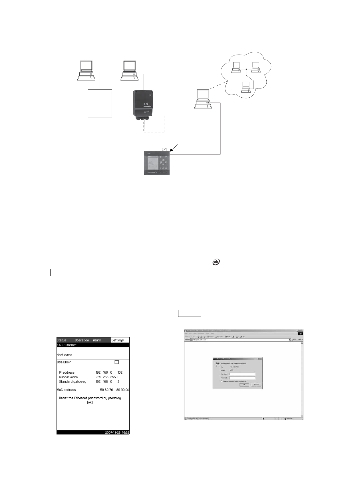
11.8 Data communication
Intranet
Internet
External GENIbus connection
Ethernet connection
External
GENIbus module
(factory option)
Grundfos CIU
communication
interface
Third-
party
gateway
Note
Note
CU 351 is equipped with a hardware enabling communication
with external units, such as a computer, via an external GENIbus
or Ethernet connection.
Fig. 107 Data communication via external GENIbus and Ethernet connection
TM03 2044 1009
11.8.1 Ethernet
Ethernet is the most widely used standard for local networks
(LAN). The standardisation of this technology has created some
of the easiest and cheapest ways of creating communication
between electrical units, for instance between computers or
between computers and control units.
The web server of the CU 351 makes it possible to connect a
computer to the CU 351 via an Ethernet connection. The user
interface can thus be exported from the CU 351 to a computer so
that the CU 351 and consequently the system can be monitored
and controlled externally.
Grundfos recommends that you protect the
connection to the CU 351 according to your
safety requirements in consultation with the
system administrator.
In order to use the web server, you must know the IP address of
the CU 351. All network units must have a unique IP address in
order to communicate with each other. The IP address of the
CU 351 from factory is 192.168.0.102.
Alternatively to the factory-set IP address, it is possible to use a
dynamic assignment of IP address. This is possible by activating
a DHCP (Dynamic Host Configuration Protocol) either directly in
the CU 351 or via the web server. See the example in fig. 108.
Dynamic assignment of an IP address for the CU 351 requires a
DHCP server in the network. The DHCP server assigns a number
of IP addresses to the electrical units and makes sure that two
units do not receive the same IP address.
A traditional Internet browser is used for connection to the web
server of the CU 351.
If you want to use the factory-set IP address, no changes are
required in the display. Open the Internet browser and enter the
IP address of the CU 351.
In order to use dynamic assignment, the function must be
activated. Click Use DHCP in the menu line. A check mark
next to the menu line shows that activation has been made.
After activation in the display, open the Internet and enter the
host name of the CU 351 instead of the IP address. The Internet
browser will now try to connect to the CU 351. The host name can
be read in the display, but can only be changed by either a GSCfile (configuration file) or via a web server. See Change of
network setting on page 60.
To use DHCP, a host name is required.
This is the first display shown when connecting to the CU 351.
Fig. 108 Example of setting of Ethernet
TM03 2298 4807
TM03 2048 3505
Fig. 109 Connection to CU 351
59
Page 60

Factory setting
User name:admin
Password: admin
When user name and password have been entered, a Java
Runtime Environment application starts up in the CU 351,
provided that it has been installed on the computer in question.
If this is not the case, but the computer is connected to Internet,
then use the link on the screen to download and install the Java
Runtime Environment application.
Fig. 110 Display with link to the JavaScript
®
program
The Java Runtime Environment application will then export the
CU 351 user interface (including display and operating panel) to
the computer screen. It is now possible to monitor and control the
CU 351 from the computer.
Change of network setting
When connection to the web server of the CU 351 has been
established, it is possible to change the network setting.
Fig. 112 Change of network setting
TM03 2049 3505TM03 2047 3505
1. Press the icon >Network admin.
2. Enter the changes.
3. Press Submit to activate the changes.
Change of password
TM03 2050 3505TM03 2051 3505
Fig. 111 Network setting
60
Fig. 113 Change of password
1. Press the icon >Change password.
2. Enter the new password.
3. Press Submit to activate the new password.
11.8.2 GENIbus
By installing a GENIbus module in the CU 351 it is possible to
connect the system to an external network. The connection can
take place via a GENIbus-based network or a network based on
another fieldbus protocol via a gateway. See examples in fig. 107.
For further information, contact Grundfos.
The gateway may be a Grundfos CIU communication interface or
a third-party gateway. For further information on the CIU, see
WebCAPS, or contact Grundfos.
Page 61

12. Measuring parameters
1
2
5
4
14
6
11
5
7
12
13
10
3
14
15
16
17
7
11
12
5
6
13
10
3
15
14
16
17
9
8
12.1 Transmitter types
The transmitter types in the table below can be used for the
measurement of values in the system.
Abbreviation Transmitter
DPT Differential pressure transmitter
DTT Differential temperature transmitter
FT Flow transmitter
LT Level transmitter
PT Pressure transmitter
TT Temperature transmitter
12.2 Parameter list
The table below shows which measured values the CU 351 can
receive via its analog inputs. Figures 114 to 115 117 show where
the values can be measured.
No Parameter
1Flow rate
2 Discharge pressure
3 Differential pressure, external
4 Inlet pressure
5 Differential pressure, pump
6 Differential pressure, inlet
7 Differential pressure, outlet
8 Tank level, discharge side
9 Tank level, suction side
10 Return pipe temperature, external
11 Flow pipe temperature
12 Return pipe temperature
13 Differential temperature
14 External pressure
15 Series 2000, differential pressure
16 Series 2000, flow rate
17 System pressure
Not shown Ambient temperature*
Not shown 0-100 % signal**
TM03 9964 4707TM03 9965 4707TM03 8824 2607
Fig. 115 Heating and cooling, pumps in flow pipe
Fig. 116 Heating and cooling, pumps in return pipe
Fig. 117 Level monitoring
* The ambient temperature is typically the temperature in the
room where the Control MPC is located.
** A 0-100 % signal from an external controller. It can for instance
be a 0-10 V signal.
Fig. 114 Pressure boosting
TM03 8823 3507
61
Page 62

13. Fault finding chart
Warnin g
Before making any connections in pumps, terminal boxes or breaker cabinet, make sure that the electricity supply
has been switched off for at least 5 minutes and that it cannot be accidentally switched on.
Fault Possible cause Remedy
Replace the primary sensor. Transmitters
with 0-20 mA or 4-20 mA output signals are
monitored by the Control MPC.
Repair or replace the cable.
Connect the electricity supply.
Contact Grundfos.
The Control MPC is stopped and cannot
restart.
Primary sensor fault
- Primary sensor is defective.
- Cable is broken or short-circuited.
CU 351 fault
- Electricity supply disconnected.
- CU 351 defective.
Electricity supply disconnected. Connect the electricity supply.
Main switch switched off. Switch in the main switch.
Main switch is defective. Replace the main switch.
Motor protection is activated. Contact Grundfos.
62
Page 63

14. Maintenance
Note
Note
Note
Note
Subject to alterations.
Warnin g
Before starting work on the Control MPC, make
sure that the electricity supply has been
switched off. Lock the main switch with a
padlock to ensure that it cannot be accidentally
switched on.
14.1 CU 351
The CU 351 is maintenance-free. It must be kept clean and dry.
Protect it against direct sunlight. Furthermore, the CU 351 must
not be outside the ambient temperature range. See section
16. Technical data.
15. Taking out of operation
Switch off the main switch to take the Control MPC out of
operation.
Warnin g
The conductors in front of the main switch are
still energised. Lock the main switch with a
padlock to ensure that it cannot be accidentally
switched on.
Digital outputs (relay outputs)
Maximum contact load: 240 VAC, 2 A
Minimum contact load: 5 VDC, 10 mA
All digital outputs are potential-free relay contacts.
Some outputs have a common C terminal. For
further information, see the wiring diagram
supplied with the Control MPC.
Inputs for PTC sensor/thermal switch
For PTC sensors to DIN 44082. Thermal switches can also be
connected.
Open circuit voltage: 12 VDC ±15 %
Closed circuit current: 2.6 mA, DC
Inputs for PTC sensors are electrically separated
from the other inputs and outputs of the Control
MPC.
18. Related documents
Further product information about Control MPC and pumps that
can be controlled by the Control MPC are available in WebCAPS
on Grundfos’ homepage, www.grundfos.com.
16. Technical data
16.1 Temperature
Ambient temperature: 0 °C to +40 °C
16.2 Relative humidity
Max. relative humidity: 95 %
17. Electrical data
Supply voltage
See nameplate of the Control MPC.
Backup fuse
See the wiring diagram supplied with the Control MPC.
Digital inputs
Open circuit voltage: 24 VDC
Closed circuit current: 5 mA, DC
Frequency range: 0-4 Hz
All digital inputs are supplied with PELV voltage
(Protective Extra-Low Voltage).
Analog inputs
0-20 mA
Input current and voltage:
Tolerance: ±3.3 % of full scale
Repetitive accuracy: ±1% of full scale
Input resistance, current: < 250 Ω
Input resistance, voltage, CU 351: 10 kΩ ±10 %
Input resistance, voltage, IO 351: > 50 kΩ ± 10 %
Supply to sensor:
4-20 mA
0-10 V
24 V, maximum 50 mA,
short-circuit protected
19. Disposal
This product or parts of it must be disposed of in an
environmentally sound way:
1. Use the public or private waste collection service.
2. If this is not possible, contact the nearest Grundfos company
or service workshop.
All analog inputs are supplied with PELV voltage
(Protective Extra-Low Voltage).
63
Page 64

646566
Page 65

Page 66

Page 67

Argentina
Bombas GRUNDFOS de Argentina S.A.
Ruta Panamericana km. 37.500 Lote
34A
1619 - Garin
Pcia. de Buenos Aires
Phone: +54-3327 414 444
Telefax: +54-3327 411 111
Australia
GRUNDFOS Pumps Pty. Ltd.
P.O. Box 2040
Regency Park
South Australia 5942
Phone: +61-8-8461-4611
Telefax: +61-8-8340 0155
Austria
GRUNDFOS Pumpen Vertrieb
Ges.m.b.H.
Grundfosstraße 2
A-5082 Grödig/Salzburg
Tel.: +43-6246-883-0
Telefax: +43-6246-883-30
Belgium
N.V. GRUNDFOS Bellux S.A.
Boomsesteenweg 81-83
B-2630 Aartselaar
Tél.: +32-3-870 7300
Télécopie: +32-3-870 7301
Belorussia
Представительство ГРУНДФОС в
Минске
220123, Минск,
ул. В. Хоружей, 22, оф. 1105
Тел.: +(37517) 233 97 65,
Факс: +(37517) 233 97 69
E-mail: grundfos_minsk@mail.ru
Bosnia/Herzegovina
GRUNDFOS Sarajevo
Trg Heroja 16,
BiH-71000 Sarajevo
Phone: +387 33 713 290
Telefax: +387 33 659 079
e-mail: grundfos@bih.net.ba
Brazil
Mark GRUNDFOS Ltda.
Av. Humberto de Alencar Castelo
Branco, 630
CEP 09850 - 300
São Bernardo do Campo - SP
Phone: +55-11 4393 5533
Telefax: +55-11 4343 5015
Bulgaria
GRUNDFOS Pumpen Vertrieb
Representative Office - Bulgaria
Bulgaria, 1421 Sofia
Lozenetz District
105-107 Arsenalski blvd.
Phone: +359 2963 3820, 2963 5653
Telefax: +359 2963 1305
Canada
GRUNDFOS Canada Inc.
2941 Brighton Road
Oakville, Ontario
L6H 6C9
Phone: +1-905 829 9533
Telefax: +1-905 829 9512
China
GRUNDFOS Pumps (Shanghai) Co. Ltd.
51 Floor, Raffles City
No. 268 Xi Zang Road. (M)
Shanghai 200001
PRC
Phone: +86-021-612 252 22
Telefax: +86-021-612 253 33
Croatia
GRUNDFOS predstavništvo Zagreb
Cebini 37, Buzin
HR-10010 Zagreb
Phone: +385 1 6595 400
Telefax: +385 1 6595 499
Czech Republic
GRUNDFOS s.r.o.
Čajkovského 21
779 00 Olomouc
Phone: +420-585-716 111
Telefax: +420-585-716 299
Denmark
GRUNDFOS DK A/S
Martin Bachs Vej 3
DK-8850 Bjerringbro
Tlf.: +45-87 50 50 50
Telefax: +45-87 50 51 51
E-mail: info_GDK@grundfos.com
www.grundfos.com/DK
Estonia
GRUNDFOS Pumps Eesti OÜ
Peterburi tee 92G
11415 Tallinn
Tel: + 372 606 1690
Fax: + 372 606 1691
Finland
OY GRUNDFOS Pumput AB
Mestarintie 11
FIN-01730 Vantaa
Phone: +358-3066 5650
Telefax: +358-3066 56550
France
Pompes GRUNDFOS Distribution S.A.
Parc d’Activités de Chesnes
57, rue de Malacombe
F-38290 St. Quentin Fallavier (Lyon)
Tél.: +33-4 74 82 15 15
Télécopie: +33-4 74 94 10 51
Germany
GRUNDFOS GMBH
Schlüterstr. 33
40699 Erkrath
Tel.: +49-(0) 211 929 69-0
Telefax: +49-(0) 211 929 69-3799
e-mail: infoservice@grundfos.de
Service in Deutschland:
e-mail: kundendienst@grundfos.de
Greece
GRUNDFOS Hellas A.E.B.E.
20th km. Athinon-Markopoulou Av.
P.O. Box 71
GR-19002 Peania
Phone: +0030-210-66 83 400
Telefax: +0030-210-66 46 273
Hong Kong
GRUNDFOS Pumps (Hong Kong) Ltd.
Unit 1, Ground floor
Siu Wai Industrial Centre
29-33 Wing Hong Street &
68 King Lam Street, Cheung Sha Wan
Kowloon
Phone: +852-27861706 / 27861741
Telefax: +852-27858664
Hungary
GRUNDFOS Hungária Kft.
Park u. 8
H-2045 Törökbálint,
Phone: +36-23 511 110
Telefax: +36-23 511 111
India
GRUNDFOS Pumps India Private Limited
118 Old Mahabalipuram Road
Thoraipakkam
Chennai 600 096
Phone: +91-44 2496 6800
Indonesia
PT GRUNDFOS Pompa
Jl. Rawa Sumur III, Blok III / CC-1
Kawasan Industri, Pulogadung
Jakarta 13930
Phone: +62-21-460 6909
Telefax: +62-21-460 6910 / 460 6901
Ireland
GRUNDFOS (Ireland) Ltd.
Unit A, Merrywell Business Park
Ballymount Road Lower
Dublin 12
Phone: +353-1-4089 800
Telefax: +353-1-4089 830
Italy
GRUNDFOS Pompe Italia S.r.l.
Via Gran Sasso 4
I-20060 Truccazzano (Milano)
Tel.: +39-02-95838112
Telefax: +39-02-95309290 / 95838461
Japan
GRUNDFOS Pumps K.K.
Gotanda Metalion Bldg., 5F,
5-21-15, Higashi-gotanda
Shiagawa-ku, Tokyo
141-0022 Japan
Phone: +81 35 448 1391
Telefax: +81 35 448 9619
Korea
GRUNDFOS Pumps Korea Ltd.
6th Floor, Aju Building 679-5
Yeoksam-dong, Kangnam-ku, 135-916
Seoul, Korea
Phone: +82-2-5317 600
Telefax: +82-2-5633 725
Latvia
SIA GRUNDFOS Pumps Latvia
Deglava biznesa centrs
Augusta Deglava ielā 60, LV-1035, Rīga,
Tālr.: + 371 714 9640, 7 149 641
Fakss: + 371 914 9646
Lithuania
GRUNDFOS Pumps UAB
Smolensko g. 6
LT-03201 Vilnius
Tel: + 370 52 395 430
Fax: + 370 52 395 431
Malaysia
GRUNDFOS Pumps Sdn. Bhd.
7 Jalan Peguam U1/25
Glenmarie Industrial Park
40150 Shah Alam
Selangor
Phone: +60-3-5569 2922
Telefax: +60-3-5569 2866
México
Bombas GRUNDFOS de México S.A. de
C.V.
Boulevard TLC No. 15
Parque Industrial Stiva Aeropuerto
Apodaca, N.L. 66600
Phone: +52-81-8144 4000
Telefax: +52-81-8144 4010
Netherlands
GRUNDFOS Netherlands
Veluwezoom 35
1326 AE Almere
Postbus 22015
1302 CA ALMERE
Tel.: +31-88-478 6336
Telefax: +31-88-478 6332
e-mail: info_gnl@grundfos.com
New Zealand
GRUNDFOS Pumps NZ Ltd.
17 Beatrice Tinsley Crescent
North Harbour Industrial Estate
Albany, Auckland
Phone: +64-9-415 3240
Telefax: +64-9-415 3250
Norway
GRUNDFOS Pumper A/S
Strømsveien 344
Postboks 235, Leirdal
N-1011 Oslo
Tlf.: +47-22 90 47 00
Telefax: +47-22 32 21 50
Poland
GRUNDFOS Pompy Sp. z o.o.
ul. Klonowa 23
Baranowo k. Poznania
PL-62-081 Przeźmierowo
Tel: (+48-61) 650 13 00
Fax: (+48-61) 650 13 50
Portugal
Bombas GRUNDFOS Portugal, S.A.
Rua Calvet de Magalhães, 241
Apartado 1079
P-2770-153 Paço de Arcos
Tel.: +351-21-440 76 00
Telefax: +351-21-440 76 90
România
GRUNDFOS Pompe România SRL
Bd. Biruintei, nr 103
Pantelimon county Ilfov
Phone: +40 21 200 4100
Telefax: +40 21 200 4101
E-mail: romania@grundfos.ro
Russia
ООО Грундфос
Росс ия, 109544 Москва, ул. Школьная
39
Тел. (+7) 495 737 30 00, 564 88 00
Факс (+7) 495 737 75 36, 564 88 11
E-mail
grundfos.moscow@grundfos.com
Serbia
GRUNDFOS Predstavništvo Beograd
Dr. Milutina Ivkovića 2a/29
YU-11000 Beograd
Phone: +381 11 26 47 877 / 11 26 47
496
Telefax: +381 11 26 48 340
Singapore
GRUNDFOS (Singapore) Pte. Ltd.
24 Tuas West Road
Jurong Town
Singapore 638381
Phone: +65-6865 1222
Telefax: +65-6861 8402
Slovenia
GRUNDFOS PUMPEN VERTRIEB
Ges.m.b.H.,
Podružnica Ljubljana
Šlandrova 8b, SI-1231 Ljubljana-Črnuče
Phone: +386 1 568 0610
Telefax: +386 1 568 0619
E-mail: slovenia@grundfos.si
Spain
Bombas GRUNDFOS España S.A.
Camino de la Fuentecilla, s/n
E-28110 Algete (Madrid)
Tel.: +34-91-848 8800
Telefax: +34-91-628 0465
Sweden
GRUNDFOS AB
Box 333 (Lunnagårdsgatan 6)
431 24 Mölndal
Tel.: +46(0)771-32 23 00
Telefax: +46(0)31-331 94 60
Switzerland
GRUNDFOS Pumpen AG
Bruggacherstrasse 10
CH-8117 Fällanden/ZH
Tel.: +41-1-806 8111
Telefax: +41-1-806 8115
Taiwan
GRUNDFOS Pumps (Taiwan) Ltd.
7 Floor, 219 Min-Chuan Road
Tai ch un g, Taiwa n, R.O. C.
Phone: +886-4-2305 0868
Telefax: +886-4-2305 0878
Thailand
GRUNDFOS (Thailand) Ltd.
92 Chaloem Phrakiat Rama 9 Road,
Dokmai, Pravej, Bangkok 10250
Phone: +66-2-725 8999
Telefax: +66-2-725 8998
Turkey
GRUNDFOS POMPA San. ve Tic. Ltd.
Sti.
Gebze Organize Sanayi Bölgesi
Ihsan dede Caddesi,
2. yol 200. Sokak No. 204
41490 Gebze/ Kocaeli
Phone: +90 - 262-679 7979
Telefax: +90 - 262-679 7905
E-mail: satis@grundfos.com
Ukraine
ТОВ ГРУНДФОС УКРАЇНА
01010 Київ, Вул. Московська 8б,
Тел.:(+38 044) 390 40 50
Фах.: (+38 044) 390 40 59
E-mail: ukraine@grundfos.com
United Arab Emirates
GRUNDFOS Gulf Distribution
P.O. Box 16768
Jebel Ali Free Zone
Dubai
Phone: +971-4- 8815 166
Telefax: +971-4-8815 136
United Kingdom
GRUNDFOS Pumps Ltd.
Grovebury Road
Leighton Buzzard/Beds. LU7 8TL
Phone: +44-1525-850000
Telefax: +44-1525-850011
U.S.A.
GRUNDFOS Pumps Corporation
17100 West 118th Terrace
Olathe, Kansas 66061
Phone: +1-913-227-3400
Telefax: +1-913-227-3500
Usbekistan
Представительство ГРУНДФОС в
Ташкенте
700000 Та шкент ул.Усма на Носира 1-й
тупик 5
Телеф он: (3712) 55-68-15
Факс: (3712) 53-36-35
Addresses revised 02.04.2009
Page 68

Being responsible is our foundation
Thinking ahead makes it possible
Innovation is the essence
96768036 1209
Repl. 96768036 0509
www.grundfos.com
GB
The name Grundfos, the Grundfos logo, and the payoff Be–Think–Innovate are registrated trademarks
owned by Grundfos Management A/S or Grundfos A/S, Denmark. All rights reserved worldwide.
 Loading...