

Page 1

Conlift1 LS
Installation and operating instructions
GRUNDFOS INSTRUCTIONS
Page 2
English (GB) Installation and operating instructions
English (GB)
Original installation and operating instructions
These installation and operating instructions
describe Grundfos Conlift.
Sections 1-4 give the information necessary to be
able to unpack, install and start up the product in a
safe way.
Sections 5-10 give important information about the
product, as well as information on service, fault
finding and disposal of the product.
1. Symbols used in this document
1.1 Warnings against hazards involving
CONTENTS
Page
1. Symbols used in this document
1.1 Warnings against hazards involving risk of death or personal injury
1.2 Other important notes
2. Receiving the product
2.1 Transporting the product
3. Installing the product
3.1 Mechanical installation
3.2 Electrical installation
4. Starting up the product
4.1 Checking the alarm
5. Product introduction
5.1 Product description
5.2 Intended use
5.3 Operating mode
5.4 Handling of condensates
5.5 Marking and approvals
5.6 Accessories
6. Control functions
7. Servicing the product
7.1 Maintenance
7.2 Service
7.3 Contaminated products
8. Fault finding the product
9. Technical data
10. Disposal
2
2
3
3
3
3
The text accompanying the three hazard symbols
3
DANGER, WARNING and CAUTION is structured in
3
the following way:
4
4
5
5
5
5
5
5
6
6
6
6
6
7
8
9
9
risk of death or personal injury
DANGER
Indicates a hazardous situation which, if
not avoided, will result in death or serious
personal injury.
WARNING
Indicates a hazardous situation which, if
not avoided, could result in death or
serious personal injury.
CAUTION
Indicates a hazardous situation which, if
not avoided, could result in minor or
moderate personal injury.
Read this document before installing the
product. Installation and operation must
comply with local regulations and accepted
codes of good practice.
This appliance can be used by children
aged from 8 years and above and persons
with reduced physical, sensory or mental
capabilities or lack of experience and
knowledge if they have been given
supervision or instruction concerning use
of the appliance in a safe way and
understand the hazards involved.
Children shall not play with the appliance.
Cleaning and user maintenance shall not
be made by children without supervision.
2
Page 3

1.2 Other important notes
3.2 Electrical installation
A blue or grey circle with a white graphical
symbol indicates that an action must be
taken.
A red or grey circle with a diagonal bar,
possibly with a black graphical symbol,
indicates that an action must not be taken
or must be stopped.
If these instructions are not observed, it
may result in malfunction or damage to the
equipment.
Tips and advice that make the work easier.
2. Receiving the product
2.1 Transporting the product
WARNING
Harm of body
Death or serious personal injury
- Stack maximum two pallets together
under transportation.
3. Installing the product
Installation must be carried out by
specially trained persons and according to
local regulations.
If not already integrated, a water trap (emission trap)
must be fitted in all inlets.
The Conlift is not designed for outdoor use.
3.1 Mechanical installation
See also the quick guide supplied with the Conlift.
When installing the Conlift, observe the following:
• The condensate must run freely into the lifting
station.
• The cooling slots in the motor cover must not be
covered.
• The lifting station must be easily accessible in
order to facilitate maintenance.
• The lifting station must be installed in a
well-illuminated and -ventilated room.
Electrical connection must be carried out
by an authorized electrician.
Carry out the electrical connection according to local
regulations.
Check that the supply voltage and frequency
correspond to the values stated on the nameplate.
The power supply cable has a Schuko plug or a free
cable end. The cable has a length of 2 metres.
WARNING
Electric shock
Death or serious personal injury
- Make sure that the protective earth from
the socket outlet is connected to the
protective earth in the pump.
Make sure that the plug has the same
PE connection system as the socket
outlet or else use a suitable adapter.
The product must be connected to a main
switch with a minimum contact gap of 3
mm in all poles.
We recommend to provide the permanent installation
with an earth leakage circuit breaker (ELCB) with a
tripping current < 30 mA.
The electrical connection of a cable with a
free cable end must be carried out by an
authorised electrician.
English (GB)
3
Page 4

3.2.1 Cable to condensate source or external
1
2
3
Brown
Blue
1 = COM1
2 = NO4
3 = NC2
English (GB)
alarm
The Conlift has a safety overflow switch which can
be connected to the condensate source or to an
external alarm system. The switch is connected to an
alarm cable with free cable end.
Alarm systems with a control voltage of 250 VAC, 2.5
A, can be used.
On delivery, the alarm cable is connected to
terminals COM1 (brown) and NC2(blue) of the safety
overflow switch. See fig. 1.
Fig. 1 Wiring diagram
The alarm cable can be connected in two ways,
depending on application:
• Shutdown of condensate source
The safety overflow switch can be connected to a
Class-II low-voltage circuit.
To enable shutdown of the condensate source,
the COM1 and NC2 terminals of the safety
overflow switch must be connected in series with
the low-voltage thermostat circuit of the
condensate source.
• External alarm system
The COM1 and NO4 terminals can be used to
close a low-voltage alarm circuit.
To activate an alarm, the COM1 and NO4
terminals of the safety overflow switch must be
connected in series with the low-voltage alarm
circuit.
4. Starting up the product
Start up Conlift in accordance with local
regulations and accepted codes of good
practice.
1. Check that all hoses and connections are tight.
2. Connect the power supply.
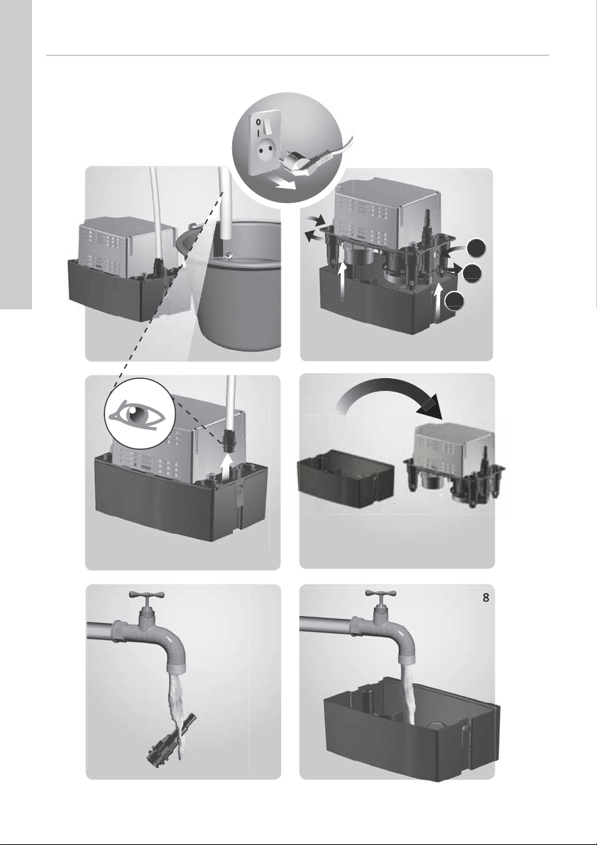
4.1 Checking the alarm
1. To ensure that the alarm level is reached,
squeeze the outlet hose or close the isolating
valve, if fitted, and fill water into the tank. The
pump will be started via the float switch.
2. Continue filling water into the tank until the safety
overflow switch is activated. If no external alarm
is connected to the Conlift, this function can be
checked by means of a multimeter.
TM05 1152 2211
3. Stop filling water into the tank and stop
After checking the alarm, push the inlet hose into the
lifting station and let the condensate from the boiler
or air-conditioning system run into the tank again.
The safety overflow switch must be
activated before the water starts running
out of Conlift.
squeezing the outlet hose. The alarm stops (the
switch opens). The pump continues operating.
When the stop level is reached, the pump stops.
4
Page 5
5. Product introduction
5.4 Handling of condensates
5.1 Product description
Grundfos Conlift1 LS is a small, compact lifting
station with built-in-non-return valve.
5.2 Intended use
The Conlift is designed for the pumping of
condensate from the following:
• boilers
• air-conditioning systems
• cooling and refrigeration systems
• air dehumidifiers
• evaporators.
The Conlift is suitable for the pumping of condensate
which is collected below sewer level or which cannot
flow to the sewage system or drain of the building by
means of a natural downward slope.
WARNING
Biological hazard
Death or serious personal injury
- Use the product only to pump
condensates.
The Conlift can pump condensates not requiring
neutralisation, i.e. with pH values of 2.5 or higher.
Condensates with pH values up to 2.5 must be
neutralised before they leave the Conlift.
Boilers fired with the following fuels normally supply
condensate with pH values up to 2.5:
• gas
• liquid gas
• low-sulphur fuel oil according to DIN 51603-1.
Irrespective of the capability of the Conlift, local
regulations may require the installation of a
neutralisation unit, even for pH values of 2.5 or
higher.
5.3 Operating mode
The Conlift is designed for maximum 60 starts per
hour.
S3 (intermittent operation): 30 % according to DIN
EN 0530 T1. This means that the system is running
for 18 seconds and is stopped for 42 seconds.
If Conlift is to be connected to a
pressure-reducing valve, observe the
boiler manufacturer's instructions.
When cleaning heat exchangers and
burner units of boiler systems, make sure
that no acid and cleaning residuals enter
the condensing unit.
Condensates from condensate boilers are very
aggressive and will attack the material of the
building's sewage system.
In order to protect the sewage system, we
recommend that you use a neutralisation unit. The
neutralisation unit is included in Conlift2 pH+ and is
available as an accessory for Conlift1 and Conlift2.
See section 9. Technical data.
The local outlet regulations regarding condensates
from boilers must be met.
5.5 Marking and approvals
Marking
Approvals
English (GB)
5
Page 6

5.6 Accessories
English (GB)
The following accessories are available from your
local Grundfos supplier.
Accessory/
service part
pH+ Box Complete
Extension
hose
Granulate
refill package
Alarm PCB
Conlift
Description
neutralisation unit
including fitting
accessories,
neutralisation
granulate and pH
indicator.
6 metres of PVC hose
with 10 mm internal
diameter including
one hose coupling.
Granulate, 4 x 1.4 kg. 97936178
Printed-circuit board
(PCB) enabling
additional pump start
at alarm level or stop
of boiler with acoustic
alarm.
6. Control functions
The condensate runs by natural fall through a hose
into the tank. See section 7. Servicing the product.
The liquid level in the tank is controlled automatically
by a float switch. A micro switch in the float switch
will start the pump when the liquid level reaches the
start level, and it will stop the pump again when the
liquid level has fallen to the stop level. The
condensate is pumped through the outlet hose to the
drain.
The Conlift also has a safety overflow switch with a
1.7-metre electric cable. This overflow switch can be
connected to the condensate boiler and set to stop
the boiler in case of an alarm.
The Conlift has a thermal switch which stops the
motor in case of overload. When the motor has
cooled to normal temperature, it restarts
automatically.
Product
number
97936176
97936177
97936209
7. Servicing the product
Always use original accessories from Grundfos to
ensure safe and reliable operation.
WARNING
Electric shock
Death or serious personal injury
- Before starting any work on the product,
make sure that the power supply has
been switched off and that it cannot be
accidentally switched on.
Maintenance and service must be carried
out by specially trained persons and
according to local regulations.
7.1 Maintenance
If the power supply cable is damaged, it
must be replaced by the manufacturer, the
manufacturer's service partner or similarly
qualified person.
The Conlift does not require any special
maintenance, but we recommend that you check
operation and pipe connections at least once a year
and that you clean the collecting tank, if necessary.
7.2 Service
Thanks to the Conlift design, service can easily be
performed in case of malfunction or blocked pump.
Electrical connection must be carried out
by an authorized electrician.
WARNING
Electric shock
Death or serious personal injury
- Before starting any work on the product,
make sure that the power supply has
been switched off and that it cannot be
accidentally switched on.
6
Page 7

7.2.1 Conlift
See illustrations on page 10.
Make the following checks and clean the collecting
tank, if necessary:
1. Disconnect the power supply.
2. Cut off the flow of condensate from the boiler or
other application, or stop the flow of condensate
to the Conlift.
3. Make sure that the hoses are not mechanically or
chemically damaged.
4. Remove the outlet hose by turning the bayonet
coupling, and check the O-ring. The condensate
in the hose will not run out due to the non-return
valve.
5. If the condensate is running out of the hose,
check and clean the non-return valve.
6. Press the side-locking catches and lift off the
motor support. Place it in upright position.
7. Remove deposits, dirt, algae and incrustations
under running water.
7.3 Contaminated products
If a Conlift has been used for a liquid which is
injurious to health or toxic, it will be classified as
contaminated.
CAUTION
Biological hazard
Minor or moderate personal injury
- Flush the product thoroughly with clean
water and rinse the parts in water after
dismantling.
The product will be classified as contaminated if it
has been used for a liquid which is injurious to health
or toxic.
If you request Grundfos to service the product,
contact Grundfos with details about the liquid before
returning the product for service. Otherwise,
Grundfos can refuse to accept the product for
service.
Any application for service must include details
about the liquid.
Clean the product in the best possible way before
you return it.
Costs of returning the product are to be paid by the
customer.
English (GB)
7
Page 8
8. Fault finding the product
English (GB)
WARNING
Electric shock
Death or serious personal injury
- Before starting any work on the product,
make sure that the power supply has
been switched off and that it cannot be
accidentally switched on.
Fault Cause Remedy
1. The pump does
not run.
2. Reduced or no
performance.
3. Frequent
starts/stops.
4. Alarm. a) The condensate is not pumped
a) No power supply. Connect the power supply.
b) A fuse is blown. Replace the fuse (1 A slow-blow fuse).
c) The power supply cable is
damaged.
d) The thermal overload switch
has tripped:
– The motor is not sufficiently
cooled.
– Deposits in the pump. Clean the impeller, pump housing and the
a) Outlet hose squeezed or
broken.
b) The non-return valve does not
open.
c) The motor fan cannot be turned
freely.
a) The non-return valve does not
close.
b) The inlet quantity is too high. Make sure the inlet quantity is correct.
out of the tank.
Repair or replace the cable. This must only
be carried out by an authorised service
workshop or by Grundfos.
Clean the cooling slots in the motor cover.
entire lifting station.
Straighten the outlet hose or replace it. The
bending radius of the hose must be at least
60 mm.
Remove the outlet connection, and clean the
non-return valve.
Clean the pump housing and the impeller.
Remove the outlet connection, and clean the
non-return valve.
See points 1 and 2.
8
Page 9

9. Technical data
Supply voltage
1 x 230 VAC - 6 %/+ 6 %, 50 Hz, PE.
See the nameplate.
Input power
P1 = 70 W.
Input current
I = 0.65 A.
Alarm connection
An external alarm can be connected via the safety
overflow switch.
The cable can stand a control voltage of 250 VAC,
2.5 A.
Cable lengths
Power supply cable: 2.0 metres.
Alarm cable: 1.7 metres.
Storage temperature
When stored in dry rooms:
• Empty tank: -10 - +50 °C.
• Tank with condensate: above 0 °C (risk of frost
not allowed).
Ambient temperature
During operation: 5-35 °C.
Liquid temperature
Average temperature: 50 °C.
Maximum head
5.5 metres.
Maximum flow rate
600 l/h.
pH value of condensate
2.5 or higher.
Density of condensate
Maximum 1000 kg/m
Motor protection
• Thermal overload switch: 120 °C.
• Insulation class: F.
Enclosure class
IP20.
Weight
2.0 kg.
Volume
• Tank volume: 2.65 litres.
• Useful volume: 0.9 litre.
• Alarm condition: 2.1 litres.
• Operating condition: 1.7 litres.
Dimensions
See dimensional sketches on page 11.
3
.
10. Disposal
This product or parts of it must be disposed of in an
environmentally sound way:
1. Use the public or private waste collection service.
2. If this is not possible, contact the nearest
Grundfos company or service workshop.
English (GB)
9
Page 10
Appendix 1
2
3
1
2
3-4 7
8
6
1
88
5
Appendix
Conlift1 LS
.
10
TM05 8628 2413
Page 11

Dimensions, Conlift1 LS
Appendix
TM05 1227 2411
11
Page 12

Grundfos companies
Argentina
Bombas GRUNDFOS de Argentina S.A.
Ruta Panamericana km. 37.500 Centro
Industrial Garin
1619 Garín Pcia. de B.A.
Phone: +54-3327 414 444
Telefax: +54-3327 45 3190
Australia
GRUNDFOS Pumps Pty. Ltd.
P.O. Box 2040
Regency Park
South Australia 5942
Phone: +61-8-8461-4611
Telefax: +61-8-8340 0155
Austria
GRUNDFOS Pumpen Vertrieb
Ges.m.b.H.
Grundfosstraße 2
A-5082 Grödig/Salzburg
Tel.: +43-6246-883-0
Telefax: +43-6246-883-30
Belgium
N.V. GRUNDFOS Bellux S.A.
Boomsesteenweg 81-83
B-2630 Aartselaar
Tél.: +32-3-870 7300
Télécopie: +32-3-870 7301
Belarus
Представительство ГРУНДФОС в
Минске
220125, Минск
ул. Шафарнянская, 11, оф. 56, БЦ
«Порт»
Тел.: +7 (375 17) 286 39 72/73
Факс: +7 (375 17) 286 39 71
E-mail: minsk@grundfos.com
Bosnia and Herzegovina
GRUNDFOS Sarajevo
Zmaja od Bosne 7-7A,
BH-71000 Sarajevo
Phone: +387 33 592 480
Telefax: +387 33 590 465
www.ba.grundfos.com
e-mail: grundfos@bih.net.ba
Brazil
BOMBAS GRUNDFOS DO BRASIL
Av. Humberto de Alencar Castelo
Branco, 630
CEP 09850 - 300
São Bernardo do Campo - SP
Phone: +55-11 4393 5533
Telefax: +55-11 4343 5015
Bulgaria
Grundfos Bulgaria EOOD
Slatina District
Iztochna Tangenta street no. 100
BG - 1592 Sofia
Tel. +359 2 49 22 200
Fax. +359 2 49 22 201
email: bulgaria@grundfos.bg
Canada
GRUNDFOS Canada Inc.
2941 Brighton Road
Oakville, Ontario
L6H 6C9
Phone: +1-905 829 9533
Telefax: +1-905 829 9512
China
GRUNDFOS Pumps (Shanghai) Co. Ltd.
10F The Hub, No. 33 Suhong Road
Minhang District
Shanghai 201106
PRC
Phone: +86 21 612 252 22
Telefax: +86 21 612 253 33
COLOMBIA
GRUNDFOS Colombia S.A.S.
Km 1.5 vía Siberia-Cota Conj. Potrero
Chico,
Parque Empresarial Arcos de Cota Bod.
1A.
Cota, Cundinamarca
Phone: +57(1)-2913444
Telefax: +57(1)-8764586
Croatia
GRUNDFOS CROATIA d.o.o.
Buzinski prilaz 38, Buzin
HR-10010 Zagreb
Phone: +385 1 6595 400
Telefax: +385 1 6595 499
www.hr.grundfos.com
GRUNDFOS Sales Czechia and
Slovakia s.r.o.
Čajkovského 21
779 00 Olomouc
Phone: +420-585-716 111
Denmark
GRUNDFOS DK A/S
Martin Bachs Vej 3
DK-8850 Bjerringbro
Tlf.: +45-87 50 50 50
Telefax: +45-87 50 51 51
E-mail: info_GDK@grundfos.com
www.grundfos.com/DK
Estonia
GRUNDFOS Pumps Eesti OÜ
Peterburi tee 92G
11415 Tallinn
Tel: + 372 606 1690
Fax: + 372 606 1691
Finland
OY GRUNDFOS Pumput AB
Trukkikuja 1
FI-01360 Vantaa
Phone: +358-(0) 207 889 500
France
Pompes GRUNDFOS Distribution S.A.
Parc d’Activités de Chesnes
57, rue de Malacombe
F-38290 St. Quentin Fallavier (Lyon)
Tél.: +33-4 74 82 15 15
Télécopie: +33-4 74 94 10 51
Germany
GRUNDFOS GMBH
Schlüterstr. 33
40699 Erkrath
Tel.: +49-(0) 211 929 69-0
Telefax: +49-(0) 211 929 69-3799
e-mail: infoservice@grundfos.de
Service in Deutschland:
e-mail: kundendienst@grundfos.de
Greece
GRUNDFOS Hellas A.E.B.E.
20th km. Athinon-Markopoulou Av.
P.O. Box 71
GR-19002 Peania
Phone: +0030-210-66 83 400
Telefax: +0030-210-66 46 273
Hong Kong
GRUNDFOS Pumps (Hong Kong) Ltd.
Unit 1, Ground floor
Siu Wai Industrial Centre
29-33 Wing Hong Street &
68 King Lam Street, Cheung Sha Wan
Kowloon
Phone: +852-27861706 / 27861741
Telefax: +852-27858664
Hungary
GRUNDFOS Hungária Kft.
Park u. 8
H-2045 Törökbálint,
Phone: +36-23 511 110
Telefax: +36-23 511 111
India
GRUNDFOS Pumps India Private
Limited
118 Old Mahabalipuram Road
Thoraipakkam
Chennai 600 096
Phone: +91-44 2496 6800
Indonesia
PT. GRUNDFOS POMPA
Graha Intirub Lt. 2 & 3
Jln. Cililitan Besar No.454. Makasar,
Jakarta Timur
ID-Jakarta 13650
Phone: +62 21-469-51900
Telefax: +62 21-460 6910 / 460 6901
Ireland
GRUNDFOS (Ireland) Ltd.
Unit A, Merrywell Business Park
Ballymount Road Lower
Dublin 12
Phone: +353-1-4089 800
Telefax: +353-1-4089 830
Italy
GRUNDFOS Pompe Italia S.r.l.
Via Gran Sasso 4
I-20060 Truccazzano (Milano)
Tel.: +39-02-95838112
Telefax: +39-02-95309290 / 95838461
Japan
GRUNDFOS Pumps K.K.
1-2-3, Shin-Miyakoda, Kita-ku,
Hamamatsu
431-2103 Japan
Phone: +81 53 428 4760
Telefax: +81 53 428 5005
Korea
GRUNDFOS Pumps Korea Ltd.
6th Floor, Aju Building 679-5
Yeoksam-dong, Kangnam-ku, 135-916
Seoul, Korea
Phone: +82-2-5317 600
Telefax: +82-2-5633 725
Latvia
SIA GRUNDFOS Pumps Latvia
Deglava biznesa centrs
Augusta Deglava ielā 60, LV-1035, Rīga,
Tālr.: + 371 714 9640, 7 149 641
Fakss: + 371 914 9646
Lithuania
GRUNDFOS Pumps UAB
Smolensko g. 6
LT-03201 Vilnius
Tel: + 370 52 395 430
Fax: + 370 52 395 431
Page 13

Malaysia
GRUNDFOS Pumps Sdn. Bhd.
7 Jalan Peguam U1/25
Glenmarie Industrial Park
40150 Shah Alam
Selangor
Phone: +60-3-5569 2922
Telefax: +60-3-5569 2866
Mexico
Bombas GRUNDFOS de México S.A. de
C.V.
Boulevard TLC No. 15
Parque Industrial Stiva Aeropuerto
Apodaca, N.L. 66600
Phone: +52-81-8144 4000
Telefax: +52-81-8144 4010
Netherlands
GRUNDFOS Netherlands
Veluwezoom 35
1326 AE Almere
Postbus 22015
1302 CA ALMERE
Tel.: +31-88-478 6336
Telefax: +31-88-478 6332
E-mail: info_gnl@grundfos.com
New Zealand
GRUNDFOS Pumps NZ Ltd.
17 Beatrice Tinsley Crescent
North Harbour Industrial Estate
Albany, Auckland
Phone: +64-9-415 3240
Telefax: +64-9-415 3250
Norway
GRUNDFOS Pumper A/S
Strømsveien 344
Postboks 235, Leirdal
N-1011 Oslo
Tlf.: +47-22 90 47 00
Telefax: +47-22 32 21 50
Poland
GRUNDFOS Pompy Sp. z o.o.
ul. Klonowa 23
Baranowo k. Poznania
PL-62-081 Przeźmierowo
Tel: (+48-61) 650 13 00
Fax: (+48-61) 650 13 50
Portugal
Bombas GRUNDFOS Portugal, S.A.
Rua Calvet de Magalhães, 241
Apartado 1079
P-2770-153 Paço de Arcos
Tel.: +351-21-440 76 00
Telefax: +351-21-440 76 90
Romania
GRUNDFOS Pompe România SRL
Bd. Biruintei, nr 103
Pantelimon county Ilfov
Phone: +40 21 200 4100
Telefax: +40 21 200 4101
E-mail: romania@grundfos.ro
Russia
ООО Грундф ос Россия
ул. Школьная, 39-41
Москва, RU-109544, Russia
Тел. (+7) 495 564-88-00 (495)
737-30-00
Факс (+7) 495 564 8811
E-mail grundfos.moscow@grundfos.com
Serbia
Grundfos Srbija d.o.o.
Omladinskih brigada 90b
11070 Novi Beograd
Phone: +381 11 2258 740
Telefax: +381 11 2281 769
www.rs.grundfos.com
Singapore
GRUNDFOS (Singapore) Pte. Ltd.
25 Jalan Tukang
Singapore 619264
Phone: +65-6681 9688
Telefax: +65-6681 9689
Slovakia
GRUNDFOS s.r.o.
Prievozská 4D
821 09 BRATISLAVA
Phona: +421 2 5020 1426
sk.grundfos.com
Slovenia
GRUNDFOS LJUBLJANA, d.o.o.
Leskoškova 9e, 1122 Ljubljana
Phone: +386 (0) 1 568 06 10
Telefax: +386 (0)1 568 06 19
E-mail: tehnika-si@grundfos.com
South Africa
GRUNDFOS (PTY) LTD
Corner Mountjoy and George Allen
Roads
Wilbart Ext. 2
Bedfordview 2008
Phone: (+27) 11 579 4800
Fax: (+27) 11 455 6066
E-mail: lsmart@grundfos.com
Spain
Bombas GRUNDFOS España S.A.
Camino de la Fuentecilla, s/n
E-28110 Algete (Madrid)
Tel.: +34-91-848 8800
Telefax: +34-91-628 0465
Sweden
GRUNDFOS AB
Box 333 (Lunnagårdsgatan 6)
431 24 Mölndal
Tel.: +46 31 332 23 000
Telefax: +46 31 331 94 60
Switzerland
GRUNDFOS Pumpen AG
Bruggacherstrasse 10
CH-8117 Fällanden/ZH
Tel.: +41-44-806 8111
Telefax: +41-44-806 8115
Tai wan
GRUNDFOS Pumps (Taiwan) Ltd.
7 Floor, 219 Min-Chuan Road
Taichung, Taiwan, R.O.C.
Phone: +886-4-2305 0868
Telefax: +886-4-2305 0878
Thailand
GRUNDFOS (Thailand) Ltd.
92 Chaloem Phrakiat Rama 9 Road,
Dokmai, Pravej, Bangkok 10250
Phone: +66-2-725 8999
Telefax: +66-2-725 8998
Turkey
GRUNDFOS POMPA San. ve Tic. Ltd.
Sti.
Gebze Organize Sanayi Bölgesi
Ihsan dede Caddesi,
2. yol 200. Sokak No. 204
41490 Gebze/ Kocaeli
Phone: +90 - 262-679 7979
Telefax: +90 - 262-679 7905
E-mail: satis@grundfos.com
Ukraine
Бізнес Центр Європа
Столичне шосе, 103
м. Київ, 03131, Україна
Телефон : (+38 044) 237 04 00
Факс.: (+38 044) 237 04 01
E-mail: ukraine@grundfos.com
United Arab Emirates
GRUNDFOS Gulf Distribution
P.O. Box 16768
Jebel Ali Free Zone
Dubai
Phone: +971 4 8815 166
Telefax: +971 4 8815 136
United Kingdom
GRUNDFOS Pumps Ltd.
Grovebury Road
Leighton Buzzard/Beds. LU7 4TL
Phone: +44-1525-850000
Telefax: +44-1525-850011
U.S.A.
GRUNDFOS Pumps Corporation
17100 West 118th Terrace
Olathe, Kansas 66061
Phone: +1-913-227-3400
Telefax: +1-913-227-3500
Uzbekistan
Grundfos Tashkent, Uzbekistan The
Representative Office of Grundfos
Kazakhstan in Uzbekistan
38a, Oybek street, Tashkent
Телефон: (+998) 71 150 3290 / 71 150
3291
Факс: (+998) 71 150 3292
Addresses Revised 09.08.2017
Grundfos companies
Page 14

98491876 1117
ECM: 1222640
www.grundfos.com
© Copyright Grundfos Holding A/S
owned by Grundfos Holding A/S or Grundfos A/ S, Denmark. All rights reserved worldwide.
The name Grundfos, the Grundfos logo, and be think innovate are registered trademarks
 Loading...