

Page 1
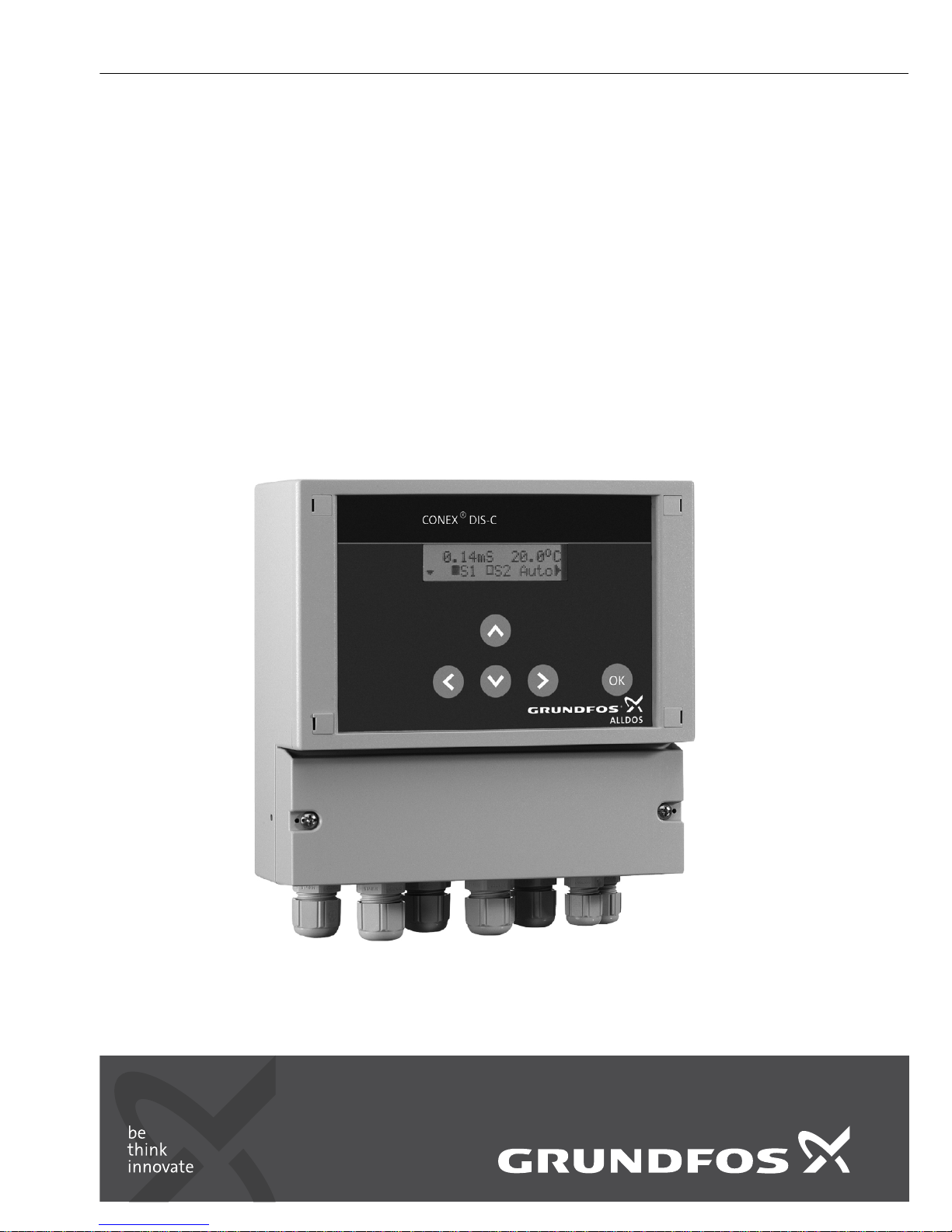
Conex® DIS-C
Installation and operating instructions
GRUNDFOS INSTRUCTIONS
Page 2
English (GB)
2
English (GB) Installation and operating instructions
Original installation and operating instructions
CONTENTS
Page
1. Symbols used in this document
2. General information
These installation and operating instructions contain
all information important for users of the
Conex
®
DIS-C:
• technical data
• instructions on commissioning, use and
maintenance
• safety information.
Should you require further information or should you
encounter problems that are not handled in sufficient
depth in this manual, please contact Grundfos.
We shall be pleased to support you with our
comprehensive know-how in the fields of measuring
and control technology as well as water treatment.
We always welcome suggestions on how to optimise
our installation and operating instructions to satisfy
our customers.
1. Symbols used in this document
2
2. General information
2
3. Description of the device
3
3.1 Assembly
3
3.2 Principles of conductivity measurement
3
4. Applications
4
4.1 Field of application for measurements
4
5. Safety
4
5.1 Obligations of the owner/operations
manager
4
5.2 Avoidance of danger
4
6. Identification
5
6.1 Nameplate
5
6.2 Type key
5
7. Technical data
6
7.1 Versions
6
7.2 General data
6
7.3 Measuring ranges
6
7.4 Dimensional sketches / drilling diagram
7
8. Installation
8
8.1 Transport and storage
8
8.2 Unpacking
8
8.3 Installation requirements
8
8.4 Assembling the Conex® DIS-C housing
for wall mounting
8
8.5 Assembling the Conex® DIS-C-P, CI
housing for installation in control panel
9
9. Commissioning / electrical
connections
9
9.1 Conex® DIS-C conductive, housing for
wall mounting
10
9.2 Conex® DIS-C inductive, housing for
wall mounting
11
9.3 Conex® DIS-C conductive, housing for
installation in control panel
12
9.4 Important instructions for connecting the
device
13
10. Principles of regulatory function
14
10.1 Regulatory behaviour
14
10.2 Limit values
14
10.3 On-off controller with P behaviour
15
10.4 Parameter settings
16
11. Initial operation and settings
17
11.1 Initial steps for operation
17
12. Operation
17
12.1 Device layout for Conex® DIS-C
17
12.2 Menu control
18
12.3 Navigation in the menus
18
12.4 Setup
19
12.5 Relay menu (S1 S2)
23
12.6 Temperature compensation
23
12.7 Displaying / changing code
24
12.8 Controller settings
24
12.9 Alarm value setting A1/A2
25
12.10 Service
26
13. Disposal
26
Warning
Prior to installation, read these installation
and operating instructions. Installation and
operation must comply with local
regulations and accepted codes of good
practice.
Warning
If these safety instructions are not
observed, it may result in personal injury.
Caution
If these safety instructions are not
observed, it may result in malfunction or
damage to the equipment.
Note
Notes or instructions that make the job
easier and ensure safe operation.
Page 3

English (GB)
3
3. Description of the device
Fig. 1 Conex® DIS-C for wall mounting
Fig. 2 Conex
®
DIS-C for installation in control
panel
3.1 Assembly
The complete measuring system comprises:
• the measuring amplifier Conex
®
DIS-C
• the conductivity measuring cell with temperature
sensor.
3.2 Principles of conductivity
measurement
In metallic conductors, electricity is transported by
freely moving electrons, whereas in electrolytes, the
electrical current is carried by ions.
All water-dissolved components that are in ionogenic
form contribute towards conductivity.
The conductivity is a sum parameter.
Different types of ions vary in their electrical charge
and migration rate. The migration rate is highly
dependent on temperature, which means the
influence of temperature must always be taken into
account when measuring conductivity.
Specific electrolytic conductivity is measured in
Siemens per cm (S/cm). Siemens per cm is the
reciprocal value of electrical resistance.
This measurement is based on a theoretical liquid
cube with sides of a length of 1 cm. In practice, cells
rarely have such an even geometric shape. The cell
constant C is used to specify the correlation between
the actual measured conductivity and the displayed
specific conductivity.
The measuring cell is inserted in a flow armature,
and the water to be measured flows around it.
The Conex
®
DIS-C measuring and regulation device
amplifies the signal from the measuring cell and
calculates the signal (e.g. against cable and
temperature compensation parameters). The result
is displayed digitally and can also be registered
using the analog output. The result is shown as an
actual value.
TM03 6980 3914TM03 6981 4506
Page 4

English (GB)
4
4. Applications
The Conex® DIS-C is a measuring amplifier for
measuring conductivity using a conductive or
inductive measuring cell and for regulation of
disturbance variables using a connected control
element. Two controllers can be set separately as
limit values, intermittent pulse controllers or pulse
frequency controllers.
The Conex
®
DIS-C is available for installation in a
wall-mounted enclosure or for installation in a control
panel (only conductive measuring cell for
conductivity measurement).
4.1 Field of application for measurements
Principal uses:
• waste water treatment
• water purification
• recycling
• in metal processing industries
• in the chemical industry
• in the foodstuff industry.
5. Safety
The owner/operations manager of the system is
responsible for the following:
• compliance with country-specific safety
regulations
• training of operating personnel.
5.1 Obligations of the owner/operations
manager
The owner/operations manager must ensure that
persons working with the device described fulfil
these requirements:
• They are acquainted with the regulations
concerning working safety and accident
prevention.
• They have been trained in use of the device.
• They have read and understood the warning
information and handling symbols.
The owner/operations manager is also responsible
for ensuring that this manual is kept in the immediate
vicinity of the device and is always available for the
operating personnel.
5.2 Avoidance of danger
Warning
Installation and connection of the device
and the associated supplementary
components must only be carried out by
authorised personnel!
The local safety regulations must be
observed!
Switch off the power supply before
connecting the power cable and the relay
contacts!
Warning
Do not dismantle the device!
Cleaning, maintenance and repair must
only be carried out by authorised
personnel!
Warning
Other applications than those described in
section 4. Applications are not approved
and not permitted. Grundfos cannot be
held liable for any damage resulting from
incorrect use.
Caution
The mounting location must be selected so
that the housing is not subjected to
mechanical loading.
Check that all settings are correct before
starting up the device!
Page 5
English (GB)
5
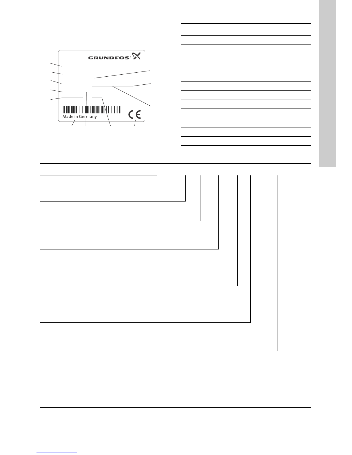
6. Identification
6.1 Nameplate
Fig. 3 Nameplate, Conex® DIS-C
6.2 Type key
TM04 0331 3914
DIS-C 1-CC, W-G
351-2000-10006
S/N: 08/02809
Conex DIS-C, 230/240V 50/60Hz
10 VA, IP 65
96725733P1108030802809
1
2
3
4
5
67 8 9
10
11
12
Pos. D escription
1 Type designation
2 Model
3 Product name
4 Power consumption [VA]
5 Product number
6 Country of origin
7 Enclosure class
8 Year and week of production
9 Marks of approval, CE mark, etc.
10 Voltage [V]
11 Frequency [Hz]
12 Serial number
Example: DIS -C -P CC -R1 -F -PVC W -G
Units for measurement and control
DIS-C
Dosing Instrumentation Standard for
conductivity measurement
Assembly
PPrepacked
Measuring cell
CC Conductivity, conductive
CI Conductivity, inductive
Measuring range
R1 0 to 200 μS/cm
R2 0 to 2000 μS/cm
R3 0 to 20,000 μS/cm
Armature type
FFlow
I Immersion
X No armature
Armature material
PVC Polyvinyl chloride
PP Polypropylene
Controller mounting option
W Wall-mounted
P Panel-mounted (only for conductive measuring cell)
Power supply
G 1 x 230/240 V, 50/60 Hz
H 1 x 115/120 V, 50/60 Hz
Page 6

English (GB)
6
7. Technical data
7.1 Versions
7.2 General data
7.3 Measuring ranges
7.3.1 Measuring ranges and cell constants for
Conex
®
DIS-C with conductive measuring
cell
7.3.2 Measuring ranges for Conex
®
DIS-C with
inductive measuring cell
Power supply
• 230 V (± 10 %), 50/60 Hz
(standard version)
• 115/120 V (± 10 %),
50/60 Hz
Type of measuring
cell
• Conductive
• Inductive
Mounting variants
• For wall mounting
• For installation in control
panel (only Conex
®
DIS-C,
CI devices - with
conductive measuring cell).
Dimensions
(W x H x D)
• 165 x 160 x 80 mm
(for wall mounting)
• 96 x 96 x 127 mm (for
installation in control panel)
Weight
• 1.0 kg (for wall mounting)
• 0.8 kg (for installation in
control panel)
Enclosure class
• IP65 (wall-mounted)
• IP54 (front, installation in
control panel)
Internal fuse
• Yes (wall-mounted)
• No (installation in control
panel)
Display
LCD display, two lines,
2 x 16 characters
Connections
Terminal strips for cable up to
maximum 1.5 mm
2
Power consumption 10 VA
Electrical output
0 (4) to 20 mA galvanically
isolated, maximum load 500 Ω
Switching points
Can be set within the
measuring range
Contact rating for
regulation and alarm
relay
6 A / 250 V, maximum ohm
resistive load 550 VA
(with RC contact protection)
Permissible ambient
temperature
0 °C to +50 °C
Permissible storage
temperature
-20 °C to +65 °C
Maximum relative
humidity
90 % (non-condensing)
Adjustable
temperature
coefficient of
measurement
solution
0 to 8 % / °C
Proportional band Xp 1 to 3000 %
Reset time Tn 0 to 3000 seconds
Measuring range Cell constant
Conductive
measuring
cell
0 to 20 MΩ/cm
C = 0.05 96609150
0 to 2 μS/cm
0 to 20 μS/cm
0 to 200 μS/cm
0 to 2 mS/cm C = 0.2 96609151
0 to 20 mS/cm C = 1 96609152
Measuring range
Inductive measuring
cell
0 to 2.000 mS/cm
95720194
0 to 20.00 mS/cm
0 to 200.0 mS/cm
0 to 2000 mS/cm
Page 7
English (GB)
7
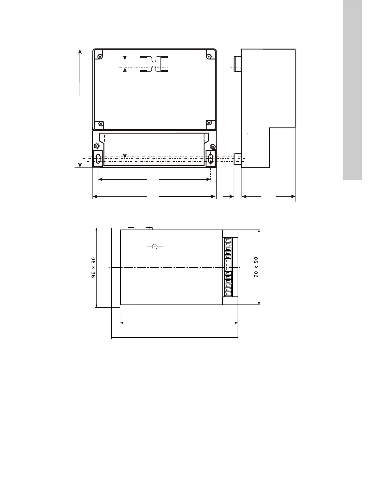
7.4 Dimensional sketches / drilling diagram
Fig. 4 Dimensional sketch / drilling diagram for Conex® DIS-C for wall mounting
Fig. 5 Dimensional sketch / mounting sketch for Conex
®
DIS-C for control-panel wall mounting
TM03 6982 4506TM03 6983 4506
10
72.5
1
6
0
165
151
1
2
0
1
5
approx. 129
approx. 137
Page 8

English (GB)
8
8. Installation
8.1 Transport and storage
• Transport the device carefully, do not drop!
• Store at dry and cool location between -20 °C
and +65 °C.
8.2 Unpacking
• Check the device for damage. Install as soon as
possible after unpacking.
• Do not install or connect damaged devices!
8.3 Installation requirements
• The location must be vibration-free, dry, dust-free
and free of corrosive, pungent fumes or
aggressive solvents.
• Observe the data in section 7. Technical data.
8.4 Assembli ng the C one x® DIS-C housing
for wall mounting
Fig. 6 Installation of Conex® DIS-C for wall mounting
1. Drill three dowel holes with a diameter of 8 mm.
See section 7.4 Dimensional sketches / drilling
diagram.
2. Insert the supplied dowel pins.
3. Unscrew the clamp cover from the device.
4. Screw in the top middle screw.
5. Hang the device onto this screw.
6. Secure the device using the other two screws.
7. Screw the clamp cover back on.
Caution
Do not allow any foreign bodies to enter!
Note
Retain the packing material or dispose of it
according to local regulations.
Caution
If you do not observe the installation
requirements, the device may be
damaged! The measurements may not be
correct!
Warning
Switch off the power supply before
installing!
Enclosure class IP65 is only guaranteed if
the clamp covers and the associated
threaded cable connections and temporary
covers are closed.
TM03 6985 4506
151
120
Caution
Do not damage the gasket.
The gasket must be fitted exactly.
Page 9

English (GB)
9
8.5 Assembling the Conex® DIS-C-P, CI
housing for installation in control panel
1. Make an opening of 92 + 0.8 mm x 92 + 0.8 mm
in the control panel.
2. Slip on the supplied gasket.
3. Insert the device into the opening from the front.
4. Hook the clamps into the tightening cones on the
sides at the top and bottom.
5. Secure the device from the rear using a
screwdriver.
9. Commissioning / electrical
connections
1. Remove the terminal cover on the front of the
device.
2. Use the appropriate cable feedthroughs and
tighten the screws carefully.
3. Connect the cables used to the terminals
according to the Conex
®
DIS-C terminal
assignment.
4. Close the terminal cover again with correctly
positioned gasket.
Caution
Do not damage the gasket.
The gasket must be fitted exactly.
Warning
Switch off the power supply before
installing!
Enclosure class IP65 is only guaranteed
with the front panel of the terminals
enclosure closed and with appropriate
cable glands or dummy caps.
Warning
Switch off the power supply before
connecting the power supply cable and the
relay contacts! For safety reasons, the
protective conductor must be connected
correctly!
Observe the local safety regulations!
Protect the cable connections and plugs
against corrosion and humidity.
Caution
Before connecting the power supply cable,
check that the supply voltage specified on
the nameplate corresponds to the local
conditions!
An incorrect supply voltage may destroy
the device!
To ensure electromagnetic compatibility
(EMC), the input and current output cables
must be screened.
Connect the screening to the screen
ground on one side.
Refer to the wiring diagram! Route the
input, current output and power supply
cables in separate cable channels.
Caution
Enclosure class IP65 is only guaranteed if
the terminal cover is correctly sealed! Do
not damage the gasket on the terminal
cover!
The gasket on the terminal cover must be
positioned precisely!
Do not damage the gasket!
Note
Unused terminals must remain open.
Page 10

English (GB)
10
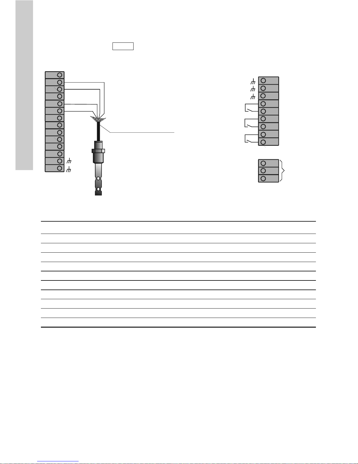
9.1 Conex® DIS-C conductive, housing for wall mounting
Fig. 7 Terminal connection diagram for Conex® DIS-C with conductive measuring cell, housing for wall
mounting
Caution
The measurement input must be screened!
The screen must not be connected to the
Conex
®
DIS-C, but only to the measuring
cell (outer casing of the cell)!
TM03 6986 3914
12
4
5
6
11 12
13
20
21
22
+
L
NPE
14
15 16
17
18 19
A
3
28
27
26
+
29
+
24V
With Pt100, connection with cable:
96611925 (5 m)
96611928 (15 m)
96611929 (25 m)
(maximum cable length: 50 m)
Pos. Description
1 White, inner electrode of measuring cell
2 Brown, outer electrode of measuring cell
4 Yellow, Pt100
5 Green, Pt100
A Trimmer contrast setting
11-12 0/4-20 mA output
14 / 15 Control relay 1 output
16 / 17 Control relay 2 output
18 / 19 Alarm relay 3 output
20 / 21 / 22 For supply voltage, see nameplate
26 / 27 Water sensor
28 Screen
Page 11

English (GB)
11
9.2 Conex® DIS-C inductive, housing for wall mounting
Fig. 8 Terminal connection diagram for Conex® DIS-C with inductive measuring cell, housing for wall
mounting
TM03 6987 4011
12
4
5
61112
13
20
21
22
+
L
N
PE
28
27
26
+
14
15 16
17
18 19
A
29
+
24V
3
3b
Connection with 6 m cable,
extendable with extension cable
95720380
Caution!
Cable length without screen:
maximum 30 mm
Caution!
When extending the cable, the screen
must also be extended!
Pos. Description
1 Green, measurement
2 White, screen
3 Red, voltage supply
3b Black, voltage supply screen
4 Yellow, temperature sensor NTC, screen
5 Brown, temperature sensor NTC
A Trimmer contrast setting
11 / 12 0/4 to 20 mA output
14 / 15 Control relay 1 output
16 / 17 Control relay 2 output
18 / 19 Alarm relay 3 output
20 / 21 / 22 For supply voltage, see nameplate
26 / 27 Water sensor (external controller stop)
28 +24 V
29 Screen
Page 12
English (GB)
12
9.3 Conex® DIS-C conductive, housing for installation in control panel
Fig. 9 Terminal connection diagram for Conex® DIS-C with conductive measuring cell, housing for
installation in control panel
Caution
The screen must not be connected to the
Conex
®
DIS-C, but only to the measuring
cell. See the installation and operating
instructions for the measuring cell!
TM03 6988 4409
L1
N
PE
+
-
+
-
1
24
25
26
3
2
4
5
6
7
8
9
10
11
12
13
14
15
18
21
16
19
22
17
20
23
With Pt100, connection with cable:
96611925 (5 m)
96611928 (15 m)
96611929 (25 m)
(maximum length: 50 m)
Pos. Description
2 White, inner electrode of measuring cell
3 Brown, outer electrode of measuring cell
5 Yellow, Pt100
6 Green, Pt100
9 / 10 0/4 to 20 mA output
11 / 12 Water sensor
18 / 19 Control relay 1 output
20 / 21 Control relay 2 output
22 / 23 Alarm relay 3 output
24 / 25 / 26 For supply voltage, see nameplate
Page 13
English (GB)
13
9.4 Important instructions for connecting
the device
As is common in microprocessor-controlled devices,
certain precautions must be taken during installation
and wiring. In addition to the general guidelines, the
following is of particular importance:
• Input wires and control wires must be laid
separately from one another and from power
supply cables.
• Analog output wires must be screened.
The screen can be connected to the device.
• Relays and protective spools must remain free of
interference.
• If inductive loads are connected, they must either
be screened, or the relay contact must be
protected on the clamping strip of the
Conex
®
DIS-C by an RC protective circuit, in
accordance with the following table and the
switching diagrams.
9.4.1 Power supply
• The device is connected to the power supply at
the clamps (L), (N) and (PE).
• Check the correct supply voltage on the
nameplate.
9.4.2 Connecting the conductivity measuring cell
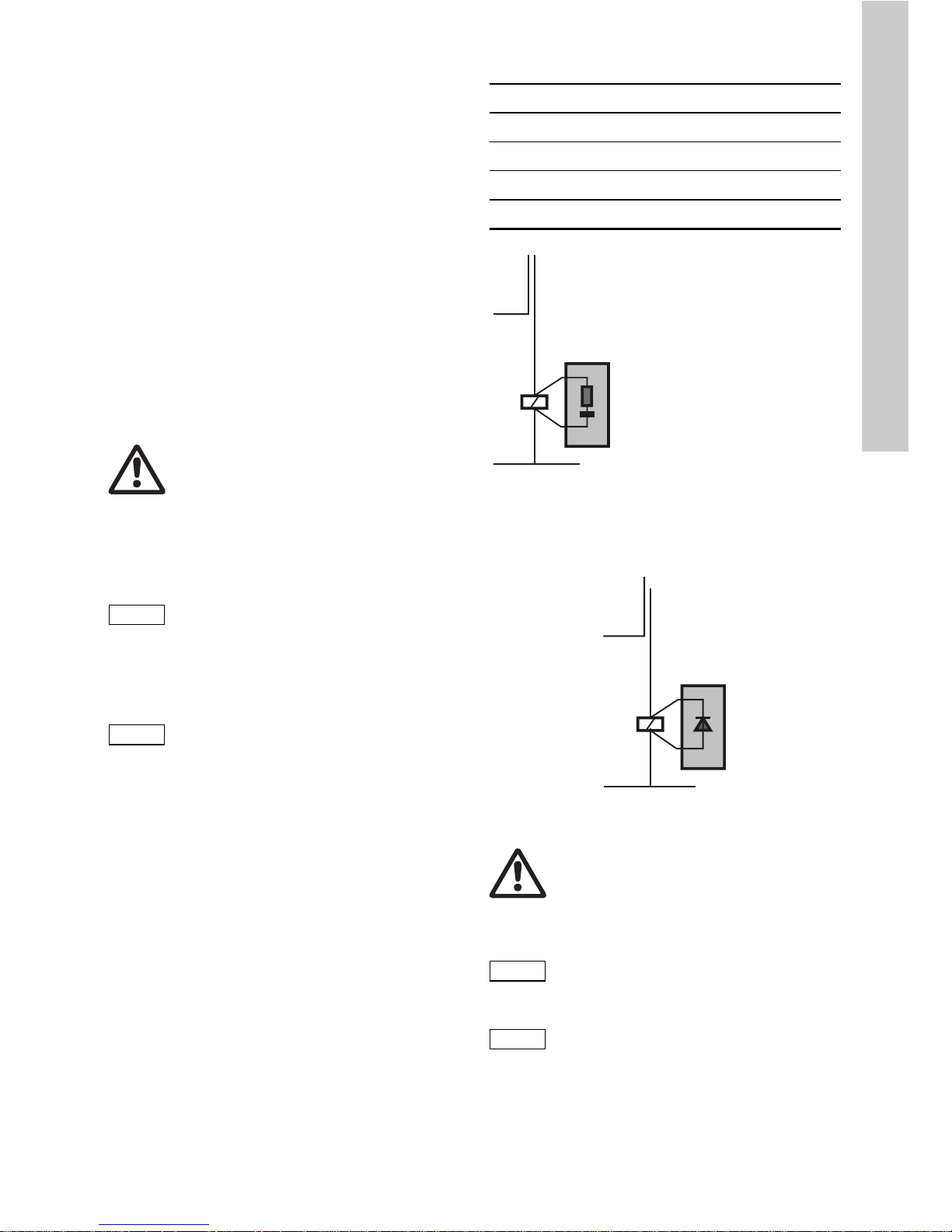
9.4.3 Relay outputs
If inductive loads (including relay and protective spools)
are connected, they must be screened. If this is not
possible, the relay contact must be protected using a
protection circuit in accordance with the table below.
For AC current
Fig. 10 Protection circuit with AC current
For DC voltage
The relay or protective spool must be screened with
a suppressor diode.
Fig. 11 Protection circuit with DC voltage
9.4.4 Current outputs
Warning
Before connecting the device, switch off
the power supply!
Caution
Connection of an incorrect supply voltage
may destroy the device!
Caution
For connecting the conductivity cell to the
Conex
®
DIS-C, only use the prescribed
cable. This cable must not be used in the
same cable channel as power supply
cables!
Protect cable connections and plugs
against corrosion and moisture!
Current up to Capacitor C Resistor R
60 mA 10 nF, 260 V 390 Ω, 2 W
70 mA 47 nF, 260 V 22 Ω, 2 W
150 mA 100 nF, 260 V 47 Ω, 2 W
1.0 A 220 nF, 260 V 47 Ω, 2 W
TM03 6990 4506TM03 7007 4506
Warning
If floating relay outputs are used, they
must be supplied with a backup fuse!
Caution
When connecting the electrical outputs, be
aware of the polarity and the maximum
load (500 Ω)!
Caution
Use a screened cable for connecting the
electrical outputs. The screen must be
connected to PE with one end.
R = 47 to 390 Ω
C = 10 nF to 220 nF / 260 V
e.g. Siemens MKC B 81 921
Values can be found in the
above table.
+
-
Page 14
English (GB)
14
10. Principles of regulatory function
Freely selectable control functions mean that the
Conex
®
DIS-C controller can be adapted to a wide
variety of closed-loop control systems.
10.1 Regulatory behaviour
10.1.1 P regulation behaviour
The P controller has a static characteristic curve.
The characteristic proportional band for the P
controller is Xp. Within this range, which is limited to
a maximum or minimum depending on the control
direction, there is a proportional correlation between
the input and output quantities of the controller.
The lower limit is the response threshold of the
controller. This is the smallest regulatory deviation
that leads to a measurable control variable.
The upper limit separates the proportional band from
saturation. Above this limit, no further increase in
output signal is possible, regardless of increases in
the input signal. This range is called the control
range of the controller, and the control variable can
have any value within this range.
Due to the static characteristic curve, the P controller
cannot reach the setpoint in a stationary state.
This results in a consistent regulatory deviation,
which can be reduced by decreasing Xp, but which
cannot be completely eliminated using a P controller.
The controller reacts quicker with small Xp values.
The Xp value cannot, however, be reduced
arbitrarily, as this causes the controller to become
unstable.
10.1.2 I regulation behaviour
The non-delayed relationship between the regulatory
deviation and the control variable in a P controller
results in an undesirable persistent regulatory
deviation. However, if the regulatory deviation is
controlled directly by the regulating speed instead of
the control variable, this fixed assignment of the two
variables no longer applies. The result is an
integrated controller.
With a regulatory deviation of zero, i.e. when the
setpoint is equal to the actual value, the regulating
speed is also zero. Both positive and negative
regulatory deviations can be influenced by positive
or negative regulating speeds. The control variable
covers the whole control range. The control range of
the I controller is the range in which the regulatory
deviation controls the regulating speed in a linear
fashion.
The characteristic value of the I controller is the reset
time Tn. The reset time is the time that must elapse,
due to the integrated mode of action, for the step
response to reach the value that a P controller would
reach immediately.
The control circuit reacts slowly. If a regulatory
deviation results, an I controller can only react by
constantly changing its control variable. For this
reason, regulation with I controllers is always slower
than with controllers that act proportionally. If the
speed of the controller is increased by decreasing
the integration constant, the control circuit has a
slight tendency towards instability.
At Tn = 0, the controller has no I proportion.
In the absence of external influences, a control
circuit with an I controller therefore has no residual
regulatory deviation in a stationary state when the
control variable is constant.
10.2 Limit values
In principle, the limit value only has two switching
states; ON and OFF. Depending on the set control
direction, the controller is deactivated when the
setpoint value is exceeded, or when the value drops
below the setpoint.
10.2.1 Limit values with hysteresis
To prevent constant switching when the setpoint
value is reached, it is possible to specify a hysteresis
for the controller.
Example:
• setpoint 600 μS/cm
• hysteresis 10 μS/cm.
The hysteresis band is arranged symmetrically
around the switching point.
• Switch-off point = measured value + hysteresis / 2
• Switch-on point = measured value - hysteresis / 2.
Fig. 12 Limit values with hysteresis
Note
Setting for a limit value: Xp = O.
TM03 6991 4506
605
600
595
µS/cm
µS/cm
µS/cm
1
0
Relay
605 μS/cm
600 μS/cm
595 μS/cm
μS/cm
Page 15

English (GB)
15
10.3 On-off controller with P behaviour
It is possible to use an on-off controller with P
behaviour as an intermittent pulse regulator or as a
pulse frequency regulator.
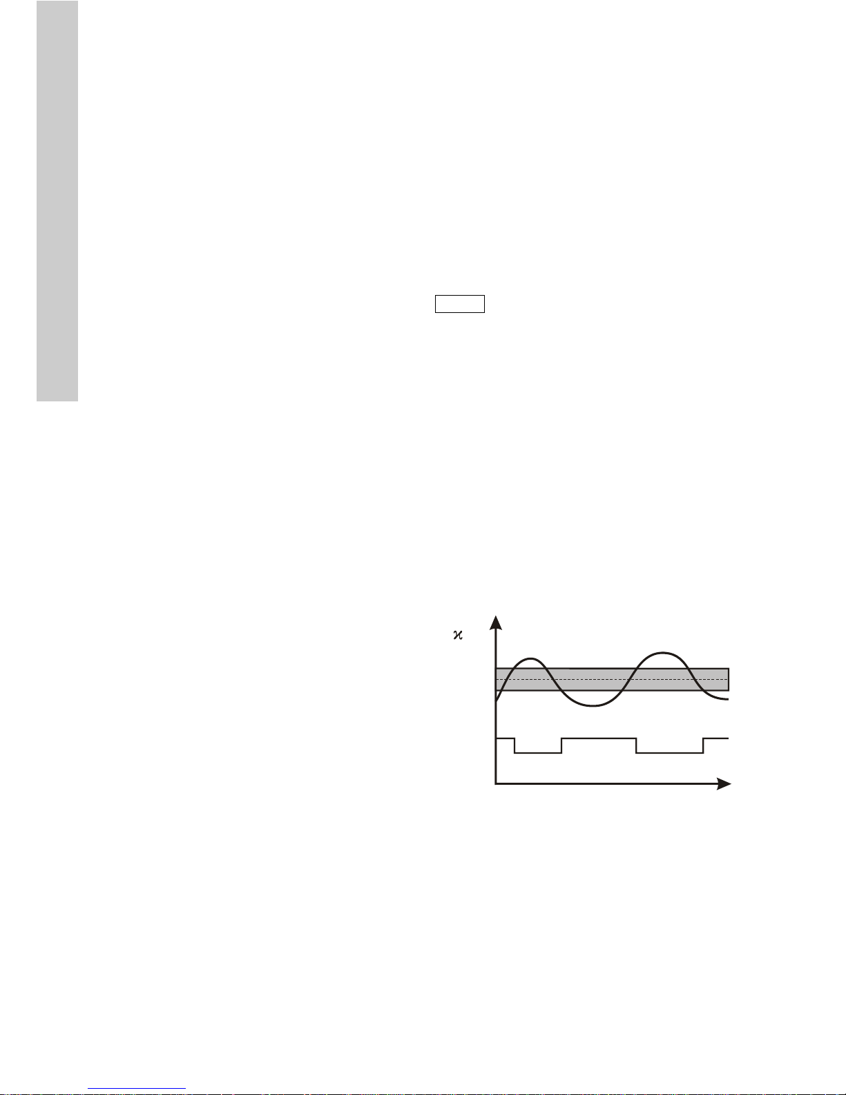
10.3.1 Intermittent pulse regulator
Example:
• setpoint = 6 mS/cm
• measuring range 0 to 10
• Xp = 30
• control direction = downwards.
Xp determines the size of the proportional band as a
percentage of the measuring range. In the following
example, this means that above 6 mS the relay
switches on, first with a short activation time and
then with an increasing activation time to 9 mS (the
total switching on + off time remains constant).
For greater measured values, the relay remains
constantly switched on.
Fig. 13 Intermittent pulse regulator
The intermittent pulse regulation offers the option to
recreate a constant controlling element using very
simple control elements, e.g. a magnetic valve.
Here, the relationship between switching on and off
is changed depending on the calculated control
variable. The total time (ON+OFF) is constant in
intermittent pulse regulation. The total time can be
set to between 1 and 99 seconds depending on the
control system. A setting of 10 seconds leads to a
good result in most cases.
If the calculated control variable is very low, in some
cases it is possible that the control element attached
here does not show a reaction within this short time.
In this case, it is possible to set a minimum drive
pulse. This can be within the range 0.1 to
9.9 seconds.
10.3.2 Pulse-frequency regulator
Example:
• setpoint = 6 mS/cm
• measuring range 0 to 10
• Xp = 20 or 40
• pulse frequency = 120
• control direction = downwards.
Xp determines the size of the proportional band as a
percentage of the measuring range. In the following
example, this means that impulses are output from
6 mS and constantly increase to 8 mS (Xp = 20) or
10 mS (Xp = 40). For higher measured values, the
prespecified maximum number of impulses (here
120/min) is output.
Fig. 14 Pulse-frequency regulator
The pulse frequency regulator in combination with an
appropriate control variable is almost the same as a
continuous controller. The disadvantages of the
impulse-driven control variable only becomes
apparent in the lower control variable range and with
a low maximum pulse frequency. The specification of
the maximum pulse frequency refers to 100 %
dosing flow and can be set within a range from 0 to
180 impulses per minute.
Note
Setting for an on-off controller: Xp > O.
Note
Setting for an intermittent pulse regulator:
Xp > O, pulse frequency = 0.
TM03 6992 4506
SP setpoint
MV measured value
6
7
8
9
T
ON
T
ON
T
[]mS/cm
2 3
0 1
4 5
6 7
8
10
9
[mS ]/cm
SP
MV
MV
[mS/cm]
[mS/cm]
Note
The intermittent pulse period must always
be at least twice as long as the minimum
switch-on time!
Note
Setting for a pulse-frequency regulator:
Xp > O, pulse frequency > 0.
TM03 6993 4506
0
30
60
90
100%
6
789
10
120
Xp = 40
Xp = 20
[1 min]/
Pulse frequency
Measured
value
Setpoint
[1/min]
[mS/cm]
Page 16

English (GB)
16
10.3.3 Continuous action controllers
The control variables calculated by the controller
based on the setpoint S1 or S2 can optionally be
output as a continuous control signal via the analog
output.
See section 12.4.4 Analog output.
Fig. 15 Continuous-action controllers
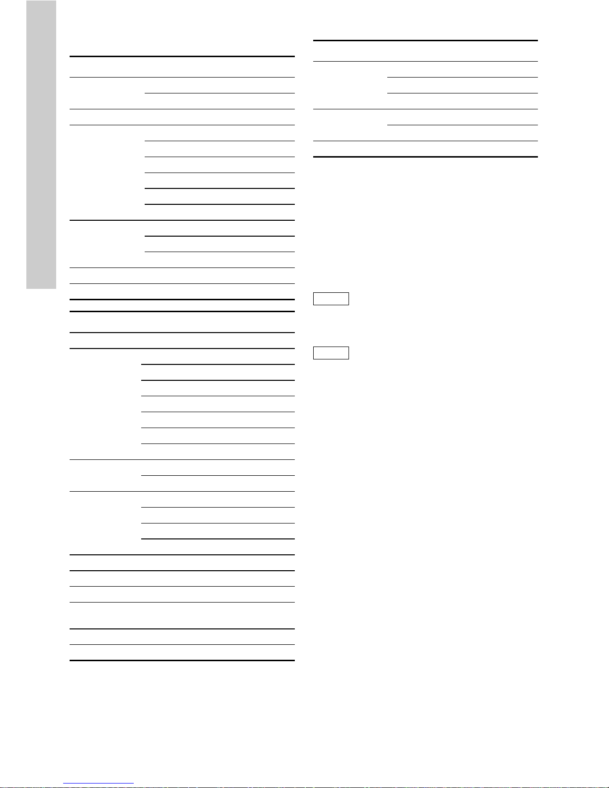
10.4 Parameter settings
Make a note here of the parameter settings for the
device.
TM03 6994 4506
0
5
10
15
100%
6
789
10
20
Xp = 40
Xp = 20
[mA]
Current output
Measured
value
Setpoint
[m/A]
[mS/cm]
Setup
Controller
Pulse freq. S1 _____ / min
Pulse freq. S2 _____ / min
Ctrl. direction S1
__ downward
__ upward
Ctrl. direction S2
__ downward
__ upward
Hysteresis _____ μS
Int. pulse period _____ s
Min. switch-on _____ s
Delay control
Delay ctrl.
__ off
__ on
Delay ctrl. _____ s
Analog output
Select output
__ 0-20 mA
__ 4-20 mA
Start 0/4 mA _____ μS
End 20 mA _____ μS
Analog output __ measured value
Temper. coeff. _____ % / °C
Cell const. _____
Measur. range _____
Averaging
__ on
__ off
Temperature compensation
Temp. compens.
__ Automat.comp.
__ Manual comp.
Manual temp. _____ °C
Controller settings
Setpoint 1 _____ μS
Prop. band XP S1 _____ μS
Reset time TN S1 _____ s
Setpoint 2 _____ μS
Prop. band XP S2 _____ μS
Reset time TN S2 _____ s
Alarm
Alarm value A1 _____ μS
Alarm value A2 _____ μS
Delay _____ s
Page 17

English (GB)
17
11. Initial operation and settings
11.1 Initial steps for operation
Once the assembly and connection steps have been
completed, carry out the following steps when using
the device for the first time.
1. Switch on the power supply.
2. If required, set the measuring range.
3. Check the entered cell constants.
4. If necessary, perform a cable compensation (for a
conductive measuring cell).
5. Set the parameters for the device function.
Check the outputs and secondary devices.
12. Operation
12.1 Device layout for Conex® DIS-C
12.1.1 Control and display elements
The Conex
®
DIS-C conductivity measuring amplifier
is operated using a touch-sensitive membrane
keypad.
Fig. 16 Control and display elements
Display
Control elements
Display fields
Fig. 17 Display fields
Warning
Before connecting the power supply,
ensure that the supply voltage
corresponds to the power supply specified
on the nameplate!
Note
Notes or instructions that make the job
easier and ensure safe operation.
TM03 6995 4506
Pos. Description
1LCD display
1
2
6
345
Pos. Function Name
2
Menu control button
[Up]
3[Left]
4[Down]
5 [Right]
6
Button for returning to
start menu
[OK]
TM03 6996 4506
Pos. Description
1a
Measuring value display
• Displays the current measured value
in MΩ, μS, mS (depending on the
selected measuring range).
1b
Temperature display
• Displays the temperature used for
compensation. Depending on the
setting, this is either the manually
specified temperature or the
temperature measured using the
temperature sensor.
1c
Relay 1 switching status
• A filled rectangle indicates
switched-on status.
1d
Relay 2 switching status
• A filled rectangle indicates
switched-on status.
1e
Control function
• Displays the preselected regulation
type.
1f Display of active menu control buttons.
Page 18
English (GB)
18
12.2 Menu control
12.3 Navigation in the menus
• To navigate in and between menus, use the [Up]
and [Down] buttons.
• Use the [Right] button to open the menu next to
it. The currently active menu control buttons are
displayed in the corresponding line.
• Use the [Left] button to save values.
• Use [OK] to exit the menu and return to the start
display.
Main menu Default values
Temp. compens.
Temp. compens. Manual comp.
Manual temp. 025 °C
Enter password Enter password Code 086
Controller
Setpoint S1 02.5 μS
Prop. and xp S1 10 %
Reset time TN S1 000 s
Setpoint S2 02.0 μS
Prop. band xp S2 10 %
Reset time TN S2 000 s
Alarm values
Alarm value A1 00.0 μS
Alarm value A2 02.0 μS
Delay 0.05 s
Setup See table below
Service See table below
Setup menu Default values
Corr. temp. Corr. temp. 0 °C
Contr. param.
Pulse freq. S1 0-180 / min
Pulse freq. S2 0-180 / min
Ctrl. direction S1 Downward control
Ctrl. direction S2 Upward control
Hysteresis 00.1 μS
Int. pulse period 10 s
Min. switch-on 0.5 s
Delay ctrl.
Delay ctrl. off
Delay ctrl. 180 s
Analog output
Select output 0-20 mA
Start 0/4 mA 00.0 μS
End 20 mA 200.0 μS
Analog output Measured value
Language Sel. language Deutsch
Temper. coeff. Temper. coeff. 0.0 % / °C
Cell const. Cell const. 0.050
Cable
compens.
Cable compens. 00.0 μS
Measur. range Measur. range 20.00 μS
Averaging Averaging off
Service menu Default values
Product info
Unit No. No. 041
Software date M/Y 1.00
Product. date M/Y 1.00
Analog input
Input 1 -019
Input 2 000 °C
Delete setting Delete setting
Note
Important menu selections and changes to
data are code-protected to prevent
unauthorised access.
Note
The order of the settings in the following
section is different to the order of menu
navigation. This section describes the
basic settings that are made first during
setup.
Page 19

English (GB)
19
12.4 Setup
The "Setup" menu contains settings that need to be
made or checked the first time the Conex
®
DIS-C is
used.
1. Press the [Down] button to navigate to the
"Setup" menu.
2. Press the [Right] button to open the "Setup"
menu.
3. Press the [Down] button to navigate to the
submenus.
In the submenus, it is possible to enter settings
for the following values:
• temperature correction
• control parameters
• switch-on delay
• analog output
• language
• temperature coefficient
• cell constant C
• bus address
• cable compensation/zero point
• measuring range
• averaging on/off.
12.4.1 Temperature correction
Because the temperature sensor is connected using
a 2-conductor method, this can result in deviations in
temperature measurement and display.
These deviations can be corrected within a range of
± 5 °C.
1. Press the [Right] button to open the "Corr. temp."
menu.
2. Press the [Right] button to start value input.
3. Press the [Up] and [Down] buttons to set the
value.
12.4.2 Control parameters
The first time the device is used, the regulatory
functions must be defined.
In the "Contr. param." menu, the following values
can be set:
• pulse frequency S1
• pulse frequency S2
• hysteresis
• pulse + pause
• minimum impulse.
1. Press the [Right] button to open the
"Contr. param." menu.
2. Press the [Down] button to navigate to the
submenus.
Pulse frequency S1/S2
1. Press the [Right] button to open the "Pulse
freq. S1" or "Pulse freq. S2" menu.
2. Press the [Up] and [Down] buttons to set the
value.
TM03 6997 4506TM03 6998 4506TM03 6999 4506
Alarm
Setup
Corr. temp.
0.0 °C
TM03 6998 4506
Note
Setting for a limit value: Xp = O.
Setting for an intermittent pulse regulator:
Xp > O, pulse frequency = 0.
Setting for a pulse frequency regulator:
Xp > O, pulse frequency > 0.
Note
Pulse frequency setting = maximum
number of impulses per minute. Set the
appropriate pulse frequency for the
connected control element.
Note
It is possible to make separate control
parameter settings for S1 and S2.
TM03 6998 4506
Corr. temp.
Contr. param.
Corr. temp.
Contr. param.
Page 20

English (GB)
20
Control direction S1/S2
By default, the control direction is set to exceeded (=
downwards) for S1, and for S2 it is set to upwards.
This means that if the value set for setpoint S1 is
exceeded, relay 1 is switched, and if the value drops
below setpoint S2, relay 2 is switched.
It is possible to change the control direction for S1
and S2.
1. Press the [Right] button to open the
"Ctrl. direction S1" or "Ctrl. direction S2" menu.
2. Press the [Up] and [Down] buttons to set the
value.
Hysteresis
The hysteresis setting only takes effect for a limit
value. If a setting is made, the hysteresis band
surrounds the selected setpoint symmetrically. If the
setpoint S1 is set to 0.500 mS and the hysteresis
setting is set to 0.010 mS, the relay switches on or
off (depending on the control direction) at 0.505 mS
and 0.495 mS.
1. Press the [Right] button to open the "Hysteresis"
menu.
2. Press the [Up] and [Down] buttons to set the
value.
Intermittent pulse period
The factory setting for the intermittent pulse period is
10 seconds. This setting has proved ideal for nearly
all applications.
1. Press the [Right] button to open the "Int. pulse
period" menu.
2. Press the [Up] and [Down] buttons to set the
value.
Minimum impulse/minimum switch-on time
The minimum switch-on time determines the shortest
drive pulse in the intermittent pulse period
regulation.
The intermittent pulse period setting must always be
at least twice as long as the minimum switch-on
time.
1. Press the [Right] button to open the
"Min. switch-on" menu.
2. Press the [Up] and [Down] buttons to set the
value.
12.4.3 Switch-on delay
If the switch-on delay of the Conex
®
DIS-C is
activated, the controller is not activated until the
specified time has elapsed after the power supply to
the device has been switched on. This menu can be
used to switch the switch-on delay on and off, and if
the switch-on delay is activated, the delay duration
can be entered.
Activating/deactivating the switch-on delay
1. Press the [Right] button to open the "Delay
control" menu.
2. Press the [Right] button to switch between on
and off.
Setting the switch-on delay time
1. Press the [Right] button to open the value input
display.
2. Press the [Up] and [Down] buttons to set the
value.
TM03 6998 4506TM03 6998 4506TM03 6998 4506
Ctrl. direction
Upward control
Hysteresis
0.010 mS
Int. pulse period
10 sec.
TM03 6999 4506TM03 6998 4506TM03 6998 4506
Min. switch-on
0.5 sec.
Contr. param.
Delay ctrl.
Delay ctrl.
On
Page 21

English (GB)
21
12.4.4 Analog output
Using the analog output, it is possible to choose
whether the measured value is signalled externally
as a registry output, or it is possible to choose the
switching points S1 or S2 as continuous control
outputs. Any range of 0 to 20 mA or 4 to 20 mA
within the measuring range can be assigned to the
analog output. The indicated measuring range is
defined by the start and end values. This also
determines the direction of the analog output.
• Press the [Right] button to open the "Analog
output" menu.
The following settings are made in the "Analog
output" menu:
• switching between 0 to 20 mA and 4 to 20 mA
• analog output start value
• analog output end value
• assigning analog output.
Switching between 0 to 20 mA and 4 to 20 mA
1. Press the [Right] button to choose between
0-20 mA and 4-20 mA.
2. Press the [Down] button to open the
"Start 0/4 mA" submenu.
Analog output start value
1. Press the [Right] button to open the value input
display.
2. Press the [Up] and [Down] buttons to set the
value.
3. Press the [Right] button to save the entry.
4. Press the [Down] button to open the "End 20 mA"
submenu.
Analog output end value
1. Press the [Right] button to open the value input
display.
2. Press the [Up] and [Down] buttons to set the
value.
3. Press the [Left] button to save the entry.
4. Press the [Down] button to open the "Analog
output" submenu.
Assigning analog output
1. Press the [Right] button to choose between the
measured value, continuous controller 1 and
continuous controller 2.
12.4.5 Language
The "Language" menu is used to determine the
language for the Conex
®
DIS-C.
1. Press the [Right] button to open the "Language"
menu.
2. Press the [Right] button to choose between the
languages (German, English, French).
TM03 6998 4506TM03 6998 4506
Select output
0-20 mA
Start 0/4 mA
0.000 mS
TM03 6999 4506TM03 6999 4506TM03 6999 4506TM03 6999 4506TM03 6999 4506
End 20 mA
2.000 mS
Analog output
Measured value
Analog output
Cont. ctrl. S1
Analog output
Cont. ctrl. S2
Sel. language
Deutsch
Page 22

English (GB)
22
12.4.6 Temperature coefficient
This menu is used for displaying and setting the
temperature coefficient.
Because different measuring fluids have different
temperature coefficients, the appropriate coefficient
must be set. The setting range is 0.0 to 8.0 % / °C.
The factory setting is 2.5 % / °C, which is suitable for
many applications.
1. Press the [Right] button to open the
"Temper. coeff." menu.
2. Press the [Right] button to open the value input
display.
3. Press the [Up] and [Down] buttons to set the
value.
12.4.7 Cell constant C
The mechanical dimensions used for the
measurement of active surfaces of the measuring
cell are defined in the cell constant. The measuring
cell is characterised by the cell constant.
1. Press the [Right] button to open the "Cell const."
menu.
2. Press the [Right] button to open the value input
display.
3. Press the [Up] and [Down] buttons to set the
value.
Cable compensation (only for conductive
measurement)
The capacity of the cable can lead to an incorrect
value, particularly for small measuring ranges.
This incorrect value can be corrected as follows:
1. Press the [Right] button to select the "Cable
compens." menu.
2. Hold the connected, dry measuring cell in the air.
– If the top line of the display reads a measured
value, i.e. the value 0.00 is not displayed,
cable compensation must be performed.
3. Simultaneously press the [Left] and [Down]
buttons.
– If the compensation is successful, the value
0.00 is displayed.
12.4.8 Measuring range
In this menu, the required measuring range for the
device can be set (MΩ, μS, mS).
1. Press the [Right] button to open the
"Measur. range" menu.
2. Press the [Right] button (several times) to select
a measuring range.
TM03 6998 4506TM03 6999 4506TM03 6999 4506
Language
Temper. coeff.
Temper. coeff.
0.0 % / °C
Cell const.
0.050
TM03 7000 4506TM03 6999 4506TM03 6999 4506
Note
When setting the measuring range, ensure
that it is suitable for the cell constant of the
measuring cell. See section 7. Technical
data.
0.00 μS
Press
Measur. range
2.000 μS
Measur. range
20.00 MOhm
Page 23

English (GB)
23
12.4.9 Averaging on/off
In this menu, the averaging function can be switched
on or off. If the averaging function is switched on, the
mean of the last 10 measured values is calculated
and displayed as the measured value.
1. Press the [Right] button to open the "Averaging"
menu.
2. Press the [Right] button to select averaging on or
off.
12.5 Relay menu (S1 S2)
In the relay menu (S1 S2), it is possible to choose
between manual and automatic operation. In manual
operation, the relays S1 and S2 can be switched on
and off separately.
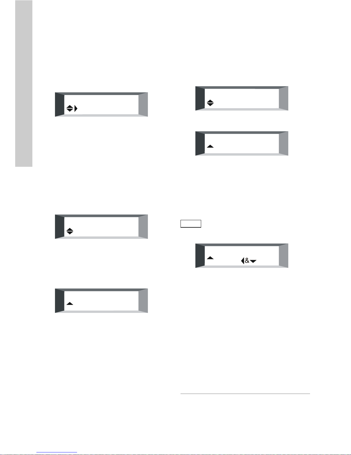
12.5.1 Automatic and manual operation
In automatic operation, the relay contacts are
switched by the built-in controller. "Auto" is shown in
the display.
In manual operation, the relay is switched manually.
"Man" is shown in the display.
Switching between automatic and manual
operation:
• Press the [Right] button to switch the controller to
manual or automatic operation.
12.5.2 S1/S2 in manual operation
Switching the relays S1/S2 on and off:
1. Press the [Up] button to select the chosen relay
(S1/S2).
– The corresponding symbol flashes.
2. Press the [Right] button to switch the chosen
relay (S1 or S2) on or off.
– The switch status of the relay is displayed as
follows:
Relay ON = symbol filled
Relay OFF = symbol not filled.
12.6 Temperature compensation
Temperature compensation cancels out the effect of
temperature dependency of the medium. It is based
on a reference temperature of 25 °C.
This temperature compensation can be performed
automatically via a connected temperature sensor or
manually by entering the relevant temperature.
• Select the "Temp. compens." menu.
Switching between manual and automatic
compensation:
• Press the [Right] button to select between
manual and automatic compensation.
Selecting the default temperature for manual
compensation
1. Press the [Down] button to open the "Manual
temp." menu.
2. Press the [Right] button to open the temperature
selection display.
3. Press the [Up] and [Down] buttons to select the
temperature.
TM03 6999 4506
Note
The description of the rest of the menus
now continues in the order of menu
navigation.
TM03 6997 4506TM03 7001 4506
Note
If the relays are switched on manually,
they remain switched on until they are
switched off again, or until control is
switched back to automatic.
Note
Switching to automatic operation is only
possible if the arrow to the right of the
"Man" text is visible.
Averaging
Off
TM03 6998 4506TM03 6999 4506
Temp. compens.
Automat. comp.
Default temp.
25.5 °C
Page 24

English (GB)
24
12.7 Displaying / changing code
The device can be protected against unauthorised or
unintentional changing of the programmed data.
Two release codes are stored:
• Code 086: General access to all functions.
• Code 011: Access to temperature compensation
and controller settings.
In all other code settings, the device is protected
against unintentional changes to data. If a code is
set and a locked menu is selected, the operator is
prompted to enter the code.
Displaying the code
• Press the [Right] button to open the "Enter
password" menu.
– The current code is displayed.
Changing the code
1. Press the [Right] button to open the "Enter
password" menu.
2. Press the [Up] and [Down] buttons to enter the
required code in the range 000 to 2000.
– Pressing the [Up] button once increases the
value by +1. If the button is held down for
longer, the value increases automatically.
– Pressing the [Down] button once decreases the
value by -1. If the button is held down for
longer, the value decreases automatically.
3. Press the [Left] button to save the entry.
12.8 Controller settings
In the "Controller" menu, the following values are
set:
•setpoint S1
• proportional band Xp S1
• reset time Tn (I part) S1
•setpoint S2
• proportional band Xp S2
• reset time Tn (I part) S2.
1. Press the [Right] button to open the "Controller"
menu.
2. Press the [Up] and [Down] buttons to select the
required value.
3. Press the [Right] button to open the value input
display.
12.8.1 Setpoint setting S1/S2
The setpoints S1 and S2 are set separately and can
have different values within the measuring range.
1. Press the [Right] button to open the value input
display.
2. Press the [Up] and [Down] buttons to set the
value.
Note
Important menu selections and changes to
data are code-protected to prevent
unauthorised access.
TM03 6998 4506TM03 6999 4506TM03 7002 4506
Temp. compens.
Enter password
Enter password
011 Code
Enter password
011 Code
Note
This entry is only possible if the
corresponding controller function is
already set in the "Setup" menu.
TM03 6998 4506TM03 6998 4506
Enter password
Controller
Setpoint 2
0.000 mS
Page 25

English (GB)
25
12.8.2 Proportional band Xp S1/S2
The proportional band Xp (P behaviour) is set
separately for both setpoints in the range 1 to
3000 %.
1. Press the [Right] button to open the value input
display.
2. Press the [Up] and [Down] buttons to set the
value.
12.8.3 Reset time Tn (I part) S1/S2
The reset time Tn (I part) is set separately for both
setpoints in the range 0 to 3000 seconds.
If the reset time Tn is 0 seconds, the I part is
deactivated.
1. Press the [Right] button to open the value input
display.
2. Press the [Up] and [Down] buttons to set the
value.
12.9 Alarm value setting A1/A2
For the limit value alarm, the alarm values A1 and A2
are set separately. The switch direction for alarm
value A1 is set to "exceed", and for alarm value A2 it
is set to "drop below". If the alarm value 1 is
exceeded or if the value drops below alarm value 2,
relay 3 is switched after the specified delay time has
elapsed.
The alarm message is delayed by the specified time.
If the delay time is set to 000 seconds, the alarm
message of the limit value alarm is raised
immediately.
Setting the alarm values
1. Press the [Right] button to open the "Alarm
values" menu.
2. Press the [Up] and [Down] buttons to select the
required value (A1, A2).
3. Press the [Right] button to open the value input
display.
4. Press the [Up] and [Down] buttons to set the
value.
Setting the alarm delay time
1. Press the [Up] and [Down] buttons to select
"Delay".
2. Press the [Right] button to open the value input
display.
3. Press the [Up] and [Down] buttons to set the
value.
Note
Setting for a limit value: Xp = O.
Setting for an intermittent pulse controller
or pulse frequency controller: Xp > O.
TM03 6998 4506TM03 6999 4506
Prop. band xp
3000 %
Reset time TN
000 sec.
TM03 6998 4506TM03 6999 4506
Controller
Alarm values
Delay
000 s
Page 26
English (GB)
26
12.10 Service
The "Service" menu contains service information and
utilities.
The "Service" menu contains the following
options:
• device data
• analog inputs
• resetting factory settings.
• Press the [Right] button to open the "Service"
menu.
12.10.1 Device data
1. Press the [Right] button to open the "Product
info" menu.
2. Press the [Up] and [Down] buttons to switch
between the following displays.
Device number
Displays the serial number.
Software status
Displays the latest revision date of the software
(e.g. 1.00: The software revision status is
January 2000).
Production date
Displays the date of manufacture of the device
(e.g. 3.00: The device was produced in March 2000).
12.10.2 Analog inputs/test
In this menu, the analog inputs are tested. The input
signals are displayed in mV (analog input 1) and °C
(analog input 2).
1. Press the [Right] button to open the "Analog
input" menu.
2. Press the [Up] and [Down] buttons to switch
between the following displays:
12.10.3 Deleting data/resetting factory settings
In some circumstances it may be necessary to
restore the device to its delivered status. All values
set by the customer are overwritten with the factory
settings.
The initial settings on the device must then be made
again.
1. Press the [Right] button to open the "Delete
setting" menu.
2. Simultaneously press and hold down the [Left]
and [Down] buttons.
– "Please wait!!!" is displayed.
Deleting the data takes approximately 10 seconds.
When this display disappears, the Conex
®
DIS-C is
restored to the factory settings.
13. Disposal
This product or parts of it must be disposed of in an
environmentally sound way:
1. Use the public or private waste collection service.
2. If this is not possible, contact the nearest
Grundfos company or service workshop.
Subject to alterations.
TM03 6998 4506TM03 7003 4506TM03 7004 4506
Setup
Service
Software date
M/Y 1.00
Product. date
M/Y 3.00
TM03 7003 4506TM03 7004 4506
Note
Before deleting the memory, make a note
of the important parameter settings.
TM03 7000 4506
Analog input
Input 1 056 mV
Analog output
Input 2 023 °C
Delete setting
Press
Page 27

Declaration of conformity
27
Declaration of conformity 1
GB: EC/EU declaration of conformity
We, Grundfos, declare under our sole responsibility that the product
Conex DIS-C, to which the declaration below relates, is in conformity
with the Council Directives listed below on the approximation of the
laws of the EC/EU member states.
DE: EG-/EU-Konformitätserklärung
Wir, Grundfos, erklären in alleiniger Verantwortung, dass das Produkt
Conex DIS-C, auf das sich diese Erklärung bezieht, mit den
folgenden Richtlinien des Rates zur Angleichung der
Rechtsvorschriften der EG-/EU-Mitgliedsstaaten übereinstimmt.
ES: Declaración de conformidad de la CE/UE
Grundfos declara, bajo su exclusiva responsabilidad, que el producto
Conex DIS-C al que hace referencia la siguiente declaración cumple
lo establecido por las siguientes Directivas del Consejo sobre la
aproximación de las legislaciones de los Estados miembros de la
CE/UE.
FR: Déclaration de conformité CE/UE
Nous, Grundfos, déclarons sous notre seule responsabilité, que le
produit Conex DIS-C, auquel se réfère cette déclaration, est
conforme aux Directives du Conseil concernant le rapprochement
des législations des États membres CE/UE relatives aux normes
énoncées ci-dessous.
IT: Dichiarazione di conformità CE/UE
Grundfos dichiara sotto la sua esclusiva responsabilità che il prodotto
Conex DIS-C, al quale si riferisce questa dichiarazione, è conforme
alle seguenti direttive del Consiglio riguardanti il riavvicinamento delle
legislazioni degli Stati membri CE/UE.
NL: EG/EU-conformiteitsverklaring
Wij, Grundfos, verklaren geheel onder eigen verantwoordelijkheid dat
product Conex DIS-C, waarop de onderstaande verklaring betrekking
heeft, in overeenstemming is met de onderstaande Richtlijnen van de
Raad inzake de onderlinge aanpassing van de wetgeving van de
EG-/EU-lidstaten.
PT: Declaração de conformidade CE/UE
A Grundfos declara sob sua única responsabilidade que o produto
Conex DIS-C, ao qual diz respeito a declaração abaixo, está em
conformidade com as Directivas do Conselho sobre a aproximação
das legislações dos Estados Membros da CE/UE.
– EMC Directive (2014/30/EU).
Standards used:
EN 61326-1:2013,
EN 61000-3-2:2015, EN 61000-3-3:2014.
– Low Voltage Directive (2014/35/EU).
Standard used:
EN 61010-1:2011-07.
This EC/EU declaration of conformity is only valid when published as
part of the Grundfos instructions.
Pfinztal, 20th April 2016
Ulrich Stemick
Technical Director
Grundfos Water Treatment GmbH
Reetzstr. 85, D-76327 Pfinztal, Germany
Person authorised to compile the technical file and
empowered to sign the EC/EU declaration of conformity.
Page 28

Grundfos companies
Argentina
Bombas GRUNDFOS de Argentina S.A.
Ruta Panamericana km. 37.500 Centro
Industrial Garin
1619 - Garin Pcia. de B.A.
Phone: +54-3327 414 444
Telefax: +54-3327 411 111
Australia
GRUNDFOS Pumps Pty. Ltd.
P.O. Box 2040
Regency Park
South Australia 5942
Phone: +61-8-8461-4611
Telefax: +61-8-8340 0155
Austria
GRUNDFOS Pumpen Vertrieb
Ges.m.b.H.
Grundfosstraße 2
A-5082 Grödig/Salzburg
Tel.: +43-6246-883-0
Telefax: +43-6246-883-30
Belgium
N.V. GRUNDFOS Bellux S.A.
Boomsesteenweg 81-83
B-2630 Aartselaar
Tél.: +32-3-870 7300
Télécopie: +32-3-870 7301
Belarus
Представительство ГРУНДФОС в
Минске
220125, Минск
ул. Шафарнянская, 11, оф. 56
Тел.: +7 (375 17) 286 39 72, 286 39 73
Факс: +7 (375 17) 286 39 71
E-mail: minsk@grundfos.com
Bosnia/Herzegovina
GRUNDFOS Sarajevo
Trg Heroja 16,
BiH-71000 Sarajevo
Phone: +387 33 713 290
Telefax: +387 33 659 079
e-mail: grundfos@bih.net.ba
Brazil
BOMBAS GRUNDFOS DO BRASIL
Av. Humberto de Alencar Castelo
Branco, 630
CEP 09850 - 300
São Bernardo do Campo - SP
Phone: +55-11 4393 5533
Telefax: +55-11 4343 5015
Bulgaria
Grundfos Bulgaria EOOD
Slatina District
Iztochna Tangenta street no. 100
BG - 1592 Sofia
Tel. +359 2 49 22 200
Fax. +359 2 49 22 201
email: bulgaria@grundfos.bg
Canada
GRUNDFOS Canada Inc.
2941 Brighton Road
Oakville, Ontario
L6H 6C9
Phone: +1-905 829 9533
Telefax: +1-905 829 9512
China
Grundfos Alldos
Dosing & Disinfection
ALLDOS (Shanghai) Water Technology
Co. Ltd.
West Unit, 1 Floor, No. 2 Building (T 4-2)
278 Jinhu Road, Jin Qiao Export
Processing Zone
Pudong New Area
Shanghai, 201206
Phone: +86 21 5055 1012
Telefax: +86 21 5032 0596
E-mail:
grundfosalldos-CN@grundfos.com
China
GRUNDFOS Pumps (Shanghai) Co. Ltd.
10F The Hub, No. 33 Suhong Road
Minhang District
Shanghai 201106
PRC
Phone: +86-21 6122 5222
Telefax: +86-21 6122 5333
Croatia
GRUNDFOS CROATIA d.o.o.
Cebini 37, Buzin
HR-10010 Zagreb
Phone: +385 1 6595 400
Telefax: +385 1 6595 499
www.hr.grundfos.com
Czech Republic
GRUNDFOS s.r.o.
Čapkovského 21
779 00 Olomouc
Phone: +420-585-716 111
Telefax: +420-585-716 299
Denmark
GRUNDFOS DK A/S
Martin Bachs Vej 3
DK-8850 Bjerringbro
Tlf.: +45-87 50 50 50
Telefax: +45-87 50 51 51
E-mail: info_GDK@grundfos.com
www.grundfos.com/DK
Estonia
GRUNDFOS Pumps Eesti OÜ
Peterburi tee 92G
11415 Tallinn
Tel: + 372 606 1690
Fax: + 372 606 1691
Finland
OY GRUNDFOS Pumput AB
Trukkikuja 1
FI-01360 Vantaa
Phone: +358-(0)207 889 500
Telefax: +358-(0)207 889 550
France
Pompes GRUNDFOS Distribution S.A.
Parc d’Activités de Chesnes
57, rue de Malacombe
F-38290 St. Quentin Fallavier (Lyon)
Tél.: +33-4 74 82 15 15
Télécopie: +33-4 74 94 10 51
Germany
GRUNDFOS Water Treatment GmbH
Reetzstraße 85
D-76327 Pfinztal (Söllingen)
Tel.: +49 7240 61-0
Telefax: +49 7240 61-177
E-mail: gwt@grundfos.com
Germany
GRUNDFOS GMBH
Schlüterstr. 33
40699 Erkrath
Tel.: +49-(0) 211 929 69-0
Telefax: +49-(0) 211 929 69-3799
E-mail: infoservice@grundfos.de
Service in Deutschland:
E-mail: kundendienst@grundfos.de
Greece
GRUNDFOS Hellas A.E.B.E.
20th km. Athinon-Markopoulou Av.
P.O. Box 71
GR-19002 Peania
Phone: +0030-210-66 83 400
Telefax: +0030-210-66 46 273
Hong Kong
GRUNDFOS Pumps (Hong Kong) Ltd.
Unit 1, Ground floor
Siu Wai Industrial Centre
29-33 Wing Hong Street &
68 King Lam Street, Cheung Sha Wan
Kowloon
Phone: +852-27861706 / 27861741
Telefax: +852-27858664
Hungary
GRUNDFOS Hungária Kft.
Park u. 8
H-2045 Törökbálint,
Phone: +36-23 511 110
Telefax: +36-23 511 111
India
GRUNDFOS Pumps India Private
Limited
118 Old Mahabalipuram Road
Thoraipakkam
Chennai 600 097
Phone: +91-44 4596 6800
Indonesia
PT. GRUNDFOS POMPA
Graha Intirub Lt. 2 & 3
Jln. Cililitan Besar No.454. Makasar,
Jakarta Timur
ID-Jakarta 13650
Phone: +62 21-469-51900
Telefax: +62 21-460 6910 / 460 6901
Ireland
GRUNDFOS (Ireland) Ltd.
Unit A, Merrywell Business Park
Ballymount Road Lower
Dublin 12
Phone: +353-1-4089 800
Telefax: +353-1-4089 830
Italy
GRUNDFOS Pompe Italia S.r.l.
Via Gran Sasso 4
I-20060 Truccazzano (Milano)
Tel.: +39-02-95838112
Telefax: +39-02-95309290 / 95838461
Japan
GRUNDFOS Pumps K.K.
Gotanda Metalion Bldg. 5F,
5-21-15, Higashi-gotanda
Shiagawa-ku, Tokyo,
141-0022 Japan
Phone: +81 35 448 1391
Telefax: +81 35 448 9619
Page 29

Grundfos companies
Korea
GRUNDFOS Pumps Korea Ltd.
6th Floor, Aju Building 679-5
Yeoksam-dong, Kangnam-ku, 135-916
Seoul, Korea
Phone: +82-2-5317 600
Telefax: +82-2-5633 725
Latvia
SIA GRUNDFOS Pumps Latvia
Deglava biznesa centrs
Augusta Deglava ielā 60, LV-1035, Rīga,
Tālr.: + 371 714 9640, 7 149 641
Fakss: + 371 914 9646
Lithuania
GRUNDFOS Pumps UAB
Smolensko g. 6
LT-03201 Vilnius
Tel: + 370 52 395 430
Fax: + 370 52 395 431
Malaysia
GRUNDFOS Pumps Sdn. Bhd.
7 Jalan Peguam U1/25
Glenmarie Industrial Park
40150 Shah Alam
Selangor
Phone: +60-3-5569 2922
Telefax: +60-3-5569 2866
Mexico
Bombas GRUNDFOS de México S.A. de
C.V.
Boulevard TLC No. 15
Parque Industrial Stiva Aeropuerto
Apodaca, N.L. 66600
Phone: +52-81-8144 4000
Telefax: +52-81-8144 4010
Netherlands
GRUNDFOS Netherlands
Veluwezoom 35
1326 AE Almere
Postbus 22015
1302 CA ALMERE
Tel.: +31-88-478 6336
Telefax: +31-88-478 6332
E-mail: info_gnl@grundfos.com
New Zealand
GRUNDFOS Pumps NZ Ltd.
17 Beatrice Tinsley Crescent
North Harbour Industrial Estate
Albany, Auckland
Phone: +64-9-415 3240
Telefax: +64-9-415 3250
Norway
GRUNDFOS Pumper A/S
Strømsveien 344
Postboks 235, Leirdal
N-1011 Oslo
Tlf.: +47-22 90 47 00
Telefax: +47-22 32 21 50
Poland
GRUNDFOS Pompy Sp. z o.o.
ul. Klonowa 23
Baranowo k. Poznania
PL-62-081 Przeźmierowo
Tel: (+48-61) 650 13 00
Fax: (+48-61) 650 13 50
Portugal
Bombas GRUNDFOS Portugal, S.A.
Rua Calvet de Magalhães, 241
Apartado 1079
P-2770-153 Paço de Arcos
Tel.: +351-21-440 76 00
Telefax: +351-21-440 76 90
Romania
GRUNDFOS Pompe România SRL
Bd. Biruintei, nr 103
Pantelimon county Ilfov
Phone: +40 21 200 4100
Telefax: +40 21 200 4101
E-mail: romania@grundfos.ro
Russia
ООО Грундфос
Россия, 109544 Москва, ул. Школьная
39
Тел. (+7) 495 737 30 00, 564 88 00
Факс (+7) 495 737 75 36, 564 88 11
E-mail grundfos.moscow@grundfos.com
Serbia
GRUNDFOS Predstavništvo Beograd
Dr. Milutina Ivkovića 2a/29
YU-11000 Beograd
Phone: +381 11 26 47 877 / 11 26 47
496
Telefax: +381 11 26 48 340
Singapore
GRUNDFOS (Singapore) Pte. Ltd.
25 Jalan Tukang
Singapore 619264
Phone: +65-6681 9688
Telefax: +65-6681 9689
Slovakia
GRUNDFOS s.r.o.
Prievozská 4D
821 09 BRATISLAVA
Phona: +421 2 5020 1426
sk.grundfos.com
Slovenia
GRUNDFOS LJUBLJANA, d.o.o.
Leskoškova 9e, 1122 Ljubljana
Phone: +386 (0) 1 568 06 10
Telefax: +386 (0)1 568 0619
E-mail: tehnika-si@grundfos.com
South Africa
Grundfos (PTY) Ltd.
Corner Mountjoy and George Allen
Roads
Wilbart Ext. 2
Bedfordview 2008
Phone: (+27) 11 579 4800
Fax: (+27) 11 455 6066
E-mail: lsmart@grundfos.com
Spain
Bombas GRUNDFOS España S.A.
Camino de la Fuentecilla, s/n
E-28110 Algete (Madrid)
Tel.: +34-91-848 8800
Telefax: +34-91-628 0465
Sweden
GRUNDFOS AB
(Box 333) Lunnagårdsgatan 6
431 24 Mölndal
Tel.: +46 31 332 23 000
Telefax: +46 31-331 94 60
Switzerland
GRUNDFOS ALLDOS International AG
Schönmattstraße 4
CH-4153 Reinach
Tel.: +41-61-717 5555
Telefax: +41-61-717 5500
E-mail:
grundfosalldos-CH@grundfos.com
Switzerland
GRUNDFOS Pumpen AG
Bruggacherstrasse 10
CH-8117 Fällanden/ZH
Tel.: +41-44-806 8111
Telefax: +41-44-806 8115
Taiwan
GRUNDFOS Pumps (Taiwan) Ltd.
7 Floor, 219 Min-Chuan Road
Taichung, Taiwan, R.O.C.
Phone: +886-4-2305 0868
Telefax: +886-4-2305 0878
Thailand
GRUNDFOS (Thailand) Ltd.
92 Chaloem Phrakiat Rama 9 Road,
Dokmai, Pravej, Bangkok 10250
Phone: +66-2-725 8999
Telefax: +66-2-725 8998
Turkey
GRUNDFOS POMPA San. ve Tic. Ltd.
Sti.
Gebze Organize Sanayi Bölgesi
Ihsan dede Caddesi,
2. yol 200. Sokak No. 204
41490 Gebze/ Kocaeli
Phone: +90 - 262-679 7979
Telefax: +90 - 262-679 7905
E-mail: satis@grundfos.com
Ukraine
Бізнес Центр Європа
Столичне шосе, 103
м. Київ, 03131, Україна
Телефон: (+38 044) 237 04 00
Факс.: (+38 044) 237 04 01
E-mail: ukraine@grundfos.com
United Arab Emirates
GRUNDFOS Gulf Distribution
P.O. Box 16768
Jebel Ali Free Zone
Dubai
Phone: +971-4- 8815 166
Telefax: +971-4-8815 136
United Kingdom
GRUNDFOS Pumps Ltd.
Grovebury Road
Leighton Buzzard/Beds. LU7 4TL
Phone: +44-1525-850000
Telefax: +44-1525-850011
U.S.A.
GRUNDFOS Pumps Corporation
17100 West 118th Terrace
Olathe, Kansas 66061
Phone: +1-913-227-3400
Telefax: +1-913-227-3500
Uzbekistan
Grundfos Tashkent, Uzbekistan The
Representative Office of Grundfos
Kazakhstan in Uzbekistan
38a, Oybek street, Tashkent
Телефон: (+998) 71 150 3290 / 71 150
3291
Факс: (+998) 71 150 3292
Addresses revised 25.01.2016
Page 30

www.grundfos.com
96709879 0416
ECM: 1182149
The name Grundfos, the Grundfos logo, and be think innovate are registered trademarks
owned by Grundfos Holding A/S or Grundfos A/S, Denmark. All rights reserved worldwide.
© Copyright Grundfos Holding A/S
 Loading...