

Page 1

Conex® DIA-1
Instrument amplifier and controller
Installation and operating instructions
GRUNDFOS INSTRUCTIONS
Page 2

2
Page 3

Conex® DIA-1
English (GB)
Installation and operating instructions. . . . . . . . . . . . . . . . . . . . . . . . . . . . . . . . . 4
Deutsch (DE)
Montage- und Betriebsanleitung . . . . . . . . . . . . . . . . . . . . . . . . . . . . . . . . . . . . 52
Español (ES)
Instrucciones de instalación y funcionamiento . . . . . . . . . . . . . . . . . . . . . . . . 100
Français (FR)
Notice d'installation et de fonctionnement. . . . . . . . . . . . . . . . . . . . . . . . . . . . 149
Ελληνικά (GR)
Οδηγίες εγκατάστασης και λειτουργίας . . . . . . . . . . . . . . . . . . . . . . . . . . . . . . 198
Italiano (IT)
Istruzioni di installazione e funzionamento . . . . . . . . . . . . . . . . . . . . . . . . . . . 254
Nederlands (NL)
Installatie- en bedieningsinstructies . . . . . . . . . . . . . . . . . . . . . . . . . . . . . . . . 303
Polski (PL)
Instrukcja montażu i eksploatacji . . . . . . . . . . . . . . . . . . . . . . . . . . . . . . . . . . 352
Português (PT)
Instruções de instalação e funcionamento . . . . . . . . . . . . . . . . . . . . . . . . . . . 401
Русский (RU)
Паспорт, Руководство по монтажу и эксплуатации . . . . . . . . . . . . . . . . . . 449
Slovensko (SI)
Navodila za montažo in obratovanje. . . . . . . . . . . . . . . . . . . . . . . . . . . . . . . . 498
Türkçe (TR)
Montaj ve kullanım kılavuzu . . . . . . . . . . . . . . . . . . . . . . . . . . . . . . . . . . . . . . 546
Declaration of conformity . . . . . . . . . . . . . . . . . . . . . . . . . . . . . . . . . . . . . . . . 596
Declaration of conformity RU . . . . . . . . . . . . . . . . . . . . . . . . . . . . . . . . . . . . . 597
Table of contents
3
Page 4

English (GB) Installation and operating instructions
Note
Caution
Note
English (GB)
Original installation and operating instructions
CONTENTS
Page
1. Symbols used in this document
2. A few words in advance
3. Instrument settings
4. General information
5. Applications
6. Safety
6.1 Obligations of the owner/operations
manager
6.2 Avoidance of danger
7. Identification
7.1 Nameplate
7.2 Type key, Conex
7.3 Type key, Conex
systems
8. Technical data
8.1 Design / enclosure class
8.2 General data
8.3 Electronic data and functions
8.4 Measuring ranges
8.5 Dimensions
9. Installation
9.1 Transport and storage
9.2 Unpacking
9.3 Installation requirements
9.4 Installation in control panel
9.5 Installation of wall-mounted enclosure
10. Commissioning / electrical
connections
10.1 Terminals
10.2 Power supply connection
10.3 Relay outputs
10.4 Current output
10.5 Connections of controller stop,
sample-water sensor and temperature
sensor
10.6 Connection of measuring cells
11. Operation
11.1 Control and display elements
11.2 Display elements during initial
commissioning
11.3 Software overview
11.4 Main menu
11.5 Se tup
11.6 Selection, configuration and
parameterisation of the controller
11.7 "Alarm" menu
11.8 Checking the settings in the "service"
menu
11.9 Calibration
11.10 Manual operation
®
DIA-1 controllers
®
DIA-1 preassembled
12. Fault finding
13. Maintenance
14. Disposal
4
5
6
8
8
8
8
8
8
1. Symbols used in this document
8
9
9
11
11
11
11
13
13
14
14
14
14
14
14
15
16
18
18
19
19
20
24
24
25
26
27
28
34
39
41
43
47
Warning
Prior to installation, read these installation
and operating instructions. Installation and
operation must comply with local
regulations and accepted codes of good
practice.
These complete installation and operating
instructions are also available on
www.Grundfos.com.
Warning
If these safety instructions are not
observed, it may result in personal injury.
If these safety instructions are not
observed, it may result in malfunction or
damage to the equipment.
Notes or instructions that make the job
easier and ensure safe operation.
51
51
51
4
Page 5

2. A few words in advance
The Conex® DIA-1 is a multipurpose device
designed to carry out high-precision measurements
and controls of pH value, redox potential, chlorine,
chlorine dioxide, ozone, hydrogen peroxide or
peracetic acid.
The integrated controller, the high-resolution
graphics display and the multilingual plain-text user
interface make complicated measuring and control
tasks in water chemistry much easier.
Just a few button inputs lead you to your goal.
The potentiostat helps save even more time, being
automatically matched to the various input variables.
The safety standard of the dosing process is raised
by the automatic open-circuit monitoring of the
current outputs.
The Conex
chlorine measuring and automatic pH value
compensation in one single device. For this purpose,
the Conex
and an interface for external instrument amplifiers.
Properties of the Conex
and controller include the following:
• all control functions including PID and
• manual or automatic temperature compensation
• logbook function: chronological recording of
• user coding function as a means of protection
• error message function for indication of
®
DIA-1 combines the functions of exact
®
DIA-1 features a pH sensor interface
®
DIA-1 measuring amplifier
continuous-action controls
calibration values with date and time
against access by unauthorised persons and for
system administration
non-functioning sensors.
English (GB)
5
Page 6

3. Instrument settings
English (GB)
General settings
Control of cleaning motor
(with measuring cell type AQC-D1/-D11)
Yes:_ No:_ Yes:_ No:_
Sample-water deficiency sensor
On:_ Off:_ sec.
Parameter settings
Chlorine
Temperature measurement Yes:_ No:_ Yes:_ No:_ Yes:_ No:_ Yes:_ No:_ Yes:_ No:_
Compensation of temperature Yes:_ No:_ Yes:_ No:_ Yes:_ No:_ Yes:_ No:_ Yes:_ No:_
pH measurement Yes : _ N o : _
Compensation of pH value Yes : _ N o : _
Measuring cell type
Measuring range mg/l (ppm) - - - - -
Sensor slope µA/ppm
Current output mA-----
Temperature measurement Yes:_ No:_ Yes:_ No:_
Temperature compensation Yes :_ No :_
Measuring cell type
Measuring range pH - -
Slope mV/pH
Current output mA - -
Maximum dosing time at constant load of 100 % of
Chlorine
dioxide
Dosing time monitoring
dosing capacity
Ozone Peroxide
pH Redox
Peracetic
acid
6
Page 7

Switching
controller
Limit contact
Two-position
controller
3-pos. crtl.
Continuous
controller
Controllers
Controller settings Controller parameters
Relay 1 Relay 2 Proportional band
On:_
Off:_
Switching direction
Downward/upward violation
Downwd.
Upwd.
interpulse period (PP) or pulse
frequency (PF) controller
PP:_
PF:_
Control direction
Downward or upward
Downwd.:_
Upwd.:_
Type of control
P:_
PI:_
PID:_
Setpoint
Internal:_
External:_
On:_
Off:_
Downwd.
Upwd.
PP:_
PF:_
Downwd.:_
Upwd.:_
P:_
PI:_
PID:_
Internal:_
External:_
Reset time TN
(PI/PID-control)
Deriv. action TV
(PI-control)
Pulse-interp. interval
(interpulse period controller)
Min. operation time
(interpulse period controller)
Max. frequency
(interpulse period controller)
%sec.
sec. %
sec. %
sec. sec.
sec.
Hz
Min. pulse width
(3-pos. crtl.)
Constant load
(two-pos.-/cont. controller)
Max. dosing rate
(two-pos.-/cont. controller)
Motor runtime
(3-pos. crtl.)
Hysteresis
(limit contact)
Type of control
Downward or upward
Down:_ Up:_
Setpoint
Internal:_ External:_
Control direction
Downward or upward
Down:_ Up:_
Type of control
P:_ PI:_ PID:_
Setpoint
Internal:_ External:_
English (GB)
7
Page 8

4. General information
Caution
DIA-1-A D1-X-AU-X-QS-T, W-G
314-331-10000
S/N: 07/85229
Conex DIA-1 pre-assembled
230/240V 50/60Hz, 25 VA, IP 65
4.00 bar
96698140P1107480785229
1
2
3
4
5
6
7
811
12
13
910
English (GB)
These installation and operating instructions
contain all information important for users of the
®
Conex
DIA-1:
• technical data
• instructions on commissioning, use and
maintenance
• safety information.
Should you require further information or should you
encounter problems that are not handled in sufficient
depth in this manual, please contact Grundfos.
We shall be pleased to support you with our
comprehensive know-how in the fields of measuring
and control technology as well as water treatment.
We always welcome suggestions on how to optimise
our installation and operating instructions to satisfy
our customers.
5. Applications
The Conex® DIA-1 instrument amplifier and
controller is suitable for measuring chlorine (Cl
chlorine dioxide (ClO
peroxide (H
potential and for controlling these variables using
appropriate actuators within the applications
2O2
described in this manual.
Warning
Other applications are not approved and
not permitted. Grundfos cannot be held
liable for any damage resulting from
incorrect use.
), ozone (O3), hydrogen
2
), peracetic acid, pH or redox
6.2 Avoidance of danger
Warning
Installation and connection of the device
and the associated supplementary
components must only be carried out by
authorised personnel!
The local safety regulations must be
observed!
Warning
Switch off the power supply before
connecting the power supply cable and
relay contacts!
Do not dismantle the device!
Maintenance and repair must only be
carried out by authorised personnel!
The mounting location must be selected so
that the housing is not subjected to
mechanical loading.
),
2
Check that all settings are correct before
starting up the device!
7. Identification
7.1 Nameplate
6. Safety
6.1 Obligations of the owner/operations
manager
The owner/operations manager must ensure that
persons working with the Conex
amplifier and controller fulfil these requirements:
• They are acquainted with the regulations
concerning working safety and accident
prevention.
• They have been trained in use of the device.
• They have read and understood the warning
information and handling symbols.
The owner/operations manager is also responsible
for ensuring that this manual is kept in the immediate
vicinity of the device and is always available for the
operating personnel.
8
®
DIA-1 instrument
TM04 0332 0408
Fig. 1 Nameplate, Conex® DIA-1
Pos. Description
1 Type designation
2 Model
3 Product name
4 Voltage [V]
5 Frequency [Hz]
6 Product number
7 Country of origin
8 Year and week of production
9 Marks of approval, CE mark, etc.
10 Power consumption [VA]
11 Enclosure class
12 Serial number
Page 9

7.2 Type key, Conex® DIA-1 controllers
Type key example: DIA-1, 1-P/R/D/HP/PA/F, W-G
Example: DIA -1 1-P/R/D/HP/PA/F -W -G
Measuring amplifier and controller
DIA-1 Dosing Instrumentation Advanced with 1 input
Input parameter 1
PpH
R Redox (ORP)
D Chlorine (Cl
HP Hydrogen peroxide (H
PA Peracetic acid (PAA)
Mounting
W Wall-mounted
P Panel-mounted
Voltage
G 1 x 230 V, 50/60 Hz
H 1 x 120 V, 50/60 Hz
I24 VDC
), chlorine dioxide (ClO2) or ozone (O3)
2
2O2
)
7.3 Type key, Conex® DIA-1 preassembled systems
Type key example: DIA-1-A, D1-X-AU-X-QS-T, W-G
Example: DIA -1 -A D1 -P -PT -PCB -QS -T W -G
Units for measurement and control
DIA-1 Dosing Instrumentation Advanced, with 1 input
Assembly
A Preassembled
Cell type
D1 Pressure-proof, with cleaning motor
D11 Pressure-proof, with cleaning motor
D2 Pressure-proof, with hydro-mechanical cleaning
D12 Pressure-proof, with hydro-mechanical cleaning
D3 Pressureless, with hydro-mechanical cleaning
D13 Pressureless, with hydro-mechanical cleaning
D4 For total chlorine measurement
D5 For free chlorine measurement with buffer dosing
P/R pH or redox (ORP) only
PA/HP Peracetic acid or hydrogen peroxide only
P With pressure retention valve
X Without pressure retention valve
(to be continued)
English (GB)
9
Page 10

English (GB)
Example: DIA -1 -A D1 -P -PT -PCB -QS -T W -G
Disinfection electrodes
AU Gold
PT Platinum
X No disinfection measuring
Other electrodes
PCB pH, ceramic diaphragm, incl. buffer solution
PTB pH, PTFE diaphragm, incl. buffer solution
PKB pH, KCl filling, incl. buffer solution
PGB pH, gel filling incl. buffer solution
PCX pH, ceramic diaphragm, excl. buffer solution
PTX pH, PTFE diaphragm, excl. buffer solution
PKX pH, KCL filling, excl. buffer solution
PGX pH, gel filling, excl. buffer solution
RCB Redox (ORP), ceramic diaphragm, incl. buffer solution
RTB Redox (ORP), PTFE diaphragm, incl. buffer solution
RCX Redox (ORP), ceramic diaphragm, excl. buffer solution
RTX Redox (ORP), PTFE diaphragm, excl. buffer solution
PA P era cet ic acid
HP Hydrogen peroxide
X No electrode
Flow sensor
QS Flow sensor integrated
X No flow sensor
Temperature sensor
T With Pt100
X No temperature sensor
Mounting of controller
W Wall-mounted
P Panel-mounted
Voltage
G 1 x 230 V, 50/60 Hz
H 1 x 120 V, 50/60 Hz
I24 VDC
10
Page 11

8. Technical data
8.1 Design / enclosure class
Wall-mounted
enclosure
including built-in
potentiostat
Control panel
enclosure
including separate
potentiostat
8.2 General data
Input power Approximately 15 VA
Permissible
ambient
temperature
Permissible
storage
temperature
Maximum relative
humidity
Weight 2 kg
Enclosure
Power supply
versions
IP65
IP54 (front) /
IP65 (sensor interface)
0 °C to +45 °C
-20 °C to +65 °C
90 % (non-condensing)
Plastic (control panel
enclosure: noryl,
wall-mounted
enclosure: ABS)
• 230/240 V (50/60 Hz)
(standard model)
• 115/120 V (50/60 Hz)
• 24 VDC
8.3 Electronic data and functions
8.3.1 Electronics
Electronics 16-bit microprocessor
Display
Potential-free relay
outputs
Signal inputs
Signal outputs
Freely adjustable
analog outputs for
measured values
8.3.2 Functions of the instrument amplifier
Display mode
Temperature
compensation
Calibration
High-resolution graphics LCD
with background light
1 alarm relay, 2 controller
relays (250 V/6 A, maximum
550 VA)
Controller stop; external
setpoint / external pH value
0/4 to 20 mA; sample-water
deficiency sensor
4 analog outputs 0/4 to
20 mA, freely adjustable,
maximum load 500 Ω
• Chlorine, chlorine dioxide,
ozone, peroxide, peracetic
acid
• pH, redox (ORP)
• Temperature
• Continuous control
(0/4 to 20 mA)
Measured-value display:
measured value with its unit,
temperature display:
in °C or °F
Manual or automatic with
Pt100 (-5 °C to +120 °C)
Manual or with automatic
recognition of buffer solution
English (GB)
11
Page 12

8.3.3 Controller functions
English (GB)
Control functions
Limiting value
Setpoints
Proportional band 0.1 to 3000 %
Reset time
Derivative action
time
Minimum pulse
length
Minimum operating
time
Interpulse period
Maximum pulse
frequency
Hysteresis
Constant load
Maximum dosing
flow
Motor runtime
Effective direction
Control relays
Limit contact, two-position
controller (P, PI, PID),
three-position step controller
(PI), continuous controller
(P, PI, PID)
0 to 100 % of full-scale value
(only with limit contact),
adjustable in the unit of the
measured value
0 to 100 % of the measuring
range, adjustable in the unit
of the measured value
1 to 3000 seconds, resolution
1 second
1 to 1000 seconds, resolution
1 second
0.1 to 10.0 seconds,
resolution 0.1 second (only
with three-position step
controller)
0.1 to 10 seconds (only with
interpulse period controller)
1 to 100 seconds (only with
interpulse period controller)
1 to 180 pulses per minute
(only with pulse frequency
controller)
0 to half of the measuring
range, adjustable in the unit
of the measured value
0 to 50 % (only with interpulse
period controller, pulse
frequency controller or
continuous controller)
Base load dosing up to 100 %
of full-scale value (only with
interpulse period controller or
pulse frequency controller)
10 to 240 seconds, resolution
1 second (only with
three-position step controller)
Can be set to upward or
downward
Can be set to pulse-interpulse
or pulse frequency control
12
Page 13

8.4 Measuring ranges
Note
59
125
84
59.5
184.5
212
198
10
145
27
110
180
Ø 4.5
90
96
166
90
90
18
CI
2
mg/l mg/l mg/l mg/l mg/l pH mV
0.00 - 0.50 0.00 - 0.50 0.00 - 0.50 0-100 0-100 0.00 - 14.00 -1500 to +1500
0.00 - 1.00 0.00 - 1.00 0.00 - 1.00 0-500 0-500 2.00 - 12.00 0-1000
0.00 - 2.00 0.00 - 2.00 0.00 - 2.00 0-1000 0-1000 5.00 - 9.00
0.00 - 5.00 0.00 - 5.00 0.00 - 5.00 0-2000 0-2000
0.00 - 10.00 0.00 - 10.00
0.00 - 20.00
With the additional menu option "others",
the measuring range can be set to any
range within the limits listed above.
CIO
2
O
3
H2O
2
Peracetic
acid
pH
Redox
(ORP)
8.5 Dimensions
English (GB)
Fig. 2 Wall-mounted enclosure Conex® DIA-1
96
Fig. 3 Control panel enclosure Conex
®
DIA-1
158
TM03 6687 4506
TM03 6688 4506
13
Page 14

9. Installation
Note
Caution
92
+0.8
92
+0.8
Caution
Caution
198
145
27
10.5
English (GB)
9.1 Transport and storage
• Transport the device carefully, do not drop!
• Store at dry and cool location.
9.2 Unpacking
1. Check the device for damage.
Install as soon as possible after unpacking.
2. Do not install or connect damaged devices!
Retain the packing material or dispose of it
according to local regulations.
9.3 Installation requirements
• Dry room
• Room temperature: 0 °C to 45 °C
• Vibration-free location.
If you do not observe the installation
requirements, the device may be
damaged!
The measurements may not be correct!
9.4 Installation in control panel
> 20
1. Make an opening of 92 + 0.8 mm x 92 + 0.8 mm
in the control panel.
2. Slip on the supplied gasket.
3. Insert the Conex
the front.
®
DIA-1 into the opening from
Do not damage the gasket!
The gasket must be fitted exactly!
1. Hook the clamps into the tightening cones on the
sides at the top and bottom.
2. Secure the device from the rear using a
screwdriver.
3. Install a separate sensor interface near the
sensors.
9.5 Installation of wall-mounted enclosure
Warning
Switch off the power supply before
installing!
Enclosure class IP65 is only guaranteed if
the terminal cover is correctly sealed, if the
front panel of the terminal enclosure is
closed and the appropriate cable glands or
dummy caps fitted.
Do not damage the terminal cover gasket!
The terminal cover gasket must fit exactly!
> 20
Fig. 4 Control panel enclosure Conex® DIA-1
Fig. 5 Sensor interface
14
TM03 6689 4506TM03 6690 4506
Fig. 6 Wall-mounted enclosure Conex® DIA-1
TM03 6691 4506
Page 15
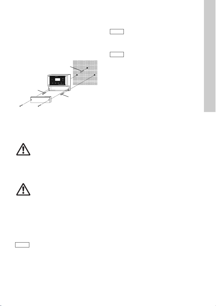
1. Drill three holes (8 mm) as shown in the
Caution
B
B
A
Caution
Note
diagram, and insert the supplied dowels.
2. Screw the screw (A) into the top centre dowel
until it projects by approximately 1 cm. See fig. 7.
3. Loosen the fastening screws of the front panel,
and remove the front panel.
4. Hang the instrument onto the screw (A).
5. Tighten the instrument with the two screws (B).
6. Mount the front panel of the enclosure.
Fig. 7 Mounting drawing
10. Commissioning / electrical
connections
Warning
Switch off the power supply before
installing!
Enclosure class IP65 is only guaranteed
with the front panel of the terminals
enclosure closed and with appropriate
cable glands or dummy caps.
Warning
Switch off the power supply before
connecting the power supply cable and the
relay contacts! For safety reasons, the
protective conductor must be connected
correctly!
Observe the local safety regulations!
Protect the cable connections and plugs
against corrosion and moisture.
Before connecting the power supply cable,
check that the supply voltage specified on
the nameplate corresponds to the local
conditions!
An incorrect supply voltage may destroy
the device!
To guarantee electromagnetic compatibility
(EMC), the input and current output cables
must be screened.
Connect the screening to the screen
ground on one side.
Refer to the wiring diagram! Route the
input, current output and power supply
cables in separate cable channels.
Enclosure class IP65 is only guaranteed if
the terminal cover is correctly sealed! Do
not damage the gasket on the terminal
cover!
The gasket on the terminal cover must be
positioned precisely!
Do not damage the gasket!
Unused terminals must remain open.
1. Remove the terminal cover on the front of the
device.
2. Use the appropriate cable feedthroughs and
tighten the screws carefully.
3. Connect the cables used to the terminals
according to the Conex
assignment.
4. Close the terminal cover again with correctly
positioned gasket.
TM03 6692 4506
®
DIA-1 terminal
English (GB)
15
Page 16

10.1 Terminals
15
17 19 21 23 25
27
29 31 33 35
3634323028262422201816
15 17 19 21 23 25 27 29 31 33 35
3634323028
262422201816
37 38 39 40 41 42
37 =
38 = M
15 17
19
21 23 25 27 29 31 33 35
3634323028262422201816
PAA
H
2
O
2
15 (wh)
16 (br)
17 - 22
23 - 30
32,34,36
810
7
9
12
N.C.
N.O
.
11 13
12 14
21/22 = Pt 100
19 = + H
2
O, 20 = – H
2
O
17/18 =
1
2
3
4
Cl
2
,ClO
2
,O
3
,
H
2
O
2
,PAA
T /
+
–
mA
pH, mV, F
–
mA
mA
mA
33/35
mA
mA
39 = B/R
40 = G/C
mA
+
–
+
–
+
–
+
–
41/42 =
+/–
mV
–
pH
F
1
4
1
4
P1
P2
P2
P1
1 3 5
2 4 6
1 3 5
2 4 6
+ -
+ -
115/120 V
230/240 V
24 V/DC
NLPE
NLPE
Cells / electrodes
External
input
Outputs
Sensors
cells
Alarm
Relays
Sensors
(water)
Controller stop
Outputs
External
input
24 V/DC
115/120 V
230/240 V
15 (white)
16 (brown)
English (GB)
10.1.1 Wall-mounted enclosure Conex® DIA-1
Fig. 8 Terminals of wall-mounted enclosure
TM03 6693 4506
16
Page 17

10.1.2 Control panel enclosure Conex
2/1
2/2
2/3
2/4
2
/1, 2/2
=
5/1 - 5/5
2/3 (+), 2/4 (–)
=
H
2
O
+
–
M B/R G/C
Pt 100
3/1 - 3/4
pH, mV, F
–
Cl
2
, ClO
2
,
O
3
,PAA,
H
2
O
2
pH, mV, F
–
3/1
3/2
3/3
3/4
4/1
4/2
4/3
4/4
7/1
7/2
7/3
N.C.
N.O.
1/1 (br), 1/2 (wh)
PAA
H
2
O
2
6/1
6/2
6/3
6/4
1
2
A 1/1 (br)
B 1/2 (wh)
PAA
H
2
O
2
A 2
/3 (+)
B 2 /4 (-)
H
2
O
1/11 1/13 4/1
1/12 1/14
4/3
4/2 4/4
3/1 3/3
3/2 3/4
B
A
1/11 -1/14
Pt 100
4/1 - 4/4
Conex DIA-1
5/1
5/2
5/3
5/4
5/5
5/1
5/2
5/3
5/4
5/5
1
2
3
4
T
mA
Cl
2
, ClO
2
,
O
3
,H
2
O
2
,
PAA
pH, mV, F
–
mA
+
–
4
1
1/1
1/2
1/3
1/4
1/5
1/6
1/7
1/8
1/9
1/10
1/11
1/12
1/13
1/14
8/1
8/2
8/3
PE
N
L
8/1
8/2
8/3
-
+
115/120 V
230/240 V
24 V/DC
Controller stop
(water)
Relays
Alarm
Connection to
Conex
®
DIA-1
Cells
(water)
Cells:
Outputs
External input
Sensor interface
Cells / electrodes
Cells
Electrodes
Jumper
DIP
off on
24 V/DC
1/2 (white)
Fig. 9 Terminals of control panel enclosure
®
DIA-1
English (GB)
5/1 - 5/5
TM03 6979 4506
17
Page 18

Legend of terminals
Note
Caution
+
-
DC
R
C
AC
English (GB)
Pos. Description
Relays Relay 1 + 2
Alarm relay
Alarm
– N.O.: normally open
– N.C.: normally closed
Pt100 Temperature sensor
H
O Sample-water deficiency sensor
2
Stop Controller stop
Outputs Current outputs [mA]
Cl2 (chlorine), ClO2 (chlorine
1
dioxide), O
(hydrogen peroxide) or PAA
(peracetic acid)
(ozone), H2O2
3
2 pH, mV (redox)
3 T: temperature
4 Continuous controller
Inputs External inputs [mA]
Electrodes
Measuring cells, electrodes and
single-rod measuring chains
M Measuring electrode
B/R Reference electrode
G/C Counter electrode
Earth
mV Redox electrode
®
Control panel enclosure Conex
• Conex
®
DIA-1: for installation in the control
DIA-1
panel.
• Sensor interface: for installation near the
sensors.
10.2 Power supply connection
1. Control panel enclosure: Plug the plug strip into
the corresponding terminal strip at the rear side
of the device. Ensure correct orientation.
2. Connect the protective earth conductor (PE) to
terminal 5 (wall-mounted enclosure) or
terminal 8/1 (control panel enclosure).
3. Connect the neutral conductor (N) (or the conductor with 24 V version) to terminal 3
(wall-mounted enclosure) or terminal 8/2 (control
panel enclosure).
4. Connect phase (L1) (or the + conductor with 24 V
version) to terminal 1 (wall-mounted enclosure)
or 8/3 (control panel enclosure).
Switch the device on and off by switching the power
supply on and off accordingly. The device itself is not
equipped with a separate on/off switch.
10.3 Relay outputs
The connection of the relay outputs
depends on the application and the final
control elements used. Therefore the
connections described below should only
be considered as guidelines.
With inductive loads (also relays and contactors),
interference suppression is necessary. If this is not
possible, protect the relay contacts using a
suppressor circuit as described below.
• With AC voltage:
Current up to Capacitor C Resistor R
60 mA 10 nF, 275 V 390 Ω, 2 W
70 mA 47 nF, 275 V 22 Ω, 2 W
150 mA 100 nF, 275 V 47 Ω, 2 W
1.0 A 220 nF, 275 V 47 Ω, 2 W
• With DC voltage: Connect the free-wheeling
diode in parallel to relay or contactor.
Provide the relay outputs with a
corresponding backup fuse!
Fig. 10 Suppressor circuit, DC/AC
TM03 7209 2813
18
Page 19

10.4 Current output
Caution
Note
Make sure that the polarity of the current
output is correct!
Maximum load: 500
The current output can be set to one of the two
standard ranges "0-20 mA" or "4-20 mA", or it can be
freely adjusted.
• Connect the screen to earth (PE) at one end.
Output 1: chlorine, chlorine dioxide, ozone,
hydrogen peroxide or peracetic acid
This current output shows the displayed measured
value as an analog current signal.
Use of current signal for measured values:
• as input signal for another indicator
• as input signal for an external controller.
1. Connect the + conductor to terminal 23
(wall-mounted enclosure) or terminal 1/3 (control
panel enclosure).
2. Connect the - conductor to terminal 24
(wall-mounted enclosure) or terminal 1/4 (control
panel enclosure).
Output 2: pH, redox
This current output shows the displayed measured
value as an analog current signal.
Use of current signal for measured values:
• as input signal for another indicator
• as input signal for an external controller.
1. Connect the + conductor to terminal 25
(wall-mounted enclosure) or terminal 1/5 (control
panel enclosure).
2. Connect the - conductor to terminal 26
(wall-mounted enclosure) or terminal 1/4 (control
panel enclosure).
Output 3: temperature
This current output shows the temperature measured
by the optional temperature sensor.
Use of current signal for measured values:
• as input signal for another indicator.
1. Connect the + conductor to terminal 27
(wall-mounted enclosure) or terminal 1/6 (control
panel enclosure).
2. Connect the - conductor to terminal 28
(wall-mounted enclosure) or terminal 1/7 (control
panel enclosure).
Ω
.
Output 4: continuous control
This current output shows the calculated actuating
variable signal as an analog current signal.
Use of actuating variable signal:
• as input signal for a continuous final control
element.
1. Connect the + conductor to terminal 29
(wall-mounted enclosure) or terminal 1/8 (control
panel enclosure).
2. Connect the - conductor to terminal 30
(wall-mounted enclosure) or terminal 1/7 (control
panel enclosure).
10.5 Connections of controller stop,
sample-water sensor and temperature
sensor
Connecting the controller stop
1. Connect the + conductor to terminal 17
(wall-mounted enclosure) or terminal 2/1 (control
panel enclosure).
2. Connect the - conductor to terminal 18
(wall-mounted enclosure) or terminal 2/2 (control
panel enclosure).
Connecting the sample-water sensor
Cable colours and marking: See connections of
measuring-cell types
AQC-D1/-D11/AQC-D2/-D12/AQC-D3/-D13.
1. Connect the + conductor to terminal 19
(wall-mounted enclosure) or terminal 2/3 (control
panel enclosure).
2. Connect the - conductor to terminal 20
(wall-mounted enclosure) or terminal 2/4 (control
panel enclosure).
When using measuring cell AQC-D2/-D12,
the water sensor must always be
connected and activated!
Connecting the Pt100 temperature sensor
1. Connect the + conductor to terminal 21
(wall-mounted enclosure) or terminal 1/11
(control panel enclosure).
2. Connect the - conductor to terminal 22
(wall-mounted enclosure) or terminal 1/12
(control panel enclosure).
English (GB)
19
Page 20

10.6 Connection of measuring cells
1
2
2
1:
Standard
7
5
1
37
38 39
40
41 42
6
12
4
1
15 171921 23 25 27 29 31 33 35
3634323028262422201816
9, 10, 11
8
2
3
4
21
19
2220
4
12
11
1
1
38 40
39
9
8
10
7
10
9
1
6
2
37 38
39
40
8
21
19
2220
4
12
11
1
1
7
10
9
1
6
2
37 38
39
40
8
21
19
2220
2
12
11
COM
11
1
NC
12
15 17 19 21 23 25 27 29 31 33 35
3634323028262422201816
37 38 39 40 41 42
21
14 15
English (GB)
Jumper setting
• All cell types: position 1 (standard).
Fig. 11 Jumper setting
10.6.1 Connection of wall-mounted enclosure
Conex
®
DIA-1
Fig. 12 Connection to measuring cells
AQC-D1/AQC-D2/AQC-D3
TM03 6696 4506
TM04 8643 4112TM04 8644 4112TM03 6966 4112
Fig. 14 Connection to measuring cell
AQC-D12
TM03 5872 4112TM04 8642 4112
Fig. 13 Connection to measuring cell
AQC-D11
20
Fig. 15 Connection to measuring cell
Fig. 16 Connection to measuring cells
AQC-D13
PAA (peracetic acid) / HP (peroxide)
Page 21

Fig. 17 Connection to single-rod measuring
37 38 39 40 41 42
7
13
+-
1/111/
13
4/
1
1/121/
14
4/
3
4/
2
4/
4
3/13/
3
3/23/
4
B
A
1
4
Conex
2/
3
2/
4
+
-
12
MB/RG/C
7
1
6
Pt 100
2
5
8
9, 10, 11
3
4
Sensor interface
4
11
1
Pt 100
9
8
10
1/111/
13
4/
1
1/121/
14
4/
3
4/
2
4/
4
3/13/
3
3/23/
4
B
A
1
4
Conex
2/
3
2/
4
+
-
12
G/CM
B/R
Sensor interface
7
10
9
1
6
2
8
4
11
1
1/111/
13
4/
1
1/121/
14
4/
3
4/
2
4/
4
3/13/
3
3/23/
4
B
A
1
4
Conex
2/
3
2/
4
+
-
12
Pt 100G/CM
B/R
Sensor interface
chains for pH, redox
Pos. Description
1Brown
2White
3Black
4Blue
5 Screen
6 Outer conductor (screen)
7 Inner conductor
8 Reference electrode
9 Measuring electrode
10 Counter electrode
11 Pt100 temperature sensor
12 Water sensor
13 Outer conductor
14 Yellow
15 Green
10.6.2 Connection of control panel enclosure
Conex
®
DIA-1
TM03 6967 4506
Fig. 19 Connection to measuring cell
AQC-D11
English (GB)
TM04 8645 4112TM04 8646 4112
Fig. 18 Connection to measuring cells
AQC-D1/AQC-D2/AQC-D3
Fig. 20 Connection to measuring cell
AQC-D12
TM03 5871 4212
21
Page 22

English (GB)
7
10
9
1
6
2
8
2111
1/111/
13
4/
1
1/121/
14
4/
3
4/
2
4/
4
3/13/
3
3/23/
4
B
A
Conex
2/
3
2/
4
+
-
12
Pt 100G/CM
B/R
COM
11
NC
12
Sensor interface
MB/R
G/C
1/11 1/ 13 4/1
1/12 1/14
4/3
4/2 4/ 4
3/1 3/3
3/2 3/4
B
A
1/1
1/2
+
-
21
1415
+-
7
13
Fig. 21 Connection to measuring cell
AQC-D13
Pos. Description
1Brown
2White
3Black
4Blue
5 Screen
6 Outer conductor (screen)
7 Inner conductor
8 Reference electrode
9 Measuring electrode
10 Counter electrode
11 Pt100 temperature sensor
12 Water sensor
13 Outer conductor
14 Yellow
TM04 8647 4112TM03 6968 4112
15 Green
Peculiarities for the connection at the control
panel enclosure of Conex
1. First connect the measuring cells, the single-rod
measuring chains and the sensors to the sensor
interface.
2. Secondly, connect the sensor interface to the
Conex
®
DIA-1.
®
DIA-1
Fig. 22 Connection to measuring cells
Fig. 23 Connection to single-rod measuring
22
PAA (peracetic acid) / HP (peroxide)
chains for pH, redox
TM03 6969 4506
Page 23

Connecting the sensor interface to the
Note
OFF
On
DIP
2
3
4
1
ClO2,O
3
Cl
2
®
DIA-1 (see back side of device)
Conex
• Measuring cells
AQC-D1/-D11/AQC-D2/-D12/AQC-D3/-D13,
PAA (peracetic acid) / HP (peroxide)
Connect terminals 4/1 to 4/14 of the sensor
interface to the corresponding terminals of the
®
DIA-1.
Conex
• Measuring cells HP (peroxide) /
PAA (peracetic acid)
In addition, connect terminal A to terminal 1/1
and terminal B to terminal 1/2 of the
®
DIA-1.
Conex
• Single-rod measuring chains
• (pH, redox)
Connect terminals 3/1 to 3/4 of the sensor
interface to the corresponding terminals of the
®
DIA-1.
Conex
• Sample-water deficiency sensor
Connect terminal A to terminal 2/3 and terminal B
to terminal 2/4 of the Conex
®
DIA-1.
When using measuring cell AQC-D2/-D12,
the water sensor must always be
connected and activated!
DIP switch
• If necessary, set the DIP switch for the desired
measured value to "On" (move the switch to the
right, top switch 1 is not used).
English (GB)
Fig. 24 DIP switch
TM03 6699 4506
23
Page 24

11. Operation
1
86
54
3
7
781
6
5
43
2
2
1
86
54
3
7
781
6
5
43
2
2
English (GB)
11.1 Control and display elements
TM03 6700 4506
Fig. 25 Wall-mounted enclosure and control panel enclosure
Pos. Description
Control elements
Red alarm LED
1
• Flashes in case of faults or incorrect
entries.
2 Display
Operating buttons
[OK] button
3
• Enters the selected menu.
• Confirms the selected line or value.
[Down] button
• Moves one line downward (the selected
4
line is displayed inversely).
• Decreases values.
[Up] button
• Moves one line upward (the selected line
5
is displayed inversely).
• Increases values.
[Esc] button
• Returns to the previous menu.
6
– The data which were entered last are
not changed.
Function buttons with yellow LED
[Cal] button
• Switches between calibration and
measuring mode.
7
– In calibration mode, the corresponding
LED illuminates.
[Man] button
• Switches between automatic and manual
8
modes.
– In manual mode, the corresponding
LED illuminates.
24
Page 25

11.2 Display elements during initial
Note
chlorine
0.43 mg / l
5.20 pH
22 °C
c
cc
commissioning
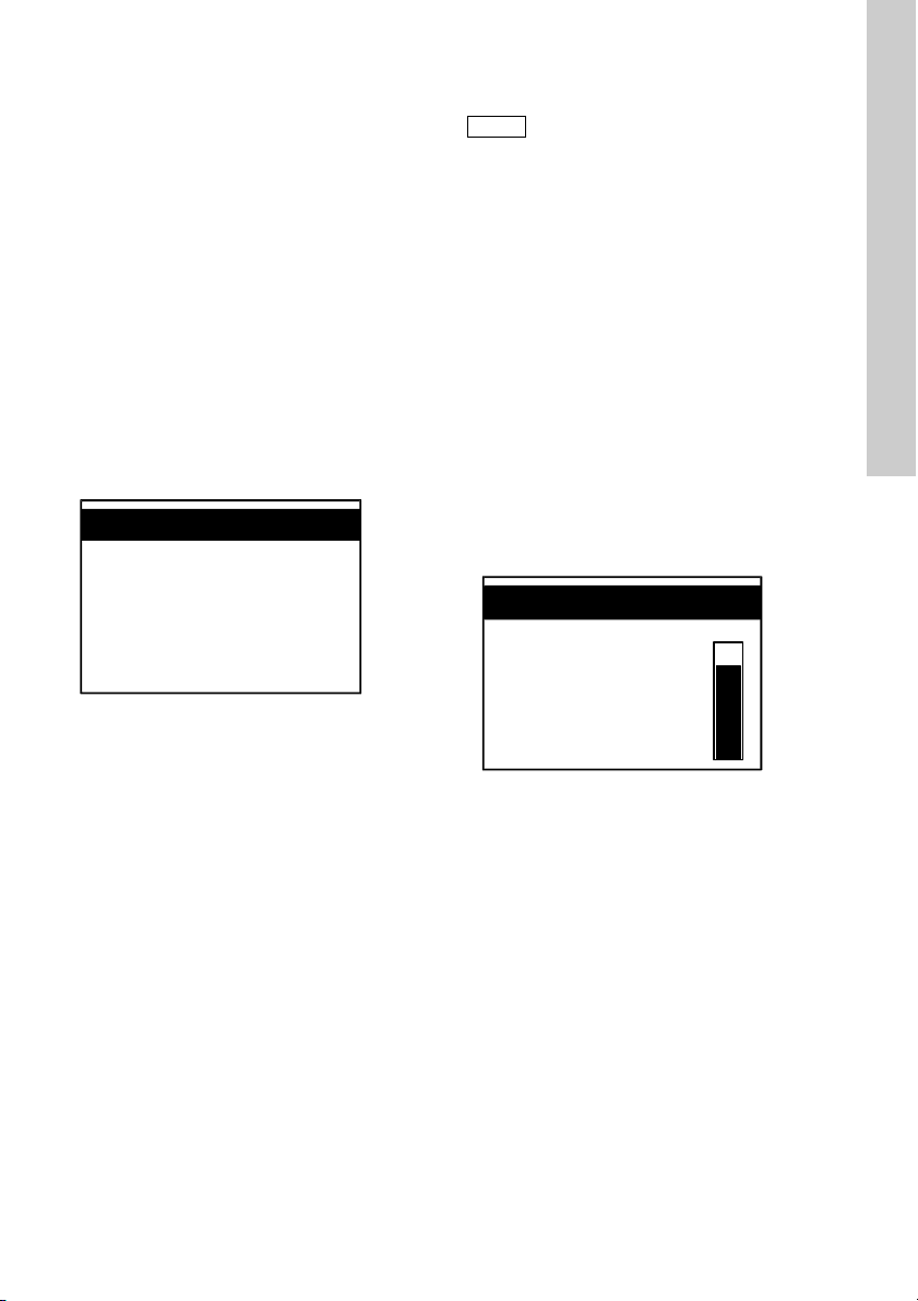
When connected to the power supply on the device’s
initial commissioning and following the start-up
indication, the display shows the "Sprache/language"
menu.
Language/Langue...
Deutsch
English
Français
Nederlands
• The word "language" in the header is displayed in
all available languages successively at intervals
of approximately one second.
Start the Conex
operating language:
1. Select the desired language using the [Up] and
[Down] buttons.
– The selected language is displayed inversely
(white letters on black background).
2. Press [OK] to confirm.
The translations for the words "setup" and
"language" into the currently available languages
are:
Deutsch
Hauptmenü Grundeinstellung Sprache
English
main menu setup language
Français
Menu principal Paramétrage Langue
Nederlands
hoofdmenu basisinstelling taal
Español
Menu principal Ajuste básico Idioma
Italiano
Menu principale programm. fond. lingua
Português
Menu principal Posição inicial Língua
Pусский
главное меню станд. настройка язык
Polski
manu główne ustawienia język
®
DIA-1 by selecting the desired
The selected language is stored and will
remain the operating language when the
device is rebooted. If necessary, the
operating language can be changed in the
"language" submenu in the "setup" menu.
See section 11.5 Setup.
chlorine
0.43 mg/l
• After selecting and confirming the operating
language by pressing [OK] during initial
commissioning, the display shows "chlorine" as
the value to be measured.
– On subsequent start-ups, the display will show
the measured value selected the previous
time.
• On upward or downward violation of the selected
measuring range, the display will show the upper
or lower limit and flash.
See sections 8.4 Measuring ranges and
11.5.4 Setting the measuring ranges for chlorine,
chlorine dioxide, ozone, peroxide, peracetic acid,
pH, redox.
English (GB)
TM03 6704 4506
25
Page 26

11.3 Software overview
Note
English (GB)
Provided that the code numbers for access
right have been set, some menus (and
submenus) as well as the functions Cal
and Man are protected against
unauthorised access. The protected
menus are marked with "C" (calibration
rights) or "F" (full rights).
Main menus
• Controller, see section Controller.
• Alarm, see section Alarm.
• Service, see section Service.
• Setup, see section Setup.
Function buttons
• Cal, see section Calibration function.
• Man, see section Manual operation.
Controller
"F" (full rights)
Setting the parameters
• Relay 1/2
– internal/external setpoint
– controller parameters.
• Continuous controller
– internal/external setpoint
– controller parameters.
Alarm
"F" (full rights)
• Alarm settings
– alarm values (switching points)
– effective direction
– hysteresis
– alarm delay.
• Dosing time monitoring
– maximum dosing time (at constant dosing flow
level of 100 %).
Service
• Calibration logbook
– the last ten calibrations.
• Calling up the controller settings
• Test of functioning of current outputs
• Test of functioning of relays
• Test of functioning of display.
Setup
"F" (full rights)
• Selecting language
• Parameters: selecting measured values
• Selecting measuring cell
• Selecting measuring range
• Configuration of controllers
• Switching on/off water sensor
• Time setting
• Code function
• Display contrast
• Calling up factory settings
• Current output: assignment of current outputs to
measuring ranges
• Calling up program version.
Calibration function
"C" (calibration rights)
• Calibration of selected parameters
– chlorine, chlorine dioxide, ozone, peroxide,
peracetic acid, pH.
Manual operation
"C" (calibration rights)
• Running the configured controllers manually.
26
Page 27

11.4 Main menu
Note
1. Switch to "main menu" by pressing [OK] or, if
necessary, by pressing [Esc] several times.
Options in "main menu"
main menu
controller
alarm
service
setup
• "controller"
In this submenu, a controller can be
parameterised. This option will only be displayed
if a type of controller has been selected in the
"setup" menu.
• "alarm"
In this submenu, the measured value is
compared with the permitted value, and an alarm
is triggered, if necessary.
• "service"
Diagnosis submenu. The measured values and
the last ten alterations of calibration data can be
viewed. In this mode, values cannot be altered.
If measuring cell AQC-D2/-D12 is selected, the
data of the water sensor can be viewed.
• "setup"
In this submenu, the settings for language,
parameters, measuring ranges, controllers, etc.
can be adjusted.
Selecting the functions "calibration" and
"manual operation"
See the buttons [Cal] and [Man] to the right of the
display.
• Calibration: Press [Cal] to switch to the
calibration menu (the yellow LED illuminates).
• Manual operation: Press [Man] to switch to
manual operation (the yellow LED illuminates).
Switching to manual operation is only
possible if a controller type has been
selected in the "setup" menu.
The functions "Cal" and "Man" can only be
accessed by persons with calibration rights
or full rights.
English (GB)
27
Page 28

11.5 Setup
setup
parameters
chlorine
pH
pH internal
(electrode)
on
pH compensation
chlorine on/off
temp. meas.
on/off
temp. comp. chlorine
on/off
temp. comp. pH
on/off
pH external
pH compensation
chlorine on/off
temp. meas.
on/off
temp. comp. chlorin e
on/off
pH
off
temp. meas.
on/off
temp. comp. chlorine
on/off
chlorine dioxide,
ozone
temp. meas.
on/off
temp.
comp. on/off
temp.
comp. on/off
pH
redox
temp. meas.
on/off
temp. meas.
on/off
on
on
on
on
on
on
on
on
on
English (GB)
All standard settings of the device can be defined in
the "setup" menu. During initial commissioning, basic
functions are configured which after that should only
be altered rarely or even not at all.
11.5.1 Selection of measured values for chlorine, chlorine dioxide, ozone, peroxide, peracetic acid, pH,
redox
The "setup" menu can only be accessed by persons
having full rights.
See section 11.5.7 Code function.
Enter the code number.
Fig. 26 Selection of measured value in "parameter" menu
TM03 6707 4506
28
Page 29
1. Select the line "parameter" using the [Up] and
chlorine
0.43 mg/l
5.20 pH
22 °C
c
c
Note
chlorine
0.43 mg/l
[Down] buttons, and press [OK] to switch to the
corresponding menu.
2. Select the line(s) indicating the values to be
measured (parameters) using the [Up] and
[Down] buttons.
11.5.2 pH and temperature compensation
pH compensation with chlorine measurement
The dissociation of hypochlorous acid (HOCl) into
the hypochlorit-anion (OCl
(loss of sensitivity) of the sensor for chlorine
measuring.
Using a mathematical compensation function, this
loss of sensitivity can be eliminated.
Temperature compensation
Using a compensation function, the influence of
temperature on the measurement can be eliminated
mathematically.
Control field for pH value, pH compensation,
temperature and temperature compensation in
the display of measured value
Fig. 27 Chlorine measurement with pH and
• Press [Esc] once or twice to change to the
See sections 11.2 Display elements during initial
commissioning and 11.6.5 Controller control fields
on the display.
In addition to the current measured value, the
current pH value and the temperature of the sample
water are indicated as well.
With activated pH compensation or temperature
compensation, the letter "c" for "compensation" is
displayed at the end of the line.
With deactivated temperature measurement, the
water temperature for compensation should be
entered manually after calibration. See section
11.9.1 Calibrating the pH value.
temperature compensation
display with the measured value.
-
) leads to a loss of slope
11.5.3 Selection of measuring cell
The "measuring cell" submenu is shown
only if the measured values chlorine,
chlorine dioxide or ozone were selected
during the parameterisation.
Names of the measuring cells contained in the
software
•AQC-D1/-D11
• AQC-D2/-D12
• AQC-D3/-D13
The measuring cell that corresponds to the selected
measured value can be selected:
• AQC-D1/-D11/AQC-D2/-D12/AQC-D3/-D13 with
chlorine, chlorine dioxide or ozone
The measuring cell PAA/HP is selected automatically
if "peracetic acid/peroxide" is selected as the
measured value.
Monitoring the cleaning motor (measuring cells
AQC-D1/-D11)
Having selected measuring cell type AQC-D1/-D11,
press [OK] to get to the "cleaning motor" submenu.
1. Switch the monitoring of the cleaning motor
on/off.
Measuring cell AQC-D2/-D12/-D3/-D13 selected
TM03 6703 4506
Fig. 28 Chlorine measurement with
A black bar on the display indicates the actual data
of the water sensor.
See the installation and operating instructions for the
potentiostatic measuring cell
AQC-D2/-D12/-D3/-D13.
AQC-D2/-D12/-D3/-D13
English (GB)
TM03 6708 4506
29
Page 30

11.5.4 Setting the measuring ranges for chlorine,
Note
Caution
01 : 18 : 40 pm
time
time set
English (GB)
chlorine dioxide, ozone, peroxide,
peracetic acid, pH, redox
In the "measuring ranges" menu, the corresponding
measuring ranges are assigned to the measured
values which have been selected in the "parameters"
menu.
• In the "measuring ranges" menu, the following
options are available:
– Between two (with redox) and six (chlorine)
standard measuring ranges. See section
8.4 Measuring ranges.
– "others": Using the [Up] and [Down] buttons,
the operator can set the lower and the upper
limit of the measuring range to any value
within the widest standard measuring range.
• The measuring ranges for temperature can be
defined in °C (Celsius) or in °F (Fahrenheit).
The "temperature" submenu is only shown
if the temperature measurement has been
switched on in the "parameter" menu, or if
parameter pH has been selected.
11.5.5 Water sensor
In the "wat. def. sensor" menu, the water sensor can
be switched on/off.
In the event of sample-water deficiency, the following
will occur:
• The malfunction-indicating relay is activated, and
the alarm message "fault water sensor" is
triggered.
• With devices with control functions, the actuators
are switched to passive or closed.
The water sensor must be switched on for
the measuring cell AQC-D2/-D12!
11.5.6 Setting the current time (date/time/summer time)
1. Switch from the "setup" menu to the "date/time"
menu.
Fig. 29 Time setting
2. Set the device to the current time in the "time set"
menu in the format hh.mm.ss.
– Press [OK] to switch to the next number field.
The number field which is currently activated
flashes.
– Alter the settings by pressing the [Up] and
[Down] buttons.
– Pressing the buttons continuously makes the
adjustment dynamically faster.
3. Set the device to the current date in the "date"
menu in the format mm.dd.yyyy with English as
operating language or the format dd.mm.yyyy for
all other languages similarly to the adjustment of
time. The corresponding day of the week
(Mo...Su) is displayed automatically.
4. If necessary, enter the beginning and end date of
the summer time, the kind of time shift and the
number of hours of the time shift.
11.5.7 Code function
The code function is designed to protect the device
from unauthorised access.
Entering the four-digit code number and
changing it
1. Select the line "code function" in the "setup"
menu using the [Up] and [Down] buttons, and
press [OK] to switch to the corresponding menu.
There are two types of access rights:
Calibration rights: The owner of calibration rights
has access to the calibration menu and to manual
operation.
The owner of calibration rights may do the following:
• alter calibration data
• operate control relays manually.
Full rights: The owner of full rights has full access to
all settings including calibration data.
TM03 6709 4506
30
Page 31

The owner of full rights may do the following:
Note
Note
Note
Caution
Caution
• alter calibration data
•alter setup
• parameterise the controller
• alter alarm settings
• run the device manually.
cal right
code 0000
old code
2. Select the desired type of access rights, and
press [OK] to get to the corresponding menu.
3. If an old code exists, confirm the old code
number first (on first use, confirm code 0000).
4. Select "change".
5. Enter the old code in the submenu (see the
comment line at the bottom of the display) using
the [Up] and [Down] buttons, and press [OK] to
confirm and switch to the query "new code" (see
the comment line at the bottom of the display).
6. Enter a new four-digit code number using the
[Up] and [Down] buttons. Press [OK] to confirm.
7. Access rights can be cancelled by deleting the
corresponding code number in the "delete"
submenu.
• Entering a valid four-digit code number gives the
operator access to the corresponding functions
for a limited time of 60 minutes.
• If no code was entered previously, the desired
menu can be accessed without restrictions.
The code number 0000 will not be displayed / the
operator will not be asked to enter it.
If a wrong code is entered, access to the
corresponding menus is denied.
An error message is triggered (duration:
five seconds), and the device will return to
"main menu".
11.5.8 Reset function
• Entering the code number "1998" deletes all
previously entered code numbers.
• All prior access codes are deleted and reset to
"0000".
11.5.9 Adjusting display contrast
In the "display" menu, the contrast of the display can
be adjusted.
1. Switch from the "setup" menu to the "display"
menu using the [Up] and [Down] buttons, and
press [OK] to confirm.
If the contrast setting is too high, it may not
be possible to read the display. Hold down
the [Down] button until the contrast setting
is low enough to be read again.
11.5.10 Saving / accessing user settings
In the "factory setting" submenu, the current device
setting can be saved so that it can be reactivated
later, or a saved setting can be activated.
• Setup
- Save setup: Saves all current device settings
from the menus (not just the "setup" settings).
- Activate setup: Resets the device to the last
saved setup.
In this menu, save your device settings
once you have set all the values in the
"setup", "controller" and "alarm" menus.
You can then activate them again at any
time (even after a factory reset)!
11.5.11 Factory setting reset
In the "factory setting" submenu, the Conex
can also be reset to the factory setting using
®
DIA-1
code 6742.
Only use this function in an emergency. All
device settings are lost and must be
re-entered!
Do not disconnect the device from the
power supply during the reset!
®
Resetting the Conex
DIA-1 to the factory setting
• Reset
- Code: 0000 is displayed.
- Set code 6742 using the [Up] and [Down]
buttons, and press [OK] to confirm.
The device is now returned to the original factory
setting.
Before subsequent start-up:
Check all parameters and set the device
again according to your application!
English (GB)
31
Page 32

General factory settings
English (GB)
• Language: The Conex
language input. The languages "Deutsch/English
Français...." are indicated alternately.
®
DIA-1 is waiting for
• Summer time: off.
• Code numbers: 0000 calibration rights, 0000 full
rights.
Parameter settings
• Current outputs: 0-20 mA.
• With free adjustment of limits:
– lower limit = lower end of measuring range
– upper limit = upper end of measuring range.
• Alarm values: alarm off.
• Dosing time monitoring: off.
Cl
2
ClO2/O
3
H2O
2
PAA
Measuring range [mg/l] 0.00 - 2.00 0.00 - 1.00 0-100 0-100
Measuring cell AQC-D1/-D11/-D3/-D13/-D2/-D12
HP
(peroxide)
PAA
(peracetic acid)
pH measurement off - - -
Monitoring cleaning
motor
off off - -
Water deficiency sensor off off off off
Current output 0-20 mA 0-20 mA 0-20 mA 0-20 mA
alarm
acknowledgment
alarm
acknowledgment
alarm
acknowledgment
alarm
acknowledgment
pH Redox
Measuring range [mg/l] 2.00 - 12.00 0-1000
Sensor slope [mV]/[pH] -58 [mV]/[pH] -
Asymmetry potential 0-
Calibration temperature [°C] 25 25
Water deficiency sensor off off
Current output 0-20 mA 0-20 mA
alarm acknowledgment alarm acknowledgment
Factory settings of controllers
• Switching controller:
– output 1: off
– limit contact / output 2: off
• Two-position controller:
– switching direction or control direction output 1:
downward violation
– switching direction or control direction output 2:
upward violation
• Controller behaviour with all controllers: PI
• Current output continuous controller: 0-20 mA.
32
Page 33

11.5.12 Current outputs
Note
Make sure that the selected output
corresponds with the selected parameter.
In the "current output" menu, the operator can assign
the selected values to the current outputs and then
assign the current outputs to the selected measuring
ranges.
In the "current output" menu, the selected
parameters are listed in the following order:
current output
2. Enter the associated lower current limit using the
[Up] button. Press [OK] to confirm.
– Another query for the upper limit of the
measuring range that reads "20.00 mg/l" is
displayed.
chlorine
0.20 mg/l = 0 mA
15.00 mg/l = 20 mA
English (GB)
chlorine
pH
temperature
• Output 1: Cl
, ClO2, O3, H2O2, PAA
2
• Output 2: pH, redox
• Output 3: temperature
• Output 4: continuous controller.
Assignment of the current outputs to the
measuring range
(example: chlorine measurement)
There are two standard ranges, "0-20 mA" and
"4-20 mA", which can be assigned to the current
outputs. They are assigned to the measuring range
linearly.
For the current outputs 1 to 3 the lower and upper
limits can be defined freely within the interval
0-20 mA.
chlorine
0-20 mA
4-20 mA
others
1. For free adjustment, select the line "others" in the
corresponding submenu using the [Up] and
[Down] buttons. Press [OK] to confirm.
– In the same line, "= 0 mA" is displayed.
chlorine
3. Enter the upper limit of the measuring range
using the [Down] button. Press [OK] to confirm.
– In the same line, "= 20 mA" is displayed.
4. Enter the associated upper current limit using the
[Down] button. Press [OK] to confirm and return
to the "current output" menu.
11.5.13 Program version
setup
V0.20.1 19991028
program version
In case problems make it necessary to contact our
service department, the "program version" menu
enables the operator to easily identify the software
components of the actual device.
• Version: for example v0.20.1.
• Last update: yyyymmdd.
0.20 mg/l = 0 mA
33
Page 34

11.6 Selection, configuration and
setup
controller
switching
ctrl.
limit/2-p
osition
relay
1/2
off
limit
contact
downward
viol.
upward
violation
inter-pul
se ctrl.
downward
control
upward
control
P
PI
PID
ext./ int.
setpoint
pulse
freq.
ctrl.
adjustment, see
interpulse controller
cont.
controller
3-pos.
ctrl.
off
off
adjustment, see
interpulse controller
adjustment, see
interpulse controller
English (GB)
parameterisation of the controller
It takes two steps to set up the controller:
• First: selection and configuration of the controller
type in the "setup" menu, "controller" submenu.
• Secondly: parameterisation of the selected
controller type in "main menu", "controller"
submenu.
11.6.1 Selection and configuration of the controller
Fig. 30 Selection and configuration of the controller
• In the "setup" menu, select the line "controller"
using the [Up] and [Down] buttons, and press
[OK] to switch to the "controller" menu.
34
TM03 6711 4506
Page 35

11.6.2 Selection and configuration of a switching
controller
1. Select the line "switching ctrl." using the [Up] and
[Down] buttons, and press [OK] to change to the
"switching ctrl." menu.
2. Select the line "limit/2-position" using the [Up]
and [Down] buttons.
3. Press [OK] to jump to the "relay 1" menu
automatically.
4. Using the [Up] and [Down] buttons, select one of
the following options:
– off
– limit contact
– interpulse controller (2-position)
– pulse frequency controller (2-position).
If a limit contact/two-position controller has been
selected, another limit contact/two-position controller
may be selected. An additional three-position
controller cannot be selected.
– After the configuration of the first two-position
controller/limit contact (relay 1) has been
completed, press [OK] to jump to the "relay 2"
menu.
If a three-position step controller has been selected,
no additional limit contact or two-position controller
can be selected.
Two-position and three-position step controllers:
As regards controller behaviour, one of the following
types of control can be selected:
• P: proportional controller (not with three-position
controller)
• PI: proportional-plus-integral controller
• PID: proportional-plus-integral-plus-derivative
controller (not with three-position controller).
As regards the setpoint, the following applies:
• With selected internal setpoint, adjustments
within the measuring range are possible.
• With externally selected setpoint, the operator
can choose between the standard current outputs
0-20 mA and 4-20 mA.
11.6.3 Selection and configuration of the continuous controller
The continuous controller can always be used.
1. Select the line "cont. controller" from the
"controller" menu using the [Up] and [Down]
buttons, and press [OK] to switch to the
"cont. controller" menu.
2. The control direction can - similarly to
two-position controllers - be set to either upward
control (downward violation of setpoint) or
downward control (upward violation of setpoint).
See section 11.6.2 Selection and configuration of
a switching controller.
3. As regards controller behaviour, either of the
controller types P, PI, PID can be selected.
See section 11.6.2 Selection and configuration of
a switching controller.
• As regards the setpoint, the following applies:
– With selected internal setpoint, adjustments
within the measuring range are possible.
– With externally selected setpoint, the operator
can select between the standard current
outputs 0-20 mA and 4-20 mA.
English (GB)
35
Page 36

11.6.4 Setting the controller parameters
Note
adjustments, see above and section 8.3
adjustments, see above and section 8.2
controller
main menu
i.e.
interpulse
control
relay 1 setpoint
setpoint
external
setpoint
internal
0-20 mA / 4-20 mA
chlorine 0.00-20.00 mg/l
pH 0-14.00 pH
0.0 to 3000.0 %
prop. band XP
reset time TN
deriv. action TV
int.pulse period
min. switch-on
constant load
max. dosing flow
adaptation
1 to 3000 s
1 to 1000 s
1 to 100 s
0.1 to 10.0 s
0 to 50 %
0 to 100 %
start
stop
adapt. result
cont.
controller
relay 2
English (GB)
1. Select a controller in the "setup" menu and
configure it.
See section 11.6 Selection, configuration and
parameterisation of the controller.
2. Select the line "controller" in "main menu" using
the [Up] and [Down] buttons, and press [OK] to
switch to the "controller" menu.
See section 11.4 Main menu.
The "controller" option in "main menu" is
only available if a controller has been
selected in the "setup" menu!
Example:
Configured limit contact or two-position
controller and activated continuous
controller.
Fig. 31 Setting the controller parameters
The options available in the "controller" submenu
(main menu) correspond to the configuration made in
the "setup" menu.
1. Use the [Up] and [Down] buttons to change
internal setpoints within the selected measuring
range.
See section 8.4 Measuring ranges.
36
2. Select the displayed controller parameters using
the [Up] and [Down] buttons, press [OK] to switch
to the desired submenu, and use the [Up] and
[Down] buttons to adjust the setpoints as needed
within the permitted ranges.
See section 8.3.3 Controller functions.
TM03 6712 4506
Page 37

11.6.5 Controller control fields on the display
12
chlorine
0.43 mg/l
5.20 pH
22 °C
c
c
12
continuous
controller
relay 2
relay 1
external setpoint
1
1
• The control fields for relays 1 and 2 are displayed
if a limit contact / two-position controller has been
configured:
Unfilled field for relay off:
Fig. 32 Chlorine measurement with pH and
1. Press [Esc] once or twice to switch to the display
See sections 11.2 Display elements during initial
commissioning and 11.5.2 pH and temperature
compensation.
The control fields shown on the display "measured
value" correspond to the configured controller.
• The control field ">" will only be displayed if an
temperature compensation
"measured value".
external setpoint has been defined.
Depending on the selected standard range
(0-20 mA or 4-20 mA) and the defined setpoint
level, it is displayed as not filled, partly filled or
completely filled (displayed inversely).
Not filled (at 0 or 4 mA):
Filled field (displayed inversely) for relay on:
TM03 6713 4506TM03 6714 4506
• The control field for the continuous controller is
displayed if a continuous controller has been
configured. Depending on the set dosing flow, it
is displayed as empty or as filled by a black bar
that indicates the current dosing flow in relation
to the system’s maximum dosing flow.
Example:
0 %:
50 %:
100 %:
English (GB)
Partly filled, for example setpoint 4 mA
(standard range 0-20 mA):
Completely filled, for example setpoint 20 mA
(standard range 0(4) to 20 mA):
37
Page 38

11.6.6 Adaptation
Note
chlorine
0.43 mg/l
adaptation
English (GB)
An adaptation can be started to simplify the setting of
the controller parameters.
The adaptation is only available for PI and PID
controllers.
1. Start adaptation in the "controller" menu (main
menu) under "adaptation" by pressing "start".
Fig. 33 Chlorine measurement with adaptation
2. Return to the display "measured value"
• The configured controllers can only be adapted
• On upward control, the measuring value has to
• On downward control, the measuring value has
In case of a fault, the message "Start conditions
false" is shown directly after the start.
3. The message "adaption abortive" is shown after
4. Press [OK] or [Esc] to quit. The determined
5. If the adaptation was not successful, the
The adaptation may be aborted in the following
cases:
• If an error message was shown during the
• If the controller is set to manual operation.
• If the standstill time was more than one hour.
• If the total measuring time was more than two
In case of an additional modification of the setpoint,
the controller settings will be automatically
compensated.
38
of continuous controller
automatically. A black bar on the display
indicates the adaptation process. The LED next
to the [Man] button flashes during the whole
adaptation. A progress bar shows the
advancement of the adaptation.
separately.
be more than 20 % below the setpoint.
to be more than 20 % above the setpoint.
ending the adaptation.
controller settings are automatically adapted by
the parameterisation of the controller. They are
displayed in the adaptation menu under
"adapt. result".
message "adaption abortive" is shown.
Press [OK] or [Esc] to quit.
adaptation.
hours.
With selected temperature / pH / redox
measurement, the temperature / pH /
redox value and their compensations will
not be displayed during the adaptation.
TM03 6715 4506
Page 39

11.7 "Alarm" menu
alarm
main menu
alarm values alarm off
alarm on
alarm value 1
(switching point1)
alarm
downward
viol.
upward
violation
downward
viol.
upward
violation
alarm value 2
(switching point2)
hysteresis
alarm delay
Note
With the help of the alarm function, the measured
value can be monitored and compared with the
permitted range.
If the measured value exceeds the limits of the
measuring range, an alarm is triggered.
• The alarm relay is activated after the selected
alarm delay time.
• When the cause of the alarm has been removed,
the relay is deactivated immediately (without
delay).
English (GB)
Fig. 34 "Alarm" in "main menu"
1. Select the line "alarm" in "main menu" using the
[Up] and [Down] buttons.
2. Press [OK] to switch to the "alarm" menu.
Two functions are available there:
alarm
alarm values
dos. time monit.
• alarm values: If the measured value exceeds the
permitted range, the alarm relay is activated and
an alarm message is triggered. The red alarm
LED starts flashing.
TM03 6716 4506
• dos. time monit.: If the dosing flow constantly
remains at 100 % during a selected maximum
dosing time, the alarm relay is activated and an
alarm message is triggered. The red alarm LED
starts flashing.
The dosing time monitoring is not activated
for three-position controllers!
39
Page 40

Setting the alarm values
English (GB)
1. Select the line "alarm values" using the [Up] and
[Down] buttons. Press [OK] to switch to the
"alarm on/alarm off" submenu.
– If "alarm off" is selected, the device will return
to the "alarm" menu if [OK] is pressed.
2. Press [OK] to switch to the "alarm on/alarm off"
submenu.
Setting the upper and lower switching point
(limits)
1. Select the line "alarm value 1" or "alarm value 2".
Press [OK] to confirm and switch to the desired
menu.
alarm value 1
0.00 mg/l
switching point1
2. Set switching points between 0 and the upper
limit of the measuring range defined earlier using
the [Up] and [Down] buttons (in the unit of the
measured value, the resolution depends on the
selected measuring value and measuring range).
See section 8.4 Measuring ranges.
3. Press [OK] to switch to the "eff. direction" menu.
Options: alarm message in the event of
upward/downward violation of the selected switching
point.
4. Select the desired line using the [Up] and [Down]
buttons.
5. Press [OK] to return to the "alarm values" menu
automatically.
6. Select the line "hysteresis" in the "alarm values"
menu, and press [OK] to switch to the
corresponding submenu.
alarm values
8. Press [OK] to return to the "alarm values" menu.
9. Select the line "alarm delay" in the "alarm values"
menu, and press [OK] in the corresponding
submenu.
alarm values
0 sec
alarm delay
10. Set the alarm delay to a value between 0 and
300 seconds using the [Up] and [Down] buttons.
11.7.1 Dosing time monitoring
This function can be used to monitor the dosing
process (exception: three-position controller). If the
dosing flow remains at a constant level of 100 %
during a selected period, an alarm message is
triggered.
dos. time monit.
10 min
max. dosing time
1. Select the line "dos. time monit." in the "alarm"
menu, and press [OK] to switch to the
corresponding submenu.
In the "dos. time monit." menu, the monitoring
function can be switched on or off.
• If "off" has been selected, the device returns to
the "alarm" menu.
• If "on" has been selected, the "dos. time
monit." submenu is displayed.
2. Set the maximum dosing time to a value between
0 and 600 minutes using the [Up] and [Down]
buttons.
0.00 mg/l
hysteresis
7. Set the hysteresis to a value between 0 and half
of the measuring range using the [Up] and
[Down] buttons.
The hysteresis ensures that the relays switch less
frequently in the event of upward or downward
violation of the limits.
40
Page 41

11.8 Checking the settings in the "service" menu
Note
main menu
service
chlorine
CalData/
LogBook (5)
- cal no (data set 1-10)
- cal date
- cal time
- slope
- cal temp (1)
- cal pH (2)
measured value
water sensor (4)
actual cell current in µA
actual measured value in mg/l
cal value in 1/min
actual measured value 1/min
controller (3)
test current
test relay
test display
controller parameters
current outputs 1-4
relays 1/2/3 on / off
values 0(4) mA / 10 mA /
20 mA on/off
In the "service" menu, the operator can check all
important settings and test the functions of the
device in the event of problems that make service
necessary.
In the "service" menu, calibration data and
controller settings cannot be altered.
Therefore the menu can be accessed
without an access code.
Select the line "service" in "main menu", and press
[OK] to switch to the corresponding menu.
English (GB)
Fig. 35 Example: chlorine measurement
TM03 6717 4506
41
Page 42

Notes to figures in fig. 35:
English (GB)
"cal temp." will only be displayed if
temperature measurement or temperature
(1)
compensation has been switched on in the
"setup" menu.
"cal pH" will only be indicated if pH
(2)
measurement or pH compensation has
been switched on in the "setup" menu.
"controller" will only be displayed if a
controller has been selected and
(3)
configured in the "setup" menu and in the
"main menu"..
"water sensor" will only be displayed if
(4)
measuring cell AQC-D2/-D12 has been
selected in the "setup" menu.
"CalData/LogBook" will only be displayed if
(5)
a calibration has already been made.
service
chlorine
test current
test relay
In the "service" menu, the following items are listed:
• "measured value": displaying data of the previous
ten calibrations
• "controller": checking controller settings
• "test current": testing the functioning of the
current outputs
• "test relay": testing the functioning of the relays
• "test display": testing the functioning of the
display.
"measured value": logbook registration of
calibration data
The calibration data of all activated measuring
values are registered in chronological order by a
logbook function (exception: redox measurement!).
Example: With pH measurement, the logbook lists
the following data:
• calibration number with date/time
• slope (sensitivity of the electrode)
• asymmetric potential of the electrode
• temperature of the buffer solution used
• calibrated measured value.
Under "measured value", the following data are
displayed:
• current measured value
• current cell voltage or cell current.
Under "water sensor" the following data are
displayed:
• speed of the water sensor during the last
calibration
• actual speed of the water sensor.
"controller" (checking controller settings)
1. Depending on the configuration, select relay 1,
relay 2 or continuous controller using the [Up]
and [Down] buttons, and press [OK] to switch to
the corresponding menu.
– In the first line, the configured type of controller
is displayed, and in the subsequent lines the
current controller settings are listed.
(Select the value y
"test current" (testing the functioning of the
current outputs)
1. Select the current output to be tested using the
[Up] and [Down] buttons, and press [OK] to
switch to the corresponding menu.
Depending on the configuration of the current
outputs, the current outputs can be switched on with
the following current values, and the current value
can be output to the system:
• test currents of 0, 10, 20 mA with selected
standard range 0-20 mA
• test currents of 4, 12, 20 mA with selected
standard range 4-20 mA or with freely adjusted
current outputs.
2. Select the current values using the [Up] and
[Down] buttons.
– When a line is selected, the state of the current
output with the corresponding value is
automatically set to on.
– As soon as another line is selected, the
previous current value is automatically
switched off, and the new current value is set
to on.
"test relay" (testing the functioning of the relays)
1. Select the relay to be tested using the [Up] and
[Down] buttons, and press [OK] to switch it on or
off.
– If either of the lines "relay 1" or "relay 2" has
been selected, the relay that was the last one
activated before entering the test menu is
switched off. Considering the current alarm
values and controller values, the relay is
switched on again when the test menu is left.
"test display" (testing the functioning of the
display)
• If the display turns completely dark: The display
functions OK.
• If the display stays partly bright: The display is
faulty.
• Press [OK] to leave the test menu.
using [OK]).
out
42
Page 43

11.9 Calibration
Note
slope / asym. pot.
cal result
cal. cycle
1-100 days
"Cal"
pH
cal. meas.
value
GRUNDFOS
DIN /
NIST
others
temperature
of buffer
solution
buffer 1/2
automatic reading of
- measuring water
temperature
- measuring signal
and automatic
calibration
cal result:
slope /
asym. pot.
on
manual
temp.
1. Press [Cal] to switch to the calibration menu.
– The LED next to [Cal] illuminates.
2. Depending on the set access rights, it may be
necessary to enter the four-digit code number
using the [Up] and [Down] buttons.
3. Press [OK] to switch to the "measured value"
menu.
In order to avoid an overdosing, the controllers are
switched off, and the final control elements are
closed.
Peculiarities for the calibration for chlorine with
pH compensation
• Press [OK] to switch to the "calibration" menu.
Two options are available: (measured value)
"chlorine" (first line) and "pH" (second line).
pH calibration is of prime importance,
since during the calibration of the chlorine
value, the device uses the already
calibrated measured value for pH as a
reference value.
Therefore the pH value must be calibrated
first!
Only then calibrate the chlorine value!
11.9.1 Calibrating the pH value
English (GB)
Fig. 36 Calibrating the pH value
TM03 6718 4506
43
Page 44

The pH calibration is carried out as a two-point
English (GB)
calibration.
pH
cal. meas. value
manual temp.
cal result
cal. cycle
1. Press [Cal] to switch to the calibration function.
Select the line "pH", and press [OK] to switch to
the "pH" calibration menu.
2. Select "cal. meas. value", and press [OK] to
switch to the corresponding menu.
Selecting buffer types and buffer values, reading
in buffer values and calibrating
Three optional buffer types are available:
• GRUNDFOS: buffer values pH 4.01, 7.00, 9.18.
• DIN/NIST: buffer values pH 4.01, 6.86, 9.18.
• "others": Lower and upper buffer values can be
freely adjusted (difference at least 1 pH) within
the configured pH value measuring range
("setup" menu).
5. Select one of the three optional buffer values
offered for the buffer solutions GRUNDFOS or
DIN/NIST.
6. Fill buffer 1 from the storage bottle into a clean
calibration cup.
7. Dip the electrode into the buffer solution.
8. Press [OK] to start the automatic reading function
(reading in of sample-water temperature and
measured signal) and the calibration.
– The display shows the message "please
wait!" during the calibration.
– The automatic reading function during pH
calibration has the effect that the correct
electrode signal for the buffer value is read in
only when the measuring signal remains stable
during a defined interval.
9. Dispose of the first buffer solution (i.e. do not
return it to the storage bottle!), and rinse the
electrode with water.
10. Press [OK] to jump to the "buffer value 2" menu
automatically.
buffer value 2
buffer
GRUNDFOS
DIN/NIST
others
1. Select a buffer type using the [Up] and [Down]
buttons.
2. Press [OK] to jump to the "temperature" menu
automatically.
temperature
25 °C
3. Enter the temperature of the buffer solution used.
4. Press [OK] to jump to the "buffer value 1" menu
automatically.
buffer value 1
4.01 pH
7.00 pH
9.18 pH
7.00 pH
9.18 pH
It is only possible to choose between the two
remaining buffer values.
1. Fill buffer solution 2 from the respective storage
bottle into a clean calibration cup.
2. Dip the electrode into the second buffer solution.
3. Press [OK] to start the automatic reading function
and the calibration.
4. After that, dispose of the buffer solution and rinse
the electrode with water.
CALDATA pH
slope
- 60.17 mV / pH
asym. pot.
19 mV
Immediately after the calibration, its result is
displayed automatically:
• sensor slope in mV/pH
• asymmetry potential of the electrode in mV.
44
Page 45

Error messages during the reading in of the
voltage signal of the pH electrode
The calibration may be aborted in the following
cases:
• If the electrode is faulty or a wrong buffer has
been used.
– The message "fault of electrode/buffer" is
displayed.
• If the electrode does not reach a stable
measuring signal in 120 seconds.
– The message "calibration time exceeded" is
displayed.
• If the result of the plausibility testing of the pH
calibration data is upward/downward violation of
the slope range of -50 to -62 mV/pH.
– The message "slope error" is displayed.
• Downward/upward violation of the
precision/exactness range from -60 to +60 mV.
– The message "error asym. pot." is indicated.
The calibration process will be aborted in all four
cases.
• Press [OK] to return to the "calibration" menu
automatically.
If the process is aborted, the old calibration date will
not be overwritten!
Manual temperature compensation
With deactivated temperature measurement, the
water temperature for compensation should be
entered manually after calibration. The default value
is 25 °C.
1. Determine the water temperature with a
thermometer.
2. Press [Cal] to switch to the calibration function.
Select the line "pH", and press [OK] to switch to
the "pH" calibration menu.
3. Select "manual temp.", and press [OK] to switch
to the corresponding menu.
Cal. cycle
• Following selection of "cal. cycle" in the
"measured value" menu, a countdown function is
started which triggers the alarm signal "calibrate
sensor" following expiry of a defined time interval
of 1-100 days.
Cal result
• The result of the current (last) calibration can be
displayed at any time using the "cal result" menu
item.
English (GB)
manual temp.
25 °C
4. Enter the water temperature.
– The water temperature is shown in °C (Celsius)
or in °F (Fahrenheit), as selected in the "setup"
menu "measuring ranges".
5. Press [OK] to return to the "calibration" menu
automatically.
45
Page 46

11.9.2 Calibration of the parameters chlorine, chlorine dioxide, peroxide, ozone and peracetic acid
slope
0-100 days
on
cal. cycle
cal result
cal. meas.
value
reference
value
"Cal"
chlorine,
chlorine dioxide,
peroxide, ozone,
peracetic acid
automatic reading of the
cell signal and calibration
cal result:
slope
English (GB)
Fig. 37 Calibration of the parameters chlorine, chlorine dioxide, peroxide, ozone and peracetic acid
Having switched to the calibration function by
pressing [Cal], the display is in the mode "measured
value" and indicates the current measured value.
1. Press [OK] to switch to the calibration menu
(the first line reads "chlorine", for instance").
chlorine
cal. meas. value
cal result
cal. cycle
2. Select the line "cal. meas. value", and press [OK]
to switch to the corresponding menu.
• In the bottom line, the entry field (value in mg/l)
for the reference value (determined
photometrically or analytically) and the present
cell current or electrode current (in µA) are
displayed.
cal. meas. value
0.45
mg/l
I-cell 10.4 µA
46
3. Enter a reference value (for example determined
photometrically with the Grundfos DIT
photometer).
4. Press [OK] to start calibration.
– An automatic reading function reads in the
sensor data, and the calibration is carried out.
– The slope (sensitivity) of the sensor is
calculated.
• Immediately after calibration, the result of the
calibration is indicated automatically
(first line: "cal. meas. value"):
– The slope of the sensor in µA/ppm is displayed.
CALDATA chlorine
slope
34.67 µA / ppm
11.9.3 Redox measurement
• Calibration is not necessary in connection with
redox measurement.
• If redox is selected as main parameter, [Cal] is
out of function.
• To check a single-rod measuring chain for redox,
use a special redox buffer (for example Grundfos
redox buffer 220 mV, product number:
96609166).
TM03 6719 4506
Page 47

11.10 Manual operation
Note
Note
The manual operation mode is used to switch off the
automatic control and run the control relays
manually.
Manual operation is only possible after a
controller has been configured.
Manual operation can only be accessed
with calibration rights or full rights.
1. Press [Man].
manual operation
controller
stop
2. Depending on the set access rights, it may be
necessary to enter the four-digit code number
using the [Up] and [Down] buttons.
– The LED next to [Man] illuminates.
3. The display reads "controller stop": All configured
controllers are switched off.
– With configured two-position and continuous
controllers, the actuating variable is set to 0.
– With configured three-position step controllers,
the actuating variable keeps its current
position, i.e. the final control element is not
closed.
– With configured-limit contacts, the
corresponding relay is switched off.
English (GB)
manual operation
controller
active
4. Press [Man] to return to automatic operation.
– The LED next to the button goes out.
– The message "controller active" is shown on
the display for five seconds.
– After that, the device automatically returns to
the menu from which the manual operation was
started.
Every time the manual-operation mode is
entered, every single controller type must
be activated again.
47
Page 48

11.10.1 Manual operation with configured two-position and continuous controllers
"Man"
controller
stop
manual
operation
relay 1/2
dosing flow
0-100 %
cont.
controller
dosing flow
0-100 %
1
2
0.01 mg/l
5.20 pH
22 °C
c
c
manual operation
English (GB)
Fig. 38
With configured two-position controllers, the relay
outputs 1 and 2 as well as the output
"cont. controller" can be separately run manually.
By selecting the relay output, the dosing flow of the
pump/pumps can be changed.
manual operation
controller
stop
Manual operation with configured two-position and continuous controllers
– Since switching to manual operation will cause
all controllers to be switched off, none of the
control fields are filled (there are no areas
displayed inversely).
3. Press [OK] to switch to the subsequent menu.
Three options are available:
• relay output 1
• relay output 2
• continuous controller.
manual operation
TM03 6721 4506
1. Having switched to manual operation, the
message "controller stop" is displayed for
five seconds.
– All controllers are switched off.
– The final control elements are closed (set to 0).
2. After that, the device automatically switches to
the mode "display measured value"
(first line: "manual operation").
– The controller control display is shown on the
right side of the display window. Either control
field 1 is present for relay 1, or there is a field
for the continuous controller.
See section 11.6.3 Selection and configuration of the
continuous controller.
48
relay output 1
relay output 2
cont. controller
4. Select relay output 1 using the [Up] and [Down]
buttons. Press [OK] to switch to the
corresponding menu.
5. Set the desired dosing rate of the pump using the
[Up] and [Down] buttons.
relay 1
0 %
TM03 6722 4506
dosing flow
6. For relay output 2 and the output continuous
controller, proceed similarly to relay output 1.
7. Press [OK] to start the controller at the selected
dosing flow.
– The display shows the controller control display
which depends on the selected dosing flows.
See section 11.6.5 Controller control fields on the
display.
Page 49

11.10.2 Manual operation with configured limit contact and continuous controller
"Man"
controller
stop
manual
operation
relay 1/2
on
off
cont. controller
dosing flow
0-100 %
1
2
manual operation
0.01 mg/l
5.20 pH
22 °C
c
c
Fig. 39
Manual operation with configured limit contacts is
largely similar to manual operation with two-position
controllers. See section 11.10.1 Manual operation
with configured two-position and continuous
controllers.
The difference: When the desired relay output is
selected, the relay can be switched on or off.
Manual operation with configured limit contact and continuous controller
English (GB)
TM03 6721 4506
1. Press [OK] to start the controller.
– The display shows the controller control display
in its dependence on the switching state of the
relay or in dependence of the selected dosing
flow with continuous control.
See section 11.6.5 Controller control fields on the
display.
TM03 6725 4506
49
Page 50

11.10.3 Manual operation with configured three-position step controller
"Man"
controller
stop
manual
operation
3-pos. ctrl.
motor
open
close
stop
12
manual operation
0.01 mg/l
5.20 pH
22 °C
c
c
English (GB)
Fig. 40
With configured three-position step controllers, the
final control element (for example the servo motor of
a dosing pump) can be manually opened or closed
and can be set to STOP.
Manual operation with configured three-position step controller
– Since switching to manual operation will cause
all controllers to be switched off, none of the
control fields is filled (there are no areas
displayed inversely).
TM03 6726 4506
manual operation
controller
stop
• Having switched to manual operation, the
message "controller stop" is displayed for
five seconds.
– All configured controllers are switched off.
– The actuating variable keeps its current
position, i.e. the final control element (motor) is
not closed. It is simply stopped at its last
position (motor stop).
– The controller control display is shown at the
right margin of the display, beneath the first
line (manual operation): the control fields 1 and
2 for relay 1 and 2 (plus, if applicable, ">" for
external setpoint").
50
3-pos. ctrl.
motor stop
1. On pressing [OK], the message "motor stop" is
shown.
2. Depending on the operating needs, start the
motor by pressing the [Up] button or stop the
motor by pressing the [Down] button.
3. Depending on the choice, either relay 1 (motor
"open") or relay 2 (motor "closed") will be
activated as long as the respective [Up] and
[Down] buttons are pressed.
4. On releasing the [Up] and [Down] buttons, the
motor will stop at its last position ("motor stop"),
i.e. none of the two relays will be activated.
5. Press [OK] to return to the controller control
display.
– The control fields for the two relays remain
empty, since no relay is activated (motor stop).
TM03 6727 4506
Page 51

12. Fault finding
Note
Faults during the measurement, see installation and operating instructions for the electrode or
measuring cell.
Fault Cause Remedy
1. No display following start-up. a) No power supply. Connect the power supply.
2. pH measurement:
Display permanently indicates
pH approximately 7.
– Measurement of oxidisers:
Display permanently indicates
zero.
– Redox measurement:
Display permanently indicates
approximately 0 mV.
3. Display permanently at
full-scale value.
4. Display with measured value
unsteady.
5. Measurement of oxidisers:
insufficient sensitivity of
measuring cell.
6. pH and redox measurement:
Display with measured value
reacts extremely slowly.
7. pH and redox measurement:
error message during
calibration.
8. Device cannot be set. a) Incorrect code set (device
9. Faulty control. a) Device is incorrectly
a) Short-circuit in cable between
measuring cell and instrument
amplifier, moisture in connectors.
a) Open circuit in cable between
measuring cell and instrument
amplifier.
a) Interferences on cable from
electrode/measuring cell.
b) pH and redox measurement: air in
sample-water flow.
c) pH and redox measurement:
sample-water flow interrupte.
d) Cable between
electrode/measuring cell and
instrument amplifier broken.
e) Sensor/electrode faulty. Replace the sensor/electrode.
a) Measuring cell contaminated or
passivated by deposits.
a) Electrode aged. Replace the electrode.
b) Electrode dirty. Clean the electrode.
a) Wrong buffer solution used. Use the correct buffer
b) Electrode aged. Replace the electrode.
c) Electrode dirty. Clean the electrode.
protected against adjustment).
parameterised.
Check the connection cable
and eliminate short-circuit and
moisture.
Check the connection cable
and reestablish connection.
Check that the display is
properly connected.
Check the sample-water
supply system (pipes, etc.)
and make changes,
if necessary.
Check the sample-water
supply system (pipes, etc.)
and make changes,
if necessary.
Check the connection cable
and reestablish connection.
Disassemble the measuring
cell, and clean the electrode
surface.
solution.
See section 11.5.7 Code
function.
Check the settings and match
them to the local conditions.
If necessary, reset the device
to the factory settings.
English (GB)
13. Maintenance
The device is maintenance-free.
Repairs can only be carried out in the factory by
authorised personnel.
14. Disposal
This product or parts of it must be disposed of in an
environmentally sound way. Use appropriate waste
collection services. If this is not possible, contact the
nearest Grundfos company or service workshop.
Subject to alterations.
51
Page 52

Deutsch (DE) Montage- und Betriebsanleitung
Hinweis
Achtung
Hinweis
Deutsch (DE)
Übersetzung des englischen Originaldokuments
INHALTSVERZEICHNIS
Seite
1. Verwendete Symbole
2. Einige Worte im Voraus
3. Geräteeinstellungen
4. Allgemeine Hinweise
5. Verwendungszweck
6. Sicherheit
6.1 Verpflichtungen des Betreibers/Betriebsleiters
6.2 Gefahrenabwehr
7. Identifikation
7.1 Typenschild
7.2 Typenschlüssel, Conex
7.3 Typenschlüssel, Conex
montierte Systeme
®
DIA-1 Regler
®
DIA-1 vor-
8. Technische Daten
8.1 Konstruktion / Schutzart
8.2 Allgemeine Daten
8.3 Elektronische Daten und Funktionen
8.4 Messbereiche
8.5 Maße
9. Installation
9.1 Transport und Lagerung
9.2 Auspacken
9.3 Voraussetzungen zur Montage
9.4 Installation in Schaltschrank
9.5 Installation des Wandaufbaugehäuses
10. Inbetriebnahme /
elektrische Anschlüsse
10.1 Klemmen
10.2 Netzanschluss
10.3 Relaisausgänge
10.4 Stromausgang
10.5 Anschlüsse für Reglerstopp, Messwassersensor und Temperatursensor
10.6 Anschluss der Messzellen
11. Bedienung
11.1 Bedien- und Anzeigeelemente
11.2 Anzeigeelemente bei erster Inbetriebnahme
11.3 Software-Überblick
11.4 Hauptmenü
11.5 Grundeinstellung
11.6 Auswahl, Konfigurierung und Parametrierung des Reglers
11.7 Menü "Alarm"
11.8 Einstellungen im Menü "Service" überprüfen
11.9 Kalibrierung
11.10 Handbetrieb
52
53
54
56
56
56
56
56
56
56
57
57
59
59
59
59
61
61
62
62
62
62
62
62
63
64
66
66
67
67
68
72
72
73
74
75
76
82
87
89
91
95
12. Störungssuche
13. Instandhaltung
14. Entsorgung
Warnung
Lesen Sie diese Montage- und Betriebsan-
leitung vor der Montage. Montage und
Betrieb müssen nach den örtlichen Vorschriften und den anerkannten Regeln der
Technik erfolgen.
Diese vollständige Montage- und Betriebsanleitung ist auch verfügbar auf der Website www.Grundfos.com.
1. Verwendete Symbole
Warnung
Die Nichtbeachtung dieser Sicherheitshin-
weise kann zu Personenschäden führen.
Die Nichtbeachtung dieser Sicherheitshinweise kann Fehlfunktionen oder Sachschäden zur Folge haben.
Hinweise oder Anweisungen, die die Arbeit
erleichtern und einen sicheren Betrieb
gewährleisten.
99
99
99
52
Page 53

2. Einige Worte im Voraus
Beim Conex
salgerät für hochpräzise Messungen und Regelungen von pH-Wert, Redoxpotenzial, Chlor,
Chlordioxid, Ozon, Wasserstoffperoxid oder Peressigsäure.
Der integrierte Regler, das hochauflösende Grafikdisplay und die mehrsprachige Klartext-Bedienoberfläche erleichtern komplizierte Mess- und Regelungsaufgaben in der Wasserchemie.
Wenige Tastatureingaben führen sicher zum Ziel.
Für weiteren Zeitgewinn sorgt der Potentiostat, der
sich automatisch den verschiedenen Eingangsgrößen anpasst.
Für mehr Sicherheit im Dosierprozess sorgt die
automatische Drahtbruchüberwachung der Stromausgänge.
Der
und automatische pH-Wert-Kompensation in einem
Gerät. Für diesen Zweck ist der
einer pH-Sensor-Schnittstelle und einer Schnittstelle
für einen externen Messverstärker versehen.
Eigenschaften des
und Reglers:
• alle Regelfunktionen bis hin zu PID- und
• manuelle oder automatische Temperatur-
• Logbuchfunktion: Chronologisches Erfassen der
• User-Codierungs-Funktion zum Schutz vor unbe-
• Fehlermeldungsfunktion zur Meldung nicht funkti-
®
DIA-1 handelt es sich um ein Univer-
Conex® DIA-1 vereint exakte Chlormessung
Conex® DIA-1 mit
Conex® DIA-1 Messverstärkers
Stetigregelung
kompensation
Kalibrierungswerte mit Datum und Uhrzeit
fugten Zugriffen und für die Systemadministration
onsfähiger Sensoren.
Deutsch (DE)
53
Page 54

3. Geräteeinstellungen
Deutsch (DE)
Grundeinstellungen
Regelung des Reinigungsmotors
(mit Messzelle vom Typ AQC-D1/-D11)
Ja:_ Nein:_ Ja:_ Nein:_
Messwassermangelsensor
Ein:_ Aus:_ Sek.
Parametereinstellungen
Chlor
Temperaturmessung Ja:_ Nein:_ Ja:_ Nein:_ Ja:_ Nein:_ Ja:_ Nein:_ Ja:_ Nein:_
Temperaturkompensation Ja:_ Nein:_ Ja:_ Nein:_ Ja:_ Nein:_ Ja:_ Nein:_ Ja:_ Nein:_
pH-Messung Ja:_ Nein:_
pH-Wert-Kompensation Ja:_ Nein:_
Messzellen-Typ
Messbereich mg/l (ppm) - - - - -
Sensorsteigung µA/ppm
Stromausgang mA-----
Temperaturmessung Ja:_ Nein:_ Ja:_ Nein:_
Temperaturkompensation Ja:_ Nein:_
Messzellen-Typ
Messbereich pH - -
Steigung mV/pH
Stromausgang mA - -
Maximale Dosierzeit bei Grundlast von 100 %
Chlor-
dioxid
Dosierzeit-Überwachung
Dosierleistung
Ozon Peroxid
pH Redox
Peressig-
säure
54
Page 55

Schaltender
Regler
Grenzwertgeber
Zweipunktregler
Dreipunktschritt-
regler
Stetigregler
Regler
Reglereinstellungen Reglerparameter
Relais 1 Relais 2 Proportionalbereich
Ein:_
Aus:_
Schaltrichtung
Unter-/Überschreitung
Unterschrei.
Überschrei.
Pulspausenzeit-
Pulsfrequenz-Regler
PP:_
PF:_
Regelrichtung
Abwärts oder aufwärts
Abwärts:_
Aufwärts:_
Regelverhalten
P:_
PI:_
PID:_
Sollwert
Intern:_
Extern:_
Regelverhalten
Abwärts oder aufwärts
Ab:_ Auf:_
Ein:_
Aus:_
Unterschrei.
Überschrei.
(PP) oder
(PF)
PP:_
PF:_
Abwärts:_
Aufwärts:_
P:_
PI:_
PID:_
Intern:_
Extern:_
Nachstellzeit TN
(PI-/PID-Regelung)
Vorhal tez eit TV
(PI-Regelung)
Impuls-Pulspau-
sen-Intervall
(Pulspausenregler)
Min. Betriebsdauer
(Pulspausenregler)
Max. Frequenz
(Pulspausenregler)
%Sek.
Sek. %
Sek. %
Sek. Sek.
Sek.
Hz
Min. Pulsbreite:
(Dreipunktschrittregler)
(Zweipunkt-/Stetigregler)
Max. Dosierleistung
(Zweipunkt-/Stetigregler)
Motorlaufzeit
(Dreipunktschrittregler)
(Grenzwertgeber)
Sollwert
Intern:_ Extern:_
Regelrichtung
Abwärts oder aufwärts
Ab:_ Auf:_
Regelverhalten
P:_ PI:_ PID:_
Sollwert
Intern:_ Extern:_
Deutsch (DE)
Grundlast
Hysterese
55
Page 56

4. Allgemeine Hinweise
Achtung
DIA-1-A D1-X-AU-X-QS-T, W-G
314-331-10000
S/N: 07/85229
Conex DIA-1 pre-assembled
230/240V 50/60Hz, 25 VA, IP 65
4.00 bar
96698140P1107480785229
1
2
3
4
5
6
7
811
12
13
910
Deutsch (DE)
Diese Montage- und Betriebsanleitung enthält alle
Informationen, die für Anwender von
wichtig sind:
Conex® DIA-1
• Technische Daten
• Anweisungen zu Inbetriebnahme, Anwendung
und Wartung
• Sicherheitshinweise.
Wünschen Sie weitere Informationen oder treten
Probleme auf, die in diesem Handbuch nicht ausführlich behandelt sind, wenden Sie sich bitte direkt
an Grundfos.
Wir freuen uns, Ihnen mit unserem umfangreichen
Know-how in Sachen Mess- und Regelungstechnik
sowie beim Thema Wasseraufbereitung zur Seite
stehen zu können.
Zusätzliche Anregungen, wie wir unsere Montageund Betriebsanleitungen noch kundenfreundlicher
gestalten können, nehmen wir jederzeit gerne
entgegen.
5. Verwendungszweck
Der Conex
zur Messung von Chlor (Cl
Ozon (O
säure, pH oder Redoxpotential und zur Regelung
dieser Größen über geeignete Stellglieder im Rahmen der in diesem Handbuch beschriebenen Verwendungsmöglichkeiten.
®
DIA-1 Messverstärker und Regler dient
), Wasserstoffperoxid (H2O2), Peressig-
3
), Chlordioxid (ClO2),
2
Warnung
Andere Verwendungen gelten als nicht
bestimmungsgemäß und sind nicht zulässig. Grundfos haftet nicht für Schäden, die
durch falschen Gebrauch entstehen.
6.2 Gefahrenabwehr
Warnung
Installation und Anschluss des Gerätes
und der zugehörigen Zusatzkomponenten
darf nur von autorisiertem Fachpersonal
durchgeführt werden!
Alle örtlich geltenden Sicherheitsvorschriften sind einzuhalten!
Warnung
Vor Anschließen des Stromkabels und der
Relaiskontakte Stromversorgung abschalten!
Gerät nicht öffnen!
Wartung und Reparaturen nur von autori-
siertem Fachpersonal durchführen lassen!
Der Aufstellungsort muss so gewählt werden, dass das Gehäuse keinen mechanischen Belastungen ausgesetzt ist.
Vor der Inbetriebnahme des Gerätes alle
Einstellungen auf ihre Richtigkeit überprüfen!
7. Identifikation
7.1 Typenschild
6. Sicherheit
6.1 Verpflichtungen des
Betreibers/Betriebsleiters
Der Betreiber/Betriebsleiter muss sicherstellen, dass
die Personen, die am
und Regler arbeiten, folgende Anforderungen erfüllen:
• Sie sind mit den grundlegenden Vorschriften über
Arbeitssicherheit und Unfallverhütung vertraut.
• Sie sind in die Benutzung des Gerätes eingewiesen.
• Sie haben die Warnhinweise und Handhabungssymbole gelesen und verstanden.
Außerdem ist der Betreiber/Betriebsleiter dafür verantwortlich, dass dieses Handbuch in unmittelbarer
Nähe des Gerätes und für das Bedienpersonal stets
zugänglich aufbewahrt wird.
56
Conex® DIA-1 Messverstärker
TM04 0332 0408
Abb. 1 Typenschild, Conex
®
DIA-1
Pos. Beschreibung
1 Typenbezeichnung
2 Modell
3 Produktname
4 Spannung [V]
5 Frequenz [Hz]
6 Produktnummer
7 Herstellungsland
8 Produktionsjahr und -woche
9 Prüfzeichen, CE-Zeichen usw.
10 Leistungsaufnahme [VA]
11 Schutzart
12 Seriennummer
Page 57

7.2 Typenschlüssel, Conex® DIA-1 Regler
Beispiel Typenschlüssel: DIA-1, 1-P/R/D/HP/PA/F, W-G
Beispiel: DIA -1 1-P/R/D/HP/PA/F -W -G
Messverstärker und Regler
DIA-1 Dosing Instrumentation Advanced für 1 Messparameter
Eingangsparameter 1
PpH
R Redox (ORP)
D Chlor (Cl
HP Wasserstoffperoxid (H
PA Peressigsäure (PAA)
), Chlordioxid (ClO2) oder Ozon (O3)
2
2O2
)
Montage
W Wandmontage
P Schaltschrankeinschub
Spannung
G 1 x 230 V, 50/60 Hz
H 1 x 120 V, 50/60 Hz
I24 VDC
7.3 Typenschlüssel, Conex® DIA-1 vormontierte Systeme
Beispiel Typenschlüssel: DIA-1-A, D1-X-AU-X-QS-T, W-G
Beispiel: DIA -1 -A D1 -P -PT -PCB -QS -T W -G
Geräte zum Messen und Regeln
DIA-1
Zusammenbau
A Vormontiert
Messzellentyp
D1 Druckfest, mit Reinigungsmotor
D11 Druckfest, mit Reinigungsmotor
D2 Druckfest, mit hydromechanischer Reinigung
D12 Druckfest, mit hydromechanischer Reinigung
D3 Drucklos, mit hydromechanischer Reinigung
D13 Drucklos, mit hydromechanischer Reinigung
D4 Zur Messung von Gesamtchlor
D5 Zur Messung von freiem Chlor mit Pufferdosierung
P/R Nur pH oder Redox (ORP)
PA/HP Nur Peressigsäure oder Wasserstoffperoxid
P Mit Druckhalteventil
X Ohne Druckhalteventil
Dosing Instrumentation Advanced für
1 Messparameter
(Fortsetzung siehe nächste Seite)
Deutsch (DE)
57
Page 58

Deutsch (DE)
Beispiel: DIA -1 -A D1 -P -PT -PCB -QS -T W -G
Desinfektionselektroden
AU Gold
PT Platin
X Ohne Desinfektionsmessung
Andere Elektroden
PCB pH, Keramikmembran, mit Pufferlösung
PTB pH, PTFE-Membran, mit Pufferlösung
PKB pH, KCl-Füllung, mit Pufferlösung
PGB pH, Gel-Füllung, mit Pufferlösung
PCX pH, Keramikmembran, ohne Pufferlösung
PTX pH, PTFE-Membran, ohne Pufferlösung
PKX pH, KCl-Füllung, ohne Pufferlösung
PGX pH, Gel-Füllung, ohne Pufferlösung
RCB Redox (ORP), Keramikmembran, mit Pufferlösung
RTB Redox (ORP), PTFE-Membran, mit Pufferlösung
RCX Redox (ORP), Keramikmembran, ohne Pufferlösung
RTX Redox (ORP), PTFE-Membran, ohne Pufferlösung
PA Peressigsäure
HP Wasserstoffperoxid
X Ohne Elektrode
Wassersensor
QS Integrierter Wassersensor
X Ohne Wassersensor
Temperatursensor
T Mit Pt100
X Ohne Temperatursensor
Montage des Reglers
W Wandmontage
P Schaltschrankeinschub
Spannung
G 1 x 230 V, 50/60 Hz
H 1 x 120 V, 50/60 Hz
I24 VDC
58
Page 59

8. Technische Daten
8.1 Konstruktion / Schutzart
Wandaufbau-gehä
use mit eingebautem Potentiostat
Schaltschrank-eins
chubgehäuse
mit separatem
Potentiostat
8.2 Allgemeine Daten
Leistungsaufnahme
Zulässige Umgebungstemperatur
Zulässige Lagertemperatur
Maximale relative
Feuchtigkeit
Gewicht 2 kg
Gehäuse
Spannungsvarianten
IP65
IP54 (Front) /
IP65 (Sensorinterface)
Ca. 15 VA
0 °C bis +45 °C
-20 °C bis +65 °C
90 % (nicht kondensierend)
Kunststoff (Schaltschrankeinschubgehäuse: Noryl,
Wandaufbaugehäuse: ABS)
• 230/240 V (50/60 Hz)
(Standardausführung)
• 115/120 V (50/60 Hz)
• 24 VDC
8.3 Elektronische Daten und Funktionen
8.3.1 Elektronik
Elektronik 16-Bit-Mikroprozessor
Display
Potentialfreie
Relaisausgänge
Signaleingänge
Signalausgänge
Frei einstellbare
Analogausgänge
für Messwerte
8.3.2 Funktionen des Messverstärkers
Anzeigemodus
Temperaturkompensation
Kalibrierung
Hochauflösendes Grafik-LCD
mit Hinterleuchtung
1 Alarmrelais, 2 Regler-Schaltrelais (250 V/6 A,
max. 550 VA)
Reglerstopp; externer Sollwert / externer pH-Wert
0/4 bis 20 mA; Messwassermangelsensor
4 Analogausgänge 0(4) bis
20 mA, frei einstellbar, max.
Bürde 500 Ω
• Chlor, Chlordioxid, Ozon,
Peroxid, Peressigsäure
• pH, Redox (ORP)
• Temperatur
• Stetigregelung
(0/4 bis 20 mA)
Messwertanzeige: Messwert
in seiner Einheit, Temperaturanzeige:
in °C oder °F
Manuell oder automatisch mit
Pt100 (-5 °C bis +120 °C)
Manuell oder mit automatischer Erkennung der Pufferlösung
Deutsch (DE)
59
Page 60

8.3.3 Reglerfunktionen
Deutsch (DE)
Regelfunktionen
Grenzwert
Sollwerte
Proportionalbereich
Rückstellzeit
Vorhaltezeit
Minimale Impulslänge
Minimale Betriebszeit
Pulspausenzeit
Maximale Pulsfrequenz
Hysterese
Grundlast
Maximale Dosierleistung
Motorlaufzeit
Schaltrichtung
Regler-Schaltrelais
Grenzwertgeber, Zweipunktregler (P, PI, PID), Dreipunktschrittregler (PI), Stetigregler
(P, PI, PID)
0 bis 100 % des Messbereich-Endwerts
(nur mit Grenzwertgeber),
einstellbar in der Einheit des
Messwertes
0 bis 100 % des Messbereichs, einstellbar in der Einheit des Messwertes
0,1 bis 3000 %
1 bis 3000 Sekunden, Auflösung 1 Sekunde
1 bis 1000 Sekunden, Auflösung 1 Sekunde
0,1 bis 10,0 Sekunden, Auflösung 0,1 Sekunde (nur mit
Dreipunkt-schrittregler)
0,1 bis 10 Sekunden
(nur mit Pulspausenregler)
1 bis 100 Sekunden
(nur mit Pulspausenregler)
1 bis 180 Impulse pro Minute
(nur mit Pulsfrequenzregler)
0 bis 50 % des Messbereichs,
einstellbar in der Einheit des
Messwertes
0 bis 50 % (nur mit Pulspausenregler, Pulsfrequenzregler oder Stetigregler)
Grundlastdosierung bis
100 % Messbereichsendwert
(nur mit Pulspausenregler
oder Pulsfrequenzregler)
10 bis 240 Sekunden, Auflösung 1 Sekunde (nur mit Dreipunktschrittregler)
Einstellbar auf Aufwärts- oder
Abwärtsregelung
Einstellbar auf Pulspausenoder Pulsfrequenzregelung
60
Page 61

8.4 Messbereiche
Hinweis
59
125
84
59.5
184.5
212
198
10
145
27
110
180
Ø 4.5
90
96
166
90
90
18
CI
2
mg/l mg/l mg/l mg/l mg/l pH mV
0,00 - 0,50 0,00 - 0,50 0,00 - 0,50 0-100 0-100 0,00 - 14,00 -1500 bis +1500
0,00 - 1,00 0,00 - 1,00 0,00 - 1,00 0-500 0-500 2,00 - 12,00 0-1000
0,00 - 2,00 0,00 - 2,00 0,00 - 2,00 0-1000 0-1000 5,00 - 9,00
0,00 - 5,00 0,00 - 5,00 0,00 - 5,00 0-2000 0-2000
0,00 - 10,00 0,00 - 10,00
0,00 - 20,00
Mit dem Zusatzmenü "Andere" lässt sich
der Messbereich innerhalb der oben
genannten Grenzwerte in jedem Bereich
einstellen.
CIO
2
O
3
H2O
2
Peressig-
säure
pH
Redox
(ORP)
8.5 Maße
Deutsch (DE)
Abb. 2 Wandaufbaugehäuse Conex
96
Abb. 3 Schaltschrankeinschubgehäuse Conex
®
DIA-1
®
DIA-1
158
TM03 6687 4506
TM03 6688 4506
61
Page 62

9. Installation
Hinweis
Achtung
92
+0.8
92
+0.8
Achtung
Achtung
198
145
27
10.5
Deutsch (DE)
9.1 Transport und Lagerung
• Das Gerät vorsichtig transportieren, nicht fallen
lassen!
• Kühl und trocken lagern.
9.2 Auspacken
1. Das Gerät auf Beschädigung überprüfen.
Nach dem Auspacken baldmöglichst installieren.
2. Beschädigte Geräte weder installieren noch
anschließen!
Verpackungsmaterial aufbewahren oder
nach örtlichen Vorschriften entsorgen.
9.3 Voraussetzungen zur Montage
• Trockener Raum
• Raumtemperatur: 0 °C bis 45 °C
• Erschütterungsfreier Montageort.
Bei Nichteinhalten der Montageanforderungen sind Beschädigungen des Messgerätes möglich!
Fehlerhafte Messungen sind möglich!
9.4 Installation in Schaltschrank
> 20
1. Eine Öffnung von 92 + 0,8 mm x 92 + 0,8 mm im
Schaltschrank machen.
2. Die mitgelieferte Dichtung überschieben.
3. Den
Conex® DIA-1 von vorn in die Öffnung
schieben.
Dichtung nicht beschädigen!
Dichtung muss exakt anliegen!
1. Befestigungsspangen in die auf Ober- und Unterseite seitlich angebrachten Befestigungskegel
einhaken.
2. Gerät von hinten mit einem Schraubendreher
befestigen.
3. Separates Sensorinterface in der Nähe der Sensoren installieren.
9.5 Installation des Wandaufbaugehäuses
Warnung
Vor Montage Stromversorgung abschalten!
Die Schutzart IP65 ist nur gewährleistet,
wenn die Klemmenabdeckung
korrekt abgedichtet, die Blende des Klemmenkastens geschlossen und die entsprechenden Kabelverschraubungen oder
Blindkappen angebracht sind.
Dichtung der Klemmenabdeckung nicht
beschädigen! Dichtung der Klemmenabdeckung muss exakt anliegen!
> 20
Abb. 4 Schaltschrankeinschubgehäuse
Abb. 5 Sensorinterface
62
Conex
®
DIA-1
TM03 6689 4506TM03 6690 4506
Abb. 6 Wandaufbaugehäuse Conex
®
DIA-1
TM03 6691 4506
Page 63
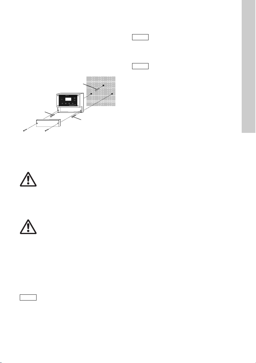
1. Drei Bohrungen (∅8 mm) gemäß Bohrbild aus-
Achtung
B
B
A
Achtung
Hinweis
führen, und die mitgelieferten Dübel einsetzen.
2. Schraube (A) in den oberen mittleren Dübel eindrehen, so dass sie ca. 1 cm übersteht.
Siehe Abb. 7.
3. Befestigungsschrauben der Blende lösen und
Blende entfernen.
4. Gerät auf Schraube (A) aufsetzen.
5. Gerät mit den beiden Schrauben (B) befestigen.
6. Blende wieder anschrauben.
Abb. 7 Montagezeichnung
10. Inbetriebnahme /
elektrische Anschlüsse
Warnung
Vor Montage Stromversorgung abschalten!
Die Schutzart IP65 ist nur gewährleistet
bei geschlossener Klemmenabdeckung
und mit entsprechenden Kabelverschraubungen oder Blindkappen.
Warnung
Vor Anschließen des Stromkabels und der
Relaiskontakte Stromversorgung abschalten! Aus Sicherheitsgründen muss der
Schutzleiter sachgemäß angeschlossen
sein!
Örtliche Sicherheitsbestimmungen beachten!
Kabelanschlüsse und Stecker vor Korrosion und Feuchtigkeit schützen.
Die Schutzart IP65 ist nur gewährleistet
bei korrekt abgedichteter Klemmenabdeckung! Dichtung auf der Klemmenabdeckung nicht beschädigen!
Dichtung der Klemmenabdeckung muss
genau positioniert werden!
Dichtung nicht beschädigen!
Ungenutzte Klemmen müssen offen bleiben.
1. Klemmenabdeckung vorn am Gerät entfernen.
2. Die entsprechenden Kabeldurchführungen verwenden und Schrauben vorsichtig anziehen.
3. Kabel für die Klemmen gemäß der Klemmenzuordnung des
Conex® DIA-1 anschließen.
4. Klemmenabdeckung wieder schließen, wobei die
Dichtung genau positioniert sein muss.
TM03 6692 4506
Deutsch (DE)
Vor Anschließen der Netzanschlussleitung prüfen, ob die Versorgungsspannung
auf dem Typenschild mit den örtlichen
Gegebenheiten übereinstimmt!
Eine falsche Spannung könnte das Gerät
zerstören!
Zur Gewährleistung der elektromagnetischen Verträglichkeit (EMV) müssen die
Eingangs- und Stromausgangsleitungen
abgeschirmt sein.
Abschirmung einseitig mit der Schirmmasse verbinden.
Schaltbild beachten! Eingangs-, Stromausgangs- und Netzanschlussleitungen in
getrennten Kabelkanälen verlegen.
63
Page 64

10.1 Klemmen
15
17 19 21 23 25
27
29 31 33 35
3634323028262422201816
15 17 19 21 23 25 27 29 31 33 35
3634323028
262422201816
37 38 39 40 41 42
37 =
38 = M
15 17
19
21 23 25 27 29 31 33 35
3634323028262422201816
PAA
H
2
O
2
15 (wh)
16 (br)
17 - 22
23 - 30
32,34,36
810
7
9
12
N.C.
N.O
.
11 13
12 14
21/22 = Pt 100
19 = + H
2
O, 20 = – H
2
O
17/18 =
1
2
3
4
Cl
2
,ClO
2
,O
3
,
H
2
O
2
,PAA
T /
+
–
mA
pH, mV, F
–
mA
mA
mA
33/35
mA
mA
39 = B/R
40 = G/C
mA
+
–
+
–
+
–
+
–
41/42 =
+/–
mV
–
pH
F
1
4
1
4
P1
P2
P2
P1
1 3 5
2 4 6
1 3 5
2 4 6
+ -
+ -
115/120 V
230/240 V
24 V/DC
NLPE
NLPE
Zellen / Elektroden
Externer
Eingang
Ausgänge
Sensoren
Zellen
Alarm
Relais
Sensoren
(Wasser)
Reglerstopp
Ausgänge
Externer
Eingang
24 V/DC
115/120 V
230/240 V
15 (weiß)
16 (braun)
Deutsch (DE)
10.1.1 Wandaufbaugehäuse Conex® DIA-1
Abb. 8
Klemmen des Wandaufbaugehäuses
TM03 6693 4506
64
Page 65

10.1.2 Schaltschrankeinschubgehäuse Conex® DIA-1
2/1
2/2
2/3
2/4
2
/1, 2/2
=
5/1 - 5/5
2/3 (+), 2/4 (–)
=
H
2
O
+
–
M B/R G/C
Pt 100
3/1 - 3/4
pH, mV, F
–
Cl
2
, ClO
2
,
O
3
,PAA,
H
2
O
2
pH, mV, F
–
3/1
3/2
3/3
3/4
4/1
4/2
4/3
4/4
7/1
7/2
7/3
N.C.
N.O.
1/1 (br), 1/2 (wh)
PAA
H
2
O
2
6/1
6/2
6/3
6/4
1
2
A 1/1 (br)
B 1/2 (wh)
PAA
H
2
O
2
A 2
/3 (+)
B 2 /4 (-)
H
2
O
1/11 1/13 4/1
1/12 1/14
4/3
4/2 4/4
3/1 3/3
3/2 3/4
B
A
1/11 -1/14
Pt 100
4/1 - 4/4
Conex DIA-1
5/1
5/2
5/3
5/4
5/5
5/1
5/2
5/3
5/4
5/5
1
2
3
4
T
mA
Cl
2
, ClO
2
,
O
3
,H
2
O
2
,
PAA
pH, mV, F
–
mA
+
–
5/1 - 5/5
4
1
1/1
1/2
1/3
1/4
1/5
1/6
1/7
1/8
1/9
1/10
1/11
1/12
1/13
1/14
8/1
8/2
8/3
PE
N
L
8/1
8/2
8/3
-
+
115/120 V
230/240 V
24 V/DC
Reglerstopp
(Wasser)
Relais
Alarm
Anschluss an
Conex
®
DIA-1
Zellen
(Wasser)
Zellen:
Ausgänge
Externer
Eingang
Sensorinterface
Zellen / Elektroden
Zellen
Elektroden
Jumper
DIP
Aus
Ein
24 V/DC
1/2 (weiß)
Abb. 9
Klemmen des Schaltschrankeinschubgehäuses
Deutsch (DE)
TM03 6979 4506
65
Page 66

Legende der Klemmen
Hinweis
Achtung
+
-
DC
R
C
AC
Deutsch (DE)
Pos. Beschreibung
Relais Relais 1 + 2
Alarmrelais
–
Alarm
N.O.: Schließer
–
N.C.: Öffner
Pt100 Temperatursensor
H
O Messwassermangelsensor
2
Stopp Reglerstopp
Ausgänge Stromausgänge [mA]
(Chlor), ClO2 (Chlordioxid),
Cl
2
1
O
(Ozon), H2O2 (Wasserstoff-
3
peroxid) oder PAA (Peressigsäure)
2 pH, mV (Redox)
3 T: Temperatur
4 Stetigregler
Eingänge Externe Eingänge [mA]
Elektroden
Messzellen, Elektroden und
Einstabmessketten
M Messelektrode
B/R Bezugselektrode
G/C Gegenelektrode
Masse
mV Redox-Elektrode
Schaltschrankeinschubgehäuse Conex
• Conex
• Sensorinterface: zur Installation nahe der Senso-
®
DIA-1: zur Installation im Schaltschrank.
ren.
10.2 Netzanschluss
1. Schaltschrankeinschubgehäuse: Die Steckerleiste an der Geräterückseite in die entsprechende Klemmenleiste stecken. Richtige Ausrichtung gewährleisten.
2. Den Schutzleiter (PE) an Klemme 5 (Wandaufbaugehäuse) oder Klemme 8/1
(Schaltschrank-einschubgehäuse) anschließen.
3. Den Neutralleiter (N) (oder den - Leiter mit
24 V-Ausführung) an Klemme 3 (Wandaufbaugehäuse) oder Klemme 8/2 (Schaltschrankeinschubgehäuse) anschließen.
4. Phase (L1) (oder den + Leiter mit 24 V-Ausführung) an Klemme 1 (Wandaufbaugehäuse) oder
Klemme 8/3 (Schaltschrankeinschubgehäuse)
anschließen.
Ein- und Ausschalten des Geräts erfolgt durch Einund Ausschalten der Stromversorgung. Ein gesonderter Ein-/Aus-Schalter ist am Gerät nicht vorhanden.
®
DIA-1
10.3 Relaisausgänge
Der Anschluss der Relaisausgänge hängt
von der Anwendung und den
verwendeten Stellgliedern ab. Nachfolgend beschriebene Anschlüsse sind daher
nur als Richtlinie zu verstehen.
Bei induktiven Lasten (auch Relais und Schütze) ist
eine Entstörung nötig. Ist dies nicht möglich, sind die
Relaiskontakte mit einer Schutzschaltung wie nachfolgend beschrieben zu schützen.
• Bei Wechselspannung:
Strom bis Kondensator C Widerstand R
60 mA 10 nF, 275 V 390 Ω, 2 W
70 mA 47 nF, 275 V 22 Ω, 2 W
150 mA 100 nF, 275 V 47 Ω, 2 W
1,0 A 220 nF, 275 V 47 Ω, 2 W
• Bei Gleichspannung: Freilaufdiode zu Relais
oder Schütz parallel schalten.
Relaisausgänge bauseitig mit einer entsprechenden Vorsicherung versehen!
Abb. 10 Schutzschaltung DC/AC
TM03 7209 2813
66
Page 67

10.4 Stromausgang
Achtung
Hinweis
Beim Stromausgang Polarität beachten!
Ω
Maximale Bürde: 500
Der Stromausgang lässt sich auf einen der beiden
Normbereiche "0-20 mA" oder "4-20 mA" oder frei
einstellen.
• Die Abschirmung einseitig mit Masse (PE)
verbinden.
Ausgang 1: Chlor, Chlordioxid, Ozon,
Wasserstoffperoxid oder Peressigsäure
Dieser Stromausgang gibt den angezeigten Messwert als analoges Stromsignal aus.
Verwendung des Stromsignals für Messwerte:
• als Eingangssignal für ein weiteres Anzeigegerät
• als Eingangssignal für einen externen Regler.
1. Den +Leiter mit Klemme 23 (Wandaufbaugehäuse) oder Klemme 1/3 (Schaltschrankeinschubgehäuse) verbinden.
2. Den -Leiter mit Klemme 24 (Wandaufbaugehäuse) oder Klemme 1/4 (Schaltschrankeinschubgehäuse) verbinden.
Ausgang 2: pH, Redox
Dieser Stromausgang gibt den angezeigten Messwert als analoges Stromsignal aus.
Verwendung des Stromsignals für Messwerte:
• als Eingangssignal für ein weiteres Anzeigegerät
• als Eingangssignal für einen externen Regler.
1. Den +Leiter mit Klemme 25 (Wandaufbaugehäuse) oder Klemme 1/5 (Schaltschrankeinschubgehäuse) verbinden.
2. Den -Leiter mit Klemme 26 (Wandaufbaugehäuse) oder Klemme 1/4 (Schaltschrankeinschubgehäuse) verbinden.
Ausgang 3: Temperatur
Dieser Stromausgang gibt die durch den optionalen
Temperatursensor gemessene Temperatur aus.
Verwendung des Stromsignals für Messwerte:
• als Eingangssignal für ein weiteres Anzeigegerät.
1. Den +Leiter mit Klemme 27 (Wandaufbaugehäuse) oder Klemme 1/6 (Schaltschrankeinschubgehäuse) verbinden.
2. Den -Leiter mit Klemme 28 (Wandaufbaugehäuse) oder Klemme 1/7 (Schaltschrankeinschubgehäuse) verbinden.
.
Ausgang 4: Stetigregelung
Dieser Stromausgang gibt das errechnete Stellgrößensignal als analoges Stromsignal aus.
Verwendung des Stellgrößensignals:
• als Eingangssignal für ein stufenloses Stellglied.
1. Den +Leiter mit Klemme 29 (Wandaufbaugehäuse) oder Klemme 1/8 (Schaltschrankeinschubgehäuse) verbinden.
2. Den -Leiter mit Klemme 30 (Wandaufbaugehäuse) oder Klemme 1/7 (Schaltschrankeinschubgehäuse) verbinden.
10.5 Anschlüsse für Reglerstopp,
Messwassersensor und
Temperatursensor
Reglerstopp anschließen
1. Den +Leiter mit Klemme 17 (Wandaufbaugehäuse) oder Klemme 2/1 (Schaltschrankeinschubgehäuse) verbinden.
2. Den -Leiter mit Klemme 18 (Wandaufbaugehäuse) oder Klemme 2/2 (Schaltschrankeinschubgehäuse) verbinden.
Wassersensor anschließen
Kabelfarben und Kennzeichnung: Siehe Anschlüsse
der Messzellentypen
AQC-D1/-D11/AQC-D2/-D12/AQC-D3/-D13.
1. Den +Leiter mit Klemme 19 (Wandaufbaugehäuse) oder Klemme 2/3 (Schaltschrankeinschubgehäuse) verbinden.
2. Den -Leiter mit Klemme 20 (Wandaufbaugehäuse) oder Klemme 2/4 (Schaltschrankeinschubgehäuse) verbinden.
Bei Verwendung der Messzelle
AQC-D2/-D12 muss der Wassersensor
immer angeschlossen und aktiviert sein!
Temperatursensor Pt100 anschließen
1. Den +Leiter mit Klemme 21 (Wandaufbaugehäuse) oder Klemme 1/11 (Schaltschrankeinschubgehäuse) verbinden.
2. Den -Leiter mit Klemme 22 (Wandaufbaugehäuse) oder Klemme 1/12 (Schaltschrankeinschubgehäuse) verbinden.
Deutsch (DE)
67
Page 68
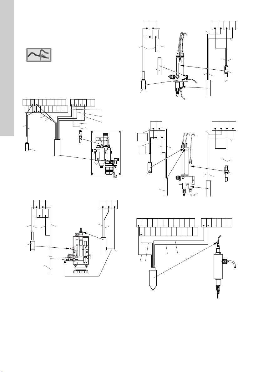
10.6 Anschluss der Messzellen
1
2
2
1:
Standard
7
5
1
37
38 39
40
41 42
6
12
4
1
15 171921 23 25 27 29 31 33 35
3634323028262422201816
9, 10, 11
8
2
3
4
21
19
2220
4
12
11
1
1
38 40
39
9
8
10
7
10
9
1
6
2
37 38
39
40
8
21
19
2220
4
12
11
1
1
7
10
9
1
6
2
37 38
39
40
8
21
19
2220
2
12
11
COM
11
1
NC
12
15 17 19 21 23 25 27 29 31 33 35
3634323028262422201816
37 38 39 40 41 42
21
14 15
Deutsch (DE)
Jumper-Einstellung
• Alle Zellentypen: Position 1 (Standard).
Abb. 11 Jumper-Einstellung
10.6.1 Anschluss des Wandaufbaugehäuses
Abb. 12
®
DIA-1
Conex
Anschluss an Messzellen
AQC-D1/AQC-D2/AQC-D3
TM03 6696 4506
TM04 8643 4112TM04 8644 4112TM03 6966 4112
Abb. 14 Anschluss an Messzellen
AQC-D12
TM03 5872 4112TM04 8642 4112
Abb. 13 Anschluss an Messzellen
AQC-D11
68
Abb. 15 Anschluss an Messzellen
Abb. 16 Anschluss an Messzellen
AQC-D13
PAA (Peressigsäure) / HP (Peroxid)
Page 69

Abb. 17 Anschluss an Einstabmessketten für
37 38 39 40 41 42
7
13
+-
1/111/
13
4/
1
1/121/
14
4/
3
4/
2
4/
4
3/13/
3
3/23/
4
B
A
1
4
Conex
2/
3
2/
4
+
-
12
MB/RG/C
7
1
6
Pt 100
2
5
8
9, 10, 11
3
4
Sensorinterface
4
11
1
Pt 100
9
8
10
1/111/
13
4/
1
1/121/
14
4/
3
4/
2
4/
4
3/13/
3
3/23/
4
B
A
1
4
Conex
2/
3
2/
4
+
-
12
G/CM
B/R
Sensorinterface
7
10
9
1
6
2
8
4
11
1
1/111/
13
4/
1
1/121/
14
4/
3
4/
2
4/
4
3/13/
3
3/23/
4
B
A
1
4
Conex
2/
3
2/
4
+
-
12
Pt 100G/CM
B/R
Sensorinterface
pH, Redox
Pos. Beschreibung
1 Braun
2Weiß
3Schwarz
4Blau
5 Abschirmung
6 Außenleiter (Abschirmung)
7 Innenleiter
8 Bezugselektrode
9 Messelektrode
10 Gegenelektrode
11 Pt100 Temperatursensor
12 Wassersensor
13 Außenleiter
14 Gelb
15 Grün
10.6.2 Anschluss des
Schaltschrank-einschubgehäuses
®
DIA-1
Conex
TM03 6967 4506
Abb. 19 Anschluss an Messzellen
AQC-D11
Deutsch (DE)
TM04 8645 4112TM04 8646 4112
Abb. 18
Anschluss an Messzellen
AQC-D1/AQC-D2/AQC-D3
Abb. 20 Anschluss an Messzellen
AQC-D12
TM03 5871 4212
69
Page 70

Deutsch (DE)
7
10
9
1
6
2
8
2111
1/111/
13
4/
1
1/121/
14
4/
3
4/
2
4/
4
3/13/
3
3/23/
4
B
A
Conex
2/
3
2/
4
+
-
12
Pt 100G/CM
B/R
COM
11
NC
12
Sensorinterface
MB/R
G/C
1/11 1/ 13 4/1
1/12 1/14
4/3
4/2 4/ 4
3/1 3/3
3/2 3/4
B
A
1/1
1/2
+
-
21
1415
+-
7
13
Abb. 21 Anschluss an Messzellen
AQC-D13
Pos. Beschreibung
1Braun
2Weiß
3Schwarz
4Blau
5 Abschirmung
6 Außenleiter (Abschirmung)
7 Innenleiter
8 Bezugselektrode
9 Messelektrode
10 Gegenelektrode
11 Pt100 Temperatursensor
12 Wassersensor
13 Außenleiter
14 Gelb
TM04 8647 4112TM03 6968 4112
15 Grün
Besonderheiten beim Anschluss an das
Schaltschrankeinschubgehäuse Conex
1. Zuerst die Messzellen, die Einstabmessketten
und die Sensoren an das Sensorinterface
anschließen.
2. Danach das Sensorinterface an den
Conex®DIA-1 anschließen.
®
DIA-1
70
Abb. 22 Anschluss an Messzellen
PAA (Peressigsäure) / HP (Peroxid)
Abb. 23 Anschluss an Einstabmessketten für
pH, Redox
TM03 6969 4506
Page 71

Anschluss des Sensorinterface an den
Hinweis
OFF
On
DIP
2
3
4
1
ClO2,O
3
Cl
2
®
Conex
DIA-1 (siehe Geräterückseite)
• Messzellen
AQC-D1/-D11/AQC-D2/-D12/AQC-D3/-D13,
PAA (Peressigsäure) / HP (Peroxid)
Die Klemmen 4/1 bis 4/14 am Sensorinterface an
die passenden Klemmen am
anschließen.
•
Messzellen HP (Peroxid) /
PAA (Peressigsäure)
Zusätzlich Klemme A an Klemme 1/1 und
Klemme B an Klemme 1/2 am
anschließen.
• Einstabmessketten
• (pH, Redox)
Die Klemmen 3/1 bis 3/4 am Sensorinterface an
die passenden Klemmen am
anschließen.
Messwassermangelsensor
•
Klemme A an Klemme 2/3 und Klemme B an
Klemme 2/4 am
Bei Verwendung der Messzelle
AQC-D2/-D12 muss der Wassersensor
immer angeschlossen und aktiviert sein!
DIP-Schalter
• Ggf. DIP-Schalter für den gewünschten Messwert auf "Ein" schalten (Schalter nach rechts
legen, der obere Schalter 1 ist nicht belegt).
Conex® DIA-1 anschließen.
Conex® DIA-1
Conex® DIA-1
Conex® DIA-1
Deutsch (DE)
Abb. 24 DIP-Schalter
TM03 6699 4506
71
Page 72

11. Bedienung
1
86
54
3
7
781
6
5
43
2
2
Deutsch (DE)
11.1 Bedien- und Anzeigeelemente
Abb. 25 Wandaufbaugehäuse und Schaltschrankeinschubgehäuse
Pos. Beschreibung
Bedienelemente
Rote Alarm-LED
1
• Blinkt bei Störungen oder falschen
Eingaben.
2 Display
Bedientasten
[OK] Taste
• Wechsel in das gewählte Auswahlmenü.
3
• Ausgewählte Zeile oder ausgewählten
Wert bestätigen.
[Down] Taste
• Zeilenweises Abwärtsbewegen
4
(die gewählte Zeile ist invers dargestellt).
• Werte verkleinern.
[Up] Taste
• Zeilenweises Aufwärtsbewegen
5
(die gewählte Zeile ist invers dargestellt).
• Werte vergrößern.
[Esc] Taste
• Rückkehr zum vorigen Menü.
6
– Die zuletzt eingegebenen Daten wer-
den nicht verändert.
Funktionstasten mit gelber LED
[Cal] Taste
• Umschalten zwischen Kalibrier- und
Messmodus.
7
– Im Kalibriermodus leuchtet die
entsprechende LED.
[Man] Taste
• Wechselt zwischen Automatik- und Hand-
8
betrieb.
– Im Handbetrieb leuchtet die
entsprechende LED.
TM03 6700 4506
72
Page 73
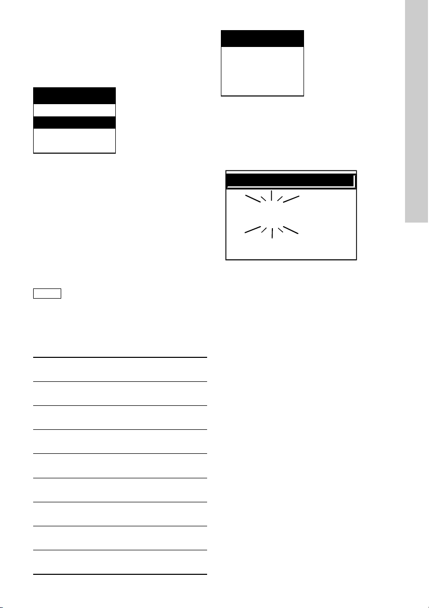
11.2 Anzeigeelemente bei erster
Hinweis
Chlor
0,43 mg / l
5,20 pH
22 °C
c
cc
Inbetriebnahme
Nach Anschluss der Stromversorgung bei der ersten
Inbetriebnahme des Gerätes und nach Erscheinen
der Startanzeige zeigt das Display das Menü
"Sprache/language".
Language/Langue...
Deutsch
English
Français
Nederlands
• Das Wort "Sprache" in der Kopfzeile wird im
Intervall von ca. einer Sekunde in allen realisierten Sprachvarianten gezeigt.
Conex® DIA-1 durch Auswahl der gewünschten
Den
Bediensprache starten:
1. Mit den Tasten [Up] und [Down] gewünschte
Sprache auswählen.
– Die ausgewählte Sprache wird invers (weiße
Buchstaben auf schwarzem Hintergrund)
angezeigt.
2. Zum Bestätigen [OK] drücken.
Die ausgewählte Sprache wird gespeichert
und bleibt beim Neustart des Geräts als
Bediensprache erhalten. Ggf. lässt sich
die Bediensprache im Untermenü "Sprache" im Menü
"Grundeinstellung" ändern.
Siehe Kapitel 11.5 Grundeinstellung.
Die Übersetzungen der Wörter "
Sprache" in den bisher verfügbaren Sprachen
und "
lauten:
Deutsch
Hauptmenü Grundeinstellung Sprache
English
main menu setup language
Français
Menu principal Paramétrage Langue
Nederlands
hoofdmenu basisinstelling taal
Español
Menu principal Ajuste básico Idioma
Italiano
Menu principale programm. fond. lingua
Português
Menu principal Posição inicial Língua
Pусский
главное меню станд. настройка язык
Polski
manu główne ustawienia język
Grundeinstellung"
Chlor
mg/l
0,43
• Nach Auswahl und Bestätigung der Bediensprache durch Drücken von [OK] bei der ersten Inbetriebnahme zeigt das Display "Chlor" als den zu
messenden Wert an.
– Bei nachfolgenden Inbetriebnahmen erscheint
in dieser Anzeige immer der zuletzt ausgewählte Messwert.
• Bei Über- oder Unterschreitung des ausgewählten Messbereiches zeigt das Display die Messbereichsobergrenze oder -untergrenze und blinkt.
Siehe Kapitel 8.4 Messbereiche und
11.5.4 Einstellen der Messbereiche für Chlor, Chlor-
dioxid, Ozon, Peroxid, Peressigsäure, pH, Redox.
Deutsch (DE)
TM03 6704 4506
73
Page 74

11.3 Software-Überblick
Hinweis
Deutsch (DE)
Vorausgesetzt, es wurden Zugangs-Codes
gesetzt, sind einige Menüs (und Untermenüs) sowie die Funktionen Cal und Man
vor unautorisierten Zugriffen geschützt.
Die geschützten Menüs sind mit "C" (Kalibrierberechtigung) oder "F"
(Vollberechtigung) versehen.
Hauptmenüs
• Regler, siehe Kapitel Regler.
• Alarm, siehe Kapitel Alarm.
• Service, siehe Kapitel Service.
• Grundeinstellung, siehe
Kapitel Grundeinstellung.
Funktionstasten
• Cal, siehe Kapitel Kalibrierfunktion.
• Man, siehe Kapitel Handbetrieb.
Regler
"F" (Vollberechtigung)
Einstellen der Parameter
• Relais 1/2
– interner/externer Sollwert
– Reglerparameter.
• Stetigregler
– interner/externer Sollwert
– Reglerparameter.
Alarm
"F" (Vollberechtigung)
• Alarmeinstellungen
– Alarmwerte (Schaltpunkte)
– Schaltrichtung
– Hysterese
– Alarmverzögerung.
• Dosierzeit-Überwachung
– maximale Dosierzeit (bei konstanter Dosierleis-
tung von 100 %).
Service
• Kalibrier-Logbuch
– die letzten 10 Kalibrierungen.
• Reglereinstellungen abfragen
• Funktion der Stromausgänge überprüfen
• Funktion der Relais überprüfen
• Funktion des Displays überprüfen.
Grundeinstellung
"F" (Vollberechtigung)
• Sprache auswählen
• Parameter: Messwerte auswählen
• Messzelle auswählen
• Messbereich auswählen
• Konfiguration der Regler
• Wassersensor ein-/ausschalten
• Zeiteinstellung
• Codefunktion
• Display-Kontrast
• Werkseinstellungen abfragen
• Stromausgang: Stromausgänge den Messbereichen zuordnen
• Programmversion abfragen.
Kalibrierfunktion
"C" (Kalibrierberechtigung)
• Kalibrierung ausgewählter Parameter
– Chlor, Chlordioxid, Ozon, Peroxid, Peressig-
säure, pH.
Handbetrieb
"C" (Kalibrierberechtigung)
• Konfigurierte Regler manuell fahren.
74
Page 75

11.4 Hauptmenü
Hinweis
1. Durch Drücken von [OK] oder ggf. durch mehrmaliges Drücken von [Esc] zum "Hauptmenue"
wechseln.
Optionen im "Hauptmenue"
Hauptmenue
Regler
Alarm
Service
Grundeinstellung
• "Regler"
In diesem Untermenü lässt sich ein Regler parametrieren. Diese Option erscheint hier nur dann,
wenn im Menü "Grundeinstellung" ein Reglertyp
ausgewählt wurde.
"Alarm"
•
In diesem Untermenü wird der Messwert mit dem
zugelassenen Wert verglichen und ggf. Alarm
ausgelöst.
"Service"
•
Diagnose-Untermenü. Der Messwert und die
letzten 10 Änderungen in den Kalibrierdaten können eingesehen werden. In diesem Modus können keine Werte geändert werden. Ist Messzelle
AQC-D2/-D12 ausgewählt, können hier die Daten
des Wassersensors eingesehen werden.
•
"Grundeinstellung"
In diesem Untermenü können die Einstellungen
für Sprache, Parameter, Messbereiche, Regler
usw. vorgenommen werden.
Auswahl der Funktionen "Kalibrierung" und
"Handbetrieb"
Siehe die Tasten [Cal] und [Man] rechts neben dem
Display.
•
Kalibrierung: [Cal] drücken, um zum Kalibrier-
menü umzuschalten (die gelbe LED leuchtet).
•
Handbetrieb: [Man] drücken, um in den Handbe-
trieb umzuschalten (die gelbe LED leuchtet).
Das Umschalten in den Handbetrieb ist nur
möglich, wenn im Menü "Grundeinstellung" ein Reglertyp ausgewählt wurde. Auf
die Funktionen "Cal" und "Man" kann nur
mit Kalibrierberechtigung oder Vollberechtigung zugegriffen werden.
Deutsch (DE)
75
Page 76

11.5 Grundeinstellung
Grundeinstellung
Parameter
Chlor
pH
pH-intern
(Elektrode)
Ein
pH-Kompensation Chlor
Ein/Aus
Temp.-Messung Ein/Aus
Temp.-Komp. Chlor
Ein/Aus
Temp.-Komp.
pH Ein/Aus
pH-extern
pH-Kompensation Chlor
Ein/Aus
Temp.-Messung Ein/Aus
Temp.-Komp. Chlor
Ein/Aus
pH
Aus
Temp.-Messung Ein/Aus
Temp.-Komp. Chlor
Ein/Aus
Chlordioxid,
Ozon
Te mp .- Me ssung Ein/Aus
Te mp . -K om
p.
Ein/Aus
Te mp .- Ko m
p.
Ein/Aus
pH
Redox
Temp.-Messung
Ein/Aus
Te mp .- Me ssung Ein/Aus
Ein
Ein
Ein
Ein
Ein
Ein
Ein
Ein
Ein
Deutsch (DE)
Alle Standardeinstellungen des Gerätes können im
Menü "Grundeinstellung" definiert werden.
Während der ersten Inbetriebnahme werden grundlegende Funktionen konfiguriert, die später selten
oder gar nicht mehr geändert werden.
Auf das Menü "Grundeinstellung" kann nur mit Vollberechtigung zugegriffen werden.
Siehe Kapitel 11.5.7 Codefunktion.
Code-Nummer eingeben.
11.5.1 Auswahl der Messwerte Chlor, Chlordioxid, Ozon, Peroxid, Peressigsäure, pH, Redox
Abb. 26
Auswahl der Messwerte im Menü "Parameter"
TM03 6707 4506
76
Page 77

1. Die Zeile "Parameter" mit den Tasten [UP] und
Chlor
0,43 mg/l
5,20 pH
22 °C
c
c
Hinweis
Chlor
0,43 mg/l
[Down] auswählen und [OK] drücken, um zum
entsprechenden Menü zu wechseln.
2. Mit den Tasten [Up] und [Down] die Zeile/n wählen, die die zu messenden Werte (Parameter)
angibt/angeben.
11.5.2 pH- und Temperaturkompensation
pH-Kompensation mit Chlormessung
Die Dissoziation von hypochloriger Säure (HOCl)
zum Hypochlorit-Anion (OCl
heitsverlust (Verringerung der Empfindlichkeit) beim
Sensor für Chlormessung.
Mit einer mathematischen Kompensationsfunktion
kann dieser Steilheitsverlust rechnerisch ausgegli-
-
) führt zu einem Steil-
chen werden.
Temperaturkompensation
Über eine Kompensationsfunktion können Temperatureinflüsse auf die Sensoren rechnerisch ausgeglichen werden.
Kontrollfeld für pH-Wert, pH-Kompensation,
Temperatur und Temperaturkompensation in der
Messwertanzeige.
11.5.3 Auswahl der Messzelle
Das Untermenü "Messzelle" erscheint nur,
wenn bei der Parametrierung die Messwerte Chlor, Chlordioxid, Ozon gewählt
wurden.
Benennungen der Messzellen, die in der Software
enthalten sind
•AQC-D1/-D11
• AQC-D2/-D12
• AQC-D3/-D13
Je nach gewähltem Messwert kann die entspre-
chende Messzelle ausgewählt werden:
• AQC-D1/-D11/AQC-D2/-D12/AQC-D3/-D13 bei
Chlor, Chlordioxid oder Ozon
Die Messzelle PAA/HP wird automatisch ausgewählt,
wenn "Peressigsäure/Peroxid" gewählt ist.
Überwachung des Reinigungsmotors
(Messzellen AQC-D1/-D11)
Nach Auswahl von Messzellentyp AQC-D1/-D11
[OK] drücken, um ins Untermenü "Reinigungsmotor"
zu wechseln.
1. Überwachung des Reinigungsmotors ein-/ausschalten.
Messzellentyp AQC-D2/-D12/-D3/-D13 gewählt
Deutsch (DE)
Abb. 27
• [Esc] ein- oder zweimal drücken, um zum Display
mit dem Messwert zu wechseln.
Siehe Kapitel 11.2 Anzeigeelemente bei erster Inbe-
triebnahme und 11.6.5 Reglerkontrollfelder im Display.
Zusätzlich zum aktuellen Messwert wird auch der
aktuelle pH-Wert und die Temperatur des Messwas-
Chlormessung mit pH- und Temperaturkompensation
sers angezeigt.
Bei aktivierter pH-Kompensation oder Temperatur-
kompensation wird am Ende der Zeile der Buchstabe
"c" für "compensation" angezeigt.
Bei deaktivierter Temperaturmessung sollte die Wassertemperatur nach der Kalibrierung von Hand eingegeben werden. Siehe Kapitel 11.9.1 Kalibrieren
des pH-Wertes.
TM03 6703 4506
Abb. 28
Chlormessung mit
AQC-D2/-D12/-D3/-D13
Ein schwarzer Balken auf dem Display zeigt die
aktuellen Daten des Wassersensors an.
Siehe Montage- und Betriebsanleitung der potentiostatischen Messzelle AQC-D2/-D12/-D3/-D13.
TM03 6708 4506
77
Page 78

11.5.4 Einstellen der Messbereiche für Chlor,
Hinweis
Achtung
01: 18: 40 pm
Uhrzeit
Zeiteinstellung
Deutsch (DE)
Chlordioxid, Ozon, Peroxid,
Peressigsäure, pH, Redox
Im Menü "Messbereiche" werden allen im Menü
"Parameter" ausgewählten Messwerten die entsprechenden Messbereiche zugeordnet.
• Im Menü "Messbereiche" stehen folgende Optionen zur Auswahl:
– Zwischen zwei (mit Redox) und sechs (Chlor)
Standardmessbereiche. Siehe Kapitel
8.4 Messbereiche.
– "Andere": Mit den Tasten [Up] und [Down] kann
der Anwender die Ober- und Untergrenze des
Messbereichs auf jeden Wert innerhalb des
größten Standardmessbereichs einstellen.
• Die Messbereiche für die Temperatur lassen sich
in °C (Celsius) oder in °F (Fahrenheit) einstellen.
Das Untermenü "Temperatur" wird nur
angezeigt, wenn die Temperaturmessung
im Menü "Parameter" eingestellt oder
wenn Parameter pH gewählt wurde.
11.5.5 Wassersensor
Im Menü "Wassermangelsensor" lässt sich der
Wassersensor ein-/ausschalten.
Bei Wassermangel wird Folgendes passieren:
• Das Störmelderelais wird aktiviert und die Alarmmeldung "Fehler Wassersensor" wird ausgelöst.
• Bei Geräten mit Regelfunktionen werden die
Stellglieder ausgeschaltet oder geschlossen.
Bei der Messzelle AQC-D2/-D12 muss der
Wassersensor eingeschaltet sein!
11.5.6 Einstellen der aktuellen Zeit (Datum/Uhrzeit/Sommerzeit)
1. Vom Menü "Grundeinstellung" in das Menü
"Datum/Uhrzeit" wechseln.
Abb. 29 Zeiteinstellung
2. Das Gerät im Menü "Zeiteinstellung" auf die aktu-
elle Zeit im Format hh.mm.ss einstellen.
– [OK] drücken, um in das nächste Nummernfeld
zu wechseln. Das aktuell aktivierte Nummernfeld blinkt.
– Mit den Tasten [Up] und [Down] die Änderun-
gen vornehmen.
– Bei längerem Tastendruck wird die Einstellge-
schwindigkeit dynamisch erhöht.
3. Im Menü "Datum" das aktuelle Datum bei Eng-
lisch als Bediensprache im Format mm.tt.jjjj oder
bei allen anderen Sprachen im Format tt.mm.jjjj
ähnlich wie beim Einstellen der Zeit einstellen.
Der entsprechende Wochentag (Mo...So) wird
automatisch angezeigt.
4. Ggf. Beginn und Ende der Sommerzeit, die Art
der Zeitverschiebung sowie Stundenzahl der
Zeitverschiebung einstellen.
11.5.7 Codefunktion
Über die Codefunktion kann die Gerätebedienung
vor unbefugtem Zugriff geschützt werden.
Vierstellige Code-Nummer eingeben und ändern
1. Die Zeile "Code Funktion" mit den Tasten [UP]
und [Down] auswählen und [OK] drücken, um
zum entsprechenden Menü zu wechseln.
Zur Auswahl stehen zwei Zugriffsberechtigungen:
Kalibrierberechtigung: Der Besitzer einer Kalibrier-
berechtigung hat Zugang zum Kalibriermenü und
zum Handbetrieb.
Der Besitzer einer Kalibrierberechtigung darf Folgendes tun:
• Kalibrierdaten ändern
• Regelrelais manuell bedienen.
Vollberechtigung: Der Besitzer einer Vollberechti-
gung hat Zugang zu allen Einstellungen einschließlich den Kalibrierdaten.
TM03 6709 4506
78
Page 79

Der Besitzer einer Vollberechtigung darf Folgendes
Hinweis
Hinweis
Hinweis
Achtung
Achtung
tun:
• Kalibrierdaten ändern
• Grundeinstellung ändern
• Regler parametrieren
• Alarmeinstellungen ändern
• Gerät manuell fahren.
CAL-Berechtigung
Code 0000
alter Code
2. Die gewünschte Zugriffsberechtigung auswählen
und [OK] drücken, um in das entsprechende
Menü zu wechseln.
3. Existiert ein alter Code, die alte Code-Nummer
zuerst bestätigen (bei erster Anwendung
Code 0000 bestätigen).
4. "ändern" wählen.
5. Im Untermenü den alten Code (siehe Kommentarzeile unten im Display) mit den Tasten [Up]
und [Down] eingeben, zur Bestätigung [OK] drücken und zur Abfrage "neuer Code" (siehe Kommentarzeile unten im Display) wechseln.
6. Mit den Tasten [Up] und [Down] eine neue vierstellige Code-Nummer eingeben. Zum Bestätigen
[OK] drücken.
7. Zugriffsberechtigungen lassen sich durch
Löschen der entsprechenden Code-Nummer im
Untermenü "Löschen" aufheben.
• Bei Eingabe einer vierstelligen Code-Nummer
wird der Zugang für die entsprechenden Bedienfunktionen innerhalb einer begrenzten Zeit von
60 Min. ermöglicht.
• Wurde zuvor kein Code vorgegeben, erfolgt der
ungehinderte Zugriff auf das gewünschte Menü.
Die Code-Nummer 0000 wird nicht angezeigt /
der Anwender wird nicht zur Eingabe aufgefordert.
Bei Eingabe eines falschen Codes wird der
Zugriff auf die entsprechenden Menüs verweigert.
Eine Feldermeldung wird ausgelöst
(Dauer: fünf Sekunden), und das Gerät
kehrt zum "Hauptmenue" zurück.
11.5.8 Rücksetzfunktion
• Die Eingabe der Code-Nummer "1998" löscht alle
zuvor eingegebenen Code-Nummern.
• Alle früheren Zugangscodes werden gelöscht
und auf "0000" zurückgesetzt.
11.5.9 Display-Kontrast verstellen
Im Menü "Display" kann der Kontrast des Displays
eingestellt werden.
1. Vom Menü "Grundeinstellung" zum Menü
"Display" mit den Tasten [UP] und [Down] wechseln und zur Bestätigung [OK] drücken.
Bei zu hoch eingestelltem Kontrast ist das
Display unter Umständen nicht lesbar.
Taste [Down] gedrückt halten bis der Kontrast so eingestellt ist, dass das Display
wieder lesbar ist.
11.5.10 Speichern von / Zugriff auf
Anwendereinstellungen
Im Untermenü "Werkseinstellung" kann die aktuelle
Geräteeinstellung zur späteren Reaktivierung
gespeichert oder eine gespeicherte Einstellung aktiviert werden.
• Grundeinstellung
- Grundeinstellung speichern: Alle aktuellen Geräteeinstellungen des Menüs (nicht nur die Einstellungen unter "Grundeinstellung") werden gespeichert.
- Grundeinstellung aktivieren: Gerät wird auf die
zuletzt gespeicherte Grundeinstellung zurückgesetzt.
In diesem Menü alle Geräteeinstellungen
speichern, sobald die Werte in den Menüs
"Grundeinstellung, "Regler" und "Alarm"
eingestellt wurden.
Sie lassen sich dann jederzeit wieder aktivieren (sogar nach dem Zurücksetzen auf
Werkseinstellung)!
11.5.11 Zurücksetzen auf Werkseinstellung
Im Untermenü "Werkseinstellung" lässt sich der
Conex® DIA-1 auf Werkseinstellung mit Code 6742
zurücksetzen.
Diese Funktion nur im Notfall verwenden.
Alle Geräteeinstellungen gehen verloren
und müssen erneut eingegeben werden!
Das Gerät während des Zurücksetzens
nicht von der Stromversorgung trennen!
Rückstellung des Conex® DIA-1 auf
Werkseinstellung
• Zurücksetzen
- Code: 0000 wird angezeigt.
- Code 6742 mit den Tasten [Up] und [Down] einstellen und zur Bestätigung [OK] drücken.
Das Gerät ist jetzt auf die originale Werkseinstellung
zurückgesetzt.
Vor Wiederinbetriebnahme:
Alle Parameter überprüfen und das Gerät
gemäß des Verwendungszwecks einstellen!
Deutsch (DE)
79
Page 80

Allgemeine Werkseinstellungen
Deutsch (DE)
• Sprache: Der Conex
der Sprache. Die Sprachen "Deutsch/English
Français...." werden abwechselnd angezeigt.
®
DIA-1 wartet auf Eingabe
• Sommerzeit: Aus.
• Code-Nummern: 0000 Kalibrierberechtigung,
0000 Vollberechtigung.
Parametereinstellungen
• Stromausgänge: 0-20 mA.
• Mit frei einstellbaren Grenzwerten:
– Untergrenze = unteres Ende des Messbereichs
– Obergrenze = oberes Ende des Messbereichs.
• Alarmwerte: Alarm aus.
• Dosierzeit-Überwachung: Aus.
Cl
2
Messbereich [mg/l]
0,00 - 2,00 0,00 - 1,00 0-100 0-100
Messzelle AQC-D1/-D11/-D3/-D13/-D2/-D12
ClO2/O
3
H2O
2
HP
(Peroxid)
PAA
PAA
(Peressigsäure)
pH-Messung Aus - - -
Reinigungsmotorüberwachung
Aus Aus - -
Wassermangelsensor Aus Aus Aus Aus
Stromausgang 0-20 mA 0-20 mA 0-20 mA 0-20 mA
Alarm-Bestätigung Alarm-Bestätigung Alarm-Bestätigung Alarm-Bestätigung
pH Redox
Messbereich [mg/l]
2,00 - 12,00 0-1000
Sensorsteigung [mV]/[pH] -58 [mV]/[pH] -
Asymmetriepotential 0-
Kalibriertemperatur [°C] 25 25
Wassermangelsensor Aus Aus
Stromausgang 0-20 mA 0-20 mA
Alarm-Bestätigung Alarm-Bestätigung
Werkseinstellungen der Regler
• Schaltender Regler:
– Ausgang 1: Aus
– Grenzwertgeber / Ausgang 2: Aus
• Zweipunktregler:
– Schaltrichtung oder Regelrichtung Ausgang 1:
Unterschreitung
– Schaltrichtung oder Regelrichtung Ausgang 2:
Überschreitung
• Reglerverhalten bei allen Reglern: PI
• Stromausgang Stetigregler: 0-20 mA.
80
Page 81
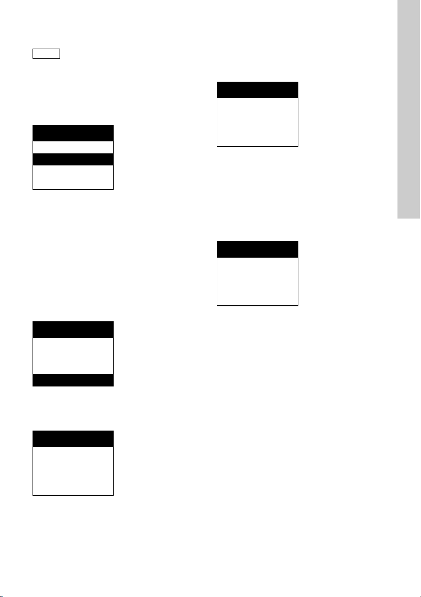
11.5.12 Stromausgänge
Hinweis
Darauf achten, dass der gewählte Ausgang mit dem gewählten Parameter übereinstimmt.
Im Menü "Stromausgang" kann der Anwender die
ausgewählten Werte den Stromausgängen zuordnen
und anschließend die Stromausgänge den eingestellten Messbereichen zuordnen.
Im Menü "Stromausgang" sind die gewählten Parameter in folgender Reihenfolge angeordnet:
Stromausgang
2. Den dazugehörigen unteren Stromgrenzwert mit
Taste [Up] eingeben. Zum Bestätigen [OK]
drücken.
– Eine weitere Abfrage für den oberen Grenzwert
des Messbereichs, der "20,00 mg/l" beträgt,
wird angezeigt.
Chlor
0,20 mg/l = 0 mA
15,00 mg/l = 20 mA
Deutsch (DE)
Chlor
pH
Temperatur
• Ausgang 1: Cl
, ClO2, O3, H2O2, PAA
2
• Ausgang 2: pH, Redox
• Ausgang 3: Temperatur
• Ausgang 4: Stetigregler.
Stromausgänge dem Messbereich zuordnen
(Beispiel: Chlormessung)
Es gibt zwei Normbereiche, "0-20 mA" und
"4-20 mA", die den Stromausgängen zugeordnet
werden können. Sie werden dem Messbereich linear
zugeordnet.
Die Ober- und Untergrenzen für die Stromausgänge
1 bis 3 können innerhalb des Intervalls 0-20 mA frei
definiert werden.
Chlor
0-20 mA
4-20 mA
Andere
1. Zur freien Einstellung die Zeile "Andere" im entsprechenden Untermenü mit den Tasten [Up] und
[Down] wählen. Zum Bestätigen [OK] drücken.
– In der gleichen Zeile wird "= 0 mA" angezeigt.
Chlor
3. Den oberen Grenzwert des Messbereichs mit der
Taste [Down] eingeben. Zum Bestätigen [OK]
drücken.
– In der gleichen Zeile wird "= 20 mA" angezeigt.
4. Den dazugehörigen oberen Stromgrenzwert mit
Taste [Down] eingeben. Zum Bestätigen [OK]
drücken und zum Menü "Stromausgang" zurückkehren.
11.5.13 Programmversion
Grundeinstellung
V0.20.1 19991028
Programmversion
Wenn Probleme die Kontaktaufnahme mit der Servicewerkstatt nötig machen, ermöglicht die "Programmversion" dem Anwender die Software-Komponenten des Gerätes schnell zu identifizieren.
• Version: zum Beispiel
• Softwarestand:
v0.20.1.
jjjjmmtt.
0,20 mg/l = 0 mA
81
Page 82

11.6 Auswahl, Konfigurierung und
Grundeinstellung
Regler
Schaltender Reg.
Grenzwert/
2Punkt
Relais
1/2
Aus
Grenzwertgeber
Unterschreitung
Überschreitung
Pulspausenregler
Abwärtsregelung
Aufwärtsregelung
P
PI
PID
Sollwert
extern/
intern
Pulsfreq.Regler
Einstellung, siehe
Pulspausenregler
Stetigregler
Dreipunktschritt
Aus
Aus
Einstellung, siehe
Pulspausenregler
Einstellung, siehe
Pulspausenregler
Deutsch (DE)
Parametrierung des Reglers
Das Einstellen des Reglers erfolgt in zwei Schritten:
• Erster Schritt: Auswahl und Konfigurierung des
Reglertyps im Menü "Grundeinstellung", Untermenü "Regler".
• Zweiter Schritt: Parametrierung des ausgewählten Reglertyps im "Hauptmenue", Untermenü
"Regler".
11.6.1 Auswahl und Konfigurierung des Reglers
Abb. 30
• Im Menü "Grundeinstellung" mit den Tasten [Up]
und [Down] die Zeile "Regler" wählen und [OK]
drücken, um in das Menü "Regler" zu wechseln.
82
Auswahl und Konfigurierung des Reglers
TM03 6711 4506
Page 83

11.6.2 Auswahl, Konfigurierung eines
schaltenden Reglers
1. Die Zeile "Schaltender Reg." mit den Tasten [UP]
und [Down] auswählen und [OK] drücken, um
zum Menü "Schaltender Reg." zu wechseln.
2. Mit Taste [Up] und [Down] die Zeile
"Grenzwert/2Punkt" wählen.
3. [OK] drücken, um automatisch zum Menü
"Relais 1" zu springen.
4. Mit den Tasten [Up] und [Down] eine der folgenden Optionen wählen:
– Aus
– Grenzwertgeber
– Pulspausenregler (Zweipunktregler)
– Pulsfrequenzregler (Zweipunktregler).
Wenn ein Grenzwertgeber/Zweipunktregler ausgewählt wurde, kann ein weiterer Grenzwertgeber/Zweipunktregler ausgewählt werden. Ein zusätzlicher Dreipunktregler steht nicht zur Auswahl.
– Nach Beendigung der Konfigurierung des ers-
ten Zweipunktreglers/Grenzwertgebers
(Relais 1) [OK] drücken, um zu "Relais 2" zu
springen.
Wenn ein Dreipunktschrittregler gewählt wurde, kann
zusätzlich weder ein Grenzwertgeber noch ein Zweipunktregler gewählt werden.
Zweipunktregler und Dreipunktschrittregler:
Hinsichtlich des Reglerverhaltens kann einer der
folgenden Regeltypen gewählt werden:
• P: Verhältnisregler (nicht beim Dreipunktregler)
• PI: Proportional-Integral-Regler
• PID: Proportional-Integral-Differenzial-Regler
(nicht bei Dreipunktregler).
Hinsichtlich des Sollwerts gilt Folgendes:
• Wurde ein interner Sollwert gewählt, sind Einstellungen innerhalb des Messbereichs möglich.
• Wurde ein externer Sollwert gewählt, besteht für
den Anwender die Wahl zwischen den Standardstromausgängen 0-20 mA und 4-20 mA.
11.6.3 Auswahl und Konfigurierung des Stetigreglers
Der Stetigregler kann immer verwendet werden.
1. Die Zeile "Stetigregler" im Menü "Grundeinstel-
lung" mit den Tasten [Up] und [Down] wählen und
[OK] drücken, um in das Menü "Stetigregler" zu
wechseln.
2. Die Regelrichtung lässt sich, ähnlich wie bei den
Zweipunktreglern, auf Aufwärtsregelung
(Unterschreitung des Sollwerts) oder Abwärtsregelung (Überschreitung des Sollwerts) stellen.
Siehe Kapitel 11.6.2 Auswahl, Konfigurierung
eines schaltenden Reglers.
3. Hinsichtlich des Reglerverhaltens kann einer der
Reglertypen P, PI, PID gewählt werden.
Siehe Kapitel 11.6.2 Auswahl, Konfigurierung
eines schaltenden Reglers.
• Hinsichtlich des Sollwerts gilt Folgendes:
– Wurde ein interner Sollwert gewählt, sind Ein-
stellungen innerhalb des Messbereichs möglich.
– Wurde ein externer Sollwert gewählt, besteht
für den Anwender die Wahl zwischen den Standardstromausgängen 0-20 mA und
4-20 mA.
Deutsch (DE)
83
Page 84

11.6.4 Einstellen der Reglerparameter
Hinweis
Einstellungen, siehe oben und Kapitel 8.3
Einstellungen, siehe oben und Kapitel 8.2
Regler
Hauptmenue
d.h.
Pulspausenregler
Relais 1 Sollwert
Sollwert
extern
Sollwert
intern
0-20 mA / 4-20 mA
Chlor 0,00-20,00 mg/l
pH 0-14,00 pH
0,0 bis 3000,0 %
Prop.-bereich XP
Nachstellzeit TN
Vorhaltezeit TV
Puls+Pausenzeit
Min. Einschaltd.
Grundlast
Max. Dosierleist.
Adaption
1 bis 3000 s
1 bis 1000 s
1 bis 100 s
0,1 bis 10,0 s
0 bis 50 %
0 bis 100 %
Beginn
Stop
Adapt.
Ergebnis
Stetigregler
Relais 2
Deutsch (DE)
1. Einen Regler im Menü "Grundeinstellung" auswählen und konfigurieren.
Siehe Kapitel 11.6 Auswahl, Konfigurierung und
Parametrierung des Reglers.
2. Im "Hauptmenue" mit den Tasten [Up] und
[Down] die Zeile "Regler" wählen und [OK]
drücken, um in das Menü "Regler" zu wechseln.
Siehe Kapitel 11.4 Hauptmenü.
Die Option "Regler" im "Hauptmenue" ist
nur verfügbar, wenn im Menü "Grundeinstellung" ein Regler gewählt wurde!
Beispiel:
Konfigurierter Grenzwertgeber oder Zwei-
punktregler und aktivierter Stetigregler.
Abb. 31 Einstellen der Reglerparameter
Die im Untermenü "Regler" (Hauptmenue) verfügbaren Optionen entsprechen der im Menü "Grundeinstellung" vorgenommenen Konfiguration.
1. Mit den Tasten [Up] und [Down] die internen Sollwerte innerhalb des gewählten Messbereichs
ändern.
Siehe Kapitel 8.4 Messbereiche.
84
2. Die angezeigten Reglerparameter mit den Tasten
[Up] und [Down] wählen, [OK] drücken, um in das
gewünschte Untermenü zu wechseln, und mit
den Tasten [Up] und [Down] die innerhalb der
zugelassenen Bereiche benötigten Sollwerte einstellen.
Siehe Kapitel 8.3.3 Reglerfunktionen.
TM03 6712 4506
Page 85

11.6.5 Reglerkontrollfelder im Display
12
Chlor
0,43 mg/l
5,20 pH
22 °C
c
c
12
Stetigregler
Relais 2
Relais 1
Externer Sollwert
1
1
• Die Kontrollfelder für die Relais 1 und 2 werden
angezeigt, wenn ein Grenzwertgeber /
Zweipunktregler konfiguriert wurde:
Nicht ausgefülltes Feld bei Relais aus:
Abb. 32
1. [Esc] ein- oder zweimal drücken, um zum Display
"Messwert" zu wechseln.
Siehe Kapitel 11.2 Anzeigeelemente bei erster Inbe-
triebnahme und 11.5.2 pH- und Temperaturkompensation.
Die im Display "Messwert" angezeigten Kontrollfelder entsprechen dem konfigurierten Regler.
• Das Kontrollfeld ">" wird nur angezeigt, wenn ein
externer Sollwert definiert wurde. Je nach
gewähltem Normbereich (0-20 mA oder 4-20 mA)
und definiertem Sollwertniveau wird es nicht ausgefüllt, teilweise ausgefüllt oder ganz ausgefüllt
(invers) gezeigt.
Chlormessung mit pH- und Temperaturkompensation
Nicht ausgefüllt (bei 0 oder 4 mA):
Ausgefülltes Feld (invers dargestellt) bei Relais
ein:
TM03 6713 4506TM03 6714 4506
• Das Kontrollfeld für den Stetigregler wird angezeigt, wenn ein Stetigregler konfiguriert wurde.
Je nach eingestellter Dosierleistung ist es leer
oder von einem schwarzen Balken ausgefüllt, der
die aktuelle Dosierleistung im Verhältnis zur
maximalen Dosierleistung der Anlage zeigt.
Beispiel:
0 %:
50 %:
100 %:
Deutsch (DE)
Teilweise ausgefüllt, beispielsweise bei Sollwert
4 mA (Normbereich 0-20 mA):
Ganz ausgefüllt, beispielsweise bei Sollwert
20 mA (Normbereich 0(4) bis 20 mA):
85
Page 86
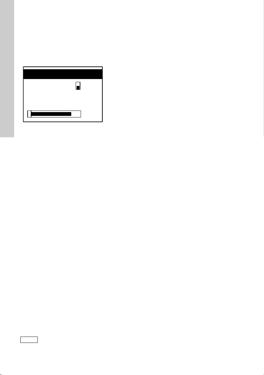
11.6.6 Adaption
Hinweis
Chlor
0,43 mg/l
Adaption
Deutsch (DE)
Um die Einstellung der Reglerparameter zu vereinfachen, kann eine Adaption gestartet werden.
Die Adaption ist nur bei PI- und PID-Reglern möglich.
1. Im Menü "Regler" (Hauptmenue) unter "Adaption" durch Drücken von "Beginn" die Adaption
starten.
Abb. 33 Chlormessung bei Adaption des Steti-
greglers
2. Automatische Rückkehr zum Display "Messwert".
Ein schwarzer Balken auf dem Display zeigt den
Verlauf der Adaption an. Die LED neben der
Taste [Man] blinkt während der gesamten Adaption. Ein Fortschrittsbalken veranschaulicht den
zeitlichen Ablauf der Adaption.
• Die konfigurierten Regler können nur nacheinander adaptiert werden.
• Der Messwert muss bei Aufwärtsregelung mehr
als 20 % unter dem Sollwert liegen.
• Der Messwert muss bei Abwärtsregelung mehr
als 20 % über dem Sollwert liegen.
Im Fehlerfall tritt direkt nach dem Start die Meldung
"Startbedingungen falsch" auf.
3. Nach Beendigung der Adaption erscheint die
Meldung "Adaption fehlgeschlagen".
4. Zum Beenden [OK] oder [Esc] drücken.
Die ermittelten Reglerwerte werden bei der Parametrierung des Reglers automatisch adaptiert.
Sie werden im Adaptionsmenü unter
"Adapt. Ergebnis" angezeigt.
5. Bei einer nicht erfolgreichen Adaption erscheint
die Meldung "Adaption fehlgeschlagen".
Zum Beenden [OK] oder [Esc] drücken.
Die Adaption wird in folgenden Fällen abgebrochen:
• wenn eine Fehlermeldung während der Adaption
auftritt.
• wenn der Regler auf Handbetrieb eingestellt wird.
• wenn die Stillstandszeit mehr als 1 h beträgt.
• wenn die gesamte Messzeit mehr als 2 h beträgt.
Bei einer nachträglichen Änderung des Sollwertes
werden die ermittelten Reglerparameter automatisch
kompensiert.
Bei gewählter Temperatur-, pH- und
Redox-Messung werden während der
Adaption die Temperatur-, pH- und
Redox-Werte und deren Kompensationen
nicht angezeigt.
86
TM03 6715 4506
Page 87

11.7 Menü "Alarm"
Alarm
Hauptmenue
Alarmwerte Alarm aus
Alarm ein
Alarmwert 1
(Schaltpunkt 1)
Alarm
Unterschreitung
Über-
schreitung
Unterschreitung
Über-
schreitung
Alarmwert 2
(Schaltpunkt 2)
Hysterese
Alarmverzögerung
Hinweis
Mit Hilfe der Alarm-Funktion kann der Messwert
überwacht und mit dem zugelassenen Bereich verglichen werden.
Überschreitet der Messwert die Grenzwerte des
Messbereichs wird Alarm ausgelöst.
• Das Alarmrelais wird nach Ablauf der eingestellten Alarmverzögerungszeit aktiviert.
• Wird die Ursache für den Alarm behoben, wird
das Relais sofort (ohne Verzögerung) deaktiviert.
Deutsch (DE)
Abb. 34 "Alarm" im "Hauptmenue"
1. Zeile "Alarm" im "Hauptmenue" mit den Tasten
[Up] und [Down] wählen.
2. [OK] drücken, um in das Menü "Alarm" zu wechseln.
Dort stehen zwei Funktionen zur Verfügung:
Alarm
Alarmwerte
Dosierzeitüberw.
•
Alarmwerte: Überschreitet der Messwert den
zulässigen Bereich, wird das Alarmrelais aktiviert
und eine Alarmmeldung ausgelöst. Die rote
Alarm-LED beginnt zu blinken.
TM03 6716 4506
Dosierzeitüberw.: Bleibt die Dosierleistung
•
innerhalb der gewählten maximalen Dosierzeit
konstant bei 100 %, wird das Alarmrelais aktiviert
und eine Alarmmeldung ausgelöst. Die rote
Alarm-LED beginnt zu blinken.
Die Dosierzeitüberwachung wird bei Dreipunktreglern nicht aktiviert!
87
Page 88

Alarmwerte einstellen
Deutsch (DE)
1. Die Zeile "Alarmwerte" mit den Tasten [Up] und
[Down] wählen. [OK] drücken, um in das Untermenü "Alarm ein/Alarm aus" zu wechseln.
– Wird "Alarm aus" gewählt, kehrt das Gerät zum
Menü "Alarm" zurück, wenn [OK] gedrückt
wurde.
2. [OK] drücken, um in das Untermenü "Alarm
ein/Alarm aus" zu wechseln.
Oberen und unteren Schaltpunkt (Grenzwerte)
einstellen
1. Die Zeile "Alarmwert 1" oder "Alarmwert 2" wählen. Zum Bestätigen [OK] drücken und zum
gewünschten Menü wechseln.
Alarmwert 1
0,00 mg/l
Schaltpunkt 1
2. Die Schaltpunkte zwischen 0 und dem vorher
festgelegten oberen Grenzwert des Messbereichs mit den Tasten [Up] und [Down] einstellen
(in der Einheit des Messwertes, die Auflösung ist
abhängig vom gewählten Messwert und Messbereich).
Siehe Kapitel 8.4 Messbereiche.
3. [OK] drücken, um in das Menü "Schaltrichtung"
zu wechseln.
Optionen: Alarmmeldung bei Über- oder Unterschreitung des gewählten Schaltpunktes.
4. Die gewünschte Zeile mit den Tasten [Up] und
[Down] auswählen.
5. [OK] drücken, um automatisch zum Menü "Alarmwerte" zurückzukehren.
6. Die Zeile "Hysterese" im Menü "Alarmwerte" auswählen und [OK] drücken, um in das entsprechende Untermenü zu wechseln.
Alarmwerte
8. [OK] drücken, um zum Menü "Alarmwerte"
zurückzukehren.
9. Die Zeile "Alarmverzögerung" im Menü "Alarmwerte" auswählen und [OK] drücken, um in das
entsprechende Untermenü zu wechseln.
Alarmwerte
0 sec
Alarmverzögerung
10. Alarmverzögerung mit den Tasten [Up] und
[Down] auf einen Wert zwischen 0 und
300 Sekunden einstellen.
11.7.1 Dosierzeit-Überwachung
Diese Funktion dient zur Überwachung des Dosierprozesses (Ausnahme: Dreipunktregler). Liegt die
Dosierleistung in dem gewählten Zeitraum konstant
bei 100 %, wird eine Alarmmeldung ausgelöst.
Dosierzeitüberw.
10 min
max. Dosierzeit
1. Die Zeile "Dosierzeitüberw." im Menü "Alarm"
auswählen und [OK] drücken, um in das entsprechende Untermenü zu wechseln.
Im Menü "Dosierzeitüberw." kann die Überwachungsfunktion ein- oder ausgeschaltet werden.
• Bei Auswahl von "aus" kehrt das Gerät zurück
zum Menü "Alarm".
• Bei Auswahl von "ein" erscheint das Untermenü
"Dosierüberw.".
2. Die maximale Dosierzeit mit den Tasten [Up] und
[Down] auf einen Wert zwischen 0 und
600 Minuten einstellen.
0,00 mg/l
Hysterese
7. Hysterese mit den Tasten [Up] und [Down] auf
einen Wert zwischen 0 und halbem Messbereich
einstellen.
Die Hysterese sorgt beim Über- oder Unterschreiten
der Grenzwerte dafür, dass die Relais weniger häufig schalten.
88
Page 89

11.8 Einstellungen im Menü "Service" überprüfen
Hinweis
Hauptmenue
Service
Chlor
CalData/
Logbuch (5)
- Nummer (Datensatz 1-10)
- Cal Datum
- Cal Zeit
- Steigung
- Cal Temp. (1)
- Cal pH (2)
Messwert
Wassersensor (4)
aktueller Zellenstrom in µA
aktueller Messwert in mg/l
Cal Wert in 1/min
aktueller Messwert 1/min
Regler (3)
Test Str o m
Te st
Relais
Test Display
Reglerparameter
Stromausgänge 1-4
Relais 1/2/3 Ein / Aus
Werte 0(4) mA / 10 mA /
20 mA Ein/Aus
Das Menü "Service" dient dem Anwender dazu, im
Servicefall alle wichtigen Einstellungen abzufragen
und Gerätefunktionen zu überprüfen.
Im Menü "Service" lassen sich Kali-brierdaten und Reglereinstellungen nicht
ändern. Daher ist das Menü ohne
Zugangscode zugänglich.
Die Zeile "Service" im Menü "Hauptmenue" auswählen und [OK] drücken, um in das entsprechende
Untermenü zu wechseln.
Deutsch (DE)
Abb. 35 Beispiel: Chlormessung
TM03 6717 4506
89
Page 90

Hinweise zu Ziffern in Abb. 35:
Deutsch (DE)
"Cal Temp." wird nur angezeigt, wenn Temperaturmessung oder Temperaturkompen-
(1)
sation im Menü "Grundeinstellung" eingeschaltet wurde.
"cal pH" wird nur angezeigt, wenn pH-Mes-
(2)
sung oder pH-Kompensation im Menü
"Grundeinstellung" eingeschaltet wurde.
"Regler" wird nur angezeigt, wenn ein Regler in Menü "Grundeinstellung" und im
(3)
"Hauptmenue" gewählt und konfiguriert
wurde.
"Wassersensor" wird nur angezeigt, wenn
(4)
eine Messzelle AQC-D2/-D12 im Menü
"Grundeinstellung" gewählt wurde.
"CalData-Logbuch" wird nur angezeigt,
(5)
wenn bereits eine Kalibrierung erfolgt ist.
Service
Chlor
Test St r o m
Test Relais
Im Menü "Service" werden folgende Punkte aufgeführt:
• "Messwert": Anzeigen der Daten der letzten
10 Kalibrierungen.
• "Regler": Reglereinstellungen überprüfen.
• "Test Strom": Funktion der Stromausgänge überprüfen.
• "Test Relais": Funktion der Relais überprüfen.
• "Test Display": Funktion des Displays überprüfen.
"Messwert": Logbuch-Aufzeichnung der
Kalibrierdaten
Die Kalibrierdaten aller aktivierten Messwerte werden durch eine Logbuch-Funktion chronologisch
erfasst (Ausnahme: Redox-Messung!).
Beispiel: Bei pH-Messung werden im Logbuch fol-
gende Daten aufgelistet:
• Kalibriernummer mit Datum/Uhrzeit
• Steigung (Empfindlichkeit der Elektrode)
• Asymmetriepotential der Elektrode
• Temperatur der verwendeten Pufferlösung
• kalibrierter Messwert.
Unter "Messwert" werden folgende Daten angezeigt:
• aktueller Messwert
• aktuelle Zellenspannung oder aktueller Zellenstrom.
Unter "Wassersensor" werden folgende Daten angezeigt:
• Drehzahl des Wassersensors während der letzten Kalibrierung
• aktuelle Drehzahl des Wassersensors.
"Regler" (Reglereinstellungen überprüfen)
1. Je nach Konfiguration Relais 1, Relais 2 oder
Stetigregler mit den Tasten [Up] und [Down] auswählen und [OK] drücken, um in das entsprechende Menü zu wechseln.
– In der ersten Zeile steht der konfigurierte Reg-
lertyp, und in den nachfolgenden Zeilen sind
die aktuellen Reglereinstellungen aufgelistet.
(Mit [OK] Wert y
auswählen).
out
"Test Strom" (Funktion der Stromausgänge
überprüfen)
1. Den zu testenden Stromausgang mit den Tasten
[UP] und [Down] auswählen und [OK] drücken,
um zum entsprechenden Menü zu wechseln.
Je nach Konfiguration der Stromausgänge können
die Stromausgänge mit folgenden Stromwerten eingeschaltet und der Stromwert an das System ausgegeben werden:
• Testströme von 0, 10, 20 mA bei gewähltem
Normbereich 0-20 mA
• Testströme von 4, 12, 20 mA bei gewähltem
Normbereich 4-20 mA oder bei frei eingestellten
Stromausgängen.
2. Die Stromwerte mit den Tasten [Up] und [Down]
wählen.
– Bei Auswahl einer Zeile wird automatisch der
Status des Stromausgangs mit dem entsprechenden Wert auf Ein gestellt.
– Bei Auswahl einer anderen Zeile wird der vor-
herige Stromwert automatisch ausgeschaltet
und der neue Stromwert auf Ein gestellt.
"Test Relais" (Funktion der Relais überprüfen)
1. Das zu testende Relais mit den Tasten [UP] und
[Down] auswählen und [OK] drücken, um es einoder auszuschalten.
– Wenn eine der Zeilen "Relais 1" oder "Relais 2"
ausgewählt wurde, wird das Relais, das vor
dem Zugriff auf das Testmenü zuletzt aktiviert
war, ausgeschaltet. Das Relais wird, unter
Berücksichtigung der aktuellen Alarmwerte
und Stromwerte, nach Verlassen des Menüs
wieder eingeschaltet.
"Test Display"
(Funktion des Displays überprüfen)
• Wird das Display vollständig dunkel:
Das Display funktioniert einwandfrei.
• Bleibt das Display stellenweise hell:
Display ist fehlerhaft.
• [OK] drücken, um das Testmenü zu verlassen.
90
Page 91

11.9 Kalibrierung
Hinweis
Steigung /
Asymmetriepot.
CAL Ergebnis
CAL Intervall
1-100 Tage
"Cal"
pH
CAL
Messwert
GRUNDFOS
DIN /
NIST
Andere
Temperatur
der Puffer-
lösung
Puffer 1/2
automatisches Lesen
von
- MesswasserTemperatur
- Messsignal und
automatische
Kalibrierung
CAL Ergebnis:
Steigung /
Asymmetriepot.
Ein
manuelle
Te mp .
1. [Cal] drücken, um in das Kalibriermenü zu
wechseln.
– Die LED neben [CAL] leuchtet.
2. Je nach eingestellter Zugangsberechtigung muss
ggf. eine vierstellige Code-Nummer mit Hilfe der
Tasten [Up] und [Down] eingegeben werden.
3. [OK] drücken, um in das Menü "Messwert" zu
wechseln.
Zur Vermeidung einer Überdosierung werden die
Regler ausgeschaltet und die Stellglieder zugefahren.
Besonderheiten beim Kalibrieren von Chlor mit
pH-Kompensation
• [OK] drücken, um in das Menü "Kalibrierung" zu
wechseln.
Zwei Optionen stehen zur Verfügung: (Messwert)
"Chlor" (erste Zeile) und "pH" (zweite Zeile).
Die pH-Kalibrierung ist vorrangig auszuführen, da das Gerät beim Kalibrieren des
Chlorwertes auf den bereits kali-brierten
pH-Messwert als Referenzwert zurückgreift.
Deshalb zuerst den pH-Wert kalibrieren!
Erst danach den Chlorwert kalibrieren!
11.9.1 Kalibrieren des pH-Wertes
Deutsch (DE)
Abb. 36
Kalibrieren des pH-Wertes
TM03 6718 4506
91
Page 92

Die pH-Kalibrierung wird als eine Zweipunktkalibrie-
Deutsch (DE)
rung ausgeführt.
pH
CAL Messwert
manuelle Temp.
CAL Ergebnis
CAL Intervall
1. [Cal] drücken, um zur Kalibrierfunktion zu schalten. Die Zeile "pH" auswählen und [OK] drücken,
um in das Kalibriermenü "pH" zu wechseln.
2. "CAL Messwert" auswählen und [OK] drücken,
um in das entsprechende Menü zu wechseln.
Auswählen von Puffertypen und Pufferwerten,
Einlesen von Pufferwerten und Kalibrieren
Zur Auswahl stehen drei optionale Puffertypen:
• GRUNDFOS: Pufferwerte pH 4,01, 7,00, 9,18.
• DIN/NIST: Pufferwerte pH 4,01, 6,86, 9,18.
• "Andere": Unterer und oberer Pufferwert frei einstellbar (Differenz mindestens 1 pH) innerhalb
des konfigurierten pH-Messbereichs
(Menü "Grundeinstellung").
5. Einen der drei optionalen Pufferwerte für die Pufferlösungen GRUNDFOS oder DIN/NIST auswählen.
6. Puffer 1 vom Vorratsbehälter in eine saubere
Kalibriertasse füllen.
7. Die Elektrode in die Pufferlösung tauchen.
8. [OK] drücken, um die automatische Lesefunktion
(Einlesen der Messwassertemperatur und des
Messsignals) und die Kalibrierung zu starten.
– Auf dem Display wird während der Kalibrierung
die Meldung "bitte warten!" angezeigt.
– Die automatische Lesefunktion sorgt während
der pH-Kalibrierung dafür, dass erst dann das
richtige Elektrodensignal für den Pufferwert
eingelesen wird, wenn das Messsignal innerhalb eines definierten Intervalls stabil bleibt.
9. Erste Pufferlösung verwerfen (d. h., nicht in den
Vorratsbehälter zurückgeben!), Elektrode mit
Wasser spülen.
10. [OK] drücken, um automatisch zum Menü
"Pufferwert 2" zu springen.
Pufferwert 2
Puffer
GRUNDFOS
DIN/NIST
Andere
1. Einen Puffertyp mit den Tasten [Up] und [Down]
auswählen.
2. [OK] drücken, um automatisch zum Menü
"Temperatur" zu springen.
Temperatur
25 °C
3. Die Temperatur der verwendeten Pufferlösung
eingeben.
4. [OK] drücken, um automatisch zum Menü "Pufferwert 1" zu springen.
Pufferwert 1
4,01 pH
7,00 pH
9,18 pH
7,00 pH
9,18 pH
Es stehen nur die beiden anderen Pufferwerte zur
Auswahl.
1. Pufferlösung 2 vom entsprechenden Vorratsbehälter in eine saubere Kalibriertasse füllen.
2. Die Elektrode in die zweite Pufferlösung tauchen.
3. [OK] drücken, um die automatische Lesefunktion
und die Kalibrierung zu starten.
4. Pufferlösung anschließend verwerfen und Elektrode mit Wasser spülen.
CALDATA pH
Steigung
- 60,17 mV / pH
Asymmetriepot.
19 mV
Direkt im Anschluss an die Kalibrierung wird automatisch das Kalibrierergebnis ausgegeben:
• Sensorsteigung in mV/pH
• Asymmetriepotential der Elektrode in mV.
92
Page 93

Fehlermeldung beim Einlesen des
Spannungssignals der pH-Elektrode
Die Kalibrierung wird in folgenden Fällen abgebrochen:
• Wenn die Elektrode fehlerhaft ist oder ein falscher Puffer verwendet wurde.
– Die Meldung "Fehler Elektrode/Puffer" wird
angezeigt.
• Wenn die Elektrode innerhalb von 120 Sekunden
kein stabiles Messsignal erreicht.
– Die Meldung "Kalibrierzeit überschritten" wird
angezeigt.
• Wenn das Ergebnis des Plausibilitätstests der
pH-Kalibrierdaten ein Über- oder Unterschreiten
des Steilheitsbereichs von -50 bis -62 mV/pH
ergibt.
– Die Meldung "Fehler Steilheit" wird angezeigt.
• Bei Unter-/Überschreiten des Genauigkeitsbereichs von -60 bis +60 mV.
– Die Meldung "Fehler Asymmetriepotential" wird
angezeigt.
Der Kalibriervorgang wird in allen vier Fällen abgebrochen.
• [OK] drücken, um automatisch zum Menü
"Kalibrierung" zurückzukehren.
Bei Abbruch des Vorgangs werden die alten
Kalibrierdaten nicht überschrieben!
Manuelle Temperaturkompensation
Bei deaktivierter Temperaturmessung sollte die Wassertemperatur nach der Kalibrierung von Hand eingegeben werden. Der Standardwert ist 25 °C.
1. Die Wassertemperatur mit einem Thermometer
ermitteln.
2. [Cal] drücken, um zur Kalibrierfunktion zu schalten. Die Zeile "pH" auswählen und [OK] drücken,
um in das Kalibriermenü "pH" zu wechseln.
3. "manuelle Temp." auswählen und [OK] drücken,
um in das entsprechende Menü zu wechseln.
CAL Intervall
• Nach Auswahl von "CAL Intervall" im Menü
"Messwert" wird eine Countdown-Funktion
gestartet, die nach Ablauf eines festlegbaren
Zeitintervalls von 1-100 Tagen die Alarmmeldung
"Sensor kalibrieren" auslöst.
CAL Ergebnis
• Im Menüpunkt "CAL Ergebnis" kann das Ergebnis der aktuellen (letzten) Kalibrierung jederzeit
angezeigt werden.
Deutsch (DE)
manuelle Temp.
25 °C
4. Wassertemperatur eingeben.
– Die Wassertemperatur wird in °C (Celsius)
oder in °F (Fahrenheit) angezeigt, wie in
"Grundeinstellung" Menü "Messbereiche"
voreingestellt.
5. [OK] drücken, um automatisch zum Menü
"Kalibrierung" zurückzukehren.
93
Page 94

11.9.2 Kalibrierung der Parameter Chlor, Chlordioxid, Peroxid, Ozon und Peressigsäure
Steigung
0-100 Tage
Ein
CAL Intervall
CAL Ergebnis
CAL
Messwert
Referenzwert
"Cal"
Chlor, Chlordioxid, Peroxid,
Ozon, Peressigsäure
Automatisches Einlesen
des Zellensignals und
Kalibrierung
CAL Ergebnis:
Steigung
Deutsch (DE)
Abb. 37
Nach dem Wechseln in die Kalibrierfunktion durch
Drücken auf [Cal] ist das Display im Modus "Messwert" und zeigt den aktuellen Messwert an.
1. [OK] drücken, um ins Kalibriermenü zu wechseln
(die erste Zeile lautet z. B. "Chlor").
Chlor
CAL Messwert
CAL Ergebnis
CAL Intervall
2. Die Zeile "CAL Messwert" auswählen und [OK]
drücken, um in das entsprechende Menü zu
wechseln.
• In der unteren Zeile wird das Eingabefeld
(Wert in mg/l) für den Referenzwert (photometrisch oder analytisch ermittelt) und den aktuellen
Zellenstrom oder Elektrodenstrom (in µA) angezeigt.
CAL Messwert
0,45
I-Zelle 10,4 µA
94
Kalibrierung der Parameter Chlor, Chlordioxid, Peroxid, Ozon und Peressigsäure
3. Einen Referenzwert eingeben (zum Beispiel den
mit dem Grundfos DIT Photometer photometisch
ermittelten).
4. [OK] drücken, um die Kalibrierung zu starten.
– Eine automatische Lesefunktion liest die
Sensordaten ein und die Kalibrierung wird
durchgeführt.
– Die Steigung (Empfindlichkeit) des Sensors
wird berechnet.
• Direkt im Anschluss an die Kalibrierung wird
automatisch das Kalibrierergebnis angezeigt
(erste Zeile: "CAL Messwert"):
– Die Sensorsteigung wird in µA/ppm angezeigt.
CALDATA Chlor
Steigung
34,67 µA / ppm
11.9.3 Redox-Messung
• Kalibrierung ist bei der Redox-Messung nicht
nötig.
mg/l
• Wenn Redox als Hauptparameter ausgewählt
wird, verliert [Cal] seine Funktion.
• Zur Überprüfung einer Redox-Einstabmesskette
wird ein spezieller Redox-Puffer verwendet
(zum Beispiel Grundfos Redox-Puffer 220 mV,
Produktnummer: 96609166).
TM03 6719 4506
Page 95

11.10 Handbetrieb
Hinweis
Hinweis
Der Handbetrieb dient dazu, die automatische Regelung auszuschalten und die Regelrelais manuell zu
fahren.
Der Handbetrieb ist nur dann möglich,
wenn ein Regler konfiguriert wurde.
Auf den Handbetrieb kann nur mit Kalibrierberechtigung oder Vollberechtigung
zugegriffen werden.
1. [Man] drücken.
Handbetrieb
Regler
stop
2. Je nach eingestellter Zugangsberechtigung muss
ggf. eine vierstellige Code-Nummer mit Hilfe der
Tasten [Up] und [Down] eingegeben werden.
– Die LED neben [Man] leuchtet.
3. Das Display gibt "Regler stop" aus: Alle konfigurierten Regler werden ausgeschaltet.
– Bei konfigurierten Zweipunkt- und Stetigreglern
wird die Stellgröße auf 0 gesetzt.
– Bei konfigurierten Dreipunktschrittreglern
behält die Stellgröße ihre aktuelle Position, d.h.
das Stellglied wird nicht geschlossen.
– Bei konfigurierten Grenzwertgebern wird das
entsprechende Relais ausgeschaltet.
Deutsch (DE)
Handbetrieb
Regler
aktiv
4. [Man] drücken, um auf Automatikbetrieb zu
schalten.
– Die LED neben der Taste erlischt.
– Auf dem Display erscheint fünf Sekunden lang
die Meldung "Regler aktiv".
– Danach erfolgt automatisch der Rücksprung zu
dem Menü, von dem aus der Handbetrieb
aktiviert wurde.
Für wiederholte Aktivierung des Handbetriebes muss jeder Reglertyp erneut aktiviert werden.
95
Page 96

11.10.1 Handbetrieb bei konfigurierten Zweipunkt- und Stetigreglern
"Man"
Regler stop Handbetrieb Relais 1/2
Dosierleistung
0-100 %
Stetigregler
Dosierleistung
0-100 %
1
2
0,01 mg/l
5,20 pH
22 °C
c
c
Handbetrieb
Deutsch (DE)
Abb. 38
Bei konfigurierten Zweipunktreglern können die
Relaisausgänge 1 und 2 und der Ausgang
"Stetigregler" getrennt per Hand gefahren werden.
Bei Auswahl des Relaisausgangs lässt sich die
Dosierleistung der Pumpe/Pumpen verändern.
Handbetrieb
Regler
stop
Handbetrieb bei konfigurierten Zweipunkt- und Stetigreglern
3. [OK] drücken, um in das entsprechende Menü zu
• Relaisausgang 1
• Relaisausgang 2
• Stetigregler.
– Da mit dem Wechsel zum Handbetrieb alle
Regler ausgeschaltet wurden, ist keines der
Kontrollfelder ausgefüllt (es gibt keine invers
dargestellten Bereiche).
wechseln. Drei Optionen stehen zur Verfügung:
Handbetrieb
TM03 6721 4506
1. Nach dem Umschalten auf Handbetrieb erscheint
fünf Sekunden lang die Meldung "Regler stop".
– Alle Regler werden ausgeschaltet.
– Die Stellglieder werden geschlossen
(auf 0 zurückgesetzt).
2. Danach erfolgt automatisch der Sprung zum
Modus "Display Messwert"
(erste Zeile: "Handbetrieb").
– Rechts im Anzeigefenster ist die Reglerkont-
rollanzeige eingeblendet. Es ist entweder Kontollfeld 1 für Relais 1 oder ein Feld für den Stetigregler vorhanden.
Siehe Kapitel 11.6.3 Auswahl und Konfigurierung
des Stetigreglers.
96
Relaisausgang 1
Relaisausgang 2
Stetigregler
4. Relaisausgang 1 mit den Tasten [Up] und [Down]
auswählen. [OK] drücken, um in das entsprechende Menü zu wechseln.
5. Die gewünschte Dosierleistung der Pumpe mit
den Tasten [Up] und [Down] einstellen.
Relais 1
0 %
TM03 6722 4506
Dosierleistung
6. Bei Relaisausgang 2 und beim Stetigreglerausgang wie bei Relaisausgang 1 vorgehen.
7. [OK] drücken, um den Regler mit der gewählten
Dosierleistung zu starten.
– Das Display zeigt die Reglerkontrollanzeige
abhängig von der gewählten Dosierleistung.
Siehe Kapitel 11.6.5 Reglerkontrollfelder im Display.
Page 97

11.10.2 Handbetrieb bei konfiguriertem Grenzwertgeber und Stetigregler
"Man"
Regler stop
Handbetrieb
Relais 1/2
Ein
Aus
Stetigregler
Dosierleistung
0-100 %
1
2
Handbetrieb
0,01 mg/l
5,20 pH
22 °C
c
c
Abb. 39
Handbetrieb bei konfigurierten Grenzwertgebern ist
weitgehend ähnlich wie Handbetrieb bei Zweipunktreglern. Siehe Kapitel 11.10.1 Handbetrieb bei konfi-
gurierten Zweipunkt- und Stetigreglern.
Der Unterschied: Wenn der gewünschte Relaisaus-
gang gewählt wurde, kann die Überwachungsfunktion ein- oder ausgeschaltet werden.
Handbetrieb bei konfiguriertem Grenzwertgeber und Stetigregler
Deutsch (DE)
TM03 6721 4506
1. [OK] drücken, um den Regler zu starten.
– Auf dem Display erscheint die Reglerkontroll-
anzeige abhängig vom Schaltzustand des
Relais oder abhängig von der gewählten
Dosierleistung bei Stetigregelung.
Siehe Kapitel 11.6.5 Reglerkontrollfelder im Display.
TM03 6725 4506
97
Page 98

11.10.3 Handbetrieb bei konfiguriertem Dreipunktschrittregler
"Man"
Regler
stop
Handbetrieb
Dreipunktschritt
Motor
auf
zu
stop
12
Handbetrieb
0,01 mg/l
5,20 pH
22 °C
c
c
Deutsch (DE)
Abb. 40
Bei konfigurierten Dreipunktschrittreglern lässt sich
der Stellantrieb (zum Beispiel der Stellmotor einer
Dosierpumpe) manuell öffnen oder schließen und
auf STOP stellen.
Handbetrieb bei konfiguriertem Dreipunktschrittregler
– Da mit dem Wechsel zum Handbetrieb alle
Regler ausgeschaltet wurden, ist keines der
Kontrollfelder ausgefüllt (es gibt kein invers
dargestellten Bereiche).
TM03 6726 4506
Handbetrieb
Regler
stop
• Nach dem Umschalten auf Handbetrieb erscheint
fünf Sekunden lang die Meldung "Regler stop".
– Alle konfigurierten Regler werden ausgeschal-
tet.
– Die Stellgröße behält ihre aktuelle Position,
d.h. das Stellglied (der Motor) wird nicht
geschlossen. Sie wird einfach an ihrer letzten
Position angehalten (Motor stop).
– Die Reglerkontrollanzeige wird am rechten
Rand des Displays angezeigt, unter der ersten
Zeile (Handbetrieb): Die Kontrollfelder 1 und 2
für Relais 1 und 2 (sowie ggf. ">" für Sollwert
extern).
98
Dreipunktschritt
Motor stop
1. Durch Drücken auf [OK] erscheint die Meldung
"Motor stop".
2. Je nach Bedarf den Motor durch Drücken der
Taste [Up] starten oder durch Drücken der Taste
[Down] stoppen.
3. Je nach Wahl wird entweder Relais 1 (Motor
"auf") oder Relais 2 (Motor "zu") so lange aktiviert, wie die entsprechenden Tasten [Up] und
[Down] gedrückt werden.
4. Beim Loslassen der Tasten [Up] und [Down] wird
der Motor in seiner letzten Position stehen bleiben ("Motor stop"), d.h. keines der beiden Relais
wird aktiviert.
5. [OK] drücken, um zur Reglerkontrollanzeige
zurückzukehren.
– Die Kontrollfelder der beiden Relais bleiben
leer, da kein Relais aktiviert wurde
(Motor stop).
TM03 6727 4506
Page 99

12. Störungssuche
Hinweis
Zu Störungen während der Messung siehe Montage- und Betriebsanleitung der Elektrode oder
Messzelle.
Störung Ursache Abhilfe
1. Keine Anzeige nach dem
Einschalten.
2. pH-Messung:
Das Display zeigt ständig ungefähr pH 7 an.
– Messung von Oxidationsmit-
teln:
Display zeigt ständig Null an.
– Redox-Messung:
Das Display zeigt ständig
ungefähr 0 mV an.
3. Anzeige steht permanent auf
Endwert.
4. Anzeige mit Messwert unruhig. a) Störung der Leitung von der
5. Messung von Oxidationsmitteln:
Ungenügende Empfindlichkeit
der Messzelle.
6. pH- und Redox-Messung:
Anzeige mit Messwert reagiert
sehr langsam.
7. pH- und Redox-Messung:
Fehlermeldung bei Kalibrierung.
8. Gerät kann nicht eingestellt
werden.
9. Fehlerhafte Regelung. a) Gerät ist falsch parametriert. Einstellungen überprüfen und an
a) Keine Stromversorgung.
a) Kurzschluss in Verbindungska-
bel zwischen Messzelle und
Messverstärker, Feuchtigkeit in
den Anschlüssen.
a) Unterbrochene Leitung im Kabel
zwischen Messzelle und Messverstärker.
Elektrode/Messzelle.
b) pH- und Redox-Messung:
Luft im Messwasserstrom.
c) pH- und Redox-Messung:
Messwasserstrom unterbrochen.
d) Kabel zwischen Elektrode/Mess-
zelle und Messverstärker unter-
brochen.
e) Sensor / Elektrode defekt. Sensor / Elektrode ersetzen.
a) Messzelle verschmutzt oder
durch Ablagerungen passiviert.
a) Elektrode gealtert. Elektrode ersetzen.
b) Elektrode verschmutzt. Elektrode reinigen.
a) Falsche Pufferlösung verwen-
det.
b) Elektrode gealtert. Elektrode ersetzen.
c) Elektrode verschmutzt. Elektrode reinigen.
a) Falscher Code eingestellt (Gerät
ist gegen Verstellen geschützt).
Stromversorgung einschalten.
Verbindungsleitung kontrollieren
und Kurzschluss und Feuchtigkeit beseitigen.
Verbindungsleitung kontrollieren
und Verbindung wieder herstellen.
Prüfen, ob das Display richtig
angeschlossen ist.
Messwasserführung
(Rohre usw.) überprüfen und
ggf. Änderungen vornehmen.
Messwasserführung
(Rohre usw.) überprüfen und
ggf. Änderungen vornehmen.
Verbindungsleitung kontrollieren
und Verbindung wieder herstellen.
Messzelle ausbauen und Elektrodenfläche reinigen.
Richtige Pufferlösung verwenden.
Siehe Kapitel
11.5.7 Codefunktion.
örtliche Gegebenheiten anpassen.
Ggf. Gerät auf Werkseinstellungen zurücksetzen.
Deutsch (DE)
13. Instandhaltung
Das Gerät ist wartungsfrei.
Reparaturen können nur im Werk von autorisiertem
Personal durchgeführt werden.
14. Entsorgung
Dieses Produkt sowie Teile davon müssen umweltgerecht entsorgt werden. Nutzen Sie entsprechende
Entsorgungsgesellschaften. Ist das nicht möglich,
wenden Sie sich bitte an die nächste Grundfos
Gesellschaft oder Werkstatt.
Technische Änderungen vorbehalten.
99
Page 100

Español (ES) Instrucciones de instalación y funcionamiento
Nota
Precaución
Nota
Español (ES)
Traducción de la versión original en inglés
CONTENIDO
1. Símbolos utilizados en este documento
2. Unas palabras antes de empezar
3. Configuración del instrumento
4. Información general
5. Aplicaciones
6. Seguridad
6.1 Obligaciones del propietario /
director de operaciones
6.2 Eliminación de riesgos
7. Identificación
7.1 Placa de características
7.2 Clave de tipo, reguladores
7.3 Clave de tipo, sistemas premontados
8. Datos técnicos
8.1 Diseño / categoría de aislamiento
8.2 Datos generales
8.3 Características electrónicas
8.4 Gamas de medida
8.5 Dimensiones
9. Instalación
9.1 Transporte y almacenamiento
9.2 Desembalaje
9.3 Requisitos de instalación
9.4 Instalación en panel de control
9.5 Instalación de una carcasa de montaje
10. Puesta en marcha /
10.1 Terminales
10.2 Conexión de fuente de alimentación
10.3 Salidas de relé
10.4 Salida de corriente
10.5 Conexiones de parada de regulador,
10.6 Conexión de células de medida
11. Funcionamiento
11.1 Elementos de control y visualización
11.2 Elementos de visualización durante la
11.3 Descripción general del software
11.4 Menú principal
11.5 Ajuste básico
11.6 Selección, configuración y parametriza-
11.7 Menú "Alarma"
11.8 Comprobar la configuración en el menú
®
DIA-1
Conex
®
DIA-1
Conex
y funciones
en pared
conexiones eléctricas
sensor de agua de muestra y sensor de
temperatura
puesta en marcha inicial
ción del regulador
"Servicio"
Página
11.9 Calibrado
11.10 Régimen manual
12. Búsqueda de averías
13. Mantenimiento
14. Eliminación
100
101
102
104
104
104
104
104
104
104
1. Símbolos utilizados en este
105
105
107
107
107
107
109
109
110
110
110
110
110
110
Aviso
Leer estas instrucciones de instalación y
funcionamiento antes de realizar la instalación. La instalación y el funcionamiento
deben cumplir con las normativas locales
en vigor.
Estas instrucciones completas
de instalación y funcionamiento
también están disponibles en www.Grundfos.com.
documento
Aviso
Si estas instrucciones no son observadas
puede tener como resultado daños personales.
Si no se respetan estas instrucciones de
seguridad podrían producirse problemas o
daños en el equipo.
Observaţii sau instrucțiuni care ușurează
lucrul şi asigură exploatarea în condiții de
siguranță.
111
112
114
114
115
115
116
120
120
121
122
123
124
130
135
137
139
143
147
148
148
100
 Loading...