

Page 1

BMS
www.motralec.com / service-commercial@motralec.com / 01.39.97.65.10
BMS hs, BMS hp, BMST, BMSX
Service instructions
GRUNDFOS INSTRUCTIONS
Page 2

English (GB) Service instructions
Caution
Note
N/A
1
2
3
4
5
6
7
8
9
10
11 12 13
www.motralec.com / service-commercial@motralec.com / 01.39.97.65.10
English (GB)
Original service instructions.
CONTENTS
Page
1. Symbols used in this document
2. Identification
2.1 Nameplate
2.2 Type key
3. Torques
4. Service tools
4.1 Service tools
4.2 Standard tools
4.3 Torque tools
4.4 Additional instructions
5. Before dismantling
5.1 Dismantling pump and motor
5.2 Dismantling the thrust bearing
5.3 Dismantling the thrust bearing and shaft seal
5.4 Assembling the thrust bearing
5.5 Dismantling the rotating shaft seal part
5.6 Dismantling the pump and sleeve
5.7 Assembling the pump
5.8 Aligning pump and motor
6. Software
6.1 Grundfos BMS hs
6.2 Grundfos BMS hp
7. Pressure exchanger
8. Fault finding
8.1 BMS hs and BMST
8.2 BMS hp
8.3 Pressure exchanger
9. Checking the motor and cable
10. Drawings
11. Data report, POWERDRIVE
Warning
Prior to service, read these service instructions
carefully. Installation and service must comply
with local regulations and accepted codes of
good practice.
Observe the safety instructions in the installation
and operating instructions for the product.
10
11
13
13
13
14
14
14
15
16
17
18
20
1. Symbols used in this document
Warnin g
If these safety instructions are not observed,
2
2
2
3
3
4
4
4
4
2. Identification
4
This section shows the type key, the nameplate and the codes
5
that can appear in the variant code.
5
5
2.1 Nameplate
6
7
8
9
Fig. 1 Nameplate
Pos. Description
10 Minimum efficiency index
11 Country of origin
12 CE mark
13 TR mark
it may result in personal injury.
If these safety instructions are not observed, it
may result in malfunction or damage to the
equipment.
Notes or instructions that make the job easier
and ensure safe operation.
1 Type designation
Model designation:
• generation
2
• product number
• production code (yyww-x).
3 Rated flow rate
4 Rated head
5 Rated speed
6 Pressure gauge (fresh-water pump discharge)
7 Minimum inlet pressure and maximum outlet pressure
8 Maximum ambient temperature
9 Net weight of booster module
TM05 9242 3613
2
Page 3

2.2 Type key
www.motralec.com / service-commercial@motralec.com / 01.39.97.65.10
Example BMS30-26hs-E-C-P-A
Pump
BMS
BMSX
BMST
Rated pump flow rate [m
Number of stages
Type
hs
hp
Motor
EPM
MaterialsCSleeve/pump/motor
Code for rubber part
PNBR
Shaft seal
A Tungsten carbide/carbon
include X-changer and
BM hp pump
include BMT pump
High-pressure pump with high-speed
High inlet pressure
1.4539/904L
3
/h]
3. Torques
This section shows the screws and nuts that must be tightened to
a certain torque and the lubricants to be used.
English (GB)
Pos. Designation Quantity
377b Hexagon screw 8 M16 x 45 140
352c Hexagon head screw 4 M10 x 40 33
Hexagon socket head
374b
cap screw
41 Hexagon head screw 4 M10 x 40 33
220 Hexagon cap screw 4 M12 x 30 70
Dimensions
[mm]
2 M6 x 25 6
Torque
[Nm]
3
Page 4

4. Service tools
www.motralec.com / service-commercial@motralec.com / 01.39.97.65.10
English (GB)
The following drawings and tables show special, standard and
torque tools for pump service.
4.1 Service tools
ABCDEF
GHL
4.2 Standard tools
Pos. Designation
A Open-end spanner 24 377b SV0122
B Open-end spanner 19 363a 00SV0054
C Open-end spanner 17 352c 00SV0056
D Hexagon key 6 374b 00ID1784
E Hook spanner 40-42 371b 00ID3407
Dimensions
[mm]
For pos. Part number
4.3 Torque tools
Pos. Designation Torque For pos. P art number
F Torque wrench
G Torque screwdriver 1-6 Nm - 374b 00SV0438
H Ring insert tool
L Socket driver for hexagon socket M6 374b 00SV0296
40-200 Nm 377b 00SV0400
20-100 Nm 352c, 220, 41 00SV0269
M16 377b 00SV0524
M12 220 00SV0271
M10 352c, 41 00SV0270
4.4 Additional instructions
You find the dismantling and assembly service video at Grundfos'
Installation and Service Youtube.com channel, see http://
qr.grundfos.com/i/BMSservicevideo.
The PM Leroy-Somer motor and drive are available at the LeroySomer website, see http://www.emersonindustrial.com/
For further information, see the online documents below:
• Grundfos quick guide for BMS hs, BMS hp, BMST and BMSX:
http://net.grundfos.com/qr/i/98737800
• Grundfos installation and operating instructions for BMS hs
BMShp, BMST and BMSX: http://net.grundfos.com/qr/i/
98567337
• Grundfos installation and operating instructions for MGE
installation: http://net.grundfos.com/qr/i/96780071
• Grundfos installation and operating instructions for CUE: http:/
/net.grundfos.com/qr/i/96706951
• Grundfos service instructions for CUE: http://
net.grundfos.com/qr/i/96765700
• Grundfos service instructions for SP, see Grundfos Product
Center, www.grundfos.com.
4
Page 5

5. Before dismantling
Clamps
www.motralec.com / service-commercial@motralec.com / 01.39.97.65.10
General information about BMS hs and BMS hp
The work site must be clean, free of salt or brine water and iron
filings. Clean the workplace with flushing water, if it is necessary.
1. If the pump is to be repaired at a service workshop, do the
following:
2. Check that the pump has not been damaged during
transportation.
3. Identify the type designation. See the pump nameplate.
4. If the repair is to be done on site before dismantling the pump,
check the installation:
– wiring connections (power supply and signals)
– hydraulic connections
– inlet and outlet pressure and flowmeter value(s), if possible
– protection: pressure switches, flow switches and motor
protection etc.
5. Compare the motor voltage and frequency details on the
motor and frequency converter nameplates with the power
supply available.
– Read and note down the trip and failure log of the frequency
converter.
5.1 Dismantling pump and motor
1. Remove the Victaulic clamp at the inlet-and outlet.
2. Remove the service connector, if it is installed.
4. Loosen the clamps and pull the pump towards the outlet port if
the pump is mounted on a base frame.
English (GB)
TM06 4565 2515TM06 4566 2515TM06 4567 2515
Fig. 4 Removing pump from motor
5.2 Dismantling the thrust bearing
5. Remove the two hexagon socket head cap screws.
Fig. 2 Removing the Victualic coupling and service connector
3. Remove the four M10 bolts.
Fig. 5 Loosening the hexagon socket head cap screws
6. Use the screws to pull out the thrust bearing from the bearing
housing.
TM06 4563 2515TM06 4564 2515
Fig. 6 Removing the thrust bearing
Fig. 3 Dismantling pump and motor
5
Page 6

7. Pull back the thrust bearing and shaft from the bearing
www.motralec.com / service-commercial@motralec.com / 01.39.97.65.10
English (GB)
housing.
2. Remove the four pins.
Fig. 7 Shaft bearing with shaft
8. Remove the two O-rings.
Note: Always replace the O-rings and use soapy water for
lubrication.
Fig. 8 Removing O-rings
5.3 Dismantling the thrust bearing and shaft seal
1. Remove the thrust bearing shaft.
TM06 4568 2515TM06 4569 2515TM06 4570 2515
TM06 4571 2515TM06 4572 2515TM06 4573 2515
Fig. 10 Removing the pins
3. Pull out the thrust bearing and support.
Note: Inspect the up-thrust bearing surfaces, stationary and
rotary. Both must be free of scratches, cracks and any visible
wear.
Fig. 11 Removing the thrust bearing and support
4. Pull out the shaft seal.
Fig. 9 Removing the shaft
Fig. 12 Removing the shaft seal
6
Page 7

5.4 Assembling the thrust bearing
Note
Note
www.motralec.com / service-commercial@motralec.com / 01.39.97.65.10
5. Note down the position of the pin.
Fig. 13 Position of the pin
8. Note down the position of the holes in the thrust bearing.
English (GB)
TM06 4574 2515TM06 4575 2515TM06 4576 2515
6. Note down the position of the hole.
Fig. 14 Position of the hole
7. Mount the shaft seal.
TM06 4577 2515
Fig. 16 Position of the thrust bearing
The round hole in the stationary part of the
bearing must be paired with the oval hole at the
bearing housing.
9. Assembly of support and thrust bearing
10. Insert the four pins.
TM06 4578 2515
Fig. 17 Inserting the pins
Make sure that the thrust bearing is moving freely
in all four axes.
Fig. 15 Mounting of shaft seal
7
Page 8

5.5 Dismantling the rotating shaft seal part
Note
Note
O-rings
www.motralec.com / service-commercial@motralec.com / 01.39.97.65.10
English (GB)
1. Loosen and remove the shaft seal (left-hand thread). For
service tool, see section 4. Service tools.
5. Remove the support bearing and replace it.
Fig. 18 Loosening the shaft seal
2. Remove the shaft seal and O-ring.
Fig. 19 Shaft seal and O-ring
Always replace the O-rings. Use soapy water for
lubrication.
3. Mount a new O-ring and shaft seal.
4. Tighten the shaft seal.
TM06 4579 2515TM06 4580 2515
Fig. 21 Support bearing
6. Insert the inner and outer O-rings.
Fig. 22 Replacing the O-ring
Always replace the O-rings. Use soapy water for
lubrication.
7. Insert the complete thrust bearing.
TM06 4582 2515TM06 4583 2515
TM06 4581 2515
Fig. 20 Tightening the shaft seal
TM06 4584 2515
Fig. 23 Mounting the thrust bearing
8
Page 9

8. Mount the two hexagon socket head cap screws.
Note
www.motralec.com / service-commercial@motralec.com / 01.39.97.65.10
Fig. 24 Assembling the thrust bearing
5.6 Dismantling the pump and sleeve
9. Unscrew the 4 x M10 bolts.
11. Use a open-end spanner to help separate the pump and
sleeve.
TM06 4585 2515TM06 4586 2515TM06 4587 2515
Fig. 27 Separating the pump and sleeve
12. Pull out the pump.
13. Check the SP service instruction in Grundfos Product Center
for more information about dismantling and repairing the
pump.
English (GB)
TM06 4588 2515TM06 4589 2515TM06 4590 2515
Fig. 25 Dismantling the pump and sleeve
10. Remove the flange and loosen the bearing housing union nut.
Fig. 26 Loosening the union nut
Fig. 28 Pulling out the pump
14. Replace the two O-rings.
Fig. 29 Replacing the O-rings
Always replace the O-rings. Use soapy water for
lubrication.
9
Page 10

15. Replace the O-ring.
Note
guide pins
www.motralec.com / service-commercial@motralec.com / 01.39.97.65.10
English (GB)
Fig. 30 Replacing the O-ring
Always replace the O-rings. Use soapy water for
lubrication.
5.7 Assembling the pump
16. Mount the pump again. Make sure that the guide pins point
downwards during assembly.
18. Loosen the union nut by 90 ° angle. Use markings if needed.
The union nut is loosen again in order to create a small gap
between the pump and sleeve flange.
TM06 4591 2515
TM06 4594 2515TM06 4595 2515TM06 4596 2515
Fig. 33 Union nut is turned 90 °
19. Tighten the four screws with 33 Nm.
Fig. 31 Guide pins
17. Tighten the union nut by hand.
Fig. 32 Tightening the union nut
TM06 4592 2515TM06 4593 2515
Fig. 34 Tightening the screws
20. Connect the pump and motor again. Make sure that the mark
"UP" points upwards so the drain hole points downwards.
Fig. 35 Correct position of "UP"
10
Page 11

5.8 Aligning pump and motor
Inlet pipe
Drain holes
Caution
www.motralec.com / service-commercial@motralec.com / 01.39.97.65.10
5.8.1 Before aligning pump and motor
Before aligning the pump and motor, make sure that the drain
holes are pointing downwards. At the same time, the inlet pipe
must point upwards (position 12 o'clock).
This has to be done to ensure correct operation of the pump as
well as easy service and maintenance. You can change the
position of the inlet pipe at a later time. Carefully follow the
instructions in section 5.8.2 Aligning motor and pump.
Step Description Picture
When you have
adjusted the gap,
5
cross-tighten all bolts
to 33 Nm.
Fasten the support
6
foot to the
foundation.
English (GB)
TM05 9346 3613
TM05 9345 3613
Fig. 36 Position of drain holes
5.8.2 Aligning motor and pump
Align the motor and pump before you tighten the bolts. To ensure
correct installation, follow this procedure:
Step Description Picture
Fit all four bolts for
motor and pump
connection.
1
Do not tighten the
bolts yet.
Adjust the gap by
means of a feeler
gauge or similar tool.
2
Tighten one bolt by
hand.
Adjust the gap 180 °
opposite the bolt you
just tightened.
3
Do not tighten the
bolt. Move the pump
to adjust the gap.
TM06 0964 1314
TM05 9234 3613
TM05 9232 3613
TM05 9251 3613
The support foot must not impose any tension on
the pump!
Move the pump, and
adjust the gap by
means of the feeler
gauge. Tighten the
bolt by hand. If the
4
inlet pipe has to be
turned, see section
5.8.3 Positioning the
inlet pipe.
TM05 9345 3613
11
Page 12

5.8.3 Positioning the inlet pipe
www.motralec.com / service-commercial@motralec.com / 01.39.97.65.10
English (GB)
To change the position of the pipe, follow this procedure.
Step Description Picture
Remove the M10
bolts.
1
Loosen the M12
bolts.
Mark up the pump
2
sleeve and union nut.
Turn the inlet pipe to
the needed position,
3
and make sure the
union nut follows.
TM05 9347 3613
TM05 9573 4013
4 Check the marking.
Fit all bolts again.
5
Tighten all bolts to 33
Nm.
Fasten the support
6
foot to the
foundation.
TM05 9343 3613
TM05 9342 3613
TM05 9343 3613
TM05 9345 3613
12
Page 13
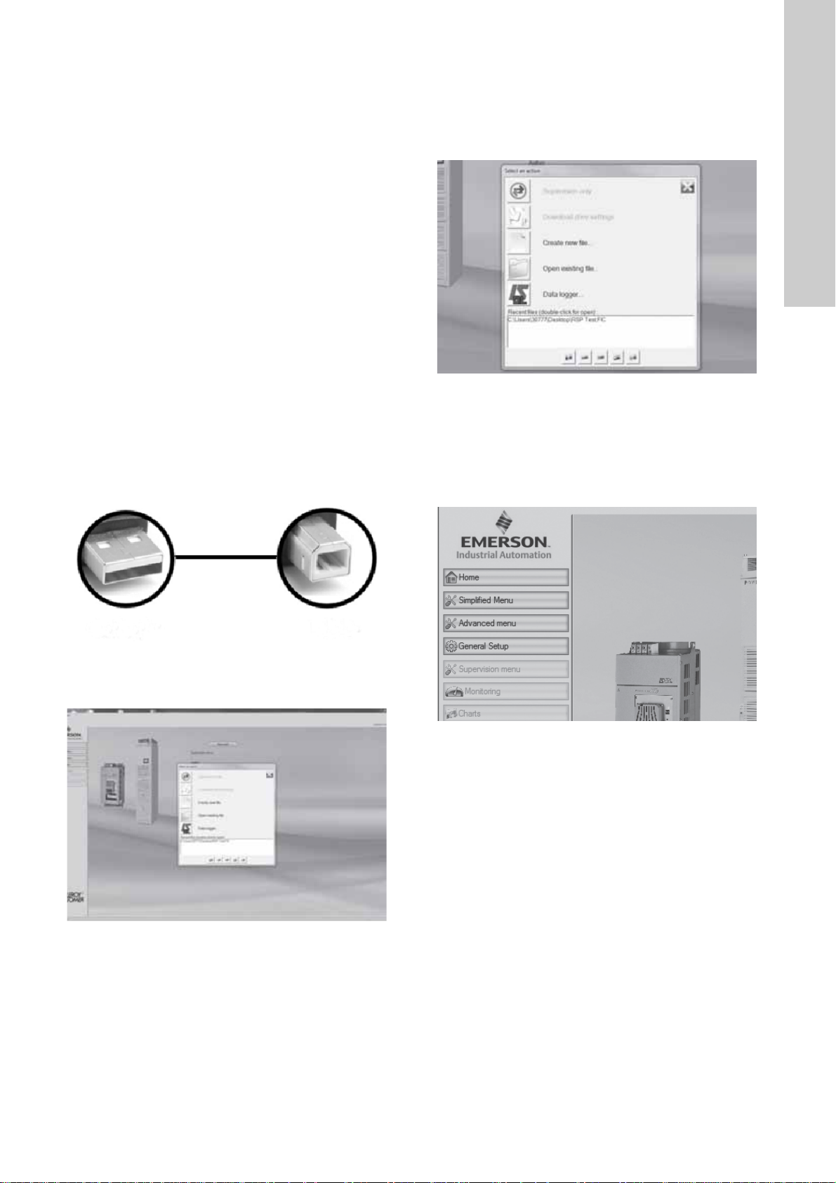
6. Software
USB-A USB-B
www.motralec.com / service-commercial@motralec.com / 01.39.97.65.10
In this section you find information about how to set parameters
via PC.
6.1 Grundfos BMS hs
Find the newest setting software at the Leroy-Somer website:
http://www.emersonindustrial.com.
6.1.1 POWERDRIVE FX, MD and MD2
With MDX-SOFT, setting parameters and supervising the
POWERDRIVE from a PC is very user-friendly.
Numerous functions are available:
• quick commissioning with the simplified menu
• file saving
• help file
• comparison of two files or one file with the factory settings
• supervision in table or progress bar form
• diagnostics
• representation of parameters in a table.
You can download the MDX-SOFT software from the Internet at
the following address: http://www.leroy-somer.com/fr/
telechargements/logiciels/
To connect the PC to the POWERDRIVE, use an
"MDXUSBIsolator" isolated USB kit.
Procedure:
1. Connect the PC (USB-A) to the POWERDRIVE controller
(USB-B) via the USB connection. The communication is ready
when you can read the "USB" on the display of the red
indicator light
3. Select an action
– "Supervision only"
– "Download drive settings"
– "Create new file"
– "Open existing file"
– "Data logger".
4. Select the needed action menu
– "Simplified menu"
– "Advanced menu"
– "General setup"
– "Supervision menu"
– "Monitoring"
– "Charts".
English (GB)
TM06 4597 2515TM06 4597 2515
2. Start up the MDX commissioning software. Use the help menu
displayed as a "?". Here you find a guide on how to use the
program.
TM06 3929 1215TM06 4597 2515
5. Save the changes and exit the program.
6. Remove the USB connection.
6.2 Grundfos BMS hp
Grundfos BMS hp is setup by factory. The settings are default
settings for a Grundfos BMSX application.
You can change the user specific parameters (duty point etc.) via
either:
•Grundfos R100
• Grundfos PC tool link
• Grundfos GO.
For further information, see the installation and operating
instructions for Grundfos MGE.
13
Page 14

7. Pressure exchanger
www.motralec.com / service-commercial@motralec.com / 01.39.97.65.10
English (GB)
The pressure exchanger requires no maintenance.
Warning
The water flow through the pressure exchanger
must not exceed rated flow.
See the pressure exchanger nameplate.
Warning
If you detect an abnormal sound, do not
dismantle the unit. This action can void the
warranty. Instead, call Grundfos Service.
You find information about the pressure exchanger on this
website: http://www.energyrecovery.com.
8. Fault finding
8.1 BMS hs and BMST
Warning
Before starting work on the product, make sure
that the power supply has been switched off and
that it cannot be accidentally switched on.
Fault Possible cause Remedy
1. The pump starts or
stops occasionally
during operation.
2. The pump stops during
operation.
3. The pump runs, but
generates no pressure
and delivers no water.
4. The pump runs at
reduced capacity.
a) No water supply.
The low-pressure switch has cut out.
a) The fuses are blown. Check all fuses in the control circuit. Replace defective
b) The frequency converter has tripped. Reset the frequency converter.
c) The motor/supply cable is defective. Check the motor and cable.
a) No or insufficient water supply to the pump. Check that the inlet pressure during operation is at least
b) The piping system, pump or nozzle is
choked up.
c) The prefilter is choked up. Clean the prefilter.
d) The valves on the discharge side are partly
closed or blocked.
e) The discharge pipe is partly blocked by
impurities.
f) The pump is partly blocked by impurities. Pull the pump out of the sleeve. Dismantle, clean and
g) The pump is defective. Pull the pump out of the sleeve. Dismantle, clean and
h) The prefilter is choked up. Clean the prefilter.
Check that the low-pressure switch functions normally
and is adjusted correctly. Check that the minimum inlet
pressure is correct. If not, check the feed pump. See
section BMS hs startup in the BMS hp, BMS hs
installation and operation instructions (publication
number 98567337).
fuses. After a cut-out, find the cause of a possible short
circuit.
If the fuses are hot when you replace them, check that
the load of the individual phases does not exceed the
motor current during operation. Identify the cause of the
load.
1 bar for BMS hs and 2 bar for BMST. If so, the water
supply is OK. Stop and vent the system.
Restart the pump as described in sections BMS hs
startup, BMS hp startup and Startup in the BMS hp,
BMS hs installation and operation instructions
(publication number 98567337). Check the functioning
of the pump.
Check the piping system, pump and nozzle.
Check the valves.
Clean or replace the discharge pipe. Measure the
discharge pressure, and compare the value with the
calculated data. See the "Technical specifications"
supplied with the system.
check the pump. Replace any defective parts.
check the pump. Replace any defective parts.
14
Page 15

8.2 BMS hp
www.motralec.com / service-commercial@motralec.com / 01.39.97.65.10
Warnin g
Before starting work on the product, make sure
that the power supply has been switched off and
that it cannot be accidentally switched on.
Fault Possible cause Remedy
1. The pump stops
occasionally during
operation.
2. The pump does not run. a) The fuses are blown. Check all fuses in the control circuit. Replace defective
3. The pump runs, but
generates no pressure
and delivers no water.
4. The pump runs at
reduced capacity (flow
and pressure).
a) No or insufficient water supply.
The pressure switch has cut out.
b) The capacity is too small. The flow switch
has cut out.
b) The frequency converter has tripped. Reset the unit.
c) The motor/supply cable is defective. Check the motor and cable. See section Electrical
a) No or insufficient water supply to the pump
or air in the system.
b) The suction parts are blocked. Pull the pump out of the sleeve, and clean the suction
c) The valves on the discharge side are partly
closed or blocked.
d) The discharge pipe is partly blocked by
impurities.
e) The pump is partly blocked by impurities. Pull the pump out of the sleeve. Dismantle, clean and
f) The pump is defective. Pull the pump out of the sleeve. Dismantle, clean and
Check that the pressure switch functions normally
without delay and is adjusted correctly. Check that the
minimum inlet pressure is correct.
The discharge pipe is totally or partly blocked due to
incorrect adjustment of a manually operated valve or
failure in the solenoid valve or the motor-operated valve.
Check these valves.
The flow switch is faulty or incorrectly adjusted.
Check and adjust the switch.
fuses. After a cut-out, find the cause of a possible short
circuit.
If the fuses are hot when you replace them, check that
the load of the individual phases does not exceed the
motor current during operation. Identify the cause of the
load.
If the fuses are not hot immediately after the cut-out,
identify the cause of a possible short circuit.
installation in the BMS hp, BMS hs installation and
operation instructions (publication number 98567337).
Check that the inlet pressure during operation is at least
1 bar. If so, the water supply is OK. Stop and vent the
system. Restart the system as described in section
BMSX system in the BMS hp, BMS hs installation and
operation instructions (publication number 98567337). If
the pump is defective, dismantle and repair or replace it.
parts.
Check the valves.
Measure the discharge pressure, and compare the value
with the calculated data. Clean or replace the discharge
pipe.
check the pump. Replace defective parts.
check the pump. Replace defective parts.
English (GB)
15
Page 16

8.3 Pressure exchanger
www.motralec.com / service-commercial@motralec.com / 01.39.97.65.10
English (GB)
Fault Possible cause Remedy
1. Excessive sound
pressure level.
2. Excessively high
recovery in the SWRO
system.
3. High salinity in the
high-pressure seawater
feed stream.
4. The low-pressure flow
is lower than the highpressure flow which
entails mixing and high
SWRO feed water
salinity.
5. Stalled rotor (no
audible rotation).
6. Low reject flow. a) Excessive pressure losses through the
Warnin g
Before starting work on the product, make sure
that the power supply has been switched off and
that it cannot be accidentally switched on.
a) The pressure exchanger operates above the
rated flow rates on the low-pressure side,
high-pressure side or both.
b) The pressure exchanger pump operates with
little or no backpressure.
c) Air in the system. Vent the system.
a) The BMS hs is operating at a flow rate that is
too high.
b) Increased salinity or raw-water temperature. Adjust flow rates in the system. See section BMSX
a) Unbalanced system. See section Startup in the BMS hp, BMS hs installation
b) A jammed or stalled rotor short-circuits the
high-pressure reject water with the highpressure feed water. No exchange occurs;
no audible rotation.
a) Operating pressure exchanger pumps below
the rated flow rate results in low rotor
rotation and increased mixing.
b) Malfunctioning and/or stalled BMS hp pump. Check the rotation, operation, flow rates and pressures
a) The system operates above the rated
pressure or below the rated flow capacity.
b) Debris or foreign particles in the device. Contact Grundfos Service.
c) The system is not properly flow-balanced. See section Startup in the BMS hp, BMS hs installation
SWRO system.
b) Malfunctioning and/or stalled BMS hp pump. Check the operation, flow rates and pressures of the
Immediately reduce the flow rate by adjusting the BMS
hp pump and control valve (V2). Rebalance the system
as described in section Startup in the BMS hp, BMS hs
installation and operation instructions (publication
number 98567337).
To increase the system capacity, add the pressure
exchanger pump(s) in parallel to the existing pumps.
Increase the backpressure by adjusting the lowpressure reject-water valve (V3).
Rebalance the system as described in section Startup in
the BMS hp, BMS hs installation and operation
instructions (publication number 98567337).
Check that the main BMS hs flow rate does not exceed
the membrane array production capacity for a given
temperature, salinity and fouling factor.
system in the BMS hp, BMS hs installation and
operation instructions (publication number 98567337).
and operation instructions (publication number
98567337).
See fault number 5.
Increase and balance the flows through the pressure
exchanger pump. Do not exceed the recommended
maximum flow rates. To increase the system capacity,
add pressure exchanger pump(s) in parallel to the
existing pumps. See section Startup in the BMS hp,
BMS hs installation and operation instructions
(publication number 98567337).
of the BMS hp pump.
See section Startup in the BMS hp, BMS hs installation
and operation instructions (publication number
98567337).
and operation instructions (publication number
98567337).
Contact Grundfos Service.
BMS hp pump.
16
Page 17
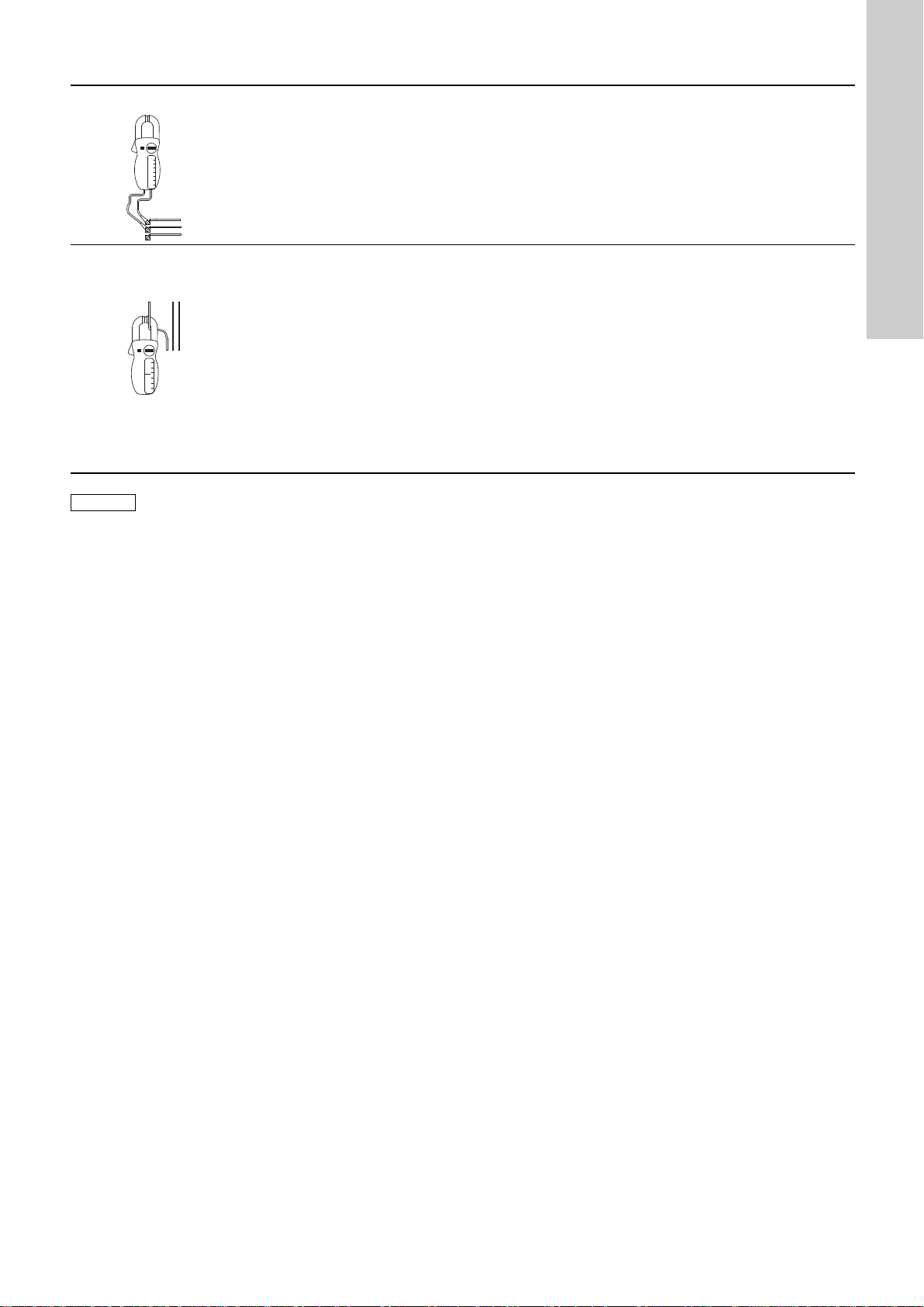
9. Checking the motor and cable
Note
www.motralec.com / service-commercial@motralec.com / 01.39.97.65.10
1. Supply voltage
2. Current consumption
Do not perform a standard insulation test (high
voltage test).
Measure the voltage between the phases with
a voltmeter.
Connect the voltmeter to the terminals of the
frequency converter.
TM00 1371 3597
Measure the current of each phase while the
pump is operating at a constant discharge
pressure, if possible at the capacity where the
motor is most heavily loaded.
For information on the normal operating
current, see the "Technical specifications".
TM00 1372 3597
When the motor is loaded, the voltage must be within ±
5 % of the rated voltage. If the voltage varies more
than that, the motor may burn.
If the voltage is constantly too high or too low, replace
the motor by a motor that corresponds to the supply
voltage.
Large variations in the supply voltage indicate poor
power supply, stop the pump until the defect has been
found.
It may be necessary to reset the frequency converter.
The difference between the current of the phase with
the highest amp consumption and the one with the
lowest current consumption must not exceed 10 % of
the lowest current consumption.
If the difference exceeds 10 % of the lowest current
consumption, or if the current exceeds the full-load
current, check these possible faults:
• A damaged pump is causing the motor to be
overloaded. Pull the pump out of the sleeve for
overhaul.
• The motor windings are short-circuited or partly
disjointed.
• Too high or too low supply voltage.
• Poor connection in leads. Weak cables.
English (GB)
17
Page 18

English (GB)
345a
www.motralec.com / service-commercial@motralec.com / 01.39.97.65.10
10. Drawings
TM06 3928 1315
18
Page 19

English (GB)
www.motralec.com / service-commercial@motralec.com / 01.39.97.65.10
TM06 1386 2314
19
Page 20

11. Data report, POWERDRIVE
Date of intervention Pump Start Date
Drive Serial No. Failure Date
Motor Serial No. Total Hours
Part No. of failed parts: Drive Type / Model:
Status preceding trip (#17.11) Trip history Trip Date & Time
Status at trip (#17.12) Trip 1 (#10.20) (#17.18 & #17.19)
Time between states (#17.13) Trip 2 (#10.21) (#17.20 & #17.21)
Minimum supply voltage (#17.31) Trip 3 (#10.22) (#17.22 & #17.23)
Maximum U,V,W temperature (#17.34) Trip 4 (#10.23) (#17.24 & #17.25)
Average DC BUS Voltage (#17.38) Trip 5 (#10.24) (#17.26 & #17.27)
Average Motor Speed (#17.39) Trip 6 (#10.25) N/A
Average Motor Current (#17.40) Trip 7 (#10.26) N/A
IGBT W av. Temp (#17.44) Trip 8 (#10.27) N/A
Rectifier av. Temp (#17.45) Trip 9 (#10.28) N/A
Average supply Voltage (#17.48) Trip 10 (#10.29) N/A
All 3-Phase wiring connections checked? Yes No Fast fuses damaged? Yes No
All motor connections checked? Yes No
PROCEED TO A CONTROL AND INTERFACE BOARD TEST
(#17.01 = Yes)
AND INDICATE THE TEST RESULT
(#17.05)
Processing Passed
Control Interface None
PROCEED TO A POWER MODULE TEST
(#17.02 = Yes)
AND INDICATE THE POWER MODULE TEST RESULT
(#17.06)
Passed (1)
Error Motor (6)
Error U Phase (2)
Error U & V Phase (7)
Error V Phase (3)
Error V & W Phase (8)
Error W Phase (4)
Error U & W Phase (9)
Error Rectifier (5)
Error STO not connected (10)
Error code (#17.08)
Refer to the commissioning manual (#17.06) for error code details / comments
Winding insulation measurement > 20 M
Phase U
- Phase V - Phase W
Winding Resistance Measurement
U / V phases : - V / W phases : - U / W phases :
Return No. Warranty? Yes No
Test Engineer Date Issued
Comments:
Investigation Details:
www.motralec.com / service-commercial@motralec.com / 01.39.97.65.10
English (GB)
To be completed by the Grundfos Service Technician servicing the equipment – complete all questions.
Trip Log Details
General Checks
Powerdrive Diagnostics
Motor Checks
Site technician comments:
Warranty Department Use Only
TM06 3930 1215
20
 Loading...