

Grundfos AP70, APG Series, APG.50.11.1, APG.50.18.1, APG.50.12.1 Installation And Operating Instructions Manual
...Page 1
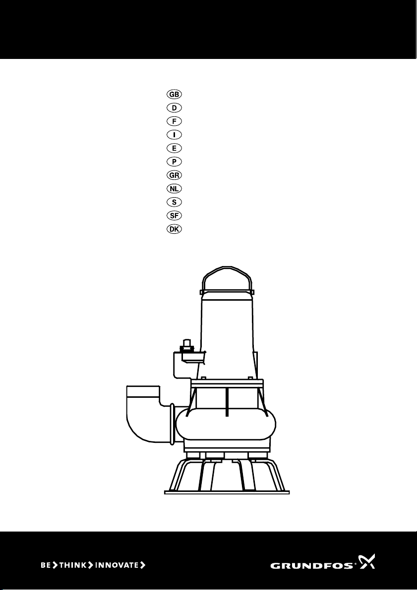
GRUNDFOS INSTRUCTIONS
AP70
Installation and operating instructions
Montage- und Betriebsanleitung
Notice d’installation et d’entretien
Istruzioni di installazione e funzionamento
Instrucciones de instalación y funcionamiento
Instruções de instalação e funcionamento
œ‰Á„flВЪ В„Н·Щ‹ЫЩ·ЫБЪ Н·И ОВИЩФıÒ„fl·Ú
Installatie- en bedieningsinstructies
Monterings- och driftsinstruktion
Asennus- ja käyttöohjeet
Monterings- og driftsinstruktion
Page 2

We GRUNDFOS declare under our sole responsibility that the products AP70, to which this declaration relates, are in conformity with
the Council Directives on the approximation of the laws of the EEC
Member States relating to
– Machinery (98/37/EEC).
– Electromagnetic compatibility (89/336/EEC).
– Electrical equipment designed for use within certain voltage
Nous GRUNDFOS déclarons sous notre seule responsabilité que
les produits AP70 auxquels se réfère cette déclaration sont conformes aux Directives du Conseil concernant le rapprochement des
législations des Etats membres CEE relatives à
– Machines (98/37/CEE).
– Compatibilité électromagnétique (89/336/CEE).
– Matériel électrique destiné à employer dans certaines limites de
Nosotros GRUNDFOS declaramos bajo nuestra única responsabilidad que los productos AP70 a los cuales se refiere esta declaración
son conformes con las Directivas del Consejo relativas a la aproximación de las legislaciones de los Estados Miembros de la CEE
sobre
– Máquinas (98/37/CEE).
– Compatibilidad electromagnética (89/336/CEE).
– Material eléctrico destinado a utilizarse con determinadas lími-
≈ÏÂflÚ Á GRUNDFOS ‰ÁβÌÔıПВ ПВ ·рФНОВИЫЩИН‹ ‰ИН fi Ï·Ú
ÂıË˝ÌÁ ¸ÙÈ Ù· ðÒÔȸÌÙ · AP70 ÛıÏÏÔÒˆ˛ÌÔÌÙ·È Ï ÙÁÌ œ‰Á„fl ·
ÙÔı ”ıÏ‚ÔıÎ flÔı Âðfl ÙÁ Ú Û˝„НОИЫБЪ Щ˘Ì Ì¸Ï˘Ì Ù˘Ì Ò·Ù˛Ì MÂβÌ
ÙÁÚ ≈ıÒ˘ð·ÈÍfiÚ ≈Ì ˘ÛÁÚ Û ۘ›ÛÁ Ï ٷ
ñÃÁ˜·ÌfiÏ·Ù· (98/37/EEC).
с«ОВНЩТФП·„МБЩИНfi ÛıÏ‚·Ù¸ÙÁÙ· (89/336/EEC).
– «ОВНЩТИН›Ъ Ыı ÛÍÂı›Ú ۘ‰ȷÛÏ› ÌÂÚ „È‹ ˜ÒfiÛÁ ÂÌÙ¸Ú
Vi GRUNDFOS försäkrar under ansvar, att produkterna AP70, som
omfattas av denna försäkran, är i överensstämmelse med Rådets
Direktiv om inbördes närmande till EU-medlemsstaternas lagstiftning, avseende
– Maskinell utrustning (98/37/EC).
– Elektromagnetisk kompatibilitet (89/336/EC).
– Elektrisk material avsedd för användning inom vissa spännings-
Vi GRUNDFOS erklærer under ansvar, at produkterne AP70, som
denne erklæring omhandler, er i overensstemmelse med Rådets
direktiver om indbyrdes tilnærmelse til EF medlemsstaternes lovgivning om
– Maskiner (98/37/EØF).
– Elektromagnetisk kompatibilitet (89/336/EØF).
– Elektrisk materiel bestemt til anvendelse inden for visse
Declaration of Conformity
Standard used: EN 292.
Standards used: EN 61 000-6-2 and EN 61 000-6-3.
limits (73/23/EEC).
Standards used: EN 60 335-1 and EN 60 335-2-41.
Déclaration de Conformité
Standard utilisé: EN 292.
Standards utilisés: EN 61 000-6-2 et EN 61 000-6-3.
tension (73/23/CEE).
Standards utilisés: EN 60 335-1 et EN 60 335-2-41.
Declaración de Conformidad
Norma aplicada: EN 292.
Normas aplicadas: EN 61 000-6-2 y EN 61 000-6-3.
tes de tensión (73/23/CEE).
Normas aplicadas: EN 60 335-1 y EN 60 335-2-41.
ƒfi΢ÛÁ ”ıÏϸ҈˘ÛÁÚ
—Ò¸ÙıðÔ ðÔı ˜ТБЫИПФрФИfiËÁÍÂ: EN 292.
—Ò¸Ùıð· ðÔı ˜ТБЫИПФрФИfiËÁÍ·Ì: EN 61 000-6-2 Í·È
EN 61 000-6-3.
ФТИЫП›М˘Ì ÔÒfl˘М БОВНЩТИНfi
—Ò¸Ùıð· ðÔı ˜ТБЫИПФрФИfiËÁÍ·Ì: EN 60 335-1 Í·È
EN 60 335-2-41.
Ú Ù‹ÛÁÚ (73/23/EEC).
Försäkran om överensstämmelse
Använd standard: EN 292.
Använda standarder: EN 61 000-6-2 och EN 61 000-6-3.
gränser (73/23/EC).
Använda standarder: EN 60 335-1 och EN 60 335-2-41.
Overensstemmelseserklæring
Anvendt standard: EN 292.
Anvendte standarder: EN 61 000-6-2 og EN 61 000-6-3.
spændingsgrænser (73/23/EØF).
Anvendte standarder: EN 60 335-1 og EN 60 335-2-41.
Wir GRUNDFOS erklären in alleiniger Verantwortung, daß die Produkte AP70, auf die sich diese Erklärung bezieht, mit den folgenden
Richtlinien des Rates zur Angleichung der Rechtsvorschriften der
EG-Mitgliedstaaten übereinstimmen:
– Maschinen (98/37/EWG).
Norm, die verwendet wurde: EN 292.
– Elektromagnetische Verträglichkeit (89/336/EWG).
Normen, die verwendet wurden: EN 61 000-6-2 und
EN 61 000-6-3.
– Elektrische Betriebsmittel zur Verwendung innerhalb bestimmter
Spannungsgrenzen (73/23/EWG).
Normen, die verwendet wurden: EN 60 335-1 und
EN 60 335-2-41.
Noi GRUNDFOS dichiariamo sotto la nostra esclusiva responsabilità
che i prodotti AP70 ai quali questa dichiarazione si riferisce sono
conformi alle Direttive del Consiglio concernente il ravvicinamento
delle legislazioni degli Stati membri CEE relative a
– Macchine (98/37/CEE).
Standard usato: EN 292.
– Compatibilità elettromagnetica (89/336/CEE).
Standard usati: EN 61 000-6-2 e EN 61 000-6-3.
– Materiale elettrico destinato ad essere utilizzato entro certi limiti
di tensione (73/23/CEE).
Standard usati: EN 60 335-1 e EN 60 335-2-41.
Nós GRUNDFOS declaramos sob nossa única responsabilidade
que os produtos AP70 aos quais se refere esta declaração estão em
conformidade com as Directivas do Conselho das Comunidades
Europeias relativas à aproximação das legislações dos Estados
Membros respeitantes à
– Máquinas (98/37/CEE).
Norma utilizada: EN 292.
– Compatibilidade electromagnética (89/336/CEE).
Normas utilizadas: EN 61 000-6-2 e EN 61 000-6-3.
– Material eléctrico destinado a ser utilizado dentro de certos limi-
tes de tensão (73/23/CEE).
Normas utilizadas: EN 60 335-1 e EN 60 335-2-41.
Wij GRUNDFOS verklaren geheel onder eigen verantwoordelijkheid
dat de produkten AP70 waarop deze verklaring betrekking heeft in
overeenstemming zijn met de Richtlijnen van de Raad inzake de
onderlinge aanpassing van de wetgevingen van de Lid-Staten
betreffende
– Machines (98/37/EEG).
Norm: EN 292.
– Elektromagnetische compatibiliteit (89/336/EEG).
Normen: EN 61 000-6-2 en EN 61 000-6-3.
– Elektrisch materiaal bestemd voor gebruik binnen bepaalde
spanningsgrenzen (73/23/EEG).
Normen: EN 60 335-1 en EN 60 335-2-41.
Me GRUNDFOS vakuutamme yksin vastuullisesti, että tuotteet
AP70, jota tämä vakuutus koskee, noudattavat direktiivejä jotka
käsittelevät EY:n jäsenvaltioiden koneellisia laitteita koskevien lakien yhdenmukaisuutta seur.:
– Koneet (98/37/EY).
Käytetty standardi: EN 292.
– Elektromagneettinen vastaavuus (89/336/EY).
Käytetyt standardit: EN 61 000-6-2 ja EN 61 000-6-3.
– Määrättyjen jänniterajoitusten puitteissa käytettävät sähköiset
laitteet (73/23/EY).
Käytetyt standardit: EN 60 335-1 ja EN 60 335-2-41.
Bjerringbro, 1st May 2002
Konformitätserklärung
Dichiarazione di Conformità
Declaração de Conformidade
Overeenkomstigheidsverklaring
Vastaavuusvakuutus
Kenth Hvid Nielsen
Technical Manager
Page 3
AP70
Installation and
operating instructions
Montage- und
Betriebsanleitung
Notice d’installation
et d’entretien
Istruzioni di installazione
e funzionamento
Instrucciones de instalación
y funcionamiento
Instruções de instalação
e funcionamento
œ‰Á„flВЪ В„Н·Щ‹ЫЩ·ЫБЪ
Н·И ОВИЩФıÒ„fl·Ú
Page 4
Seite 8
Page 14
Pag. 19
Pág. 23
Pág. 27
”ÂÎfl‰· 31
Installatie- en
bedieningsinstructies
Monterings- och
driftsinstruktion
Asennus- ja
käyttöohjeet
Monterings- og
driftsinstruktion
Pag. 36
Sida 40
Sivu 44
Side 48
3
Page 4
CONTENTS
Page
1. General description 4
1.1 Applications 4
1.2 Operating conditions 4
1.3 Sound pressure level 4
2. Safety 4
3. Transportation and storage 4
4. Installation 4
4.1 Installation on auto-coupling 4
4.2 Free-standing installation 5
4.3 Pumps supplied with control box 5
4.4 Separate level controllers 5
5. Electrical connection 5
5.1 Motor protection 5
6. Start-up 6
6.1 Direction of rotation 6
7. Maintenance and service 6
7.1 Contaminated pumps 6
8. Fault finding chart 7
9. Disposal 7
1.2.2 Liquid temperature
Liquid temperature: 0°C to +40°C.
For short periods up to +60°C.
1.2.3 Density of pumped liquid
Maximum density of pumped liquid: 1100 kg/m3.
1.2.4 Installation depth
Maximum 10 metres below liquid level.
1.2.5 Level of pumped liquid
The lowest stop level must always be above the top
of the pump housing.
1.2.6 Operation
Maximum 15 starts per hour.
Note: The pumps are designed for intermittent oper-
ation only.
1.3 Sound pressure level
The sound pressure level of the pump is lower than
the limiting values stated in the EC Council Directive
98/37/EEC relating to machinery.
Before beginning installation procedures,
these installation and operating instructions should be studied carefully. The installation and operation should also be in
accordance with local regulations and accepted codes of good practice.
1. General description
1.1 Applications
GRUNDFOS AP70 pumps are designed for pumping:
• wastewater,
• sludge-containing water,
• groundwater,
• sewage from restaurants, hotels, camping sites,
etc.
The compact design makes the pumps suitable for
both temporary and permanent installation. Furthermore, the pumps are suitable for free-standing installation as well as installation by means of an autocoupling guide rail system.
1.1.1 Explosive environments
Use the explosion-proof AP pump versions for applications involving the risk of explosion.
Note: In each individual case the explosion classification of the pump must be approved by the local
authorities for use at the desired installation site.
1.2 Operating conditions
1.2.1 pH-value
AP pumps in permanent installations can cope with
pH-values ranging from 4 to 10.
2. Safety
Pump installation in wells must be carried
out by specially trained persons.
3. Transportation and storage
The pump may be transported and stored in a vertical or horizontal position. Make sure that it cannot
roll or fall over.
Always lift the pump by its carrying handle, never by
the motor cable or the hose/pipe.
For long periods of storage, the pump must be protected against moisture and heat.
After a long period of storage, the pump should be
inspected before it is put into operation. Make sure
that the impeller can rotate freely. Pay special attention to the shaft seals and the cable entry.
4. Installation
The loose nameplate supplied with the pump should
be fixed at the installation site.
Prior to installation, check the oil level in the oil
chamber, see section 7. Maintenance and service.
4.1 Installation on auto-coupling
See figs. A and B, pages 52 and 53.
Pumps for permanent installation can be installed on
a stationary auto-coupling and operated completely
or partially submerged in the pumped liquid.
1. Drill mounting holes for guide rail bracket on the
inside of the pit and fasten the guide rail bracket
provisionally with two screws.
4
Page 5

2. Place the auto-coupling base unit on the bottom
of the pit. Use a plumb line to establish the correct positioning. Fasten with heavy-duty expansion bolts. If the bottom of the pit is uneven, the
auto-coupling base unit must be supported so
that it is level when being fastened.
3. Assemble the discharge line in accordance with
the generally accepted procedures and without
exposing the line to distortion or tension.
4. Insert the guide rails in the rings of the auto-coupling base unit and adjust the length of the rails
accurately to the guide rail bracket.
5. Unscrew the provisionally fastened guide rail
bracket, fit it on top of the guide rails and finally
fasten it firmly to the pit wall.
Note: The guide rails must not have any axial play
as this would cause noise during pump operation.
6. Clean out debris from the pit before lowering the
pump into the pit.
7. Fit the auto-coupling half on to the discharge port
of the pump. Then slide the guide bar of this coupling half between the guide rails and lower the
pump into the pit by means of a chain. When the
pump reaches the auto-coupling base unit, the
pump will automatically connect tightly.
8. Hang up the end of the chain on a suitable hook
at the top of the pit.
9. Adjust the length of the motor cable by coiling it
up on a relief fitting, so the cable is not damaged
during operation. Fasten the relief fitting to a suitable bracket at the top of the pit. Make sure that
the cables are not sharply bent or pinched.
Note: The end of the cable must not be submerged,
as water may penetrate through the cable into the
motor.
4.2 Free-standing installation
See fig. C, page 54.
AP70 pumps should be provided with a separate
base stand.
For free-standing installation of the pumps, fit a 90°
elbow to the discharge port. The pump can be installed with a hose or rigid pipe and valves.
In order to facilitate service of the pump, fit a flexible
union or coupling to the discharge line for easy separation.
If a hose is used, make sure that the hose does not
buckle and that the inside diameter of the hose
matches that of the discharge port.
If a rigid pipe is used, the union or coupling, nonreturn valve and isolating valve should be fitted in
the sequence mentioned, as seen from the pump
side.
Lower the pump into the liquid.
If the pump is installed in muddy conditions or on un-
even ground, it is recommended to support the pump
on bricks.
4.3 Pumps supplied with control box
Pumps supplied with a control box may be supplied
with a level switch with cable. The level switch cable,
if supplied, should be fastened in the retainer on the
pump handle.
The difference in level between start and stop may
be adjusted by adjusting the free length of cable between the level switch and the retainer.
Large difference in level: Long cable.
Small difference in level: Short cable.
4.4 Separate level controllers
Three-phase AP pumps without control box or level
switch can be supplied with a separate level controller with level switches: Type LC for one-pump installations and type LCD for two-pump installations.
LC is fitted with two or three level switches. The third
level switch, which is optional, is for high-level alarm.
LCD is fitted with three or four level switches: one for
common stop and two for start of pumps. The fourth
level switch, which is optional, is for high-level alarm.
When installing the level switches, the following
points should be observed:
• To prev ent air intak e and vibrations, t he stop level
switch must be fitted in such a way that the pump
is stopped before the liquid level is lowered below
the top of the pump housing.
•The start level switch should be installed in such
a way that the pump is started at the required
level; however, the pump must always be started
before the liquid level reaches the bottom inlet
pipe in the pit.
•The high-level alarm switch, if installed, should
always be installed about 10 cm above the starting
level switch; however, alarm must always be given
before the liquid level reaches the inlet pipe to the
pit.
5. Electrical connection
The electrical connection of the pump should be carried out in accordance with local regulations.
The operating voltage and frequency are marked on
the nameplate. Voltage tolerance: ±10% of the voltage stated on the nameplate. Make sure that the motor is suitable for the electricity supply available at
the installation site.
5.1 Motor protection
All three-phase GRUNDFOS AP pumps supplied
without control box must be connected to a separate
motor starter. The explosion-proof pumps have a
thermal switch built into the motor windings. The
thermal switch is connected to the control circuit of
the motor starter, see fig. 1.
5
Page 6

Fig. 1
T1
VW
U
T2
PE
M
Max. 250 V/2.5 A
Max. 250V / 2.5 A
The separate control box/motor starter
must not be installed in explosive environments.
6. Start-up
Do not start up the pump until the system has been
filled with liquid and vented. Make sure that the
pump is submerged in the liquid, open the isolating
valves, if fitted, and check the setting of the level
switches.
Note: The pump may, however, be started for a very
short period without being submerged for checking
of the direction of rotation.
6.1 Direction of rotation
Before starting up three-phase pumps, check the direction of rotation. The direction of rotation should be
clockwise when viewed from above. When starting
up, the pump will jerk in the opposite direction to the
direction of rotation. If the direction of rotation is
wrong, interchange two of the three phases of the
electricity supply.
7. Maintenance and service
Before starting work on the pump, make
sure that the electricity supply has been
switched off and that it cannot be accidentally switched on. Furthermore, all rotating
parts must have stopped moving.
Before carrying out maintenance and service, make
sure that the pump has been thoroughly flushed with
clean water. Rinse the pump parts in water after dismantling.
When unscrewing the inspection screw of
the oil chamber, please note that pressure
may have built up in the chamber. Do not
remove the screw until the pressure has
been fully relieved.
Pumps running normal operation should be inspected at least once a year. If the pumped liquid is
very muddy or sandy, inspect the pump at shorter intervals.
When the pump is new or after replacement of the
shaft seals, check the oil level after one week of operation.
For long and trouble-free operation of the pump the
following points should be checked regularly:
• Power consumption
• Oil level and oil condition
The oil becomes greyish white like milk if it contains water. This may be the result of a defective
shaft seal. The oil should be replaced after 3000
hours of operation.
Use Shell Ondina 15 oil or similar type.
Note: Used oil must be disposed of in accordance
with local regulations.
The following table states how much oil the AP
pumps must have in the oil chamber:
TM00 1618 0693
Pump type
AP70.80.09.3 0.80 l
AP70.80.09.3Ex 0.80 l
AP70.80.13.3 0.80 l
AP70.80.13.3Ex 0.80 l
AP70.80.19.3 1.20 l
AP70.80.19.3Ex 1.20 l
AP70.80.24.3 1.20 l
AP70.80.24.3Ex 1.20 l
Ex = explosion-proof.
• Cable entry
Make sure that the cable entry is watertight and
that the cables are not bent sharply and/or
pinched.
• Pump par ts
Check the impeller, pump housing, neck ring, etc.
for possible wear. Replace defective parts.
• Ball bearings
Check the shaft for noisy or heavy operation (turn
the shaft by hand). Replace defective ball bearings.
A general overhaul of the pump is usually required
in case of defective ball bearings or poor motor
function. This work must be carried out by the
manufacturer or a competent workshop.
Quantity of oil in
oil chamber
7.1 Contaminated pumps
Note: If a pump has been used for a liquid which is
injurious to health or toxic, the pump will be classified as contaminated.
If GRUNDFOS is requested to service the pump,
GRUNDFOS must be contacted with details about
the pumped liquid, etc. before the pump is returned
for service. Otherwise GRUNDFOS can refuse to accept the pump for service.
Possible costs of returning the pump are paid by the
customer.
However, any application for service (no matter to
whom it may be made) must include details about
the pumped liquid if the pump has been used for liquids which are injurious to health or toxic.
6
Page 7

8. Fault finding chart
Make sure that all power supplies have been switched off and that all rotating parts have stopped
moving before attempting to diagnose any fault.
Fault Cause Remedy
1. Motor does not start. Fuses
blow or motor starter trips out
immediately.
Caution: Do not start again!
2. Pump operates, but motor
starter trips out after a short
while.
3. Pump operates at belowstandard performance and
power consumption.
4. Pump operates, but gives no
liquid.
a) Supply failure; short-circuit;
earth-leakage fault in cable or
motor winding.
b) Fuses blow due to use of wrong
type of fuse.
c) Impeller blocked by impurities. Clean the impeller.
d) Level switch out of adjustment
or defective.
a) Low setting of thermal relay in
motor starter.
b) Increased current consumption
due to large voltage drop.
c) Impeller blocked by impurities.
Increased current consumption
in all three phases.
a) Impeller blocked by impurities. Clean the impeller.
b) Wrong direction of rotation.
a) Discharge valve closed or
blocked.
b) Non-return valve blocked. Clean non-return valve.
Have the cable and motor checked
and repaired by a qualified electrician.
Install fuses of the correct type.
Check the level switch.
Set the relay in accordance with
the specifications on the nameplate.
Measure the voltage between motor phases. Tolerance: ±10%.
Clean the impeller.
Check the direction of rotation and
possibly interchange two phases,
see section 6.1 Direction of rota-
tion.
Check discharge valve and possibly open and/or clean.
Vent the pump.c) Air in pump.
9. Disposal
Disposal of this product or parts of it must be carried
out according to the following guidelines:
1. Use the local public or private waste collection
service.
2. In case such waste collection service does not
exist or cannot handle the materials used in the
product, please deliver the product or any hazardous materials from it to your nearest GRUNDFOS company or service workshop.
Subject to alterations.
7
Page 8

GB: 1-pump installation on auto-coupling
D: Eine Pumpe mit Autokupplung
F: Une pompe avec système d’accouplement automatique
I: Una pompa con accoppiamento rapido
E: Una bomba con autoacoplamiento
P: Uma bomba com acoplamento automático
GR: ∂ÁηٿÛÙ·ÛË ÌÈ¿˜ ·ÓÙÏ›·˜ Ì ·˘ÙfiÌ·ÙË ˙‡ÍË
NL: Eén pomp met voetbochtsnelkoppeling
S: En pump installerad med kopplingsfot
SF: Yhden pumpun asennus jalustaliittimellä
DK: En pumpe med auto-kobling
Fig. A
A
C
F
T
E
S
‹
‹
‹
‹
‹
‹
‹
‹
‹
‹
‹
‹
‹
‹
‹
‹
‹
‹
‹
‹
‹
‹
‹
V
U
‹
‹
‹
‹
‹
‹
‹
‹
‹
‹
‹‹‹
‹
‹
‹
‹
‹
‹
‹
‹
‹
‹
‹
‹
‹
‹
‹
‹
‹
‹
‹
‹
‹
‹
‹
‹
‹
‹
‹
‹
‹
‹
‹‹
‹
‹
‹
‹
‹
‹
‹
‹
‹
‹
‹
‹
‹
‹
‹
‹
‹
‹
‹
‹
‹
‹
‹
‹
‹
‹
‹
‹
‹
‹‹‹
‹
‹
‹
‹
‹
‹
‹
‹
‹
‹
‹
‹‹‹
‹
‹
‹
‹
‹
‹
‹
‹
‹
‹
‹
‹
‹
‹
‹
‹
‹
‹
‹
‹
‹
‹
‹
‹‹
‹
‹
‹
‹
‹
‹
‹
‹
‹
‹
‹
G
H
K
L
ON
A B C D E F G H I J
ø600 ø600 340 340 83 87 123 87 270 100
K L M N O P R S T U V
243 645 200 550 950 690 – DN80 1½” 190 335
52
J
TM01 2580 2098
Page 9

GB: 2-pump installation on auto-coupling
D: Zwei Pumpen mit Autokupplung
F: Deux pompes avec système d’accouplement automatique
I: Due pompe con accoppiamento rapido
E: Dos bombas con autoacoplamiento
P: Duas bombas com acoplamento automático
GR: ∂БО·Щ¿ЫЩ·ЫЛ ‰‡Ф ·УЩПИТУ МВ ·˘ÙfiÌ·ÙË ˙‡ÍË
NL: Tvee pompen met voetbochtsnelkoppeling
S: Två pumpar installerade med kopplingsfot
SF: Kahden pumpun asennus jalustaliittimellä
DK: To pumper med auto-kobling
Fig. B
B
D
‹
‹
‹
‹
‹
‹
‹
‹
‹
‹
‹
‹
‹
‹
‹
‹
‹
‹
‹
‹
‹
‹
‹
‹
‹
‹
‹
‹
‹
‹
‹
‹
‹
‹
‹
‹
‹
‹
‹
‹
‹
‹
‹
‹
‹
‹
‹
‹
‹
‹
‹
‹
‹
‹
‹
‹
‹
‹
‹
‹
‹
‹
‹
‹
‹
‹
‹
‹
‹
‹
‹
‹
‹
‹
‹
‹
‹
‹
‹
‹
‹
‹
‹
‹
‹
‹
‹
‹
‹
‹
‹
‹
‹‹‹
‹
‹
‹
‹
‹
‹
‹
‹
‹
‹
‹
‹
‹
‹
‹
‹
‹
‹
‹
‹
‹
‹
‹
‹
‹
‹
‹
‹‹‹
‹
‹
‹
‹
‹
‹
‹
‹
‹
‹
‹
‹
‹
‹
‹
‹
‹
‹
‹
‹
‹
‹
‹
‹
‹
‹
‹
‹
‹
‹
‹
‹
‹
‹
‹
‹
‹
‹
‹
‹
‹
‹
‹
‹
‹
‹
‹
‹
‹
‹‹
‹
‹
‹
‹
‹
‹
‹
‹
‹
‹
‹
‹
‹
‹
‹
‹
‹
‹
‹
‹
‹
‹
‹
‹
‹
‹
‹
‹
‹
‹
‹
‹
‹
‹
‹
‹
‹
‹
‹
‹
I
M M
P R P
A B C D E F G H I J
600 1300 340 340 83 87 123 87 270 100
K L M N O P R S T U V
243 645 200 820 1180 690 620 DN80 1½” 190 335
‹
‹
‹
‹
‹
‹
‹
‹
‹
‹
‹
‹
‹
‹
‹
‹
‹
‹
‹
‹
‹
‹
‹
‹
‹
‹
‹
‹
‹
‹
‹
‹
‹
‹
‹
‹
‹
‹
‹
‹
‹
‹
‹
‹
‹
‹
‹
‹
‹
‹
‹
‹
‹
‹
‹
‹
‹
‹
‹
‹
‹
‹
‹
‹
‹
‹
‹
‹
‹
‹
‹
‹
‹
‹
‹
‹
‹
‹‹‹
‹
‹
‹
‹
‹
‹
‹
‹
‹
‹
‹
‹
‹
‹
‹
‹
‹
‹
‹
‹
‹
‹
‹
‹
‹
‹‹‹
‹
‹
‹
‹
‹
‹
‹
‹
‹
‹
‹
‹
‹
‹
‹
‹
‹
‹
‹
‹
‹
‹
‹
‹
‹
‹
‹
‹
‹
‹
‹
‹
‹
‹
‹‹
‹
‹
‹
‹
‹
‹
‹
‹
‹
‹
‹
‹
TM01 2581 2098
53
Page 10

GB: Free-standing Installation
D: Freistehender Einbau
F: Installation fixe sur socle
I: Installazione su piede d’appoggio
E: Instalación portátil
P: Instalação autónoma
GR: ∞УВН¿ЪЩЛЩЛ ВБО·Щ¿ЫЩ·ЫЛ
NL: Vrijstaande opstelling
S: Fristående installation
SF: Vapaasti seisova asennus
DK: Fritstående installation
Fig. C
S
A
E
C
S
A
E
D
D
B
TM01 2579 2098
AP70 A B C D E F S
AP70.80.09.3 586 418 180 90 278 – R 3
AP70.80.09.3Ex 586 418 180 90 278 – R 3
AP70.80.13.3 586 418 180 90 278 – R 3
AP70.80.13.3Ex 586 418 180 90 278 – R 3
AP70.80.19.3 663 580 218 125 327 398 R 3
AP70.80.19.3Ex 663 580 218 125 327 398 R 3
AP70.80.24.3 663 580 218 125 327 398 R 3
AP70.80.24.3Ex 663 580 218 125 327 398 R 3
F
B
C
TM01 2568 2098
54
Page 11

Denmark
GRUNDFOS DK A/S
Poul Due Jensens Vej 7A
DK-8850 Bjerringbro
Tlf.: +45-87 50 50 50
Telefax: +45-87 50 51 51
Argentina
Bombas GRUNDFOS de Argentina S.A.
Ruta Panamericana km. 37.500
Lote 34A
1619 - Garin
Pcia. de Buenos Aires
Phone: +54-3327 414 444
Telefax: +54-3327 411 111
Australia
GRUNDFOS Pumps Pty. Ltd.
P.O. Box 2040
Regency Park
South Australia 5942
Phone: +61-8-8461-4611
Telefax: +61-8-8340 0155
Austria
GRUNDFOS Pumpen Vertrieb
Ges.m.b.H.
Grundfosstraße 2
A-5082 Grödig/Salzburg
Tel.: +43-6246-883-0
Telefax: +43-6246-883-30
Belgium
N.V. GRUNDFOS Bellux S.A.
Boomsesteenweg 81-83
B-2630 Aartselaar
Tél.: +32-3-870 7300
Télécopie: +32-3-870 7301
Brazil
GRUNDFOS do Brasil Ltda.
Rua Tomazina 106
CEP 83325 - 040
Pinhais - PR
Phone: +55-41 668 3555
Telefax: +55-41 668 3554
Canada
GRUNDFOS Canada Inc.
2941 Brighton Road
Oakville, Ontario
L6H 6C9
Phone: +1-905 829 9533
Telefax: +1-905 829 9512
China
GRUNDFOS Pumps (Shanghai)
Co. Ltd.
22 Floor, Xin Hua Lian Building
755-775 Huai Hai Rd, (M)
Shanghai 200020
PRC
Phone: +86-512-67 61 11 80
Telefax: +86-512-67 61 81 67
Czech Republic
GRUNDFOS s.r.o.
Cajkovského 21
779 00 Olomouc
Phone: +420-68-5716 111
Telefax: +420-68-543 8908
Finland
OY GRUNDFOS Pumput AB
Mestarintie 11
Piispankylä
FIN-01730 Vantaa (Helsinki)
Phone: +358-9 878 9150
Telefax: +358-9 878 91550
France
Pompes GRUNDFOS Distribution S.A.
Parc d’Activités de Chesnes
57, rue de Malacombe
F-38290 St. Quentin Fallavier
(Lyon)
Tél.: +33-4 74 82 15 15
Télécopie: +33-4 74 94 10 51
Germany
GRUNDFOS GMBH
Schlüterstr. 33
40699 Erkrath
Tel.: +49-(0) 211 929 69-0
Telefax: +49-(0) 211 929 69-3799
e-mail: infoservice@grundfos.de
Service in Deutschland:
e-mail: kundendienst@grundfos.de
Greece
GRUNDFOS Hellas A.E.B.E.
20th km. Athinon-Markopoulou
Av.
P.O. Box 71
GR-19002 Peania
Phone: +30-10-66 83 400
Telefax: +30-10-66 46 273
Hong Kong
GRUNDFOS Pumps (Hong
Kong) Ltd.
Unit 1, Ground floor
Siu Wai Industrial Centre
29-33 Wing Hong Street &
68 King Lam Street, Cheung Sha
Wan
Kowloon
Phone: +852-27861706/
27861741
Telefax: +852-27858664
Hungary
GRUNDFOS Hungária Kft.
Park u . 8
H-2045 Törökbalint,
Phone: +36-34 520 100
Telefax: +36-34 520 200
India
GRUNDFOS Pumps India Private Limited
Flat A, Ground Floor
61/62 Chamiers Aptmt
Chamiers Road
Chennai 600 028
Phone: +91-44 432 3487
Telefax: +91-44 432 3489
Indonesia
PT GRUNDFOS Pompa
Jl. Rawa Sumur III, Blok III / CC1
Kawasan Industri, Pulogadung
Jakarta 13930
Phone: +62-21-460 6909
Telefax: +62-21-460 6910/460
6901
Ireland
GRUNDFOS (Ireland) Ltd.
Unit 34, Stillorgan Industrial Park
Blackrock
County Dublin
Phone: +353-1-2954926
Telefax: +353-1-2954739
Italy
GRUNDFOS Pompe Italia S.r.l.
Via Gran Sasso 4
I-20060 Truccazzano (Milano)
Tel .: +39-02-95838112/95838212
Telefax: +39-02-95309290/
95838461
Japan
GRUNDFOS Pumps K.K.
1-2-3, Shin Miyakoda
Hamamatsu City
Shizuoka pref. 431-21
Phone: +81-53-428 4760
Telefax: +81-53-484 1014
Korea
GRUNDFOS Pumps Korea Ltd.
2nd Fl., Dong Shin Building
994-3 Daechi-dong, KangnamKu
Seoul 135-280
Phone: +82-2-5317 600
Telefax: +82-2-5633 725
Malaysia
GRUNDFOS Pumps Sdn. Bhd.
7 Jalan Peguam U1/25
Glenmarie Industrial Park
40150 Shah Alam
Selangor
Phone: +60-3-5569 2922
Telefax: +60-3-5569 2866
Mexico
Bombas GRUNDFOS de Mexico
S.A. de C.V.
Boulevard TLC No. 15
Parque Industrial Stiva Aeropuerto
Apodaca, N.L. 66600
Mexico
Phone: +52-81-8144 4000
Telefax: +52-81-8144 4010
Netherlands
GRUNDFOS Nederland B.V.
Postbus 104
NL-1380 AC Weesp
Tel.: +31-294-492 211
Te lefax: +31-294-492244 /492299
New Zealand
GRUNDFOS Pumps NZ Ltd.
17 Beatrice Tinsley Crescent
North Harbour Industrial Estate
Albany, Auckland
Phone: +64-9-415 3240
Telefax: +64-9-415 3250
Norway
GRUNDFOS Pumper A/S
Strømsveien 344
Postboks 235, Leirdal
N-1011 Oslo
Tlf.: +47-22 90 47 00
Telefax: +47-22 32 21 50
Poland
GRUNDFOS Pompy Sp. z o.o.
ul. Klonowa 23
Baranowo k. Poznania
PL-62-081 Przezmierowo
Phone: +48-61-650 13 00
Telefax: +48-61-650 13 50
Portugal
Bombas GRUNDFOS Portugal,
S.A.
Rua Calvet de Magalhães, 241
Apartado 1079
P-2780 Paço de Arcos
Tel.: +351-21-440 76 00
Telefax: +351-21-440 76 90
Russia
OOO GRUNDFOS
Shkolnaya, ul., 39
RUS-109544 Moskow
Phone: +7-095 564 8800, 737
3000
Telefax: +7-095 564 8811, 737
7536
Singapore
GRUNDFOS (Singapore) Pte.
Ltd.
24 Tuas West Road
Jurong Town
Singapore 638381
Phone: +65-6865 1222
Telefax: +65-6861 8402
Spain
Bombas GRUNDFOS España
S.A.
Camino de la Fuentecilla, s/n
E-28110 Algete (Madrid)
Tel.: +34-91-848 8800
Telefax: +34-91-628 0465
Sweden
GRUNDFOS AB
Box 63, Angeredsvinkeln 9
S-424 22 Angered
Tel.: +46-771-32 23 00
Telefax: +46-31 331 94 60
Switzerland
GRUNDFOS Pumpen AG
Bruggacherstrasse 10
CH-8117 Fällanden/ZH
Tel.: +41-1-806 8111
Telefax: +41-1-806 8115
Taiwan
GRUNDFOS Pumps (Taiwan)
Ltd.
14, Min-Yu Road
Tunglo Industrial Park
Tunglo, Miao-Li County
Taiwan, R.O.C.
Phone: +886-37-98 05 57
Telefax: +886-37-98 05 70
Thailand
GRUNDFOS (Thailand) Ltd.
947/168 Moo 12, Bangna-Trad
Rd., K.M. 3,
Bangna, Phrakanong
Bangkok 10260
Phone: +66-2-744 1785 ... 91
Telefax: +66-2-744 1775 ... 6
Turkey
GRUNDFOS POMPA SAN. ve
TIC. LTD. STI
Bulgurlu Caddesi no. 32
TR-81190 Üsküdar Istanbul
Phone: +90 - 216-4280 306
Telefax: +90 - 216-3279 988
United Arab Emirates
GRUNDFOS Gulf Distribution
P.O. Box 16768
Jebel Ali Free Zone
Dubai
Phone: +971-4- 8815 166
Telefax: +971-4-8815 136
United Kingdom
GRUNDFOS Pumps Ltd.
Grovebury Road
Leighton Buzzard/Beds. LU7 8TL
Phone: +44-1525-850000
Telefax: +44-1525-850011
U.S.A.
GRUNDFOS Pumps Corporation
17100 West 118th Terrace
Olathe, Kansas 66061
Phone: +1-913-227-3400
Telefax: +1-913-227-3500
Addresses revised 18.04.2002
Page 12

Being responsible is our foundation
Thinking ahead makes it possible
Innovation is the essence
96 43 48 20 0502
Repl. V7 14 51 29 11 98
30
 Loading...