

Grundfos 15 BMQE 07B-180, 22 BMQE 10C-190, 22 BMQE 05B-120, 15 BMQE 05A-110, 22 BMQE 05A-80 Installation And Operating Instructions Manual
...Page 1

BMQE
Constant Pressure System
Installation and operating instructions
GRUNDFOS INSTRUCTIONS
Page 2

LIMITED WARRANTY
Products manufactured by GRUNDFOS PUMPS CORPORA TION (Grundfos) are warranted
to the original user only to be free of defects in material and workmanship for a period of
24 months from date of installation, but not more than 30 months from date of manufacture.
Grundfos' liability under this warranty shall be limited to repairing or replacing at Grundfos'
option, without charge, F.O.B. Grundfos' factory or authorized service station, any product of
Grundfos' manufacture. Grundfos will not be liable for any costs of removal, installation,
transportation, or any other charges which may arise in connection with a warranty claim.
Products which are sold but not manufactured by Grundfos are subject to the warranty
provided by the manufacturer of said products and not by Grundfos' warranty. Grundfos will
not be liable for damage or wear to products caused by abnormal operating conditions, accident, abuse, misuse, unauthorized alteration or repair, or if the product was not installed in
accordance with Grundfos' printed installation and operating instructions.
To obtain service under this warranty, the defective product must be returned to the distributor or dealer of Grundfos' products from which it was purchased together with proof of purchase and installation date, failure date, and supporting installation data. Unless otherwise
provided, the distributor or dealer will contact Grundfos or an authorized service station for
instructions. Any defective product to be returned to Grundfos or a service station must be
sent freight prepaid; documentation supporting the warranty claim and/or a Return Material
Authorization must be included if so instructed.
GRUNDFOS WILL NOT BE LIABLE FOR ANY INCIDENTAL OR CONSEQUENTIAL DAMAGES, LOSSES, OR EXPENSES ARISING FROM INSTALLA TION, USE, OR ANY OTHER
CAUSES. THERE ARE NO EXPRESS OR IMPLIED WARRANTIES, INCLUDING MERCHANT ABILITY OR FITNESS FOR A P ARTICULAR PURPOSE, WHICH EXTEND BEYOND
THOSE WARRANTIES DESCRIBED OR REFERRED TO ABOVE.
Some jurisdictions do not allow the exclusion or limitation of incidental or consequential damages and some jurisdictions do not allow limit actions on how long implied warranties may
last. Therefore, the above limitations or exclusions may not apply to you. This warranty gives
you specific legal rights and you may also have other rights which vary from jurisdiction to
jurisdiction.
2
Page 3

Original installation and operating instructions.
Caution
Note
CONTENTS
1. Product introduction
1.1 Symbols used in this document
1.2 Introduction
1.3 Delivery and handling
1.4 Applications
1.5 Features and benefits
1.6 How the system functions
1.7 System diagram
1.8 Quick selection guide
1.9 Overview of built-in protections
2. Operating conditions
3. Installation
3.1 Quick installation guide
3.2 Mechanical installation
3.3 Electrical installation
3.4 Installation of pressure sensor
3.5 Installation of diaphragm pressure tank
3.6 Installation of pressure relief valve
3.7 Liquid filling and BMQE pump venting
3.8 BMQE pumps connected in parallel
4. Operation
4.1 Starting the BMQE pump for the first time
4.2 Generator operation
4.3 BMQE controller operating functions
4.4 Built-in protections
4.5 Built-in dry-running protection
5. Position of LED’s
6. Maintenance and service
6.1 Storage
6.2 Frost protection
6.3 BMQE controller service
6.4 Optional R100 interface
7. Technical data
7.1 Technical data for BMQE pump
7.2 Technical data for BMQE controller
8. Troubleshooting
8.1 Fault finding chart - BMQE pump
8.2 Fault finding chart - BMQE controller
8.3 Instruments not allowed
8.4 Checking of motor and cable
8.5 Factory settings
8.6 Pressure sensor voltage chart
9. Disposal
Warnin g
Prior to installation, read these installation and
operating instructions carefully. Installation and
operation must comply with local regulations and
accepted codes of good practice.
Warning
The use of this product requires experience with
and knowledge of the product.
Persons with reduced physical, sensory or mental
capabilities must not use this product, unless
they are under supervision or have been
instructed in the use of the product by a person
responsible for their safety.
Children must not use or play with this product.
Page
10
10
10
10
10
10
11
12
12
13
14
14
14
14
14
15
15
15
16
16
17
19
20
20
21
22
1. Product introduction
This manual describes the installation and operation of the
Grundfos BMQE Constant Pressure System.
1.1 Symbols used in this document
3
3
3
3
3
4
4
4
5
5
5
6
6
1.2 Introduction
8
8
The Grundfos BMQE Constant Pressure System is a complete
9
pressure boosting system that includes pump, controller, tank,
9
mounting brackets, and pressure sensor. High-quality
construction and rugged design ensure low-maintenance and
trouble free operation. The system is simple to install and simple
to operate as it automatically balances water surges and
equalizes flow and pressure according to consumption. In other
words, the system maintains a constant water pressure in spite of
varying water consumption; it provides constant water pressure
even while multiple taps are on. The pressure is registered by
means of the pressure sensor and transmitted to the controller.
The controller adjusts the BMQE pump performance accordingly.
1.3 Delivery and handling
The shipping carton your pump came in is specially designed
around your pump during production to prevent damage. As a
precaution, the pump should remain in the carton until you are
ready to install it. The components are ready for installation.
Examine the pump for any damage that may have occurred
during shipping. Examine any other parts of the shipment as well
for any visible damage.
1.4 Applications
The Grundfos BMQE Constant Pressure System is intended for
large residential & light commercial pressure boosting
applications such as:
• medical offices
• restaurants
•homes
• condos
• irrigation
• grocery
• other boosting applications.
1.4.1 Pumped liquids
The BMQE must not be used for the transfer of flammable liquids
such as diesel oil, petrol or similar liquids. The BMQE is suitable
for pumping thin, clean, non-aggressive, non-explosive liquids,
not containing solid particles or fibers. The BMQE is suitable for
pressure boosting clean, cool, potable water. The liquid must not
attack the pump materials chemically or mechanically.
The temperature of the pumped liquid must not exceed
+ 95 °F (+ 35 °C).
Warnin g
If these safety instructions are not observed,
it may result in personal injury!
If these safety instructions are not observed,
it may result in malfunction or damage to the
equipment!
Notes or instructions that make the job easier
and ensure safe operation.
3
Page 4

1.5 Features and benefits
Pressure
Flow
A
Stop
+7 PSI
Start
-7 PSI
Controlling
±3 PSI
Dynamic
variations
±7 PSI
GPM0.8
A = Pressure setting
The BMQE Constant Pressure System features:
• Quick and easy installation: ready-to-use system requiring
minimum space
• high user convenience: constant pressure regardless of water
consumption
• easily adjustable pressure level: push button control
• continuous control and monitoring of pump operatio
• integrated dry-running protection
• integrated overload protection
• integrated protection against over voltage and under voltage
• soft start system.
1.6 How the system functions
When a tap is opened, the pressure in the tank will start to drop.
The system maintains a constant pressure within the maximum
pump performance in spite of varying water consumption.
The pressure is registered by means of the pressure sensor,
which transmits a signal to the controller. The controller adjusts
the pump performance accordingly to maintain constant pressure
by changing the pump speed.
At low flow the pressure will drop slowly. When the pressure in
the tank is 7 psi below the setpoint, the pump will start. When the
pressure is 7 psi above the setpoint, the pump will stop.
Even though the BMQE controller is controlling the pressure
within + / - 3 psi, larger pressure variations may occur in the
system. If the consumption is suddenly changed, e.g. if a tap is
opened, the water must start flowing before the pressure can be
made constant again.
Such dynamic variations depend on the pipework, but typically
they will lie between 7 and 14 psi. If the desired consumption is
higher than the quantity the pump is able to deliver at the desired
pressure, the pressure follows the pump curve (illustrated at the
far right of fig. 1).
At large flow rates, the pressure will drop quickly and the pump
will start immediately and maintain constant pressure. When the
system is running, the BMQE controller makes small adjustments
to the pressure to detect whether there is consumption. If there is
none, the pump will simply refill the tank and stop after a few
seconds.
TM04 9388 4010
Fig. 1 System function
1.7 System diagram
Fig. 2 BMQE Constant Pressure System diagram
Pos. Description
* Recommended size: 2 U.S. gallons (8 liter) / 130 psi
4
1 BMQE pump
2 BMQE controller
3 Diaphragm tank*
4 Pressure sensor
5 Mounting brackets
6 Flex connector
TM04 9415 4110
Page 5

1.8 Quick selection guide
Example:
• The maximum demand is 15 gpm (3.4 m
• The pressure required is 70 psi system pressure at the taps in the building.
• The normal minimum inlet pressure (e.g. city pressure) is 20 psi.
• The additional boost required is 50 psi at 15 gpm (3.4 m
• Select a 15 BMQE 05A-110.
3
/h).
3
/h).
Additional (boost)
pressure required
[psi]
90
80
70
60
50
40
30
20
10
510152025303539
15 BMQE 07B-180
22 BMQE 05B-120
15 BMQE 05A-110
1.9 Overview of built-in protections
1.9.1 Run-dry protection
The BMQE pumps are protected against dry-running. In case
of dry-run, the BMQE will stop after an accumulated time of
5 seconds thus preventing a burnout of the motor. After a
dry-running alarm, the pump restarts automatically after
5 minutes.
1.9.2 Overload p ro tect io n
Exposure of the BMQE pump to heavy load causes the current
consumption to rise. The motor will automatically compensate for
this by reducing the speed. If the speed drops to 30 % of the
rated speed, the motor will be cut out. If the rotor is being
prevented from rotating this will automatically be detected and the
power supply cutout. Consequently, no extra motor protection is
required.
1.9.3 Over-voltage and under-voltage protection
Over voltage and under voltage may occur if the voltage su pply is
unstable. The integrated protection of the BMQE motor protects
the motor if the voltage falls outside the permissible voltage
range.
• With a rated voltage of 200 - 240 V, 60 Hz, the pump will be
cut out if voltage falls below 150 V or rises above 280 V.
• With a rated voltage of 110 - 1 15 V, 60 Hz, the pump will b e cut
out if voltage falls below 75 V or rises above 150 V.
The motor is automatically cut in when the voltage is again within
the permissible voltage range. Therefore, no extra voltage
protection relay is required.
Flow required [gpm]
22 BMQE 10C-190
30 BMQE 10C-130
22 BMQE 05A-80 30 BMQE 05B-90
2. Operating conditions
Liquid temperature
The temperature of the pumped liquid must not exceed
+ 95 °F (+ 35 °C).
Supply voltage
1 x 200-240 V –10 % / +6 %, 60 Hz
1 x 110-115 V –10 % / +6 %, 60 Hz
Starting current
The motor starting current is equal to the highest value stated
on the BMQE nameplate.
5
Page 6

3. Installation
Note
3.1 Quick installation guide
For more detailed instructions, skip this section and go to section
3.2 Mechanical installation.
Warnin g
Before starting work on the BMQE controller or
BMQE pump, make sure that the electricity
supply has been switched OFF and that it cannot
be accidentally switched on.
The BMQE must be grounded. The BMQE
controller must be connected in accordance with
the local rules and regulations.
.
When the BMQE pump is installed horizontally,
the air relief vent must be in the 12 o’clock
position.
When the BMPQE pump is installed vertically, the
air vent must be at the top of the unit.
1. Install the BMQE pump.
2. Secure the mounting brackets.
TM04 9452 4210TM04 9453 4210TM04 9454 4210TM04 9455 4210
5. Install the BMQE controller.
TM04 9423 4210TM04 9424 4210TM04 9425 4210TM04 9426 4210
6. Install the diaphragm tank.
3. Insert BMQE pump into open mounting bracket.
4. Apply pressure to the BMQE pump until the mounting bracket
jaws close and lock.
6
7. Install the pressure sensor.
8. Connect incoming power, BMQE pump, and pressure sensor
to BMQE controller.
Page 7

.
Diaphragm tank
pre-charge
psi
psi
Consult
Troubleshooting
section
9. Close the BMQE controller cover.
10.Switch on main power.
11.Set controller discharge psi and verify diaphragm pre-charge
pressure.
TM04 9456 4210TM04 9457 4210TM04 9458 4210TM04 9459 4210
TM04 9460 4210TM04 9461 4210
14.Verify that the BMQE controller is operating.
12.Switch on the BMQE controller.
13.Verify that the BMQE pump is operating. If n ot, refer t o section
8. Troubleshooting.
15.Optional: lock the buttons.
7
Page 8

3.2 Mechanical installation
Note
3.2.1 Pre-installation checks
Before installation, the following checks should be made:
1. Confirm pump type
Check that the pump type stated on the nameplate fitted to the
module sleeve corresponds to your order.
2. Check electricity supply
The motor voltage and frequency details stated on the nameplate
should be compared with the actual electricity supply available.
3.2.2 Location of installation
The sound pressure level of the BMQE is <74 db[A] at a distance
of 3 feet (1 meter). It is recommended by Grundfos that the pump
be installed with sound and vibration dampening equipment such
as flexible piping adapters and anti-vibration mounting.
Like most mechanical equipment, this system
can create noises and vibrations. Grundfos
recommends that the BMQE pump should not be
mounted in or adjacent to living quarters.
The pump should not be mounted in or adjacent to living quarters.
The pump can also be wrapped with sound proofing insulation to
reduce noise.
3.2.3 Positioning the pump
The GRUNDFOS BMQE pump is supplied with a built-in
non-return valve. An arrow on the BMQE sleeve shows the
direction of liquid flow through the pump (fig. 3).
The BMQE is suitable for both vertical and horizontal installation;
however, the discharg e port should never fall below the horizont al
plane. See fig. 4.
The BMQE must be installed with the air relief vent in the 12
o’clock position when installed horizontally and when installed in
the vertical position, the air vent must be at the top of the unit.
Fig. 3 Arrow showing direction of liqu id flo w throug h pump
In situations where multiple BMQE pump power cables are run
parallel in wiring trays or conduit and less than 12 inches apart,
the possibility for undesired communication between units exists.
When this occurs, intermittent or continuous NO CONTACT is
typically seen. Other unexpected errors may also be seen.
There are two ways to eliminate the possibility of cross
communication:
1. Physical separation of the cables – maintain a minimum of 12
inches between pump power cables, and never place more
than one cable in a conduit.
2. Use shielded cable – the use of shielded cable prevents cross
communication between parallel cables and allows sharing of
conduit and cable trays. Tie the cable shield to ground only at
the BMQE controller panel.
Manufacturer Product number Gage
Anixter 2A-1403S 14
Anixter 2A-1203S 12
Anixter 2A-1003S 10
Anixter 800-321-1486
3.2.5 Sound pressure level
See section 3.2.2 Location of installation.
3.3 Electrical installation
Warnin g
The electrical connection should be carried out
by an authorized electrician in accordance with
local regulations.
Warnin g
Before starting work on the BMQE controller or
BMQE pump, make sure that the electricity
supply has been switched OFF and that it cannot
be accidentally switched on.
The BMQE must be grounded. The BMQE
controller must be connected in accordance with
the local rules and regulations.
TM04 9411 4110TM04 13 75
Warnin g
IMPORTANT: The ON/OFF button on the BMQE
controller must not
be used as a safety switch
when installing and servicing the pump.
Fig. 4 Installation positions
3.2.4 Power line communication
The communication between the BMQE controller and the BMQE
pump is via the power supply cable. This communication principle
is known as power line communication.
Using this principle means that no additional cables to the pump
are required. The communication of data is effected by means of
a high-frequency signal transmitted to the power supply cable.
8
Warnin g
The BMQE must never be connected to a
capacitor or to another type of control box than
BMQE controller.
The BMQE must never be connected to an
external frequency converter.
Warnin g
Reduced risk of electric shock during operation
of the BMQE system requires the provision of
acceptable grounding. If the means of connection
to the supply connected box is other than
grounded metal conduit, ground the pump back
to the service by connecting a copper conductor,
at least the size of the circuit supplying the
pump.
Rain-tight or wet location hubs that comply with the requirements
in the standard for Fittings for Conduit and Outlet Boxes, UL514B,
are to be used. Suitable devices for BMQE controller are rated
with enclosure type 3, 3R, 3S, 4, 4X, 6 or 6P.
Page 9

The supply voltage and frequency are marked on the nameplate.
Note
Caution
Brown
Black
SENSOR
+24VINGND
POWER PUMP
Make sure that the BMQE controller and BMQE pump are
suitable for the electricity supply on which they will be used.
The current consumption can only be measured by means of a
true RMS instrument. If other instruments are used, the value
measured will differ from the actual value.
All BMQE pumps can be connected to BMQE controllers. Each
BMQE pump must be connected to its own BMQE controller.
3.3.1 Connection of motor
The BMQE incorporates a starter device and can therefore be
connected directly to the main power supply.
Motor protection
The BMQE incorporates thermal overload protection and requires
no additional motor protection.
3.3.2 Cable sizing
In situations where multiple BMQE power cables are run parallel
in wiring trays or conduit and less than 12 inches apart, the
possibility for undesired communication between units exists.
When this occurs, intermittent or continuous NO CONTACT is
typically seen. Other unexpected errors may also be seen. Refer
to section 3.2.4 Power line communication and 8.4 Checking of
motor and cable for further information.
Chart shows single-phase 60 Hz maximum cable length motor
service to entrance. The maximum cable length with one BMQE
controller is 650 ft; the maximum wire size is 10 AWG.
Maximum cable length (one controller)
Motor rating Copper wire size (AWG)
Volts Hp
115 0.50 100 (30.5) 160 (48.8) 250 (76.2)
0.50 400 (121.9) 650 (198.1) 650 (198.1)
230
0.75 300 (91.4) 480 (146.3) 650 (198.1)
1.0 250 (76.2) 400 (121.9) 630 (192)
14 12 10
Maximum cable length [ft (m)]
3.4 Installation of pressure sensor
3.4.1 Positioning the pressure sensor
Pressure losses often cause inconvenience to the user. The
BMQE controller keeps the pressure constant in the place where
the pressure sensor is positioned. See fig. 2 on p. 4.
In the diagram tap 1 is placed close t o the pre ssure se nsor.
Therefore, the pressure will be kept nearly constant at tap 1, as
the friction loss is small.
At the shower and tap 2, the friction loss is greater. This, of
course, depends on the piping. Therefore, it is recommended that
the pressure sensor be positioned as close to the places of
consumption as possible.
The maximum shielded cable length for the sensor must not
exceed 1600 feet.
3.4.2 Connecting the pressure sensor
SENSOR, terminals 5, 6 and 7:
Terminals 5, 6 and 7 (SENSOR) are used for the pressure sensor.
Pos. Description
Standard pressure sensor.+ 24 VDC, brown lead,
1
terminal 5.
Standard pressure sensor. Input signal, black lead,
2
terminal 6.
3 Standard pressure sensor. Braid, terminal 7.
3.4.3 Sensor signals
The pressure sensor to be conected provides a 4-20 mA signal
(factory setting).
3.3.3 BMQE controller conn ection
The BMQE controller has two terminal blocks:
• Terminals 1 to 4
• Terminals 5 to 7.
Furthermore, the BMQE controller is equipped with two screw
terminals for the ground leads.
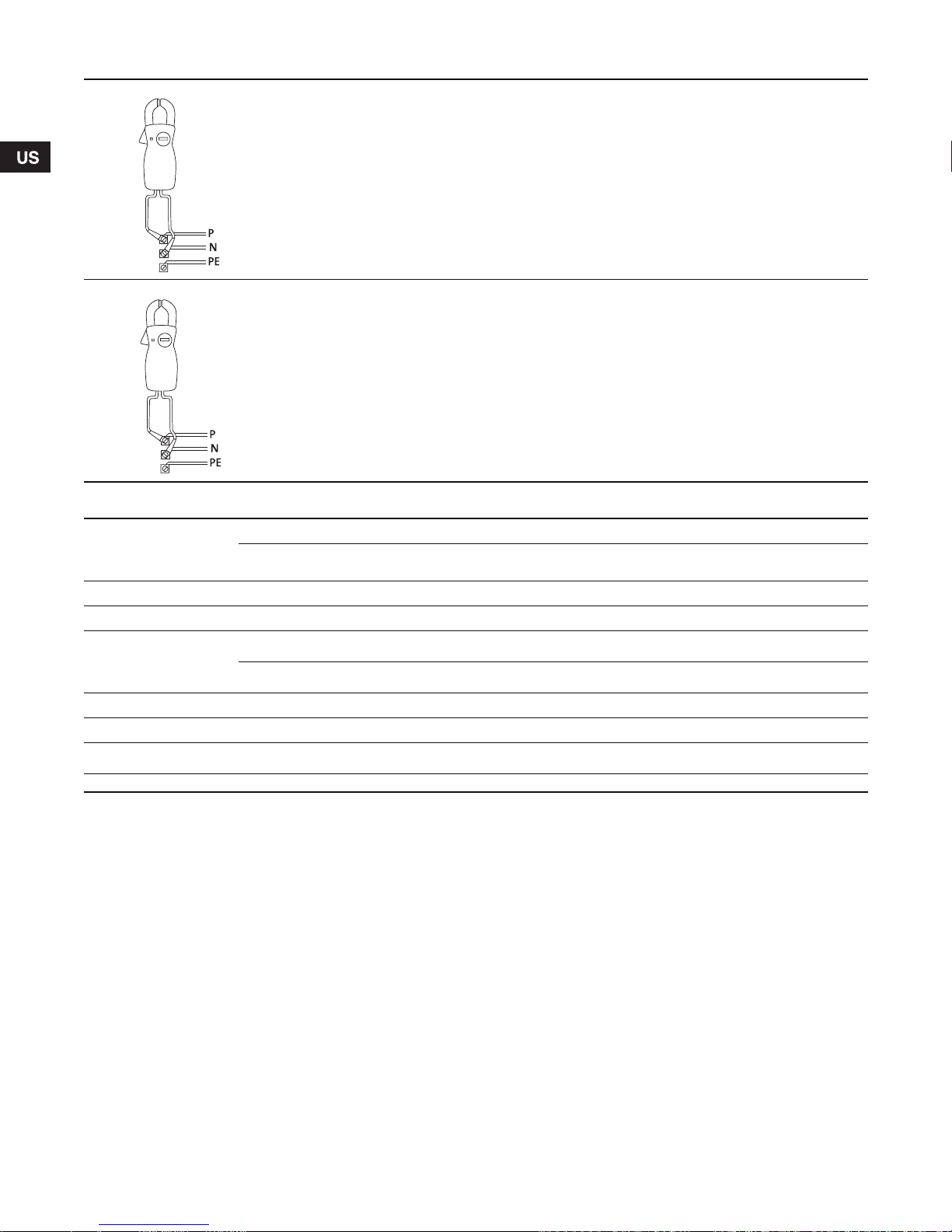
3.3.4 Main power supply, POWER, terminals 1, 2 and PE
(ground)
Connect terminals 1 and 2 to the line and neutral leads of the
main supply. Each terminal can be connected to any of the two
leads.
Circuit breaker: Maximum 16 A.
3.3.5 Motor leads, PUMP, terminals 3, 4 and PE (ground)
IMPORT ANT: The main power supply cables must
not be connected to terminals 3 and 4 (PUMP).
Connect terminals 3 and 4 to the line and neutral leads of the
pump. Each terminal can be connected to any of the two leads.
Connect one PE terminal to the green ground lead from the pump
and one to the ground lead from the main power supply. Each PE
terminal must be connected to its own ground lead.
Maximum wire size of the cables to be connected to BMQE
controller is 10 AWG.
TM04 9412 4110
Fig. 5 Connection for pressure sensor
3.5 Installation of diaphragm pressure tank
The BMQE controller is designed to work with a 2 gallon
diaphragm tank. (For diaphragm tank(s) for two pu mps con nected
in parallel, see section 3.8 BMQE pumps connected in parallel.)
Install a diaphragm tank to insure that the BMQE will shut off at
zero flow. The diaphragm tank must be installed at some point
between the BMQE pump and the pressure sensor.
9
Page 10

3.5.1 Pre-charge pressure setting
Note
The pre-charge pressure of the diaphragm tank must be set to
70 % of the pressure setting in order to use the tank to the limit of
its capacity.
Use the values in the following table. Pre-charge pressure is
measured with 0 psi in the pipeline:
Setting (psi) Pre-charge pressure (psi)
40 28
50 35
60 42
70 49
80 56
90 63
100 70
If the pre-charge pressure is higher than the
pressure setting, the system will have difficulty
controlling the pressure.
If the user wants to adjust the pressure without changing the
pre-charge pressure of the diaphragm tank, the pre-charge
pressure must be equal to the lowest pressure setting used.
Failure to follow this instruction will increase pressure
fluctuations.
3.6 Installation of pressure relief valve
In order to provide protection against the possibility of overpressurization, a pressure relieve valve may be installed
downstream of the BMQE. If a relief valve is installed, it is
recommended that its discharge be plumbed into an appropriate
drainage point.
3.7 Liquid filling and BMQE pump venting
The BMQE is filled with water through the suction port by the
water in the piping system . Follow this pr ocedu re:
1. Install the BMQE pump with the air relief vent in the 12 o’clock
position when installed horizontally; when installed in the
vertical position the air vent must be at the top of the unit.
2. Loosen the air vent screw in the BMQE pump.
3. Fill the BMQE with water until it starts running out of the vent
hole.
4. Tighten the air vent screw.
3.8 BMQE pumps connected in parallel
When connecting BMQE pumps in parallel (fig. 6) a separate
BMQE controller must be used on each BMQE pump.
Set the pressure on one BMQE 10 psi lower than the other.
For BMQE pumps connected in parallel, mounted one above the
other, it is recommended to connect the pipes as shown in fig. 6.
This layout ensures that the BMQE pumps are filled with water
before starting.
TM04 9413 4110
Fig. 6 Booster unit with two BMQE pumps connected in
parallel, mounted one above the other
3.8.1 Additional considerations when connecting in parallel
• All BMQE modules are supplied with a non-return valve.
• BMQE modules connected in parallel may also be installed
vertically.
• As venting problems may arise in such installations, it is
advisable to install suitable air vent devices.
• The BMQE should be positioned with the discharge and air
vent at the top when installed vertically.
• When the maximum flow for BMQE pumps in parallel will
exceed 35 gpm, a 4-gallon or two 2-gallon diaphragm tank(s)
should be used.
4. Operation
4.1 Starting the BMQE pump for the first time
When the BMQE has been connected correctly, it should be
started with the discharge valve closed approximately one-third.
Due to the soft start feature, the pump takes approximately 2
seconds to develop full pressure.
Check that the actual inlet pressure is equal to or greater than the
previously estimated inlet pressure.
When not being used, all modules should be filled with water as
all internal bearings are water lubricated.
If the BMQE is taken out of operation for a long period , the BM QE
should be flushed through with clean water. The modules are
then left with clean water until they are to be used again.
4.2 Generator operation
Power may be supplied to BMQE pumps by an adequately sized
generator. The generator must be sized 50 % above the pumps
P1 (input power) values. Refer to following chart.
10
Motor Hp
0.33 to 0.50 A 1100 1500
0.50 to 0.75 B 1700 2300
1.0 to 1.5 B 2000 3500
Minimum
generator
size
Recommended
generator
output (watts)
Page 11

4.3 BMQE controller operating functions
Green indicator
light
Red indicator
light
Note
BMQE
BMQE
4.3.1 Location of ON / OFF button
The ON / OFF button is located on the front of the BMQE
controller (fig. 7).
4.3.4 Pressure setting
The two arrow buttons on the BMQE controller front are used for
the pressure setting; see fig. 9.
Fig. 7 BMQE controller ON / OFF button
4.3.2 Indicator lights in ON / OFF button
The green and red indicator lights in the ON /OFF button indicate
pump operating condition as follows:
Indication Description
Green indicator light permanently
ON
Green indicator light OFF The system is not operational
Red indicator light permanently ON
The system is operational
Pump has been stopped by means
of the ON / OFF button*
*If the ON/OFF button has been used to stop the pump, this
button must also be used for restarting.
Any alarm indication can be reset by pressing the ON/OFF
button.
If the ON/OFF button is pressed for more than 5 seconds, the
pump is started, irrespective of any active fault/alarm indications
and sensor signals.
When the ON/OFF button is released, the pump will stop, if the
alarm still exists.
Warnin g
Setting the ON/OFF button to the OFF position
DOES NOT remove power from the pump. Before
servicing the pump, remove power at the service
breaker.
TM04 9414 4110
Fig. 9 Pressure setting
Indication of pressure setting
The system pressure set is indicated by a yellow indicator light,
which is permanently on. Setting range: 40-100 psi.
Arrow-up button
When this button is pressed, the system pressure setting is
increased in steps of 10 psi.
Arrow-down button:
When this button is pressed, the system pressure setting is
decreased in steps of 10 psi.
4.3.5 Button locking
The buttons on the BMQE controller can be locked/unlocked by
pressing the two arrow buttons simultaneously for 5 seconds.
When the arrow buttons are used for locking,
take care not to inadvertently change the
pressure setting. When the buttons are locked,
the indicator light is permanently on. See fig. 10.
You can use the following procedure:
1. Set the pressure one step up.
2. Press the arrow-down button as the first one when pressing
the two buttons.
TM04 9417 4110
4.3.3 Indication of pump operation
On the graphical illustration on the BMQE controller face, the p ipe
shows run lights when the pump is operating. When the pump is
not operating, none of the flow indicator lights are on. See fig. 8.
Fig. 8 Location of flow indicator lights on controller
TM04 9418 4110
Fig. 10 Location of lock/unlock button on controller
4.3.6 Alarm functions
The BMQE controller continuously receives operating data from
the pump. The alarm functions indicated on the BMQE controller
front are described in the following sections.
TM04 9416 4110
11
Page 12

4.3.7 Service alarm
BMQE
If one or more factory-set alarm values are exceeded, the
indicator light for service alarm is permanently on. See fig. 11.
Possible service alarms:
• sensor defective
• overload
• over temperature
• speed reduction
• voltage alarm
• no contact to pump.
4.5.1 Dry-run indicator light ON
When the motor is stopped, the dry-running indicator light is
permanently ON. See fig. 12.
TM04 9420 4110
Fig. 12 Location of dry-run indicator light on controller
Fig. 11 Location of service alarm indicator light on controller
The possible alarms and how to identify them and make the
relevant corrections are described in section 6. Maintenance and
service and section 8. Troubleshooting.
4.4 Built-in protections
The motor is protected against the following conditions:
• dry running
• voltage surges (up to 4000 V)
• under voltage
• over voltage
• overload
• over temperature.
The BMQE incorporates an electronic unit which protects the
motor in various situations.
• In case of overload, the built-in overload protection will stop
the BMQE for 5 minutes. After that period, the booster module
will attempt to restart.
• If started without water (dry running), the BMQE will stop after
30 seconds.
• If the BMQE is stopped as a result of dry running, it will restart
automatically after 5 minutes; see section 4.5 Built-in dry-
running protection.
4.5 Built-in dry-running protection
The purpose of the BMQE’s dry-running protection is to protect
the pump in case of insufficient water flow.
The dry-running protection makes the conventional dry-running
protection unnecessary.
No additional cables to the motor are required. The dry run
settings shown in section 8.5 Factory settings are built into the
pump and automatically transmitted to the BMQE controller.
When air enters the pump together with water, the pump power
decreases, and pressure drops, causing the motor to increase
speed. If the power consumption falls below the dry run setting
for an accumulated time of 5 seconds, and the motor speed is
within 1000 rpm of the max speed the BMQE controller stops the
pump and declares a dry run alarm.
TM04 9419 4110
Condition Possible cause Possible remedy
Motor stopped;
dry-run indicator light
permanently ON
Pump performance is
too high compared to
the inlet yield.
In line filter or BMQE
screen is blocked.
Replace pump with a
smaller one.
Filter or BMQE service
is required.
Restarting after dry-run alarm
After 5 minutes (factory setting), the motor will restart
automatically.
4.5.2 Restarting the BMQE pump
To reset the BMQE, switch off the electricity supply for 1 minute.
12
Page 13

5. Position of LED’s
1
2
3
4
5
TM01 8537 1904
Fig. 13 LED’s located on the supply board inside the controller
Pos. Indication Description
1 + 24 V overload Permanent red light when the internal 24 VDC supply is overloaded
+ 24 V
2
3 + 10 V Permanent green light when the internal 10 VDC supply is OK
+ 5 V
4
5 Indicator lights (nine). See fig. 14.
• Control indicator Flashing green light when the pump control is working correctly
• Min. speed Permanent yellow light when the pump is running at minimum speed (3,000 rpm)
• Max. speed Permanent yellow light when the pump is running at maximum speed (10,700 rpm)
• Sensor defective Permanent red light when the sensor signal is out of signal range
• Overload* Permanent red light when the motor load exceeds the stop limit; see section 8.5 Factory settings
• Over temperature* Permanent red light when the motor temperature exceeds the stop limit; see section 8.5 Factory settings
• Speed reduction* Permanent red light when the pump speed is reduced, see section 8.5 Factory settings
• Voltage alarm* Permanent red light when the supply voltage is out of range; see section 8.5 Factory settings
• No contact to pump* Permanent red light when communication between the BMQE controller and the pump is impossible
* Press the ON / OFF button to reset the alarm indication.
Permanent green light when the internal 24 VDC supply is OK
Permanent green light when the internal 5 VDC supply is OK
13
Page 14

6. Maintenance and service
Note
CONTROL INDICATOR
MIN. SPEED
MAX. SPEED
SENSOR DEFECTIVE
OVERLOAD
OVERTEMPERATURES
SPEED REDUCTION
VOLTAGE HARM
NO CONTACT TO PUMP
If a pump has been used for a liquid which is
toxic or injurious to health, the pump will be
classified as contaminated.
If Grundfos is requested to service the pump, Grundfos must be
contacted with details about the pumped liquid, etc. before the
pump is returned for service. Otherwise Grundfos can refuse to
accept the pump for service.
Possible costs of returning the pump are to be paid by the
customer.
However, any application for service (no matter to whom it may
be made) must include details about the pumped liquid if the
pump has been used for liquids which are toxic or injurious to
health.
For the replacement and repair of parts of the BMQE, please
refer to:
• Service instructions for SQE pumps describing replacement of
motor cable and motor.
• Parts list for SQE with instructions for dismantling and
assembly of pump and motor.
Grundfos Service instructions and parts lists can be found at
www.grundfos.com (WebCAPS) or WinCAPS.
6.1 Storage
• BMQE pump storage temperature:
+ 32 to + 140 °F (0° to + 60 °C).
• BMQE controller storage temperature:
- 22 to + 140 °F (- 30 to + 60 °C).
6.2 Frost protection
If the BMQE has to be stored after use, it must be stored in a
frost-free location or it must be ensured that the motor liquid is
frost-proof. The BMQE is shipped from the factory with motor fluid
that protects the motor down to - 4 °F (- 20 °C).
The motor must not be stored without being filled with motor
liquid.
6.3 BMQE controller service
.
The BMQE controller continuously receives operating data from
the pump. In case of an alarm, the service indicator light is
permanently on. See fig. 11.
The service indicator light will be permanently on if one of the
following alarm situations occurs:
• sensor defective
•overload
• over temperature
• speed reduction
• voltage alarm
• no contact to pump.
To identify the cause of the service alarm, it is necessary to
remove the front cover from the BMQE controller. Fit the front
cover as shown (fig. 14) to avoid disconnecting the multi-core
cable.
14
Warnin g
Before starting any work on the BMQE controller,
make sure that the electricity supply has been
switched OFF and that it cannot be accidentally
switched on.
TM01 8435 4110
Fig. 14 LED’s and the alarm texts on the supply board inside
the controller
A number of LED’s are mounted on the supply board inside the
BMQE controller; see section 5. Position of LED’s.
Figure 14 shows the LED’s and the alarm texts on the supply
board.
6.4 Optional R100 interface
The R100 remote control can be used as a supplement for the
installer and as an excellent troubleshooting tool. Grundfos highly
recommends the use of the R100 for diagnosing problems and
accessing system information unavailable through other means.
The R100 provides wireless communication with the controller.
Note: It is not necessary to use the R100 to operate the system.
The R100 offers additional features.
The R100 communicates via infrared light. During
communication, there must be visual contact between the
controller and the R100.
The best visual contact between the two units is obtained by
pointing the R100 at the lower arrow button or by removing the
front cover and pointing the R100 at the right side of the
controller.
The R100 offers possibilities of altering factory settings and
reviewing operating status of the pump.
When the communication between the R100 and controller has
been established, the red indicator light in the On/Off button will
flash.
For general use of the R100, see the operating instructions
included with the R100.
Page 15

7. Technical data
7.1 Technical data for BMQE pump
Technical data - BMQE pump
Main power supply to pump
Starting
Stopping Soft stopping when stopped by the BMQE controller
Run-up time
Motor protection
Sound pressure level
Reset function BMQE pumps can be reset via BMQE controller
Power factor PF = 1.
Operation via generator
Pipe connection 1.25” NPT inlet / 1” NPT discharge
Strainer Holes of the strainer: ø0.09” (2.3 mm)
Approvals UL Listed, CE (SQE Pump with MSE 3 motor only)
Weight 31 lbs. (14.1 kg)
Voltage 1 x 100-240 V –10 % / +6 %, 60 Hz
1 x 200-240 V –10 % / +6 %, 60 Hz
1 x 110-115 V –10 % / +6 %, 60 Hz
Soft starting.
The motor starting current is equal to the highest value stated on the BMQE nameplate.
Maximum: 2 seconds.
No limitation to the number of starts/stops per hour.
Built into the pump. Protection against:
• Dry run ning
• Over voltage and under voltage
230 V cuts out at < 150 V and > 280 V
115 V cuts out at < 75 V and > 150 V
•Overload
• Over temperature
The sound pressure level is < 74 db[A] at a distance of 3 feet (1 meter).
It is recommended by Grundfos that the pump be installed with sound and vibration dampening equipment
such as flexible piping adapters and anti-vibration mounting.
The pump should not be mounted in or adjacent to living quarters.
The pump can also be wrapped with sound proofing insulation to reduce noise.
It is recommended that the generator output is equal to the motor input power P1 [kW]
plus 50 %; min. P1 +10 %, however.
7.2 Technical data for BMQE controller
Technical data - BMQE controller
Power consumption 5 W
Current consumption Maximum 130 mA
Motor cable
Enclosure class NEMA 3R (IP 55)
Ambient temperature In operation: -22 to +122 °F (-30 to +50 °C). During storage: -22 to +140 °F (-30 to +60 °C)
Relative air humidity 95 %
Pump cable Maximum length between BMQE controller and pump: 650 ft (198 m)
Back-up fuse Maximum: 16 A
Load Max. 100 mA
Approvals UL Listed, CE
• 2-wire w /ground, 12 AWG Teflon
• B: Black (Line, Neutral)
• G: Green (Ground)
15
Page 16

8. Troubleshooting
8.1 Fault finding chart - BMQE pump
Also refer to section 8.2 Fault finding chart - BMQE controller to troubleshoot the controller.
Fault Possible cause Possible remedy
1. The BMQE does not run. a) The GFI or the voltage-operated GFI has
2. The BMQE runs but gives no water. a) The discharge valve is closed. Open the valve.
3. The BMQE runs at reduced capacity. a) The valves in the discharge pipe are partly
4. Frequent starts and stops. a) The supply voltage is unstable. C heck t he electricity supply.
tripped out.
b) No electricity supply. Contact the electricity supply company.
c) The motor protection has cut off the electricity
supply due to overload.
d) The pump/cable is defective. Repair/replace the pump/cable.
e) Over voltage has occurred. Check the electricity supply.
b) The suction strainer is choked up. Pull the pump out of the sleeve and clean the
c) The pump is defective. Pull the pump out of the sleeve and repair/replace
closed/blocked.
b) The discharge pipe is partly choked by
impurities.
c) The pump is partly choked by impurities. Pull the pump out of the sleeve. Check and clean
d) The pump is defective. Pull the pump out of the sleeve and repair/replace
e) Leakage in the pipe work. Check and repair the pipe work.
f) Under voltage has occurred. Check the electricity supply.
b) The motor temperature becomes too high. Check the water temperature.
Cut in the circuit breaker.
Check whether the motor/pump is blocked.
strainer.
the pump.
Check and clean/replace the valves, if necessary.
Clean/replace the discharge pipe.
or replace the pump, if necessary. Clean the
pipes.
the pump.
16
Page 17

8.2 Fault finding chart - BMQE controller
Also refer to 8.1 Fault finding chart - BMQE pump to troubleshoot the pump.
Fault Possible cause Possible remedy
1. No light in the front cover. a) The ribbon cable connection is loose or
2. The pump does not start. The green indicator
light in the ON/OFF button
is on. No alarm is indicated.
3. The pressure is not constant. a) The pump is not of the correct type or the pre-
4. The pump runs continuously. a) The pump cannot deliver the set pressure.
defective.
a) The BMQE controller, the pressure sensor or
the pump is defective.
charge pressure of the diaphragm tank is
incorrect.
b) No contact between BMQE pump and
controller.
The controller or the sensor
is defective.
Is the control indicator LED flashing?
If not, the BMQE controller is
defective.
Check that the ribbon cable connection
is secure.
Check that the control indicator LED is flashing.
If not, the BMQE controller is defective.
Check that the system pressure is 7 psi below the
pressure setting.
If so, the pump is supposed to start.
Open a tap to be sure.
If the pump starts, the system is probably working
properly. The system pressure can be read on the
pressure gauge.
Refer to fault 13 to troubleshoot the pressure
sensor. If the pump has not started yet, proceed
as follows:
Press the ON/OFF button for 5 seconds. If the
pump starts, the controller or the sensor may be
defective.
Note: The pressure is not controlled and may rise
to a high level.
Check that the LED for Max. speed or Min. speed
is on. If so, this indicates that the pump has
reached a limit. See section 3.4 Installation of
pressure sensor. Replace the pump, if necessary.
Check the pre-charge pressure of the diaphragm
tank.
Note: Remember to stop and drain the system
pressure before the pressure is checked.
Make sure the diaphragm tank is the
recommended 2 gal. size.
Check whether the sensor is positioned far away
from the tap
If so, the pressure variations may be caused by
friction losses, see section 3.4.1 Positioning the
pressure sensor.
Check that the LED for “No contact to pump” is on.
If so, go to fault no. 14.
Try to lower the pressure setting; see section
7.2.3. Note that the pump may run for about 15 to
20 seconds before it stops.
Check to see that the control indicator LED is
flashing.
Check to see whether the pipe end of the sensor is
blocked. If so, remove the blockage.
Try to stop the pump by means of the
ON/OFF button. If this is not possible, the
controller is defective. Replace the controller.
Refer to Fault 13 to troubleshoot the pressure
sensor.
17
Page 18

Fault Possible cause Possible remedy
5. The BMQE controller indicates
“No contact to pump”.
6. Even AFTER re place ment, the BMQE
controller indicates “No contact to pump”.
7. The BMQE controller indicates “Over voltage”
or “Under voltage”.
8. The controller indicates “Dry running”.
Note: If the power consumption is lower than
the dry-running stop setting and the motor
speed is within 1000 rpm of programmed
maximum speed, for an accumulated period
of 5 seconds, the pump will be stopped.
9. The controller indicates “Speed reduction”
and “Under voltage”.
Note: Speed reduction is activated so as to
maintain a reduced performance. When the
supply voltage falls so low that it can no
longer supply the necessary current to
maintain 3,000 rpm, the pump will be stopped.
a) The pump cable is longer than 650 feet. Reduce the length of the pump cable.
b) Cable breakage Switch off the main power supply to
c) Cross communication with adjacent BMQE
controller.
d) The BMQE controller communication part is
defective.
e) The BMQE motor communication
part is defective.
a) Numbering of BMQE pump and BMQE
controller is different.
a) The supply voltage is unstable or outside the
voltage range specified for the installed motor
type.
a) The pump performance is too high for
b) The well screen is blocked. Check the well capacity and restore
a) The supply voltage is unstable or lower than
the voltage range specified for the installed
motor type.
b) The pump is not of the correct type. Install correct pump type.
c) The voltage drop in the pump cable is too
great.
the inlet yield.
the controller. Switch on the main power supply
again. The pump is now connected direct to the
main power supply without interference from the
controller.
Perform these two checks:
Does the motor start?
If so, the cable is OK. Go to 5d).
If not, switch off the mains supply again.
Remove cable and cable plug from the motor and
ohm out cable including plug.
Is the cable OK?
If so, the motor is defective. Replace the motor.
If not, replace the cable.
If another BMQE controller is installed:
If pump cables run parallel to each other,
physically separate them by 12 - 14 inches (305355 mm) or rewire using shielded cable.
Are the three controller supply board LED’s in pos.
2, 3 and 4 on, and is the control indicator LED
flashing? (See section 5. Position of LED’s.)
If so, the mains supply is OK. Is the LED “No
contact to pump” of the new controller also on?
If so, the controller is OK. Go to 5e).
If not, the controller which was removed is
defective.
As a result of the above mentioned
troubleshooting checks, replace the BMQEmotor.
If an BMQE controller system
has been given a number, this number
is stored in both the pump and
controller.
A new controller or pump may not have a number
corresponding to the number stored in the
previous unit. Therefore, “No contact to pump” is
indicated even if there is no fault.
Give the new system the number used
in the previous unit in order to obtain
correspondence between the numbering of the pump and the controller. This requires
an R100.
Note: Two systems on the same main
power supply must not have the same
number!
Check — possibly over a period of time — that the
supply voltage is according to the values in
section 2. Operating conditions.
Note: As the voltage is detected at
the motor, allow for the voltage drop in
the pump cable.
Replace the pump with a smaller
pump or reduce the pump performance,
by lowering maximum speed, or
reducing set pressure.
water supply to the well.
Restore correct supply voltage.
Replace the pump cable with lower
gauge wires or reduce cable length.
10. The controller indicates“Speed reduction” and
“Overload”.
Speed reduction is activated so as to maintain
a reduced performance.
11. The controller indicates “Over temperature”
(the temperature sensor in the motor is
sensing a temperature above the values
stated in Section 9, Factory settings).
18
a) The pump is worn or blocked. The pump must be serviced.
b) The pump is too large for the installedmotor. Replace pump or motor.
Insufficient cooling of the motor. Restore correct cooling of the motor.
a)
The flow velocity past the motor should
be at least 0.5 ft/s (0.15 m/s).
Page 19

Fault Possible cause Possible remedy
Note
12. The controller indicates “Overlo ad”. a) The pump is worn or blocked. The pump must be serviced.
b) The pump is too large for the installed motor. Replace pump or motor.
13. The controller indicates “Sensor defective”. a) The pressure sensor is defective. Check that the sensor is wired correctly.
14. The pump is operating on/off. a) No communication. Check that the LED “No contact to
If the sensor type is 4-20 mA, measure
the DC voltage across the sensor input
terminals. If the DC voltage measured
at the sensor input terminals is not
between 2 and 10 volts the sensor,
or wiring is defective. Refer to section
8.6 Pressure sensor voltage chart.
Replace defective parts. Are the LED
“Sensor defective” and the LED, pos. 1,
on? See section 5. Position of LED’s.
If so, the total load of 24 VDC from
terminal 5 is above 100 mA. Disconnect
the sensor in order to determine if it is
defective. Replace defective sensor.
If not, the load is OK, but the BMQE
controller sensor input may be
defective.
pump” is on.
If so, the controller starts and stops the pump,
based on the sensor signal only. The controller
has to be reset after each 250 stops. See fault 5)
for remedy.
8.3 Instruments not allowed
Note: The use of the following instruments is not allowed during
fault finding:
When measuring, use RMS instruments.
TM04 9421 4110
19
Page 20
8.4 Checking of motor and cable
1. Supply voltage a) Measure the voltage (RMS) between line and neutral.
Connect the voltmeter to the terminals at the connection.
When the motor is loaded, the voltage should be within
the range specified in section For general use of the
R100, see the operating instructions included with the
R100.
Large variations in supply voltage indicate poor
electricity supply, and the BMQE should be stopped
until the defect has been remedied.
2. Current consumption a) Measure the current (RMS) while the pump is operating at
a constant discharge head (if possible, at the capacity
where the motor is most heavily loaded).
For maximum current, see nameplate.
If the current exceeds the full load current, there are
the following possible faults:
• Poor connection in leads, possibly in the cable joint.
• Too low supply voltage, see item 1).
8.5 Factory settings
200-240 V motors 100-115 V motors
Alarm
Sensor defective 4-20 mA (the value is stored in the BMQE controller)
Overload 5.2 A 8.4 A 12.0 A 12.0 A
Over temperature
Speed reduction In connection with under voltage or overload
Over voltage* 315 VAC 315 VAC 315 VAC 180 VAC
Under voltage
Dry-running 300 W 680 W 800 W 300 W
* 200-240 V motors: Operation is guaranteed up to 280 VAC.
100-115 V motors: Operation is guaranteed up to 150 VAC.
In order to avoid unnecessary stops, the over voltage stop limit is as stated.
SQ/SQE/SQE-NE 03A and
05A models
Stop limit:
163 °F (73 °C)
Restart:
145 °F (63 °C)
Speed reduction: 198 V
Stop limit: 150 V
SQ/SQE/SQE-NE05B and
07B models
Stop limit:
162 °F (72 °C)
Restart:
144 °F (62 °C)
Speed reduction: 198 V
Stop limit: 150 V
SQ/SQE/SQE-NE1.0C and
1.5C models
Stop limit:
203 °F (95 °C)
Restart:
185 °F (85 °C)
Speed reduction: 198 V
Stop limit: 150 V
All models
Stop limit:
185 °F (85 °C)
Restart:
167 °F (75 °C)
Speed reduction: 90 V
Stop limit: 75 V
20
Subject to altera tion s.
Page 21

8.6 Pressure sensor voltage chart
Voltage to pressure chart for BMQE pressure sensors. Measure DC voltage between Sensor IN and Sensor Ground. Voltages less than 2
or greater than 10 indicate an incorrectly wired or a faulty sensor.
DC voltage psi DC voltage psi DC voltage psi
1.9 0.0 4.5 40.5 7.1 81.0
2.0 0.7 4.6 41.2 7.2 81.7
2.0 1.5 4.6 42.0 7.2 82.5
2.1 2.2 4.7 42.7 7.2 83.2
2.1 3.0 4.7 43.5 7.3 84.0
2.2 3.7 4.8 44.2 7.3 84.7
2.2 4.5 4.8 45.0 7.4 85.5
2.3 5.2 4.8 45.7 7.4 86.2
2.3 6.0 4.9 46.5 7.5 87.0
2.4 6.7 4.9 47.2 7.5 87.7
2.4 7.5 5.0 48.0 7.6 88.5
2.4 8.2 5.0 48.7 7.6 89.2
2.5 9.0 5.1 49.5 7.7 90.0
2.5 9.7 5.1 50.2 7.7 90.7
2.6 10.5 5.2 51.0 7.8 91.5
2.6 11.3 5.2 51.7 7.8 92.2
2.7 12.0 5.3 52.5 7.9 93.0
2.7 12.8 5.3 53.2 7.9 93.7
2.8 13.5 5.4 54.0 8.0 94.5
2.8 14.3 5.4 54.7 8.0 95.2
2.9 15.0 5.5 55.5 8.1 96.0
2.9 15.7 5.5 56.2 8.1 96.7
3.0 16.5 5.6 57.0 8.2 97.5
3.0 17.2 5.6 57.7 8.2 98.2
3.1 18.0 5.7 58.5 8.3 99.0
3.1 18.7 5.7 59.2 8.3 99.7
3.2 19.5 5.8 60.0 8.4 100.5
3.2 20.2 5.8 60.7 8.4 101.3
3.3 21.0 5.9 61.5 8.4 102.0
3.3 21.7 5.9 62.2 8.5 102.8
3.4 22.5 6.0 63.0 8.5 103.5
3.4 23.2 6.0 63.7 8.6 104.3
3.5 24.0 6.0 64.5 8.6 105.0
3.5 24.7 6.1 65.2 8.7 105.8
3.6 25.5 6.1 66.0 8.7 106.5
3.6 26.2 6.2 66.7 8.8 107.3
3.6 27.0 6.2 67.5 8.8 108.0
3.7 27.7 6.3 68.2 8.9 108.8
3.7 28.5 6.3 69.0 8.9 109.5
3.8 29.2 6.4 69.7 9.0 110.3
3.8 30.0 6.4 70.5 9.0 111.0
3.9 30.7 6.5 71.2 9.1 111.8
3.9 31.5 6.5 72.0 9.1 112.5
4.0 32.2 6.6 72.7 9.2 113.3
4.0 33.0 6.6 73.5 9.2 114.0
4.1 33.7 6.7 74.2 9.3 114.8
4.1 34.5 6.7 75.0 9.3 115.5
4.2 35.2 6.8 75.7 9.4 116.3
4.2 36.0 6.8 76.5 9.4 117.0
4.3 36.7 6.9 77.2 9.5 117.8
4.3 37.5 6.9 78.0 9.5 118.5
4.4 38.2 7.0 78.7 9.6 119.3
4.4 39.0 7.0 79.5 9.6 120.0
4.5 39.7 7.1 80.2
21
Page 22

9. Disposal
This product or parts of it must be disposed of in an
environmentally sound way. Use the public or private waste
collection service. If this is not possible, dispose of the product
according to local regulations. Grundfos recommends that the
products are recycled whenever possible.
22
Page 23

U.S.A.
GRUNDFOS Pumps Corporation
17100 West 118th Terrace
Olathe, Kansas 66061
Phone: +1-913-227-3400
Telefax: +1-913-227-3500
Canada
GRUNDFOS Canada Inc.
2941 Brighton Road
Oakville, Ontario
L6H 6C9
Phone: +1-905 829 9533
Telefax: +1-905 829 9512
México
Bombas GRUNDFOS de México S.A. de C.V.
Boulevard TLC No. 15
Parque Industrial Stiva
Aeropuerto
Apodaca, N.L.C.P. 66600
Phone: +52-81-8144 4000
Telefax: +52-81-8144 4010
Addresses revised 22.09.2005
Page 24

Being responsible is our foundation
Thinking ahead makes it possible
Innovation is the essence
L-BMQ-TL-01 1010
Repl. L-EZ-TL-001 0308
© 2008, 2010 Grundfos Pumps Corp.
www.grundfos.com
US
The name Grundfos, the Grundfos logo, and the payoff Be–Think–Innovate are registrated trademarks
owned by Grundfos Management A/S or Grundfos A/S, Denmark. All rights reserved worldwide.
 Loading...