

Grundfos LME Series, LMDE Series, LPE Series, LPDE Series, TPE Series Installation And Operating Instructions Manual
...Page 1

LM(D)E, LP(D)E, TPE(D), NKE,
GRUNDFOS INSTRUCTIONS
NBE, CLME, 1~ and
Installation and operating instructions
Montage- und Betriebsanleitung
Notice d’installation et d’entretien
Istruzioni di installazione e funzionamento
Instrucciones de instalación y funcionamiento
Instruções de instalação e funcionamento
√‰ЛБ›В˜ ВБО·Щ¿ЫЩ·ЫЛ˜ О·И ПВИЩФ˘ÚÁ›·˜
Installatie- en bedieningsinstructies
Monterings- och driftsinstruktion
Asennus- ja käyttöohjeet
Monterings- og driftsinstruktion
3
~
Page 2

Declaration of Conformity
We GRUNDFOS declare under our sole responsibility that the products
LM(D)E, LP(D)E, TPE(D), NKE, NBE and CLME, to which this declaration
relates, are in conformity with the Council Directives on the approximation
of the laws of the EEC Member States relating to:
– Machinery (98/37/EEC).
Standard used: EN 292.
– Electromagnetic compatibility (89/336/EEC).
Standard used: EN 61 800-3.
– Electrical equipment designed for use within certain voltage limits
(73/23/EEC).
Standards used: EN 60 335-1 and EN 60 335-2-51.
Konformitätserklärung
Wir GRUNDFOS erklären in alleiniger Verantwortung, daß die Produkte
LM(D)E, LP(D)E, TPE(D), NKE, NBE und CLME, auf die sich diese Er-
klärung bezieht, mit den folgenden Richtlinien des Rates zur Angleichung
der Rechtsvorschriften der EG-Mitgliedstaaten übereinstimmen:
– Maschinen (98/37/EWG).
Norm, die verwendet wurde: EN 292.
– Elektromagnetische Verträglichkeit (89/336/EWG).
Norm, die verwendet wurde: EN 61 800-3.
– Elektrische Betriebsmittel zur Verwendung innerhalb bestimmter
Spannungsgrenzen (73/23/EWG).
Normen, die verwendet wurden: EN 60 335-1 und EN 60 335-2-51.
Déclaration de Conformité
Nous GRUNDFOS déclarons sous notre seule responsabilité que les produits LM(D)E, LP(D)E, TPE(D), NKE, NBE et CLME auxquels se réfère
cette déclaration sont conformes aux Directives du Conseil concernant le
rapprochement des législations des Etats membres CEE relatives à
– Machines (98/37/CEE).
Standard utilisé: EN 292.
– Compatibilité électromagnétique (89/336/CEE).
Standard utilisé: EN 61 800-3.
– Matériel électrique destiné à employer dans certaines limites de ten-
sion (73/23/CEE).
Standards utilisés: EN 60 335-1 et EN 60 335-2-51.
Declaración de Conformidad
Nosotros GRUNDFOS declaramos bajo nuestra única responsabilidad
que los productos LM(D)E, LP(D)E, TPE(D), NKE, NBE y CLME a los
cuales se refiere esta declaración son conformes con las Directivas del
Consejo relativas a la aproximación de las legislaciones de los Estados
Miembros de la CEE sobre
– Máquinas (98/37/CEE).
Norma aplicada: EN 292.
– Compatibilidad electromagnética (89/336/CEE).
Norma aplicada: EN 61 800-3.
– Material eléctrico destinado a utilizarse con determinados límites de
tensión (73/23/CEE).
Normas aplicadas: EN 60 335-1 y EN 60 335-2-51.
¢‹ÏˆÛË ™˘ÌÌfiÚʈÛ˘
∂Ì›˜ Ë GRUNDFOS ‰ЛПТУФ˘МВ МВ ·рФОПВИЫЩИО¿ ‰ИО‹ М·˜ В˘ı‡ÓË fiÙÈ
Ù· ðÚÔÈfiÓÙ· LM(D)E, LP(D)E, TPE(D), NKE, NBE Î·È CLME Û˘Ì-
МФЪКТУФУЩ·И МВ ЩЛУ √‰ËÁ›· ÙÔ˘ ™˘Ì‚Ô˘Ï›Ô˘ Вр› ЩЛ˜ Ы‡БОПИЫЛ˜ ЩˆУ
УfiÌˆÓ ÙˆÓ ∫Ú·ÙÒÓ MÂÏÒÓ Ù˘ ∂˘Úˆð·È΋˜ ∂ÓˆÛ˘ Û ۯ¤ÛË Ì ٷ:
– ªË¯·Ó‹Ì·Ù· (98/37/EEC).
¶ÚfiÙ˘ðÔ ðÔ˘ ¯ЪЛЫИМФрФИ‹ıËÎÂ: EN 292.
– ∏ПВОЩЪФМ·БУЛЩИО‹ Ы˘Ì‚·ÙfiÙËÙ· (89/336/EEC).
¶ÚfiÙ˘ðÔ ðÔ˘ ¯ЪЛЫИМФрФИ‹ıËÎÂ: EN 61 800-3.
– ∏ПВОЩЪИО¤˜ Ы˘Û΢¤˜ ۯ‰ȷṲ̂Ó˜ ÁÈ¿ ¯Ú‹ÛË ÂÓÙfi˜ ФЪИЫМ¤УˆУ
ФЪ›ˆУ ЛПВОЩЪИО‹˜ Щ¿ЫЛ˜ (73/23/EEC).
¶ЪfiÙ˘ð· ðÔ˘ ¯ЪЛЫИМФрФИ‹ıËηÓ: EN 60 335-1 Î·È EN 60 335-2-51.
Dichiarazione di Conformità
Noi GRUNDFOS dichiariamo sotto la nostra esclusiva responsabilità che
i prodotti LM(D)E, LP(D)E, TPE(D), NKE, NBE e CLME, ai quali questa
dichiarazione si riferisce, sono conformi alle direttive del Consiglio, concernenti il ravvicinamento delle legislazioni degli Stati membri CEE relativi
a
– Macchine (98/37/CEE).
Standard usato: EN 292.
– Compatibilità elettromagnetica (89/336/CEE).
Standard usato: EN 61 800-3.
– Materiale elettrico destinato ad essere utilizzato entro certi limiti di
tensione (73/23/CEE).
Standard usati: EN 60 335-1 e EN 60 335-2-51.
Declaração de conformidade
Nós GRUNDFOS declaramos sob nossa responsabilidade que os produtos LM(D)E, LP(D)E, TPE(D), NKE, NBE e CLME, aos quais esta declaração se refere, estão em conformidade com as Directivas Comunitárias
com aproximação das leis dos estados membros da CEE para:
– Máquinas (98/37/CEE).
Norma usada: EN 292.
– Compatibilidades Electromagnéticas (89/336/CEE).
Norma usada: EN 61 800-3.
– Equipamento Eléctrico desenhado para uso de certos limites de tensão
(73/23/CEE).
Norma usada: EN 60 335-1 e EN 60 335-2-51.
Overeenkomstigheidsverklaring
Wij GRUNDFOS verklaren geheel onder eigen verantwoordelijkheid dat
de produkten LM(D)E, LP(D)E, TPE(D), NKE, NBE en CLME waarop
deze verklaring betrekking heeft in overeenstemming zijn met de Richtlijnen van de Raad inzake de onderlinge aanpassing van de wetge vingen
van de Lid-Staten betreffende
– Machines (98/37/EEG).
Norm: EN 292.
– Elektromagnetische compatibiliteit (89/336/EEG).
Norm: EN 61 800-3.
– Elektrisch materiaal bestemd voor gebruik binnen bepaalde spannings-
grenzen (73/23/EEG).
Normen: EN 60 335-1 en EN 60 335-2-51.
Försäkran om överensstämmelse
Vi GRUNDFOS försäkrar under ansvar, att produkterna LM(D)E, LP(D)E,
TPE(D), NKE, NBE och CLME, som omfattas av denna försäkran, är i
överensstämmelse med Rådets Direktiv om inbördes närmande till EUmedlemsstaternas lagstiftning, avseende
– Maskinell utrustning (98/37/EC).
Använd standard: EN 292.
– Elektromagnetisk kompatibilitet (89/336/EC).
Använd standard: EN 61 800-3.
– Elektrisk material avsedd för användning inom vissa spänningsgränser
(73/23/EC).
Använda standarder: EN 60 335-1 och EN 60 335-2-51.
Overensstemmelseserklæring
Vi GRUNDFOS erklærer under ansvar, at produkterne LM(D)E, LP(D)E,
TPE(D), NKE, NBE og CLME, som denne erklæring omhandler, er i over-
ensstemmelse med Rådets direktiver om indbyrdes tilnærmelse til EF
medlemsstaternes lovgivning om:
– Maskiner (98/37/EEC).
Anvendt standard: EN 292.
– Elektromagnetisk kompatibilitet (89/336/EEC).
Anvendt standard: EN 61 800-3.
– Elektrisk materiel bestemt til anvendelse inden for visse
spændingsgrænser (73/23/EEC).
Anvendte standarder: EN 60 335-1 og EN 60 335-2-51.
2
Vastaavuusvakuutus
Me GRUNDFOS vakuutamme yksin vastuullisesti, että tuotteet LM(D)E,
LP(D)E, TPE(D), NKE, NBE ja CLME, jota tämä vakuutus koskee, nou-
dattavat direktiivejä jotka käsittelevät EY:n jäsen valtioiden koneellisia laitteita koskevien lakien yhdenmukaisuutta seur.:
– Koneet (98/37/EY).
Käytetty standardi: EN 292.
– Elektromagneettinen vastaavuus (89/336/EY).
Käytetty standardi: EN 61 800-3.
– Määrättyjen jänniterajoitusten puitteissa käytettävät sähköiset laitteet
(73/23/EY).
Käytetyt standardit: EN 60 335-1 ja EN 60 335-2-51.
Bjerringbro, 1st January 2002
Jan Strandgaard
Technical Manager
Page 3

LM(D)E, LP(D)E, TPE(D), NKE,
NBE, CLME, 1~ and
Installation and
operating instructions
Montage- und
Betriebsanleitung
Notice d’installation
et d’entretien
Istruzioni di installazione
e funzionamento
3
~
Page 4
Seite 21
Page 39
Pag. 56
Instrucciones de instalación
y funcionamiento
Instruções de instalação
e funcionamento
√‰ЛБ›В˜ ВБО·Щ¿ЫЩ·ЫЛ˜
О·И ПВИЩФ˘ÚÁ›·˜
Installatie- en
bedieningsinstructies
Monterings- och
driftsinstruktion
Pág. 73
Pág. 90
™ÂÏ›‰· 107
Pag. 124
Sida 141
Asennus- ja
käyttöohjeet
Monterings- og
driftsinstruktion
Sivu 158
Side 175
3
Page 4

CONTENTS
Page
1. General 4
1.1 Twin-head pumps 4
2. Installation 4
2.1 Electrical connection – single-phase pumps 5
2.1.1 Mains switch 5
2.1.2 Protection against electric shock – indirect contact 5
2.1.3 Additional protection 5
2.1.4 Motor protection 5
2.1.5 Overvoltage protection 5
2.1.6 Supply voltage 5
2.1.7 Start/stop of pump 5
2.2 Electrical connection – three-phase pumps 6
2.2.1 Mains switch 6
2.2.2 Protection against electric shock – indirect contact 6
2.2.3 Additional protection 6
2.2.4 Motor protection 6
2.2.5 Overvoltage protection 6
2.2.6 Supply voltage 6
2.2.7 Start/stop of pump 6
2.3 Other connections – single-phase pumps 7
2.4 Other connections – single-phase TPED pumps 7
2.5 Other connections – three-phase pumps 8
2.6 Signal cables 8
3. Setting the pump 9
3.1 Control modes 9
3.2 Operating modes 9
3.2.1 Additional operating modes – single-phase TPED
pumps 9
3.3 Factory setting 10
3.4 Factory setting – single-phase TPED pumps 10
4. Setting by means of control panel 10
4.1 Setpoint setting 10
4.2 Setting to max. curve duty 11
4.3 Setting to min. curve duty 11
4.4 Start/stop of pump 11
5. Setting by means of R100 12
5.1 Menu OPERATION 13
5.1.1 Setpoint setting 13
5.1.2 Setting of operating mode 13
5.1.3 Fault indications 13
5.1.4 Alarm log 13
5.2 Menu STATUS 13
5.2.1 Display of actual setpoint 13
5.2.2 Display of operating mode 13
5.2.3 Display of actual value 13
5.2.4 Display of actual speed 14
5.2.5 Display of input power and power consumption 14
5.2.6 Display of operating hours 14
5.3 Menu INSTALLATION 14
5.3.1 Selection of control mode 14
5.3.2 Setting of controller 14
5.3.3 Selection of external setpoint signal 15
5.3.4 Selection of fault, operating or ready signal relay 15
5.3.5 Blocking of the buttons on the pump 15
5.3.6 Allocation of pump number 15
5.3.7 Selection of function for digital input 15
5.3.8 Setting of sensor 15
5.3.9 Setting of min. and max. curves 15
6. External forced-control signals 16
6.1 Start/stop input 16
6.2 Digital input 16
7. External setpoint signal 16
8. Bus signal 16
9. Priority of settings 17
10. Indicator lights and signal relay 18
11. Megging 18
12. Technical data – single-phase pumps 19
12.1 Supply voltage 19
12.2 Leakage current 19
12.3 Inputs/output 19
13. Technical data – three-phase pumps 19
13.1 Supply voltage 19
13.2 Leakage current 19
13.3 Inputs/output 19
13.4 Other technical data 20
14. Disposal 20
Before beginning installation procedures, these installation and operating instructions should be studied carefully. Furthermore, the enclosed installa-
tion and operating instructions for the standard
pump should be studied carefully. The installation
and operation should also be in accordance with local regulations and accepted codes of good practice.
1. General
GRUNDFOS E-pumps are pumps fitted with frequency-controlled
standard motors for single-phase or three-phase mains connection.
The pumps have a built-in PI controller and can be connected to
an external sensor enabling control of for instance pressure, differential pressure, temperature, differential temperature or flow in
the system in which the pumps are installed. The pumps can be
set to uncontrolled operation, i.e. the pump performance can be
set according to the demand.
The pumps are typically used as circulator pumps in large heating
or cooling water systems with variable demands.
The desired value (setpoint), e.g. the desired differential pressure
if a differential pressure sensor has been installed, can be set directly on the pump control panel, via an input for external setpoint
signal or by means of the GRUNDFOS wireless remote control
R100.
All other settings are made by means of the R100.
Important parameters such as actual value of control parameter,
power consumption, etc. can be read via the R100.
The pump incorporates inputs for external potential-free contacts
for start/stop and digital function. The digital function enables external setting of max. curve or min. curve.
The pump incorporates an output for a potential-free fault, operating or ready signal.
Furthermore, the pump has an input for bus communication. Via
the bus communication input, the pump can be controlled and
monitored by a building management system or another external
control system.
1.1 Twin-head pumps
Single-phase twin-head pumps do not require any external controller.
Three-phase twin-head pumps usually require an external controller. The GRUNDFOS Delta Control 2000 ME has been developed for this application.
For further details about the setting and connection of threephase twin-head pumps, see installation and operating instructions for the Delta Control 2000 ME.
2. Installation
To ensure cooling of motor and electronics, the following must be
observed:
• Place the pump in such a way that sufficient cooling is ensured.
• The temperature of the cooling air must not exceed 40°C.
• Motor cooling fins and fan bl ades must be kept clean.
When installed outdoors, the motor must be provided with a suitable cover to avoid condensation on the electronic components,
fig. 1.
4
Page 5

Fig. 1
Figure 2 shows an example of a mains-connected pump with
mains switch, back-up fuses and additional protection.
Fig. 2
MGE 71 and MGE 80
For further installation, see installation and operating instructions
for the standard pump.
2.1 Electrical connection – single-phase pumps
Note: The user or the installer is responsible for the installation of
the correct earthing and protection according to valid national and
local standards. All operations must be carried out by a qualified
electrician.
Never make any connections in the pump terminal
box unless the electricity supply has been switched
off for at least 5 minutes.
2.1.1 Mains switch
The pump must be connected to an external all-pole mains switch
with a contact separation of at least 3 mm in each pole according
to IEC 364.
2.1.2 Protection against electric shock – indirect contact
The pump must be earthed and protected against
indirect contact in accordance with national regulations.
Protective earth conductors must always have a yellow/green
(PE) or yellow/green/blue (PEN) colour marking.
2.1.3 Additional protection
If the pump is connected to an electric installation where an earth
leakage circuit breaker is used as additional protection, this circuit breaker must be marked with the following symbol:
N
ELCB
L
TM02 0789 0101
PE
Actual mains connection is shown in figs. 3 and 4.
Max. 10 A
Fig. 3
MGE 71 and MGE 80
I
Fig. 4
TPED - MGE 71 and MGE 80
I
N
PE
L
TM02 0792 0101TM02 0827 4702TM02 5990 4702
L
PE
N
ELCB
Note: When an earth leakage circuit breaker is selected, the total
leakage current of all the electrical equipment in the installation
must be taken into account.
The leakage current of the pump can be found in section
12.2 Leakage current.
2.1.4 Motor protection
The pump requires no external motor protection. The motor incorporates thermal protection against slow overloading and blocking
(IEC 34-11: TP 211).
2.1.5 Overvoltage protection
The pump is overvoltage-protected through built-in varistors between phase-neutral and phase-earth.
2.1.6 Supply voltage
1 x 200-240 V ±10%, 50/60 Hz, PE.
The supply voltage and frequency are marked on the pump
nameplate. Please make sure that the motor is suitable for the
electricity supply on which it will be used.
The wires in the pump terminal box must be as short as possible.
Excepted from this is the protective earth conductor which must
be so long that it is the last one to be disconnected in case the
cable is inadvertently pulled out of the cable entry.
L
PE
N
2.1.7 Start/stop of pump
The number of starts and stops via the mains voltage must not
exceed 4 times per hour.
When the pump is switched on via the mains, it will start after approx. 5 seconds.
If a higher number of starts and stops is desired, the input for external start/stop must be used when starting/stopping the pump.
When the pump is started/stopped via an external on/off switch, it
will start immediately.
5
Page 6

2.2 Electrical connection – three-phase pumps
Note: The user or the installer is responsible for the installation of
the correct earthing and protection according to valid nation al and
local standards. All operations must be carried out by a qualified
electrician.
Never make any connections in the pump terminal
box unless the electricity supply has been switched
off for at least 5 minutes.
2.2.1 Mains switch
The pump must be connected to an external all-pole main s switch
with a contact separation of at least 3 mm in each pole according
to IEC 364.
2.2.2 Protection against electric shock – indirect contact
The pump must be earthed and protected against
indirect contact in accordance with national regulations.
Protective earth conductors must always have a yellow/green
(PE) or yellow/green/blue (PEN) colour marking.
Note: As the leakage current of 4 kW to 7.5 kW motors is
> 3.5 mA, these motors must be connected to especially
reliable/sturdy earth connections.
The leakage current of the individual motor size can be found in
section 13.2 Leakage current.
EN 50 178 and BS 7671 specify the following:
Leakage current > 3.5 mA:
The pump must be stationary and installed permanently. Furthermore, the pump must be connected permanently to the electricity
supply or may be connected via an industrial type of plug (CEE).
The plug must comply with EN 60 309 or IEC 309.
• The earth connection must be carried out as duplicate conductors.
2.2.3 Additional protection
If the pump is connected to an electric installation where an earth
leakage circuit breaker is used as additional protection, this circuit breaker must be of the type:
• which is suitable for handling leakage currents and cutting-in
with short pulse-shaped leakage.
• which trips out when alternating fault currents and fault currents with DC content, i.e. pulsating DC and smooth DC fault
currents, occur.
For these pumps an earth leakage circuit breaker type B m ust be
used.
This circuit breaker must be marked with the following symbols:
ELCB
2.2.6 Supply voltage
3 x 380-415 V ±10%, 50/60 Hz, PE.
The supply voltage and frequency are marked on the pump
nameplate. Please make sure that the motor is suitable for the
electricity supply on which it will be used.
The wires in the pump terminal box must be as short as possible.
Excepted from this is the protective earth conductor which must
be so long that it is the last one to be disconnected in case the
cable is inadvertently pulled out of the cable entry.
Figure 5 shows an example of a mains-connected pump with
mains switch, back-up fuses and additional protection.
Fig. 5
MGE 90 to MGE 132
L1
ELCB
L2
L3
PE
Max. 16/32 A
L1
L2
L3
Actual mains connection is shown in figs. 6 and 7.
Fig. 6
MGE 90 and MGE 100
L1
L2
L3
L1
L2
L3
Fig. 7
MGE 112 and MGE 132
L1
L2
L3
L1
L2
L3
TM00 9270 4696
TM00 7631 1596
TM00 7665 1696
Note: When an earth leakage circuit breaker is selected, the tota l
leakage current of all the electrical equipment in the installation
must be taken into account.
The leakage current of the pump can be found in section
13.2 Leakage current.
2.2.4 Motor protection
The pump requires no external motor protection. The motor incorporates thermal protection against slow overloading and blocking
(IEC 34-11: TP 211).
2.2.5 Overvoltage protection
The pump is overvoltage-protected through built-in varistors between the phases and between phases and earth.
6
2.2.7 Start/stop of pump
The number of starts and stops via the mains voltage must not
exceed 4 times per hour.
When the pump is switched on via the mains, it will start after approx. 5 seconds.
If a higher number of starts and stops is desired, the input for external start/stop must be used when starting/stopping the pump.
When the pump is started/stopped via an external on/off switch , it
will start immediately.
Page 7

2.3 Other connections – single-phase pumps
Note: For single-phase TPED pumps, see section 2.4 Other con-
nections – single-phase TPED pumps.
The connection terminals of external potential-free contacts for
start/stop and digital function, external setpoint signal, sensor signal, GENIbus and relay signal are shown in fig. 8.
Note: If no external on/off switch is connected, short-circuit terminals 2 and 3 using a short wire.
Note: As a precaution, the wires to be connected to the following
connection groups must be separated from each other by reinforced insulation in their entire lengths:
1. Inputs (external start/stop, digital function, setpoint and sensor signals, terminals 1-9, and bus connection, B, Y, A).
All inputs (group 1) are internally separated from the mainsconducting parts by reinforced insulation and galvanically
separated from other circuits.
All control terminals are supplied by protective extra-low voltage (PELV), thus ensuring protection against electric shock.
2. Output (relay signal, terminals NC, C, NO).
The output (group 2) is galvanically separated from other cir-
cuits. Therefore, the supply voltage or protective extra-low
voltage can be connected to the output as desired.
3. Supply voltage (terminals N, PE, L).
A galvanically safe separation must fulfil the requirements for reinforced insulation including creepage distances and clearances
specified in EN 50 178.
Fig. 8
MGE 71 and MGE 80
Group
NC C NO N PE L
2
Group 3
2.4 Other connections – single-phase TPED pumps
The connection terminals of external potential-free contacts for
start/stop and digital function, external setpoint signal, sensor signal, GENIbus, relay signal and communication cable are shown in
fig. 9.
Note: If no external on/off switch is connected, short-circuit terminals 2 and 3 using a short wire.
Note: As a precaution, the wires to be connected to the following
connection groups must be separated from each other by reinforced insulation in their entire lengths:
1. Inputs (external start/stop, digital function, setpoint and sensor signals, terminals 1-9, and bus connection, B, Y, A).
All inputs (group 1) are internally separated from the mainsconducting parts by reinforced insulation and galvanically
separated from other circuits.
All control terminals are supplied by protective extra-low voltage (PELV), thus ensuring protection against electric shock.
2. Output (relay signal, terminals NC, C, NO).
The output (group 2) is galvanically separated from other cir-
cuits. Therefore, the supply voltage or protective extra-low
voltage can be connected to the output as desired.
3. Supply voltage (terminals N, PE, L).
4. Communication cable (8-pin male socket).
The communication cable is connected to the socket in group
4. The cable ensures communication between the two pumps,
whether one or two pressure sensors are connected, see section 2.6 Signal cables.
The selector switch in group 4 enables changeover between
the operating modes “alternating operation” and “standby operation”. See description in section 3.2.1 Additional operating
modes – single-phase TPED pumps.
A galvanically safe separation must fulfil the requirements for reinforced insulation including creepage distances and clearances
specified in EN 50 178.
Fig. 9
0-10 V
0/4-20 mA
0/1
0/4-20 mA 0-10 V
4-20 mA
STOP
RUN
10K
1987
65432
BYA
1: Digital input
9: GND (frame)
8: +24 V
7: Sensor input
B: RS-485B
Y: Scree n
A: RS-485A
6: GND (frame)
5: +10 V
4: Setpoint input
3: GND (frame)
2: Start/stop
Group 1
TM02 0795 4702
Group
4
0-10 V
0/4-20 mA
0/4-20 mA 0-10 V
4-20 mA
0/1
BYA
MGE 71 and MGE 80
NC C NO
1987
STOP
RUN
10K
65432
Group
2
1: Digital input
9: GND (frame)
8: +24 V
7: Sensor input
B: RS-485B
Y: Scree n
A: RS-485A
6: GND (frame)
5: +10 V
4: Setpoint input
3: GND (frame)
2: Start/stop
Group 3
NPEL
Group 1
TM02 6009 0703
7
Page 8

2.5 Other connections – three-phase pumps
The connection terminals of external potential-free contacts for
start/stop and digital function, external setpoint si gn al, sensor sig nal, GENIbus and relay signal are shown in figs. 10 and 11.
Note: If no external on/off switch is connected, short-circuit terminals 2 and 3 using a short wire.
Note: As a precaution, the wires to be connected to the following
connection groups must be separated from each other by reinforced insulation in their entire lengths:
1. Inputs (external start/stop, digital function, setpoint and sensor signals, terminals 1-8, and bus connection, A, Y, B).
All inputs (group 1) are internally separated from the mainsconducting parts by reinforced insulation and galvanically
separated from other circuits.
All control terminals are supplied by protective extra-low voltage (PELV), thus ensuring protection against electric shock.
2. Output (relay signal, terminals NC, NO, C).
The output (group 2) is galvanically separated from other cir-
cuits. Therefore, the supply voltage or protective extra-low
voltage can be connected to the output as desired.
3. Supply voltage (terminals L1, L2, L3).
A galvanically safe separation must fulfil the requirements for reinforced insulation including creepage distances and clearances
specified in EN 50 178.
Fig. 10
MGE 90 and MGE 100
0/4-20 mA
0-5/10 V
0/4-20 mA
0-5/10 V
CNONC
4-20 mA
10 k
Signal relay
8: +24 V
7: Sensor input
6: GND (frame)
5: +5 V
4: Setpoint input
3: GND (frame)
2: Start/stop
1: Digital input
A: RS-485A
Y: Screen
B: RS-485B
Group 1
Group 2
Fig. 11
MGE 112 and MGE 132
0/4-20 mA
0-5/10 V
0/4-20 mA
0-5/10 V
4-20 mA
10 k
8: +24 V
7: Sensor input
6: GND (frame)
5: +5 V
4: Setpoint input
3: GND (frame)
2: Start/stop
1: Digital input
A: RS-485A
Y: Screen
B: RS-485B
Group 1
Group 2
NC
NO
C
L1
L2
Signal relay
Group 3
Mains
connection
L3
2.6 Signal cables
• Use screened cables having a cross-sectional area of min.
0.5 mm² and max. 1.5 mm² for external on/off switch, digital input, setpoint and sensor signals.
• The screens of the cables must be connected to frame at both
ends with good frame connection. They must be as close as
possible to the terminals, fig. 12.
Fig. 12
TM00 7666 1002
L1
L2
L3
Mains
connection
Group 3
TM00 6788 0101
TM00 7667 1696
• Screws for frame connections must always be tightened
whether a cable is fitted or not.
• The wires in the pump terminal box must be as short as possible.
For the bus connection a screened 2-core cable must be used.
Connect the screen to terminal Y at both ends, fig. 13.
Fig. 13
Y
TM00 7601 0101
8
Page 9

Communication cable for single-phase TPED pumps only:
Connect the communication cable between the two pump heads.
A good frame connection near the cable clamp must be made.
See also the above description.
Fig. 14
When connecting the communication cable, the following m ust be
observed:
If one sensor is connected , insert the communication ca ble plugs
into the sockets in the terminal boxes as shown in fig. 15.
Fig. 15
3. Setting the pump
3.1 Control modes
E-pumps can be set to two control modes, i.e:
• controlled-operation or
• uncontrolled-operation.
In controlled-operation mode, the pump will adjust its perform-
ance to the desired setpoint for the control parameter (pressure,
differential pressure, temperature, differential temperature or
flow). Figure 18 shows a differential-pressure controlled pump as
an example of controlled operation.
In uncontrolled-operation mode, the pump will operate according to the constant curve set.
TM02 5991 4702
Fig. 18
Controlled operation
H
H
set
Uncontrolled operation
H
If two sensors are connected, cut the red wire, see fig. 16.
Fig. 16
If one sensor is connected, it is connected to t he master pu mp to
the left of the flow direction.
If two sensors are connected, one sensor is connected to the
master pump (to the left of the flow direction) and the other to the
slave pump, see fig. 17.
Fig. 17
Master
Master
Q
The pumps have been factory-set to uncontrolled operation, see
section 3.3 Factory setting.
3.2 Operating modes
The following operating modes can be selected:
•Stop,
•Min.,
TM02 6012 4702TM02 6013 4702TM02 6014 4702
• Normal (controlled or uncontrolled operation),
•Max.
The operating modes can all be set on the pump control panel.
Fig. 19
The min. curve can be used in periods in which a minimum flow is
required.
The max. curve can for instance be used in connection with the
venting procedure during installation.
If the electricity supply to the pump is disconnected, the pump
setting will be stored.
The remote control R100 offers additional possibilities of setting
and status displays, see section 5. Setting by means of R100.
3.2.1 Additional operating modes – single-phase TPED
pumps
The single-phase TPED pumps offer the following additional operating modes:
• Alternating operation. Pump operation alternates every
24 hours. If the duty pump stops due to a fault, the other pump
will start.
• Standby operation. One pump is operating continuously. In
order to prevent seizing-up, the other pump is started 10 sec.
every 24 hours. If the duty pump st ops due to a fault, the other
pump will start.
The operating mode is selected by means of a selector switch in
each terminal box, see fig. 9.
H
Max.
Min.
Q
Q
TM00 7668 1696TM00 5547 0995
9
Page 10

The selector switches enable changeover between the operating
modes “alternating operation” (left position) and “standby oper-
ation” (right position).
The switches in the two terminal boxes must be set to the same
position. If the switches are positioned differently, “standby operation” is selected.
Twin-head pumps can be set and operated in the same way as
single-head pumps. The duty pump uses its setpoint setting,
whether it is made by means of the control panel, via the R100 or
via bus.
Note: Both pumps should be set to the same setpoint and control
mode. Different settings will result in different operation when
changing between the two pumps.
If the electricity supply to the pump is disconnected, the pump
setting will be stored.
The remote control R100 offers additional possibilities of setting
and status displays, see section 5. Setting by means of R100.
3.3 Factory setting
Note: For single-phase TPED pumps, see section 3.4 Factory
setting – single-phase TPED pumps.
The pumps have been factory-set to uncontrolled operation. The
setpoint value corresponds to 100% of the maximum pump performance (see data sheet for the pump).
Other pump settings are marked with bold-faced type under each
individual display in sections 5.1 Menu OPERATION and
5.3 Menu INSTALLATION.
3.4 Factory setting – single-phase TPED pumps
The pumps have been factory-set to uncontrolled operation and
the additional operating mode “alternating operation”.
The setpoint value corresponds to 100% of the maximum pump
performance (see data sheet for the pump).
Other pump settings are marked with bold-faced type under each
individual display in sections 5.1 Menu OPERATION and
5.3 Menu INSTALLATION.
4. Setting by means of control panel
At high system temperatures, the pump may be so
hot that only the buttons should be touched to avoid
burns.
The pump control panel, fig. 20, incorporates the following:
• Buttons, “+” and “–”, for setpoint setting.
• Light fields, yellow, for indication of setpoint.
• Indicator lights, green (operation) and red (fault).
Fig. 20
Light fields
Indicator lights
4.1 Setpoint setting
The desired setpoint is set by pressing the button “+” or “–”.
The light fields on the control panel will indicate the setpoint set.
See the following examples, figs. 21 and 22.
Example: Pump in controlled-operation mode (differential pres-
sure control):
Figure 21 shows that the light fields 5 and 6 are activated, indicat-
ing a desired setpoint of 4 m with a sensor measuring range from
0 to 8 m. The setting range is equal to the sensor measuring
range (see sensor nameplate).
Fig. 21
H m
8
7
6
5
4
3
2
1
0
Example: Pump in uncontrolled-operation mode:
In uncontrolled-operation mode, the pump performance is set
within the range from min. to max. curve, fig. 22.
Fig. 22
H
Q
Q
Buttons
TM00 7600 1196
TM00 7749 1896
10
Q
TM00 7746 1896
Page 11

4.2 Setting to max. curve duty
Press “+” continuously to change over to the max. curve of the
pump (top light field flashes). When the top light field is on, “+”
must be pressed for 3 seconds before the light field starts flashing.
To change back, press “–” continuously until the desired setpoint
is indicated.
Fig. 23
H
QQ
Max. curve
4.3 Setting to min. curve duty
Press “–” continuously to change over to the min. curve of the
pump (bottom light field flashes). When the bottom light field is
on, “–” must be pressed for 3 seconds before the light field starts
flashing.
To change back, press “+” continuously until the desired setpoint
is indicated.
Fig. 24
H
TM00 7345 1196
Min. curve
QQ
4.4 Start/stop of pump
Stop the pump by continuously pressing “–” until none of the light
fields are activated and the green indicator light flashes.
Start the pump by continuously pressing “+” until the desired setpoint is indicated.
TM00 7346 1196
11
Page 12

5. Setting by means of R100
The pump is designed for wireless communication with the
GRUNDFOS remote control R100.
Fig. 25
Fig. 26
The R100 communicates with the pump via infra-red light. The
transmitter and the receiver are incorporated in the pump control
panel, fig. 25.
During communication, the R100 must be pointed at the control
panel.
When the R100 communicates with the pump, the red indicator
light will flash rapidly.
The R100 offers additional possibilities of setting and status displays for the pump.
The displays are divided into four parallel menus, fig. 26:
0. GENERAL (see operating instructions for the R100)
1. OPERATION
2. STATUS
3. INSTALLATION
The number stated at each individual display in fig. 26 refers to
TM02 0791 0101
the section in which the display is described.
0. GENERAL
1. OPERATION 2. STATUS 3. INSTALLATION
5.1.1
5.1.2
5.1.3
5.2.1
5.2.2
5.2.3
5.2.4
5.3.1
5.3.2
5.3.3
5.3.4
5.1.4
5.2.5
5.3.5
12
5.2.6
5.3.6
5.3.7
5.3.8
5.3.9
Page 13

5.1 Menu
When communication between the R100 and the pump has been
established, the first display in this menu will appear.
5.1.1 Setpoint setting
In this display, the setpoint is set.
In controlled-operation mode, the setting range is equal to the
sensor measuring range, e.g. 0 to 25 m.
In uncontrolled-operation mode, the setpoint is set in % of the
maximum performance. The setting range will lie between the
min. and max. curves.
Select one of the following operating modes:
• Stop,
• Min. (min. curve),
• Max. (max. curve).
If the pump is connected to an external setpoint signal, the set-
point in this display will be the maximum value of the external setpoint signal, see section 7. External setpoint signal.
If the pump is controlled via external signals (Stop, Min. curve or
Max. curve) or a bus, this will be indicated in the display if setpoint setting is attempted.
In this case, the number of possible settings will be reduced, see
section 9. Priority of settings.
5.1.2 Setting of operating mode
OPERATION
Setpoint set
Actual setpoint
Actual value
• Setpoint signal outside signal range (only 4-20 mA)
• Dry running
• Other fault
A fault indication can be reset in this display if the cause of the
fault has disappeared.
5.1.4 Alarm log
If faults have been indicated, the last five fault indications will appear in the alarm log. “Alarm log 1” shows the newest/latest fault.
The example shows the fault indication “Undervoltage”, the fault
code and the number of minutes the pump has been connected to
the electricity supply after the fault occurred.
The time cannot be displayed for three-phase pumps as the software does not support this function.
5.2 Menu STATUS
The displays appearing in this menu are status displays only. It is
not possible to change or set values.
The displayed values are the values that applied when the last
communication between the pump and the R100 took place. If a
status value is to be updated, point the R100 at the control panel
and press “OK”.
If a parameter, e.g. speed, should be called up continuously,
press “OK” constantly during the period in which the parameter in
question should be monitored.
The tolerance of the displayed value is stated under each display.
The tolerances are stated as a guide in % of the maximum values
of the parameters.
5.2.1 Display of actual setpoint
Select one of the following operating modes:
• Stop,
• Min.,
• Normal (duty),
• Max.
The operating modes can be selected without changing the set-
point setting.
5.1.3 Fault indications
If the pump is faulty, the cause will appear in this display.
Possible causes:
• Too high motor temperature
• Undervolta ge
• Overvoltage
• Phase failure (three-phase pumps only)
• Mains supply failure (three-phase pumps only)
• Too many restarts (after faults)
• Overload
• Sensor signal outside signal range (only 4-20 mA)
Tolerance: ±2%
This display shows the actual setpoint and the external setpoint in
% of the range from minimum value to the setpoint set, see section 7. External setpoint signal.
5.2.2 Display of operating mode
This display shows the actual operating mode (Stop, Min., Normal
(duty) or Max.). Furthermore, it shows where this operating mode
was selected (R100, Pump, BUS or External).
5.2.3 Display of actual value
The actually measured value of a connected sensor will appea r in
this display, e.g. 12 metres.
If no sensor is connected to the pump, “–” will appear in the display.
13
Page 14

5.2.4 Display of actual speed
Tolerance: ±5%
The actual pump speed will appear in this display.
5.2.5 Display of input power and power consumption
Tolerance: ±10%
This display shows the actual pump input power from the mains
supply. The power is displayed in W or kW.
The pump power consumption can also be read from this display.
The value of power consumption is an accumulated value calculated from the pump’s birth and it cannot be reset.
5.2.6 Display of operating hours
Furthermore, it is possible to set the controller to inverse control
(if the setpoint is increased, the speed will be reduced). In the
case of inverse control, the gain (K
) must be set within the range
p
from –0.1 to –20.
Setting the PI controller:
For most applications, the factory setting of the controller constants K
and Ti will ensure optimum pump operation. In the fol-
p
lowing cases, a change of the setting can be useful or necessary.
A change of the T
setting can be useful:
i
• in a differential-pressure control system if the sensor is placed
far away from the pump.
A change of the T
be necessary:
setting, and in some cases the Kp setting, may
i
• if the pump is controlled on the basis of temperature or differential temperature.
The table below shows the recommended controller settings:
K
1)
p
Cooling
system
T
i
2)
System/
application
Heating
system
0.5 0.5
∆p
Tolerance: ±2%
The value of operating hours is an accumulated value and cannot
be reset.
5.3 Menu INSTALLATION
5.3.1 Selection of control mode
Select one of the following control modes (see fig. 18):
• Controlled,
• Uncontrolled.
The desired performance is set in section 5.1.1 Setpoint sett ing.
Note: If the pump is connected to a bus (see section 8. Bus sig-
nal), it is not possible to select the control mode via the R100.
5.3.2 Setting of controller
L [m]
∆t
∆p
p
t
Q
L [m]
L [m]
L [m]
L < 5 m: 0.5
0.5
L > 5 m: 3
L > 10 m: 5
0.5 0.5
0.5 0.5
0.5 -0.5 10 + 5L
0.5 10 + 5L
t
0.5 -0.5 30 + 5L
In this display, the gain (K
) and the integral-action time (Ti) of the
p
built-in PI controller can be set if the factory setting is not the optimum setting:
•The gain (K
• The integral-action time (T
) is set within the range from 0.1 to 20.
p
) is set within the range from 0.1 to
i
3600 s. If 3600 s is selected, the controller will function as a
P controller.
14
1) Heating systems are systems in which an increase in pump
performance will result in a rise in temperature at the sensor.
2) Cooling systems are systems in which an increase in pump
performance will result in a drop in temperature at the sensor.
Page 15
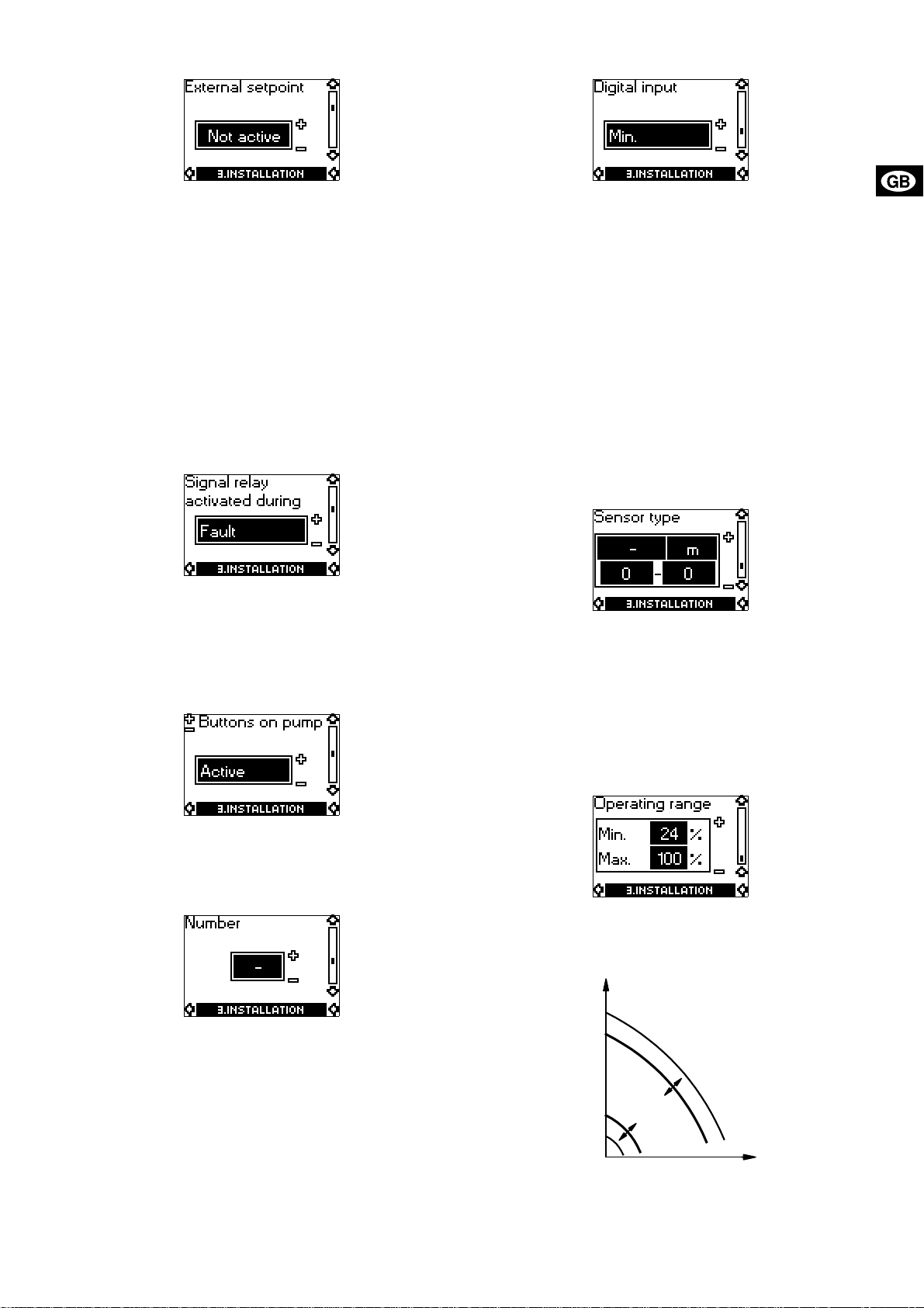
5.3.3 Selection of external setpoint signal
5.3.7 Selection of function for digital input
The input for external setpoint signal can be set to different signal
types.
Select one of the following types:
• 0-5 V (three-phase pumps only),
• 0-10 V,
• 0-20 mA,
• 4-20 mA,
• Not active.
If Not active is selected, the setpoint set by means of the R100 or
on the control panel will apply.
The setpoint set is the maximum value of the external setpoint
signal, section 7. External setpoint signal. The actual value of the
external setpoint can be read from section 5.2.1 Display of actual
setpoint.
5.3.4 Selection of fault, operating or ready signal relay
It can be selected in which situation the relay should be activated:
• Fault (fault indication),
• Operation (operating indication),
• Ready (ready indication).
See section 10. Indicator lights and signal relay.
5.3.5 Blocking of the buttons on the pump
The digital input of the pump (terminal 1, fig. 8, 9,10 or 11) can be
set to different functions.
Select one of the following functions:
• Min. (min. curve),
• Max. (max. curve).
The selected function is activated by closing the contact between
the following terminals:
• 1 and 9 of single-phase pumps (fig. 8 or 9) and
• 1 and 3 of three-phase pumps (fig. 10 or 11).
See also section 6.2 Digital input.
Min.:
When the input is activated, the pump is operating according to
the min. curve.
Max.:
When the input is activated, the pump is operating according to
the max. curve.
5.3.8 Setting of sensor
The setting of the sensor is only carried out in the case of controlled operation.
Select the following:
• Sensor output signal (0-5 V (three-phase pumps only), 0-10 V,
0-20 mA or 4-20 mA),
• sensor measuring unit (bar, mbar, m, kPa, psi, ft, m³/h, m³/s,
l/s, gpm, °C, °F or %) and
• sensor measuring range.
5.3.9 Setting of min. and max. curves
The buttons “+” and “–” on the pump can be set to:
• Active,
• Not active.
5.3.6 Allocation of pump number
A number between 1 and 64 can be allocated to the pump. In the
case of bus communication, a number must be allocated to each
pump.
Set the min. and max. curves in % of maximum performance if
the operating range must be reduced, fig. 27.
Fig. 27
H
100%
Max. curve
Op
er
a
ti
n
Min. curve
12%
g r
a
nge
Q
TM00 7747 1896
15
Page 16

• The max. curve can be adjusted within the range from maxi-
Q
Q
Q
mum performance (100%) to min. curve.
• The min. curve can be adjusted within the range from max.
curve to 12% of maximum performance. The pump has been
factory-set to 24% of maximum performance.
• The operating range lies between the min. and max. curves.
6. External forced-control signals
The pump has inputs for external signals for the forced-control
functions:
• Start/stop of pump.
• Digital function.
6.1 Start/stop input
Functional diagram: Start/stop input:
Start/stop (terminals 2 and 3)
H
Normal duty
Q
H
Stop
6.2 Digital input
By means of the R100, one of the following functions can be selected for the digital input:
•Min. curve.
•Max. curve.
Functional diagram: Input for digital function:
In controlled-operation mode, the setpoint can be set externally
within the range from the lower value of the sensor measuring
range to the setpoint set on the pump or by means of the R100,
fig. 28.
Fig. 28
Control
Parameter
Upper value of sensor measuring range
Setpoint set on pump or with the R100
Lower value of sensor measuring range
0
0
0
4
Example: At a lower differential-pressure sensor value of 0 m, a
setpoint set of 20 m and an external setpoint of 80%, the actual
setpoint will be as follows:
H
= (H
actual
In uncontrolled-operation mode, the setpoint can be set externally within the range from the min. curve to the setpoint set on
the pump or by means of the R100, fig. 29.
Fig. 29
set
= (20 - 0) x 80% + 0
= 16 m
5 V (three-phase pumps only)
10 V
20 mA
20 mA
- H
) x %
lower
external setpoint
+ H
lower
%
TM00 7669 1696
Digital function
(terminals 1 and 9 – single-phase pumps)
(terminals 1 and 3 – three-phase pumps)
H
Normal duty
Q
H
Min. curve
H
Max. curve
7. External setpoint signal
By connecting an analog signal transmitter to the input for the
setpoint signal (terminal 4), it is possible to remote-set the setpoint.
The actual external signal (0-5 V (three-phase pumps only),
0-10 V, 0-20 mA, 4-20 mA) must be selected via the R100, see
section 5.3.3 Selection of external setpoint signal.
If uncontrolled operation is selected by means of the R100, the
pump can be controlled by any controller.
Max. curve
Setpoint set on pump or with the R100
Min. curve
0
0
0
4
5 V (three-phase pumps only)
10 V
20 mA
20 mA
8. Bus signal
The pump enables serial communication via an RS-485 input.
The communication is carried out according to the GRUNDFOS
bus protocol, GENIbus protocol, and enables connection to a
building management system or another external control system.
Via the bus signal, it is possible to remote-set pump operating parameters, like setpoint, operating mode, etc. At the same time,
the pump can provide status information about impo rtant parameters, like actual value of control parameter, input power, fault indications, etc.
Contact GRUNDFOS for further details.
Note: If a bus signal is used, the number of settings available via
the R100 will be reduced.
TM00 7669 1696
16
Page 17

9. Priority of settings
The start/stop and digital inputs will influence the number of possible settings.
By means of the R100, the pump can always be se t to ma x. curve
duty or to stop.
If two or more functions are activated at the same time, the pump
will operate according to the function with the highest priority.
The priority of the settings is as shown in the following tables:
Without bus signal
Possible settings
Priority
1 Stop
2 Max. curve
3 Stop
4 Max. curve
5 Min. curve Min. curve
6 Setpoint setting Setpoint setting
Example: If, via the digital input, the pump has been forced to op-
erate according to the max. curve, the pump control panel and
the R100 can only set the pump to stop.
Control panel on
pump or R100
External
signals
With bus signal
Possible settings
Priority
1 Stop
2 Max. curve
3 Stop Stop
4 Max. curve
5 Min. curve
6
Example: If, via the digital input, the pump has been forced to op-
erate according to the max. curve, the pump control panel, the
R100 and the bus signal can only set the pump to stop.
Control
panel on
pump or
R100
External
signals
Bus signal
Setpoint
setting
17
Page 18

10. Indicator lights and signal relay
The operating condition of the pump is indicated by the green and
red indicator lights on the pump control panel, fig. 30.
Fig. 30
The pump incorporates an output for a potential-free signal via an
internal relay.
The signal output can be set to fault, operating or ready indication
by means of the R100, see section 5.3.4 Selection of fault, oper-
ating or ready signal relay.
The functions of the two indicator lights and the signal relay are
as shown in the following table:
Green
Red
Indicator lights Signal relay activated during:
Fault
(red)
Opera-
tion
(green)
Fault Operation Ready
Off Off
Off
Perman-
ently on
NCNO
C
NCNO
C
NCNO
C
NONC
C
Off Flashing
Perman-
ently on
Perman-
ently on
Perman-
ently on
Off
Perman-
ently on
Flashing
NCNO
C
NONC
C
NONC
C
NONC
C
NCNO
C
NCNO
C
NONC
C
NCNO
C
TM00 7600 1196
Description
The electricity supply has been switched off.
NCNO
C
The pump is operating.
NONC
C
The pump has been set to stop.
NONC
C
The pump has stopped because of a fault. Restarting will be
attempted (it may be necessary to restart the pump by resetting the fault indication).
NCNO
C
The pump is operating, but it has been stopped because of a
fault.
If the cause is “sensor signal outside signal range”, the pump
will continue operating according to the max. curve and the
fault indication cannot be reset until the signal is inside the
C
NONC
signal range.
If the cause is “setpoint signal outside signal range”, the
pump will continue operating according to the min. curve and
the fault indication cannot be reset until the signal is inside
the signal range.
The pump has been set to stop, but it has been stopped because of a fault.
NONC
C
A fault indication can be reset in one of the following ways:
• By briefly pressing the button “+” or “–” on the pump. This will
not change the setting of the pump.
A fault indication cannot be reset by means of “+” or “–” if the
buttons have been locked.
• By switching off the electricity supply until the indicator lights
are off.
• By means of the R100, see section 5.1.3 Fault indications.
When the R100 communicates with the pump, the red indicator
light will flash rapidly.
18
11. Megging
Note: Megging of an installation incorporating E-pumps is not al-
lowed, as the built-in electronics may be damaged.
Page 19

12. Technical data – single-phase pumps
13. Technical data – three-phase pumps
12.1 Supply voltage
1 x 200-240 V ±10%, 50/60 Hz, PE.
See nameplate.
Back-up fuse
Motor sizes from 0.37 to 1.1 kW: Max. 10 A.
Standard as well as quick-blow or slow-blow fuses may be used.
12.2 Leakage current
Earth leakage current < 3.5 mA.
The leakage currents are measured in accordance with
EN 60 355-1.
12.3 Inputs/output
Start/stop
External potential-free switch.
Voltage: 5 VDC.
Current: < 5 mA.
Screened cable.
Digital
External potential-free switch.
Voltage: 5 VDC.
Current: < 5 mA.
Screened cable.
Setpoint signals
• Potentiometer
0-10 VDC, 10 kΩ (via internal voltage supply).
Screened cable.
Maximum cable length: 100 m.
• Voltage signal
0-10 VDC, R
Tolerance: +0%/–3% at maximum voltage signal.
Screened cable.
Maximum cable length: 500 m.
• Current signal
DC 0-20 mA/4-20 mA, R
Tolerance: +0%/–3% at maximum current signal.
Screened cable.
Maximum cable length: 500 m.
Sensor signals
• Voltage signal
0-10 VDC, R
Tolerance: +0%/–3% at maximum voltage signal.
Screened cable.
Maximum cable length: 500 m.
• Current signal
DC 0-20 mA/4-20 mA, R
Tolerance: +0%/–3% at maximum current signal.
Screened cable.
Maximum cable length: 500 m.
• Electricity supply to sensor:
+24 VDC, max. 40 mA.
Signal output
Potential-free changeover contact.
Maximum contact load: 250 VAC, 2 A.
Minimum contact load: 5 VDC, 1 mA.
Screened cable: 0.5 - 2.5 mm².
Maximum cable length: 500 m.
Bus input
GRUNDFOS bus protocol, GENIbus protocol, RS-485.
0.5 - 1.5 mm²
Maximum cable length: 500 m.
*
*
*
> 50 kΩ.
i
*
= 175 Ω.
i
*
> 50 kΩ (via inter nal voltage supply).
i
*
= 175 Ω.
i
*
screened 2-core cable.
* Cross section min. 0.5 mm² and max. 1.5 mm².
13.1 Supply voltage
3 x 380-415 V ±10%, 50/60 Hz, PE.
See nameplate.
Back-up fuse
Motor sizes from 1.1 to 5.5 kW: Max. 16 A.
Motor size 7.5 kW: Max. 32 A.
Standard as well as quick-blow or slow-blow fuses may be used.
13.2 Leakage current
Motor size
[kW]
1.1 to 3.0 < 3.5
4.0 to 5.5
5.5 kW, 1400-1800 min
7.5 < 10
The leakage currents are measured in accordance with
EN 60 355-1.
-1
Leakage current
[mA]
< 5
< 10
13.3 Inputs/output
Start/stop
External potential-free switch.
Voltage: 5 VDC.
Current: < 5 mA.
Screened cable.
Digital
External potential-free switch.
Voltage: 5 VDC.
Current: < 5 mA.
Screened cable.
Setpoint signals
• Potentiometer
0-5 VDC, 10 kΩ (via internal voltage supply).
Screened cable.
Maximum cable length: 100 m.
• Voltage signal
0-5 VDC/0-10 VDC, R
Tolerance: +0%/–3% at maximum voltage signal.
Screened cable.
Maximum cable length: 500 m.
• Current signal
DC 0-20 mA/4-20 mA, R
Tolerance: +0%/–3% at maximum current signal.
Screened cable.
Maximum cable length: 500 m.
Sensor signals
• Voltage signal
0-5 VDC/0-10 VDC, R
Tolerance: +0%/–3% at maximum voltage signal.
Screened cable.
Maximum cable length: 500 m.
• Current signal
DC 0-20 mA/4-20 mA, R
Tolerance: +0%/–3% at maximum current signal.
Screened cable.
Maximum cable length: 500 m.
• Electricity supply to sensor:
+24 VDC, max. 40 mA.
Signal output
Potential-free changeover contact.
Maximum contact load: 250 VAC, 2 A.
Minimum contact load: 5 V DC, 1 mA.
Screened cable: 0.5 - 2.5 mm².
Maximum cable length: 500 m.
Bus input
GRUNDFOS bus protocol, GENIbus protocol, RS-485.
0.5 - 1.5 mm²
Maximum cable length: 500 m.
*
*
*
> 50 kΩ.
i
*
= 250 Ω.
i
*
> 50 kΩ (via internal voltage supply).
i
*
= 250 Ω.
i
*
screened 2-core cable.
* Cross section min. 0.5 mm² and max. 1.5 mm².
19
Page 20

13.4 Other technical data
EMC (electromagnetic compatibility)
EN 61 800-3.
Motors of 0.37 to 5.5 kW, except for 5.5 kW, 1400-1800 min
Residential areas - unlimited distribution,
corresponding to CISPR 11, class B, group 1.
Motors of 7.5 kW and 5.5 kW, 1400-1800 min
Residential areas - limited distribution.
Industrial areas - unlimited distribution,
corresponding to CISPR 11, class A, group 1.
When pumps fitted with motors of 7.5 kW and 5.5 kW,
1400-1800 min
-1
, are installed in residential areas, an additional
EMC filter is required to obtain class B, group 1 status.
The motor fulfils EN 50 178.
Contact GRUNDFOS for further information.
Enclosure class
Standard: IP 55 (IEC 34-5).
Insulation class
F (IEC 85).
Ambient temperature
During operation: –20°C to +40°C.
During storage/transport: –40°C to +60°C.
Relative air humidity
Maximum 95%.
-1
:
Sound pressure level
Single-phase pumps:
<70 dB(A).
-1
:
Three-phase pumps:
Motor
[kW]
1.1
Speed stated
Sound pressure
on nameplate
-1
[min
]
1400-1500 52
1700-1800 55
level
[dB(A)]
1400-1500 53
1.5
1700-1800 56
2800-3000 63
3400-3600 68
1400-1500 52
2.2
1700-1800 54
2800-3000 64
1400-1500 57
3.0
1700-1800 59
2800-3000 64
3400-3600 68
1400-1500 59
4.0
2800-3000 68
3400-3600 73
5.5
7.5
2800-3000 68
3400-3600 73
2800-3000 74
3400-3600 79
14. Disposal
Disposal of this product or parts of it must be carried out according to the following guidelines:
1. Use the local public or private waste collection service.
2. In case such waste collection service does not exist or cannot
handle the materials used in the product, please deliver the
product or any hazardous materials from it to your nearest
GRUNDFOS company or service workshop.
20
Subject to alterations.
Page 21

Denmark
GRUNDFOS DK A/S
Poul Due Jensens Vej 7A
DK-8850 Bjerringbro
Tlf.: +45-87 50 50 50
Telefax: +45-87 5 0 51 51
E-mail: info_GDK@grundfos.com
www.grundfos.com/DK
Argentina
Bombas GRUNDFOS de Argentina S.A.
Ruta Panamericana km. 37.500 Lote 34A
1619 - Garin
Pcia. de Buenos Aires
Phone: +54-3327 414 444
Telefax: +54-3327 411 111
Australia
GRUNDFOS Pumps Pty. Ltd.
P.O. Box 2040
Regency Park
South Australia 5942
Phone: +61-8-8461-4611
Telefax: +61-8-8340 0155
Austria
GRUNDFOS Pumpen Vertrieb Ges.m.b.H.
Grundfosstraße 2
A-5082 Grödig/Salzburg
Tel.: +4 3-6246-883-0
Telefax: +43-6246-883-30
Belgium
N.V. GRUNDFOS Bellux S.A.
Boomsesteenweg 81-83
B-2630 Aartselaar
Tél.: +32-3-870 7300
Télécopie: +32-3-870 7301
Brazil
GRUNDFOS do Brasil Ltda.
Rua Tomazi na 106
CEP 83325 - 040
Pinhais - PR
Phone: +55-41 668 3555
Telefax: +55-41 6 68 3554
Canada
GRUNDFOS Canada Inc.
2941 Brighton Road
Oakville, Ontario
L6H 6C9
Phone: +1-905 829 9533
Telefax: +1-905 8 29 9512
China
GRUNDFOS Pumps (Shanghai) Co. Ltd.
22 Floor, Xin Hua Lian Building
755-775 Huai Hai Rd, (M)
Shanghai 200020
PRC
Phone: +86-512-67 61 11 80
Telefax: +86-512-67 61 8 1 67
Czech Republic
GRUNDFOS s.r.o.
Cajkovského 21
779 00 Olomouc
Phone: +420-585-716 111
Telefax: +420-5 85-43 8 906
Finland
OY GRUNDFOS Pumput AB
Mestarintie 11
Piispankylä
FIN-01730 Vantaa (Helsinki)
Phone: +358-9 878 9150
Telefax: +358 -9 878 91 550
France
Pompes GRUNDFOS Distribution S.A.
Parc d’Activités de Chesnes
57, rue de Malacombe
F-38290 St. Quentin Fallavier (Lyon)
Tél.: +33-4 74 82 15 15
Télécopie: +33-4 74 94 10 51
Germany
GRUNDFOS GMBH
Schlüterstr. 33
40699 Erkrath
Tel.: +4 9-(0) 211 929 69-0
Telefax: +49-(0) 211 9 29 69-3799
e-mail: infoservice@grundfos.de
Service in Deutschland:
e-mail: kundendienst@grundfos.de
Greece
GRUNDFOS Hellas A.E.B.E.
20th km. Athinon-Markopoulou Av.
P.O. Bo x 71
GR-19002 Peania
Phone: +0030-210-66 83 400
Telefax: +0030-210-66 46 273
Hong Kong
GRUNDFOS Pumps (Hong Kong) Ltd.
Unit 1, Ground floor
Siu Wai Industrial Centre
29-33 Wing Hong Street &
68 King Lam Street, Cheung Sha Wan
Kowloon
Phone: +852-27861706/27861741
Telefax: +852-2785866 4
Hungary
GRUNDFOS Hungária Kft.
Park u. 8
H-2045 Törökbalint,
Phone: +36-34 520 100
Telefax: +36-34 520 200
India
GRUNDFOS Pumps India Private Limited
Flat A, Ground Floor
61/62 Chamiers Aptmt
Chamiers Road
Chennai 600 028
Phone: +91-44 432 3487
Telefax: +91-44 432 3489
Indonesia
PT GRUNDFOS Pompa
Jl. Rawa Sumur III, Blok III / CC-1
Kawasan Industri, Pulogadung
Jakarta 13930
Phone: +62-21-460 6909
Telefax: +62-21-460 6910/ 460 690 1
Ireland
GRUNDFOS (Ireland) Ltd.
Unit 34, Stillorgan Industrial Park
Blackrock
County Dublin
Phone: +353-1-2954926
Telefax: +353-1-2954739
Italy
GRUNDFOS Pompe Italia S.r.l.
Via Gran Sasso 4
I-20060 Truccazzano (Milano)
Tel. : +39-02-95838 112
Telefax: +39-02-9530929 0/9583846 1
Japan
GRUNDFOS Pumps K.K.
1-2-3, Shin Miyakoda
Hamamatsu City
Shizuoka pref. 431-21
Phone: +81-53-428 4760
Telefax: +81-53-484 1014
Korea
GRUNDFOS Pumps Korea Ltd.
6th Floor, Aju Building 679-5
Yeoksam-dong, Kang nam-ku, 135-91 6
Seoul Korea
Phone: +82-2-5317 600
Telefax: +82-2-5633 725
Malaysia
GRUNDFOS Pumps Sdn. Bhd.
7 Jalan Peguam U1/25
Glenmarie Industria l Park
40150 Shah Alam
Selangor
Phone: +60-3-5569 2922
Telefax: +60-3-5569 2866
Mexico
Bombas GRUNDFOS de Mexico S.A. de C.V.
Boulevard TLC No. 15
Parque Industrial Stiva Aeropuerto
Apodaca, N.L. 66600
Mexico
Phone: +52-81-8144 4000
Telefax: +52-81-8144 4010
Netherlands
GRUNDFOS Nederland B.V.
Postbus 104
NL-1380 AC Weesp
Tel. : +31-294-492 21 1
Telefax: +31-294-49 2244/4922 99
New Zealand
GRUNDFOS Pumps NZ Ltd.
17 Beatrice Tinsley Crescent
North Harbour Industr ial Estate
Albany, Auckland
Phone: +64-9-415 3240
Telefax: +64-9-415 32 50
Norway
GRUNDFOS Pumper A/S
Strømsveien 344
Postboks 235, Leirdal
N-1011 Oslo
Tlf.: +47-22 90 47 00
Telefax: +47-22 32 21 50
Poland
GRUNDFOS Pompy Sp. z o.o.
ul. Klonowa 23
Baranowo k. Poznania
PL-62-081 Przezmierowo
Phone: +48-61-650 13 00
Telefax: +48-61-650 13 50
Portugal
Bombas GRUNDFOS Portugal, S.A.
Rua Calvet de Magalhães, 241
Apartado 1079
P-2770-153 Paço de Arcos
Tel. : + 351 -2 1-440 7 6 00
Telefax: +351-21-440 76 90
Russia
OOO GRUNDFOS
Shkolnaya 39
RUS-109544 Moscow
Phone: +7-095 564 88 00, +7-095 7 37 30 00
Telefax: +7-095 564 88 11, +7-095 737 75 36
e-mail: grundfos.moscow@grundfos.com
Singapore
GRUNDFOS (Singapore) Pte. Ltd.
24 Tuas West Road
Jurong Town
Singapore 638381
Phone: +65-6865 1222
Telefax: +65-6861 8402
Spain
Bombas GRUNDFOS España S.A.
Camino de la Fuentecilla, s/n
E-28110 Algete (Madrid)
Tel. : + 34-91 -848 88 00
Telefax: +34-91-628 0465
Sweden
GRUNDFOS AB
Box 63, Angeredsvinkeln 9
S-424 22 Angered
Tel. : + 46-771-32 23 00
Telefax: +46-31 331 94 60
Switzerland
GRUNDFOS Pumpen AG
Bruggacherstrasse 10
CH-8117 Fällanden/ZH
Tel. : + 41-1-806 811 1
Telefax: +41-1-806 81 15
Taiwan
GRUNDFOS Pumps (Taiwan) Ltd.
14, Min-Yu Road
Tu nglo Indus tr ial Park
Tunglo, Miao-Li County
Tai wan, R.O.C .
Phone: +886-37-98 05 57
Telefax: +886-37-98 05 70
Thailand
GRUNDFOS (Thailand) Ltd.
947/168 Moo 12, Bangna-Trad Rd., K.M. 3,
Bangna, Phrakanong
Bangkok 10260
Phone: +66-2-744 1785 ... 91
Telefax: +66-2-744 17 75 ... 6
Turkey
GRUNDFOS POMPA SAN. ve TIC. LTD. STI
Bulgurlu Caddesi no. 32
TR-81190 Üsküdar Istanbul
Phone: +90 - 216-4280 306
Telefax: +90 - 216-3279 988
United Arab Emirates
GRUNDFOS Gulf Distribution
P.O. Box 16768
Jebel Ali Free Zone
Dubai
Phone: +971-4- 8815 166
Telefax: +971-4-8815 136
United Kingdom
GRUNDFOS Pumps Ltd.
Grovebury Road
Leighton Buzzard/Beds. LU7 8TL
Phone: +44-1525-850000
Telefax: +44-1525 -8500 11
U.S.A.
GRUNDFOS Pumps Corporation
17100 West 118th Terrace
Olathe, Kansas 66061
Phone: +1-913-227-3400
Telefax: +1-913-227-3500
Addresses revised 06.11.2003
Page 22

Being responsible is our foundation
Being responsible is our foundation
Thinking ahead makes it possible
Thinking ahead makes it possible
Innovation is the essence
Innovation is the essence
96 40 57 42 0203
Repl. 96 40 57 42 1002
www.grundfos.com
134
 Loading...