

Page 1
We understand water.
Water Softener | softliQ:MC
Operation manual
Page 2

Central Contact
Germany
Sales
Phone +49 9074 41-0
Technical Service
Phone +49 9074 41-333
Fax +49 9074 41-120
Availability
Monday to Thursday
7:00 am – 6:00 pm
Friday
7:00 am – 4:00 pm
Your local point of contact: see
accompanying list of
representatives
Copyright
The manufacturer reserves the copyright to this manual. No part of this manual may be reproduced
in any way without the written permission of Grünbeck Wasseraufbereitung GmbH, nor may any part
be processed, duplicated or disseminated using electronic systems.
Violations of the aforementioned requirements shall be subject to compensation.
We reserve the right to modifications.
© by Grünbeck Wasseraufbereitung GmbH
Translation of the original operation manual
Edition of the operation manual: August 2018
Order no.: TD3-BM000en_064
Page 3

Table of contents
3 | 80
BA_TD3-BM000en_064_softliQ-MC.docx
Table of contents
1
About this manual ............................................... 4
1.1Other applicable documents ................................ 4
1.2Target group ........................................................ 4
1.3Storage of documents .......................................... 4
1.4Symbols used ...................................................... 4
1.5Typographical conventions .................................. 5
1.6Validity of the manual .......................................... 6
1.7Type plate ............................................................ 7
2Safety ................................................................... 8
2.1Safety measures .................................................. 8
2.2Technical safety instructions ................................ 9
2.3Regulations .......................................................... 9
2.4Responsibilities of the specialist installer and/or
the specialist company ...................................... 10
2.5Responsibilities of the owner/user ..................... 10
2.6Permitted regenerant ......................................... 10
3Product description .......................................... 11
3.1Intended use ...................................................... 11
3.2Product components .......................................... 11
3.3Functional description ........................................ 12
3.4Features ............................................................. 13
3.5Product registration ............................................ 14
3.6Accessories ....................................................... 15
4Control unit ........................................................ 17
4.1Overview ............................................................ 17
4.2Displays ............................................................. 17
4.3Navigating the control unit ................................. 19
4.4Menu structure ................................................... 20
4.5Code-protected levels ........................................ 22
4.6"myGrünbeck" app ............................................. 24
4.7Peer-to-peer connection .................................... 25
4.8Connection via Wi-Fi router ............................... 26
4.9Sending an email if there is a malfunction ......... 31
5Installation ......................................................... 33
5.1Requirements in relation to the installation site . 33
5.2Checking the scope of supply ............................ 35
5.3Installing the product .......................................... 35
6Start-up .............................................................. 40
6.1Starting up the product ...................................... 40
6.2Hand over the product to the owner/user togehter
with the operation manual ..................................44
7Operation ............................................................45
7.1Retrieving information .........................................45
7.2Starting a manual regeneration ..........................46
7.3Settings ...............................................................47
7.4Select regeneration time .....................................48
7.5Setting the current date and time .......................48
7.6Setting the time of the fixed regeneration ...........48
7.7Determining and entering the water hardness ....49
7.8Refilling salt tablets .............................................51
8Cleaning, inspection, maintenance ..................52
8.1Cleaning .............................................................52
8.2Inspection ...........................................................53
8.3Maintenance .......................................................53
8.4Consumables ......................................................55
8.5Spare parts .........................................................55
8.6Wearing parts .....................................................56
9Troubleshooting .................................................57
9.1Display messages ..............................................57
9.2Other observations .............................................61
10Shut-down and restart .......................................62
10.1Shut-down ..........................................................62
10.2Restart ................................................................62
11Dismantling and disposal .................................63
11.1Dismantling .........................................................63
11.2Disposal ..............................................................63
12Technical specifications ...................................65
13Other information ...............................................67
13.1Explanation of terminology .................................67
13.2Sodium content in the water ...............................67
13.3Hardness ranges ................................................68
14Operation log ......................................................69
Page 4
About this manual
4 | 80
BA_TD3-BM000en_064_softliQ-MC.docx
1 About this manual
1.1 Other applicable documents
The following documents shall be deemed as applicable documents for the softliQ:MC:
● For Grünbeck's technical service/authorised service company:
Technical service manual for softliQ:MC water softener
Order no.: TD4-BM000en
● In addition, the manuals of all accessories used do apply.
1.2 Target group
This manual is intended for specialist installers and owners/users.
1.3 Storage of documents
Keep this manual and all other applicable documents, so that they are available when
needed. Make sure that your specialist installer enters the proper start-up and annual
maintenance in the operation log in chapter 14 .
1.4 Symbols used
This symbol identifies information and instructions and that you must comply with for your
personal safety as well as to avoid damage to property.
This symbol identifies information and instructions that you must comply with in order to
avoid damage to property.
This symbol identifies important information about the product or its handling.
This symbol identifies work that may only be carried out by a specialist installer. In
Germany, the installation company must be registered in an installation directory of a water
supply company acc. to §12(2) AVB Wasser V (German Ordinance on General Conditions
for the Supply of Water).
This symbol designates tasks that may only be performed by Grünbeck's technical
service/authorised service company or by specialist installers trained by Grünbeck.
This symbol identifies work that may only be performed by electronically trained personnel
in accordance with the VDE guidelines or according to the guidelines of similar local
institutions.
Page 5

About this manual
5 | 80
BA_TD3-BM000en_064_softliQ-MC.docx
1.5 Typographical conventions
The following typographical conventions are used in this manual:
1.5.1 Menu paths
Menu paths are shown in a different font. The sequence of the menus is indicated by the ">"
sign.
Status level>Menu level>Manual regeneration
1.5.2 Menu items
Menu items, e.g. within a software menu, are highlighted in grey.
Menu item
1.5.3 Buttons
Buttons are depicted with a dotted frame.
Button
1.5.4 Instructions
Single-step instructions or instructions where the sequence of the actions is unimportant are
indicated as follows:
► Action
Multi-step instructions where the sequence of the steps must be observed are indicated as
follows:
1. First step (level 1)
a - First subdivision of the step (level 2)
b - Second subdivision of the step (level 2)
2. Second step (level 1)
Results of an instruction are indicated as follows:
» Result
Page 6

About this manual
6 | 80
BA_TD3-BM000en_064_softliQ-MC.docx
1.5.5 Lists
Bullet points used:
● First bullet point (level 1)
• First bullet point (level 2)
• Second bullet point (level 2)
● Second bullet point (level 1)
1.6 Validity of the manual
This manual applies to the following products:
● Water softener softliQ:MC32
● water softener softliQ:MC38
Page 7
About this manual
7 | 80
BA_TD3-BM000en_064_softliQ-MC.docx
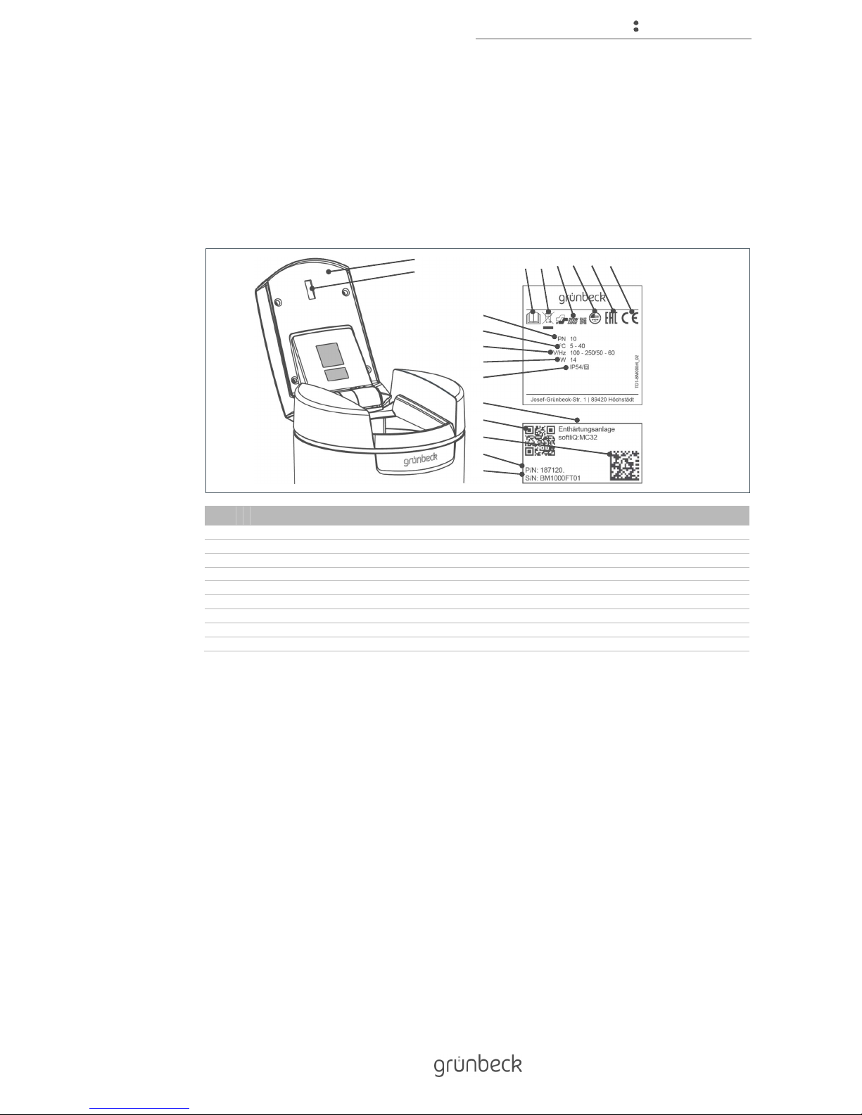
1.7 Type plate
The type plate is located under the lid of the brine tank.
Please specify the data shown on the type plate in order to speed up the processing of your
inquiries or orders. Therefore enter the necessary information in the table below to have it
readily available whenever necessary.
Item Designation Item Designation
1 Brine tank lid 2 Pre-alarm salt supply
3 Observe operation manual 4 Disposal information
5 SVGW test mark 6 DVGW test mark
7 EAC mark 8 CE mark
9 Nominal pressure 10 Ambient temperature
11 Power supply 12 Power input
13 Protection class 14 Product designation
15 QR code 16 Data matrix code
17 Order no. 18 Serial no.
● Product designation: Water softener softliQ:MC__
● Order no.: 187___
● Serial no.: ________________
2
3 8
9
16
14
13
15
10
12
18
17
1 76
5
4
11
Page 8
Safety
8 | 80
BA_TD3-BM000en_064_softliQ-MC.docx
2 Safety
WARNING: Contamination of drinking water due to improper handling.
● Risk of infectious diseases.
► Have the installation, start-up and annual maintenance carried out by specialist
installers only.
2.1 Safety measures
● Carefully read this manual before operating your product.
● Install the product in a frost-free room. Otherwise, the system may suffer
irreparable damage. Water damage may occur as a result.
● Only use genuine spare parts for maintenance or repair. If unsuitable spare parts
are used, the warranty for your product will be void.
● Do not use products which have a damaged power supply cable. This can lead to
injuries due to electric shock. Have damaged power supply cables replaced without
delay.
● Mains cables may only be replaced by the manufacturer or by authorised
personnel.
● Comply with the hygiene instructions in chapter 8. Failure to comply can result in
microbiological contamination of your drinking water installation.
● Only have persons working on your system that have read and understood the
present manual and that are qualified to do such work based on their vocational
training.
● Only operate the product if all components are installed properly.
● Safety devices must never be removed, bridged or otherwise tampered with.
● This product can be used by children over 8 years of age and persons with limited
abilities or lack of experience if they are supervised or instructed in the safe use of
the product and do understand the resulting hazards.
● Cleaning and maintenance must not be carried out by children.
● Keep the product away from children.
Page 9

Safety
9 | 80
BA_TD3-BM000en_064_softliQ-MC.docx
2.2 Technical safety instructions
This manual contains information and instructions that you must comply with for your
personal safety as well as to avoid damage to property. The information and instructions are
highlighted by a warning triangle and have the following structure:
CAUTION: Type and source of danger.
● Possible consequences
► Preventive measures
The following signal words are defined according to the degree of danger, and may be used
in this document:
● DANGER means that serious or fatal injuries will occur if the corresponding
precautionary measures are not taken.
● WARNING means that serious or fatal injuries may occur if the corresponding
precautionary measures are not taken.
● CAUTION means that damage to property may occur if the corresponding
precautionary measures are not taken.
● NOTE (without a warning triangle) means that damage to property may occur if the
corresponding safety measures are not taken.
2.3 Regulations
When installing and starting up the system, amongst others, comply with the following
regulations and guidelines:
● Statutory regulations on environmental protection
● Provisions of the employers' liability insurance company
● DIN EN 806 Specifications for installations inside buildings conveying water for
human consumption
● VDI 6023 Parts 5 to 7
Page 10

Safety
10 | 80
BA_TD3-BM000en_064_softliQ-MC.docx
2.4 Responsibilities of the specialist installer and/or the
specialist company
Comply with the following instructions to ensure the proper and safe functioning of the
product:
● Only perform activities described in this manual.
● Perform all activities in accordance with all applicable standards and regulations.
● Brief the owner/user on the function and operation of the product.
● Advise the owner/user of the maintenance of the product.
● Inform the owner/user about possible dangers that can arise during operation of
the product.
2.5 Responsibilities of the owner/user
Comply with the following instructions to ensure the proper and safe functioning of the
product:
● Arrange for a specialist installer to carry out installation, start-up and maintenance.
● Have the product explained to you by the specialist installer.
● Only perform activities described in this manual.
● Do not carry out any activities that are explicitly marked for a specialist installer.
● Only use this product as intended.
● Make sure that the required inspection and maintenance work is carried out.
● Keep this manual.
2.6 Permitted regenerant
The softliQ:MC water softener may only be operated with the following regenerant:
● Salt tablets according to EN 973 type A
Other regenerants are not allowed.
Page 11
Product description
11 | 80
BA_TD3-BM000en_064_softliQ-MC.docx
3 Product description
3.1 Intended use
● The softliQ water softener may only and exclusively be used for the softening and
partial softening of cold drinking water.
● The softliQ water softener protects water pipes and connected water-carrying
systems from scaling or from malfunctions and damage caused by scaling.
● The softliQ:MC32 water softener is designed for the continuous supply of houses
of 1 up to 8 units (max. 20 persons) with soft water.
● The softliQ:MC38 water softener is designed for the continuous supply of houses
of 3 up to 12 units (max. 30 persons) with soft water.
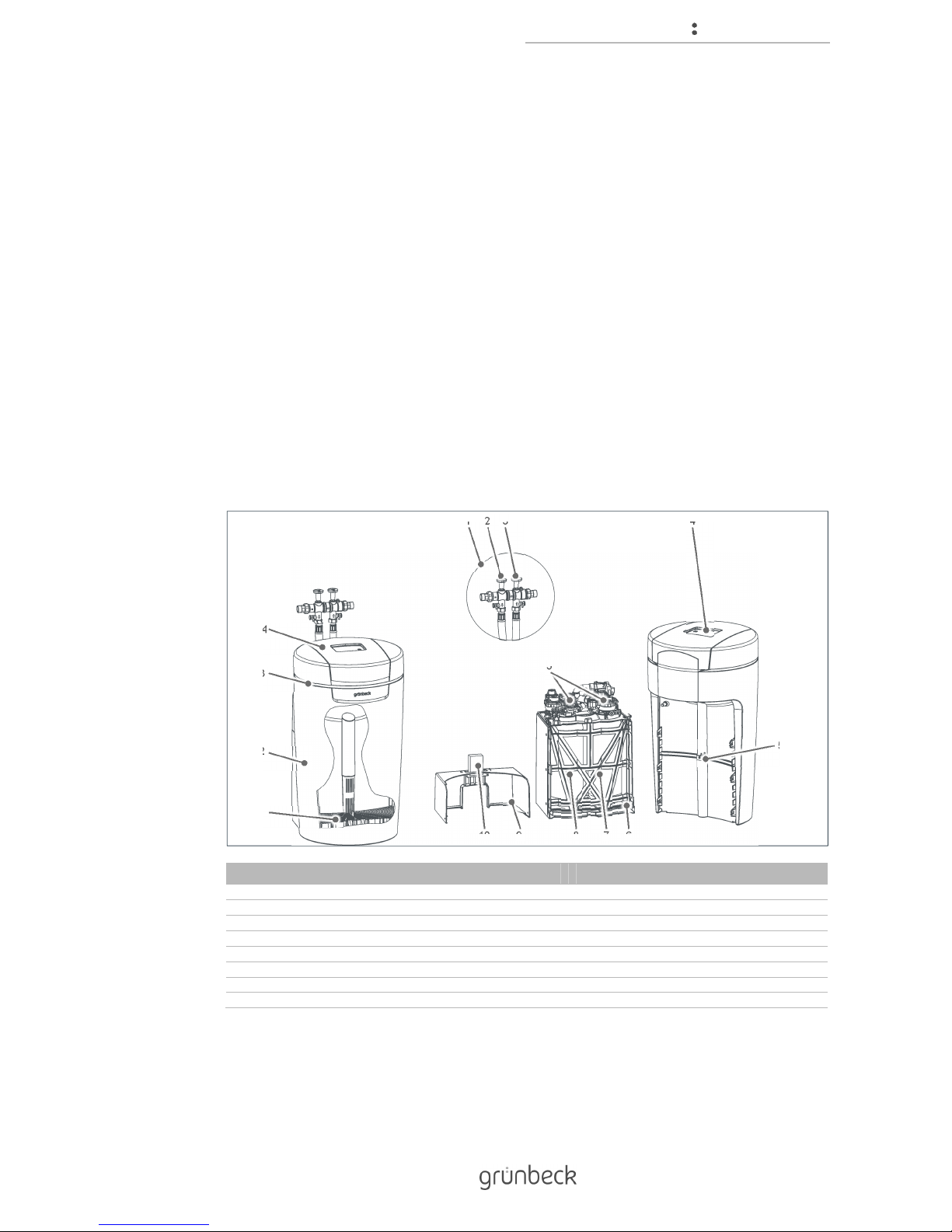
3.2 Product components
Item Designation Item Designation
1 Connection block 2 Shut-off valve for raw water
3 Shut-off valve for soft water 4 Control unit
5 Brine valve 6 Housing of technical equipment, lower part
7 Exchanger 2 8 Exchanger 1
9 Housing of technical equipment, upper part 10 Water test kit "total hardness“
11 Sieve bottom 12 Brine tank
13 Illuminated LED ring 14 Brine tank lid
15 Control valves
2 3
1 4
5
67
15
9 10
11
12
14
13
8
Page 12
Product description
12 | 80
BA_TD3-BM000en_064_softliQ-MC.docx
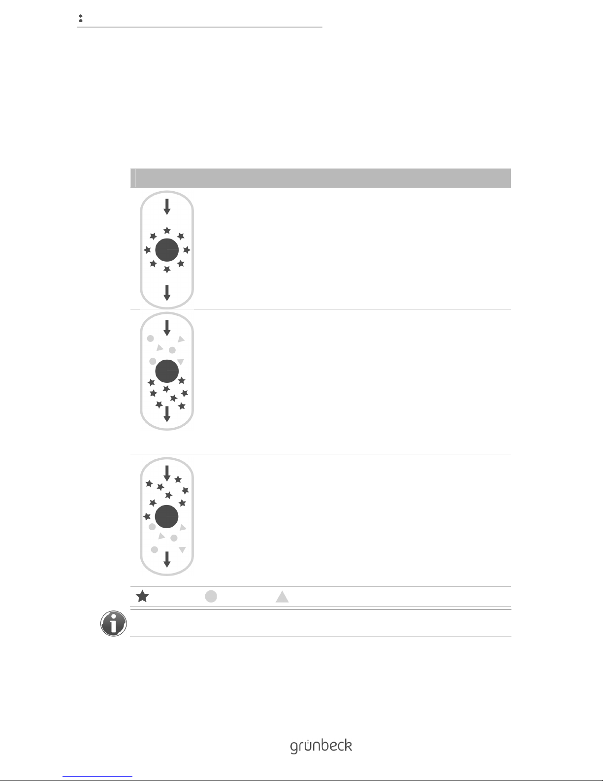
3.3 Functional description
3.3.1 Ion exchange process
The softliQ water softener works according to the ion exchange process. The exchange of
calcium and magnesium ions for sodium ions causes the water to become soft.
Figure Explanation
The exchanger contains ion exchanger resin in the form of small resin
beads.
Sodium ions adhere to each resin bead.
Hard water containing lots of calcium and magnesium ions flows through
the exchanger.
The ion exchanger resin absorbs calcium and magnesium ions from the
water in exchange for sodium ions.
This reaction is called ion exchange.
The calcium and magnesium ions are retained in the exchanger.
Soft water without calcium and magnesium ions, but containing sodium
ions, leaves the exchanger.
This process continues until no more sodium ions are available. The ion
exchanger resin is exhausted.
The exchange can be reversed if a large amount of sodium ions is
added.
The exchanger is rinsed with brine (water containing salt).
By their sheer number, sodium ions displace calcium and magnesium
ions on the ion exchanger resin.
This water containing calcium and magnesium ions is discharged to the
drain.
The initial condition is restored.
The ion exchanger resin is regenerated, and thus ready for operation.
Sodium ion Calcium ion Magnesium ion
Your dishwasher works according to the ion exchange process, too.
Page 13

Product description
13 | 80
BA_TD3-BM000en_064_softliQ-MC.docx
3.3.2 Intelligence of the softliQ:MC water softener
Based on the consumption values of the past four weeks, the system capacity is
automatically adjusted to the individual water consumption of the owner/user.
A regeneration is released, if at least 50 % of the current system capacity is used up. The
point of regeneration automatically is placed in a time period where usually little water is
consumed. The point of regeneration can also be set at a fixed time.
During each regeneration, only the used-up system capacity is regenerated and only as
much salt is used as necessary. No later than after four days without regeneration, the
system releases a complete regeneration, as required by DIN standard 19636-100, for
hygienic reasons.
The intelligence of the softliQ water softener allows for an efficient operation at the lowest
salt and power consumption possible.
3.3.3 Function
The softliQ:MC water softener features four modes (selections):
● Eco
Minimum use of resources in case of normal consumption.
● Power
Maximum performance for highest demands.
● Comfort
Optimum use of resources and system performance.
● Individual
To enter your own user profile.
3.4 Features
3.4.1 Electronically controlled blending unit
The electronically controlled blending unit automatically regulates the ratio between fully
softened water and raw water. The regulation is subject to the raw and soft water hardness
programmed in the control unit.
Page 14
Product description
14 | 80
BA_TD3-BM000en_064_softliQ-MC.docx
3.4.2 Pre-alarm salt supply
Once per regeneration, a light sensor checks the filling level of the regeneration salt. If the
filling level of the regeneration salt is low, the control unit provides feedback in the form of a
warning message. This is shown by a yellow symbol in the control unit. If the level falls below
the minimum filling level, the control unit calculates how many days the salt supply is
expected to last and indicates this value in days.
The days the salt supply is expected to last are calculated based on the water consumption
of the past days. In case of fluctuating water consumption, the indicated range of the salt
supply also fluctuates.
3.4.3 Illuminated LED ring
The illuminated LED ring illuminates the brine tank and is a visual signal to indicate operating
states. The illuminated LED ring may be programmed to the following functions:
● Is illuminated during water treatment
● Is illuminated during operation of the control unit
● Intermittent flashing in case malfunctions do occur
● Intermittent flashing in case of pre-alarm salt supply
If desired, the illuminated LED ring can be set to continuous illumination or be deactivated
completely (refer to chapter 4.4).
3.5 Product registration
If you register your product, the warranty for this product will be extended by one year.
You have the following options to register your product:
● Registration on Grünbeck's website (www.gruenbeck.com).
● Registration using the myGrünbeck app (refer to chapter 4.6).
Page 15
Product description
15 | 80
BA_TD3-BM000en_064_softliQ-MC.docx
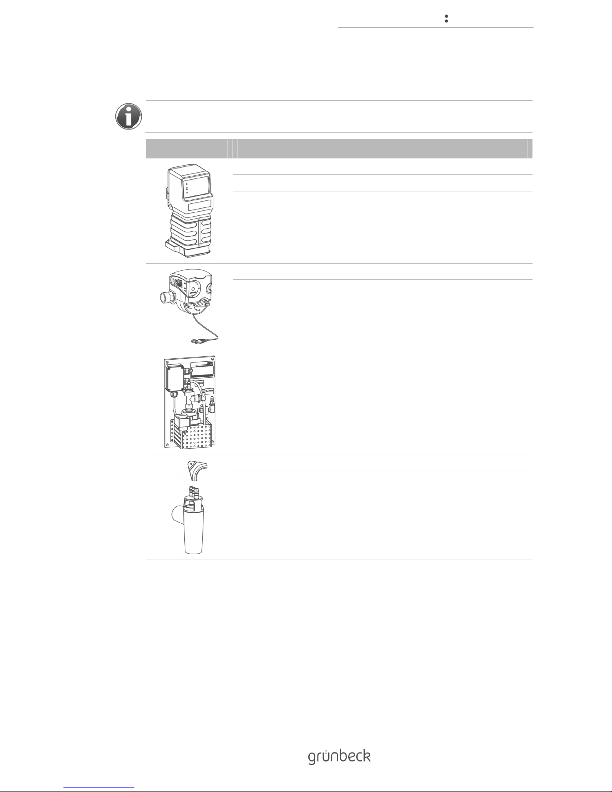
3.6 Accessories
You can retrofit your product with accessories. Please contact your local Grünbeck
representative or Grünbeck’s headquarters in Hoechstaedt for details.
Figure Product Order no.
EXADOS dosing computer EK 6 softliQ:MC 115 570
EXADOS dosing computer ES 6 softliQ:MC 115 580
Electronically controlled dosing technology for corrosion protection or
to stabilise the total hardness.
Safety device protectliQ:A20 126 400
Product for protection against water damage in one- and two-family
homes.
For other sizes, please inquire.
Regeneration water delivery pump 188 800
To discharge the regeneration water into drain pipes located at a
higher level.
Drain connection DN 50 188 875
For professional installation acc. to DIN EN 1717.
Page 16
Product description
16 | 80
BA_TD3-BM000en_064_softliQ-MC.docx
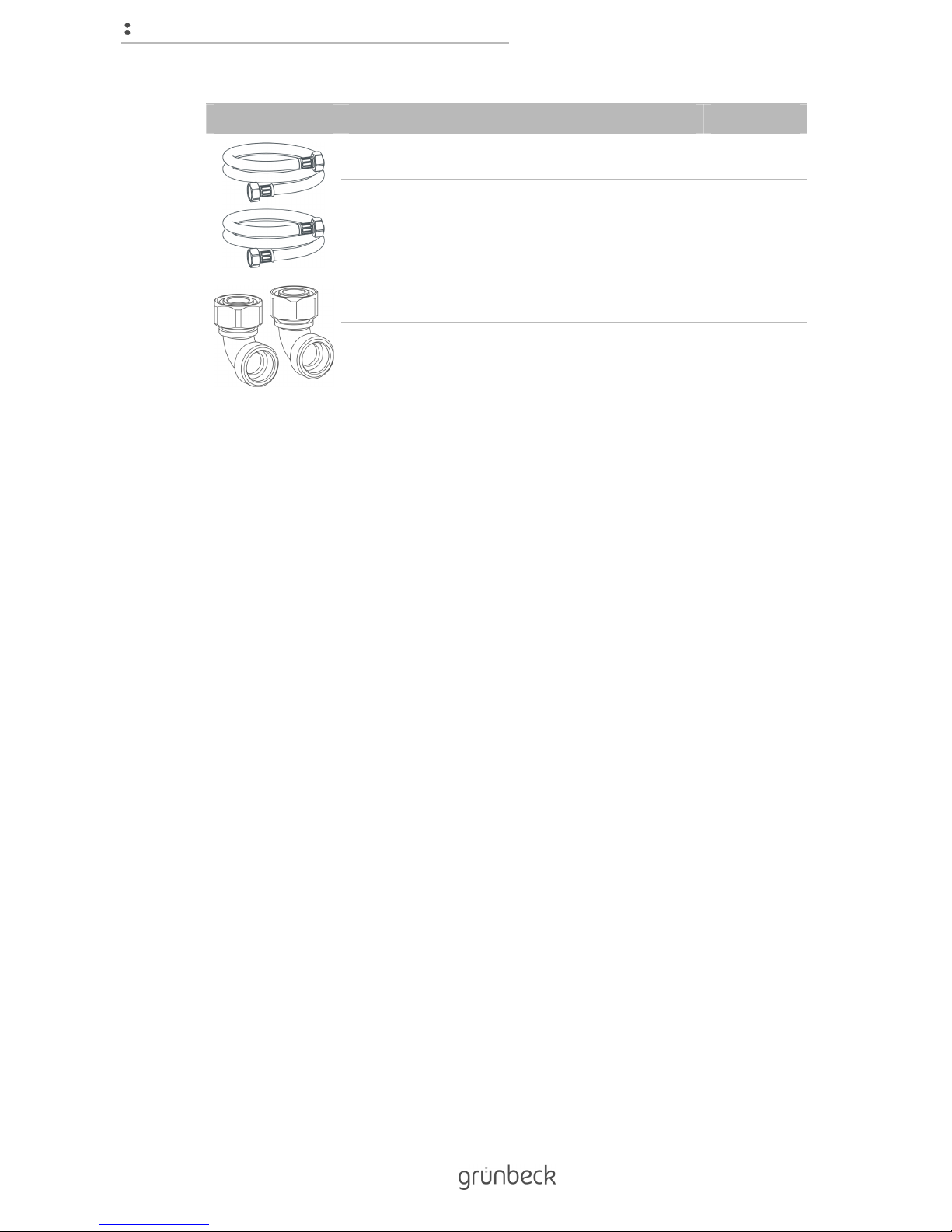
Figure Product Order no.
Extension kit for connection hoses DN25
(MC32)
187 660e
Extension kit for connection hoses DN32
(MC38)
187 680e
To extend the hose to 1.6 m.
90° connection angle – 1" (2x)
(MC32)
187 865
To direct the connection hoses closer along the softliQ in case of
confined installation conditions.
Page 17
Control unit
17 | 80
BA_TD3-BM000en_064_softliQ-MC.docx
4 Control unit
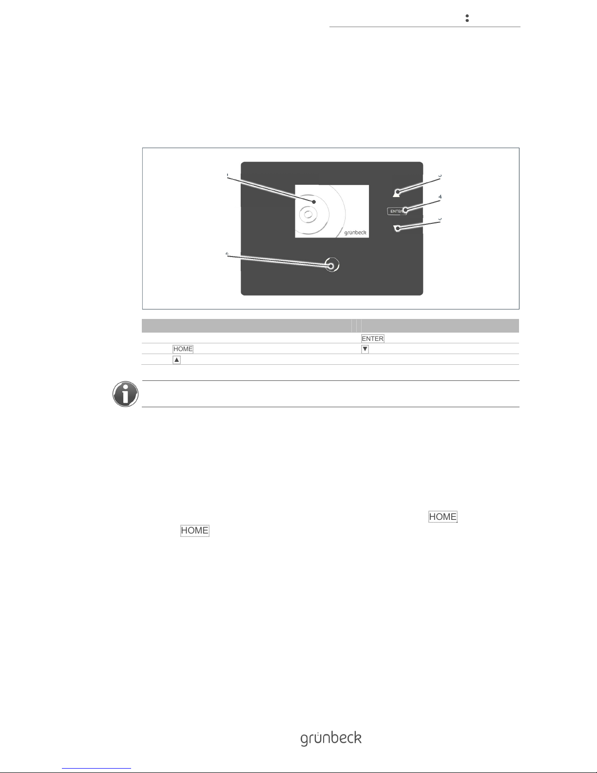
4.1 Overview
Item Designation Item Designation
1 Display 4
ENTER key
2
HOME button
5
▼ Down arrow key
3
▲ Up arrow keys
Only those keys light up, which currently have a function assigned.
4.2 Displays
4.2.1 Status level
The status level is the basic display of your water softener. It provides you with information
on the current status. As standard, the display is switched off and only HOME is illuminated.
Pressing HOME briefly activates the display.
If the menu level is selected but no button is pressed for more than 2 minutes, the control
unit returns to the status level and the display turns off. Parameters that have not been
saved are discarded.
2
1
3
4
5
Page 18
Control unit
18 | 80
BA_TD3-BM000en_064_softliQ-MC.docx
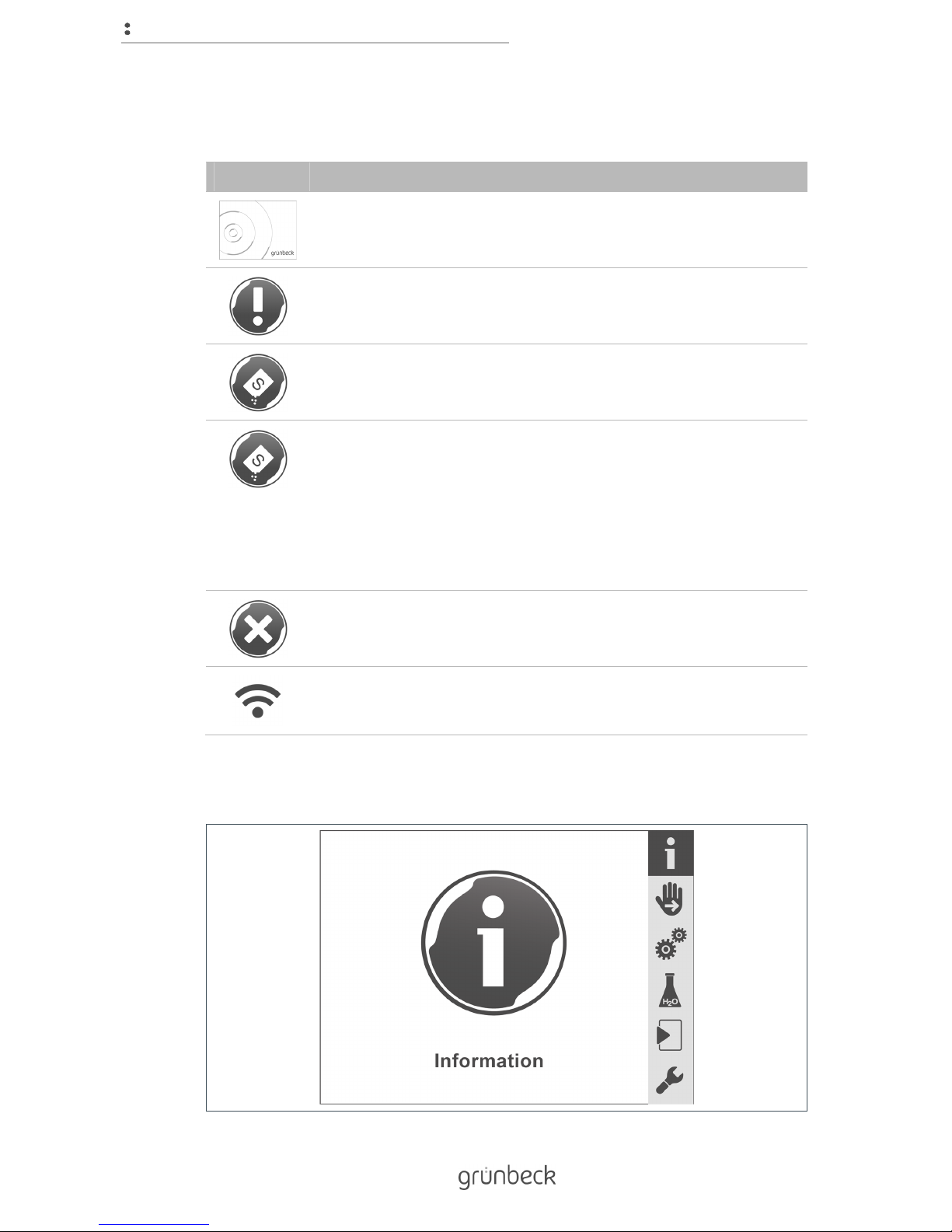
The following messages are displayed in the status level:
Figure Explanation
The water softener is working properly.
Yellow symbol
Service due!
Notify Grünbeck's technical service/authorised service company.
Yellow symbol
Salt supply low! Please refill! Still sufficient for xy days
Red symbol
Salt supply used up! Refill immediately!
The water softener is not working properly.
1. Refill salt.
2. Wait for 10 minutes.
3. Perform a manual regeneration (refer to chapter 7.2).
Red symbol
The water softener is not working properly. A malfunction has occurred
(refer to chapter 9.1).
Wi-Fi symbol
This is displayed when there is a Wi-Fi connection with a router.
4.2.2 Menu level
Page 19
Control unit
19 | 80
BA_TD3-BM000en_064_softliQ-MC.docx
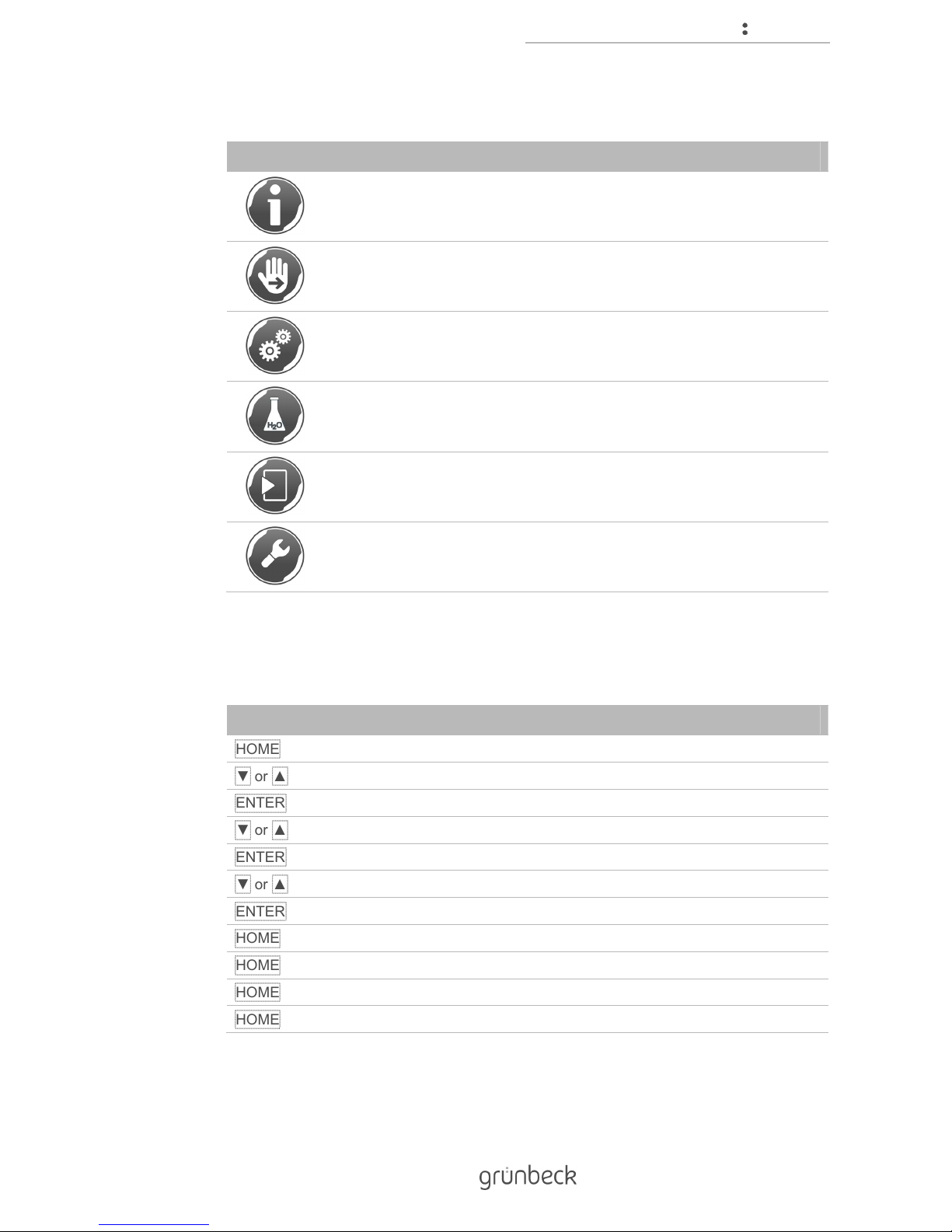
In the menu level, you may select the following submenus:
Figure Explanation
Information
This menu offers useful information on the water softener (refer to
chapter 7.1).
Manual regeneration
In this menu, you can manually release a regeneration (refer to
chapter 7.2).
Settings
In this menu, you can adapt your water softener individually (refer to
chapter 7.3).
Water hardness
In this menu, you can enter the values of the prevailing raw water and the
desired soft water hardness (refer to chapter 7.7).
Start-up
In this menu, you can start the automatic start-up program (refer to
chapter 6.1).
Technical service
The technical service menu is reserved for Grünbeck's technical
service/authorised service company and is protected by a code.
4.3 Navigating the control unit
Step Designation
HOME
Call up the menu level from the status level
▼ or ▲
Scroll through the menu level
ENTER
Select submenu
▼ or ▲
Scroll to the menu items
ENTER
Activate value or selection
▼ or ▲
Change values or select setting
ENTER
Accept value or setting
HOME
Do not save value or setting (cancel procedure)
HOME
Back to the menu level
HOME
Back to the status level
HOME
Call up the menu level from the status level
Page 20
Control unit
20 | 80
BA_TD3-BM000en_064_softliQ-MC.docx
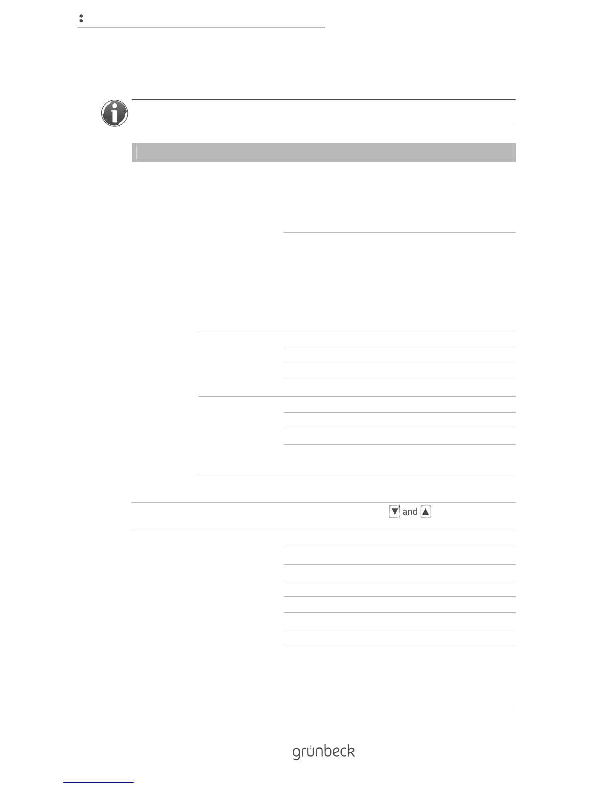
4.4 Menu structure
For more information about the contents of the menu level, refer to chapter 7.
Menu level Menu items Values/settings
Information Information 1 During operation
Graphic depiction of the system capacity of each
exchanger (two blue symbols).
Indication of operating mode
Eco/Power/Comfort/Individual
During regeneration: Graphic depiction of the
operating state of each exchanger
Grey symbol: Exchanger is being regenerated
Blue symbol: Exchanger is in operation
Current regeneration step
Fill brine tank/salting/slow rinse/
backwash/washing out
Information 2 System flow rate
Days the salt supply is expected to last
Raw water hardness
Actual soft water hardness
Information 3 Regeneration counter
Soft water volume meter (0 °dH)
Password for app connection
Perform maintenance in xx days
(only if activated)
Information 4 Contact data,e.g. of your installer
Name/phone number/e-mail address
Manual
regeneration
-
To start, press and hold ▼ and ▲ for 2 seconds.
Settings Change language German
English
French
Italian
Dutch
Russian
Spanish
Chinese
Page 21
Control unit
21 | 80
BA_TD3-BM000en_064_softliQ-MC.docx
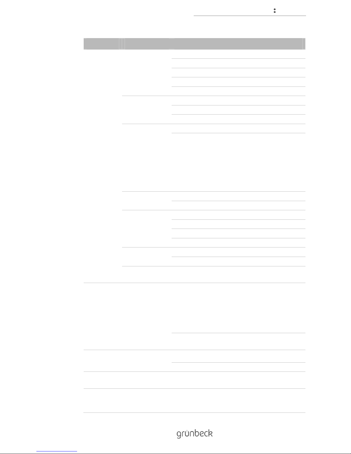
Menu level Menu items Values/settings
Change hardness
unit
°dH
°f
°e
ppm
mol/m³
Date/time Setting the time
Current date
Automatic switch-over from DST to ST
Configure Wi-Fi Release of Wi-Fi module (activated/deactivated)
Configure Wi-Fi
Search for Wi-Fi (start/back)
Display of Wi-Fi networks found
Display of Wi-Fi network connected to
Enter password
Wi-Fi network status
App network status
Select
regeneration time
Automatic
Fixed
Function Eco
Power
Comfort
Individual
Display in standby Activated
Deactivated
Set maintenance
interval
Setting in days
Illuminated LED
ring
function
Illuminated LED ring function
During water treatment, operation, malfunction
During operation, malfunction
During malfunction
Deactivated
Illuminated continuously
Illuminated LED ring is flashing in case of pre-alarm
salt supply (yes/no)
Water
hardness
Water hardness Set raw water hardness
Setpoint of soft water hardness
Start-up Start-up Follow the instructions indicated in the display of the
softliQ:MC
Technical
service
Code-protected
area
The settings described here may only be made by
Grünbeck's technical service/authorised service
company.
Page 22
Control unit
22 | 80
BA_TD3-BM000en_064_softliQ-MC.docx
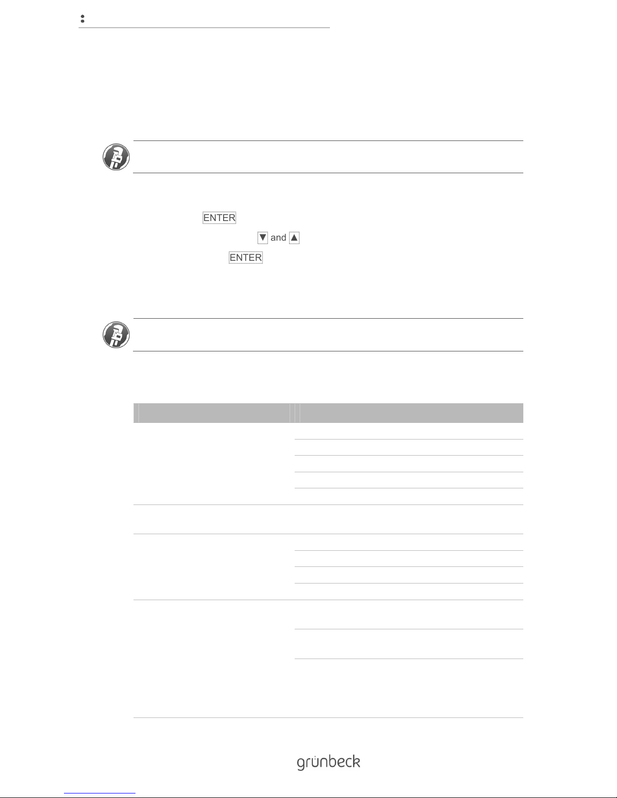
4.5 Code-protected levels
The settings described here may only be made by Grünbeck's technical service/authorised
service company.
Status level>Menu level>Technical service
1. Touch ENTER briefly.
2. Enter the code with ▼ and ▲.
3. Confirm with ENTER.
4.5.1 Installer level (code 005)
The settings described here may only be made by Grünbeck's technical service/authorised
service company.
In the extended installer Level, additional parameters and values can be modified:
Menu items Settings/remarks
Information
exchanger 1
(indication only) Current flow [m³/h]
Capacity figure [m³ x °dH]
Remaining capacity [m³]
Regeneration step [min.] or [l]
Last regeneration [date/time] over [%]
Information
exchanger 2
(indication only) As for exchanger 1
Blending
information
Current flow [m³/h]
Setpoint of soft water hardness [°dH]
Actual soft water hardness value [°dH]
Actual raw water hardness value [°dH]
Flow rates (indication only) Parallel operation
Peak value x.xx [m³/h] for xxxxx [min.]
Exchanger 1
Peak value x.xx [m³/h] for xxxxx [min.]
Exchanger 2
Peak value x.xx [m³/h] for xxxxx [min.]
Page 23
Control unit
23 | 80
BA_TD3-BM000en_064_softliQ-MC.docx
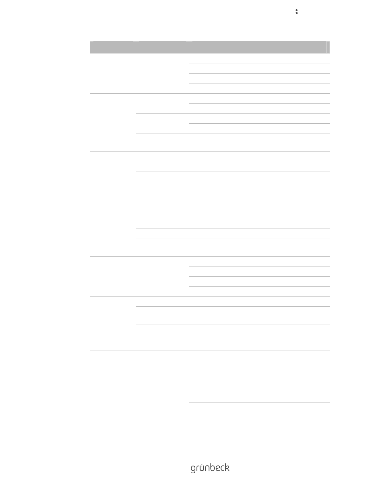
Menu items Settings/remarks
Water volumes Soft water exchanger 1 [m³]
Soft water exchanger 2 [m³]
Raw water blending [m³]
Make-up volume [l]
Soft water
sample
Exchanger 1 0 – Factory setting
1 – Carry out function
Exchanger 2 0 – Factory setting
1 – Carry out function
Perform soft water sampling for selected exchanger. After completion,
the factory setting is activated again.
Find reference
position
regeneration
valve
Regeneration
valve exchanger 1
0 – Factory setting
1 – Carry out function
Regeneration
valve exchanger 2
0 – Factory setting
1 – Carry out function
Move to reference position of the selected exchanger. Ongoing
regenerations are aborted. After completion, the factory setting is
activated again.
Fill operating
water volume
into brine tank
Deactivated – factory setting
Activated – Carry out function
Fill the brine tank to a minimum water level (e.g. after cleaning the brine
tank). After completion, the factory setting is activated again.
Start test
regeneration
0 – Factory setting
both – both control valves in succession
2 – only exchanger 2
1 – only exchanger 1
Select
regeneration
time
Automatic Factory setting
Fixed Programming of 1 – 3 fixed regeneration times.
Regeneration only takes place, if required.
Weekly timer
regeneration time
1/2/3
Mon ... Sun
Time of the regeneration on each day of the week
(factory setting: Mon – Fri at 7:00 am)
Inputs and
outputs
Voltage-free
contact function
Regeneration water delivery pump (factory setting)
Contact closed during the regeneration steps
salting, slow rinse, backwash and washing out.
This setting must be made in connection with the
regeneration water delivery pump available as an
accessory (refer to chapter 3.6).
Regeneration message
Contact closed during the entire regeneration.
Page 24
Control unit
24 | 80
BA_TD3-BM000en_064_softliQ-MC.docx
Menu items Settings/remarks
Configuration of
fault signal
contact
N. C. (factory setting)
Contact closed if mains voltage is applied and there
is no malfunction.
N. O.
Contact closed in the event of a malfunction.
Programmable
input function
Release of regeneration (factory setting)
Start of a complete regeneration if the contact at the
programmable input closes.
Regeneration lock
The regeneration lock is active as long as the
contact at the programmable input is closed;
manually released and automatic regenerations
after a power failure take priority.
Fault signal forwarding
When the contact opens, a text stored using the
myGrünbeck app is sent as an e-mail.
If (in conjunction with the function voltage-free
contact>forwarding of fault signals)
additional devices are connected, the text stored for
sending e-mails can be modified in the myGrünbeck
app accordingly.
4.6 "myGrünbeck" app
1. You can find the "myGrünbeck" app in Google Play, the App Store or any other
marketplace.
2. Install the myGrünbeck app.
The myGrünbeck app supports IOS from version 5.0 onwards and Android
from version 4.0. Refer to the instructions of your mobile device for more
detailed information about installing an app.
You can register your product conveniently using the myGrünbeck app. In the
myGrünbeck app, call up the "Product registration" function in the "User"
menu. Scan the data matrix code on the type plate (refer to chapter 0).
Registering your product will earn you a follow-on warranty for your product.
Page 25

Control unit
25 | 80
BA_TD3-BM000en_064_softliQ-MC.docx
4.7 Peer-to-peer connection
You can connect Wi-Fi devices such as smart phones, tablets or laptops directly to the
control unit of the softliQ and thus permit access to the control unit.
This connection is particularly convenient for specialist installers for the start-up and
maintenance of the softliQ.
A peer-to-peer connection is also possible if there is an existing connection via Wi-Fi
router. Up to 5 connections can be established simultaneously.
1. Search for available Wi-Fi connections in the settings of your Wi-Fi- device.
For information about connecting your Wi-Fi device (e.g. smart phone or
tablet) to a Wi-Fi network, refer to the instruction manual of your device.
2. Select the SSID of your water softener (softliQ:MC_XXXXXX).
3. Enter the 8-digit password.
The password that you need for your connection can be found here:
Status level>Menu level>Information>
Information3>Password for app connection
» You are connected to the softliQ's control unit.
Once the connection has been established, it is possible to access the water softener via the
internal webpage or using the myGrünbeck app. The connection will only be established
after the password has been entered.
Page 26

Control unit
26 | 80
BA_TD3-BM000en_064_softliQ-MC.docx
4.8 Connection via Wi-Fi router
You can connect the control unit of the softliQ to a Wi-Fi router, and thus integrate it into an
existing network. You will then be able to access the control unit of the softliQ via your Wi-Fi
network. This connection is particularly suitable for the owner/user of the softliQ water
softener.
The control unit of the softliQ has 4 buttons. These must be used for making all entries.
Therefore, we recommend establishing the connection via the internal webpage or the
myGrünbeck app.
It may happen that the connection is dropped if your router changes to the economy mode
with reduced transmission power. Refer to the instruction manual of your router to learn
how to switch off the economy mode.
NOTE: Invisible SSIDs are not detected by the control unit.
● The control unit cannot be integrated into an existing Wi-Fi network with an
invisible SSID.
► Activate transmission of the SSID temporarily.
Note: The connection may be dropped if the DHCP function of your router is active.
● The system cannot be operated via an external device.
► In the settings of your router, set the connection to "static DHCP". Refer to the
instruction manual of your router to learn how to set this function.
Page 27

Control unit
27 | 80
BA_TD3-BM000en_064_softliQ-MC.docx
4.8.1 Connect the softliQ to Wi-Fi using the myGrünbeck app
In order to be able to configure the water softener using the myGrünbeck app, you must
already have an existing peer-to-peer connection (refer to chapter 4.7).
1. Open the menu of the myGrünbeck app.
2. Select Settings.
3. Choose Wi-Fi configuration.
» You will see a screen with "Wi-Fi network status" and "Access point network
status".
» Under "Access point network status", you will see the SSID, IP address and status
of an existing peer-to-peer connection.
If there is no connection, no information will be displayed under "Wi-Fi
network status".
4. Activate Search for networks.
» Available networks are displayed.
5. Select your network.
6. Enter the password of your network.
7. Confirm the entry.
» If the Wi-Fi connection was established successfully, the Wi-Fi symbol () will
appear in the top left-hand corner of the display.
4.8.2 Connect the softliQ to the Wi-Fi network by using the internal Webpage.
NOTE: Access to the internal webpage is not possible if an unsuitable browser is used and
if JavaScript is not activated.
● You will not be able to configure your product using the internal webpage or read
out data.
► Install a current version of Internet Explorer (IE10 or higher) and activate
JavaScript.
You must already have a peer-to-peer connection so that the water softener can be
configured using the internal webpage (refer to chapter 4.7).
You can find the IP address of the internal webpage here:
Settings>Configure Wi-Fi >App network status
Page 28

Control unit
28 | 80
BA_TD3-BM000en_064_softliQ-MC.docx
1. Enter "http://192.168.0.1/" in the address bar of your brower.
2. Confirm the entry.
3. Select Wi-Fi configuration in the menu bar on the left-hand side.
4. In the table on the right-hand side, next to the Search for Wi-Fi item, activate Start.
The search can take up to one minute.
» All available networks are displayed under "Connect to Wi-Fi network". These are
named as "Wi-Fi network 1" to "Wi-Fi network X".
5. Activate Connect next to the SSID of your router.
6. Enter the Wi-Fi password of your router.
The login can take up to one minute.
Page 29

Control unit
29 | 80
BA_TD3-BM000en_064_softliQ-MC.docx
» If the login has been successful, "Connected" is displayed under "Wi-Fi network
status". The Wi-Fi symbol ( ) will appear in the top left-hand corner of the display
of the softliQ:MC control unit.
If the connection process takes longer than two minutes, disconnect the Wi-Fi
connection of your Wi-Fi device. Start the connection process again as
described in chapter 4.8.
4.8.3 Connecting the softliQ to the Wi-Fi network via the control unit
Status level>Menu level>Settings>Configure Wi-Fi>Wi-Fi module
1. Check whether "activated" was selected.
2. If "deactivated" was selected, press ENTER.
3. Select "activated".
4. Confirm with ENTER.
5. Press ▼.
Status level>Menu level>Settings>Configure Wi-Fi>Configure Wi-Fi
6. Press ENTER.
7. Select "Start".
8. Confirm with ENTER.
» All Wi-Fi networks within range are displayed.
9. Confirm with ENTER.
10. Select the SSID of your Wi-Fi .
The selected Wi-Fi is indicated by "-" next to the SSID.
11. Confirm with ENTER.
12. Press ▼.
» SSID of the selected Wi-Fi network is displayed.
13. Press ▼.
Status level>Menu level>Settings>Configure Wi-Fi>Enter password
14. Confirm with ENTER.
15. Enter the Wi-Fi password of your router.
Page 30

Control unit
30 | 80
BA_TD3-BM000en_064_softliQ-MC.docx
The characters appear in this sequence when ▼ is pressed:
!"#$%&'()*+,-/0123456789:;<=>?@ABCDEFGHIJKLMNOPQRSTUVWXYZ
[\]^_`abcdefghijklmnopqrstuvwxyz{|}~
Press ▼ again if the letters cease to change. If you entered a position
incorrectly, you may return to the beginning with HOME.
16. Confirm each position with ENTER.
17. Complete the entry by pressing ENTER for at least 5 seconds.
The login can take up to one minute.
18. Press ▼.
» Wi-Fi network status is displayed. The Wi-Fi symbol ( ) will appear in the top left-
hand corner of the display.
4.8.4 Checking the connection to your Wi-Fi router
If there are other Wi-Fi capable Grünbeck products in the vicinity, an unintended connection
to your Wi-Fi router may be established.
Status level>Menu level>Settings>Configure Wi-Fi
1. Press ▲.
Status level>Menu level>Settings>Configure Wi-Fi>App network status
2. Write down the SSID of your water softener.
softliQ:MC_ _ _ _ _ _ _
3. Check that this matches the SSID displayed on your router.
Refer to the instructions of your router for more detailed information on the
procedure for displaying the devices that are connected to your router.
Page 31

Control unit
31 | 80
BA_TD3-BM000en_064_softliQ-MC.docx
4.9 Sending an email if there is a malfunction
The control unit of your softliQ water softener can notify you via email if there is a
malfunction. You can use an email service provided by Grünbeck or your own email account
for this purpose.
4.9.1 Using the e-mail service provided
If you would like to use the email service provided by Grünbeck, proceed as follows:
1. Go to www.gruenbeck.de/myaccount.
2. Follow the instructions.
» You will receive an email containing all necessary data.
The email will be sent by "noreply@prodreggb.de" and its subject is "Confirmation of user
agreement". You can search for it in your inbox. If you do not find the email in your inbox,
check your spam folder.
The email function can only be set up using the myGrünbeck app or the internal webpage.
4.9.2 Using your own email account
To configure the email sending function, you require the following data of your e-mail
account:
● Email address from which you are sending
● SMTP server
● Port
● Account
● Password
4.9.3 Configuring the email function
The following steps cannot be carried out unless there is an existing Wi-Fi connection as
described in chapter 4.8.
If you have concluded a maintenance contract, you can have an e-mail sent directly to your
specialist installer. Please discuss that with him/her.
Page 32

Control unit
32 | 80
BA_TD3-BM000en_064_softliQ-MC.docx
CAUTION: Incorrect e-mail settings will prevent you from being notified if there is a
malfunction.
● Malfunctions that are not remedied can lead to hygiene problems.
► Once you have completed the e-mail configuration, send a test email to check the
settings.
Data required for e-mail configuration
● Data from the email of the email service provided by Grünbeck or of your email
provider:
• Email address from which you are sending
• SMTP server and port
• Account (user name)
• Password
● Personal data:
• Email address to which the email should be sent (up to 3)
• Telephone number and last name of the owner/user
There is no need to enter a telephone number and last name. If entered, the
data will appear in the subject line of the email, and this will make it easier for
the recipient (installer, caretaker) to make the correct categorisation.
• Email text for subject line
The email text for the subject line is only used if the malfunction to be
transferred is triggered by the programmable input (refer to chapter 4.9).
Using the myGrünbeck app:
1. Open the menu of the myGrünbeck app.
2. Select Settings.
3. Select Email configuration .
4. Enter the necessary data.
5. Send a test email to make sure it is working.
Using the internal webpage:
1. Enter "http://192.168.0.1/" in the address bar of your brower.
2. Confirm the entry.
3. Select "Networks" in the menu bar on the left-hand side.
4. Enter the required data in the table under Email configuration.
5. Send a test email to make sure it is working.
Page 33

Installation
33 | 80
BA_TD3-BM000en_064_softliQ-MC.docx
5 Installation
The installation of a water softener represents a major intervention into the drinking water
system and may only be performed by a specialist installer.
Item Designation Item Designation
1 Safety device protectliQ 2 Drinking water filter pureliQ
3 Garden water pipe 4 Water withdrawal point
5 EXADOS dosing computer 6 Drain connection DN 50 acc. to DIN EN 1717
5.1 Requirements in relation to the installation site
Observe local installation directives, general guidelines and technical specifications. The
installation site must be frost-proof and ensure the system's protection from chemicals, dyes,
solvents and vapours.
Always install a drinking water filter and, if required, a pressure reducer (e.g. fine filter
pureliQ:KD) upstream of the system. A shock-proof socket is required within a distance of
approx. 1.2 m of the system. For the discharge of the regeneration water, a drain connection
(DN 50) must be available.
NOTE: The system will not function without continuous power supply.
● No soft water will be available if the system is operated without power.
► Do not interconnect the socket with a light switch, heating emergency switch or
the like.
2
5
4
6
1
3
Page 34

Installation
34 | 80
BA_TD3-BM000en_064_softliQ-MC.docx
NOTE: The valves of the system are electrically operated.
● Water can flow to the drain unchecked if there is a power failure during
regeneration.
► If there is a power failure, check your product and shut off the water supply, if
necessary.
The installation room must be provided with a floor drain. If none is available, an appropriate
safety device has to be installed to prevent water damage. We recommend using a
protectliQ safety device (refer to chapter 3.6).
If the softened water is intended for human consumption within the meaning of the German
Drinking Water Ordinance, the ambient temperature must not exceed 25 °C. For applications
that are purely technical, the ambient temperature must not exceed 40 °C.
NOTE: Malfunction of the lifting system if there is a power failure.
● Water damage in case the lifting system fails.
► Secure your water installation against inadvertent water leakage if there is a
power failure.
NOTE: Functional failure if lifting systems are not resistant to salt water.
● Water damage in case the lifting system fails.
► Use a salt water-resistant lifting system, or our regeneration water delivery pump
(refer to chapter 3.6).
Page 35

Installation
35 | 80
BA_TD3-BM000en_064_softliQ-MC.docx
5.2 Checking the scope of supply
Item Designation Item Designation
1 Water softener completely pre-assembled 2 2 Connection hoses
3 Connection block incl. 2 inserts, union nuts, gaskets
each
4 Water test kit "total hardness“
5 Operation manual
► Check the scope of supply for completeness and possible damage.
5.3 Installing the product
WARNING: Danger of contaminated drinking water due to stagnation.
● Risk of infectious diseases.
► In accordance with VDI 6023, do not connect your product to the drinking water
installation until directly before start-up.
5.3.1 Fitting the connection block into the pipe
1. Pay attention to the sieve insert and the flow direction.
2. Install the connection block into the pipe with inserts, union nuts and gaskets.
2
534
1
Page 36

Installation
36 | 80
BA_TD3-BM000en_064_softliQ-MC.docx
5.3.2 Installing the connection hoses
1. Unscrew both the screws on the sides of the upper part of the housing of the
technical equipment.
2. Remove the upper part of the housing of the technical equipment.
3. Mount the connection hoses.
NOTE: Mix-up of connection hoses and insufficient tightening torque of union
nuts possible.
● Functional failure and/or leaks at the system.
► Observe the flow direction marked by arrows.
► Tighten the union nuts with approx. 4 Nm.
Page 37

Installation
37 | 80
BA_TD3-BM000en_064_softliQ-MC.docx
5.3.3 Establish waste water connection as per DIN EN 1717
The drain connection DN 50 as per DIN EN 1717 for small-scale water softeners makes it
easier to connect according to the DIN standard (refer to chapter 3.6).
NOTE: Backing up of wastewater due to kinked hoses.
● Risk of water damage.
► Run the hoses to the drain with a downward slope and without kinks and bends.
Page 38

Installation
38 | 80
BA_TD3-BM000en_064_softliQ-MC.docx
1. Shorten the flushing water hose (outside diameter 12 mm) to the required length.
2. Fasten the flushing water hose (regeneration water flows out under pressure).
3. Shorten the overflow hose (outside diameter 16 mm) to the required length.
4. Run the overflow hose to the drain with a downward slope.
5. Fasten the overflow hose.
6. Make sure there is a free outlet to the drain.
If a water flow pressure of at least 3.0 bar is available, the flushing water
hose can be laid up to max. 2.2 m above the floor level. Then, the connection
of the overflow hose of the brine tank is not possible.
» This completes the installation.
After completion of the installation, slide the protective cover from the packaging over the
water softener. This protects the water softener from contamination until it is started up.
Page 39

Installation
39 | 80
BA_TD3-BM000en_064_softliQ-MC.docx
5.3.4 Inputs and outputs of the control unit
The control unit features a voltage-free input and output. These are configured in the installer
level (refer to chapter 4.5).
Item Designation Item Designation
1 Programmable input DigIN 3 Voltage-free fault signal contact Pot.f.S. (NO)
max. 230 V/max. 1 A
2 Voltage-free contact Prog.Out
max. 230 V/max. 1 A
Use the following connection cables tor connection to the programmable input or voltagefree output of the control unit:
● Flexible cables of quality H03xx F 2x0.5 mm² or comparable for connecting the
programmable input (no. 1), because only voltage-free contacts may be connected.
● Flexible cables of quality H05xx F 2x0.75 mm² or comparable for connecting the
voltage-free output (no. 2), because consumers operated with mains voltage may
be connected.
3
1
2
Page 40

Start-up
40 | 80
BA_TD3-BM000en_064_softliQ-MC.docx
6 Start-up
6.1 Starting up the product
The softliQ control unit is operated using keys (refer to chapter 4.3).
The start-up program assists you with starting up the softliQ water softener. You are guided
through the start-up procedure step-by-step on the display.
There are dots on the right of the display. These provide orientation and show you where in
the program you are at present. The current position is shown in a darker colour. Values can
only be changed if the corresponding dot is shown in green. Use the ▲ or ▼ keys to
navigate through the program. Open menus with ENTER.
6.1.1 Initial start-up and automatic start of the start-up program
1. Keep salt tablets (refer to chapter 2.6) handy.
2. Remove the protective film from the display.
3. Plug in the mains plug.
4. Select the required language with ▲ or ▼.
5. Confirm with ENTER.
6. Select the desired hardness unit with ▲ or ▼.
7. Confirm with ENTER.
8. Enter your app password.
You only need your app password if you want to put the product into
operation using the myGrünbeck app. Otherwise, skip this step.
Page 41

Start-up
41 | 80
BA_TD3-BM000en_064_softliQ-MC.docx
9. Select Start-up START.
10. Confirm with ENTER.
11. Continue with chapter 6.1.3.
6.1.2 Manual start of the start-up program
If required, start the start-up program manually from the menu level.
Status level>Menu level>Start-up
1. Confirm with ENTER.
2. Press and hold ▲ and ▼ for 2 seconds.
6.1.3 Program flow of the start-up program
There may be wait periods during the start-up program. These are indicated in the
control unit by means of an hourglass symbol. Continuing with the program is only
possible upon completion of the wait period and the disappearance of the symbol.
Use the ▲ or ▼ keys to navigate through the program.
1. Do not fill any water into the brine tank.
2. Confirm with ▼.
3. Fill salt tablets into the brine tank (refer to chapter 7.8).
4. Confirm with ▼.
5. Set the current time and the current date.
a Set the desired value using▲ and ▼.
b Confirm with ENTER.
The system moves to its reference point. In case the reference point has not
been reached until after the entry of the time, the remaining time will be
indicated in the display.
6. Determine the raw water hardness. You have the following options to do so:
• Contact your water supply company and ask them what the value is.
• Determine the value by using the water test kit supplied with the system (refer
to chapter 7.7).
7. Use ▲ and ▼ to set the value for the raw water hardness.
8. Confirm with ENTER.
Page 42

Start-up
42 | 80
BA_TD3-BM000en_064_softliQ-MC.docx
Confirmation is only possible if the system has completed the previous step.
This is the case when the ENTER key lights up. The value can be changed
later (refer to chapter 7.7).
Item Designation Item Designation
1 Shut-off valve for raw water 2 Shut-off valve for soft water
3 Sampling valve for raw water 4 Sampling valve for soft water
9. Open the raw water shut-off valve at the connection block.
10. Confirm with ▼.
11. Check for leaks.
12. Confirm with ▼.
Water flows through the flushing water hose to the drain. This is completely
normal during start-up.
13. Press ENTER to start the venting program.
2
3
4
1
Page 43

Start-up
43 | 80
BA_TD3-BM000en_064_softliQ-MC.docx
» The display indicates "Remaining time 22:00 min". The counter counts down to
00:00 min. If this is completed, the next display message will be indicated.
In exceptional cases, start-up may be aborted (remaining time runs down to
00:00 minutes and nothing else happens). In this case, proceed as follows:
► Disconnect the mains plug.
► Wait for 5 seconds.
► Start again from point 6.1.1.
Should, after some time, "raw water shut-off valve at connection block still
closed" appear in the display, open the shut-off valve for raw water.
14. Open the soft water shut-off valve.
15. Confirm with ▼.
16. Check the water hardness on exchanger 1 as described in chapter 7.7.
» Upon confirmation with ENTER, exchanger 1 is put out of operation and exchanger
2 is put into operation.
17. Check the water hardness on exchanger 2 as described in chapter 7.7.
18. Confirm with ▼.
With these tests, the function of the exchangers is checked. The water
sample must have a hardness of less than 1 °dH.
19. Use ▲ and ▼ to set the desired value for the soft water hardness.
• Recommendation for Germany: Soft water hardness 3 - 6 °dH.
• Recommendation for Austria: Soft water hardness at least 8.4 °dH.
Take the maximum admissible sodium concentration of your drinking water
into consideration (refer to chapter 13.2).
20. Press ENTER to start the test regenerations.
» The remaining time will be indicated in the display. The remaining time for the
regeneration of both exchangers is counted down.
The test regenerations take approx. 33 minutes for both exchangers.
In exceptional cases, a malfunction may be indicated at the end of the test regeneration. In
this case, proceed as follows:
► Confirm with ENTER.
► Restart the start-up program.
► Call Grünbeck's technical service/authorised service company if the malfunction
occurs again.
Page 44

Start-up
44 | 80
BA_TD3-BM000en_064_softliQ-MC.docx
6.2 Hand over the product to the owner/user togehter with the
operation manual
When handing over the product, proceed as follows:
1. Inform the owner/user how the water softener works.
2. Hand over all documents to the owner/user for storage.
3. Use the manual to brief the owner/user, and answer any questions.
4. Inform the owner/user about the need for inspections and maintenance.
5. Inform the owner/user about the influence of the water hardness on the dosage of
detergents and cleaning agents.
Page 45

Operation
45 | 80
BA_TD3-BM000en_064_softliQ-MC.docx
7 Operation
7.1 Retrieving information
Status level>Menu level>Information
7.1.1 Information 1
Here, you see a graphic display of the current system function.
Figure Explanation
Both exchangers are in operation. The system capacity
declines from the top downwards. One bar corresponds to 20
%. The light bars show the available system capacity.
Below the symbols, the current mode is indicated:
Eco/Power/Comfort
One exchanger is in operation, the other is being regenerated.
The bars of the grey symbol correspond to the following
regeneration steps from the bottom upwards:
Fill brine tank (lowermost bar)
Salting
Slow rinse
Backwash
Washing out (highest bar)
Below the symbols, the regeneration step is indicated.
Explanation of symbols:
Blue symbol
Grey symbol
7.1.2 Information 2
Display Explanation
System flow rate Indicates the current flow rate of the system. The value is
displayed in m³/h.
Days the salt supply is
expected to last
Indicates for how long the salt supply is estimated to last. The
value is displayed in days.
Raw water hardness Indicates the set raw water hardness. The value is displayed in
the selected hardness unit.
Actual soft water
hardness
Indicates the set soft water hardness. The value is displayed in
the selected hardness unit.
Page 46

Operation
46 | 80
BA_TD3-BM000en_064_softliQ-MC.docx
7.1.3 Information 3
Display Explanation
Regeneration counter Indicates how many regenerations have been performed.
Soft water volume
meter
Indicates in m³ how much soft water has been withdrawn from
the system.
Password for app
connection
Indication of the password to establish the connection between
the control unit and the myGrünbeck app installed on a mobile
device
Perform maintenance
in xx days
(only if activated)
Indicates in how many days the next maintenance is due.
7.1.4 Information 4
Display Explanation
Contact data Indication of contact data, for instance, of your installer
(name, phone number, email address).
Entry only possible via app or website.
7.2 Starting a manual regeneration
Status level>Menu level>Manual regeneration
A manual regeneration is necessary in the following cases:
● The product resumes operation after a longer period of standstill.
● After maintenance and repair work has been performed.
● If the raw water hardness has changed or has been altered.
● After a longer power failure.
Both exchangers will be regenerated one after the other with the maximum capacity figure.
Page 47

Operation
47 | 80
BA_TD3-BM000en_064_softliQ-MC.docx
7.3 Settings
Status level>Menu level>Settings
You can change the following values:
Menu item Setting options
Change language German (factory setting)
English
French
Italian
Dutch
Russian
Spanish
Chinese
Change hardness unit °dH (factory setting)
°f
°e
ppm
mol/m³
Date, time Set the time
Current date
Automatic switch-over from DST to ST
Configure Wi-Fi Refer to chapter 4.8
Select regeneration time Automatic (factory setting)
Fixed
Function Eco
Power
Comfort (factory setting)
Individual
Display behaviour in standby Activated
Deactivated (factory setting)
Set maintenance interval 000 days (factory setting)
Page 48

Operation
48 | 80
BA_TD3-BM000en_064_softliQ-MC.docx
Menu item Setting options
Illuminated LED ring function Illuminated LED ring function
During water treatment, operation, malfunction
(factory setting)
During operation, malfunction
During malfunction
Deactivated
Illuminated continuously
Illuminated LED ring is flashing in case of pre-alarm
salt supply
yes
no (factory setting)
7.4 Select regeneration time
Status level>Menu level>Settings>Select regeneration time
1. Press ENTER.
2. Use ▲ and ▼ to select the desired setting.
a Automatic (factory setting)
b Fixed
3. Confirm with ENTER.
7.5 Setting the current date and time
Status level>Menu level>Settings>Date, time>Set current time
1. Press ENTER.
2. Use ▲ and ▼ to set the time.
3. Confirm with ENTER.
7.6 Setting the time of the fixed regeneration
Status level>Menu level>Settings>Select regeneration time>Set
regeneration time
1. Press ENTER.
2. Use ▲ and ▼ to set the time.
3. Confirm with ENTER.
Page 49

Operation
49 | 80
BA_TD3-BM000en_064_softliQ-MC.docx
7.7 Determining and entering the water hardness
7.7.1 Water test kit
The water test kit is designed for the determination of the water hardness in °dH or in °f.
The unit mol/m³ (= mmol/l) can be determined from °f.
Item Designation Item Designation
1 Test tube 2 Titration solution
7.7.2 Taking a water sample
NOTE: If the flow rate is too low during the sampling, the result will be falsified.
● The system will be programmed with incorrect values for the raw water hardness.
● The required soft water value will not be attained.
► Fully open the water withdrawal point for cold water or the sampling valve. A flow
rate between 0.4 m³/h and 0.6 m³/h must be attained.
► When taking a soft water sample, the flow rate can be read in information level 2.
1. Open a water withdrawal point for cold water or a sampling valve at the connection
block.
a In order to take a raw water sample, use a water withdrawal point for cold water
upstream of the system or the raw water sampling valve.
b In order to take a soft water sample, use a water withdrawal point for cold water
downstream of the system or the soft water sampling valve.
NOTE: The water exits the sampling valves at high pressure.
● The product and its vicinity might be sprinkled with splash water.
► Keep a sufficiently dimensioned collecting vessel, e.g. a bucket with
a volume of least 5 l, handy.
2
1
Page 50

Operation
50 | 80
BA_TD3-BM000en_064_softliQ-MC.docx
2. Let the water flow for at least 30 seconds.
3. Take a water sample with the test tube:
a Fill the test tube up to the °dH mark to determine the water hardness in °dH.
b Fill the test tube up to the marking °f (x 0.1 = mol/m³) in order to determine the
water hardness in °f, mol/m³ or mmol/l.
7.7.3 Determining the water hardness in °dH/°f
1. Add one drop of titration solution (1 drop = 1 °dH = 1 °f).
2. Shake the test tube until the titration solution is mixed with the water.
3. In case of red colouring, repeat steps 2 and 3 and count the drops until the colour
changes to green.
» If the colour changes to green, the water hardness has been determined.
The number of drops corresponds to the degree of hardness in °dH or °f.
Example:
Test tube filled up to the °dH mark: 6 drops = 6 °dH.
Test tube filled up to the °f mark: 6 drops = 6 °f.
7.7.4 Determining the water hardness in mol/m³ (mmol/l)
1. Determine the water hardness in °f as described.
2. Divide the °f measured by 10.
The water hardness in °f divided by 10 corresponds to the degree of
hardness in mol/m³ (= mmol/l). Example:
6 drops = 6 °f = 0.6 mol/m³ = 0.6 mmol/l.
7.7.5 Entering the water hardness
Status level>Menu level>Water hardness
1. Press and hold ▼ and ▲ for 2 seconds.
2. Enter the value of the raw water hardness with ▼ and ▲.
3. Confirm with ENTER.
4. Enter the setpoint of the soft water hardness with ▼ and ▲.
Page 51

Operation
51 | 80
BA_TD3-BM000en_064_softliQ-MC.docx
NOTE: The maximum soft water hardness that can be programmed is
approx. 50 % of the raw water hardness present.
● Error message “Check soft water hardness” indicated in the display.
► Select a lower soft water value.
5. Confirm with ENTER.
7.8 Refilling salt tablets
The level of salt tablets in the brine tank must always be higher than the water level.
1. Open the brine tank lid.
The sensor for the low-salt alarm is located in the lid of the brine tank. This
sensor does not work with laser light, so it is safe for the eyes. The function of
the low-salt alarm is explained in chapter 3.4.2.
2. Fill in salt tablets.
3. Close the brine tank lid.
Page 52

Cleaning, inspection, maintenance
52 | 80
BA_TD3-BM000en_064_softliQ-MC.docx
8 Cleaning, inspection, maintenance
WARNING: Risk of contaminated drinking water if the work is not carried out properly.
● Risk of infectious diseases.
► Pay attention to hygiene when working on water softeners.
Inspection and maintenance of a water softener is prescribed in the DIN EN 806-5 standard.
Regular maintenance ensures trouble-free and hygienic operation. At least once a year, the
water softener must be serviced by Grünbeck's technical service/authorised service
company or by specialist installers trained by Grünbeck. Proper operation and maintenance
of the system are essential for trouble-free and hygienic operation.
A maintenance contract ensures that all the required maintenance work will be performed
in due time.
8.1 Cleaning
1. Only clean the outside of the product.
2. Do not use any strong or abrasive cleaning agents, because they can damage the
surface.
3. Wipe the housing with a damp cloth.
Page 53

Cleaning, inspection, maintenance
53 | 80
BA_TD3-BM000en_064_softliQ-MC.docx
8.2 Inspection
Regular inspection increases the operating reliability of your product. Therefore, conduct an
inspection at least every 2 months.
To conduct an inspection, proceed as follows:
1. Visually check the system for leaks
2. Check the soft water hardness (refer to chapter 7.7)
3. Check that there are sufficient salt tablets in the brine tank.
The level of salt tablets in the brine tank must always be higher than the
water level.
4. Check the control valve to the drain for leaks.
No water must drip from the flushing water hose during parallel operation.
The system is in parallel operation when two blue symbols are displayed in
information level 1 (refer to chapter 7.1).
8.3 Maintenance
Some regular work is necessary in order to ensure proper functioning of the product in the
long term. For this purpose, DIN EN 806-5 recommends a semi-annual and an annual
maintenance.
8.3.1 Six-monthly maintenance
Proceed as follows to carry out the semi-annual maintenance:
1. Visually check the system for leaks
2. Check the soft water hardness (refer to chapter 7.7).
3. Check that there are sufficient salt tablets in the brine tank.
The level of salt tablets in the brine tank must always be higher than the
water level.
4. Check the control valve to the drain for leaks.
5. Evaluate the salt consumption subject to the water volume consumed.
6. Check the salt condition (salt must not be lumpy).
Break up incrustations with a suitable tool.
Page 54

Cleaning, inspection, maintenance
54 | 80
BA_TD3-BM000en_064_softliQ-MC.docx
8.3.2 Annual maintenance
Carrying out annual maintenance work requires specialist knowledge. This maintenance
work may only be performed by Grünbeck's technical service/authorised service company
or by specialist installers trained by Grünbeck.
The maintenance work to be performed for the annual maintenance complete the tasks that
have to be carried out in the course of the semi-annual maintenance. The maintenance work
is divided into reading and documenting operating values, general maintenance work and
maintenance work to be carried out per exchanger. In addition to the semi-annual
maintenance, the following work needs to be done:
Operating values
7. Measure the raw water hardness.
8. Match the measured raw water hardness to the setting in the control unit.
9. Measure the soft water hardness.
10. Match the measured soft water hardness to the setting in the control unit.
11. Read off the water and flow pressure.
12. Read off the residential water meter reading.
13. Read off the regeneration counter (Information 3).
14. Read off the soft water volume meter (Information 3).
15. Read out the error memory (Code 245).
Preliminary maintenance work
16. Check the hose connections for leaks and damage.
17. Check all cables and connections for damage and a firm seat.
18. Check the salt tablets for impurities.
19. Clean the brine tank.
20. Check the brine valve and the level electrodes and clean them if necessary.
Maintenance work on the exchangers
The work described below needs to be carried out on each of the
exchangers. Starting from “Release manual regeneration”, we recommend
carrying out the work in parallel.
21. Check the soft water meter for pulse output (Code 005).
22. Check injectors and injector sieves for dirt and clean them if necessary.
23. Check the brine filling orifices in the brine connection angles (red).
24. Move to the reference positions (Code 005).
25. Initiate a manual regeneration.
26. Check the suction power of the injectors.
Page 55

Cleaning, inspection, maintenance
55 | 80
BA_TD3-BM000en_064_softliQ-MC.docx
27. Check the chlorine currents during salting (regeneration step 2) (Code 245).
28. Check the function of the regeneration counter in any regeneration step (Code
005).
29. Check the control valves at the drain outlet in operational position for leaks
(flushing water hose Ø 12 mm).
30. Check the filling and suction hoses to the brine valves for leaks.
31. Check the flushing water hose for leaks.
32. Initiate a double regeneration (Code 005).
33. After cleaning the brine tank, fill it with the operating water volume (Code 005).
Final maintenance work
34. Reset the service interval, if activated.
35. Record data and work performed, including repair work, in the operation log and
checklist.
36. Hand over the water softener and the operation log to the owner/user.
8.4 Consumables
NOTE: Danger of damaging the system if unsuitable consumables are used.
● There is a risk of functional impairments, malfunctions and loss of warranty.
► Only use genuine consumables.
Product Order no.
Regeneration salt tablets (25 kg) acc. to EN 973 type A. 127 001
Water test kit "Total hardness“ 170 187
8.5 Spare parts
NOTE: Risk of damage to the system if unsuitable spare parts are used.
● There is a risk of functional impairments, malfunctions and loss of warranty.
► Only use genuine spare parts.
You can order spare parts and consumables from your local Grünbeck representative (refer
to the internet at www.gruenbeck.com).
Page 56

Cleaning, inspection, maintenance
56 | 80
BA_TD3-BM000en_064_softliQ-MC.docx
8.6 Wearing parts
NOTE: Risk of damaging the system if unsuitable wearing parts are used.
● There is a risk of functional impairments, malfunctions and loss of warranty.
► Only use genuine wearing parts.
Wearing parts are listed below:
● Control valve: Gaskets, set of discs, injector and chlorine cell.
● Brine valve: Gaskets and electrodes.
Page 57

Troubleshooting
57 | 80
BA_TD3-BM000en_064_softliQ-MC.docx
9 Troubleshooting
WARNING: Danger of contaminated drinking water due to stagnation.
● Risk of infectious diseases.
► If malfunctions do occur, have them remedied immediately.
The water softener softliQ indicates malfunctions on the display. If malfunctions do occur that
cannot be remedied by the instructions given below, contact Grünbeck's technical
service/authorised service company.
► Have your equipment data (refer to chapter 0) handy.
9.1 Display messages
1. Acknowledge the malfunction or warning with ENTER.
2. Observe the display.
3. Compare the display message with the following table if the malfunction reoccurs.
9.1.1 Warning messages (yellow symbols)
Display shows Explanation Remedy
Maintenance due!
Notify Grünbeck’s technical
service
Only displayed if
maintenance interval is
activated.
Notify Grünbeck's technical service/
authorised service company.
Salt supply low! Please refill!
Sufficient for: xy days
(order no. 127 100)
Salt supply low. Refill salt tablets (refer to
chapter 7.8), acknowledge the
malfunction with ENTER.
If the error message reoccurs, notify
Grünbeck's technical service/
authorised service company.
Page 58

Troubleshooting
58 | 80
BA_TD3-BM000en_064_softliQ-MC.docx
9.1.2 Error messages (red symbols)
Display shows Explanation Remedy
Power failure > 5 minutes
Only displayed if detection
is activated.
If there is a power failure,
any regeneration in
progress at the time is
stopped and then
continued afterwards.
Check the electrical power
connection.
Reset the clock of the water softener
if there is a power failure> 3 days
(only in case of "fixed" regeneration
time, refer to chapter 7.5).
Initiate a manual regeneration (refer
to chapter 7.2).
Salt supply used up! Refill
immediately!
(Order no. 127 100)
Salt supply used up. Refill salt tablets into the brine tank
(refer to chapter 7.8)
Acknowledge the malfunction with
ENTER.
If the error message reoccurs, notify
Grünbeck's technical service/
authorised service company.
Cavity under the salt. Loosen incrustations with a suitable
tool.
Water pressure too low. Increase flow pressure to at least 2.0
bar.
Chlorine cell worn.
Brine filling orifice,
injector, injector sieve or
brine valve clogged.
Notify Grünbeck's technical service/
authorised service company.
Check soft water hardness!
Observe operation manual
The desired soft water
hardness cannot be
achieved with the raw
water hardness set.
Check settings of raw water
hardness and desired soft water
hardness (refer to chapter 7.7).
Reduce soft water hardness.
If the error message reoccurs, notify
Grünbeck's technical service/
authorised service company.
Error during start-up!
Observe operation manual
Start-up was interrupted
as no water flow could be
detected, or the
connection hoses were
mixed up.
Chlorine currents too low
Reference runs not
possible
Check whether the raw water shut-off
valve is open (refer to chapter 6.1).
Check whether water is flowing in the
current start-up step or whether the
connection hoses are connected
correctly.
Briefly unplug the mains plug and
restart the start-up-program.
If the error message reoccurs, notify
Grünbeck's technical service/
authorised service company.
Page 59

Troubleshooting
59 | 80
BA_TD3-BM000en_064_softliQ-MC.docx
Display shows Explanation Remedy
System overloaded!
Capacity already used up prior
to the end of the
regeneration!!
One exchanger is being
regenerated while the
other is already
exhausted.
Symbol on the left: Exchanger 1
Symbol on the right: Exchanger tank
2
Only displayed if detection is
activated. Reduce water withdrawal,
if possible. Malfunction
acknowledges itself automatically
after regeneration has been
completed.
Malfunction control valve
regeneration!
Observe operation manual!
Step monitoring of
regeneration motor or
connecting cable
defective.
Water loss to the drain in
operating position.
Symbol on the left: Exchanger 1
Symbol on the right: Exchanger tank
2
Notify Grünbeck's technical service/
authorised service company.
Regeneration water meter
volume not reached!
Observe operation manual!
Regeneration water meter
is not emitting any pulses.
Connecting cable
defective.
Water supply interrupted.
Symbol on the left: Exchanger 1
Symbol on the right: Exchanger tank
2
Check the water supply.
Notify Grünbeck's technical service/
authorised service company.
Check soft water meter!
Observe operation manual!
Soft water meter is not
emitting pulses.
Connecting cable
defective.
Water supply interrupted.
Symbol on the left: Exchanger 1
Symbol on the right: Exchanger tank
2
Check the water supply.
Notify Grünbeck's technical service/
authorised service company.
Check regeneration water
meter!
Observe operation manual
Regeneration water meter
is not emitting any pulses.
Connecting cable
defective.
Water supply interrupted.
Symbol on the left: Exchanger 1
Symbol on the right: Exchanger tank
2
Check the water supply.
Notify Grünbeck's technical service/
authorised service company.
Check blending water
meter!
Observe operation manual
Blending water meter is
not emitting any pulses.
Connecting cable
defective.
Water supply interrupted.
Check the water supply.
Notify Grünbeck's technical service/
authorised service company.
System is not drawing brine
from the brine tank
effectively!
Observe operation manual!
Minimum contact during
salting not reached.
Monitoring time
exceeded.
Injector clogged or raw
water pressure too low.
Symbol on the left: Exchanger 1
Symbol on the right: Exchanger tank
2
Notify Grünbeck's technical service/
authorised service company.
Page 60

Troubleshooting
60 | 80
BA_TD3-BM000en_064_softliQ-MC.docx
Display shows Explanation Remedy
Nominal flow
exceeded!
Appears if the limit values
are exceeded.
Only displayed if monitoring is
activated. Reduce peak flow.
If the error persists, notify Grünbeck's
technical service/ authorised service
company.
Connection hoses mixed up
Observe the operation
manual!
Soft water meter and
regeneration meter
provide pulses at the
same time.
Connect the connection hoses
correctly.
Water loss to the drain
Observe operation manual!
The regeneration counter
is emitting pulses in
operating position.
Symbol on the left: Exchanger 1
Symbol on the right: Exchanger 2
Carry out a reference run for the
affected exchanger.
If the error persists, notify Grünbeck's
technical service/ authorised service
company.
Page 61

Troubleshooting
61 | 80
BA_TD3-BM000en_064_softliQ-MC.docx
9.2 Other observations
Observation Meaning Remedy
No soft water Excessive water
consumption
(water softener has
exceeded its capacity).
Restrict your water consumption to
the maximum flow rate permitted
(refer to chapter 12).
Perform a manual regeneration (refer
to chapter 7.2).
Water softener does not
have a permanent
power connection.
Check the electrical power
connection.
Soft water meter is not
emitting any pulses.
Notify Grünbeck's technical service/
authorised service company.
Raw water hardness set
too low.
Measure the raw water hardness
(refer to chapter 7.7).
Check the value in the control unit
(refer to chapter 7.7).
Water supply
interrupted.
Open the shut-off valves.
Resin beads in the
flushing water hose or
aerator
Defective jet system. Notify Grünbeck's technical service/
authorised service company.
Water pressure at the
withdrawal point point
too low.
(Pressure loss too
high.)
Resin may be polluted
by undissolved particles.
Check if the problem originates from
the water softener.
If yes, notify Grünbeck's technical
service/authorised service company.
Page 62

Shut-down and restart
62 | 80
BA_TD3-BM000en_064_softliQ-MC.docx
10 Shut-down and restart
Even in case of longer periods of standstill, it is not necessary to put your product out of
operation. Should you nevertheless wish to do so, please take the information given in the
present chapter into consideration.
10.1 Shut-down
WARNING: Danger of microbiological growth due to stagnating water.
● Risk of infectious diseases.
► At regular intervals (96 h), the system carries out a flushing process with
subsequent disinfection. Even in case of longer periods of standstill, do not
disconnect your product from the water and power supply.
DIN 19636-100 stipulates that water softeners must be regenerated automatically after 4
days, even if the softening capacity has not yet been exhausted by that time. This serves to
avoid stagnation of water for hygienic reasons according to DIN EN 1717. Therefore, your
product must stay connected to the power and water supply at all times.
Should you wish to temporarily shut down your water supply due to a longer period of
absence, proceed as follows:
1. Close the soft water shut-off valve.
2. Leave the raw water shut-off valve open.
3. Keep the system connected to power.
» The system remains in an operating state which is considered to be safe with
regard to hygiene and which is admissible according to DIN EN 19636-100.
10.2 Restart
In order to put your product back into operation again upon your return, proceed as follows:
1. Open the soft water shut-off valve.
2. Perform a manual regeneration (refer to chapter 7.2).
3. After its completion, perform another manual regeneration.
» Following the regenerations, the system is ready for operation.
Page 63

Dismantling and disposal
63 | 80
BA_TD3-BM000en_064_softliQ-MC.docx
11 Dismantling and disposal
11.1 Dismantling
The work described herein represents an intervention into your drinking water system.
Have this work performed by specialist companies and specialist installers only.
CAUTION: The system is pressurised and connected to the electrical system
● Injuries due to water escaping under pressure.
● Risk of electric shock.
► Depressurise the product and disconnect it from mains prior to starting the
dismantling process.
1. Close the shut-off valve at the drinking water’s point of entry inside the house.
2. Open a water tap.
3. Wait for a few seconds.
» The pressure in the product and the pipe network is being relieved.
4. Close the water tap.
5. Disconnect the product from mains.
» The system is de-energised.
6. Separate the product from the connection hoses.
Keep a collecting vessel (e.g. a bucket) handy to catch escaping water.
7. Separate the connection hoses from the connection block.
8. Dismantle the connection block.
9. Close the gap in your drinking water pipe, e.g. by using a fitting piece.
11.2 Disposal
► Comply with the applicable national regulations.
11.2.1 Packaging
► Dispose of the packaging in an environmentally sound manner.
Page 64

Dismantling and disposal
64 | 80
BA_TD3-BM000en_064_softliQ-MC.docx
11.2.2 Product
If this symbol (crossed out waste bin) is on the product, European Directive 2012/19/EU
applies to this product. This means that this product and the electrical and electronic
components must not be disposed of as household waste.
► Find out about local regulations on the separate collection of electrical and
electronic products.
► Use the collection points available to you for disposing of your product.
For information on collection points for your product, contact your municipality, the public
waste disposal authority, an authorised body for the disposal of electrical and electronic
products or your waste collection service.
Page 65

Technical specifications
65 | 80
BA_TD3-BM000en_064_softliQ-MC.docx
12 Technical specifications
Dimensions and weights MC32 MC38
A System width [mm] 525
B System height [mm] 912
C System depth [mm] 580
D Connection height of control valve
(soft water; outlet)
[mm] 480
E Connection height of control valve
(raw water; inlet)
[mm] 518
F Height of safety overflow of brine tank [mm] 540
G Height with open lid [mm] 1290
H Installation length without screw connection [mm] 190
I Installation length with screw connection [mm] 271
Operating weight, approx. [kg] 130 140
Shipping weight, approx. [kg] 41 46
Connection data MC32 MC38
Nominal connection diameter DN 25 (1" male
thread)
DN 32 (1 1/4" male
thread)
Min. drain connection DN 50
Rated voltage range [V] 100 – 250 ~
Rated frequency [Hz] 50 – 60
Rated consumption (during regeneration, temporarily) [W] 14
Power consumption during softening, with display, Wi-Fi and LED
illuminated ring switched off
[W] < 1.8
Protection/protection class IP54/
Page 66

Technical specifications
66 | 80
BA_TD3-BM000en_064_softliQ-MC.docx
Performance data MC32 MC38
Nominal pressure PN 10
Min./max. operating pressure (recommended) [bar] 2.0/8.0 (4.0)
Nominal flow while blending is closed, at a pressure loss of 1.0 bar, as
per DIN EN 14743
[m³/h] 3.2 3.8
Nominal flow with blending open, at a pressure loss of 1.0 bar following
DIN 19636
(raw water hardness 20 °dH (35.6 °f, 3.56 mol/m³),
soft water hardness 8 °dH (14.2 °f, 1.42 mol/m³))
[m³/h] 4.3 5.6
Rated capacity variable (per regeneration) [m³ x °dH]
[m³ x °f]
[mol]
2 x 6 – 2 x 14
2 x 11 – 2 x 25
2 x 1.1 – 2 x 2.5
2 x 8 – 2 x 20
2 x 14 – 2 x 36
2 x 1.4 – 2 x 3.6
Capacity per kg of regeneration salt [mol/kg] 7.3 – 4.4
Regeneration time for a complete regeneration (both exchangers) [min.] 50 – 90
Regeneration (3 x per day) in case of reduction in capacity [%] > 50
Filling volumes and consumption data MC32 MC38
Resin quantity [l] 2 x 5 2 x 7.5
Salt consumption per complete regeneration (both exchangers) [kg] 0.3 – 1.1 0.4 – 1.6
Max. capacity of brine tank [kg] 95
Salt consumption
per m³ and °dH
per m³ and °f
per m³ and mol
[kg/m³ x °dH]
[kg/m³ x °f]
[kg/mol]
0.025 – 0.039
0.014 – 0.022
0.140 – 0.221
Max. flushing water flow [m³/h] 0.3 0.4
Flushing time [min.] 2
Total waste water volume per complete regeneration (both exchangers) [l] 36 – 56 52 – 80
Waste water volume
per m³ and °dH (complete regeneration)
per m³ and °f (complete regeneration)
per m³ and mol (complete regeneration)
[l/m³ x °dH]
[l/m³ x °f]
[l/mol]
3.0 – 2.0
1.6 – 1.1
16 – 11
General data MC32 MC38
Suitable for homes of ... families (up to ... people) 1 – 8 (20) 3 – 12 (30)
Max. water temperature [°C] 30
Ambient temperature [°C] 5 – 40
Max. humidity of air (non-condensing) [%] 90
DVGW registration number NW-9151CR0031
SVGW certificate number 1603-6477 pending
Order no. 187 120 187 130
Page 67

Other information
67 | 80
BA_TD3-BM000en_064_softliQ-MC.docx
13 Other information
13.1 Explanation of terminology
System capacity
Describes the quantity of fully softened water that the water
softener can generate.
Regeneration water
This water is saturated with calcium ions following
regeneration, and is flushed out of the system into the drain.
Raw water
Raw water is the untreated water before it passes through
the water softener.
Drinking water
Drinking water is any water that is intended for use in the
domestic environment for drinking and all other food
preparation purposes, for personal hygiene and cleaning as
well as for cleaning objects that do not only temporarily
come into contact with foodstuffs or the human body.
Turbine water meter
A very small turbine fitted in the system which transmits
pulses to a sensor by means of a magnet, thereby allowing
the water flow rate through the system to be measured.
Fully softened water
Water with a residual hardness of 0 °dH (0 °f).
Soft water
Soft water is the general term for softened water, and is also
referred to as decalcified water.
13.2 Sodium content in the water
When softening water by 1 °dH (0.18 mmol/l), the sodium content increases by approx.
8.2 mg/l. The German Drinking Water Ordinance specifies that the sodium content of
drinking water must not exceed 200 mg/l. Select a soft water hardness with a sodium content
less than 200 mg/l.
The local water utility will inform you about the sodium content of your raw water.
Sample calculation:
Raw water hardness: 28 °dH (50 °f, 5 mmol/l)
Sodium content in the raw water: 10.5 mg/l
Permitted increase in the sodium content by softening:
● 200 mg/l - 10.5 mg/l = 189.5 mg/l
● 189.5 : 8.2 = 23 °dH (41 °f)
The raw water hardness may be reduced from 28 °dH (50 °f, 5 mmol/l) to 5 °dH (9 °f, 0.9
mmol/l).
Page 68

Other information
68 | 80
BA_TD3-BM000en_064_softliQ-MC.docx
13.3 Hardness ranges
The hardness ranges were classified according to the German Act on Detergents and
Cleaning Agents published in 2007.
Hardness range °dH °fH
Soft < 8.4 < 15
Medium 8.4 – 14 15 – 25
Hard > 14 > 25
► When dosing cleaning agents, take account of the new hardness range of your
water.
Page 69

Operation log
69 | 80
BA_TD3-BM000en_064_softliQ-MC.docx
14 Operation log
Water softener softliQ:MC__
Serial no.: ________________
Start-up log
Customer
Name:
Address:
Installation/Accessories
Drinking water filter (make/type):
Drain connection acc. to DIN EN 1717 yes no
Floor drain available yes no
Safety device yes no
Regeneration water lifting system yes no
Make:
Dosing yes no
Active agent:
Operating values
Water pressure [bar]
Reading of residential water meter [m³]
Hardness unit [°dH] [°f] [mol/m³] [°e] [°ppm]
Raw water hardness (measured)
Raw water hardness (set)
Soft water hardness (measured)
Soft water hardness (set)
Remarks
Start-up
Company:
Service technician:
Work time certificate (no.):
Date/signature:
Page 70

Operation log
70 | 80
BA_TD3-BM000en_064_softliQ-MC.docx
1st maintenance
Operating values
Raw water hardness measured/set /
Soft water hardness measured/set /
Soft water hardness 0 °dH test (exchanger 1) OK
Soft water hardness 0 °dH test (exchanger 2) OK
Operating pressure [bar]
Reading of residential water meter [m³]
Soft water volume meter (Info level 3) [m³]
Regeneration counter (Info level 3)
Read out error memory (Code 245)
Er Date,
time
Er Date,
time
Er Date,
time
Er Date,
time
1 / 2 / 3 / 4 /
5 / 6 / 7 / 8 /
9 / 10 / 11 / 12 /
13 / 14 / 15 / 16 /
Preliminary maintenance work OK
Hose connections checked for leaks and damage
Cables checked for damage and firm seating
Salt tablets checked for cleanliness
Brine tank cleaned
Brine valve level electrodes cleaned/checked
Maintenance work per exchanger
Exchanger 1
OK
Exchanger 2
OK
Soft water meter checked for pulse output (Code 005)
Injectors and injector sieves checked and cleaned
Brine filling orifices in brine connection angles checked
Reference positions moved to manually (code 005)
Manual regenerations released
Suction power of injectors checked during salting: 0.1 l in 60 – 120 s
Chlorine currents checked during salting (Code 245: regeneration step 2)
Regeneration water meter checked for pulse output during backwash (Code 005)
Control valves at the drain outlet checked for leaks in operating position
Filling and suction hoses to brine valves checked for leaks
Flushing water hose checked for leaks during operation
Final maintenance work OK
Maintenance interval reset
Remarks
Performed by
Company:
Service technician:
Page 71

Operation log
71 | 80
BA_TD3-BM000en_064_softliQ-MC.docx
2nd maintenance
Operating values
Raw water hardness measured/set /
Soft water hardness measured/set /
Soft water hardness 0 °dH test (exchanger 1) OK
Soft water hardness 0 °dH test (exchanger 2) OK
Operating pressure [bar]
Reading of residential water meter [m³]
Soft water volume meter (Info level 3) [m³]
Regeneration counter (Info level 3)
Read out error memory (Code 245)
Er Date,
time
Er Date,
time
Er Date,
time
Er Date,
time
1 / 2 / 3 / 4 /
5 / 6 / 7 / 8 /
9 / 10 / 11 / 12 /
13 / 14 / 15 / 16 /
Preliminary maintenance work OK
Hose connections checked for leaks and damage
Cables checked for damage and firm seating
Salt tablets checked for cleanliness
Brine tank cleaned
Brine valve level electrodes cleaned/checked
Maintenance work per exchanger
Exchanger 1
OK
Exchanger 2
OK
Soft water meter checked for pulse output (Code 005)
Injectors and injector sieves checked and cleaned
Brine filling orifices in brine connection angles checked
Reference positions moved to manually (code 005)
Manual regenerations released
Suction power of injectors checked during salting: 0.1 l in 60 – 120 s
Chlorine currents checked during salting (Code 245: regeneration step 2)
Regeneration water meter checked for pulse output during backwash (Code 005)
Control valves at the drain outlet checked for leaks in operating position
Filling and suction hoses to brine valves checked for leaks
Flushing water hose checked for leaks during operation
Final maintenance work OK
Maintenance interval reset
Remarks
Performed by
Company:
Service technician:
Page 72

Operation log
72 | 80
BA_TD3-BM000en_064_softliQ-MC.docx
3rd maintenance
Operating values
Raw water hardness measured/set /
Soft water hardness measured/set /
Soft water hardness 0 °dH test (exchanger 1) OK
Soft water hardness 0 °dH test (exchanger 2) OK
Operating pressure [bar]
Reading of residential water meter [m³]
Soft water volume meter (Info level 3) [m³]
Regeneration counter (Info level 3)
Read out error memory (Code 245)
Er Date,
time
Er Date,
time
Er Date,
time
Er Date,
time
1 / 2 / 3 / 4 /
5 / 6 / 7 / 8 /
9 / 10 / 11 / 12 /
13 / 14 / 15 / 16 /
Preliminary maintenance work OK
Hose connections checked for leaks and damage
Cables checked for damage and firm seating
Salt tablets checked for cleanliness
Brine tank cleaned
Brine valve level electrodes cleaned/checked
Maintenance work per exchanger
Exchanger 1
OK
Exchanger 2
OK
Soft water meter checked for pulse output (Code 005)
Injectors and injector sieves checked and cleaned
Brine filling orifices in brine connection angles checked
Reference positions moved to manually (code 005)
Manual regenerations released
Suction power of injectors checked during salting: 0.1 l in 60 – 120 s
Chlorine currents checked during salting (Code 245: regeneration step 2)
Regeneration water meter checked for pulse output during backwash (Code 005)
Control valves at the drain outlet checked for leaks in operating position
Filling and suction hoses to brine valves checked for leaks
Flushing water hose checked for leaks during operation
Final maintenance work OK
Maintenance interval reset
Remarks
Performed by
Company:
Service technician:
Page 73

Operation log
73 | 80
BA_TD3-BM000en_064_softliQ-MC.docx
4th maintenance
Operating values
Raw water hardness measured/set /
Soft water hardness measured/set /
Soft water hardness 0 °dH test (exchanger 1) OK
Soft water hardness 0 °dH test (exchanger 2) OK
Operating pressure [bar]
Reading of residential water meter [m³]
Soft water volume meter (Info level 3) [m³]
Regeneration counter (Info level 3)
Read out error memory (Code 245)
Er Date,
time
Er Date,
time
Er Date,
time
Er Date,
time
1 / 2 / 3 / 4 /
5 / 6 / 7 / 8 /
9 / 10 / 11 / 12 /
13 / 14 / 15 / 16 /
Preliminary maintenance work OK
Hose connections checked for leaks and damage
Cables checked for damage and firm seating
Salt tablets checked for cleanliness
Brine tank cleaned
Brine valve level electrodes cleaned/checked
Maintenance work per exchanger
Exchanger 1
OK
Exchanger 2
OK
Soft water meter checked for pulse output (Code 005)
Injectors and injector sieves checked and cleaned
Brine filling orifices in brine connection angles checked
Reference positions moved to manually (code 005)
Manual regenerations released
Suction power of injectors checked during salting: 0.1 l in 60 – 120 s
Chlorine currents checked during salting (Code 245: regeneration step 2)
Regeneration water meter checked for pulse output during backwash (Code 005)
Control valves at the drain outlet checked for leaks in operating position
Filling and suction hoses to brine valves checked for leaks
Flushing water hose checked for leaks during operation
Final maintenance work OK
Maintenance interval reset
Remarks
Performed by
Company:
Service technician:
Page 74

Notes
74 | 80
Notes
Page 75

Notes
75 | 80
Notes
Page 76

Notes
76 | 80
Notes
Page 77

EU Declaration of Conformity
77 | 80
EU Declaration of Conformity
In accordance with the Low-Voltage Directive 2014/35/EU, Appendix IV
This is to certify that the system designated below meets the safety and health requirements of the
applicable European guidelines in terms of its design, construction and execution.
This certificate will become void if the system is modified in a way not approved by us.
Water softener softliQ:MC
Serial no.: see type plate
The aforementioned system also complies with the following directives and provisions:
• EMC (2014/30/EU)
The following harmonised standards have been applied:
• DIN EN 61000-6-2:2006-03 • DIN EN 61000-6-3:2011-09
• DIN EN 60335-1:2012-10 •
The following national standards and regulations have been applied:
• DIN 19636-100:2008-02 • DIN EN 14743:2007-09
• DIN 31000/VDE 1000:2011-05
Responsible for documentation: Dipl.-Ing. (FH) Markus Pöpperl
Manufacturer Grünbeck Wasseraufbereitung GmbH
Josef-Grünbeck-Str. 1
89420 Hoechstaedt/Germany
Hoechstaedt; Germany, August 2016
Dipl. Ing. (FH) Markus Pöpperl
Head of Department for Product Implementation and Product Launch
Page 78

Index
78 | 80
Index
B
Brine tank lid ....................................................................... 51
C
Cleaning .............................................................................. 67
Comfort ....................................................... 13, 20, 21, 45, 47
Connection block .......................................................... 35, 42
Connection hoses ............................................................... 36
Consumables ...................................................................... 55
Control unit ...................................... 14, 17, 25, 26, 31, 39, 54
D
Drinking water ............................................................... 11, 67
E
Eco mode ...................................................................... 13, 47
I
Illuminated LED ring.......................................... 11, 14, 21, 48
Individual ........................................................... 13, 20, 21, 47
Inspection ...................................................................... 52, 53
Installation ................................................. 8, 9, 10, 24, 33, 69
M
Maintenance ....................................................... 8, 52, 53, 54
Malfunction .................... 14, 18, 21, 24, 31, 32, 48, 57, 58, 59
Menu level ............................................................... 17, 19, 20
myGrünbeck app ............................................... 14, 24, 25, 27
O
Operation .... 10, 13, 20, 40, 43, 45, 46, 52, 62, 70, 71, 72, 73
P
Power mode ....................................................................... 13
Pre-alarm salt supply .......................................................... 14
R
Raw water..................................................................... 42, 67
Regenerant ......................................................................... 10
Regeneration water ...................................................... 38, 67
S
Salt tablets .................................................. 10, 40, 41, 51, 53
Soft water ................................................... 11, 43, 46, 54, 67
Spare parts ..................................................................... 8, 55
Start-up ................................................................... 19, 40, 41
Start-up program .......................................................... 19, 40
System capacity ........................................................... 13, 67
T
Technical specifications ..................................................... 65
Troubleshooting .................................................................. 57
Type plate ............................................................................. 7
W
Warranty ................................................................... 8, 55, 56
Water hardness .................................... 19, 21, 43, 44, 49, 50
Wearing parts ..................................................................... 56
Wi-Fi ................................................................................... 47
Page 79

Page 80

Grünbeck Wasseraufbereitung GmbH
Josef-Grünbeck-Str. 1
89420 Hoechstaedt
Germany
For more Information go
to www.gruenbeck.com
+49 9074 41-0
+49 9074 41-100
info@gruenbeck.com
www.gruenbeck.com
 Loading...