

Page 1
We understand water.
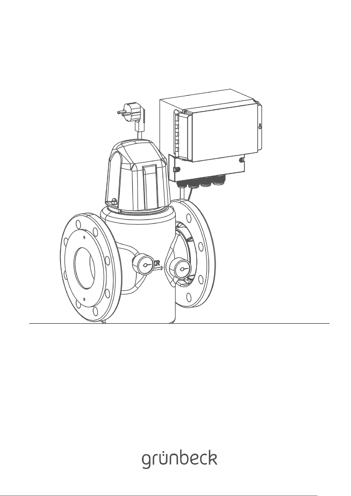
Filter | GENO-backwash filter MXA 1"- MXA DN 100
Operation manual
Page 2

General Contact
Germany
International Sales
Phone +49 9074 41-145
Technical Service
Phone +49 9074 41-333
Fax +49 9074 41-120
Availability
Monday to Thursday
7:00 am - 6:00 pm
Friday
7:00 am - 4:00 pm
Copyright
The manufacturer reserves the copyright to this operation manual. Without the written consent of
Grünbeck Wasseraufbereitung GmbH, no part of this manual may be reproduced in any way, nor
may any part be processed, duplicated or distributed using electronic systems.
Non-compliance with the aforementioned stipulations shall be subject to compensation for damages.
We reserve the right to technical modifications.
© by Grünbeck Wasseraufbereitung GmbH
Translation of the original operation manual
Edition of the operation manual: July 2019
Order no.: TD3-AM000en_014
Page 3
Table of contents
3 | 72
Table of contents
1 About this manual ..................................................... 4
1.1 Other applicable documents ...................................... 4
1.2 Target group .............................................................. 4
1.3 Storage of documents ................................................ 4
1.4 Symbols used ............................................................ 4
1.5 Typographical conventions ........................................ 5
1.6 Validity of the manual ................................................ 5
1.7 Type plate .................................................................. 6
2 Safety ......................................................................... 7
2.1 Safety measures ........................................................ 7
2.2 Technical safety instructions ...................................... 8
2.3 Regulations ................................................................ 8
2.4 Responsibilities of the specialist installer and/or
the specialist company .............................................. 8
2.5 Responsibilities of the owner/user ............................. 9
2.6 Product-specific safety instructions ........................... 9
2.7 Packaging, shipping and storage ............................... 9
3 Product description ................................................ 10
3.1 Intended use ............................................................ 10
3.2 Foreseeable misuse ................................................ 10
3.3 Product components ................................................ 11
3.4 Functional description .............................................. 12
3.5 Accessories ............................................................. 14
4 Installation ............................................................... 15
4.2 Requirements regarding the installation site ............ 17
4.3 Checking the scope of supply .................................. 18
4.4 Installing the product ................................................ 19
5 Control unit GENO-RS-tronic ................................. 28
5.1 Components of the control unit ................................ 28
5.2 Overview of display .................................................. 30
5.3 Navigating the control unit ....................................... 33
5.4 Menu structure ......................................................... 36
5.5 Programming levels ................................................. 36
6 Start-up .................................................................... 38
6.1 Preparations .............................................................38
6.2 Starting up the product .............................................39
6.3 Handing over the product to the owner/user ............39
7 Operation ..................................................................40
7.1 Information in the basic display ................................40
7.2 Setting parameters in the User level.........................41
7.3 Setting parameters in the Programming level ..........42
8 Cleaning, inspection, maintenance ........................46
8.1 Cleaning ...................................................................46
8.2 Intervals ....................................................................47
8.3 Inspection .................................................................47
8.4 Maintenance .............................................................48
8.5 Spare parts ...............................................................53
8.6 Wearing parts ...........................................................53
9 Troubleshooting .......................................................54
9.1 Display messages ....................................................54
9.2 Other malfunctions ...................................................57
9.3 Manually closing the filter’s suction nozzle ...............59
10 Disposal ....................................................................62
10.1 Packaging .................................................................62
10.2 Product .....................................................................62
11 Technical specifications .........................................63
11.1 Pressure loss curves ................................................65
12 Operation log ............................................................67
12.1 Start-up log ...............................................................67
12.2 Maintenance .............................................................68
EU Declaration of Conformity ..........................................69
Index ...................................................................................70
Page 4
About this manual
4 | 72
BA_TD3-AM001en_014_MXA.docx
1 About this manual
1.1 Other applicable documents
The following documents shall be considered as applicable documents for the GENO
backwash filter as well:
● For Grünbeck's technical service/authorised service company:
Technical service manual GENO-backwash filter MXA
Order no.: TD4-AM001en
● The manuals of all accessories used.
1.2 Target group
This manual is intended for specialist installers and owners/users.
1.3 Storage of documents
Keep this manual and all other applicable documents, so that they are available when
needed. Make sure that your specialist installer enters the proper start-up and annual
maintenance in chapter 12 of the operation log.
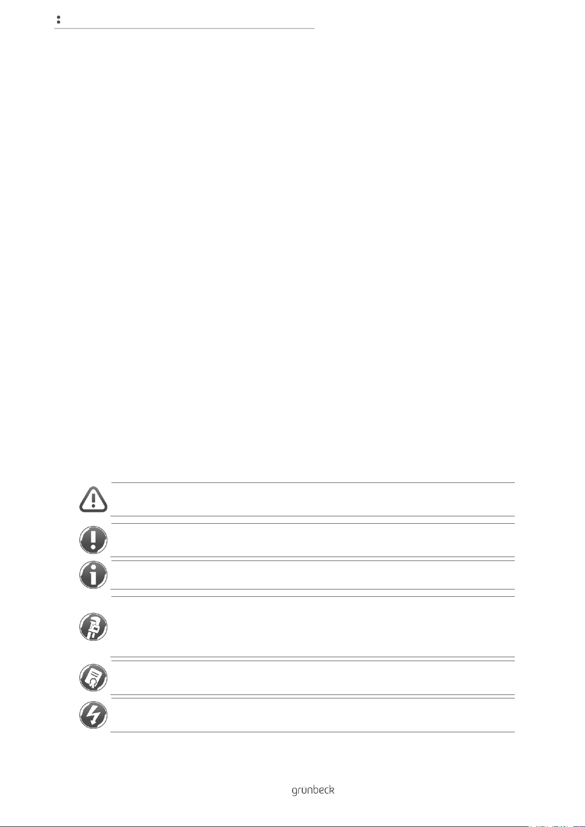
1.4 Symbols used
This symbol identifies instructions that you must comply with for your own personal safety
as well as to avoid damage to property.
This symbol identifies instructions that you must comply with in order to avoid damage to
property.
This symbol identifies important information about the product or its handling.
This symbol identifies work that may only be carried out by a specialist installer. In
Germany, the installation company must be registered in an installation directory of a water
supply company acc. to §12(2) AVB Wasser V (German Ordinance on General Conditions
for the Supply of Water).
This symbol identifies work that may only be carried out by Grünbeck's technical
service/authorised service company or by specialist installers trained by Grünbeck.
This symbol identifies work that may only be carried out by electronically trained personnel
according to the VDE guidelines or according to the guidelines of similar local institutions.
Page 5
About this manual
5 | 72
BA_TD3-AM001en_014_MXA.docx
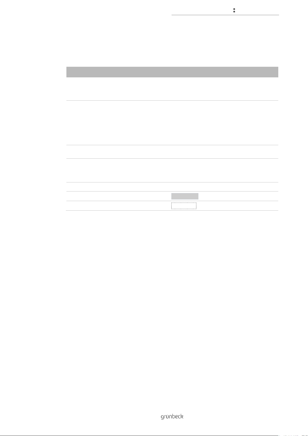
1.5 Typographical conventions
The following typographical conventions are used in this manual:
Designation
Depiction
Instruction
Single-step instruction or chronological
sequence of steps does not matter
► Action
Instruction
Multi-step instruction and chronological
sequence of steps is important
1. First action
a first step
b second step
2. Second action
Result following an instruction
» Result
Lists
● Listed item
• Listed sub-item
Menu paths
Status level>Menu level>Submenu
Display texts
Display text
Operating elements
Button/key
1.6 Validity of the manual
This manual applies to the following products:
● GENO-backwash filter MXA 1" (DN 25)
● GENO-backwash filter MXA 1¼" (DN 32)
● GENO- backwash filter MXA 1½ (DN 40)
● GENO-backwash filter MXA 2" (DN 50)
● GENO-backwash filter MXA DN 65
● GENO-backwash filter MXA DN 80
● GENO-backwash filter MXA DN 100
Page 6
About this manual
6 | 72
BA_TD3-AM001en_014_MXA.docx
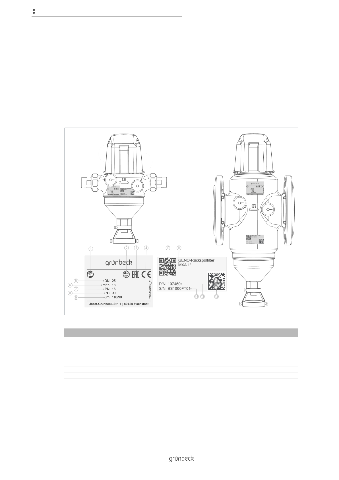
1.7 Type plate
The type plate is located on the front of the filter housing.
Please specify the data shown on the type plate in order to speed up the processing of your
inquiries or orders.
► Therefore, add the serial number in order to have the necessary data available at
all times.
Item
Designation
Item
Designation
1
Observe operation manual
2
DVGW test mark
3
EAC mark
4
CE mark
5
Nominal connection diameter
6
Nominal flow
7
Nominal pressure
8
Max. water temperature
9
Max./min. pore size
10
QR code
11
Product designation
12
Data matrix code
13
Order no.
14
Serial no.
● Product designation: GENO-backwash filter MXA_______
● Order number: 107 ______
● Serial no.: ________________
Page 7
Safety
7 | 72
BA_TD3-AM001en_014_MXA.docx
2 Safety
WARNING: Contamination of drinking water due to improper handling.
● Risk of infectious diseases.
► Have the installation, start-up and annual maintenance carried out by specialist
installers only.
2.1 Safety measures
● Carefully read this manual before operating your product.
● Install the product in a frost-free room. Otherwise, the system may suffer
irreparable damage. Water damage may occur as a result.
● Only use genuine spare parts for maintenance or repair. If unsuitable spare parts
are used, the warranty for your product will be void.
● Do not use any products which have a damaged mains cable. This can lead to
injuries due to electric shock. Have damaged mains cables replaced without delay.
● Keep your product permanently connected to the power and water supply.
● Comply with the hygiene instructions in chapter 8. Failure to comply can result in
microbiological contamination of your drinking water installation.
● Only have persons working on your product that have read and understood the
present manual and that are qualified to do such work due to their vocational
training.
● Only operate the product if all components are installed properly.
● Safety equipment must never be removed, bridged or otherwise tampered with.
● Observe the maintenance intervals (refer to chapter 8.2). Failure to comply can
result in microbiological contamination of your drinking water installation.
● This product can be used by children over 8 years of age and persons with limited
abilities or lack of experience if they are supervised or instructed in the safe use of
the product and understand the resulting hazards.
● Cleaning and maintenance must not be carried out by children.
● Keep the product away from children.
Page 8
Safety
8 | 72
BA_TD3-AM001en_014_MXA.docx
2.2 Technical safety instructions
This manual contains information and instructions that you must comply with for your own
personal safety as well as to avoid damage to property. The information and instructions are
highlighted by a warning triangle and have the following structure:
CAUTION: Type and source of danger.
● Possible consequences
► Preventive measures
The following signal words were defined subject to the degree of danger and may be used in
the present document:
● DANGER means that death or serious injury will result.
● WARNING means that death or serious injury may result.
● CAUTION means that minor bodily injuries may occur.
● NOTE (without warning triangle) means that damage to property may occur.
2.3 Regulations
When installing and starting up the system, amongst others, comply with the following
regulations and guidelines:
● Statutory regulations on environmental protection
● Provisions of the employers' liability insurance companies
● DIN EN 806 Specifications for installations inside buildings conveying water for
human consumption
● VDI 6023 Part 5 - 7 Specifications for installations inside buildings conveying water
for human consumption
● Low Voltage Directive 2014/35/EU, Appendix IV
2.4 Responsibilities of the specialist installer and/or the
specialist company
Comply with the following instructions to ensure the proper and safe functioning of the
product:
● Only perform activities described in this manual.
● Perform all activities in accordance with all applicable standards and regulations.
● Brief the owner/user on the function and operation of the product.
● Advise the owner/user of the maintenance of the product.
Page 9
Safety
9 | 72
BA_TD3-AM001en_014_MXA.docx
● Inform the owner/user about possible dangers that can arise during the operation
of the product.
● Fill in the operation log (refer to chapter 12).
2.5 Responsibilities of the owner/user
Comply with the following instructions to ensure the proper and safe functioning of the
product:
● Arrange for a specialist installer to carry out installation, start-up and maintenance.
● Have the product explained to you by the specialist installer.
● Only perform activities described in this manual.
● Do not carry out any activities that are explicitly designated for a specialist installer.
● Only use this product as intended.
● Make sure that the required inspection and maintenance work is carried out.
● Keep this manual.
2.6 Product-specific safety instructions
WARNING: If the intervals for inspection and backwash are not observed, the filter element
will become excessively polluted.
● Health risk due to contamination of the drinking water.
► Observe the intervals and recommendations for inspection and backwash of the
filter element.
2.7 Packaging, shipping and storage
Transport
► Transport the filters only in their original packaging.
Storage
► Protect the product from:
● Damp, moisture, environmental impacts such as wind, rain, snow, etc.
● Frost, direct sunlight, severe heat exposure
● Chemicals, dyes, solvents and their vapours
Page 10

Product description
10 | 72
BA_TD3-AM001en_014_MXA.docx
3 Product description
3.1 Intended use
● GENO-backwash filters MXA are designed for the filtration of drinking and
industrial water.
● The filters are suitable for the filtration of process, boiler feed, cooling and air
conditioning water – only in partial flow.
● The filters are suitable for water temperatures up to 90 ºC.
● The filters can be used in the pressure range.
● The filters are designed according to the stipulations of DIN EN 13443-1 and
DIN 19628 and are intended for installation into drinking water pipes according to
DIN EN 806-2 (installation immediately downstream of the water meter).
● The filters protect the water pipes and connected water-carrying system parts from
disturbances and corrosion damage due to undissolved impurities (particles), such
as rust particles, sand, etc.
3.2 Foreseeable misuse
● The filters cannot be used in the negative pressure range.
● The filters are not suitable for circulation water that has been treated with
chemicals.
● The filters are neither suitable for oils, greases, solvents, soaps and other
lubricating media, nor for the separation of water-soluble substances.
● Do not install the filters in vertical water pipes.
Page 11
Product description
11 | 72
BA_TD3-AM001en_014_MXA.docx
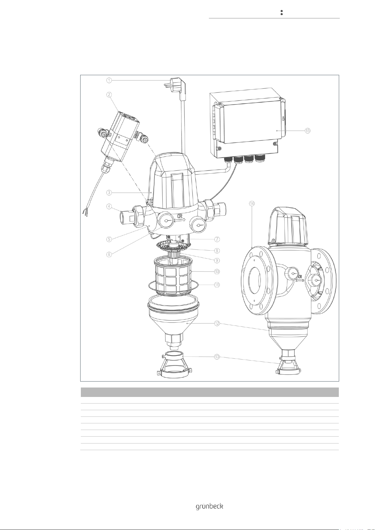
3.3 Product components
Item
Designation
Item
Designation
1
Shock-proof plug, 1.5 m cable
2
Differential pressure sensor
3
Cover
4
Water meter screw connection
5
Filter housing
6
Pressure gauge
7
Brush
8
Sieve bottom
9
Suction nozzle
10
Filter element
11
Gasket
12
Filter funnel
13
Backwash water connection
14
Flange connection
15
Control unit GENO-RS-tronic
Page 12
Product description
12 | 72
BA_TD3-AM001en_014_MXA.docx
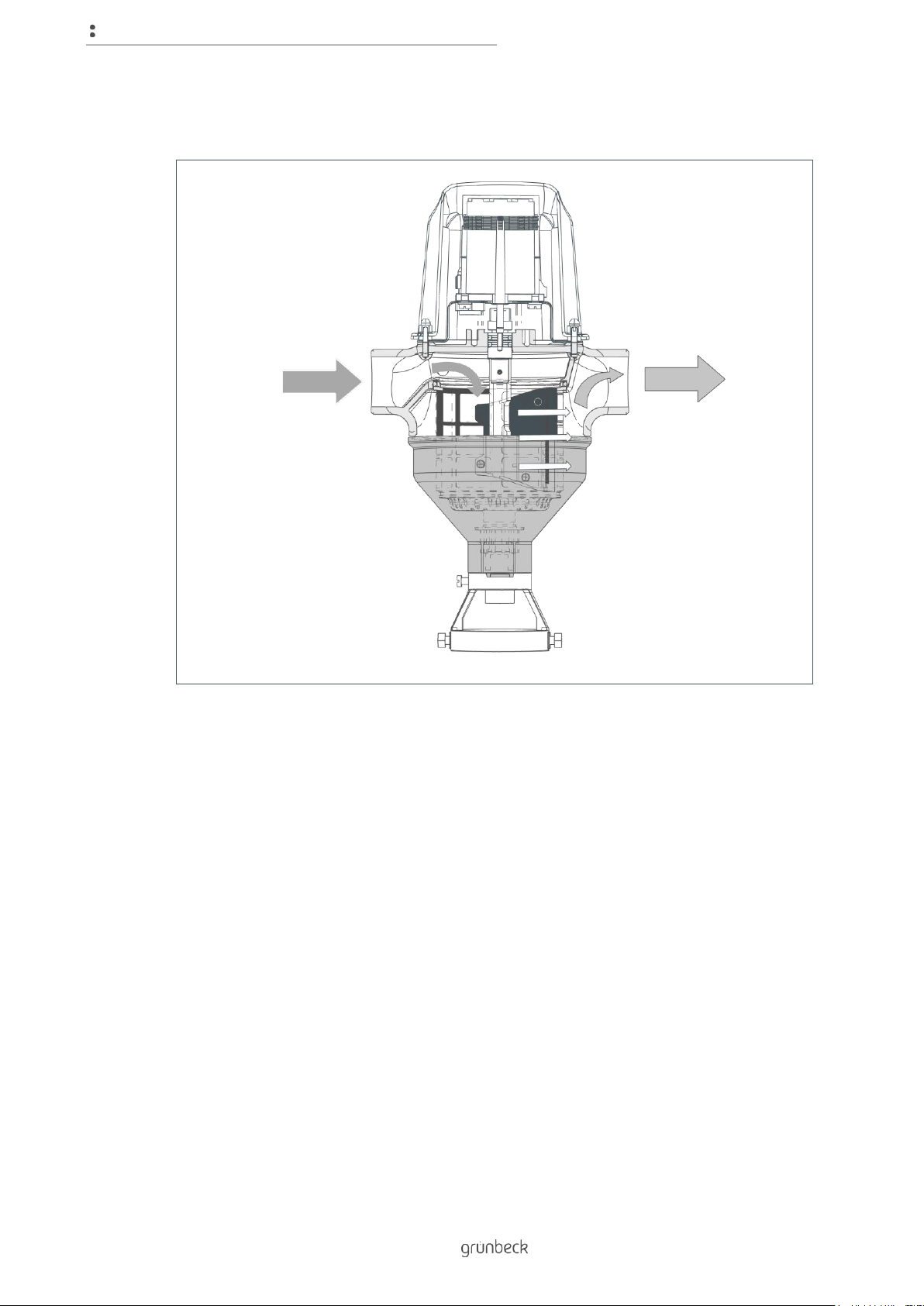
3.4 Functional description
The unfiltered raw water flows into the filter from the inlet side and then from the inside out
through the filter element and to the pure water outlet.
Thus, foreign particles of a size > 100 µm are retained.
Depending on their size and weight, the foreign particles stick to the filter element or they fall
straight down into the filter funnel.
The backwash process is activated by the GENO-RS-tronic control unit and carried out by
the drive unit on the filter head. The lower suction nozzle is lifted and the drain outlet is open.
During the rotating motion, the brush brushes over the filter surface of the filter element. The
filter element is cleaned.
The impurities are removed by the brush and the suction nozzle sucks them into the drain
outlet.
Page 13

Product description
13 | 72
BA_TD3-AM001en_014_MXA.docx
3.4.1 Backwash with the GENO-RS-tronic control unit
The GENO-RS-tronic control unit activates time and differential pressure controlled
backwash processes.
Apart from a time interval for the activation of a backwash, an off-period during which no
backwash processes may take place can also be defined.
An actuator opens the backwash water outlet. Initially, in clocked operation and then with
continuous rotation.
The rotation triggers the contact of a microswitch via a cam disc. The microswitch sends
pulses to the control unit. After several pulses, the control unit reverses the direction of
rotation and closes the backwash water outlet.
If the rotary motion is blocked by dirt or wear and tear, the control unit detects this and
responds automatically.
If the control unit cannot resolve the issue independently, a corresponding error message is
displayed (refer to chapter 9).
The control unit features a voltage-free fault signal contact and a voltage-free contact for
remote monitoring. A backwash in progress is signalled via the voltage-free contact.
The control unit monitors the number of backwashes. It provides - sometimes in conjunction
with a timed maintenance interval - information on the remaining number of backwashes in
the current maintenance interval via a bar graph in the display.
Page 14
Product description
14 | 72
BA_TD3-AM001en_014_MXA.docx
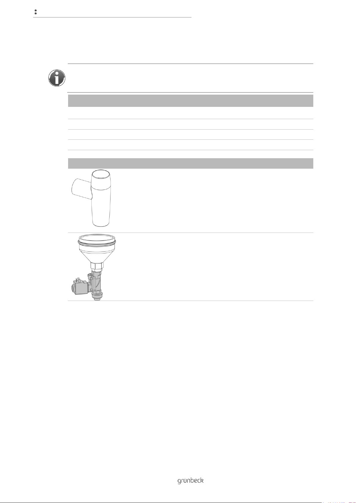
3.5 Accessories
You can retrofit your product with additional accessories. Please contact your local
Grünbeck representative or Grünbeck’s headquarters in Hoechstaedt for more details (refer
to www.gruenbeck.com).
Designation
Order no.
1" / 1¼"
1½" / 2" / DN 65
DN 80 / DN 100
50 µm filter element
107 052
107 053
107 054
200 µm filter element
107 072
107 073
107 074
500 µm filter element
107 082
107 083
107 084
Illustration
Product
Order no.
Drain connection DN 50 acc. to DIN EN 1717
with integrated siphon
188 875
Safety valve for MXA
GENO-RS-tronic-controlled, normally closed
solenoid valve.
Is installed at the backwash water outlet and
prevents inadmissible water leakage during a
backwash process, e.g. in case of a power
failure.
107 850
Page 15

Installation
15 | 72
BA_TD3-AM001en_014_MXA.docx
4 Installation
The installation of a filter represents a major intervention into the drinking water system and
may only be performed by a specialist installer.
In accordance with DIN EN 806-2 and DIN EN 1717, the product is installed in the water pipe
downstream of the water meter and upstream of distribution pipes or the systems to be
protected.
NOTE: Significant temperature differences occurring when the product is moved from one
location to another can lead to moisture forming on electronic components within the
control unit.
● Possible malfunction of the control unit during initial start-up.
► We recommend unpacking the product prior to installation and allowing it to rest
at the installation site for 1 hour without being used.
» Possible moisture formation on electronic components inside the control unit can
dry off.
Page 16
Installation
16 | 72
BA_TD3-AM001en_014_MXA.docx
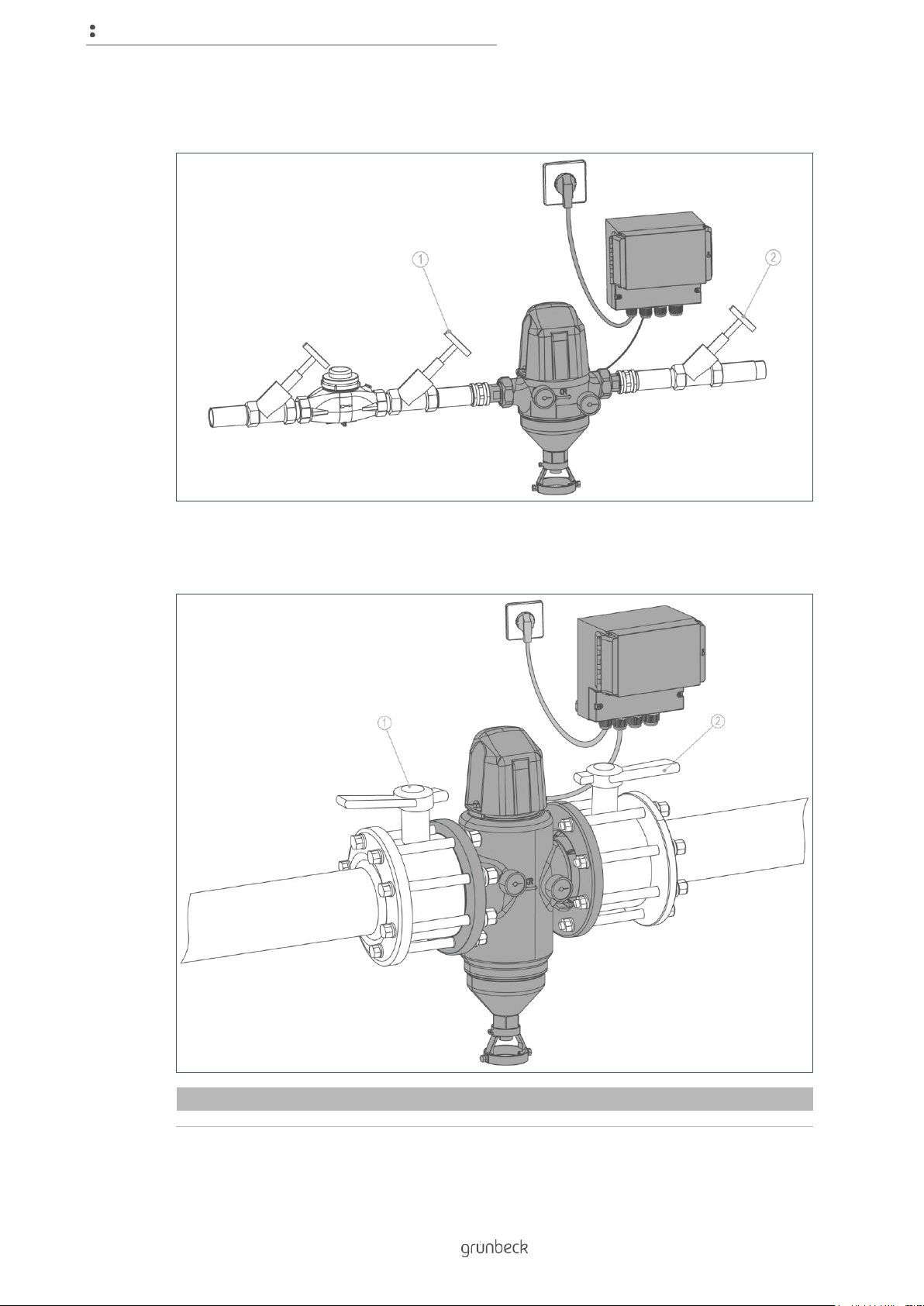
GENO-backwash filter MXA with screw connections
GENO-backwash filter MXA with flange connections
Item
Designation
Item
Designation
1
Inlet shut-off valve
2
Outlet shut-off valve
Page 17
Installation
17 | 72
BA_TD3-AM001en_014_MXA.docx
4.2 Requirements regarding the installation site
Observe local installation directives, general guidelines and technical specifications.
● The installation site must be frost-proof and ensure the filter's protection from
chemicals, dyes, solvents, vapours and direct sunlight.
● A drain connection (DN 50) must be available to discharge the backwash water.
● The installation room must provide a floor drain. If no floor drain is available, an
appropriate safety device must be installed in order to prevent water damage. We
recommend using a protectliQ:A.
● The installation site must be easily accessible for maintenance purposes.
● A shock-proof socket is required within a distance of approx. 1.2 m of the system.
NOTE: Power failure during the backwash process.
● Backwash will not be completed if the electrical power supply is interrupted.
● The backwash process continues until it is terminated manually.
► Do not connect the socket with light and heating switches.
Page 18
Installation
18 | 72
BA_TD3-AM001en_014_MXA.docx
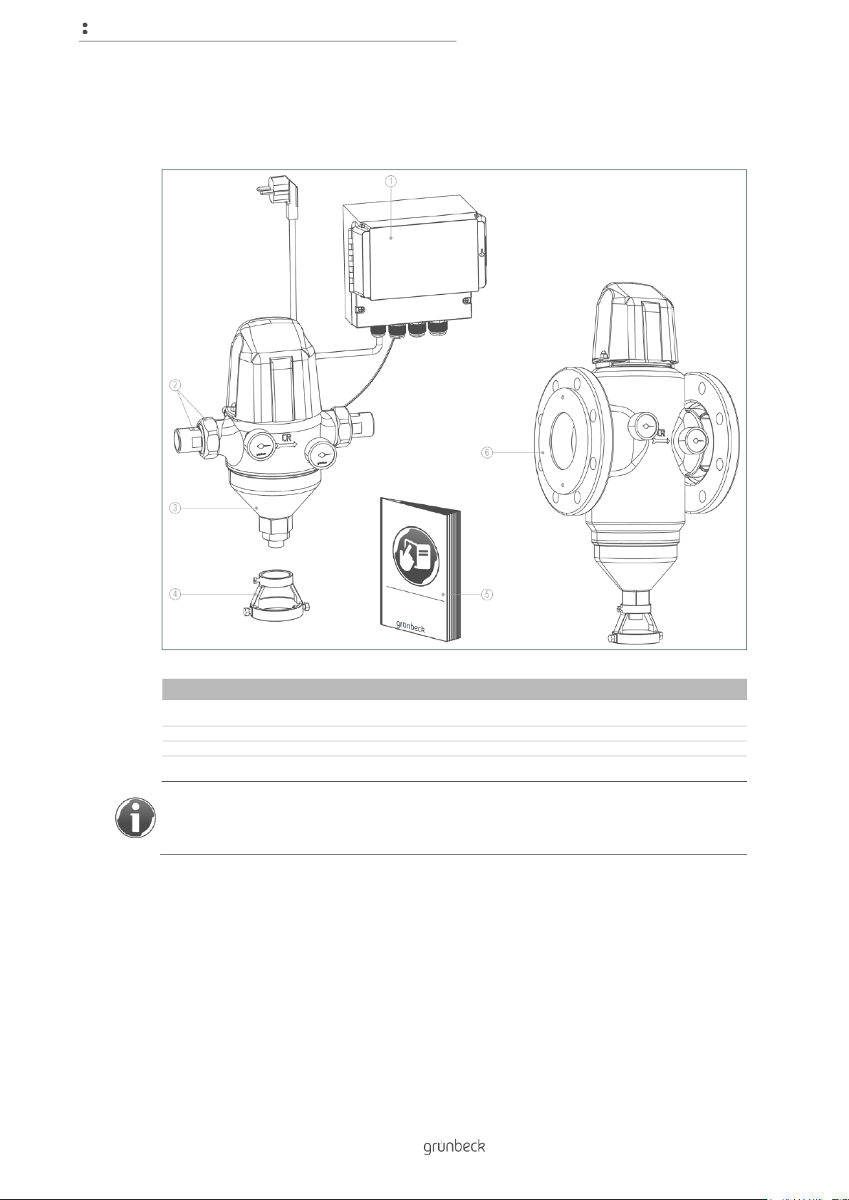
4.3 Checking the scope of supply
Item
Designation
Item
Designation
1
Control unit GENO-RS-tronic
2
Water meter screw connection with gasket,
union nut
3
Filter with screw connections
4
Backwash water connection
5
Operation manual
6
Filter with flange connections
The filter is available with screw connections for sizes: 1" (DN 25), 1¼" (DN 32),
1½" (DN 40), 2" (DN 50)
The filter is available with flange connections for sizes: DN 65, DN 80, DN 100
► Check the scope of supply for completeness and possible damage.
Page 19
Installation
19 | 72
BA_TD3-AM001en_014_MXA.docx
4.4 Installing the product
Only install the GENO-backwash filter MXA horizontally and without mechanical stress.
Please note the following points before installation:
● Installation only possible in horizontal position
● Free outlet and discharge of the backwash water without backpressure
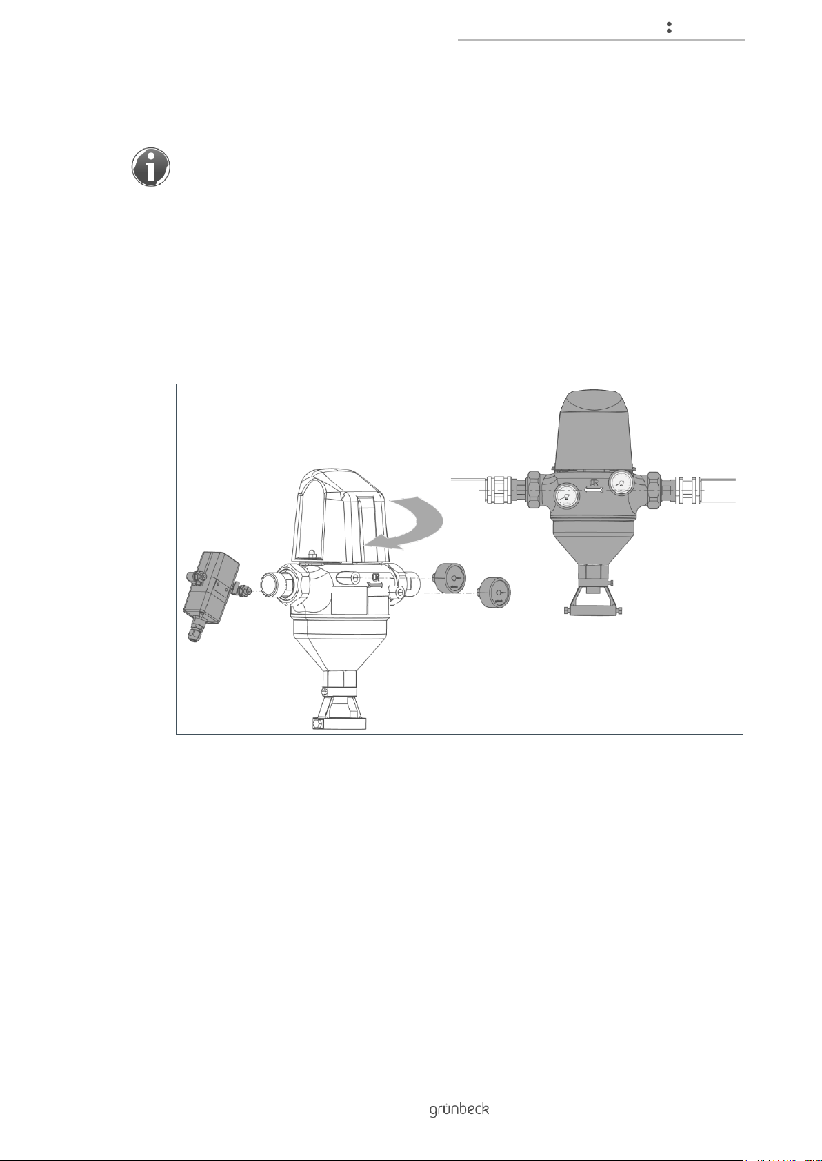
4.4.1 Changing the direction of flow
► Check the flow direction given on site.
► If necessary, remount the filter as follows:
1. Unscrew the differential pressure sensor and the pressure gauges.
2. Rotate the filter by 180°.
3. Mount the differential pressure sensor and the pressure gauges.
» The filter has been modified for flow direction to the left.
Page 20

Installation
20 | 72
BA_TD3-AM001en_014_MXA.docx
4.4.2 Installing the GENO-backwash filter MXA with screw connections
1. Install the pipe fitting into the pipe (the installation dimension must be:
190 mm for sizes 1", 1¼" and 206 mm for sizes 1½", 2").
2. Position the filter (note the marking for the flow direction on the filter).
3. Tighten the filter at the pipe fittings using an open-ended wrench without applying
mechanical stress
» The filter is mounted.
Page 21
Installation
21 | 72
BA_TD3-AM001en_014_MXA.docx
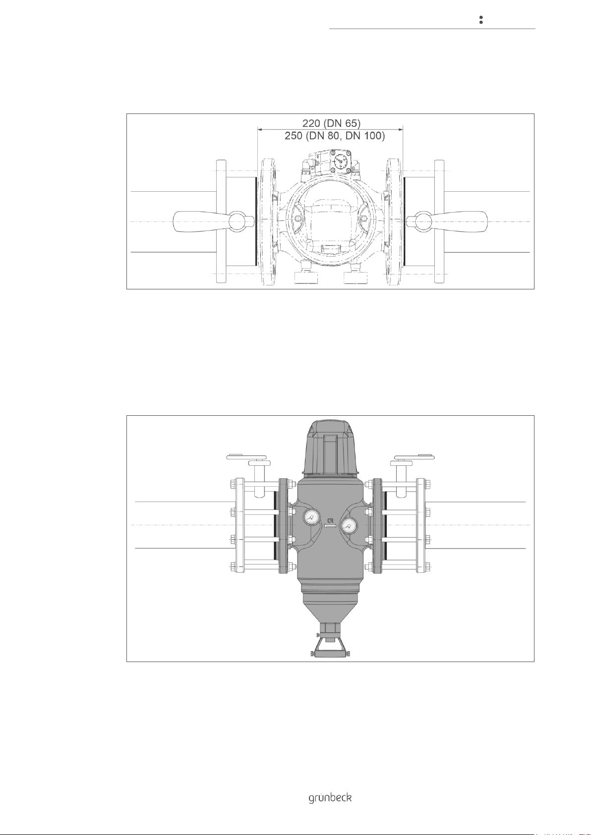
4.4.3 Installing the GENO-backwash filter MXA with flange connection
1. Prepare the pipe with flange connection in accordance with DIN EN 1092-1 (the
distance between the two gaskets must be: 220 mm for DN 65 and 250 mm for
DN 80 and DN 100).
2. Position the filter (note the marking for the flow direction on the filter).
3. Tighten the filter at the flanges by means of the screw connections without applying
mechanical stress.
» The filter is mounted.
Page 22
Installation
22 | 72
BA_TD3-AM001en_014_MXA.docx
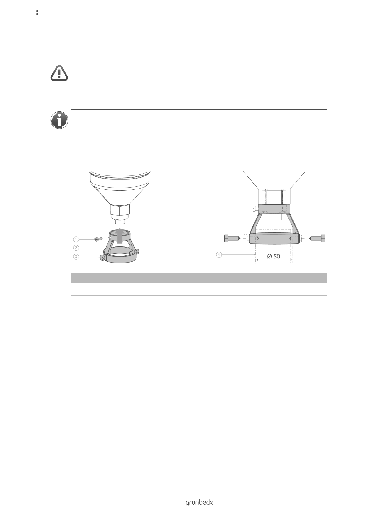
4.4.4 Installing the backwash water connection
CAUTION: Splashing hot water at the drain outlet during backwash.
● Danger of scalding in case of hot water filtration without waste water pipe.
► For hot water filtration, install a fixed waste water pipe at the drain connection.
If it is not possible to install a waste water pipe, the backwash water can be collected in a
bucket/container.
► Install a waste water pipe (not included in the scope of supply) at the pre-installed
drain connection with free outlet.
Item
Designation
Item
Designation
1
Clamping screw
2
Backwash water connection
3
Pointed screw
4
Waste water pipe (HT pipe DN 50)
1. Push the backwash water connection onto the collar of the filter funnel.
2. Fix the backwash water connection by means of the clamping screw.
3. Push the waste water pipe into the backwash water connection as far as it will go.
4. Fix the waste water pipe with the pointed screws.
Page 23

Installation
23 | 72
BA_TD3-AM001en_014_MXA.docx
5. Install a waste water pipe towards the drain connection.
» The backwash water connection is installed.
The drain connection is available as an option (refer to Accessories, chapter 3.5).
To install the drain connection, follow the mounting instructions TD5-BS002.
Page 24

Installation
24 | 72
BA_TD3-AM001en_014_MXA.docx
4.4.5 Electrical installation
DANGER! Live components!
● Risk of electric shock when working on the electrical system.
► Make sure that the mains voltage is disconnected and that the plug is unplugged.
► Do not connect to mains until the connection work has been completed and the
control unit is closed.
The electrical installation may only be carried out by a skilled craftsman.
► Unscrew the cover of the connections at the control unit.
Page 25

Installation
25 | 72
BA_TD3-AM001en_014_MXA.docx
Fastening the control unit
The control unit must not be installed in the immediate vicinity of heat sources with high
radiation temperatures.
► Fasten the control unit on the wall.
NOTE: Securely fasten the control unit.
● Precarious and unsound fastening can cause the control unit to crash.
► Prior to fastening the control unit, check the wall type present.
► Select fasteners on site which are suitable for the respective wall type.
► Position the control unit while taking the length of the connecting cable into
consideration - connecting cables must not be extended.
► Fix the control unit with three screws.
Page 26

Installation
26 | 72
BA_TD3-AM001en_014_MXA.docx
Wiring diagram of the control unit
Wiring diagram of GENO-backwash filter MXA
Item
Designation
Item
Designation
A
Safety solenoid valve
K
Connecting line to filter
B
Backwash valve Open
L
Brown
C
Backwash valve Closed
M
Motor, 24 V~
D
Cam N Blue E Ext. input
O
Black
F
Illuminated LED: Voltage supply, cam-operated
switch, programmable input and differential pressure
switch OK
P
Safety device solenoid valve, 24 V ~,
order no. 107 850
G
Differential pressure switch
Q
Backwash signal
H
Do not connect wire 3
R
Collective fault signal active, contact rating:
250 VAC/3A each
I
Programmable input
M
Mains 230 VAC/50 Hz
J
Cam-operated switch
T
System fuse, T2A
General electrical installation
► Make the electrical connection according to the wiring diagram.
1. Connect the differential pressure cable to the control unit.
2. Connect the connecting lines to the filter with the control unit.
3. Connect additional accessories according to the wiring diagram.
4. Screw on the cover after the connection has been completed.
» The general electrical wiring is completed.
Connection to mains voltage will only take place during start-up (refer to chapter 6).
Page 27

Installation
27 | 72
BA_TD3-AM001en_014_MXA.docx
4.4.6 Additional inputs and outputs
Activation of backwash at external input
In addition to the general electrical wiring, you can install the control unit for external
activation of the backwash.
► Connect the connecting line at the external input E, terminals 17 and 18.
This control unit input is designed for wiring with a voltage-free contact.
If it is closed for more than 1 second, a backwash will be carried out.
The prerequisites for the activation of a backwash at the external input are:
● No backwash active
● No error Er 3 or Er 5 active
● No backwash lock active
Backwash lock at external input
As an alternative, the input can be used for an external backwash lock (refer to
chapter 5.5.1, Parameter “d”).
Combined operation of two GENO-backwash filters MXA
By means of these two inputs and outputs, two control units can be operated in combination,
so that the two filters are not backwashed at the same time.
To do so, the external input is programmed for external backwash lock on both control units
and connected to the signal output backwash of the respective other control unit:
Filter 1
Filter 2
Terminal 17
to
Terminal 8
Terminal 18
to
Terminal 9
Terminal 8
to
Terminal 17
Terminal 9
to
Terminal 18
The collective fault signal is designed as active, voltage-free change-over contact.
Page 28

Control unit GENO-RS-tronic
28 | 72
BA_TD3-AM001en_014_MXA.docx
5 Control unit GENO-RS-tronic
5.1 Components of the control unit
Item
Designation
Item
Designation
1
Shock-proof plug, 1.5 m cable
2
Cover
3
Operating / Menu level
4
Release button
5
Connection level
NOTE: Incorrect setting/operation of the control unit
● Dangerous operating conditions/functional impairments may occur health/personal/property damage possible
► Only make the settings described in this chapter.
► Have additional settings made by specialist installers or trained personnel only -
refer to the technical service manual “GENO-RS-tronic”.
Page 29

Control unit GENO-RS-tronic
29 | 72
BA_TD3-AM001en_014_MXA.docx
5.1.1 Releasing a backwash
With the GENO-RS-tronic, a backwash can be activated in:
1. Automatic release by time interval
● The time interval is adjustable from 1 hour - 99 days.
● The time interval is generally active.
● From an interval period >= 1 day, the start time can be programmed as well.
● An off-period during which no backwash will be released can be activated.
● Automatic backwash before and after the off-period.
2. Automatic activation after a differential pressure is reached
● The differential pressure sensor detects the differential pressure between the raw
water side and the pure water side.
● The differential pressure sensor triggers a backwash when approximately 0.4 bar is
exceeded. Default setting = 0.4 bar; adjustable from 0.16 – 1.6 bar.
● The differential pressure evaluation can be deactivated.
3. Activation by external signal
The backwash can be triggered by means of an external voltage-free contact.
If the contact is closed for more than 1 second, a backwash will be carried out.
Prerequisites for activation via the external contact are:
• No backwash lock is active
• No backwash is active
• No error Er 3 or Er 5 is present
The input can be reprogrammed for an external backwash lock.
4. Manual activation
The backwash can be activated manually by way of the button on the control unit (refer
to chapter 7.2.2). No backwash lock must be active. The basic display (time) must be
indicated.
Behaviour of the backwash filter if there is a power failure
From software version V3.2 on, the time is retained for a maximum of 180 min in the event of
a power failure. The number of the software version can be retrieved via Code level “999”
(refer to chapter 5.5.2).
If a power failure interrupts the backwash process for a maximum of°180°min, it will be
terminated correctly afterwards.
Page 30

Control unit GENO-RS-tronic
30 | 72
BA_TD3-AM001en_014_MXA.docx
5.2 Overview of display
Item
Designation
Item
Designation
1
Display
2
Connection data of the control unit
3
Button I for information
4
Button R for backwash
5
Button P for program
6
Explanation of manual backwash
7
Explanation of symbols displayed
Page 31

Control unit GENO-RS-tronic
31 | 72
BA_TD3-AM001en_014_MXA.docx
5.2.1 Display indication
First line
Illustration
Explanation
Wrench
• Displayed with error messages
• If the maintenance interval has elapsed or when more backwash
processes were carried out per maintenance interval than permitted.
Clock
Indicates an interval-controlled backwash:
• Statically - when the interval-controlled backwash is active
• Flashing - when an interval-controlled backwash is in progress
• Switched off - when a backwash lock is active
Differential pressure
Indicates a differential pressure controlled backwash:
• Statically - when the differential pressure evaluation is activated
• Flashing - when a backwash triggered by differential pressure is in
progress
• Switched off - when a backwash lock is active
External trigger active
Indicates a backwash triggered by an external control signal:
• Statically - when the programmable input is set for activation of an
external backwash
• Flashing - when a backwash triggered by the external signal is in
progress
• Switched off - when a backwash lock is active
Second line
Illustration
Explanation
Unit
Indicates the unit of the adjacent numerical value:
● Seconds
● Minutes
● Hours
● Days
Page 32

Control unit GENO-RS-tronic
32 | 72
BA_TD3-AM001en_014_MXA.docx
Second line
Standard operation
● Indicates the time (basic display)
Information menu level
● Indicates the operating parameters
User menu level
● Indicates the numerical value of the parameter in the menu
• Open parameters are flashing
Parameter number (small figure)
● In all menus, indicates the number of the parameter in the
current menu level
Additionally, and depending on the situation:
• “H” flashes during manual backwash and backwash after
acknowledgement of an error
• “A” flashes during automatic backwash 5 minutes before and at the
end of an off-period
• “E” flashes if the programmable input is set as backwash lock and the
external signal is present
• “c” flashes if the filter is moved to the “CLOSED” position after the
system voltage has been switched on
• “C” is displayed statically if a programming level is to be opened and
the code no. is displayed
Third line
Illustration
Explanation
Maintenance display
Indicates the lesser of the two values by percentage:
• Remaining days of the current maintenance interval
• Remaining number of backwash processes in the current
maintenance interval
Page 33

Control unit GENO-RS-tronic
33 | 72
BA_TD3-AM001en_014_MXA.docx
5.3 Navigating the control unit
► Press the release button on the side.
» The cover of the control unit is unlocked and can be opened.
5.3.1 Buttons
Illustration
Designation
Function
Program
Button P
In standard mode:
● Switches to User menu level.
In the User menu level:
● Opens parameters
● Saves the settings and closes parameters
Backwash
Button R
In standard mode:
● Starts the manual backwash
In the User menu level:
● Switches to previous parameter
● Decreases numerical values
During start-up:
● Closes the filter
Info
Button I
In standard mode:
● Calls up the Info level
● Switches the display to the next position
In the User menu level:
● Switches to the next parameter
● Increases numerical values
Page 34

Control unit GENO-RS-tronic
34 | 72
BA_TD3-AM001en_014_MXA.docx
5.3.2 Selecting menu levels
Objective
Step
Status level
► Press the buttons and at the same time.
Information level
► Press the button in the status level 1x - 6x, rotating
through the display and back to the basic display.
User menu level
► Press the button in the status level for more than
2.5 s.
Programming menu
level
► Press the buttons and in the status level at
the same time for more than 1 s.
» The display switches from the time to three flashing
digits “000” and the parameter no. changes to “C”.
1. Press the or the button to select Code 113.
2. Press the button to confirm your selection.
Menu level Software
Version
► Press the and the button in the status level
at the same time for more than 1 s.
» The display switches from the time to three flashing
digits “000” and the parameter no. changes to “C”.
1. Press the or the button to select Code 999.
2. Press the button to confirm your selection.
Page 35

Control unit GENO-RS-tronic
35 | 72
BA_TD3-AM001en_014_MXA.docx
5.3.3 Setting the parameters
Objective
Step
Selecting
parameters
In every menu level, the button switches to the next
parameter and the button switches to the previous parameter.
Opening
parameters
When the desired parameter is displayed:
► Press the button.
» The value of the parameter flashes.
Changing
parameters
When the open parameter flashes:
► Press the button for lower and the button for
higher values.
Closing parameters
without saving
If you want to exit the setting of the open parameter without making
any changes:
► Press the and the button at the same time.
» The parameter will be closed, and the unchanged value is
displayed continuously.
Saving parameters
When the right value flashes in the display:
► Press the button to save the value.
» The parameter will be closed, and the set value is
displayed continuously.
Exiting the
menu level
If you have made the desired settings:
► Press the and the button at the same time.
» The display shows the basic display (time) in the status
level.
Automatic return to
the basic display
The system also returns to the basic display if no entry is made for
more than 1 minute.
» Entries which had not been saved are lost.
Page 36

Control unit GENO-RS-tronic
36 | 72
BA_TD3-AM001en_014_MXA.docx
5.4 Menu structure
Menu level
Menu items
Values/settings
Status level
Acknowledgement of
malfunctions
Press one of the three buttons.
Manual backwash
Press the button for more than 5 s
Select the menu
level
Refer to chapter 5.3.2
Information
1
Current configuration of the backwash.
2
Active backwash interval, [hh:mm]
3
Status of backwash lock
4
Start time of backwash lock, when active,
[hh:mm]
5
Current configuration of microswitch
6
Return to basic display
User
Set the time
Hours and minutes separately, [hh:mm]
Programming /
Code-protected
levels
For settings and displays (refer to chapter 5.5).
5.5 Programming levels
5.5.1 User programming level via Code 113
Status level>Code-protected level 113
Parameters
Meaning
Factory
settings
Setting range
0
Evaluation of the
differential
pressure signal
The GENO-RS-tronic utilises the differential
pressure switch to detect independently
when a backwash is required
1
0 = Differential pressure signal is not
evaluated
1 = Differential pressure signal is
evaluated
1
Backwash
interval
Time after which a backwash takes place
automatically
30 d
1 – 23 h (hours), here, a backwash
always takes place at the full hour
1 – 99 d (days), here, the time can be
programmed in the parameters that
follow as well
2
Start time of the
intervalcontrolled
backwash
(hours)
When the backwash interval, parameter “1”,
is set in range 1 - 99 d
01:
00: - 23:
3
Start time of the
intervalcontrolled
backwash
(minutes)
When the backwash interval, parameter “1”,
is set in range 1 - 99 d
:00
:00 -:59
4
Activation of a
timed backwash
lock
The timed backwash lock can be used to
suppress any backwash for a programmable
period of time
0
0 = Timed backwash lock deactivated
1 = Timed backwash lock active
Page 37

Control unit GENO-RS-tronic
37 | 72
BA_TD3-AM001en_014_MXA.docx
If the backwash lock is activated, a backwash is performed automatically 5 min before the
start and after the end of the backwash lock.
A minimum of 1 hour must be scheduled between the start and the end of a backwash lock.
The interval-controlled backwash must be scheduled at a time outside of an active
backwash lock.
Parameters
Meaning
Factory
settings
Setting range
5
Start time of the
timed backwash
lock (hours)
If the timed backwash lock, parameter 4,
is activated
01:
00: - 23:
6
Start time of the
timed backwash
lock (minutes)
If the timed backwash lock, parameter 4,
is activated
:00
:00 -:59
7
End time of the
timed backwash
lock (hours)
If the timed backwash lock, parameter 4,
is activated
01:
00: - 23:
8
End time of the
timed backwash
lock (minutes)
If the timed backwash lock, parameter 4,
is activated
:00
:00 -:59
9
Maintenance
responsibility
Maintenance work must be carried out by
either the owner/user or Grünbeck's
technical service/authorised service
company
1
0 = Maintenance work is carried out
by the owner/user
1 = Maintenance work is carried out
by Grünbeck's technical
service/authorised service company
A
Acknowledgement
of maintenance
The owner/user notifies the
GENO-RS-tronic that maintenance was
carried out
0
0 = Basic mode
1 = Programming to perform the
function
b
Operating mode of
GENO-RS-tronic
Operation of the control unit on a
Grünbeck-backwash filter of model series
MXA or MSA.
Major differences between the two
operating modes: In case of MXA, the
rotation is monitored via microswitch
pulses; direction of rotation during
backwash
0
0 = MXA
1 = MSA
Only change the factory settings of the following parameter “C” if special motors or special
gear boxes are used.
Parameters
Meaning
Factory
settings
Setting range
C
Gearing
MXA: Gearbox output speed
MXA:
8 min-1
MXA: 1.0 - 15.0 min-1
MSA: Gear ratio
MSA:
46:1
MSA: 31:1, 46:1, 62:1
d
Programmable
input
For wiring and application refer to chapter
4.4.6.
0
0 = external activation of backwash
1 = external backwash lock
5.5.2 Software version via Code 999
Status level>Code-protected level 999
Parameters
Meaning
Factory
settings
Setting range
C
Software version
Software version of control unit
0
-
Page 38

Start-up
38 | 72
BA_TD3-AM001en_014_MXA.docx
6 Start-up
6.1 Preparations
NOTE: Upon delivery, the drain outlet of the GENO-backwash filters MXA is open.
► Close the open drain outlet for 1.5 min:
1. Press and hold the button.
2. Plug the mains plug into the socket.
3. Release the button.
NOTE: Faulty connection/installation
● Filter is not closing, or the green lamp above terminal 20 only lights up dimly or
not at all.
► Disconnect the mains plug and check the installation of the product.
Page 39

Start-up
39 | 72
BA_TD3-AM001en_014_MXA.docx
6.2 Starting up the product
► Carry out the following steps after installation and after every maintenance.
1. Set the time (refer to chapter 7.2.1).
2. Set other operating parameters, if necessary (refer to chapter 7.2).
3. Open the shut-off valves.
4. Open the closest water withdrawal point downstream of the filter to the maximum.
5. Apply the maximum operating pressure.
» The filter is vented.
6. Check the filter for tightness.
7. Carry out a backwash.
» The filter is in operation.
6.3 Handing over the product to the owner/user
► Explain to the owner/user how the product works.
► Use the manual to brief the owner/user and answer any questions.
► Inform the owner/user about the need for inspections and maintenance.
► Hand over all documents to the owner/user for keeping.
► Enter the initial start-up in the operation log (refer to chapter 12.1).
Page 40

Operation
40 | 72
BA_TD3-AM001en_014_MXA.docx
7 Operation
7.1 Information in the basic display
Status level
The display continuously gives information on the operating state of the system.
Indicating parameters in the basic display:
● Functions that are activated to trigger a backwash.
● Function by which the current backwash was triggered.
● Whether a backwash lock is active.
● Time until the next maintenance and/or the remaining number of backwash
processes until the next maintenance.
● Time stored.
7.1.1 Retrieving information
Status level>Information level
Press the button to call up information about other parameters:
Button
pressed
Indication
Explanation
1 x
0
Backwash function with differential pressure signal OFF
(deactivated)
1
Backwash function with differential pressure signal ON
(active)
2x
± XX %
Active interval for backwashing in hours or days
3 x
0
Backwash lock function deactivated
1
Backwash lock function active
Page 41

Operation
41 | 72
BA_TD3-AM001en_014_MXA.docx
Button
pressed
Indication
Explanation
4x
-
Go to 5x if backwash lock function is deactivated
XX:XX
Start time of backwash lock
YY:YY
End time of backwash lock
5x
XX:YY
Number of microswitch pulses during the last backwash
process. The displayed value is only updated during the
ongoing backwash
XX
Upon opening, factory setting 36
YY:
Upon closing, factory setting 34...40
6x
XX:XX
Display is reset to basic display (time)
7.2 Setting parameters in the User level
7.2.1 Setting the current time
Status level>User level
► Set the current hour and minutes:
1. Press the button to open the parameter for the hours.
» The display for hours flashes.
2. Press the or the button to set desired value.
3. Press the button to save the setting.
» The current hour is saved.
Page 42

Operation
42 | 72
BA_TD3-AM001en_014_MXA.docx
4. Press the button to switch to the display for minutes.
5. Press the button to open the parameter for the minutes.
» The display for minutes flashes.
6. Press the or the button to set desired value.
7. Press the button to save the setting.
» The current time is set.
7.2.2 Starting a backwash manually
Status level
► Press and hold the button for more than 5 s.
» A manual backwash is carried out.
7.3 Setting parameters in the Programming level
Settings deviating from the factory settings may only be carried out by trained technical
service personnel.
Status level>Programming level
Page 43

Operation
43 | 72
BA_TD3-AM001en_014_MXA.docx
7.3.1 Entering the Code
► Press the buttons and in the status level for more than 1 s.
» The display switches from the time to the three flashing digits “000” and the
parameter no. switches to “C”.
1. Press the or the button to select code 113.
6. Press the button to confirm the selection.
7.3.2 Evaluation of the differential pressure signal
7. Press the button to switch to the evaluation of the differential pressure signal.
Page 44

Operation
44 | 72
BA_TD3-AM001en_014_MXA.docx
7.3.3 Setting the backwash interval
The example below shows you how to work in the programming level/code-protected level.
The interval-controlled backwash is always active and set to 30 d in the factory setting.
You can choose between two configurations:
Period
Range
Explanation
Hours
[h]
1 - 23
Backwash at the full hour every h
hours
Days + Hours
[d] + [h]
(1 – 99) + (1 – 23)
Backwash every d days and, in the
next menu, h hours.
Setting the backwash interval:
1. Press the button to switch to parameter „1“.
» In the factory setting, the following is displayed:
• “1” for the selected parameter
• The value “30” for the days set
• The unit “d” for days
2. Press the button to open the parameter.
» The value of the parameter flashes.
3. Press the or the button to set the desired value of the parameter.
4. Press the button to save the value.
» The value of the parameter stops flashing.
» The days are set.
5. Press the button to switch to the display of the value for the hours.
6. Press the button to open the parameter for the hours.
Page 45

Operation
45 | 72
BA_TD3-AM001en_014_MXA.docx
7. Press the or the button to set the desired value of the parameter.
8. Press the button to save the value.
» The value of the parameter stops flashing.
» The hours are set.
► Press the and the button at the same time to return to the status level
(basic display).
Programming further parameters is done in an analogous manner.
Page 46

Cleaning, inspection, maintenance
46 | 72
BA_TD3-AM001en_014_MXA.docx
8 Cleaning, inspection, maintenance
WARNING: Danger of contaminated drinking water if the work is not carried out properly.
● Risk of infectious diseases.
► Pay attention to hygiene when working on the installation.
Inspection and maintenance of a filter is prescribed in the DIN EN 806-5 standard.
Regular maintenance ensures trouble-free and hygienic operation.
A maintenance contract ensures that all the required maintenance work will be performed
in due time.
► Only use genuine spare and wearing parts from Grünbeck.
8.1 Cleaning
WARNING: Damp cleaning of live components
● Risk of electric shock! Sparking possible due to short circuit.
► Disconnect the mains plug prior to cleaning work.
► Make sure that no voltage is applied to the systems.
► Only clean the outside of the product.
► Do not use any strong or abrasive cleaning agents.
► Wipe the housing with a damp cloth.
NOTE: Do not clean the filter with cleaning agents that contain alcohol or solvents.
● These substances will damage components.
► Use a mild/pH-neutral soap solution.
Page 47

Cleaning, inspection, maintenance
47 | 72
BA_TD3-AM001en_014_MXA.docx
8.2 Intervals
Task
Interval
Execution
Inspection
2 months
Visual/functional check
Maintenance
6 months
Manual backwash
Annually
Check O-rings, flat gaskets and brush for wear and
tear, check tight fit, backwash
Maintenance
5 years
Recommended: changing filter element, gaskets,
suction nozzle unit
8.3 Inspection
According to DIN EN 806-5, the owner/user must inspect the filters every 2 months.
1. Check the installation for leaks.
2. Open several water withdrawal points (generate max. flow).
3. Read the inlet and outlet pressure at the pressure gauges.
4. If the system’s differential pressure cannot be relieved by means of one or several
backwash processes, a malfunction has occurred (refer to chapter 9).
We recommend performing a backwash every 2 months.
Page 48

Cleaning, inspection, maintenance
48 | 72
BA_TD3-AM001en_014_MXA.docx
8.4 Maintenance
WARNING: Non-regular backwash of the filter element
● Health risk due to contamination of the drinking water.
► Observe the intervals for inspection and backwash of the filter element.
8.4.1 Semi-annual maintenance
Manual backwash of the filter
During the backwash process, filtered pure water is still available.
► Press and hold the button for more than 5 s.
» A manual backwash is carried out.
Page 49

Cleaning, inspection, maintenance
49 | 72
BA_TD3-AM001en_014_MXA.docx
If the raw water is heavily contaminated, the standard backwash water outlet can be
increased from Ø 6.5 mm to max. Ø 7.5 mm. This increases the cleaning effect and the
amount of backwash water per backwash.
This measure may only be carried out by a specialist installer. Refer to technical service
manual TD4-AM001 for GENO-backwash filter MXA.
8.4.2 Annual maintenance
Carrying out annual maintenance work requires specialist knowledge. This kind of
maintenance work may only be carried out by Grünbeck's technical service/authorised
service company or by specialist installers trained by Grünbeck.
In addition to the semi-annual maintenance, the following work needs to be done:
1. Check the O-rings for wear and tear.
2. Check the filter for tight fit and leaks.
3. Check the brushes for wear and tear.
Page 50

Cleaning, inspection, maintenance
50 | 72
BA_TD3-AM001en_014_MXA.docx
Opening and checking the filter
1. Close the inlet and outlet shut-off valves.
2. Initiate a manual backwash.
» Backwash water exits via the drain valve.
3. Disconnect the system’s mains plug after 5 s.
» The suction nozzle stops in its position and the water can flow out of the filter.
4. Unscrew the filter funnel – turn anti-clockwise.
5. Unscrew the lower suction nozzle from the pipe nozzle.
6. Remove the sieve bottom.
7. Check the thread coating and the O-ring for wear and tear.
If the thread is worn, the complete suction nozzle unit must be replaced.
8. If the thread and O-ring are not worn:
Clean the thread and O-ring and apply food-safe grease, e.g. UNI-Silicon L641;
order no. 128 619.
Page 51

Cleaning, inspection, maintenance
51 | 72
BA_TD3-AM001en_014_MXA.docx
9. Remove the filter element.
10. Check the filter element for impurities and damage.
11. Check the O-rings of the filter element (outside and inside) for wear and tear.
Depending on the filter size, different filter elements are combined. If one filter element is
damaged, you can either replace one filter element or a complete set of filter elements. The
individual filter elements are detachably connected by means of a snap connection.
Page 52

Cleaning, inspection, maintenance
52 | 72
BA_TD3-AM001en_014_MXA.docx
Closing the filter
1. Fit the O-rings to the filter elements. Slide the filter elements with the larger Ø
pointing forward over the suction nozzle into the housing of the filter.
2. Position the sieve bottom between the pipe nozzle and the lower suction nozzle.
3. Screw the lower suction nozzle onto the pipe nozzle until the O-ring is just not
visible any longer.
4. Slide the filter funnel onto the suction nozzle – the two flat faces of the filter funnel
must be parallel to the wrench flat at the suction nozzle.
5. Screw on the filter funnel clockwise.
6. Put the filter into operation – refer to chapter 6.
» The filter is ready to use.
Page 53

Cleaning, inspection, maintenance
53 | 72
BA_TD3-AM001en_014_MXA.docx
8.5 Spare parts
For spare parts and consumables please contact your local Grünbeck representation which
you can find on the internet at www.gruenbeck.de/Service/Ersatzteilkatalog.
Use of filter elements with pore sizes: 50 µm, 200 µm and 500 µm only after consultation
with Grünbeck Wasseraufbereitung GmbH – refer to accessories on page 14.
Designation
Order no.
1" / 1¼"
1½" / 2" / DN 65
DN 80 / DN 100
100 µm filter element
107 061
107 062
107 063
8.6 Wearing parts
Although these parts are wearing parts, we grant a limited warranty period of 6 months.
Designation
Order no.
1" / 1¼"
1½" / 2" / DN 65
DN 80 / DN 100
Gasket kit (O-rings)
107 755
Lower nozzle
107 021e
Brush
(quantity required)
107 860e
1 piece
2 pieces
3 pieces
Page 54

Troubleshooting
54 | 72
BA_TD3-AM001en_014_MXA.docx
9 Troubleshooting
WARNING: Risk of contaminated drinking water due to unintentional, significant reduction
in pressure.
● Risk of infectious diseases.
► Remedy this malfunction immediately.
► If you cannot remedy malfunctions with the instructions given below, contact
Grünbeck's technical service/authorised service company.
► Have your system data (refer to chapter 1.7) handy.
Troubleshooting may only be carried out by a specialist installer.
Refer to technical service manual TD4-AM001 for GENO-backwash filter MXA.
9.1 Display messages
Status level
1. Acknowledge the malfunction Er Xby pressing one of the three buttons on the
display.
2. Watch the display.
3. If the cause of the error was not eliminated, the error will reoccur after a short
period of time.
Page 55

Troubleshooting
55 | 72
BA_TD3-AM001en_014_MXA.docx
Troubleshooting
Explanation/Cause of error
Troubleshooting
Er 1
Control unit does not receive enough
pulses from the microswitch
Contact the specialist
installer or Grünbeck's
technical service.
If water leaks from the drain
opening, close the filter
manually.
Motor blocked or defective
Mechanical connection between motor
and pipe nozzle sheared off
Worn thread
Microswitch defective or set incorrectly
Line interrupted between microswitch
or motor and control unit
Control unit defective
Er 2
Control unit receives too many pulses
from the microswitch
Contact the specialist
installer or Grünbeck's
technical service.
If water leaks from the drain
opening, close the filter
manually.
Rubber gasket for backwash water
outlet has fallen out
Mechanical connection in the filter
sheared off
Microswitch defective or set incorrectly
Er 3
Filter element can no longer be
cleaned due to severe contamination of
the raw water
Contact the specialist
installer or Grünbeck's
technical service.
In case of severe
contamination, we
recommend installing a
coarse dirt filter upstream.
Work on the water supply network
If a malfunction Er 1, Er 2 or Er 3 is acknowledged, the control unit closes the filter for a
period of approximately 60 s to ensure that it is closed and then performs a backwash for
checking purposes.
Page 56

Troubleshooting
56 | 72
BA_TD3-AM001en_014_MXA.docx
Troubleshooting
Explanation/Cause of error
Troubleshooting
Er 4
Maintenance interval has elapsed or
permissible number of backwash
processes per maintenance interval
has been exceeded
Contact the specialist installer
or Grünbeck's technical
service.
Er 5
Differential pressure sensor or its
connection line defective
Contact the specialist installer
or Grünbeck's technical
service.
Have the sensor and its
connection line replaced.
Er 6
Progressive wear and tear of thread
Contact the specialist installer
or Grünbeck's technical
service.
Have maintenance performed.
There is a threat of damage as
explained under Er 1 or Er 2.
Page 57

Troubleshooting
57 | 72
BA_TD3-AM001en_014_MXA.docx
9.2 Other malfunctions
Troubleshooting
Explanation/Cause of
error
Troubleshooting
No indication, motor does
not rotate any longer
System fuse blown
Replace the T2A fuse (microfuse, nominal value 2A,
characteristic “slow-blow”).
(For position of the fuse refer
to chapter 4.4.5 – „Wiring
diagram of control unit“)
Green lamp above
terminal 20 lights up dimly
or not at all
Wiring error
(terminals 10…21)
Contact the specialist installer
or Grünbeck's technical
service.
Connected component
defective (terminals 10...21)
Motor does not rotate or is
buzzing only
Wiring error (terminals
10…21 in the RS-tronic or
connecting terminals at the
motor’s mounting plate)
Check the wiring according to
the wiring diagram.
Motor or control unit
defective
Contact the specialist installer
or Grünbeck's technical
service.
Differential pressure too
high
The filter elements are dirty
Carry out a backwash.
The shut-off valves are not
completely open
Completely open the shut-off
valves.
Cannot be determined
Contact the specialist installer
or Grünbeck's technical
service.
Despite several backwash
processes, the differential
pressure does not
decrease
The filter elements are
severely contaminated,
clogged
Check the filter elements.
Manually clean the filter
elements with a brush.
Replace the filter elements.
Page 58

Troubleshooting
58 | 72
BA_TD3-AM001en_014_MXA.docx
Troubleshooting
Explanation/Cause of
error
Troubleshooting
Water leaks from the lower
drain outlet, backwash
filter cannot be closed by
means of the control unit
A particle got stuck
between the lower suction
nozzle and the filter funnel
Mechanical blockage in the
backwash filter
Carry out several backwash
processes.
If water continues to escape,
check the filter for foreign
particles and for damage at
the built-in parts.
Gasket at the lower suction
nozzle defective or worn
Check the gasket of the drain
nozzle and replace the
suction nozzle unit, if
required.
Motor does not rotate or
runs sluggish
Mechanical blockage in the
backwash filter
Check the filter for foreign
particles and for damage at
the built-in parts.
Thread of the suction
nozzle worn
Check the thread of the
suction nozzle for wear and
tear and replace it, if required.
Leaks between upper
suction nozzle below the
motor and the housing
O-ring gasket of upper
suction nozzle worn
Dismount the upper suction
nozzle and replace the O-ring.
Little water discharge
during backwash
Sieve bottom dirty, clogged
Clean the sieve bottom.
Page 59

Troubleshooting
59 | 72
BA_TD3-AM001en_014_MXA.docx
9.3 Manually closing the filter’s suction nozzle
Due to malfunctions, it may be necessary to close the filter’s suction nozzle manually to
avoid unnecessary water leakage.
To do so, you will need the following:
● Open-ended wrench (SW11) or
● Flat-head screwdriver
Proceed as follows:
1. Disconnect the mains plug from the socket.
2. Close the shut-off valves.
Page 60

Troubleshooting
60 | 72
BA_TD3-AM001en_014_MXA.docx
3. Loosen the nuts of the cover.
4. Lift the cover of the filter housing.
5. Disconnect the cables of the microswitch.
» You can now dismount the motor.
6. Lift the motor unit off the filter housing.
Page 61

Troubleshooting
61 | 72
BA_TD3-AM001en_014_MXA.docx
7. Loosen the nut.
8. Remove nut and cam disc.
9. Using an open-ended wrench or a screwdriver, turn the wrench flat of the pipe
nozzle to the left until the mechanical stop is reached.
» The suction nozzle is closed manually.
10. Slowly open the shut-off valves.
» The water no longer escapes.
► Mount the drive unit in reverse order.
NOTE: The filter’s suction nozzle has been tightened too much.
● The lower suction nozzle got stuck.
● The drive unit does not provide the torque required to open the suction nozzle.
There is a risk of damage when the unit is put back into operation.
► After manual closing, start a manual backwash.
► Check whether the drive unit properly opens the suction nozzle.
» The water flows from the bottom of the backwash water connection.
Page 62

Disposal
62 | 72
BA_TD3-AM001en_014_MXA.docx
10 Disposal
Comply with the applicable national regulations.
10.1 Packaging
Dispose of the packaging in an environmentally sound manner.
Dispose of the filling material (foam) as non-recyclable waste.
10.2 Product
If this symbol (crossed out waste bin) is on the product, this product is subject to the
European Directive 2012/19/EU. This means that this product or the electrical and
electronic components must not be disposed with household waste.
Dispose of electrical and electronic products and components in an
environmentally sound manner.
Learn about the local regulations on the separate collection of electrical and
electronic products.
Make use of the collection points available to you for the disposal of your product.
For information on collection points for your product, contact your municipality, the public
waste management authority, an authorised body for the disposal of electrical and
electronic products or your waste disposal service.
Page 63

Technical specifications
63 | 72
BA_TD3-AM001en_014_MXA.docx
11 Technical specifications
Dimensions and weights
GENO-backwash filter MXA with screw connections
Nominal connection diameter
DN 25
DN 32
DN 40
DN 50
Connection diameter
1"
1¼“
1½"
2"
A
Installation length without screw
connection
[mm]
190
190
206
206
B
Installation length with screw connection
[mm]
276
281
342
323
C
Min. distance to wall
[mm]
115
115
115
115
D
Overall height above centre of connection
[mm]
153
153
233
233
E
Overall height up to centre of connection
[mm]
194
194
212
212
F
Total height
[mm]
347
347
445
445
G
Clearance above upper edge of filter
[mm]
130
H
Clearance required for the replacement of
the filter element
[mm]
100
100
min. 100 / optimum from 215
Length of cable for differential pressure sensor
[mm]
1500
Length of cable for drive unit
[mm]
1500
Length of mains cable
[mm]
1500
Empty weight with control unit GENO-RS-tronic,
approx.
[kg]
8.6
8.7
12.7
12.7
Performance data
Flow rate at Δp 0.2 (0.5) bar
[m3/h]
8.5 (13)
12 (18.5)
22 (30)
27 (38.5)
KV value
[m3/h]
18
25
46
56
Pore size
[µm]
100
Largest/smallest pore size
[µm]
110/90
Nominal pressure
PN 16
Minimum flow pressure
[bar]
2
Operating pressure at max. water temperature
[bar/°C]
10/90
Differential pressure release
[bar]
0.4 - 0.5
General
DVGW registration number NW-9301BO0194
Max. water temperature
[°C]
90
Max. ambient temperature
[°C]
5 - 40
Order no. 107 450
107 455
107 460
107 465
Connection data
Rated voltage range
[V]
230
Rated frequency
[Hz]
50 - 60
Power input (standby)
[W]
19
Power input (operation = max))
[W]
26
Protection / protection class IP54/
Page 64

Technical specifications
64 | 72
BA_TD3-AM001en_014_MXA.docx
Dimensions and weights
GENO-backwash filter MXA with flange connection
Nominal connection diameter
DN 65
DN 80
DN 100
B
Installation length without counter-flanges;
flanges PN 16 acc. to DIN EN 1092-1
[mm]
220
250
250
C
Min. distance to wall
[mm]
115
125
125
D
Overall height above centre of connection
[mm]
233
243
243
E
Overall height up to centre of connection
[mm]
212
302
302
F
Total height
[mm]
445
545
545
G
Clearance above upper edge of filter
[mm]
130
H
Clearance required for the replacement of
the filter element
[mm]
min. 100
optimum from 215
min. 100
optimum from 315
I
Bolt circle diameter of flange
[mm]
145
160
180
J
Max. sealing surface
[mm]
122
140
158
K
Number of M 16 screws
[pcs] 4 8
8
Length of cable for differential pressure sensor
[mm]
1500
Length of cable for drive unit
[mm]
1500
Length of mains cable
[mm]
1500
Empty weight with control unit GENO-RS-tronic,
approx.
[kg]
14.8
19
20
Performance data
Flow rate at Δp 0.2 (0.5) bar
[m3/h]
30 (47)
60 (96.5)
60 (98)
KV value
[m3/h]
69
124
138
Pore size
[µm]
100
Largest/smallest pore size
[µm]
110/90
Nominal pressure
PN 16
Minimum flow pressure
[bar]
2
Operating pressure at max. water temperature
[bar/°C]
10/90
Differential pressure release
[bar]
0.4 - 0.5
General
DVGW registration number NW-9301BO0194
Max. water temperature
[°C]
90
Max. ambient temperature
[°C]
5 - 40
Order no. 107 470
107 475
107 480
Connection data
Rated voltage range
[V]
230
Rated frequency
[Hz]
50 - 60
Power input (standby)
[W]
19
Power input (operation = max))
[W]
26
Protection/protection class IP 54/
Page 65

Technical specifications
65 | 72
BA_TD3-AM001en_014_MXA.docx
11.1 Pressure loss curves
Pressure loss curves of GENO-backwash filters MXA 1" and 1¼"
Item
Designation
Item
Designation
1
Pressure difference [bar]
2
Flow rate [m3/h]
Pressure loss curves of GENO backwash filters MXA 1½" and 2"
Item
Designation
Item
Designation
1
Pressure difference [bar]
2
Flow rate [m3/h]
Page 66

Technical specifications
66 | 72
BA_TD3-AM001en_014_MXA.docx
Pressure loss curves of GENO backwash filters MXA DN 65, DN 80 and DN 100
Item
Designation
Item
Designation
1
Pressure difference [bar]
2
Flow rate [m3/h]
Consumption data
Backwash water volume at a water pressure of 3 bar and a backwash time of 1.5 min,
approx.
[l]
40
Max. backwash volume flow at 9 bar, approx.
[m3/h]
4
Max. admissible differential pressure
[bar]
0.4
Page 67

Operation log
67 | 72
BA_TD3-AM001en_014_MXA.docx
12 Operation log
Filter | GENO-backwash filter MXA ____________
Serial no.: ________________________________
12.1 Start-up log
Customer
Name:
Address:
Installation/Accessories
Drain connection acc. to DIN EN 1717:
yes
no
Floor drain available:
yes
no
Safety device:
yes
no
Operating values
Water pressure at raw water inlet
[bar]
Water pressure downstream of
pressure reducer
[bar]
Residential water meter reading
[m3]
Parameters
Backwash interval:
yes
no
Start interval-controlled backwash:
[hh:mm]
Backwash lock:
yes
no
Off-periods:
[hh:mm]
Remarks
Start-up
Company:
Service technician:
Work time certificate (no.):
Date/signature:
Page 68

Operation log
68 | 72
BA_TD3-AM001en_014_MXA.docx
12.2 Maintenance
Date
Work performed
Signature
Page 69

EU Declaration of Conformity
69 | 72
EU Declaration of Conformity
In accordance with the EU Low-Voltage Directive 2014/35/EU, Appendix IV
This is to certify that the system designated below meets the safety and health requirements of the
applicable European guidelines in terms of its design, construction and execution.
If the system is modified in a way not approved by us, this certificate is void.
Filter GENO-backwash filter MXA 1"- MXA DN 100
Serial no.: Refer to type plate
The afore-mentioned system also complies with the following directives and provisions:
• Directive on the Restriction of Hazardous Substances RoHS (2011/65/EU)
Furthermore, we confirm compliance with the essential requirements:
• EMC (2014/30/EU)
The following harmonised standards have been applied:
• DIN EN 61000-6-2:2006-03
• DIN EN 61000-6-3:2011-09
The following national standards and regulations have been applied:
• DIN 19636-100:2008-02
Responsible for documentation:
Dipl.-Ing. (FH) Markus Poepperl
Manufacturer
Grünbeck Wasseraufbereitung GmbH
Josef-Grünbeck-Str. 1
89420 Hoechstaedt/Germany
Hoechstaedt; Germany, 08.07.2019
Dipl. Ing. (FH) Markus Poepperl
Head of Technical Product Design
Page 70

Index
70 | 72
Index
A
Accessories ....................................................................... 14
B
Backwash .......................................................................... 39
Basic display of GENO-RS-tronic ...................................... 40
C
Closing the filter................................................................. 52
Closing the suction nozzle ................................................. 59
Components of the control unit ................................ .......... 28
D
Drain connection ............................................................... 14
Drinking water ..................................................................... 7
E
Electrical installation .......................................................... 24
G
GENO-RS-tronic butttons .................................................. 33
I
Inspection .......................................................................... 47
Installation example MXA with flange connection .............. 16
Installation example MXA with screw connections ............. 16
Installing the flushing water connection ............................. 22
Intervals ............................................................................ 47
M
Menu structure .................................................................. 36
Messages on the display ................................................... 54
Mounting MXA with flange connection............................... 21
Mounting MXA with screw connections ............................. 20
O
Operation log .................................................................... 67
Operator level ................................................................... 41
Order number ..................................................................... 2
Overview of GENO-RS-tronic display ................................ 30
P
Programming level ............................................................ 42
S
Safety measures ................................................................. 7
Safety valve for MXA ........................................................ 14
Setting the parameters ...................................................... 35
Starting up GENO-RS-tronic ............................................. 38
T
Technical specifications .................................................... 63
Troubleshooting ................................................................ 57
Type plate ........................................................................... 6
W
Wiring diagram .................................................................. 26
Page 71

Page 72

Grünbeck Wasseraufbereitung GmbH
Josef-Grünbeck-Str. 1
89420 Hoechstaedt/Germany
For more information go
to www.gruenbeck.com
+49 9074 41-0
+49 9074 41-100
info@gruenbeck.com
www.gruenbeck.com
 Loading...