

Page 1
Operating manual
for demanganisation system
GENO-mat MN-Z
Edition July 2018
Order no. 095 153 048-inter
Page 2

Iron / manganese removal
Demanganisation system GENO-mat MN-Z
Order no. 095 153 048-inter Edited by: nkes-mrie G:\BA-153048-INTER_095_GENO-MAT_MN-Z.DOCX
2
Table of contents
A General information .............................................................
5
1 Preface
2 How to use this operation manual
3 General safety information
4 Shipping and storage
5 Disposal of used parts and materials
B Basic information ................................................................. 9
1 Laws, regulations, standards
2 Designated application/area of application
3 Function
C Product description ............................................................. 11
1 Type plate ............................................................................
2 Technical specifications
3 Intended use
4 Scope of supply
5 Optional accessories
6 Consumables
D Installation and operation .................................................... 17
1 General installation instructions
2 Preliminary work
3 How to connect the system
E Commissioning .................................................................... 23
1 How to start up the system
F Operation .............................................................................. 26
1 How to operate the control unit
G Maintenance and care .......................................................... 29
1 Basic information
2 Inspection (functional check)
3 Maintenance
4 Spare parts
5 Operation log
Page 3

Iron / manganese removal
Demanganisation system GENO-mat MN-Z
Order no. 095 153 048-inter Edited by: nkes-mrie G:\BA-153048-INTER_095_GENO-MAT_MN-Z.DOCX
3
All rights reserved.
© Copyright by Grünbeck Wasseraufbereitung GmbH
Printed in Germany
Effective with the date of edition indicated on the cover sheet.
-Subject to modifications in line with technical advances-
Reprints, translations into foreign languages, electronic storage or
copying of this operating manual - even in part - are only permitted
with the explicit written approval of Grünbeck Wasseraufbereitung
GmbH.
Any type of duplication not authorised by Grünbeck Wasseraufbereitung is a copyright violation and subject to legal action.
Responsible for contents:
Grünbeck Wasseraufbereitung GmbH
Josef-Grünbeck-Straße 1 89420 Höchstädt/Do., Germany
Phone 09074 41-0 Fax 09074 41-100
www.gruenbeck.de service@gruenbeck.de
Print: Grünbeck Wasseraufbereitung GmbH
Josef-Grünbeck-Str. 1, 89420 Höchstädt/Germany
Page 4
Iron / manganese removal
Demanganisation system GENO-mat MN-Z
Order no. 095 153 048-inter Edited by: nkes-mrie G:\BA-153048-INTER_095_GENO-MAT_MN-Z.DOCX
4
EU Declaration of Conformity
This is to certify that the devices designated below meet the safety and health requirements of
the applicable European guidelines in terms of design, construction and execution.
If the systems are modified in a way not approved by us, this certificate is void.
Manufacturer: Grünbeck Wasseraufbereitung GmbH
Josef-Grünbeck-Str. 1
89420 Höchstädt
Germany
Responsible for documentation: Markus Pöpperl
Description of the system: Demanganisation system
Device type: GENO-mat MN-Z
Serial no.: Refer to type designation plate
Applicable Directives: Low Voltage (2014/35/EU)
EMC (2014/30/EU)
Applied harmonised standards,
in particular:
DIN EN 61000-6-2:2006-03
DIN EN 61000-6-3:2011-09
Applied national standards
and technical
specifications,
in particular:
DIN 19636-100:2008-02
Location, date and signature Höchstädt, 26/07/2018 p.p.
M. Pöpperl
Dipl.-Ing. (FH)
Function of signatory: Head of Technical Product Design
Page 5

Iron / manganese removal
Demanganisation system GENO-mat MN-Z
Order no. 095 153 048-inter Edited by: nkes-mrie G:\BA-153048-INTER_095_GENO-MAT_MN-Z.DOCX
5
A General information
1 | Preface
Thank you for choosing a Grünbeck product. Backed by decades of
experience in the area of water treatment, we provide custom-made
solutions for all kinds of processes.
Drinking water is classified as food and requires particular care.
Therefore, always ensure the required hygiene in operating and
maintaining systems involved in the drinking water ordinance. This
also applies to the treatment of water for industrial use if repercussions for the drinking water cannot completely be excluded.
All Grünbeck systems and devices are made of high-quality materials. This ensures trouble-free operation over many years, provided
you treat your water treatment system with the required care. These
operating instructions assists you with crucial information. Please
read the entire operating instructions carefully before installing, operating or maintaining the system.
Customer satisfaction is our primary aim, and providing customers
with skilled advice is crucial at Grünbeck. If you have any questions
concerning the present product, possible extensions or general water and waste water treatment, our field staff, as well as the experts
at our headquarters in Höchstädt, are available to help you.
Advice and assistance
For advice and assistance please contact your local representative
(refer to www.gruenbeck.com). You can also get in touch with our
service centre, which can be reached during business hours:
Phone: +49 9074 41-333
Fax: +49 9074 41-120
Email: service@gruenbeck.de
We can connect you with the appropriate expert more quickly if you
provide the required system data. In order to have the required data
handy at all times, please copy it from the type designation plate to
the overview in chapter C-1.
Page 6
Iron / manganese removal
Demanganisation system GENO-mat MN-Z
Order no. 095 153 048-inter Edited by: nkes-mrie G:\BA-153048-INTER_095_GENO-MAT_MN-Z.DOCX
6
2 | Notes on using the operation manual
This operation manual is intended for operators of our systems. It is
divided into several chapters (a letter is assigned to each of them)
that are listed in the "Table of contents" on page 2 in alphabetical order. Check for the corresponding chapter on page 2 in order to find
the specific information you are looking for.
The headers and page numbers with chapter information make it
easier to find your way around these operating instructions.
3 | General safety information
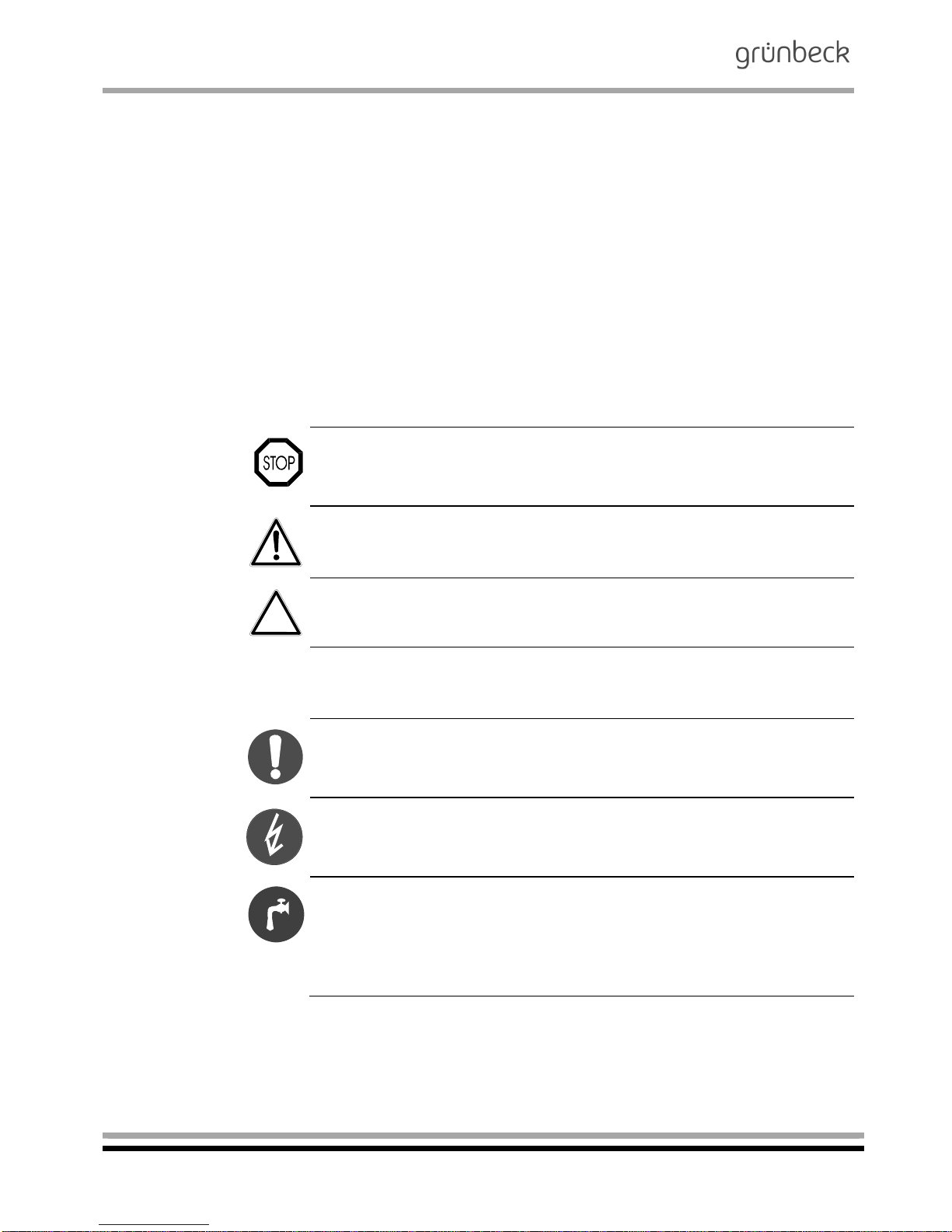
3.1 Symbols and
notes
Important information in this operation manual is emphasised by
symbols. Please pay particular attention to this information to ensure
the hazard-free, safe and efficient handling of the system.
Danger! Failure to adhere to this information will cause serious or
life-threatening injuries, extreme damage to property or inadmissible
impurities in the drinking water.
Warning! Failure to adhere to this information can cause injuries,
damage to property or impurities in the drinking water.
Caution! Failure to adhere to this information can result in damage
to the system or other objects.
Note: This symbol emphasises information and tips that facilitate
your work.
Tasks with this symbol may only be performed by Grünbeck's technical service/authorised service company or by persons expressly
authorised by Grünbeck.
Tasks with this symbol may only be performed by trained and qualified electrical experts according to the VDE guidelines or according
to the guidelines of a similar local institution.
Tasks with this symbol may only be performed by water suppliers or
approved installation companies. In Germany, the installation company must be registered in a water company installation directory as
per §12(2) AVBWasserV (German Ordinance on General Conditions
for the Supply of Water).
3.2 Operating personnel
Only allow persons who have read and understood this operation
manual to work with the system. Strictly observe the safety information.
Page 7
Iron / manganese removal
Demanganisation system GENO-mat MN-Z
Order no. 095 153 048-inter Edited by: nkes-mrie G:\BA-153048-INTER_095_GENO-MAT_MN-Z.DOCX
7
3.3 Intended use
The system may only be used for the purpose outlined in the product
description (chapter C). The guidelines in this operation manual as
well as the applicable local guidelines concerning drinking water protection, accident prevention and occupational safety must be observed.
In addition, intended use also implies that the system may only be
operated when it is in proper working order.
Any errors must be eliminated at once.
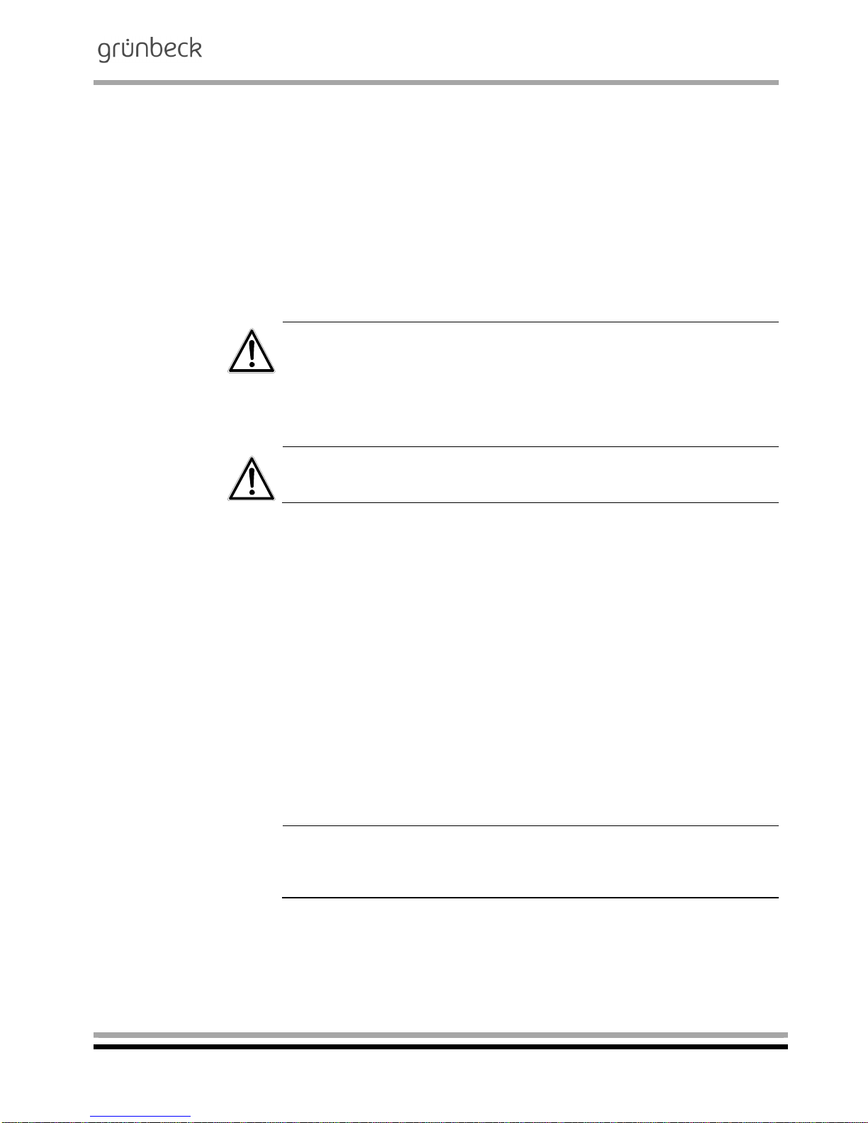
3.4 Protection from
water damage
Warning! To properly protect the installation site from water dam-
age:
a) a sufficient floor drain system must be available or
b) a water stop device (see chapter C Accessories) must be in-
stalled.
Warning! Floor drains that discharge to a lifting system will not work
in case of a power failure.
3.5 Indication of
specific dangers
Danger due to electrical energy! Do not touch electrical components with wet hands! Disconnect the system from the mains before
starting work on electrical system components! Have qualified experts replace damaged cables immediately.
Danger due to mechanical energy! System components can be subject to overpressure. Risk of injuries and damage to property due to
escaping water and unexpected movement of system parts.
Check pressure pipes regularly. Depressurise the system before
starting repair or maintenance work on the system.
Hazardous to health due to contaminated drinking water! The
system should be installed by a specialist company only. Strictly adhere to the operation manual! Ensure that there is sufficient flow,
and observe the relevant guidelines when starting up the system after extended periods of standstill. Perform inspections and maintenance at the intervals specified!
Note: By concluding a maintenance contract, you ensure that all of
the required tasks are performed on time. The intermediate inspections can be performed in-house.
Page 8
Iron / manganese removal
Demanganisation system GENO-mat MN-Z
Order no. 095 153 048-inter Edited by: nkes-mrie G:\BA-153048-INTER_095_GENO-MAT_MN-Z.DOCX
8
4 | Shipping and storage
Caution! The system can be damaged by frost or high tempera-
tures. In order to avoid damage of this kind:
Protect from frost during transportation and storage!
Do not install or store system next to objects which radiate a lot of
heat.
The system may only be transported and stored in its original pack-
ing. Ensure that it is treated with care and placed the right side up
(as indicated on the packaging).
5 | Disposal of used parts and consumables
Used parts and consumables should be disposed of or made available for recycling purposes according to the applicable local guidelines.
If consumables are subject to specific determination, observe the
corresponding instructions on the packaging.
If in doubt, contact your local waste disposal authority or the manufacturer for more information.
Page 9

Iron / manganese removal
Demanganisation system GENO-mat MN-Z
Order no. 095 153 048-inter Edited by: nkes-mrie G:\BA-153048-INTER_095_GENO-MAT_MN-Z.DOCX
9
B Basic information
1 | Laws, regulations, standards
In the interest of good health, rules cannot be ignored when it comes
to the processing of drinking water. This operation manual takes into
consideration the current regulations and stipulates information that
you will need for the safe operation of your demanganisation system.
Among other things, the set of rules stipulates that:
only approved companies are permitted to make major modifica-
tions to water supply facilities
and that tests, inspections and maintenance on installed devices
are to be performed at regular intervals.
2 | Designated application/area of application
The GENO-mat MN-Z demanganisation systems are designed for
the reduction of iron and/or manganese. They are used in the residential sector for private water supply plants with maximum values
of up to 3.0 mg/l of iron and 1.0 mg/l of manganese. If the systems
are operated properly and handled according to the operation manual, pure water values as required by the German Drinking Water
Ordinance (TrinkwV) can be achieved.
For an optimum reduction of iron and manganese, a pH value > 7.2
is required. A dosing system for oxidants has to be provided upstream of the demanganisation system.
However, should ammonium (> 0.1 mg/l) be detected in the raw water, an additional treatment step is required.
3 | Function
The demanganisation system GENO-mat MN-Z is operated with the
natural, catalytic filter material Fermanit. A central control valve automatically controls the operating cycles filtration - backwash - and first
filtrate.
Page 10

Iron / manganese removal
Demanganisation system GENO-mat MN-Z
Order no. 095 153 048-inter Edited by: nkes-mrie G:\BA-153048-INTER_095_GENO-MAT_MN-Z.DOCX
10
3.1 Filters
The raw water flows into the filter tank via the raw water inlet and
then, from top to bottom, through the catalytic filter material. By
means of an oxidation process, dissolved iron and manganese salts
are transformed into insoluble oxides and are deposited on the Fermanit material.
In this oxidation process, the Fermanit releases electrons to the iron
and manganese until the supply is exhausted. The electrons have to
be replaced continuously by dosing GENO-oxi plus (refer to product
data sheet).
By dosing oxidants, the oxidation and precipitation of iron and manganese already takes place prior to their contact with the Fermanit
material. Thanks to its catalytic properties a complete oxidation and
due to the excellent filtration characteristics, an optimum filtration are
achieved. The filtered pure water is then directed via the lower distributing nozzle and the riser pipe through the pure water outlet into
the piping system.
3.2 Backwashing
During the backwash process, the filter bed is forcibly flushed from
bottom to top and thus loosened up. Impurities retained during the
filtration process are washed out via the drain outlet at the control
valve. The demanganisation system must be backwashed every 6
days at the latest (for the setting refer to chapter F).
3.3 First filtrate
By an automatic switch-over of the central control valve, the filter
bed will forcibly be flushed from top to bottom. This first filtrate is discharged to the drain and afterwards, the demanganisation system
GNEO-mat MN-Z is ready for operation once again.
3.4 Regeneration/disinfection
For operating and hygienic reasons, the demanganisation system
must be regenerated every 6 months with GENO special granulate
or GENO-oxi plus.
3.5 Control unit
The demanganisation system GENO-mat MN-Z is time-controlled
via an electrical timer.
In order to properly use the automatic timer control, the time interval
between two filter sequences (backwash interval in days) must be
set.
Page 11
Iron / manganese removal
Demanganisation system GENO-mat MN-Z
Order no. 095 153 048-inter Edited by: nkes-mrie G:\BA-153048-INTER_095_GENO-MAT_MN-Z.DOCX
11
C Product description
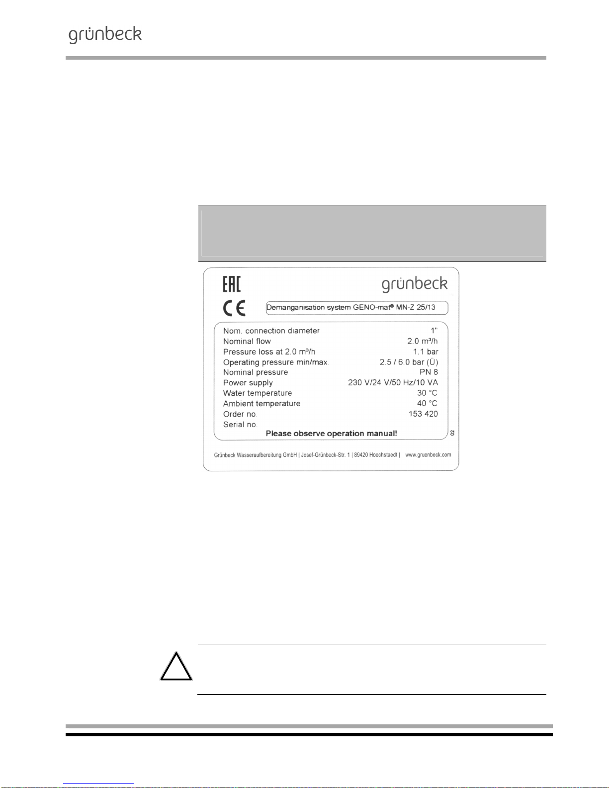
1 | Type designation plate
The type designation plate is located on the control head of the de-
manganisation system. In order to speed up the processing of your
inquiries or orders, please specify the data shown on the type designation plate of your system when contacting Grünbeck. Please add
the necessary information to the table below to have it readily available whenever necessary.
Demanganisation system
GENO-mat MN-Z
Serial number:
/
Order number:
Fig. C-1: Type plate for demanganisation system GENO-mat MN-Z
2 | Technical specifications
The GeNO-mat MN-Z demanganisation system is a single system
with integrated bypass for the supply of raw water during the backwash process. It is equipped with a timer control. The backwash is
initiated after a set time interval.
All system data is summarised in table C-1. The data refers to the
standard versions of the GeNO-mat MN-Z demanganisation system.
Possible deviations in case of special versions are communicated
separately, if applicable.
Caution! Electrically operated valves. In case of a power failure during the backwash, water may enter the drain. In the event of power
failure, check the system and shut-off the water supply, if necessary.
Page 12
Iron / manganese removal
Demanganisation system GENO-mat MN-Z
Order no. 095 153 048-inter Edited by: nkes-mrie G:\BA-153048-INTER_095_GENO-MAT_MN-Z.DOCX
12
Table C-1: Technical specifications Demanganisation system GENO-mat MN-Z
20/10 25/13 30/14 40/17 40/18 50/19 60/20
Connection data
Nominal connection diameter DN 25 (1") DN 40 (1½“)
Min. drain connection DN 50 DN 70
Nominal flow rate (depending on the iron concen-
tration)
[m³/h] 1.5 2.0 3.0 4.0 5.0 6.0 8.0
Power supply [V/Hz]
230 V, 50 Hz
operation with protective low voltage 24 V/50 Hz
Connected load [VA] 10
Protection type IP 54
Performance data
Nominal pressure (PN) 8.0
Min./max. operating pressure [bar] 2.5/6.0
Pressure loss at nominal flow [bar] 0.5 1.1 1.0 1.1 1.0 0.8 1.1
Dimensions and weights1)
Total height [mm] 1360 1620 1620 1900 1900 1870 2100
Exchanger tank
[mm]
210 260 340 370 420 550 620
Regeneration tank
[mm]
465 680
Height of regeneration tank [mm] 840 1010
Connection height/raw water piping [mm] 1160 1420 1420 1710 1710 1680 1910
Connection height/pure water piping [mm] 1210 1470 1470 1735 1735 1705 1935
Distance to wall [mm] 200 230 280 280 300 365 405
Depth of foundation [mm] 400 450 500 500 550 600 650
Length of foundation [mm] 1850 1950 2050 2050 2100 2250 2350
Operating weight (incl. water) [kg] 76 135 213 311 361 642 947
Filling volume and consumption data1)
Filter layer I, bottom, gravel 3.0 - 5.6 [kg] 10 10 25 25 25 50 50
Filter layer I, bottom, gravel 3.0 - 5.6 [l] 7 7 18 18 18 35 35
Filter layer I, bottom, gravel 3.0 - 5.6 (dimension a) [mm] 860 1170 1100 1400 1430 1320 1570
Filter layer II, middle, GENO Fermanit [kg] 25 50 50 100 125 200 325
Filter layer II, middle, GENO Fermanit [l] 12.5 25 25 50 63 100 163
Filter layer II, middle, GENO Fermanit (dimension b) [mm] 500 690 810 930 950 900 1020
Filter layer III, top, with quartz sand 0.4 – 0.8 [kg] 10 25 50 75 75 150 250
Filter layer III, top, with quartz sand 0.4 – 0.8 [l] 7 17 33 50 50 100 167
Filter layer III, top, with quartz sand 0.4 – 0.8 (dimen-
sion c)
[mm] 300 370 430 460 560 490 450
Free board [l] 7 12 30 22 40 74 71
Amount of regeneration agent required
Preparation amount [l] 302) 502) 602) 1002) 1002) 2002) 3002)
GENO special granulate [g] 105 175 210 350 350 700 1050
GENO-oxi plus [l] 5 9 11 17 17 35 53
Total waste water volume per regeneration (3 bar) [m³] 1 1.3 1.7 2 2.7 3.4 5.4
Ambient data
Duration of washing out (regeneration) [min.] 30
Duration of backwash [min.] 10
Backwash capacity [m³/h] 1.6 2.3 3.4 5.7
Max. water temperature [°C] 30
Max. ambient temperature [°C] 40
Order no. 153 … 410 420 430 440 450 460 470
Spare filter filling3)
Order no. 153 … 020 022 024 026 028 030 032
1)
All indications are approximate.
2)
If the liquid product GENO-oxi plus is used, the GENO-oxi plus amount must be subtracted from the batch size.
3)
all three filter layers
Page 13

Iron / manganese removal
Demanganisation system GENO-mat MN-Z
Order no. 095 153 048-inter Edited by: nkes-mrie G:\BA-153048-INTER_095_GENO-MAT_MN-Z.DOCX
13
Filter layer III top
Filter layer II middle
Filter layer I Bottom
Fig. C-2: Filling of filter layers
3 | Intended use
The system is adjusted to the water demand to be expected at the
installation site. It is not suitable for considerably differing performances. Do not exceed the peak flow under any circumstances.
The system may only be operated if all components are installed
properly. Safety devices and equipment must NEVER be removed,
bridged or tampered with.
Intended use of the device also implies that the information contained in this operation manual and all safety guidelines applying at
the installation site be observed. Furthermore, the maintenance and
inspection intervals must be respected.
Page 14

Iron / manganese removal
Demanganisation system GENO-mat MN-Z
Order no. 095 153 048-inter Edited by: nkes-mrie G:\BA-153048-INTER_095_GENO-MAT_MN-Z.DOCX
14
4 | Scope of supply
4.1 Basic equipment
Exchanger tank in double walled plastic housing.
Filter materials (gravel, GENO Fermanit, quartz sand).
Control valve made of red bronze with integrated timer control.
Water test kit for manganese.
Operation manual.
5 | Optional accessories
Note: It is possible to retrofit existing systems with optional components. Please contact your local Grünbeck representative or
Grünbeck’s headquarters in Höchstädt for more information.
PE tank 100 litre or 300 litre with litre scale and hand mixer to pre-
pare the regeneration solution. The tank features an integrated suction device.
Regeneration device 100 litres
(FE/MN-Z 20/10 – FE/MN-Z 40/18)
153 094
Regeneration device 300 litres
(FE/MN-Z 50/19 – FE/MN-Z 60/20)
153 095
Mounting set 1:
For convenient hydraulic connection.
Compact valve block R 1" female thread, integrated bypass with shut-off valve, shut-off
valves for hard and soft water, outlet for raw
water (e.g. garden hose), 2 connection
hoses
Mounting set R 1“ (up to type 30/14) 125 845
Complete dosing system consisting of dosing pump GP-2/40 (GP6/40), water meter 1" (1½"), dosing point, opaque suction lance,
dosing hose.
Dosing system suitable for
MN-Z 20/10 – MN-Z 30/14
Dosing system GENODOS DM-oxi 1"
163 420
Dosing system suitable for
MN-Z 40/17 – MN-Z 60/20
Dosing system GENODOS DM-oxi 1½"
163 430
Overflow valve GENODOS DM-oxi 1",1 1/2"
163 790
Page 15

Iron / manganese removal
Demanganisation system GENO-mat MN-Z
Order no. 095 153 048-inter Edited by: nkes-mrie G:\BA-153048-INTER_095_GENO-MAT_MN-Z.DOCX
15
6 | Consumables
Only use genuine consumables in order to ensure the reliable operation of the system.
6.1 Oxidants for the regeneration/disinfection of demanganisation systems
GENO special granulate1) (1 kg) 170 016
GENO special granulate1) (5 kg) 170 017
GENO-oxi plus (20 kg/19.7 litres) 170 029
1)
Note: Registration by the Federal Surveillance Authority for Opium
according to the Controlled Substances and Precursors Act required.
6.2 Test device for manganese measuring range 0.0 mg/l - 0.8 mg/l
and 1.0 mg/l - 10.0 mg/l
For the quantitative, colorimetric determination of dissolved manganese in the measuring range of 0.03 mg/l – 0.5 mg/l. Quick test kit
consisting of:
2 test vials and comparison scale
2 reagent Mn -1 A
1 reagent Mn - 2 A
1 reagent Mn - 3 A
170 124
6.3 Test kit for iron, measuring range 0.0 mg/l - 0.8 mg/l
and 1.0 mg/l - 10.0 mg/l
For the quantitative, colorimetric determination of dissolved iron in
the measuring range of 0.0 mg/l – 0.8 mg/l respectively 1.0 mg/l – 10
mg/l. Quick test kit consisting of:
1 test glass with 3 chambers and scale;
Test tablets (0.0 mg/l-0.8 mg/l) 30 tablets;
Test tablets (0.1 mg/l-10 mg/l) 30 tablets;
170 150
6.4 Spare filter filling, complete
Refer to table C-1 „Technical specifications“
Page 16

Iron / manganese removal
Demanganisation system GENO-mat MN-Z
Order no. 095 153 048-inter Edited by: nkes-mrie G:\BA-153048-INTER_095_GENO-MAT_MN-Z.DOCX
16
6.5 Wearing parts
Seals and control pistons are subject to a certain wear and tear in
the event of heavy duty. Wearing parts are listed below.
Note: Although these parts are wearing parts, we grant a limited
warranty period of 6 months. The same applies to electrical components.
Seals, control piston, injector, actuator
Fig. C-3: Control head
nominal connection diameter DN 25 (1")
Fig. C4: Control head
Nominal connection diameter DN 40
(1½")
Page 17

Iron / manganese removal
Demanganisation system GENO-mat MN-Z
Order no. 095 153 048-inter Edited by: nkes-mrie G:\BA-153048-INTER_095_GENO-MAT_MN-Z.DOCX
17
D Installation and operation
1 | General installation information
The installation site must offer adequate space. A foundation of a
sufficient size and adequate load carrying capacity has to be provided. The required connections must be provided prior to the installation. For dimensions and connection data, please refer to table D-
1.
Table D-1: Installation data Demanganisation system GENO-mat MN-Z
20/10 25/13 30/14 40/17 40/18 50/19 60/20
Connection data
Nominal connection diameter DN 25 (1") DN 40 (1½“)
Min. drain connection DN 50 DN 70
Nominal flow rate (depending on the iron con-
centration)
[m³/h] 1.5 2.0 3.0 4.0 5.0 6.0 8.0
Power supply [V/Hz]
230 V, 50 Hz
operation with protective low voltage 24 V/50 Hz
Connected load [VA] 10
Protection type IP 54
Dimensions and weights1)
Total height [mm] 1360 1620 1620 1900 1900 1870 2100
Exchanger tank
[mm] 210 260 340 370 420 550 620
Regeneration tank
[mm] 465 680
Height of regeneration tank [mm] 840 1010
Connection height/raw water piping [mm] 1160 1420 1420 1710 1710 1680 1910
Connection height/pure water piping [mm] 1210 1470 1470 1735 1735 1705 1935
Distance to wall [mm] 200 230 280 280 300 365 405
Depth of foundation [mm] 400 450 500 500 550 600 650
Length of foundation [mm] 1850 1950 2050 2050 2100 2250 2350
Operating weight (incl. water) [kg] 76 135 213 311 361 642 947
1)
All indications are approximate.
Note: For the installation of systems with optional accessories (refer
to Chapter C, item 5), also observe the operation manuals supplied
with these components.
Page 18

Iron / manganese removal
Demanganisation system GENO-mat MN-Z
Order no. 095 153 048-inter Edited by: nkes-mrie G:\BA-153048-INTER_095_GENO-MAT_MN-Z.DOCX
18
1.1 Water installation
It is imperative that you comply with certain regulations when installing the GENO-mat MN-Z demanganisation system. Additional
recommendations are given in order to facilitate the handling of the
system. The installation instructions described below are also illustrated in fig. D-2.
Mandatory regulations
The installation of the GeNO-mat MN-Z demanganisation system
represents a major interference with the drinking water system.
Therefore, only authorised experts may install such systems. In Germany, the installation company must be registered in a water company installation directory as per §12(2) AVBWasserV (German Ordinance on General Conditions for the Supply of Water).
Observe local and general installation guidelines.
Provide a drain connection to discharge the backwash water.
The installation room must have a floor drain (DN 100). If no floor
drain is available, a corresponding water stop device has to be installed.
Observe the flow direction!
Warning! Floor drains that discharge to a lifting system will not work
in case of a power failure.
Recommendations
Provide a sampling valve and a pressure gauge directly upstream
and downstream of the GeNO-mat MN-Z demanganisation system
(0 -10 bar). This simplifies the sampling for the regular determination of the iron concentration (functional check).
1.2 Electrical installation
A shock-proof plug is adequate for the electrical connection. However, it must comply with the specifications given in table D-1, may
not be further than 1.20m away from the GeNO-mat MN-Z demanganisation system and must carry constant voltage (do not couple
with light switch)!
Page 19

Iron / manganese removal
Demanganisation system GENO-mat MN-Z
Order no. 095 153 048-inter Edited by: nkes-mrie G:\BA-153048-INTER_095_GENO-MAT_MN-Z.DOCX
19
2 | Preliminary work
1. Unpack all system components.
2. Check for completeness and undamaged condition.
3. Place the filter tank at the designated location.
Extract from Table D-1
Table D-2: Filling volumes
1)
Demanganisation system GENO-mat MN-Z
20/10 25/13 30/14 40/17 40/18 50/19 60/20
Filling volumes and consumption data
Bottom filter layer I, gravel 3.0 - 5.6 [kg] 10 10 25 25 25 50 50
Bottom filter layer I, gravel 3.0 - 5.6 [l] 7 7 18 18 18 35 35
Filter layer I, bottom, gravel 3.0 - 5.6 (dimen-
sion a)
[mm] 860 1170 1100 1400 1430 1320 1570
Filter layer II, middle, GENO Fermanit [kg] 25 50 50 100 125 200 325
Filter layer II, middle, GENO Fermanit [l] 12.5 25 25 50 63 100 163
Filter layer II, middle, GENO Fermanit (dimen-
sion b)
[mm] 500 690 810 930 950 900 1020
Filter layer III, top, with quartz sand 0.4 – 0.8
[kg]
10 25 50 75 75 150 250
Filter layer III, top, with quartz sand 0.4 – 0.8
[l]
7 17 33 50 50 100 167
Filter layer III, top, with quartz sand 0.4 – 0.8
(dimension c)
[mm]
300 370 430 460 560 490 450
Free board, approx. [l] 7 12 30 22 40 74 71
1)
All indications are approximate.
Filter layer III Top
Filter layer II Middle
Filter layer I Bottom
Fig. D-1: Filling of filter layers
Page 20

Iron / manganese removal
Demanganisation system GENO-mat MN-Z
Order no. 095 153 048-inter Edited by: nkes-mrie G:\BA-153048-INTER_095_GENO-MAT_MN-Z.DOCX
20
Centre rising pipe,
Fill with filter material
1. Fill filter tank up to 50 % with water.
2. Check whether the riser pipe is covered by a protective cap, plug
on the protective cap, if necessary. The protective cap prevents
material from entering the riser pipe.
3. Centre the filter tank in the rising pipe.
4. Fill the tank with filter material by using the funnel supplied with
the system (refer to figure). Refer to Table D-2 for fill volumes.
Remove the protective cap,
fix the control head in place.
5. Fill up the filter tank with water
6. Centre the riser pipe precisely.
7. Clean the filter tank’s screw thread and the sealing surface for the
connection of the control valve from any filter material that might
be clinging to them.
8. Remove the protective cap from the riser pipe.
9. Put the control valve from above onto the rising pipe and fasten it
by turning it to the right.
Page 21

Iron / manganese removal
Demanganisation system GENO-mat MN-Z
Order no. 095 153 048-inter Edited by: nkes-mrie G:\BA-153048-INTER_095_GENO-MAT_MN-Z.DOCX
21
3 | How to connect the system
1. Establish the water connection as described in the erection drawing (fig. D-2 (a) (b). Observe the guidelines and recommendations
given in section 1.
Pump (provided by others)
Regeneration tank
for demanganisation (option)
Demanganisation system
GENO-mat MN-Z incl. filter material
Membrane expansion vessel
(provided by others)
Sampling valve
(on site)
Pressure gauge outlet pressure
(on site)
Pressure gauge inlet pressure
(on site)
Control valve operating voltage
24 V / 50 Hz
Contact water meter (scope of
supply, pos. 4)
GENODOS DM-oxi dosing (option)
Fig. D-2 (a) : Installation drawing for demanganisation system GENO-mat
MN-Z
Dimensions in Fig. D-2 (a); Extract from table D-1
Demanganisation system GENO-mat MN-Z
20/10 25/13 30/14 40/17 40/18 50/19 60/20
Dimensions and weights1)
A Total height [mm] 1360 1620 1620 1900 1900 1870 2100
B Exchanger tank
[mm] 210 260 340 370 420 550 620
C Regeneration tank
[mm] 465 680
D Height of regeneration tank [mm] 840 1010
E Connection height/raw water piping [mm] 1160 1420 1420 1710 1710 1680 1910
F Connection height/pure water piping [mm] 1210 1470 1470 1735 1735 1705 1935
G Distance to wall [mm] 200 230 280 280 300 365 405
H Foundation depth [mm] 400 450 500 500 550 600 650
I Foundation length [mm] 1850 1950 2050 2050 2100 2250 2350
1)
All indications are approximate.
10
Page 22

Iron / manganese removal
Demanganisation system GENO-mat MN-Z
Order no. 095 153 048-inter Edited by: nkes-mrie G:\BA-153048-INTER_095_GENO-MAT_MN-Z.DOCX
22
Caution! Dirt and corrosion particles might damage the system
(control valve). Flush the supply pipe prior to start-up.
2. Establish waste water connection as per DIN EN 1717. Shorten
the rinsing water hose to the length required and direct it to the
drain. Make sure that there is a free outlet (min. 20 mm) to the
drain. Secure the hose with suitable means to prevent the hose
from moving about (exiting regeneration water is pressurised).
Caution! Danger of damage and malfunction due to backflow of
waste water. Therefore, do not bend the hose and do not lead it
higher than the system height.
3. Connect the mains plug to the socket (cf. 1.2).
4. Water the system
In order to prevent the filter material from being washed out, it
must be watered for 24 hours.
Control valve
Raw water inlet
Filter tank
Raw water outlet
Drain connection
Fig. D-2 (b): Demanganisation system GENO-mat MN-Z, rear view
Page 23

Iron / manganese removal
Demanganisation system GENO-mat MN-Z
Order no. 095 153 048-inter Edited by: nkes-mrie G:\BA-153048-INTER_095_GENO-MAT_MN-Z.DOCX
23
E Commissioning
The work described below may only be performed by trained experts. We recommend to have the start-up performed by Grünbeck's
technical service/authorised service company.
Warning! Risk of bacterial growth due to stagnation! According to
VDI 6023, filling the system with drinking water before normal operation commences is prohibited.
The demanganisation system GENO-mat MN-Z must therefore only
first be connected to the drinking water system immediately prior to
commissioning.
1 | How to start up the system
1. Open the valve on the raw water inlet.
2. Open the valve at the pure water outlet.
3. Perform a visual check. Ensure that no water leaks from the system at any point.
4. Rinse out fine particles
The filter material contains a small amount of fine particles which
must be flushed by means of a backwash prior to start-up. Initiate
a manual regeneration
(refer to chapter F, item 1.4).
Note: The backwash process must be repeated until the backwash
water that flows to the drain in the process step "first filtrate" is clear.
5. Take a water sample at the sampling valve downstream of the
unit.
6. Determine the manganese concentration using the water test kit.
7. Complete the cover sheet and column 1 in the operating log.
Page 24

Iron / manganese removal
Demanganisation system GENO-mat MN-Z
Order no. 095 153 048-inter Edited by: nkes-mrie G:\BA-153048-INTER_095_GENO-MAT_MN-Z.DOCX
24
2 | Special treatment of the demanganisation system
As GENO-Fermanit is a natural product, it is not possible to rule out
the presence of manganese compounds as MnO, MnO2 or as
Mn2O3. This means that during commissioning, it may occur that the
manganese value is higher downstream of the system than in the inlet water. In this case, a special treatment should be performed.
The special treatment is performed using a kitchen salt solution
(NaCI).
Fill the regeneration unit (optional accessory, see chapter C, point
5) with saturated brine
(For quantities, see Table E-1).
Performing a special treatment
(For procedure, see chapter G, point 3).
Then perform a regeneration process with GENO special granulate
or
GENO-oxi plus (see chapter G, point 3.1).
Table E-1: Required brine volume Demanganisation system GENO-mat MN-Z
20/10 25/13 30/14 40/17 40/18 50/19 60/20
Required brine volume [l]
15 30 40 66 88 130 221
Caution! Special treatment only following consultation with the factory, or carried out by Grünbeck's technical service/authorised service company.
2.1 Continuous addition of GENO-oxi plus
Caution! The following instructions only apply when using the in-
tended system components (see chapter C, point 5).
When using other system components (a different GENODOS pump
or water meter), a special design is required (factory/sales department).
Installation in accordance with the installation drawing (see chapter
D, point 3, fig. D-2).
Following commissioning of the demanganisation system, the continuous addition of GENO-oxi plus should be carried out initially for
around 6 weeks. The stroke length of the GENODOS pump should
be set to 80%. After the run-in time, the stroke length can be reduced each week by 10 % until manganese breaks through (but to a
maximum of 30%). This means that the limit value has been
reached. Finally, increase the stroke length for subsequent operation
by 10%.
Page 25

Iron / manganese removal
Demanganisation system GENO-mat MN-Z
Order no. 095 153 048-inter Edited by: nkes-mrie G:\BA-153048-INTER_095_GENO-MAT_MN-Z.DOCX
25
Stipulations:
Iron content: mg/l
Manganese content: mg/l
Determination of the iron/manganese equivalent.
Specific iron/manganese equivalent value (SEV):
Fe - Mn equivalent
mg
l
= ironcontent
mg
l
+ 2x manganese content
mg
l
(With deferrisaton system installed upstream, the iron content must
not be taken into account)
Example
Iron content: 1.0 mg/l
Manganese content: 0.25 mg/l
Fe-Mn equivalent 1,0
mg
l
+2x manganese content0,25
mg
l
=1,5
mg
l
Table E-2: GENODOS pump setting
Dosing system GENODOS DM-oxi 1"
GP-2/40 with WM 0.33 l/Imp.
Dosing system GENODOS DM-oxi 1½"
GP-6/40 with WM 0.25 l/Imp.
Fe/Mn
equivalent
Dosing
volume
2)
[ml/m³]
Pump
factor1)
Pulse
division
position
1)
Fe/Mn
equivale
nt
Dosing volume
2)
[ml/m³]
Pump
factor1)
Pulse division
position1)
< 0.5 < 19 0.02 9 < 0.5 < 19 0.02 9
> 0.5 > 20 0.025 8 > 0.5 > 20 0.025 8
> 0.6 > 29 0.033 7 > 0.7 > 29 0.033 7
> 0.7 > 34 0.05 6 > 0.9 > 34 0.05 6
> 1.1 > 53 0.066 5 > 1.3 > 53 0.066 5
> 1.4 > 67 0.1 4 > 1.7 > 67 0.1 4
> 2.1 > 101 0.125 3 > 2.5 > 101 0.125 3
> 2.7 > 129 0.2 2 > 3.2 > 129 0.2 2
> 4.2 > 201 0.33 1
1)
The description of the operation/setting of the GENODOS pump can be found
in operation manual 118 940 (included with the GENODOSDM-oxi dosing
system)!
2)
Corresponding to a 2% potassium permanganate solution.
Note: The calculated pump settings are guide values only and must
be optimised on site. We work on the basis that the raw water is always free of ammonia and hydrogen sulphides!
Page 26

Iron / manganese removal
Demanganisation system GENO-mat MN-Z
Order no. 095 153 048-inter Edited by: nkes-mrie G:\BA-153048-INTER_095_GENO-MAT_MN-Z.DOCX
26
F Operation
1 | How to operate the control unit
The control unit regulates the operating processes of the demanganisation system.
1.1 How to set the
time
GENO-mat MN-Z demanganisation systems are factory-set so that
the automatic backwash is started at 2am each day (during the
night). Set the current time during commissioning or after a power
failure.
1. Loosen the screw on the housing cover (top right).
2. Open the housing cover.
3. Press and hold the red button (fig. F-1, pos. 6).
4. Turn the 24 hour disk until the reference arrow (fig. F-1, pos. 2)
points to the current time.
5. Release the red button (fig. F1, pos. 6).
Note: If the preset time for the backwash (2:00 am) is unfavourable
for internal reasons, set a time which deviates from the current time
on the 24 hour disk to adjust the starting time for the backwash.
Example:
Desired starting time of the backwash: 22:00
Move clock forward 4 hours.
1.2 How to set the
backwash interval
The maximum backwash interval is 12 days. Furthermore, an automatic backwash can be carried out after 6, 4, 3, 2 or 1 day(s) (factors of 12). Fig. F-1 indicates the setting for a backwash to be carried out every 2 days.
1. Determination of the backwash interval.
For hygienic reasons, a backwash should be carried out every 6
days (factory-setting).
If the differential pressure of the filter is > 0.3 bar above normal af-
ter 6 days due to a higher concentration of dirt in the water, a
backwash process should be initiated every 4 days or at even
shorter intervals.
The same applies in case of an early breakthrough of dirt parti-
cles.
Page 27

Iron / manganese removal
Demanganisation system GENO-mat MN-Z
Order no. 095 153 048-inter Edited by: nkes-mrie G:\BA-153048-INTER_095_GENO-MAT_MN-Z.DOCX
27
Backwash dial
Button for time setting
Hour dial
Reference arrow for current time and operating state
(black)
Reference arrow (red)
Reference point for operating state (white)
Day dial
Steel switching pin (in home position
moved to centre point, in switch position
moved outwards)
Fig. F-1: Control unit and operating elements "front view"
2. Push the switching pin (fig. F-1, pos. 5) outwards for the 1st day.
3. Set the other switching pins as required.
On all days where the switching pins are pushed outwards, the
backwash is initiated. In order to set, for example, a backwash interval of 3 days, the switching pins in positions 1, 4, 7 and 10 on
the day disk must be pushed outwards (fig. F-1, pos. 4).
1.3 How to read the
operating state
The current operating state may be read from the position of the reference point (fig. F-1, pos. 8) on the backwash wheel (fig. F-1, pos.
1).
The reference point
(fig. F-1, pos. 8) lies opposite the reference arrow
(fig. F-1, pos. 7).
Operating mode: pure water is available.
Page 28

Iron / manganese removal
Demanganisation system GENO-mat MN-Z
Order no. 095 153 048-inter Edited by: nkes-mrie G:\BA-153048-INTER_095_GENO-MAT_MN-Z.DOCX
28
All other settings from the
reference point (fig. F-1,
pos. 8).
Backwash; the backwash wheel (fig. F-1,
pos. 1) turns clockwise; the progress of
the backwash can be read from the position of the reference point (fig. F-1,
pos. 8).
The day disk (fig. F-1, pos. 4) turns counter-clockwise once in
12 days. The red reference arrow (fig. F-1, pos. 3) points to the position where a switching pin turned outwards initiates a backwash. In
the operating mode, the distance between the reference arrow
(fig. F-1, pos. 3) and the following switching pin which is turned outwards is an indication for the number of days until the next backwash.
1.4 How to initiate a
manual backwash
Manual regeneration should be initiated if
the differential pressure of the demanganisation system is more
than 0.3 bar above normal before the timer control initiates the
backwash.
the systems are restarted after longer periods of standstill.
maintenance or repair work has been carried out.
Irrespective of the set backwash interval and the time, the backwash
can be initiated manually at any time.
1. Check the operating status.
Only in operating mode:
2. Turn backwash wheel (fig. F-1, pos. 1) to the right by one catch
(note the click!).
The demanganisation system starts the backwash process, the
backwash wheel (fig. F-1, pos. 1) slowly turns clockwise. After approx. 3 hours, the backwash is terminated and the white reference
point (fig. F-1, pos. 8) is located opposite of the black reference arrow for the current time again (fig. F-1, pos. 7).
Page 29

Iron / manganese removal
Demanganisation system GENO-mat MN-Z
Order no. 095 153 048-inter Edited by: nkes-mrie G:\BA-153048-INTER_095_GENO-MAT_MN-Z.DOCX
29
G Maintenance and care
1 | Basic information
To guarantee the reliable function of the GENO-mat MN-Z demanganisation systems over a long period of time, some maintenance
work must be performed at regular intervals. This applies in particular to the backwash in the drinking water sector where the required
measures are defined in the pertinent regulations and guidelines. All
regulations and guidelines which apply at the installation site must
be strictly adhered to.
DIN EN 806-5 stipulates:
Inspection every 2 months
Maintenance every 6 months
The maintenance work has to be performed by the Grünbeck’s
technical service/authorised service company or by an authorised
specialist company.
An operation log must be kept in order to document the mainte-
nance work performed.
Note: By concluding a maintenance contract you ensure that all
maintenance work will be performed in due time.
The operation log is attached to this operation manual.
2 | Inspection (functional check)
You may perform the regular inspections yourself.
Overview: Inspection work
Determine inlet water (manganese, iron).
(Water test kit)
Determine pure water (manganese, iron).
(Water test kit)
Differential pressure of the system
Check control unit settings:
a) Time
b) Test raw water hardness
Page 30

Iron / manganese removal
Demanganisation system GENO-mat MN-Z
Order no. 095 153 048-inter Edited by: nkes-mrie G:\BA-153048-INTER_095_GENO-MAT_MN-Z.DOCX
30
Note: Minor deviations are normal and cannot be prevented technically. If you detect major deviations, please notify Grünbeck’s technical service/authorised service company.
Check the entire system for outward tightness.
Check control valve to drain for tightness (in operating mode).
3 | Maintenance
Maintenance work on the GENO-mat MN-Z demanganisation systems may only be performed by Grünbeck’s technical service/authorised service company or by an approved specialist.
An operation log must be kept for GeNO-mat MN-Z demanganisation systems. In this operation log, the customer service technician
records all maintenance and repair work performed. In case of malfunctions, this log helps to identify possible sources of error. In addition, the log documents the proper system maintenance.
Make sure that all maintenance work is recorded in the operation log.
Overview: Maintenance work
Read water pressure, flow pressure and if necessary water meter
reading.
Determine iron concentrations.
Check initiation of backwash.
Check control valve for tightness, replace wearing seals if neces-
sary, check the proper function of the drive motor of the control
valve, clean injector and sieve.
"Regenerate/disinfect" system.
Check the level of the filter material in the filter tank. Refill filter
material, if required.
Page 31

Iron / manganese removal
Demanganisation system GENO-mat MN-Z
Order no. 095 153 048-inter Edited by: nkes-mrie G:\BA-153048-INTER_095_GENO-MAT_MN-Z.DOCX
31
3.1 Regeneration/disinfection of GENO-mat MN-Z demanganisation systems
Note: We recommend to have the regeneration/disinfection performed by Grünbeck’s authorised technical service/authorised service company.
3.1.1 Oxidant
Designated area of application:
Oxidizing agents are used for the regeneration and disinfection of
deferrisation and demanganisation systems; they are also dosed upstream of deferrisation and demanganisation systems in order to
completely oxidise iron II and manganese II compounds.
The dosing and the dosing volumes depend on the iron and manganese concentrations contained in the raw water.
You can use either our GENO special granulate1) or
GENO-oxi plus (liquid).
3.1.2 Preparing the regeneration agent
Fill the regeneration tank with filtered water (for respective quanti-
ties refer to Table G-1). We recommend installing a filling tap in the
pure water pipe for this purpose.
Pour the GENO special granulate1) or GENO-oxi plus into the tank
and mix using the integrated hand mixer until the special granulate
has dissolved completely.
Install a suction hose between the regeneration tank and the ball
valve at the control valve.
1)
Note: Registration by the Federal Surveillance Authority for Opium
according to the Controlled Substances and Precursors Act required.
Table G-1: Amount of regeneration agent
required
Demanganisation system GENO-mat MN-Z
20/10 25/13 30/14 40/17 40/18 50/19 60/20
Preparation amount [l] 302) 502) 602) 1002) 1002) 2002) 3002)
GENO-oxi plus [l] 5 9 11 17 17 35 53
GENO special granulate1) [g] 105 175 210 350 350 700 1050
2)
If the liquid product GENO-oxi plus is used, the GENO-oxi plus amount must be subtracted from the batch size.
Page 32

Iron / manganese removal
Demanganisation system GENO-mat MN-Z
Order no. 095 153 048-inter Edited by: nkes-mrie G:\BA-153048-INTER_095_GENO-MAT_MN-Z.DOCX
32
3.1.3 Timer settings
For the regeneration/disinfection the corresponding regeneration
tank and the appropriate regeneration agent are required (refer to
3.1 preparation of the regeneration agent).
Flip the cover of the control valve to the side.
Initiate a manual regeneration (see chapter F, point 1.4).
Flip the timer to the right and wait for 10 minutes until limit switch 1
is free (fig. G-1, illustration 1) and the actuator of the control piston
has stopped.
Unplug mains plug.
Open the ball valve on the back of the control valve and suck the
regeneration agent from the connected regeneration tank.
Close the ball valve again after the regeneration agent has been
completely sucked off.
Reconnect mains.
Wait until limit switch 1 is pressed again (fig. G-1, illustration 2)
and the actuator of the control piston has stopped.
Unplug mains plug.
Flush for at least 30 minutes in order to wash out all residues of
the regeneration agent from the filter bed.
Reconnect mains.
The demanganisation system is ready for operation again when
the limit switches 1 and 2 are free (fig. G-1, illustration 3).
Screw cover back on.
Fig. G-1: Rear of timer
Page 33

Iron / manganese removal
Demanganisation system GENO-mat MN-Z
Order no. 095 153 048-inter Edited by: nkes-mrie G:\BA-153048-INTER_095_GENO-MAT_MN-Z.DOCX
33
3.2 Operation log
The operation log is located in chapter G, point 5 of this operation
manual. When commissioning the system, make sure to record all
data on the cover sheet of the operation log and fill in the first column of the checklist.
The customer service technician will fill in a column of the check list
whenever maintenance is performed. This document provides evidence of proper maintenance.
4 | Spare parts
You can order spare parts and consumables from your local
Grünbeck representative (refer to www.gruenbeck.com).
Page 34

Iron / manganese removal
Demanganisation system GENO-mat MN-Z
Order no. 095 153 048-inter Edited by: nkes-mrie G:\BA-153048-INTER_095_GENO-MAT_MN-Z.DOCX
34
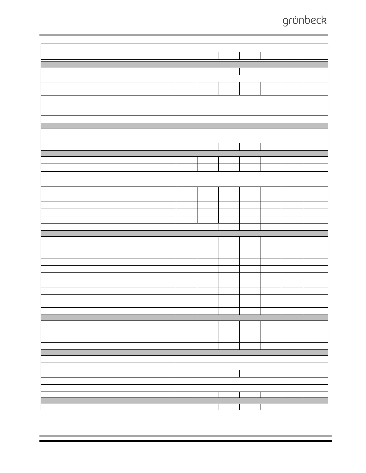
5 | Operation log
Customer
Name: ...............................................................................
Address: ............................................................................
..........................................................................................
..........................................................................................
Demanganisation system GENO-mat MN-Z
(Please check appropriate box)
Serial number ................. .........................................
Installed by ...................... .........................................
Filter: Make/type ......................... / ............................
20/10
25/13
30/14
40/17
40/18
50/19
60/20
Connection data: Drain connection DIN EN 1717 yes no
(Please check appropriate
box)
Floor drain available yes no
Page 35

Iron / manganese removal
Demanganisation system GENO-mat MN-Z
Order no. 095 153 048-inter Edited by: nkes-mrie G:\BA-153048-INTER_095_GENO-MAT_MN-Z.DOCX
35
Maintenance work on demanganisation system GENO-mat MN-Z
Checklist
Please enter measured values. Confirm checks with OK or enter repair work performed.
Maintenance performed (date)
Start-up
Measured values
Water pressure [bar] upstream
and downstream of the system
Flow pressure [bar] upstream and
downstream of the system
Water meter reading [m³]
Iron/manganese inlet (measured)
Iron/manganese pure water
(measured)
Inspections and checks on control unit and control head
Initiation of backwash checked
Injector and sieve cleaned
Control head checked for leaks
Function of drive motor checked
System "regeneration and disinfection"
System treated with special granulate
Connections, hose connections, seals
Seals and hose connections
checked
Miscellaneous
Remarks
Customer service technician
Company
Work time certificate (no.)
Signature
Page 36

Iron / manganese removal
Demanganisation system GENO-mat MN-Z
Order no. 095 153 048-inter Edited by: nkes-mrie G:\BA-153048-INTER_095_GENO-MAT_MN-Z.DOCX
36
Maintenance work on demanganisation system GENO-mat MN-Z
Checklist
Please enter measured values. Confirm checks with OK or enter repair work performed.
Maintenance performed (date)
Measured values
Water pressure [bar] upstream
and downstream of the system
Flow pressure [bar] upstream and
downstream of the system
Water meter reading [m³]
Iron/manganese inlet (measured)
Iron/manganese pure water
(measured)
Inspections and checks on control unit and control head
Initiation of backwash checked
Injector and sieve cleaned
Control head checked for leaks
Function of drive motor checked
System "regeneration and disinfection"
System treated with special granulate
Connections, hose connections, seals
Seals and hose connections
checked
Miscellaneous
Remarks
Customer service technician
Company
Work time certificate (no.)
Signature
Page 37

Iron / manganese removal
Demanganisation system GENO-mat MN-Z
Order no. 095 153 048-inter Edited by: nkes-mrie G:\BA-153048-INTER_095_GENO-MAT_MN-Z.DOCX
37
Maintenance work on demanganisation system GENO-mat MN-Z
Checklist
Please enter measured values. Confirm checks with OK or enter repair work performed.
Maintenance performed (date)
Measured values
Water pressure [bar] upstream
and downstream of the system
Flow pressure [bar] upstream and
downstream of the system
Water meter reading [m³]
Iron/manganese inlet (measured)
Iron/manganese pure water
(measured)
Inspections and checks on control unit and control head
Initiation of backwash checked
Injector and sieve cleaned
Control head checked for leaks
Function of drive motor checked
System "regeneration and disinfection"
System treated with special granulate
Connections, hose connections, seals
Seals and hose connections
checked
Miscellaneous
Remarks
Customer service technician
Company
Work time certificate (no.)
Signature
Page 38

Iron / manganese removal
Demanganisation system GENO-mat MN-Z
Order no. 095 153 048-inter Edited by: nkes-mrie G:\BA-153048-INTER_095_GENO-MAT_MN-Z.DOCX
38
Maintenance work on demanganisation system GENO-mat MN-Z
Checklist
Please enter measured values. Confirm checks with OK or enter repair work performed.
Maintenance performed (date)
Measured values
Water pressure [bar] upstream
and downstream of the system
Flow pressure [bar] upstream and
downstream of the system
Water meter reading [m³]
Iron/manganese inlet (measured)
Iron/manganese pure water
(measured)
Inspections and checks on control unit and control head
Initiation of backwash checked
Injector and sieve cleaned
Control head checked for leaks
Function of drive motor checked
System "regeneration and disinfection"
System treated with special granulate
Connections, hose connections, seals
Seals and hose connections
checked
Miscellaneous
Remarks
Customer service technician
Company
Work time certificate (no.)
Signature
 Loading...