

Page 1
Operation manual
Reverse osmosis system GENO-OSMO-X
with GENO-tronic operating element
and GENO-OSMO-X controller
starting from software version V1.11
Edition: April 2018
Order no. 124 750 927-inter
Page 2

Page 3

Reverse osmosis system
GENO-OSMO-X
Order no. 134 750 927-inter Edited by: phar/mrie G:\BA-750927-inter_134_GENO-OSMO_X.docx
1
Table of contents
AGENERAL ............................................................................................................................................................................................ 4
1 | P
REFACE
..................................................................................................................................................................................................... 4
2 | H
OW TO USE THIS OPERATION MANUAL
............................................................................................................................................................ 4
3 | G
ENERAL SAFETY INFORMATION
..................................................................................................................................................................... 5
3.1Symbols and notes .............................................................................................................................................................................. 5
3.2Operating personnel ............................................................................................................................................................................ 5
3.3Appropriate application ........................................................................................................................................................................ 5
3.4Protection from water damage ............................................................................................................................................................. 6
3.5Indication of specific dangers ............................................................................................................................................................... 6
4 | S
HIPPING AND STORAGE
................................................................................................................................................................................ 6
5 | D
ISPOSAL OF USED PARTS AND MATERIALS
...................................................................................................................................................... 6
BBASIC INFORMATION ........................................................................................................................................................................ 7
1 | L
AWS, REGULATIONS, STANDARDS
.................................................................................................................................................................. 7
2 | W
ATER
........................................................................................................................................................................................................ 7
3 | F
UNCTIONAL PRINCIPLE OF REVERSE OSMOSIS
................................................................................................................................................. 8
CPRODUCT DESCRIPTION .................................................................................................................................................................. 9
1 | T
YPE DESIGNATION PLATE
.............................................................................................................................................................................. 9
2 | F
UNCTIONAL DESCRIPTION
........................................................................................................................................................................... 10
3 | T
ECHNICAL SPECIFICATIONS
......................................................................................................................................................................... 15
4 | A
PPROPRIATE APPLICATION
......................................................................................................................................................................... 16
4.1System idle time ................................................................................................................................................................................. 16
5 | A
PPLICATION LIMITS
.................................................................................................................................................................................... 17
6 | S
COPE OF SUPPLY
...................................................................................................................................................................................... 18
6.1Standard equipment ........................................................................................................................................................................... 18
6.2Optional accessories .......................................................................................................................................................................... 19
6.3Consumables ..................................................................................................................................................................................... 22
6.4Wearing parts .................................................................................................................................................................................... 23
DINSTALLATION ................................................................................................................................................................................. 24
1 | G
ENERAL INSTALLATION INSTRUCTIONS
........................................................................................................................................................ 24
1.1Preliminary work ................................................................................................................................................................................ 24
2 | W
ATER INSTAL LATION
.................................................................................................................................................................................. 24
3 | H
OW TO CONNECT THE SYSTEM
.................................................................................................................................................................... 25
4 | E
LECTRICAL INSTALLATION
........................................................................................................................................................................... 26
4.1Circuit diagram of power distribution .................................................................................................................................................. 26
4.2Connections within the GENO-OSMO-X control unit and the GENO-tronic operating element: ........................................................ 28
4.3Connections within the GENO-OSMO-X reverse osmosis system .................................................................................................... 29
4.4Connections to other subsystems - system output ............................................................................................................................. 30
4.5Connections to other subsystems – Residual hardness monitoring system NX1CQ1 for pre-treatment by water softener ................. 30
4.6Connections to other subsystems – Dosing pump RO1 P2 for antiscalant pre-treatment ....................................................................... 31
4.7Connections within the OSMO-X reverse osmosis system – AVRO pre-treatment RO1B5 ................................................................ 31
4.9Subsystems water softener and/or pressure booster interconnected via RS485 data line – Connection of terminating resistors ...... 32
4.10 Connections to other subsystems – Pre-treatment by water softener ................................................................................................. 32
4.11Connections to other sub-systems – Pressure booster installed downstream .................................................................................... 32
4.12Connections to other subsystems – Optional signals or accessories ................................................................................................. 33
ESTART-UP ......................................................................................................................................................................................... 34
1 | H
OW TO FLUSH THE SYSTEM
........................................................................................................................................................................ 34
1.1How to flush off the preservation agent .............................................................................................................................................. 34
FOPERATION ...................................................................................................................................................................................... 36
1 | I
NTRODUCTION
........................................................................................................................................................................................... 36
2 | S
CREEN LAYOUT OF THE
GENO-
TRONIC OPERATING ELEMENT
........................................................................................................................ 36
2.1Home screen ..................................................................................................................................................................................... 36
2.2Info level of GENO-OSMO-X.............................................................................................................................................................. 37
2.3Change, save, reject parameters ....................................................................................................................................................... 38
2.4Acknowledgement of errors/signals ................................................................................................................................................... 39
2.5Screen saver ...................................................................................................................................................................................... 40
3 | S
YSTEM RANGE
.......................................................................................................................................................................................... 40
3.1System menu I ................................................................................................................................................................................... 40
3.2Data logging on an SD card ............................................................................................................................................................... 42
3.2System menu II .................................................................................................................................................................................. 45
3.3Software version ................................................................................................................................................................................ 45
4 | SUB-
SYSTEM
GENO-OSMO-X
REVERSE OSMOSIS SYSTEM
........................................................................................................................... 45
4.1 User programming level ..................................................................................................................................................................... 46
4.2Installer level (Code 113) ................................................................................................................................................................... 48
4.3Customer service level ....................................................................................................................................................................... 54
4.4Extended customer service level I ...................................................................................................................................................... 54
4.5Extended customer service level II ..................................................................................................................................................... 54
4.6Counter readings, error memory ........................................................................................................................................................ 55
4.7Key operation ..................................................................................................................................................................................... 56
4.8Reset of counter readings .................................................................................................................................................................. 56
4.9Memory of operating parameters ....................................................................................................................................................... 56
5 | P
ERMEATE TANK
......................................................................................................................................................................................... 57
6 | PRE-
TREATMENT BY MEANS OF ANTISCALANT DOSING
..................................................................................................................................... 58
6.1Operator menu ................................................................................................................................................................................... 59
6.2Customer Service level ...................................................................................................................................................................... 5 9
GTROUBLESHOOTING ....................................................................................................................................................................... 60
1 | B
ASIC INFORMATION
.................................................................................................................................................................................... 60
2 | H
OW TO REMEDY WARNINGS
........................................................................................................................................................................ 61
3 | T
ROUBLESHOOTING
.................................................................................................................................................................................... 64
HMAINTENANCE ................................................................................................................................................................................. 7 0
1 | B
ASIC INFORMATION
.................................................................................................................................................................................... 70
2 | I
NSPECTION (FUNCTIONAL CHECK
) ................................................................................................................................................................ 70
3 | M
AINTENANCE
............................................................................................................................................................................................ 7 1
4 | O
PERATION LOG
......................................................................................................................................................................................... 72
Page 4

Reverse osmosis system
GENO-OSMO-X
Order no. 134 750 927-inter Edited by: phar/mrie G:\BA-750927-inter_134_GENO-OSMO_X.docx
2
Publisher's information
All rights reserved.
Copyright by Grünbeck Wasseraufbereitung GmbH
Printed in Germany
Effective with the date of edition indicated on the cover sheet.
-We reserve the right to modifications, especially with regard to
technical progress-
Reprints, translations into foreign languages, electronic storage
or copying of this operation manual only with explicit written approval of Grünbeck Wasseraufbereitung GmbH.
Any type of duplication not authorised by Grünbeck Wasseraufbereitung is a copyright violation and subject to legal action.
Responsible for contents:
Grünbeck Wasseraufbereitung GmbH
Josef-Grünbeck-Str. 1, 89420 Hoechstaedt/Germany
Phone +49 9074 41-0 Fax +49 9074 41-100
www.gruenbeck.de service@gruenbeck.de
Print: Grünbeck Wasseraufbereitung GmbH
Josef-Grünbeck-Str. 1, 89420 Hoechstaedt/Germany
Page 5
Reverse osmosis system
GENO-OSMO-X
Order no. 134 750 927-inter Edited by: phar/mrie G:\BA-750927-inter_134_GENO-OSMO_X.docx
3
EU Declaration of Conformity
This is to certify that the system designated below meets the safety and health requirements of
the applicable European guidelines in terms of its design, construction and execution.
If the system is modified in a way not approved by us, this certificate is void.
Manufacturer: Grünbeck Wasseraufbereitung GmbH
Josef-Grünbeck-Str. 1
89420 Hoechstaedt/Germany
Responsible for documentation:
Markus Pöpperl
System designation: Reverse osmosis system GENO-OSMO-X
System size: 200, 400, 800, 1200, 1600, 2200, 3000
Serial number: refer to type designation plate
Applicable guidelines: Machinery Directive (2006/42/EC)
EMC Directive (2014/30/EU)
Applied harmonised standards,
in particular:
DIN EN ISO 12100: 2011-03
DIN EN 61000-6-2: 2006-03
DIN EN 61000-6-3: 2011-09
Applied national standards
and technical
specifications,
in particular:
City, date and signature: Hoechstaedt, 30.04.2018 p.p.
M. Pöpperl
Dipl.-Ing. (FH)
Function of signatory: Head of Department for Technical Product Design
Page 6

Reverse osmosis system
GENO-OSMO-X
Order no. 134 750 927-inter Edited by: phar/mrie G:\BA-750927-inter_134_GENO-OSMO_X.docx
4
A General
1 | Preface
Thank you for opting for a Grünbeck product. Backed by decades
of experience in the area of water treatment, we provide solutions
for all kind of processes.
All Grünbeck systems and devices are made of high-quality materials. This ensures reliable operation over many years, provided
you treat your water treatment systems with the required care.
This operation manual assists you with important information.
Therefore, please read the entire operation manual before installing, operating or maintaining the system.
Customer satisfaction is our prime objective and providing customers with qualified advice is crucial. If you have any questions
concerning this device, possible extensions or general water and
waste water treatment, our field staff, as well as the experts at
our headquarters in Hoechstaedt, are available to help you.
Advice and assistance
For advice and assistance please contact your local representative (see www.gruenbeck.de) or get in touch with our service
centre which can be reached during office hours:
Phone: +49 9074 41-333
Fax: +49 9074 41-120
Email: service@gruenbeck.de
We can connect you with the appropriate expert more quickly if
you provide the required system data.
2 | How to use this operation manual
This operation manual is intended for the operators of our sys-
tems. It is divided into several chapters and a letter is assigned to
each of them in alphabetical order. In order to find the specific information you are looking for, check for the corresponding chapter
on page 3.
Page 7
Reverse osmosis system
GENO-OSMO-X
Order no. 134 750 927-inter Edited by: phar/mrie G:\BA-750927-inter_134_GENO-OSMO_X.docx
5
3 | General safety information
3.1 Symbols and notes
Important information in this operation manual is characterised
by symbols. Please pay particular attention to this information to
ensure the hazard-free, safe and efficient handling of the system.
Danger! Failure to adhere to this information will cause serious
or life-threatening injuries, extreme damage to property or inadmissible contamination of the drinking water.
Warning! Failure to adhere to this information may cause injuries, damage to property or contamination of the drinking water.
Attention! Failure to adhere to this information may result in
damage to the system or other objects.
Note: This symbol characterises information and tips to make
your work easier.
Tasks with this symbol may only be performed by Grünbeck's
technical service/authorised service company or by persons expressly authorised by Grünbeck.
Tasks with this symbol may only be performed by qualified electrical experts according to the VDE guidelines or according to
the guidelines of a similar local institution.
Tasks with this symbol may only be performed by water companies or approved installation companies. In Germany, the installation company must be registered in a water company installation directory as per §12(2) AVBWasserV (German Ordinance on
General Conditions for the Supply of Water).
3.2 Operating personnel
Only persons who have read and understood this operation
manual are permitted to work with the system. The safety guidelines are to be strictly adhered to.
3.3 Appropriate application
The system may only be used for the purpose outlined in the
product description (chapter C). The guidelines in this operation
manual as well as the applicable local guidelines concerning the
drinking water protection, accident prevention and occupational
safety must be adhered to.
In addition, appropriate application also implies that the system
may only be operated when it is in proper working order.
Any malfunctions must be repaired at once.
Page 8
Reverse osmosis system
GENO-OSMO-X
Order no. 134 750 927-inter Edited by: phar/mrie G:\BA-750927-inter_134_GENO-OSMO_X.docx
6
3.4 Protection from water
damage
Warning! In order to properly protect the installation site against
water damage:
a sufficient floor drain system must be available or
a safety device (see chapter C Accessories) must be in-
stalled.
Warning! In case of a power failure, floor drains with a discharge to a lifting system will be out of operation.
3.5 Indication of
specific dangers
Danger due to electrical energy! Do not touch electrical parts
with wet hands! Disconnect the system from mains before starting work on electrical parts of the system. Have qualified experts
replace damaged cables immediately.
Danger due to mechanical energy! System parts may be subject
to overpressure. Danger of injury and damage to property due to
escaping water and unexpected movement of system parts.
Check pressure pipes regularly. Depressurise the system before
starting repair or maintenance work on the system.
Hazardous to health due to contaminated drinking water! The
system may only be installed by a specialist company. The operation manual must be strictly adhered to! Ensure that there is
sufficient flow. The pertinent guidelines must be followed for
starting-up after extended periods of standstill. Inspections and
maintenance must be performed at the intervals specified!
Note: By concluding a maintenance contract, you ensure that all
of the required tasks are performed on time. You may perform
the interim inspections yourself.
4 | Shipping and storage
Attention! The system may be damaged by frost or high tem-
peratures. In order to avoid damage of this kind:
Protect from frost during transportation and storage!
Do not install or store system next to objects which radiate a lot
of heat.
The system may only be transported and stored in its original
packing. Ensure that it is handled with care and placed the right
side up (as indicated on the packing).
5 | Disposal of used parts and materials
Used parts and materials are to be disposed of, or made availa-
ble for recycling purposes, according to the applicable local
guidelines.
If a material is subject to specific regulations, adhere to the instructions indicated on the packing.
If in doubt, contact your local waste disposal authority or the
manufacturer for more information.
Page 9

Reverse osmosis system
GENO-OSMO-X
Order no. 134 750 927-inter Edited by: phar/mrie G:\BA-750927-inter_134_GENO-OSMO_X.docx
7
B Basic information
1 | Laws, regulations, standards
In the interest of good health, rules cannot be ignored when it
comes to the processing of drinking water. This operation manual takes into consideration the current regulations and stipulates information that you will need for the safe operation of your
water treatment system.
Among other things, the regulations stipulate that
only approved companies are permitted to make major modi-
fications to water supply facilities
and that tests, inspections and maintenance on installed de-
vices are to be performed at regular intervals.
2 | Water
Due to dynamic substance and water cycles, harmful elements,
which are only partly and only slowly biodegradable are increasingly released into nature. Over time, these elements therefore
accumulate in ground and surface water. Removing them again
from natural water bodies represents a particular challenge.
Grünbeck rises to this challenge and aims at generating unpolluted drinking and process water.
The water works provide us with pure drinking water that is suit-
able for consumption. However, if the water is to be used for
technical purposes, further treatment is frequently required.
Page 10
Reverse osmosis system
GENO-OSMO-X
Order no. 134 750 927-inter Edited by: phar/mrie G:\BA-750927-inter_134_GENO-OSMO_X.docx
8
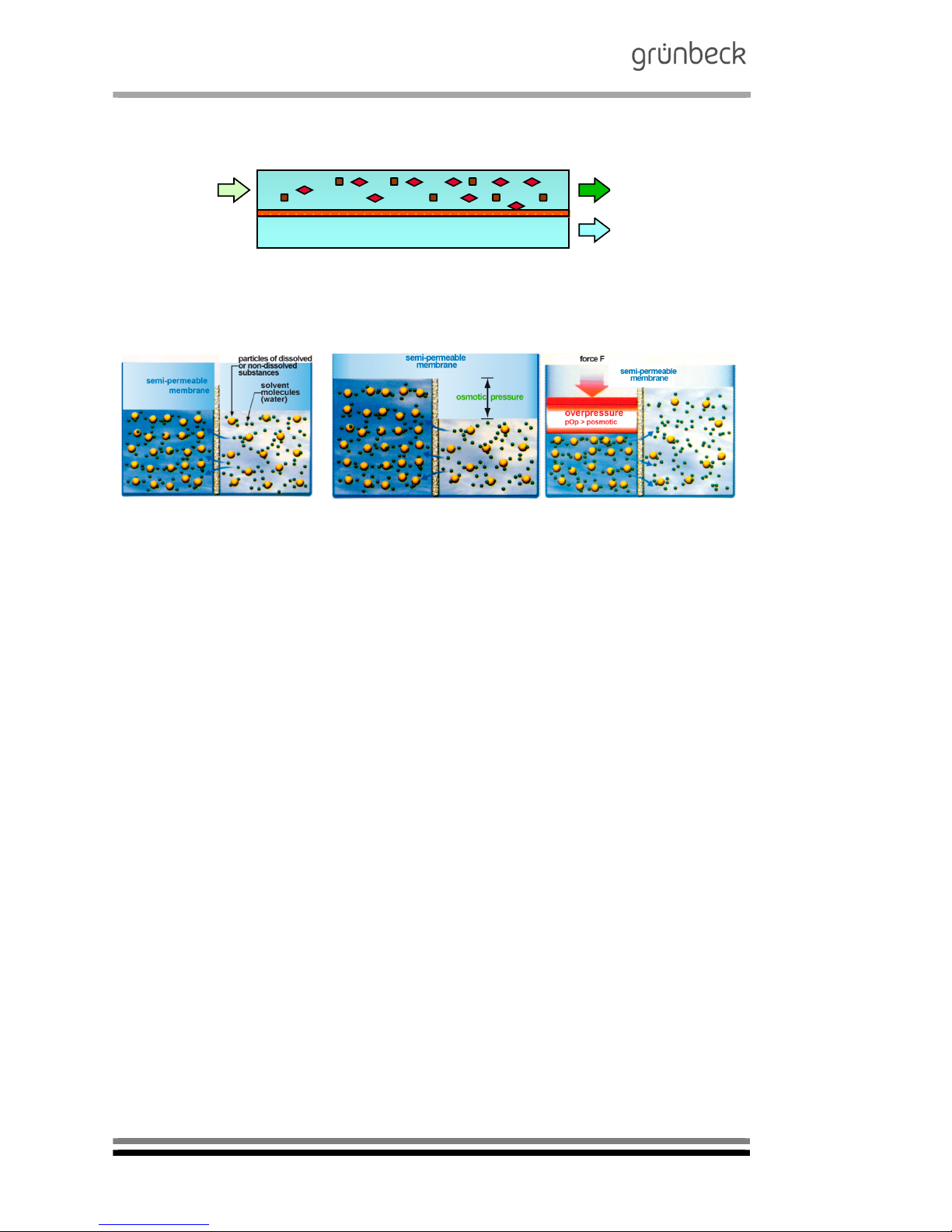
3 | Functional principle of reverse osmosis
Principle:
Pre-treated feed
water
Concentrate:
Permeate
Fig. B-1: Functional principle
Osmosis Osmotic pressure Reversed osmosis
Solution of high
concentration
Solution of low
concentration
Solution of high
concentration
Solution of low
concentration
Solution of high
concentration
(concentrate)
Solution of low
concentration
(permeate)
Fig. B-2: Reverse osmosis principle
In the osmosis process, watery solutions of different concentrations are separated by a semi-permeable membrane. In keeping
with the law of nature, the concentrations try to equalise. On the
side of the higher original concentration, the so-called "osmotic"
pressure is generated.
In case of reverse osmosis, this osmotic pressure is countered
by a higher pressure. The consequence: the process proceeds
in the reverse direction. A particular advantage of the reverse
osmosis technology compared to other water treatment processes is the fact that - apart from the removal of dissolved salts
- bacteria, germs and dissolved organic substances are also reduced.
Page 11
Reverse osmosis system
GENO-OSMO-X
Order no. 134 750 927-inter Edited by: phar/mrie G:\BA-750927-inter_134_GENO-OSMO_X.docx
9
C Product description
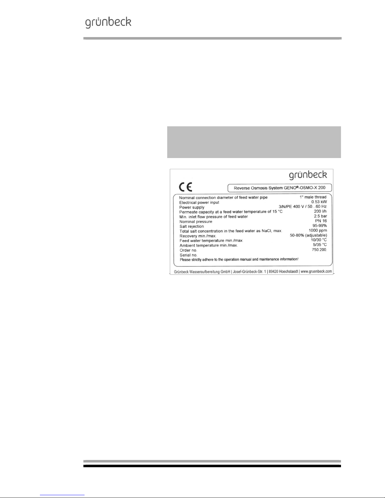
1 | Type designation
plate
Please specify the data shown on the type designation plate of
your GENO-OSMO-X reverse osmosis system in order to speed
up the processing of enquiries or orders. Please copy the indicated information to the table below in order to have it handy
whenever necessary.
Reverse osmosis system
GENO-OSMO-X:
Serial number:
Order no.:
Fig. C-1: Type designation plate of the reverse osmosis system GENO-OSMO-X
Page 12
Reverse osmosis system
GENO-OSMO-X
Order no. 134 750 927-inter Edited by: phar/mrie G:\BA-750927-inter_134_GENO-OSMO_X.docx
10
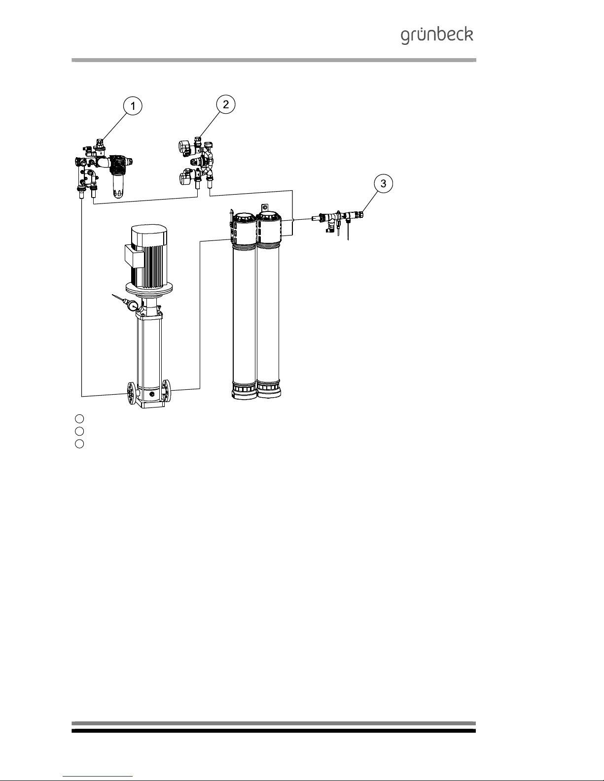
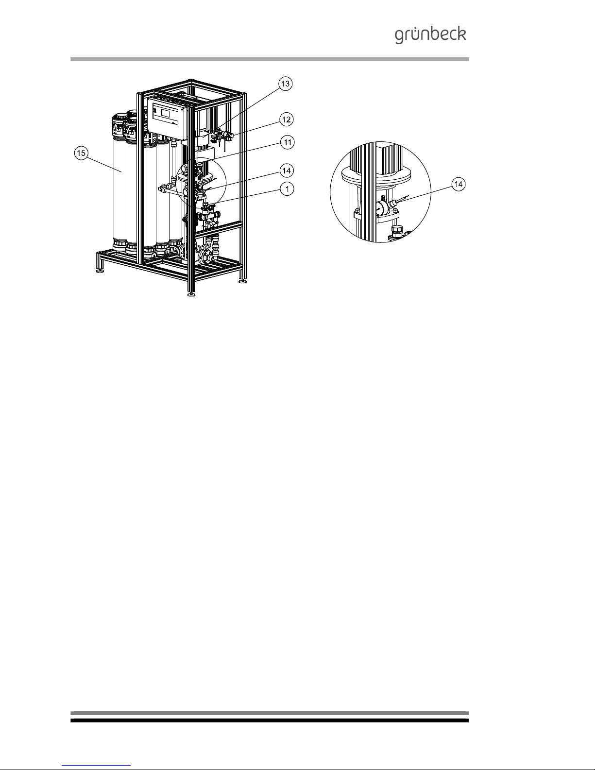
2 | Functional description
Feed water
Concentrate to drain
Permeate
Fig. C-2: System design of the reverse osmosis system GENO-OSMO-X
1
2
3
Page 13
Reverse osmosis system
GENO-OSMO-X
Order no. 134 750 927-inter Edited by: phar/mrie G:\BA-750927-inter_134_GENO-OSMO_X.docx
11
Feed water inlet
BL1
Connection 1“ or 1¼ (male thread), flat sealing, for feed water
connection by others on site
Note: Provide connection by means of water meter screw connection.
Solenoid valve
for feed water
RO1V1
During the permeate production, this valve is always open. Following the system stop (tank full), the valve remains open for
the programmed flushing volume of the membrane(s).
Fine filter
RO1F1
Pre-filtration of the feed water incl. pressure reducer (pre-set)
4.0 bar and integrated pressure gauge for feed water pressure.
Flow sensor
feed
RO1CF2
Via pulse signal to the control unit.
Feed = Concentrate recirculation + Permeate + Concentrate to
drain.
Pressure switch for
minimum pressure
RO1CP1
To prevent the high-pressure pump from running dry. Switches
time-delayed after opening the solenoid valve for feed water.
Flow sensor
feed water
RO1CF1
Via pulse signal to the control unit.
Feed water = Permeate + Concentrate to drain.
Adjusting valve concentrate to drain with drive
RO1V3
To automatically adjust the volume flow concentrate to drain (recovery). During the permeate production, this portion of the water flow permanently flows to the drain. The volume flow is subject to the system size. In case of tank "full" as well as in case of
a system failure, the valve always opens the entire cross section
in combination with the solenoid valve for feed water.
Pressure reducer
concentrate
RO1H4
To improve the regulation accuracy of the adjusting valves (set
to 6 bar)
Adjusting valve
concentrate recirculation
with drive
RO1V2
For automatic adjustment of the volume flow concentrate recirculation. The volume flow is subject to the system size.
Sampling valve
concentrate
RO1H1
Allows manual quality determination via sampling valve.
Connection concentrate
to drain
BL2
1“ male thread, flat sealing
Note: Provide for connection via water meter screw connection.
Permeate connection
BL3
1“ male thread, flat sealing
Note: Provide for connection via water meter screw connection.
High-pressure pump
RO1P1
Centrifugal pump system (frequency-controlled) that generates
the operating pressure required for the membrane. Pump operates upon permeate demand from the level control located in the
permeate tank. By means of the frequency converter, the
pump's revolution speed is adapted in a way that the nominal
permeate capacity is achieved.
1
2
3
4
5
6
7
8
9
10
11
12
13
Page 14

Reverse osmosis system
GENO-OSMO-X
Order no. 134 750 927-inter Edited by: phar/mrie G:\BA-750927-inter_134_GENO-OSMO_X.docx
12
Pressure switch
maximum pressure
RO1CP3
Prevents the system's operating pressure from exceeding
16 bar.
Membrane
RO1B1
Reverse osmosis membrane to generate the permeate.
Flow sensor permeate
RO1CF3
Via pulse signal at the control unit.
Sampling valve
permeate
RO1H5
Allows manual quality determination via sampling valve.
Conductivity
measurement
RO1CQ1
Conductivity sensor according to the 2-electrode principle (temperature-compensated (RO1CT1)) for the continuous measurement of the permeate conductivity. The measuring results are indicated in the control unit.
Fig. C-3: Reverse osmosis system GENO-OSMO-X hydro module
for feed water
14
15
16
17
18
Page 15

Reverse osmosis system
GENO-OSMO-X
Order no. 134 750 927-inter Edited by: phar/mrie G:\BA-750927-inter_134_GENO-OSMO_X.docx
13
Fig. C-4: Reverse osmosis system GENO-OSMO-X hydro module
for concentrate
Fig. C-5: Reverse osmosis system GENO-OSMO-X hydro module for permeate
Page 16
Reverse osmosis system
GENO-OSMO-X
Order no. 134 750 927-inter Edited by: phar/mrie G:\BA-750927-inter_134_GENO-OSMO_X.docx
14
Fig. C-6: Reverse osmosis system GENO-OSMO-X 3000 with fine filter,
hydraulic connections, membrane and high-pressure pump
Page 17
Reverse osmosis system
GENO-OSMO-X
Order no. 134 750 927-inter Edited by: phar/mrie G:\BA-750927-inter_134_GENO-OSMO_X.docx
15
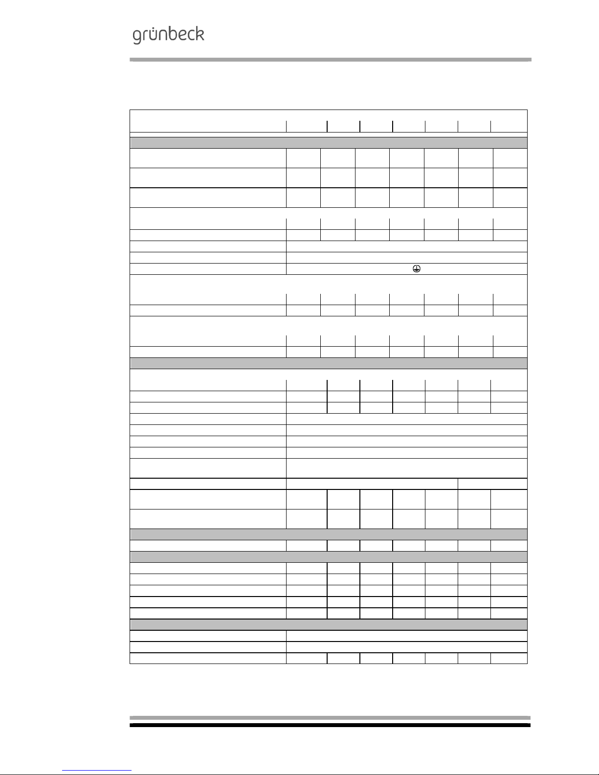
3 | Technical specifications
Table C-1: Technical specifications Reverse osmosis system GENO-OSMO-X
200 400 800 1200 1600 2200 3000
Connection data
Nominal connection diameter (male thread)
of feed water inlet
1“
1“ 1“ 1“ 1“
1 ¼“ 1 ¼“
Nominal connection diameter (male thread)
of permeate outlet
1“
1“ 1“ 1“ 1“ 1“ 1“
Nominal connection diameter (male thread)
of concentrate outlet
1“
1“ 1“ 1“ 1“ 1“ 1“
Min. drain connection
Without optional AVRO DN 50 DN 50 DN 50 DN 50 DN 50 DN 50 DN 50
With optional AVRO DN 50 DN 50 DN 50 DN 100 DN 100 - -
Power supply [V/Hz] 3/N/PE, 400 V/50...60 Hz
Min. power outlet provided on site 5.5 kW / C 20 A / 2.5 mm²
Protection/protection class
IP 54/
Power input in case of unpressurised delivery of the permeate into a tank at a switching frequency of the frequency
converter of 8 kHz and an inlet pressure of 4 bar in the feed water
Recovery of 80 % [kW] 0.53 0.87 0.94 1.40 1.74 2.10 2.30
Recovery of 50 % [kW] 0.53 0.88 0.94 1.30 1.60 - -
Power input if the permeate is delivered directly to the consumers with a supply pressure of 3.8 bar at a switching
frequency of the frequency converter of 8 kHz and an inlet pressure of 4 bar in the feed water.
Recovery of 80 % [kW] 0.86 1.44 1.60 2.00 2.31 2.30 2.80
Recovery of 50 % [kW] 0.81 1.20 1.41 1.90 2.11 - -
Performance data
Permeate capacity at a
Feed water temperature of 10 °C [l/h] 170 340 680 1020 1360 1870 2550
Feed water temperature of 15 °C [l/h] 200 400 800 1200 1600 2200 3000
Feed water temperature of 15 °C [m³/d] 4.8 9.6 19.2 28.8 38.4 52.8 72.0
Min. inlet flow pressure of feed water [bar] 2.5
Min. outlet pressure of permeate [bar] 0.5
Nominal pressure PN 16
Salt rejection 95 – 99 %
Total salt concentration in the feed water as NaCl, max.
[ppm] 1000
Recovery min./max. [%] 50-80 (adjustable) 65-80 (adjustable)
Volume flow concentrate to drain at a
recovery of 80%. (at 15°C)
[l/h] 50 100 200 300 400 550 750
Feed water volume flow (15 °C)
drain at a recovery of 80%.
[l/h] 250 500 1000 1500 2000 2750 3750
Filling volumes and consumption data
Number of modules (size 4") [pcs.] ½ 1 2 3 4 6 8
Dimensions and weights
System width [mm] 900 900 1035 1035 1170 1170 1170
System height [mm] 1700 1700 1700 1700 1700 1700 1700
System depth [mm] 675 675 675 675 675 675 675
Room height/installation height, min. [mm] 1800 1800 1800 1800 1800 1800 1800
Operating weight, approx. [kg] 100 115 145 170 195 240 290
General
Feed water temperature, min./max. [°C] 10/301)
Ambient temperature, min./max. [°C] 5/35
Order no. 750 200 750 210 750 220 750 230 750 240 750 250 750 260
1)
For temperatures of feed water > 20 °C a separate configuration of the system is required.
Page 18

Reverse osmosis system
GENO-OSMO-X
Order no. 134 750 927-inter Edited by: phar/mrie G:\BA-750927-inter_134_GENO-OSMO_X.docx
16
4 | Appropriate application
The reserve osmosis system is designed for the demineralisa-
tion of drinking water according to the German Drinking Water
Ordinance (TrinkwV). The generated water is primarily used for
industrial applications.
A corresponding pre-treatment is required and the application
limits (paragraph 5) must be adhered to.
Note: In case of water that does not comply with the stipulations
of the German Drinking Water Ordinance (TrinkwV), a water
analysis is required beforehand.
The continuous permeate capacity is subject to the temperature
and was defined at 15°C. The permeate capacity decreases by
up to 3 % per degree centigrade of the feed water temperature .
Note: This reverse osmosis system adjusts the permeate capacity automatically subject to the temperature. The recovery (concentrate to drain) as well as the concentrate recirculation are
adapted to the modified permeate capacity.
The system is adjusted to the permeate requirements to be ex-
pected at the installation site, it is not suitable for major deviations.
The system may only be operated if all components are installed
properly. Safety devices and equipment must NEVER be removed, bridged or tampered with.
Appropriate application of the device also implies that the information contained in this operation manual and all safety guidelines applying at the installation site be observed. Furthermore,
the maintenance and inspection intervals have to be observed.
4.1 System idle time
If the system is out of operation for more than 14 days, it must
be preserved by Grünbeck's technical customer service/authorised service company. The maximum time, the system can remain in the preserved condition is 6 months.
In case the down time is longer, the system must be preserved
again in regular intervals by Grünbeck's technical customer service/authorised service company. Prior to resuming operation,
the preserving agent must be flushed from the system.
Page 19

Reverse osmosis system
GENO-OSMO-X
Order no. 134 750 927-inter Edited by: phar/mrie G:\BA-750927-inter_134_GENO-OSMO_X.docx
17
5 | Application limits
For the application of the reverse osmosis system, the limit val-
ues stipulated in the German Drinking Water Ordinance represent the upper limits for the admissible substances contained in
the water.
Total hardness < 0.1 °dH
1)
(0.18 °f; 0.018 mmol/l)
Free chlorine not detectable
Iron < 0.10 mg/l
Manganese < 0.05 mg/l
Silicate < 15 mg/l
Chlorine dioxide not detectable
Turbidity < 1 FTU
Colloid index (SDI) < 3
pH range 3-9
1)
Different application limits for the total hardness do apply for
the optional pre-treatment AVRO resp. antiscalant.
Note: The permeate originating from the reverse osmosis system is not potable but requires additional treatment (blending,
hardening) if it is to be used as drinking water.
Page 20

Reverse osmosis system
GENO-OSMO-X
Order no. 134 750 927-inter Edited by: phar/mrie G:\BA-750927-inter_134_GENO-OSMO_X.docx
18
6 | Scope of supply
6.1 Standard equipment
Control unit with 4.3" graphics touch panel to indicate the op-
erating state and system values. Voltage-free contacts to relay advance warnings and safety shut-downs. Digital input for
priority permeate production in times when electricity tariffs
are low (smart metering). Fully automatic monitoring and control of the system parameters permeate flow, monitoring of
the permeate conductivity by means of limit value default settings in the control unit, recovery, concentrate recirculation
and pump frequency (subject to the water temperature). Recording of measured data on integrated SD card. Possibility
to interconnect systems installed upstream or downstream
(water softener, dosing system, permeate tank, pressure
booster) and to operate them by remote control.
Power distribution with mains switch and automatic circuit
breakers as feeding point for power supply provided by others on site.
High-pressure centrifugal pump made of stainless steel
1.4401 to supply the reverse osmosis membrane(s).
Ultra-low pressure reverse osmosis membrane(s), installed in
pressure pipe made of high-strength PE.
Three-part hydro module made of red bronze, chemically
nickel-plated, featuring pressure gauges, adjusting resp. solenoid valves and sampling valves. Flow sensors integrated
in the hydro module, volume measurement of the system
flows permeate, concentrate and concentrate recirculation.
The permeate hydro module features a conductivity measuring cell (temperature-compensated).
Pipework between pump and reverse osmosis membrane
made of high-pressure resistant PE pipes and PP compression fittings.
High-quality system rack made of anodised aluminium to
house all system components.
A ventilation device to be mounted onto the concentrate pipe
provided by others on site.
Fine filter incl. pressure reducer, completely preassembled in
system inlet.
Installation and operation manual.
Page 21
Reverse osmosis system
GENO-OSMO-X
Order no. 134 750 927-inter Edited by: phar/mrie G:\BA-750927-inter_134_GENO-OSMO_X.docx
19
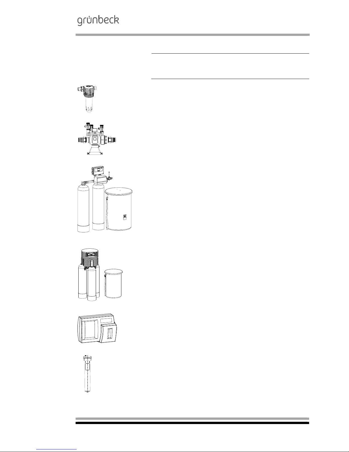
6.2 Optional accessories
Note: It is possible to retrofit existing systems with optional components. Please contact your local Grünbeck representative or
Grünbeck’s headquarters in Hoechstaedt for details.
BOXER K 1" drinking water filter
Filter cartridge for pre-filtration
101 210
Euro system separator GENO-DK 2
To secure devices and systems endangering the
drinking water according to DIN 1988, part 4
GENO-DK 2 DN 15
GENO-DK 2 DN 20
132 510
132 520
GENO-mat duo WE-X water softener
Fully automatic double water softener based on
the ion exchange principle for the generation of
fully softened water with volume-controlled regeneration.
-For larger systems, please inquire-
186 100
Delta-p water softener
Fully automatic triple water softener based on the
ion exchange principle for the generation of fully/
partially softened water with volume-controlled regeneration.
- For larger systems, please inquire -
185 100
GENO-softwatch Komfort
For automatic monitoring of the limit value for
residual/total hardness (water hardness).
172 500
GENO-activated carbon filter AKF 600
To reduce the chlorine concentration contained in
the water.
- For larger filters, please inquire -
109 160
Page 22
Reverse osmosis system
GENO-OSMO-X
Order no. 134 750 927-inter Edited by: phar/mrie G:\BA-750927-inter_134_GENO-OSMO_X.docx
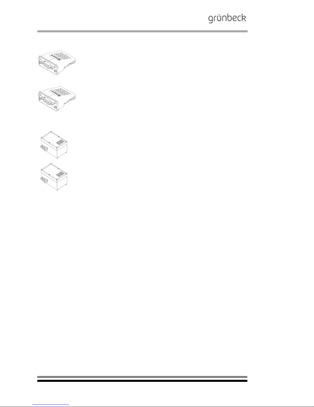
20
Communication module Profibus DP
For connection to a Profibus DP „Master“
750 160
Communication module BACnet IP
For connection to a BACnet IP „Master“
750 170
Communication module Modbus RTU
For connection to a Modbus RTU „Master“
750 175
Voltage-free signals
For connection to a BMS/CMS
750 180
Analogue signals 4-20 mA
For connection to a BMS/CMS
750 185
Page 23
Reverse osmosis system
GENO-OSMO-X
Order no. 134 750 927-inter Edited by: phar/mrie G:\BA-750927-inter_134_GENO-OSMO_X.docx
21
Safety device protectliQ:A20
Product for protection against water damage in one
and two-family homes.
- For additional versions, please inquire -
126 400
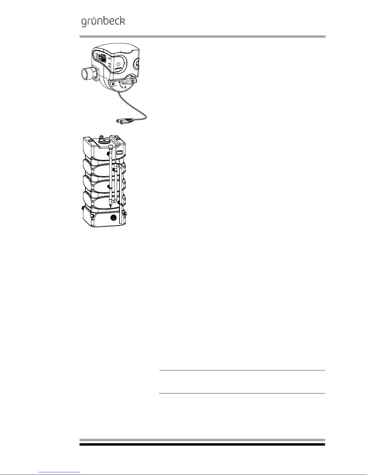
Pure water tank for intermediate storage of permeate flowing unpressurised from GENO-reverse osmosis systems
Tank design:
All tanks are pre-assembled, with PVC overflow
pipe as well as connections for the permeate inlet
and the suction line of the pressure booster system.
Grey PE. Hand hole with removable screw cap.
Basic pure water tank
RT-X 1000 with sterile air filter and level sensor
Useful capacity approx. 850 litres
l 780 / w 990 / total height 2000 mm
1)
712 480
Additional tank RT for
basic pure water tank
Useful capacity approx. 850 litres
l 780 / w 780 / total height 2100 mm
1)
712 405
Basic pure water tank
RT-X 1000
2)
with level sensor
Useful capacity approx. 850 litres
l 780 / w 1000 / total height 2050 mm
1)
712 490
1)
Tank height incl. connecting pieces.
For larger tanks, please inquire
2)
No sterile overflow as siphon
- overflow as down pipe
Additional tank without overflow loop,
incl. 2 connecting lines, id=36 mm.
Note: A maximum of four supply tanks can be combined.
Page 24

Reverse osmosis system
GENO-OSMO-X
Order no. 134 750 927-inter Edited by: phar/mrie G:\BA-750927-inter_134_GENO-OSMO_X.docx
22
Pressure booster system
GENO FU-X 2/40-1 N
Compact, pressure-controlled pump aggregate
consisting of a centrifugal pump completely made
of stainless steel as well as an integrated pressure and contact water meter. Control electronics
with increase in capacity, backlit graphical display.
Operating switch, operating log via SD card, voltage-free signal / fault contact, non-return valve,
shut-off valve for every pump (suction and pressure side) and membrane pressure expansion
vessel with forced flow.
Delivery rate: max. 1.2-4.2 m³/h
Delivery height max. 18.2 - 45.6 m
Power supply: 230 V / 50 Hz
Power input 1 kW
Connections: DN 25 / DN 32
Protection: IP 55
730 640
Pressure booster system
GENO FU-X 2/40-2 N
Description as for single pressure booster system,
however, with the possibility for time-/load switchover.
- For additional pressure booster systems,
please inquire -
730 641
6.3 Consumables
Only use genuine consumables in order to ensure the reliable
operation of the system.
GENO-replacement filter element, with protective
cylinder
Packing unit: 2 pcs
103 061
RO-membrane with seal 4“ x 40“
Reverse osmosis system GENO-OSMO-X 400 -
GENO-OSMO-X 3000
Packing unit: 1 pc
750 261
RO-membrane with seal 4“ x 21“
Reverse osmosis system GENO
-
OSMO-X 200
Packing unit: 1 pc
750 293
Activated carbon filter element MKCA
Reverse osmosis system GENO
-
OSMO-X 200
Packing unit: 1 pc
109 615
Page 25

Reverse osmosis system
GENO-OSMO-X
Order no. 134 750 927-inter Edited by: phar/mrie G:\BA-750927-inter_134_GENO-OSMO_X.docx
23
6.4 Wearing parts
Seals and valves are subject to a certain wear and tear. Wearing
parts are listed below.
Note: Although these are wearing parts, we grant a limited warranty period of 6 months.
Solenoid valves, adjusting valves, water meters, seals
Fig. C-7: Hydro module
Face seal of high-pressure pump
Fig. C-8: High-pressure pump
Page 26

Reverse osmosis system
GENO-OSMO-X
Order no. 134 750 927-inter Edited by: phar/mrie G:\BA-750927-inter_134_GENO-OSMO_X.docx
24
D Installation
1 | General Installation Instructions
The installation site must provide adequate space. Only the left
side (pressure pipes) of the system may be placed flush to the
wall. In front, behind and on the right side of the system, adequate
clearance for installation and service work must be provided
(> 50 cm). A foundation of a sufficient size and adequate load carrying capacity must be provided. The required connections must
be provided prior to the installation. For dimensions and connection data, please refer to table C-1.
1.1 Preliminary work
Unpack all system components.
Check for completeness and soundness.
Place the reverse osmosis system at the designated location.
Note: Also observe the operation manuals that have been supplied with the optional accessories (see chapter C-6.2) for your
system (if applicable).
2 | Water installation
Certain binding rules must always be observed when installing a
reverse osmosis system. Additional recommendations are given
in order to facilitate the handling of the system. The installation
instructions described below are also illustrated in fig. D-1.
Binding rules
The installation of a reverse osmosis system represents a major
interference with the drinking water system. Therefore, only authorised experts may install such systems.
Please observe the local installation guidelines and the gen-
eral regulations.
Install a drinking water filter upstream of the system (e.g.
BOXER K).
A system separator must be installed upstream as well.
Install a water softener upstream.
Mount an activated carbon filter, if necessary (take water
analysis into consideration).
Provide a drain connection (minimum DN 50) to discharge
the concentrate.
Note: If the concentrate is directed to a lifting system, the delivery
rate of the lifting system should at least have the concentrate volume flow indicated in table C-1.
Warning! The installation site must have a floor drain. If no floor
drain is available, an adequate safety device needs to be installed (refer to option C-9).
Warning! In case of a power failure, floor drains with a discharge to a lifting system will be out of operation.
Page 27

Reverse osmosis system
GENO-OSMO-X
Order no. 134 750 927-inter Edited by: phar/mrie G:\BA-750927-inter_134_GENO-OSMO_X.docx
25
3 | How to connect the system
Remove the protective caps at the feed water, permeate and
concentrate to drain connections of the system.
Connect the feed water.
Connect the concentrate to drain according to DIN 1988 and
install the pipe aeration above system level.
Make the connection between permeate outlet and supply
tanks.
BOXER K 1" drinking water filter
Reverse osmosis system GENO-OSMO-X
System separator GENO-DK 2
Permeate tank with sterile air filter and level sensor
Delta-p water softener
Pressure booster system GENO FU-X 2/40-1 N
GENO-softwatch Komfort
Activated carbon filter AKF
Fig. D-1: Installation drawing
Note: The feed, concentrate resp. permeate pipe provided by
others on site must feature a provision to separate the pipes
(e. g. a screw connection).
Note: The permeate and concentrate pipes have to be made of
corrosion-proof material.
1 6
2 7
3
8
4
5
Page 28

Reverse osmosis system
GENO-OSMO-X
Order no. 134 750 927-inter Edited by: phar/mrie G:\BA-750927-inter_134_GENO-OSMO_X.docx
26
4 | Electrical installation
As the reverse osmosis system GENO-OSMO-X features a frequency converter for the high-pressure pump, problems with the
residual current circuit breaker installed in the feeder may occur.
We therefore recommend:
Use of an AC/DC sensitive RCCB with a response threshold
of 300 mA.
For the power supply of the system, a power outlet 3 x 400 V /
50 Hz/L/N/PE with a fuse protection of 20 A has to be provided
by others on site.
The aluminium system rack must be connected to the equipotential bonding on-site. The earth wire must have a minimum cross
section of 6 mm² Cu or 10 mm² Al.
The necessary connecting materials (screw, hammer nuts,
washers, etc.) are located in a bag in the system power distributor (see Chapter F-4.1).
The connection to the equipotential bonding is required because
the speed-controlled high-pressure pump has a ground leakage
current of > 10 mA during its designated operation.
4.1 Circuit diagram of power distribution
The power distribution features the mains switch of the
GENO OSMO-X system and is accessible if the
GENO-OSMO-X control unit is flipped downwards. If required,
the entire "production line" (softening + residual hardness monitoring or antiscalant dosing, reverse osmosis, pressure booster
system) can be supplied by the power distribution.
The power line of an antiscalant dosing pump is plugged into the
mains socket of the power distribution in order to be able to
quickly replace it during servicing.
Page 29

Reverse osmosis system
GENO-OSMO-X
Order no. 134 750 927-inter Edited by: phar/mrie G:\BA-750927-inter_134_GENO-OSMO_X.docx
27
Page 30

Reverse osmosis system
GENO-OSMO-X
Order no. 134 750 927-inter Edited by: phar/mrie G:\BA-750927-inter_134_GENO-OSMO_X.docx
28
4.2 Connections within the GENO-OSMO-X control unit and the
GENO-tronic operating element:
The following connections are pre-set at the factory and must
not be modified:
Linux operating element
Power supply of programming board
From terminal of circuit board to terminal of programming board
91 +24 V= 8
92 mass 7
Serial connection RS 485
88 RS 485 A 11
89 RS 485 B 10
90 RS 485 GND 9
Fuses of circuit board
F1 T2A Main fuse of power input
F2 T0.63 A 24 V = solenoid valves, step motors
F3 T0.5A Programming board 24 V=
Page 31

Reverse osmosis system
GENO-OSMO-X
Order no. 134 750 927-inter Edited by: phar/mrie G:\BA-750927-inter_134_GENO-OSMO_X.docx
29
4.3 Connections within the GENO-OSMO-X reverse osmosis system
The following connections are preset internally at the factory and
must not be modified:
From
GENO-OSMO-X
control unit
to component Line Signal
1 Mains switch housing lid H05VV-F 5G1.5 mm² L From mains
switch
2 N
3 L To mains
switch
4 N
PE PE
5 230 V~ feed from
power distribution
RO1E2
38 H05VV-F 3G0.75 mm² L
6 39 N
PE 40 PE
12 Frequency converter
of high-pressure pump
RO1P1A1
1 LiYcY 7x0.25 mm² + 24 V= WH Release FU
13 2 IN BN
56 10 + 24 V= GY Fault signal
FU (
57 11 DI 6 PK
40 6 4-20 mA YE Desired value
FU
41 7 GND GN
PE Shield
20 Feed water solenoid valve
RO1V1
H05VV-F 2x0.5 mm² + 24 V= (clocked for power reduction
21 GND
28 Regulating valve concentrate
to drain
RO1V3
(step motor)
LiYY 7x0.25 mm² (blue
strand is not used)
Ph1 GN
29 Ph1 WH
30 Com1 BN
31 Ph2 PK
32 Ph2 YE
33 Com2 GY
34 Regulating valve concentrate
recirculation KR RO1V2
(step motor)
LiYY 7x0.25 mm² (white
strand is not used)
Ph1 GN
35 Ph1 BU
36 Com1 BN
37 Ph2 PK
38 Ph2 YE
39 Com2 GY
42 Temperature measurement
RO1CT1
LiYcY 4x0.25 mm² Pt 100 BN
43 GN
PE Conductivity measuring cell
RO1CQ1 cell constant 0,1
K= 0.1 1/cm Shield
44 WH
45 YE
46 Conductivity measuring cell
RO1CQ1 cell constant 0,1
LiYcY 4x0,25 mm² K= 0,1 1/cm
47 WH
YE
54 Pressure switch for minimum
pressure RO1CP1
LiYY 2x0.5 mm² + 24 V= WH
55 DI 5 BN
58 Pressure switch for maximum
pressure RO1CP3
LiYY 2x0.5 mm² + 24 V= WH
59 DI 10 BN
73 Feed water flow sensor
RO1CF1
LiYY 3x0.25 mm² +12 V= WH
74 [pulse] GN
75 GND BN
76 Flow sensor Feed
RO1CF2
LiYY 3x0.25 mm² +12 V= WH
77 [pulse] GN
78 GND BN
79 Flow sensor ermeate
RO1CF3
LiYY 3x0.25 mm² +12 V= WH
80 [pulse] GN
81 GND BN
Page 32

Reverse osmosis system
GENO-OSMO-X
Order no. 134 750 927-inter Edited by: phar/mrie G:\BA-750927-inter_134_GENO-OSMO_X.docx
30
4.4 Connections to other subsystems - system output
From
GENO-OSMO-X
control unit
to component Line Signal Colour
System output Tank
68 Digital signals BB1 for regis-
tration of filling level of pure
water tank BB1CL1
LiYY 5x0.25 mm² +24 V=
69 System OFF BB1CL1
70 System ON / bypass closed BB1CL2
71 Bypass closed / dry run pro-
tection of pressure booster
OFF
BB1CL3
72 Dry-run protection of pressure
booster ON
BB1CL4
Or alternatively
86 Analogue signals BB1 for
registration of filling level of
pure water tank BB1CL1
LiYY 3x0.34 mm² + 24 V= WH
87 IN BN
PE Shield YE-GN
24 RO1 V4 (first permeate)
or
RO1 V7 (blending valve)
H05VV-F 2x0.5 mm² 24 V= BN
25 GND BU
System output Online
84 Pressure measuring transducer
RO1 CP2 0…6 bar
LiYcY 2x0.25 mm² + 24 V= WH
85 In BN
PE Shield
4.5 Connections to other subsystems – Residual hardness monitoring system NX1CQ1
for pre-treatment by water softener
From
GENO-OSMO-X
control unit
to component Line Signal
14 GENO-softwatch Komfort ter-
minals 16/17
LiYY 4x0.25 mm² Com
15 N.O.
66 GENO-softwatch Komfort ter-
minals 8/10 and wire jumper between 7/12
+24 V=
67 DI9
4.5.1 Connections to other subsystems – Residual hardness monitoring system
NX1CQ1 for pre-treatment by water softener (GENO-Softwatch Komfort, from serial no.
40342)
From
GENO-OSMO-X
control unit
to component Line Signal
14 GENO-softwatch Komfort ter-
minals 18/19
LiYY 4x0.25 mm² Com
15 N.O.
66 GENO-softwatch Komfort ter-
minals 10/12 and wire jumper
between 9/14
+24 V=
67 DI9
Page 33

Reverse osmosis system
GENO-OSMO-X
Order no. 134 750 927-inter Edited by: phar/mrie G:\BA-750927-inter_134_GENO-OSMO_X.docx
31
4.6 Connections to other subsystems – Dosing pump RO1 P2 for antiscalant pre-treatment
From
GENO-OSMO-X
control unit
to component Line Signal Colour Connector
pin
16 Pulse input LiYY 2x0.25 mm² + WH 4
17 - BN 1
63 Signal/fault signal output LiYY 4x0.25 mm² +24 V= WH, BN 1.2
64 Empty/fault signal RO1CL2 YE 3
65 Pre-warning RO1CL1 GN 4
4.7 Connections within the OSMO-X reverse osmosis system – AVRO pre-treatment
RO1B5
From
GENO-OSMO-X
control unit
to component Line Signal
82 AVRO treatment module(s) H05VV-F 2x0.5 mm² + 1
83 - 2
4.8 Connection to other subsystems – Dosing pump RO1P3 in case of pre-treatment by
means of antiscalant
From
GENO-OSMO-X
control unit
to component Line Signal Colour Connector
pin
18 Pulse input LiYY 2x0.25 mm² + WH 4
19 - BN 1
50 Signal/fault signal output LiYY 4x0.25 mm² +24 V= WH, BN 1,2
51 Pre-warning RO1CL3 GN 4
62 Empty/fault signal RO1CL4 YE 3
Page 34

Reverse osmosis system
GENO-OSMO-X
Order no. 134 750 927-inter Edited by: phar/mrie G:\BA-750927-inter_134_GENO-OSMO_X.docx
32
4.9 Subsystems water softener and/or pressure booster interconnected
via RS485 data line – Connection of terminating resistors
If more than two subsystems are interconnected or if the length
of the line between the two is > approx. 20 m, the so-called terminating resistors have to be connected to the "endpoints". This
is done by means of dip switches. If required as per the following
table, both dip switches have to be set to "ON".
RS485 interconnection between Connection of terminating resistors for
GENO-mat duo WE + GENO-OSMO-X GENO-mat duo WE and GENO-OSMO-X (*)
GENO-OSMO-X + pressure booster GENO-OSMO-X + pressure booster (*)
GENO-mat duo WE-X + GENO-OSMO-X +
pressure booster GENO-FU (HR)-x
GENO-mat duo WE
pressure booster
(*) for line length RS485 > approx. 20 m
OSMO-X:
The terminating resistors are aligned below the sheet covering of
the circuit board
Close to terminal 43 (connection to
GENO-mat duo WE water softener)
Close to terminal 47 (connection to the pressure booster)
IONO-matic WE controller resp. PBS controller:
Close to terminal 36
4.10 Connections to other subsystems – Pre-treatment by water softener
From
GENO-OSMO-X
control unit
to component Line Signal
93 IONO-matic WE
control unit
36 LiYcY 3x0.25 mm² (*)
RS485 A
94 37 RS485 B
95 GND2 GND
4.11 Connections to other sub-systems – Pressure booster installed downstream
From
GENO-OSMO-X
control unit
to component Line Signal
96 Control unit Pres-
sure booster system
GENO-FU (HR)-X
38 LiYcY 3x0.25 mm² (*) RS485 A
97 39 RS485 B
98 GND2 GND
(*) A shielded line is required in case of line lengths of > 20 m. The shield has to be connected on one side
to a free PE terminal.
Page 35

Reverse osmosis system
GENO-OSMO-X
Order no. 134 750 927-inter Edited by: phar/mrie G:\BA-750927-inter_134_GENO-OSMO_X.docx
33
4.12 Connections to other subsystems – Optional signals or accessories
From
GENO-OSMO-X
control unit
to component Line Signal
7 The signals "collective fault sig-
nal" and "signal with joint control
common" open in case of power
failure or in case of error/signal
Voltage-free each,
max. 230 V~/1 A
Error
8 Signal
9 Joint control
common
10 Programmable output
(volt.-free, max. 230 V~/1 A)
max. 1.5 mm²
11
22 RO1V5 (blending valve)
or
RO1V6 (bypass valve)
RO1V8 (membrane degassing)
Oilflex-O 2x0.5 mm² 24 V= BN
23 GND BU
26 RO1V4 (first permeate)
RO1V7 (blending valve)
27
PE Reserve ----- -------- --------
48
49
52 Release - input max. 1.5 mm² + 24 V
53 DI4
60 Programmable fault signal input max. 1.5 mm² + 24 V
61 DI1
Page 36

Reverse osmosis system
GENO-OSMO-X
Order no. 134 750 927-inter Edited by: phar/mrie G:\BA-750927-inter_134_GENO-OSMO_X.docx
34
E Start-up
The work described below may only be performed by trained experts. For safety reasons, the start-up must be performed by
Grünbeck's trained and authorised technical customer service/
authorised service company.
Note: Incorrect parameter settings or still missing signal connections may cause malfunctions due to which the flushing of the
preserving agent cannot be started.
1 | How to flush the system
1.1 How to flush off the
preservation agent
For the duration of storage and transport, the membrane(s) is
(are) protected by means of a preserving agent. First of all, this
preserving agent must be flushed off.
After switching on the power supply for the first time, select
the subsystem menu GENO-OSMO-X.
The following pop-up window will appear in the touch display
of the GENO-tronic control unit:
Tap on it.
Page 37

Reverse osmosis system
GENO-OSMO-X
Order no. 134 750 927-inter Edited by: phar/mrie G:\BA-750927-inter_134_GENO-OSMO_X.docx
35
By tapping on "START", the feed water solenoid valve, the con-
trol valve concentrate to drain and sporadically the control valve
concentrate recirculation open. The preservation agent is
washed out to the drain.
Attention! While the preserving agent is being flushed off, the
system is deaerated at the same time. When skipping or prematurely aborting the step "flushing" and putting the system in operation, there are the following two risks
High-pressure pump is running dry.
The preserving agent gets into the permeate tank or into the
permeate line provided by others on site - these can only be
cleaned/flushed with difficulty.
Note: The flushing of the system can be restarted manually. Refer to chapter F-4.1: To do so, select the operating mode "flushing".
Page 38

Reverse osmosis system
GENO-OSMO-X
Order no. 134 750 927-inter Edited by: phar/mrie G:\BA-750927-inter_134_GENO-OSMO_X.docx
36
F Operation
1 | Introduction
Note: Instructions in bold are absolutely essential to ensure that
work can continue. All other instructions can be ignored if the
value shown on the display remains unchanged.
Settings in the technical service programming level may only be
performed by Grünbeck's technical customer service/authorised
service company or by persons expressly authorised by Grünbeck.
Warning! Incorrect settings may lead to hazardous operating
conditions which cause injury, illness or damage to property.
The operation manual must be strictly adhered to! Only make
the settings described in there!
2 | Screen layout of the GENO-tronic operating element
2.1 Home screen
The home screen is the superordinate screen for all subsystems
connected to/interconnected with the control unit of the GENOOSMO-X: Here, it is set out from left to right how the water flows
through the individual treatment steps. On the far left, the system
range (cogwheels) for fundamental settings is located.
Lightly tapping on a subsystem provokes a switch-over to the
Info level of the respective subsystem.
Statusline,coloursignalsthe
systemstatus
Systemrange
Subsystemrange
Page 39

Reverse osmosis system
GENO-OSMO-X
Order no. 134 750 927-inter Edited by: phar/mrie G:\BA-750927-inter_134_GENO-OSMO_X.docx
37
2.2 Info level of GENO-OSMO-X
If the subsystem features an ON/OFF function such as the re-
verse osmosis system OSMO-X, the Info level has an ON/OFF
button, too: Green = subsystem ON, Red = subsystem OFF. With
the Home button, you may return to the Home screen. By pressing on the illustration, you may access the submenu.
The following information is stored in the Info level of the OSMO-X
(can be accessed via arrow keys ^/v):
Operating mode
(locked / flushing / manual operation / automatic)
Permeate flow [l/h]
Current set value for permeate capacity [l/h]
Permeate conductivity [µS/cm]
Permeate recovery [%]
Water temperature [°C]
Service in [d]
AVRO RO1 B5 (only in case of AVRO pre-treatment) [h]
Concentrate to drain [l/h]
Concentrate recirculation [l/h]
Permeate pressure (only for Online version) [bar]
AVRO RO1B5 treatment current
(only in case of AVRO pre-treatment) [mA]
Output of regulating valve RO1V3 [%]
Output of regulating valve RO1V2 [%]
Conductivity of inlet and concentrate (only if optional conduc-
tivity measurement is available) [µS/cm]
Feed water flow [l/h]
Feed flow [l/h]
Analogue signal output to frequency converter [%]
Home button
Operating mode, current measuring values
Access to the
GENO-OSMO X
menu
ON/OFF button
Page 40

Reverse osmosis system
GENO-OSMO-X
Order no. 134 750 927-inter Edited by: phar/mrie G:\BA-750927-inter_134_GENO-OSMO_X.docx
38
2.3 Change, save, reject parameters
In a menu with permanently stored selections, any
choice (line) can be selected by tapping on it. The
middle line is in slightly larger print, however.
Save your selection with this button.
Quit the menu with this button without changing
the prior selection.
The numerical and the alpha-numerical menu each
feature the same operating logic:
Save your selection with this button.
Quit the menu with this button without changing
the prior selection.
Save your selection with this button.
Quit the menu with this button without changing
the prior selection.
Page 41

Reverse osmosis system
GENO-OSMO-X
Order no. 134 750 927-inter Edited by: phar/mrie G:\BA-750927-inter_134_GENO-OSMO_X.docx
39
2.4 Acknowledgement of errors/signals
In case of a pending signal or malfunction, the sta-
tus line changes its colour and on the home
screen, the subsystem concerned has a coloured
frame.
Yellow = signal
Red = error
Tap on the status line >>
Switch to error list
The error list may show one or several entries.
Tap on the entry you are interested in >> switch to
the acknowledgement window
Button to return to the Home screen
The acknowledgement window will show an illustration of the subsystem concerned.
Acknowledgement button of the signal/error
Button to call up a help text including the telephone
number of the technical customer service.
Button to return to the error list
The error can either be acknowledged or left pending. In any case, you will get back to the error list.
Acknowledge signal/error
Leave signal/error pending
Page 42

Reverse osmosis system
GENO-OSMO-X
Order no. 134 750 927-inter Edited by: phar/mrie G:\BA-750927-inter_134_GENO-OSMO_X.docx
40
2.5 Screen saver
The screen saver is displayed automatically if the
screen is not touched for 5 minutes (or after an adjustable period of time).
As soon as the touch screen is tapped on or a signal or an error occurs, the display returns to the
basic display.
3 | System range
3.1 System menu I
System menu I can be accessed without entering a Code. The
parameters stored apply to all systems in case more subsystems
than just the GENO-OSMO-X are present and are operated via
the GENO-tronic operating element.
Page 43

Reverse osmosis system
GENO-OSMO-X
Order no. 134 750 927-inter Edited by: phar/mrie G:\BA-750927-inter_134_GENO-OSMO_X.docx
41
Note: Prior to removing the SD card, make sure that the data
logging was terminated with "Nein/No"!
Note: The SD card used must be formatted FAT32. We recommend proper formatting instead of quick formatting.
Note: The SD card socket is integrated in the operating element
of the GENO-tronic - to insert the card, the control unit of the
GENO-OSMO-X must be opened.
Parameters Factory
setting
Setting
range
Comment
Operating language German German
English
French
Dutch
Italian
Russian
Spanish
System designation 18 digits, alphanumerical,
text will appear in the upper
left corner of the Home
screen
Date, time Incl. automatic switch-over
from daylight saving time to
standard time
Data logging Start Start/
Stop
All measured values of all
subsystems (Info level) are
logged on the SD card.
Interval [min] 1 ... 999 Indicates the frequency of
how often the measured values are stored on the SD
card
Load parameters Before doing so, load the pa-
rameter record stored on the
SD card
Attention: Do not execute
during permeate production!
Save parameters Save current parameter
record on the SD card
Screensaver [min] 1 0…99
Lock screensaver [sec] 30 10…99
Note: The protective foil over the touch screen may only be
wiped with a damp cloth and a mild soapsuds solution at the
most! Never use cleaning agents for plastics or stronger cleaning agents! Otherwise there is a risk that the foil will assume a
milky colour and therefore be difficult to read!
Page 44

Reverse osmosis system
GENO-OSMO-X
Order no. 134 750 927-inter Edited by: phar/mrie G:\BA-750927-inter_134_GENO-OSMO_X.docx
42
3.2 Data logging on an SD card
The measured values on the SD card theoretically comprise an
entire "production line", from the softening or anti-scaling dosing)
to the reverse osmosis (electrodeionisation is still not possible at
present) and via the pure water tanks up to the pressure
booster.
The log files are not yet very clear when viewed with a text editor:
It is recommended to open the file with a spreadsheet program
(e.g. MS Excel) so that the structuring is easier to identify.
The system serial number is included in cell B1. The assignment
of all other information can be found in the following table. Unavailable sub-systems should be ignored.
Page 45

Reverse osmosis system
GENO-OSMO-X
Order no. 134 750 927-inter Edited by: phar/mrie G:\BA-750927-inter_134_GENO-OSMO_X.docx
43
Table F-1: GENO-tronic data logging
Softening NX1 Residual hardness mon-
itoring system NX1CQ1
Dosing 1 P2/P3 Reverse osmosis 1
duo WE (refer to specifications) or Delta-p
Softwatch Komfort or
Softwatch Premium
Grundfos OSMO-X
Remaining capacity
exchanger*
C XX,XX [m³]
Remaining capacity
exchanger**
C XX,XX [m³]
(Delta-p only)
Flow rate
Q XX,XX [m³/h]
Time since last regen-
eration T XXX [h]
Current regeneration step
R (0/1…5)
Time until service is due
S XXX [d]
Regeneration counter
R XXXXXX
Soft water meter
V XXXXXX m³
without data logging
on SD card:
Software version
Softwatch Premium only
Current residual hardness
H XXX,XXXX
hardness unit [°dH, °e, °f,
mmol/l, ppm, mval/l]
Set limit value 1
HL XXX,XXXX
Remaining range of indi-
cator C XXX
(Premium only)
Status (analysis running),
see document „transmission range Softwatch Premium“
Number of analyses until
service is due
S XXX
Softwatch Komfort only
Status (ok/malfunction
)
RO1P2
Estimated range
of dosing chemical V XXXX [m³]
RO1P3
Estimated range
of dosing chemical V XXXX [m³]
Permeate flow
Q XXXX [l/h]
Permeate conductivity
C XX,X [µS/cm]
Recovery
A XX [%]
Water temperature
T XX [°C]
Permeate pressure
p X,XX [bar]
(only for Online system outlet)
Operating mode
(off/operation/flushing/
forced operation/
forced stop/rejection of
first permeate)
Z (0…6)
Flow concentrate to
drain
QKK XXXX [l/h]
Flow concentrate re-
circulation
QKR XXXX [l/h]
AVRO treatment
current
AVR XXX [mA]
(only for AVRO pretreatment,
AVRO+DOS)
Inlet conductivity
CR XXXX [µS/cm]
and concentrate conductivity
CK XXXX [µS/cm]
(only if conductivity
meter in inlet + concentrate active)
Time until service is
due
S XXX [d]
Time until AVRO ser-
vice is due
SAVR XXXX [h]
(only for AVRO pretreatment,
AVRO+DOS)
Page 46

Reverse osmosis system
GENO-OSMO-X
Order no. 134 750 927-inter Edited by: phar/mrie G:\BA-750927-inter_134_GENO-OSMO_X.docx
44
Continuation of table F-1: GENO-tronic data logging
Electrodeionisation
EDI1
Pure water tank
BB1
Pressure booster
DEA1P1/P2
Reverse osmosis
1 Permeate stage
EDI – deferred until EDI
receives the hardware
of the OSMO-X
Single or twin pres-
sure booster (see
specifications)
OSMO-X
Diluate flow
Q XXXX [l/h]
Diluate conductivity
C X,XX [µS/cm] or
R X,XX [MΩ*cm]
Diluate temperature
T XX [°C]
Recovery
A XX [%]
Pressure diluate inlet
p X,XX [bar]
Pressure diluate outlet
p X,XX [bar]
Pressure concentrate inlet
p X,XX [bar]
Pressure concentrate out-
let p X,XX [bar]
Voltage of power supply
unit U XXX [V]
Current of power supply
unit I XXX [A]
Operating mode (off/oper-
ation/forced
operation/permeate rejection/diluate rejection
Z (0…5)
Flow concentrate to drain
QKK XXXX [l/h]
Inlet conductivity
CR X,XX [µS/cm] and
concentrate conductivity
CK XXXX [µS/cm]
(not for all models)
Time until service is due
S XXX [d]
Filling level
L XXX [%]
Operating mode
DEA1 P1 (off/manual
P1/manual P2/automatic)
Flow rate
Q XX,XX [m³/h]
Operating hours
DEA1 P1 XXXXX [h]
Operating hours
DEA1 P1 XXXXX [h]
(twin pressure
booster only)
Water volume
V XXXXX [m³]
Time until service is due
S XXX [d]
Permeate flow
Q XXXX [l/h]
Permeate
conductivity
C XX,X [µS/cm]
Recovery
A XX [%]
Permeate
pressure
p X,XX [bar]
(of stage 1)
Flow concentrate
to stage 1
QKK XXXX [l/h]
Flow concentrate
recirculation internally
QKR XXXX [l/h]
Page 47

Reverse osmosis system
GENO-OSMO-X
Order no. 134 750 927-inter Edited by: phar/mrie G:\BA-750927-inter_134_GENO-OSMO_X.docx
45
3.2 System menu II
The purpose of the system menu II is to log on all existing components of the "production line" that are to be displayed in the
GENO-tronic.
3.3 Software version
Not Code protected: Indication of the software version of the
GENO-OSMO-X control unit and the GENO-tronic operating element.
4 | Sub-system GENO-OSMO-X reverse osmosis system
The menu of the reverse osmosis system GENO-OSMO-X is
structured as follows:
Page 48

Reverse osmosis system
GENO-OSMO-X
Order no. 134 750 927-inter Edited by: phar/mrie G:\BA-750927-inter_134_GENO-OSMO_X.docx
46
4.1 User programming level
The user programming level can be accessed without entering a
Code.
Parameters Factory
setting
Setting
range
Comment
Operating mode Locked Locked/
Flushing/
Manual operation/
Automatic
The desired operating mode
(except for Locked) has to be
started in the Info level by
means of the I/O button (the
colour of the button changes
from red to green):
Locked = delivery state, no
system operation possible
Flushing = flushing volume
stored in the system size will
be flushed to the drain once
Manual operation (not possible in case of system output
Online) = permeate production
continues as long as the system stays switched on via the
I/O button. No switch-off command via tank full detection will
be processed.
Automatic operation = permeate is produced subject to
the level in the permeate tank
or the permeate pressure
Page 49

Reverse osmosis system
GENO-OSMO-X
Order no. 134 750 927-inter Edited by: phar/mrie G:\BA-750927-inter_134_GENO-OSMO_X.docx
47
Parameters Factory set-
ting
Setting
range
Comment
Switch-on pressure
(only in case of system output Online)
[bar] 3.0 1.0 ... 5.0 In automatic operation, the
system starts the permeate
production if the switch-on
pressure is undershot.
Switch-off pressure
(only in case of system output Online)
[bar] 4.0 1.0 ... 4.0 In automatic operation, the
system terminates the permeate production if the switch-off
pressure is exceeded.
Note: The systems are designed for 4.0 bar.
Automatic
restart
No No/Yes What to do after a power
failure
No = after return of power, the
system signals "Error power
failure“; automatic resp. manual operation remains stored
but is blanked.
YES = after return of power,
the system continues running
in the operating mode set previously and does not indicate
an error.
Forced operation Operation Operation/
flushing
Behaviour in case of a longer
period without permeate production (also refer to the customer service level):
Operation = permeate production, switch-off command
tank full is ignored (tank with
overflow required)
Flushing = Factory setting in
case of system output Online:
Flushing to the drain, highpressure pump is not running.
Conductivity
monitoring
RO1CQ1
Signal Signal/
error
Monitoring of permeate conductivity:
If the programmed conductivity
limit value is exceeded for the
set delay time, the following
options can be programmed:
Signal: The system continues
running although the limit
value was exceeded.
Error: The system switches
off.
Conductivity
limit value
RO1CQ1
Cell constant 0.1
[µS/cm] 30 0 ... 99
Conductivity limit
value
RO1CQ1
Cell constant 1.0
[µS/cm] 30 0 ... 999
Delay conductivity error/signal
RO1CQ1
[min.] 30 0 ... 999
Page 50

Reverse osmosis system
GENO-OSMO-X
Order no. 134 750 927-inter Edited by: phar/mrie G:\BA-750927-inter_134_GENO-OSMO_X.docx
48
4.2 Installer level (Code 113)
The installer level contains parameters that might have to be
adapted to the conditions on site during the start-up. Access to
the menu is protected by Code 113.
Note: The parameters marked with (*) must not be modified in
the reverse osmosis system series GENO-OSMO-X!
Parameters Factory
setting
Setting
range
Comment
Output logic
Release FU pump
RO1P1A1
NOC NOC/
NCC
The GENO-OSMO-X control
unit has to establish a connection between its voltagefree contact terminals 12/13
and the frequency converter
terminals 1/2 for the pump to
work
Dosing Function
RO1P2 and
RO1P3 (*)
Pulse Pulse/
N.C./N.O.
Only Pulse is admissible as
output signal to activate the
dosing pump(s)!
Function
Pulse outputs
regulating valves(*)
Step Step/relay Only Step is admissible as
output signal to activate the
regulating valves!
Function
RO1V5/V6/V8
RO1V6 RO1V5
RO1V6
RO1V8
Connection terminals 22/23
are switchable:
RO1V6 = bypass (opens if
level BB1CL3 is undershot,
closes if level
BB1CL2) is exceeded
RO1V5 = blending is always
open when the high-pressure
pump is running
RO1V8 = Membrane degassing (actuated when system in
operation)
Page 51

Reverse osmosis system
GENO-OSMO-X
Order no. 134 750 927-inter Edited by: phar/mrie G:\BA-750927-inter_134_GENO-OSMO_X.docx
49
Parameters Factory
setting
Setting
range
Comment
Function RO1V4/V7 RO1V4 RO1V4
RO1V7
constant
RO1V4 = First permeate
RO1V7 = Draining of bypass
Constant = output continu-
ously produces 24 V DC.
Switching capacity max. 5 W
Function
programmable output
Operation Operation/
dry-run pro-
tection
Operation = contact closes
upon start of RO1P1
Dry-run protection = contact
opens if BB1CL4 is undershot
and closes if BB1CL3 is exceeded.
Redundancy
RO1P2/RO1P3 (*)
No No/Yes If two dosing pumps are
present
No = the pumps have different dosing purposes
Yes = the pumps have the
same dosing purpose and
work redundantly
Operating duration in
case of redundancy
6 h 1…9 h
Dosing, operation +
flushing (*)
No
If dosing is se-
lected as pre-
treatment P2
No/P2/P3/
both
The dosing pump either only
runs during the permeate production or in addition during
the flushing at the end of production:
No = dosing only during permeate production (one or two
dosing pumps)
RO1P2 = two dosing pumps
are present and P2 also runs
during flushing
RO1P3 = two dosing pumps
are present and P3 also runs
during flushing
Both = two dosing pumps are
present and both also run
during flushing
Pulse division
RO1P2/RO1P3
1 1 ... 99 Settings for antiscalant
(valid for both pulse outputs)
MT 4010: 1
MT 4000: 10
Output logic
Volt.-free contact
Warning
NOC NOC/
NCC
Switching behaviour of signal
contact terminals 8/9:
NCC = contact opens in case
of Mains Off or in case a signal occurs
NOC= contact closes if a signal occurs
Page 52

Reverse osmosis system
GENO-OSMO-X
Order no. 134 750 927-inter Edited by: phar/mrie G:\BA-750927-inter_134_GENO-OSMO_X.docx
50
Parameters Factory
setting
Setting
range
Comment
Output logic
Volt.-free contact
Error
NOC NOC/
NCC
Switching behaviour of fault
signal contact terminals 7/9:
NCC = contact opens in case
of Mains Off or in case a signal occurs
NOC= contact closes if an error occurs
Output logic
Release NX1Q1
NOC NOC/
NCC
Switching behaviour
Release NX1Q1 terminal
14/15:
NOC = contact closes in case
of release.
NCC = contact opens in case
of release.
Input logic
Minimum pressure
switch
RO1CP1(*)
NOC NOC/
NCC
Switching behaviour of low
pressure switch terminals
54/55:
NOC = contact is closed by
means of sufficient pressure
in the inlet
NCC = contact is opened by
means of sufficient pressure
in the inlet
Input logic
Fault signal
RO1A1 (*)
NCC NOC/
NCC
If the frequency converter
works properly, it has to establish a connection between
its voltage-free contact terminals 10/11 and terminals
56/57 of the GENO-OSMO-X
control unit
Page 53

Reverse osmosis system
GENO-OSMO-X
Order no. 134 750 927-inter Edited by: phar/mrie G:\BA-750927-inter_134_GENO-OSMO_X.docx
51
Parameters Factory
setting
Setting
range
Comment
Function
Programmable input
Signal Signal/
error/
forced stop
Forced stop
with signal +
delay of mem-
brane degas-
sing
Input function terminals 60/61:
Signal = signal contact terminals 8/9 switches and a programmable text appears, the
system continues running
Error = signal contact terminals 7/9 switches and a programmable text appears, the
system switches off
Forced stop = system
switches off without prior
warning or error and does not
flush. If the input signal is removed again, the system
starts running again.
Forced stop with signal and
delay = interrupts forced op-
eration (overfill protection)
and opens MV V4.
Membrane degassing = system switches off and text displayed for prog. input is indicated.
Function
Release input
0 0/1/2
Bus signal
Input terminals 52/53 reacts to
NOC:
0 = no function stored
1 = function „Smart Metering“
for systems with large permeate tank and measurement of
filling level with 4-20 mA signal: In case of „favourable
electricity tariffs“, the input/output level is
increased, so that preferably
permeate for stocks can be
produced.
2 = „standard“ start / stop
command (analogue button
Info level) via release input.
Bus signal = „standard“ start /
stop com-mand (analogue
button Info level) via release
from bus system on site (Master).
Text displayed for
prog. input
20
alphanumeric
digits
If the programmed input is
programmed to Signal or Error, the text will be displayed if
a signal occurs at terminals
60/61
Page 54

Reverse osmosis system
GENO-OSMO-X
Order no. 134 750 927-inter Edited by: phar/mrie G:\BA-750927-inter_134_GENO-OSMO_X.docx
52
Parameters Factory
setting
Setting
range
Comment
Input logic
Error
empty signal
RO1CL.2 (*)
NOC NOC/
NCC
Contact type suction lance
dosing pump RO1 P2 terminals 63/64 (empty signal)
resp. 63/65 (pre-warning):
NOC = open contact means
level has been undershot
NCC = closed contact means
level has been undershot
Input logic
Pre-warning
RO1CL1 (*)
NOC NOC/
NCC
Input logic
Residual hardness
NX1CQ1(*)
NOC NOC/
NCC
Contact type alarm + limit
value terminals 66/67 from
monitoring device for residual
hardness:
NOC = Contact opens in case
of power failure, malfunction or
if the limit value is exceeded
NCC = Contact is closed in
case of alarm or if the limit
value is exceeded.
Input logic
Level
BB1CL1 … CL4
CL1: NCC
CL2…4:
NOC
NOC/
NCC
The topmost level is declared
as NCC by the factory, so that
an error in the filling level
measurement can be detected.
NOC = contact open means
level has been undershot
NCC = contact closed means
level has been undershot
Input logic
Programmable fault
signal input
NOC NOC/
NCC
Input logic terminals 60/61:
Input logic
Error
empty signal
RO1CL4 (*)
NOC NOC/
NCC
Contact type suction lance
dosing pump RO1P3 terminals 50/62 (empty signal)
resp. 50/51 (pre-warning):
NOC = contact open means
level has been undershot
NCC = contact closed means
level has been undershot
Input logic
Signal
pre-warning
RO1CL3(*)
NOC NOC/
NCC
Input logic
Overpressure switch
RO1 CP3
NCC NOC/
NCC
Contact type terminals 58/59:
NOC = too high system pressure closes contact
NCC = too high system pressure opens contact
Solenoid valve outputs
intermittend intermittend/
constant
Applies to all valve outputs.
Intermittend = valve output
with timed pulses.
Constant = valve output with
constant pulses.
Page 55

Reverse osmosis system
GENO-OSMO-X
Order no. 134 750 927-inter Edited by: phar/mrie G:\BA-750927-inter_134_GENO-OSMO_X.docx
53
Parameters Factory
setting
Setting
range
Comment
Source Switch on/off
pressure
Internal Internal/
HMS/modbus
Internal = takes the values of
the OSMO-X controller.
HMS = takes the values of the
Profibus/BACnet Master controller.
Modbus = takes the values of
the Modbus Master controller.
Page 56

Reverse osmosis system
GENO-OSMO-X
Order no. 134 750 927-inter Edited by: phar/mrie G:\BA-750927-inter_134_GENO-OSMO_X.docx
54
4.3 Customer service level
The customer service level contains parameters that might have
to be adapted to the conditions on site during the start-up.
Access to this level is protected by a Code.
4.4 Extended customer service level I
In the extended customer service level I, fundamental parameters
are stored that in general only have to be programmed in
Grünbeck's manufacturing department but rarely on site. Access
to this level is protected by a Code.
4.5 Extended customer service level II
In the extended customer service level II, fundamental parame-
ters are stored that in general only have to be programmed in
Grünbeck's manufacturing department but rarely on site. Access
to this level is protected by a Code.
Page 57

Reverse osmosis system
GENO-OSMO-X
Order no. 134 750 927-inter Edited by: phar/mrie G:\BA-750927-inter_134_GENO-OSMO_X.docx
55
4.6 Counter readings, error memory
Here, the system's history is documented. Access to this level is
protected by Code 245.
Parameters Display Comment
Operating hours [h] Time during which the system
has been connected to the
power supply
Sum permeate [m³] Permeate volume produced to
date
Sum concentrate to
drain
[m³] Waste water volume pro-
duced to date
Run time of HP pump
RO1P1
[h] Time during which permeate
has been produced
Run time of HP pump
2. stage RO1P4
[h]
Operating hours of
AVRO RO1B1
[h]
Limit value for
recovery exceeded
[h] Time during which the recov-
ery was > than the limit value
(e. g. while the system was
started)
Counter operating
phases
< 30 minutes
XXXXXX Three counters register how
often the system produced
permeate between the switchon and switch-off command.
This helps the technical customer service to optimise the
system parameters
Counter operating
phases
30 ... 90 minutes
XXXXXX
Counter operating
phases
> 90 minutes
XXXXXX
1 Exxx
…
20 Exxx
Error
date, time
Error memory containing the
20 most recent events
Page 58

Reverse osmosis system
GENO-OSMO-X
Order no. 134 750 927-inter Edited by: phar/mrie G:\BA-750927-inter_134_GENO-OSMO_X.docx
56
4.7 Key operation
Key operation is required during start-up and for service pur-
poses, if components need to be replaced. Access to this level is
protected by a Code.
4.8 Reset of counter readings
After the completion of the maintenance work or the replacement
of a component, the respective counter reading can be deleted.
Access to the menu is protected by a Code.
4.9 Memory of operating parameters
In the operating parameter memory, the last 30 parameter modi-
fications are documented. Access to the menu is not protected
by a Code.
No. = consecutive number 1…30 of the operating parameter
memory
Code = affected Code level
Idx = index no. of the parameter within the Code level (0…)
Pre = former setting value
Post = new setting value
Time = time/date of the modification
Page 59

Reverse osmosis system
GENO-OSMO-X
Order no. 134 750 927-inter Edited by: phar/mrie G:\BA-750927-inter_134_GENO-OSMO_X.docx
57
5 | Permeate tank
As the permeate tank does not have any functions of its own,
only its Info level is displayed if the system output Tank is programmed at the GENO-OSMO-X . Access is not limited via
Code.
Page 60

Reverse osmosis system
GENO-OSMO-X
Order no. 134 750 927-inter Edited by: phar/mrie G:\BA-750927-inter_134_GENO-OSMO_X.docx
58
6 | Pre-treatment by means of antiscalant dosing
If a pre-treatment by antiscalant dosing is used, its Info level can
be accessed via the dosing pump screen.
The estimated range of the dosing container’s content for the
permeate to be produced can be called up within the Info level:
By pressing on the illustration, the submenu may be accessed. It
is divided as follows:
Page 61

Reverse osmosis system
GENO-OSMO-X
Order no. 134 750 927-inter Edited by: phar/mrie G:\BA-750927-inter_134_GENO-OSMO_X.docx
59
6.1 Operator menu
The Operator menu can be accessed without a code query.
Parameter Factory
setting
Area Comment
Container size [l] 10 10 / 20 Dosing container content:
10 l: OSMO-X 200 … 1200
20 l: OSMO-X 1600 … 3000
Change dosing container P2
No No/yes This parameter must be repro-
grammed to "yes" if a full dosing
container is used. This restarts
the calculation of the estimated
amount in the Info level.
6.2 Customer Service level
The Customer Service level contains parameters, which must be
adapted to the conditions on-site if possible during the start-up
procedure. Access to the level is protected by a code.
Page 62

Reverse osmosis system
GENO-OSMO-X
Order no. 134 750 927-inter Edited by: phar/mrie G:\BA-750927-inter_134_GENO-OSMO_X.docx
60
G Troubleshooting
1 | Basic information
There is a difference between warnings and errors:
Warning = the status line in the GENO-tronic operating ele-
ment is high-lighted in yellow and the signal contact of the
OSMO-X control unit (terminals 8/9) opens
Error = the status line in the GENO-tronic operating element
is high-lighted in red and the fault signal contact of the
OSMO-X control unit (terminals 7/9) opens
As long as the power supply is on and no warnings/errors are
pending, the signal contact and the fault signal contact are
closed.
For troubleshooting in general, also refer to chapter F-2.4.
Note: A malfunction at one of the subsystems installed upstream, in general causes the shut-off of the subsystems installed downstream. Eliminating and acknowledging the malfunctions generally provokes the disconnected subsystems to restart
automatically.
Even carefully designed and manufactured technical systems
that are operated properly, may experience malfunctions. Table
G-1 provides an overview of possible problems that may occur
during the operation of the systems and indicates the causes
and their elimination.
Note: Grünbeck's technical customer service/authorised service
company definitely must be notified in case of warnings or malfunctions that cannot be remedied with the information given in
tables G-1 and G-2! When contacting the technical customer
service, please indicate the system designation, serial number
and the error message displayed.
Page 63

Reverse osmosis system
GENO-OSMO-X
Order no. 134 750 927-inter Edited by: phar/mrie G:\BA-750927-inter_134_GENO-OSMO_X.docx
61
2 | How to remedy warnings
Table G-1: Warnings
This is what you observe This is the cause This is what to do
W006
Malfunction of parameter adjustment EH
(water softener)
Malfunction of parameter adjustment EH (water softener).
Different software versions of
OSMO-X and water softener. Perform an update.
Incorrect water softener selected.
W007
Firmware of water softener outof-date
Firmware of water softener out-ofdate.
Software version of operating ele-
ment not compatible with basic cir-
cuit board. Update basic circuit
board.
W008
Malfunction of parameter adjustment DH (pressure booster)
Malfunction of parameter adjustment DH (pressure booster).
Different software versions of
OSMO-X and pressure booster sys-
tem.
Perform an update.
Incorrect pressure booster system
selected.
W009
Firmware of pressure booster
out-of-date
Firmware of pressure booster outof-date.
Software version of operating ele-
ment not compatible with basic cir-
cuit board. Update basic circuit
board.
W010
HMS bus module not supported.
HMS bus module not supported. Module not recognized properly or a
module type that is not yet being
supported was plugged in.
W021
LF permeate conductivity
RO1CQ1
The conductivity monitoring of the
permeate is programmed to “signal“ and the conductivity continuously exceeded the threshold
value for longer than the programmed delay time.
Typical system behaviour:
Following the start of the permeate
production, the permeate conductivity quickly and within minutes
drops (first permeate) until a more
or less constant value is reached.
A non-functioning pre-treatment,
adversely affects (scaling) this constant value.
Also refer to chapter F-4.1:
Conductivity limit value too low or
delay conductivity signal/error pro-
grammed too short.
If necessary notify Grünbeck’s tech-
nical customer service/authorised
service.
W022
DOS low RO1CL1
Only in case of DOS pre-treatment:
Dosing agent will be used up soon.
Insert new tank with dosing agent
and confirm in subsystem menu, so
that the range estimate is restarted.
W023
DOS low RO1CL3
Page 64

Reverse osmosis system
GENO-OSMO-X
Order no. 134 750 927-inter Edited by: phar/mrie G:\BA-750927-inter_134_GENO-OSMO_X.docx
62
Continuation table G-1: Warnings
This is what you observe This is the cause This is what to do
W024
Text displayed for prog. fault
signal input
Signal is pending at the programmed fault signal input. As response “warning” is programmed.
Remedy the cause of the pending
signal.
W025
Battery
Buffer battery on basic circuit
board (stage 1) defective.
Notify Grünbeck’s technical customer service/authorised service
company.
W026
Warning preserving agent
Indication during start-up. Refer to chapter E.
W027
Battery 2
Battery on basic circuit board
(stage 2) defective.
Notify Grünbeck’s technical cus-
tomer service/authorised service
company.
W028
Service due
W029
Service AVRO
Only in case of AVRO
pre-treatment:
AVRO treatment modules have to
be replaced soon.
Notify Grünbeck’s technical cus-
tomer service/authorised service
company.
W030
Minimum pressure
Pressure switch for minimum pressure 1 CP1 has detected low water
pressure in the inlet.
Subsystem GENO-OSMO-X was
stopped and automatically restarts
after a short period of time (>>
here, an acknowledgement is not
required but feasible).
Following the last, unsuccessful
start attempt, the GENO-OSMO-X
stops and indicates the error "low
pressure" (here, an acknowledgement is required).
Release water supply for
GENO-OSMO-X.
Notify Grünbeck’s technical cus-
tomer service/authorised service
company.
W031
Time for first permeate exceeded
The quality of the first permeate is
still too bad after expiration of the
set time for first permeate.
Check in the customer service menu
whether the limit value for the con-
ductivity of the first permeate is too
high or whether the time for the first
permeate was set too short.
W033
Communication error
softening
The bus connection to the interconnected subsystems water softener WE-X resp. pressure booster
system DEA-X is disturbed.
If necessary, restore the power sup-
ply of the respective subsystems.
Check bus wiring and restore, if nec-
essary.
W034
Communication error
residual hardness
W035
Communication error EDI
W036
Communication error
pressure booster
Page 65

Reverse osmosis system
GENO-OSMO-X
Order no. 134 750 927-inter Edited by: phar/mrie G:\BA-750927-inter_134_GENO-OSMO_X.docx
63
Continuation table G-1: Warnings
This is what you observe This is the cause This is what to do
W037
Stop filter sys. or overfill safety
BB1
Tank has reached max. filling
level.
Check filling level in tank and regulate, if necessary.
W038
Comm. error MK200 12RA
Bus connection to MK200 12RA
module disturbed.
Check bus cabling and restore, if
necessary.
W039
Error KK200 12RA defective
MK200 12RA module disturbed. Check setting at the module, check
parametrisation.
W040
Comm. error MK200 4AA
Bus connection to MK200 4AA
module disturbed.
Check bus cabling and restore, if
necessary.
W041
Error MK200 4AA defective
MK200 4AA module disturbed. Check setting at the module, check
parametrisation.
W053
Communication error
basic circuit board
Faulty connection between touch
panel GENO-tronic and basic circuit board.
Notify Grünbeck’s technical cus-
tomer service/authorised service
company.
W055
Firmware basic circuit board out
of date
Firmware basic circuit board out
of date
Software version of operating ele-
ment does not match with the basic
circuit board
W056
SD card removed
SD card missing, defective. Insert/replace SD card.
W057
SD card full
Memory of SD card full. Replace SD card.
W058
SD card E/A error
SD card defective. Replace SD card.
W060
EH (water softener) lack of salt
Not enough salt in brine tank. Check salt level in brine tank and re-
fill salt tablets as per DIN EN 973 A,
if necessary.
W061
EH (water softener) service interval
Maintenance interval of water softener has expired.
Notify Grünbeck’s technical cus-
tomer service/authorised service
company.
W062
DEA (pressure booster system)
service interval
Maintenance interval of pressure
booster system has expired.
Notify Grünbeck’s technical cus-
tomer service/authorised service
company.
W063
DEA ext. release signal lacking
Release signal selected incorrectly.
Check parameter settings.
W064
DEA dry-run protection
Not enough water in the supply
tank.
Signal acknowledges itself as soon
as sufficient water is available again.
W065
DEA power failure
Power failure >1 minute. Check parameter setting in operator
menu. Ensure power supply.
Page 66

Reverse osmosis system
GENO-OSMO-X
Order no. 134 750 927-inter Edited by: phar/mrie G:\BA-750927-inter_134_GENO-OSMO_X.docx
64
3 | Troubleshooting
Table G-2: Troubleshooting
This is what you observe This is the cause This is what to do
E080:
Error OSMO-X
Control unit defective. Notify Grünbeck’s technical cus-
tomer service/authorised service
company.
E081:
Error power failure
Power failure has occurred, system is not set to automatic restart.
Whether this affects other subsystems as well, has to be
checked on site.
Ensure reliable power supply of
GENO-OSMO-X
Refer to chapter F-4.1:
If necessary, reprogram the param-
eter "automatic system restart".
E082
EEPROM
EEPROM defective. Notify Grünbeck’s technical cus-
tomer service/authorised service
company.
E083
Comm. error stage 1
Communication with data line
RS485 to control unit installed upstream/downstream is interrupted.
Check the lines for proper connec-
tion. Check whether the terminating
resistors (DIP switches) are set
properly.
E084
Comm. error stage 2
E085
Sensor error pressure
Malfunction at the sensor signal
4-20 mA of the pressure sensor.
Notify Grünbeck’s technical cus-
tomer service/authorised service
company.
E086
Sensor error level probe
Malfunction at the sensor signal
4-20 mA of the permeate tank’s
level probe.
Notify Grünbeck’s technical cus-
tomer service/authorised service
company.
E087
Sensor error conductivity 1
Malfunction at the sensor signal
LF/PT100 of the conductivity
probe.
Notify Grünbeck’s technical cus-
tomer service/authorised service
company.
E090:
Error recovery
For more than 30 minutes, the
GENO-OSMO-X control unit incessantly was not able to regulate
the system to the correct recovery
(index value exceeded by more
than 5 %).
Notify Grünbeck’s technical cus-
tomer service/authorised service
company.
E091:
Error WZ permeate water meter defective
No signal is transferred from the
permeate water meter to the
GENO-OSMO-X control unit.
Notify Grünbeck’s technical cus-
tomer service/authorised service
company.
E092:
Error flow over membrane
For more than 30 minutes, the
GENO-OSMO-X control unit incessantly had not been able to
regulate the system to correctly
flowing over the membrane (window +/- 5 % of the index value
exceeded/undershot).
Notify Grünbeck’s technical cus-
tomer service/authorised service
company.
Page 67

Reverse osmosis system
GENO-OSMO-X
Order no. 134 750 927-inter Edited by: phar/mrie G:\BA-750927-inter_134_GENO-OSMO_X.docx
65
Continuation table G-2: Troubleshooting
This is what you observe This is the cause This is what to do
E093:
Error LF permeate conductivity
RO1CQ1
The monitoring of the permeate conductivity is programmed to "error" and the
conductivity continuously exceeded the threshold value
for longer than the programmed delay time (also refer to "warning permeate conductivity RO1CQ1).
Also refer to chapter F-4.1:
Conductivity limit value too low
or delay time for conductivity
signal/error programmed too
short?
Notify Grünbeck’s technical customer service/authorised service
company.
E094:
Error AVRO current
Only in case of AVRO pretreatment:
The current in the AVRO
treatment module is too low,
the pre-treatment does not
function any longer.
Notify Grünbeck’s technical cus-
tomer service/authorised service
company.
E095:
Error HP pump
RO1P1
Frequency converter of highpressure pump signals an error.
Flip the GENO-OSMO-X control
unit towards the front. Report
the error message of the fre-
quency converter to Grünbeck’s
technical customer service/au-
thorised service company.
E096:
Error DOS empty
RO1P2
Only in case of DOS pretreatment:
Dosing agent is used up.
Insert new tank with dosing
agent and confirm in subsystem
menu dosing, so that the range
estimate is restarted.
E097
Error DOS empty
RO1P3
E098:
Error residual hardness
NX1CQ1
Only in case of a water softener as pre-treatment:
The residual hardness monitoring system has detected
hardness breaking through at
the water softener.
If necessary, release a manual
regeneration at the water sof-
tener and perform a manual
analysis at the monitoring device
for residual hardness 5 minutes
later.
E099:
Error tank filling level
BB1CL
Only in case the system outlet is a tank:
An invalid signal was received from the level monitoring of the permeate tank.
Notify Grünbeck’s technical cus-
tomer service/authorised service
company.
E100:
Error overpressure
RO1CP3
The pressure switch for maximum pressure has reacted
within the system.
Notify Grünbeck’s technical cus-
tomer service/authorised service
company.
E101:
Error minimum pressure
RO1P1
Also refer to „ low
pressure warning“:
The last automatic restart attempt was unsuccessful.
Release water supply for
GENO-OSMO-X.
Notify Grünbeck’s technical cus-
tomer service/authorised service
company, if necessary.
E102:
Error permeate pressure
RO1CP2
Only in case of Online system
outlet:
Permeate pressure continuously did not get beyond an
alarm limit value for longer
than the programmed time
(possibly due to line breakage).
Notify Grünbeck’s technical cus-
tomer service/authorised service
company.
Delay time and alarm limit value
can be adapted to conditions
prevailing on site.
Page 68

Reverse osmosis system
GENO-OSMO-X
Order no. 134 750 927-inter Edited by: phar/mrie G:\BA-750927-inter_134_GENO-OSMO_X.docx
66
Continuation table G-2: Troubleshooting
This is what you observe This is the cause This is what to do
E103:
Text displayed at prog.
fault signal input
Signal is pending at the programmable fault signal input.
The reaction is programmed
to "error".
Remedy the cause of the pending signal.
Correct the programming of the
system reaction, if necessary
(refer to chapter F-4.2).
E104:
Error GENO-tronic
Operating element of the control unit defective.
Notify Grünbeck’s technical cus-
tomer service/authorised service
company.
E107.
Error
temperature sensor
Temperature sensor of the
permeate conductivity measuring cell defective or shortcircuit at the conductivity
measuring cell
Notify Grünbeck’s technical cus-
tomer service/authorised service
company.
E108:
Error HP pump
RO1P2
Frequency converter of highpressure pump signals an error.
Flip the GENO-OSMO-X control
unit towards the front. Report
the error message of the fre-
quency converter to Grünbeck’s
technical customer service/au-
thorised service company.
E110:
R01V1 does not close
V1 does not close, probably
due to impurities or a defective valve.
Clean R01V1. Replace solenoid
valve.
E111:
Membrane degassing
Air flow is too low. Check compressed air supply.
E113:
EH (water softener)
Error power failure
Power failure > 5 minutes. If the power failure took longer,
start a manual regeneration to
be on the safe side. The water
flowing through the system in
the meantime, was not regis-
tered and the exchanger in oper-
ation might be overrun.
E114:
EH (water softener)
Error valve motor
The next step positon at the
control valve was not reached
within the required time.
If the error occurs again within 5
minutes after it was
acknowledged, notify
Grünbeck’s technical customer
service/authorised service com-
pany.
E116:
Error hard water
While one exchanger tank
has not yet been regenerated, the other is already exhausted.
The error will acknowledge itself
as soon as a regenerated ex-
changer tank is available again.
Page 69

Reverse osmosis system
GENO-OSMO-X
Order no. 134 750 927-inter Edited by: phar/mrie G:\BA-750927-inter_134_GENO-OSMO_X.docx
67
Continuation table G-2: Troubleshooting
This is what you observe This is the cause This is what to do
E120:
Error micro-switch
Outside of the regeneration,
the signal of micro-switch S2
is pending at terminal 14.
Check wiring and function of the
switch and notify Grünbeck’s
technical customer service/authorised service company, if
necessary.
E124:
Error motor current
Monitoring of the step motor
current has reacted.
If the error occurs again within 5
minutes after it was acknowl-
edged, notify Grünbeck’s tech-
nical customer service/ author-
ised service company.
E127:
Bus error RO1 - DEA1
Communication with data line
RS485 to control unit of the
pressure booster installed
downstream is interrupted.
Check the lines for proper con-
nection. Check whether the ter-
minating resistors (DIP
switches) are set properly.
E150:
Stage 2 Error OSMO-X
Control unit defective. Notify Grünbeck’s technical cus-
tomer service/authorised service
company.
E151:
Stage 2 Error power failure
Power failure has occurred,
system is not set to automatic
restart.
Whether this affects other
subsystems as well, has to be
checked on site.
Ensure reliable power supply of
GENO-OSMO-X
Refer to chapter F-4.1:
If necessary, reprogram the pa-
rameter "automatic system re-
start".
E152:
Stage 2 EEPROM
EEPROM defective. Notify Grünbeck’s technical cus-
tomer service/authorised service
company.
E153:
Stage 2 Comm. error
stage 1
Communication with data line
RS485 to control unit installed
upstream/downstream is interrupted.
Check the lines for proper con-
nection. Check whether the ter-
minating resistors (DIP
switches) are set properly.
E154:
Comm. error stage 2
E155
Stage 2 sensor error pressure
Malfunction at the sensor signal 4-20 mA of the pressure
sensor.
Notify Grünbeck’s technical cus-
tomer service/authorised service
company.
E156
Stage 2 sensor error level
probe
Malfunction at the sensor signal 4-20 mA of the permeate
tank’s level probe.
Notify Grünbeck’s technical cus-
tomer service/authorised service
company.
E157
Stage 2 sensor error
RO1CQ2
Malfunction at the sensor signal LF/PT100 of the conductivity probe.
Notify Grünbeck’s technical cus-
tomer service/authorised service
company.
Page 70

Reverse osmosis system
GENO-OSMO-X
Order no. 134 750 927-inter Edited by: phar/mrie G:\BA-750927-inter_134_GENO-OSMO_X.docx
68
Continuation table G-2: Troubleshooting
This is what you observe This is the cause This is what to do
E160:
Stage 2 Error recovery
For more than 30 minutes, the
GENO-OSMO-X control unit incessantly was not able to regulate the system to the correct recovery (index value exceeded by
more than 5 %).
Notify Grünbeck’s technical customer service/authorised service
company.
E161:
Stage 2 Error WZ permeate
water meter defective
No signal is transferred from the
permeate water meter to the
GENO-OSMO-X control unit.
Notify Grünbeck’s technical customer service/authorised service
company.
E162:
Stage 2 Error flow over the
membrane
For more than 30 minutes, the
GENO-OSMO-X control unit incessantly had not been able to
regulate the system to correctly
flowing over the membrane (window +/- 5 % of the index value
exceeded/
undershot).
Notify Grünbeck’s technical cus-
tomer service/authorised service
company.
E163:
Stage 2 Error LF permeate
conductivity
RO1CQ1
The conductivity monitoring of
the permeate is programmed to
“error“ and the conductivity continuously exceeded the threshold
value for longer than the programmed delay time. (Also refer
to „warning LF permeate conductivity RO1CQ1“)
Also refer to chapter F-4.1:
Conductivity limit value too low or
delay conductivity signal/malfunc-
tion programmed too short.
Notify Grünbeck’s technical cus-
tomer service/authorised service
company.
E095:
Stage 2 Error HP pump
RO1P4
Frequency converter of highpressure pump signals an error.
Flip the GENO-OSMO-X control unit
towards the front. Report the error
message of the frequency converter
to Grünbeck’s technical customer
service/authorised service com-
pany.
E170:
Stage 2 Error low pressure
RO1CP5
The pressure switch for maximum pressure has reacted within
the system.
Notify Grünbeck’s technical cus-
tomer service/authorised service
company.
E172:
Stage 2 Error permeate pressure RO1CP5
Only in case of Online system
outlet:
Permeate pressure continuously
did not get beyond an alarm limit
value for longer than the programmed time (possibly due to
line breakage).
Notify Grünbeck’s technical cus-
tomer service/authorised service
company.
Delay time and alarm limit value can
be adapted to conditions prevailing
on site.
E173:
Stage 2 Text displayed at
prog. fault signal input
Signal is pending at the programmable fault signal input. The reaction is programmed to "error".
Remedy the cause of the pending
signal.
Correct the programming of the sys-
tem reaction, if necessary (refer to
chapter F-4.2)
E174:
Stage 2 Error GENO-tronic
Operating element of the control
unit defective.
Notify Grünbeck’s technical cus-
tomer service/authorised service
company.
Page 71

Reverse osmosis system
GENO-OSMO-X
Order no. 134 750 927-inter Edited by: phar/mrie G:\BA-750927-inter_134_GENO-OSMO_X.docx
69
Continuation table G-2: Troubleshooting
This is what you observe This is the cause This is what to do
E177.
Error 2 Error temperature
sensor
Temperature sensor of the permeate conductivity measuring cell defective or short-circuit at the conductivity measuring cell.
Notify Grünbeck’s technical customer service/authorised service
company.
E178:
Stage 2 Error HP pump
RO1P4
Frequency converter of high-pressure pump signals an error.
Flip the GENO-OSMO-X control
unit towards the front. Report the
error message of the frequency
converter to Grünbeck’s technical
customer service/authorised ser-
vice company.
E182
Tripped fuse 24V MV
Short-circuit/overload at the solenoid valves.
Notify Grünbeck’s technical cus-
tomer service/authorised service
company.
E183
Short-circuit limit switch voltage
Short-circuit/overload at the input
signals.
Notify Grünbeck’s technical cus-
tomer service/authorised service
company.
E184
Communication error
water softener
Communication with data line
RS485 to control unit of the water
softener installed upstream is interrupted.
Check the lines for proper connec-
tion. Check whether the terminating
resistors (DIP switches) are set
properly.
Page 72

Reverse osmosis system
GENO-OSMO-X
Order no. 134 750 927-inter Edited by: phar/mrie G:\BA-750927-inter_134_GENO-OSMO_X.docx
70
H Maintenance
1 | Basic information
In order to guarantee the reliable function of the systems over a
long period of time, some maintenance work has to be performed at regular intervals. All regulations and guidelines which
apply at the installation site must be strictly adhered to.
Check the quality and the system volume flows every day.
Maintenance has to be performed by Grünbeck’s technical
customer service/authorised service company or a specialist
company. Maintenance is subject to the load but at the latest
has to be performed once a year.
An operation log and the corresponding test log must be kept
in order to document the maintenance work performed.
Note: A maintenance contract ensures that all the required
maintenance work will be performed in due time.
The maintenance work performed must be documented in the
checklist, refer to appendix "Operation log".
2 | Inspection (functional check)
You may perform the daily inspections yourself.
Please refer to the following summary for the tasks to be performed within the framework of an inspection.
Summary: Inspection work
Determine the feed water hardness (inlet).
(Water test kit "Total hardness“)
Determine the permeate quality. Either at the display if a con-
ductivity monitoring device is installed or by means of a manual conductivity meter
Read the recovery
Take the remaining time of the service interval into account
Chapter F-2.2 Read operating state.
In case the remaining time of the service interval is < 30
days, notify Grünbeck's technical customer service about the
impending service.
Note: Minor deviations are normal and cannot be prevented
technically. In case of considerable deviations from the standard,
notify Grünbeck's technical customer service/authorised service
company.
Make sure that there are no leakages from the system to the
drain; the feed water solenoid valve is not tightened; visible at
the display (fig. F-2). In this state, no water must creep to the
drain.
Page 73

Reverse osmosis system
GENO-OSMO-X
Order no. 134 750 927-inter Edited by: phar/mrie G:\BA-750927-inter_134_GENO-OSMO_X.docx
71
3 | Maintenance
According to DIN 1988 part 8 / A 12, maintenance work at the
systems may only be performed by Grünbeck’s technical customer service/authorised service company or an approved specialist company.
For this kind of systems, an operation log - a checklist has to be
kept. In this operation log, the customer service technician records
all maintenance and repair work performed. In case of malfunctions, this log helps to identify possible sources of error. In addition the log documents the proper system maintenance.
Note: Make sure that all maintenance work is recorded in the
operation log as well as in the corresponding test report.
Summary: Maintenance work
Replace the filter elements.
If necessary, replace the filter cartridge of the activated car-
bon filter.
Check the permeate quality; flush or replace the membrane,
if required. So-called flushing instructions (order no. 700 950)
are available for authorised service personnel.
Clean the solenoid valves - check their function.
Check the flow volumes and recalibrate the conductivity
measurement.
Check the state of the entire system and check for tightness.
Mechanical resp. electrical functional and performance check
of all aggregates (pumps, valves).
Prepare a written maintenance log on the state and function
of the system and the maintenance work performed, incl.
evaluation and assessment of the operating values and water
analysis results.
Note: The maintenance work performed must be documented in
the checklist, refer to appendix "Operation log".
Page 74

Reverse osmosis system
GENO-OSMO-X
Order no. 134 750 927-inter Edited by: phar/mrie G:\BA-750927-inter_134_GENO-OSMO_X.docx
72
4 | Operation log
Customer
Name: ....................................................................
Address: .................................................................
...............................................................................
...............................................................................
Reverse osmosis GENO-OSMO-X
(please check appropriate box)
Serial number
....................................................................................................
Installed
by
....................................................................................................
Drinking water filter:
Make/Type ....................................................... /
.........................................................................
System separator:
Make/Type ....................................................... /
.........................................................................
Water softener:
Make/Type ....................................................... /
.........................................................................
Activated carbon filter:
Make/Type ....................................................... /
.........................................................................
Fine filter:
Make/Type ....................................................... /
.........................................................................
200
400
800
1200
1600
2200
3000
Others ............................................
Connection data Drain connection DIN 1988
yes no
(please check appropriate
box)
Floor drain available
yes no
Line upstream of reverse
osmosis
Galvanised
Copper
Plastic
Height of drain
. . . . cm from bottom edge of the
system
Page 75

Reverse osmosis system
GENO-OSMO-X
Order no. 134 750 927-inter Edited by: phar/mrie G:\BA-750927-inter_134_GENO-OSMO_X.docx
73
Reverse osmosis system GENO-OSMO-X
Checklist, start-up, maintenance
Please enter measured values. Confirm checks with OK or enter repair work performed.
Maintenance performed without re-
placement of the
module
Maintenance performed with re-
placement of the
module
Start-up Date
Module no. ................. Module
no.
.................................
Measured values
Water volumes and water qualities prior to or during start-up resp. / after replacement of the modules
Conductivity
(µS/cm)
Total
hardness
[dH]
Temperature
[C]
Volume flow
[l/h]
Recovery
[%]
before / after before / after before / after before / after before / after
Feed
water
/ / / /
Permeate / / / /
Concentrate
to drain
/ / / / . . . . % / . . . . %
Confirmation Remarks
Water meter reading upstream of the system [m³]
Inlet water pressure (1-4 bar) checked
Drinking water filter upstream of the system
checked
Filter elements replaced
Controller settings checked:
In particular pre-treatment, recovery, system
outlet
Operating hours
Run time of high-pressure pump [h]
Concentrate volume accrued [m³]
Feed water volume [m³]
Permeate volume produced [m³]
Check all electrical lines for
external damage
Check all hydraulic connections for
external damage
Solenoid valve for feed water and flushing water cleaned and checked for tightness
Page 76

Reverse osmosis system
GENO-OSMO-X
Order no. 134 750 927-inter Edited by: phar/mrie G:\BA-750927-inter_134_GENO-OSMO_X.docx
74
Confirmation Remarks
Pressure switch for minimum pressure
checked for function
Conductivity sensor checked/cleaned
Visual check of
electronics board
System checked for tightness
Only in case of installation of an electronic ballast for small-scale deferrisation
Miscellaneous
Notes
Customer service technician
Company
Work time certificate (no.)
Signature
 Loading...