

Page 1
Operation Manual
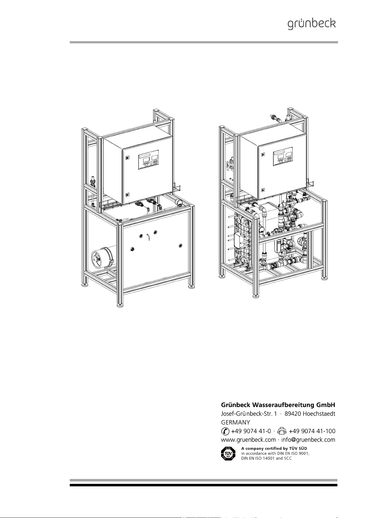
Electrodeionisation System GENO-EDI-X
with GENO-EDI-tronic
Version: December 2018
Order no. 024 770 901-inter
Page 2

Electrodeionisation System
GENO-EDI-X
Table of contents
AGENERAL INFORMATION .................................................................................................................................................................. 5
1 | P
REFACE
2 | H
3 | G
4 | S
5 | D
BBASIC INFORMATION ........................................................................................................................................................................ 9
1 | L
2 | W
3 | F
CPRODUCT DESCRIPTION (GENO-EDI-X) ........................................................................................................................................ 12
1 | T
2 | F
3 | B
4 | D
5 | T
6 | I
7 | A
8 | S
DINSTALLATION ................................................................................................................................................................................. 25
1 | G
2 | W
3 | H
4 | E
ECOMMISSIONING .............................................................................................................................................................................. 29
1 | G
2 | START EDI-X
FOPERATION ...................................................................................................................................................................................... 31
1 | I
2 | B
3 | S
4 | O
5 | O
GTROUBLESHOOTING ....................................................................................................................................................................... 56
1 | B
2| T
HMAINTENANCE ................................................................................................................................................................................. 5 8
1 | B
2 | I
3 | M
..................................................................................................................................................................................................... 5
OW TO USE THIS OPERATION MANUAL
ENERAL SAFETY INFORMATION
3.1
3.2
3.3
3.4
3.5
3.1 Functional principle of electrodeionisation ......................................................................................................................................... 10
3.2
NTENDED USE
6.1 | System shutdown ............................................................................................................................................................................ 19
8.1
8.2
8.3
1.1
1.1
NTRODUCTION
2.1
2.2
2.3
2.4
5.1
5.2
5.2.4System Configuration ............................................................................................................................................................ 37
5.2.5I/O Display ............................................................................................................................................................................... 38
5.2.6Error Memory .......................................................................................................................................................................... 38
5.2.7Basic Setting ........................................................................................................................................................................... 38
5.3
5.3.1Errors ...................................................................................................................................................................................... 3 9
5.3.2Warnings ................................................................................................................................................................................. 41
5.4
5.4.1User......................................................................................................................................................................................... 4 3
5.4.2Parameters .............................................................................................................................................................................. 43
5.4.3Times ...................................................................................................................................................................................... 46
5.4.4Errors ...................................................................................................................................................................................... 4 7
5.4.5Service Data ............................................................................................................................................................................ 50
5.4.6Reference Data ....................................................................................................................................................................... 51
5.4.7Basic Setting ........................................................................................................................................................................... 52
5.5
5.5.1User......................................................................................................................................................................................... 5 4
5.5.2Parameters .............................................................................................................................................................................. 54
5.5.3Errors ...................................................................................................................................................................................... 5 5
5.5.4Service Data ............................................................................................................................................................................ 55
5.5.5Basic Setting ........................................................................................................................................................................... 55
ROUBLESHOOTING
NSPECTION (FUNCTIONAL CHECK
3.1
Symbols and notes .................................................................................................................................................................... 6
Operating personnel .................................................................................................................................................................. 6
Designated application .............................................................................................................................................................. 6
Protection from water damage .................................................................................................................................................. 7
Description of specific dangers ................................................................................................................................................. 7
HIPPING AND STORAGE
ISPOSAL
..................................................................................................................................................................................................... 8
AWS, REGULATIONS, STANDARDS
ATER
........................................................................................................................................................................................................ 9
UNCTIONAL PRINCIPLE OF ELECTRODEIONISATION
Components of the electrodeionisation module (EDI module) ................................................................................................. 11
YPE DESIGNATION PLATE
LOW CHART DESIGN
ASIC FUNCTION OF THE ELECTRODEIONISATION SYSTEM
ESCRIPTION OF THE COMPONENTS
ECHNICAL SPECIFICATIONS
PPLICATION LIMITS
COPE OF SUPPLY
ENERAL INSTALLATION INFORMATION
ATER CONNECTION
OW TO CONNECT THE SYSTEM
LECTRICAL WIRING
ENERAL INFORMATION
RIEF DESCRIPTION OF
WITCH CABINET
PERATING THE CONTROL UNIT
PERATING THE CONTROL UNIT
ASIC INFORMATION
ASIC INFORMATION
AINTENANCE
............................................................................................................................................................................................ 1 9
...................................................................................................................................................................................... 21
Standard equipment ................................................................................................................................................................ 21
Optional features ..................................................................................................................................................................... 22
Wearing parts .......................................................................................................................................................................... 24
Preliminary work ...................................................................................................................................................................... 25
Preliminary work ...................................................................................................................................................................... 29
SYSTEM OPERATION
............................................................................................................................................................................................ 31
Field of application .................................................................................................................................................................. 31
Function .................................................................................................................................................................................. 31
Basic technical parameters – control panel ............................................................................................................................. 31
Basic technical parameters – MK200 basic module ................................................................................................................. 31
......................................................................................................................................................................................... 32
Basic information regarding the operation of the control unit ................................................................................................... 34
System menu .......................................................................................................................................................................... 34
Messages and signals ............................................................................................................................................................. 39
Electrodeionisation (GENO-EDI-X system) .............................................................................................................................. 4 2
Pressure booster (PB system) if activated in system menu ..................................................................................................... 53
............................................................................................................................................................................................ 5 9
Operation log ........................................................................................................................................................................... 59
............................................................................................................................................................ 5
..................................................................................................................................................................... 6
................................................................................................................................................................................ 7
.................................................................................................................................................................. 9
......................................................................................................................................... 10
............................................................................................................................................................................ 12
................................................................................................................................................................................... 12
.............................................................................................................................................................. 15
......................................................................................................................................................................... 18
.................................................................................................................................................................................... 20
.......................................................................................................................................................... 25
................................................................................................................................................................................... 26
.................................................................................................................................................................................... 28
.................................................................................................................................................................................... 56
..................................................................................................................................................................................... 57
.................................................................................................................................................................................... 58
.................................................................................................................................................................... 27
............................................................................................................................................................................... 29
.............................................................................................................................................................. 30
GENO-EDI-
TRONIC
.................................................................................................................................................. 31
.................................................................................................................................................................... 33
.................................................................................................................................................................... 34
) ................................................................................................................................................................ 58
GENO-EDI-X (
WITHOUT OPTIONS
) ............................................................................ 13
2
Order no. 024 770 901-inter Edited by: rreh/bkop G:\BA-770901-inter_024_GENO-EDI-X.docx
Page 3

Publisher's information
All rights reserved.
Copyright by Grünbeck Wasseraufbereitung GmbH
Printed in Germany
Effective with the date of edition indicated on the cover sheet.
-We reserve the right to modifications, especially with regard to
technical progress-
Reprints, translations into foreign languages, electronic storage
or digital copying of this operation manual – even in parts – may
take place only with explicit written approval of Grünbeck Wasseraufbereitung GmbH.
Any type of duplication not authorised by Grünbeck Wasseraufbereitung is a copyright violation and will be prosecuted.
Responsible for contents:
Grünbeck Wasseraufbereitung GmbH
Josef-Grünbeck-Straße 1 89420 Höchstädt/Do.
Phone 09074 41-0 Fax 09074 41-100
www.gruenbeck.de service@gruenbeck.de
Electrodeionisation System
GENO-EDI-X
Printing: Grünbeck Wasseraufbereitung GmbH
Josef-Grünbeck-Straße 1, 89420 Höchstädt/Do.
Order no. 024 770 901-inter Edited by: rreh/bkop G:\BA-770901-inter_024_GENO-EDI-X.docx
3
Page 4
Electrodeionisation System
GENO-EDI-X
EC Declaration of Conformity
We hereby declare that the system designated below meets the safety and health requirements
of the applicable European guidelines in terms of its design, construction and manufacture.
This certificate will become invalid if the system is modified in a way not approved by us.
Manufacturer: Grünbeck Wasseraufbereitung GmbH
Josef-Grünbeck-Str. 1
89420 Hoechstaedt/Germany
Responsible for documentation: Roland Rehberger
System designation:
System size: 100, 180, 360, 720, 1100, 1450, 2000, 2700
System number: Refer to type designation plate
Applicable directives: Machinery Directive (2006/42/EC)
Applied harmonised standards,
in particular:
Applied national standards
and technical
specifications,
in particular:
Place / Date / Manufacturer's signature:
Function of signatory: Head of Technical Systems and Equipment
Electrodeionisation system GENO-EDI-X
EMC (2014/30/EU)
EN ISO 12100:2011-03,
EN 61000-6-2:2006-03
EN 61000-6-3:2011-09
Höchstädt, 2018-10-11 p.p.a.
P. Höß
4
Order no. 024 770 901-inter Edited by: rreh/bkop G:\BA-770901-inter_024_GENO-EDI-X.docx
Page 5
A General information
Electrodeionisation System
GENO-EDI-X
1 | Preface
Thank you for opting for a Grünbeck product. Backed by
Advice and assistance
decades of experience in the area of water treatment, we
provide solutions for all kind of processes.
All Grünbeck systems and devices are made of high-quality
materials. This ensures trouble-free operation over many years,
provided you treat your water treatment system with the required
care. This operation manual assists you with important
information. Therefore, please read the entire operation manual
before installing, operating or maintaining the system.
Customer satisfaction is our prime objective and providing
customers with qualified advice is crucial. If you have any
questions concerning this device, possible extensions or general
water and waste water treatment, our field service staff, as well
as the experts at our headquarters in Hoechstaedt, are available
to help you.
For advice and assistance please contact your local
representative (refer to www.gruenbeck.de).
In case of emergency, please get in touch with our service hotline at +49 9074 41-333. We can connect you with the appropriate expert more quickly if you provide the required system data.
To ensure that this information is to hand at all times, please
keep the precise equipment data to hand (refer to the type plate
in chapter C-1).
2 | How to use this operation manual
This operation manual is intended for the operators of our sys-
tems. It is divided into several chapters (a letter is assigned to
each of them) which are listed in the table of contents on page 2
in alphabetical order. Check for the corresponding chapter on
page 1 in order to find the specific information you need.
The headers and page numbers with chapter information make it
easier to find your way around in the operation manual.
Order no. 024 770 901-inter Edited by: rreh/bkop G:\BA-770901-inter_024_GENO-EDI-X.docx
5
Page 6
Electrodeionisation System
GENO-EDI-X
3 | General safety information
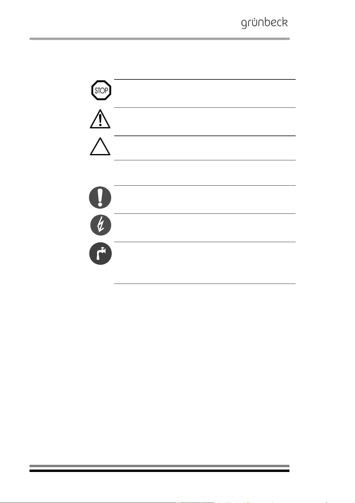
3.1 Symbols and notes
Important information in this operation manual is emphasised by
symbols. Please pay particular attention to this information to
ensure the hazard-free and safe handling of the system.
Danger! Failure to adhere to this information will cause serious or
life-threatening injuries, extreme damage to property or
inadmissible contamination of the drinking water.
Warning! Failure to adhere to this information may cause
injuries, damage to property or contamination of the drinking
water.
Caution! Failure to adhere to this information may result in
damage to the system or other objects.
Note: This symbol emphasises information and tips that make your
work easier.
Tasks with this symbol may only be performed by Grünbeck's
technical service/authorised service company or by persons
expressly authorised by Grünbeck.
Tasks with this symbol may only be performed by trained and qualified electrical experts according to the VDE guidelines or according
to the guidelines of a similar local institution.
Tasks with this symbol may only be performed by water
suppliers or approved installation companies. In Germany, the
installation company must be registered in an installation
directory of a water supplier as per §12(2) AVBWasserV
(German Ordinance on General Conditions for the Supply of Water).
3.2 Operating personnel
3.3 Designated application
Only persons who have read and understood this operation
manual are permitted to work with the system. Strictly observe
the safety information.
The system may only be used for the purpose outlined in the
product description (chapter C). The guidelines in this operation
manual as well as the applicable local guidelines concerning
drinking water protection, accident prevention and occupational
safety must be observed.
In addition, intended use also implies that the system may only
be operated when it is in proper working order.
Any errors must be eliminated at once.
The GENO-EDI-X is exclusively designed for use in the industrial and commercial field.
6
Order no. 024 770 901-inter Edited by: rreh/bkop G:\BA-770901-inter_024_GENO-EDI-X.docx
Page 7
3.4 Protection from water
damage
3.5 Description of
specific dangers
Electrodeionisation System
GENO-EDI-X
Warning! In order to properly protect the installation site against
water damage:
A sufficiently dimensioned floor drain system must be
available or
a water stop device (refer to chapter C “Accessories”) must
be installed.
Warning! Floor drains that discharge to a lifting system will not
work in case of a power failure.
Danger due to electrical energy! Do not touch electrical parts
with wet hands! Disconnect the system from the mains before
starting work on electrical system components. Have qualified
experts replace damaged cables immediately.
Danger due to mechanical energy! System components may be
subject to overpressure. Danger of injury and damage to
property due to escaping water and unexpected movement of
system components. Check pressure pipes regularly.
Depressurise the system before starting repair or maintenance
work on the system.
Hazardous to health due to contaminated drinking water! The
system shall be installed only by a specialist company. Strictly
observe the operation manual! Ensure that there is sufficient
flow; the relevant guidelines must be followed for commissioning
after extended periods of standstill. Inspections and
maintenance must be performed at the intervals specified!
Note: By concluding a maintenance contract, you ensure that all
of the required tasks are performed on time. You may perform
the interim inspections yourself.
4 | Shipping and storage
Caution! The system may be damaged by frost or high
temperatures. In order to avoid damage of this kind:
Protect from frost during transportation and storage!
Do not install or store the system next to objects which radiate a
lot of heat.
The system may only be transported and stored in its original
packing. Ensure that it is handled with care and placed the right
side up (as indicated on the packaging).
Order no. 024 770 901-inter Edited by: rreh/bkop G:\BA-770901-inter_024_GENO-EDI-X.docx
7
Page 8

Electrodeionisation System
GENO-EDI-X
5 | Disposal
Comply with the applicable national regulations.
5.1 Packaging
5.2 Product
Dispose of the packaging in an environmentally friendly manner.
If this symbol (crossed out waste bin) is on the product, this
product is subject to the European Directive 2012/19/EU. This
means that this product or the electrical and electronic components must not be disposed with household waste.
Learn about the local regulations on the separate collection of
electrical and electronic products.
For information on collection points for your product, contact
your municipality, the public waste management authority, an
authorised body for the disposal of electrical and electronic products or your waste disposal service.
8
Order no. 024 770 901-inter Edited by: rreh/bkop G:\BA-770901-inter_024_GENO-EDI-X.docx
Page 9

Electrodeionisation System
GENO-EDI-X
B Basic information
1 | Laws, regulations, standards
In the interest of good health, rules cannot be ignored when it
comes to the processing of drinking water. This operation
manual takes into consideration the current guidelines and
stipulates information that you will need for the safe operation of
your water treatment system.
Among other things, the set of rules stipulate that
only approved specialist companies are permitted to make
major modifications to water supply systems
and that tests, inspections and maintenance on installed
devices are to be performed at regular intervals.
2 | Water
As a result of dynamic substance and water cycles, increasingly
polluting elements are being released into the natural
environment. These are only partially and slowly broken down by
natural effects. Consequently, these elements build up in the
groundwater and surface water over the course of time.
Removing them from natural water deposits again represents a
particular challenge. Grünbeck faces this challenge with the
aim of producing unpolluted drinking and industrial water.
Order no. 024 770 901-inter Edited by: rreh/bkop G:\BA-770901-inter_024_GENO-EDI-X.docx
9
Page 10

Electrodeionisation System
GENO-EDI-X
3 | Functional principle of electrodeionisation
3.1 Functional principle of electrodeionisation
Function
The electrodeionisation represents a continuous, electrochemical
membrane process that combines membrane technology and ion
exchanger technology.
In this process, ion exchanger resin, ion-selective membranes
and direct current are used to remove ions from the permeate of
a reverse osmosis system.
The resulting diluate (ultra-pure water) has a residual
conductivity of < 0.2 µS/cm. The residual conductivity depends
on the quality of the feed water (permeate).
The advantage of this technology is the fact that the
regeneration (by means of direct current) continuously takes
place during operation and no chemicals (acids/bases) are
required.
Contrary to common ion exchanger systems, the
electrodeionisation system GENO-EDI-X considerably
reduces the TOC values.
The core – the EDI module – consists of several chambers filled
with layers of anion and cation exchanger resins. The chambers
are separated from each other by anion and cation membranes.
The feed water (permeate) flows into the EDI module and is
divided into a diluate, concentrate and electrolyte water flow.
Due to the direct voltage applied, the ions move from the
diluate chambers filled with ion exchanger resin to the
concentrate chambers that are also filled with ion exchanger
resin.
While the water is in the diluate chambers is being fully
demineralised, the direct current splits the water into hydrogen
ions (H+) and hydroxide ions (OH
exchanger resins are regenerated again.
A part (10 %) of the feed water volume (permeate) rinses the
concentrate and the electrode chambers. The volume
designated as concentrate (unpressurised) is then either
directed to the drain or returned to the inlet of the reverse
osmosis system to be fed again.
The electrodeionisation system GENO-EDI-X has a recovery of
90 - 95 %.
-
) by which in turn the ion
10
Order no. 024 770 901-inter Edited by: rreh/bkop G:\BA-770901-inter_024_GENO-EDI-X.docx
Page 11
Electrodeionisation System
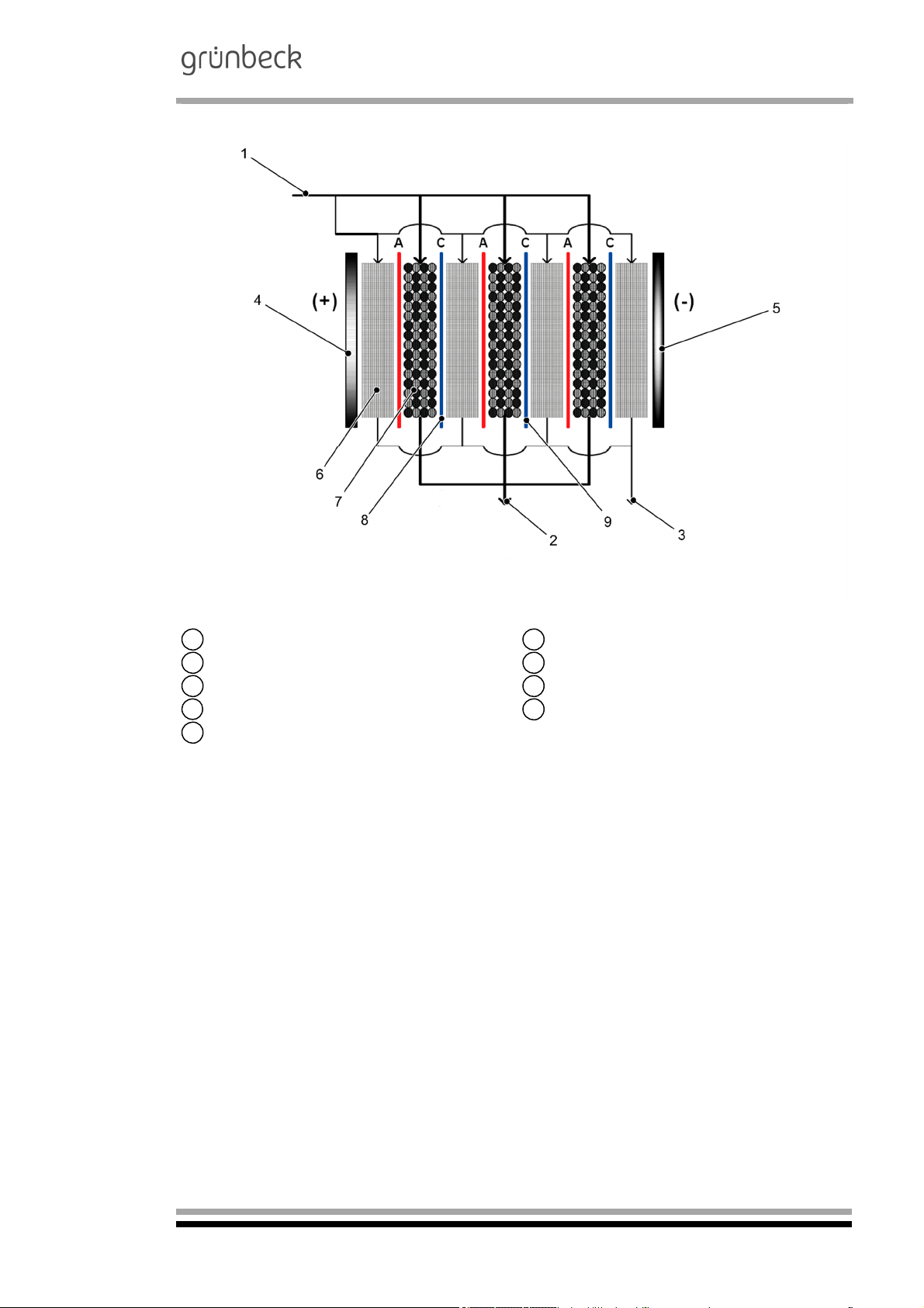
3.2 Components of the electrodeionisation module (EDI module)
GENO-EDI-X
Permeate inlet Diluate outlet
1 2
Concentrate outlet
3 4
Cathode (-)
5 6
Diluate chamber with ion exchanger resin
7
Cation membrane (C)
9
Anode (+)
Concentrate chamber with ion exchanger resin
Anion membrane (A)
8
Order no. 024 770 901-inter Edited by: rreh/bkop G:\BA-770901-inter_024_GENO-EDI-X.docx
11
Page 12
Electrodeionisation System
GENO-EDI-X
C Product description (GENO-EDI-X)
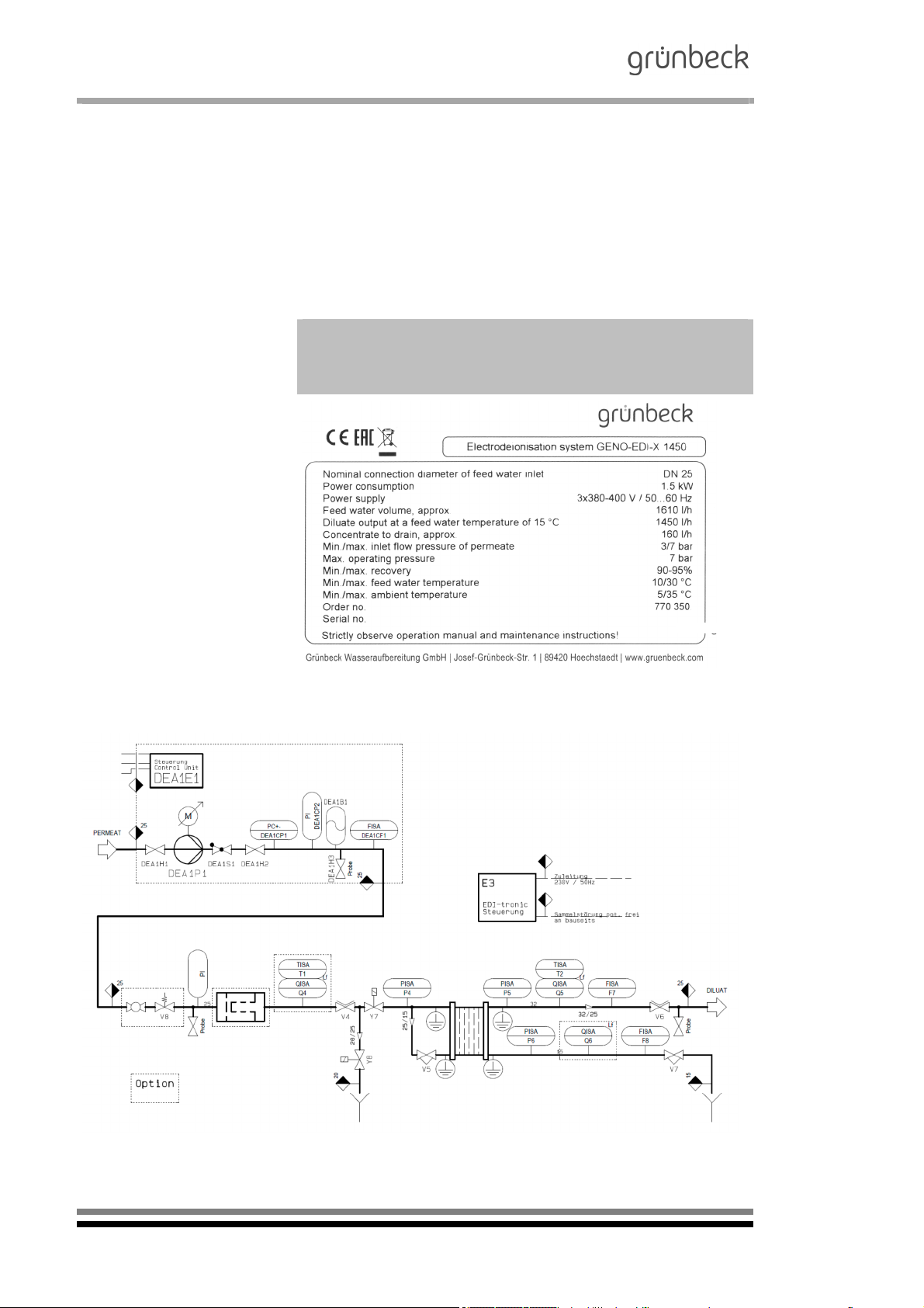
1 | Type designation
plate
Please specify the data shown on the type designation plate of
your GENO-EDI-X electrodeionisation system in order to speed
up the processing of enquiries or orders. Please add the
necessary information to the overview below to have it readily
available whenever necessary.
Electrodeionisation system GENO-EDI-X:
Serial number:
Order number:
2 | Flow chart design
Fig. C-1: Type designation plate of the electrodeionisation system GENO-EDI-X
Fig. C-2: Flow chart of GENO-EDI-X
Order no. 024 770 901-inter Edited by: rreh/bkop G:\BA-770901-inter_024_GENO-EDI-X.docx
12
Page 13

Electrodeionisation System
GENO-EDI-X
3 | Basic function of the electrodeionisation system GENO-EDI-X
(without options)
If the system is in standby mode and ready for operation, the
inlet rejection valve and the inlet valve are closed. There is no
voltage present at the EDI module. If available, the outlet
rejection valve is open and the outlet valve closed. The
electrodeionisation system receives its start signal from the level
control system of the diluate tank. Then, the EDI controller
transmits the start signal to the RO controller. The RO system
starts operation and produces permeate. By means of the inlet
rejection valve, the time-controlled discharge of the permeate to
the drain takes place. In case the conductivity measuring cell for
permeate is installed, the rejection can be terminated prematurely if the max. permeate conductivity set is undershot.
Upon termination of the inlet rejection, the inlet valve opens and
the inlet rejection valve closes. When the inlet valve opens, the
EDI cell is supplied with voltage. From the moment the inlet
valve opens, the flows diluate and concentrate, the diluate
conductivity, the pressure of permeate, diluate and concentrate
as well as the temperature and the diluate are monitored and
trigger a time-delayed (adjustable) warning or an alarm. The
diluate is rejected via time by means of the outlet rejection - if
available (option) -, with premature termination in case the max.
diluate conductivity set is undershot. Following the opening of
the outlet valve, the outlet rejection valve is closed. The diluate
produced is now directed to the diluate tank.
As soon as the tank is full, a stop signal is transmitted to the EDI
controller. Within the electrodeionisation system, the voltage
supplied to the EDI cell is interrupted and the monitoring function
of the EDI system is deactivated. After a set rinsing sequence,
the RO system receives its stop signal and the valves move to
the following positions: Inlet rejection valve and inlet valve close
and – if available – the outlet rejection valve is open and the outlet vale is closed. Now, the electrodeionisation system remains
in standby mode until the next demand is made.
If the system is in standby mode, the inlet rejection valve Y8 and
the inlet valve Y7 are closed. There is no voltage present at the
EDI module.
The GENO-EDI-X system receives a start signal from the level
control system of the diluate tank. Then, the EDI controller transmits the start signal to the RO controller.
The RO system starts operation and produces permeate. By
means of the inlet rejection valve Y8, the discharge of the permeate to the drain takes place over a pre-set time period. Upon
termination of the inlet rejection, the inlet valve Y7 opens and the
inlet rejection valve Y8 closes.
When the inlet valve Y7 opens, the EDI module is supplied with
the divided partial permeate flows of diluate and concentrate.
In addition, the voltage and current are switched to the EDI module.
Order no. 024 770 901-inter Edited by: rreh/bkop G:\BA-770901-inter_024_GENO-EDI-X.docx
13
Page 14

Electrodeionisation System
GENO-EDI-X
From the moment the inlet valve Y7 opens, the diluate F7 and
concentrate F8 flows, the diluate conductivity Q5, the pressure
of permeate P4, diluate P5 and concentrate P6, as well as the
temperature of the diluate T2 are monitored and trigger a timedelayed (adjustable) warning and/or an error.
The diluate produced is now directed to the diluate tank. As soon
as the tank is full, a stop signal is transmitted to the EDI controler. Within the GENO-EDI-X electrodeionisation system, the
voltage supplied to the EDI cell is interrupted and the monitoring
function of the GENO-EDI-X system is deactivated.
After a set rinsing sequence, the RO system receives its stop
signal and the valves move to the following positions: inlet rejection valve Y8 and inlet valve Y7 closed.
Now, the GENO-EDI-X system remains in standby mode until
the next request is made.
*Diluate = deionate, ultra-pure water
14
Order no. 024 770 901-inter Edited by: rreh/bkop G:\BA-770901-inter_024_GENO-EDI-X.docx
Page 15
4 | Description of the components
Electrodeionisation System
GENO-EDI-X
Adjusting valve
Operating
V4
1
2
3
4
5
6
7
pressure
(OPTION)
Adjusting valve
V5
Concentrate
volume
Adjusting valve
V6
Diluate pressure
Adjusting valve
V7
Concentrate
pressure
Permeate
V8
overflow valve
(OPTION)
Sample valve of
Pr-P
feed water
(Permeate)
Sample valve of
Pr-D
diluate
To throttle the permeate supply flow in case of excess capacity
from on-site feed pumps.
Not required for agreed-upon RO/EDI system combinations.
For the adjustment of the concentrate volume conducted to the
drain. This value corresponds with 10% of the permeate feed
value.
For the adjustment of the diluate counter-pressure.
For the adjustment of the concentrate pressure to the diluate
pressure.
Conducts the permeate from upstream RO systems to the drain;
these systems work in forced operation mode.
Protects the permeate side of the RO system in case the
solenoid valves of the GENO-EDI-X system do not open.
Adjustment: OPEN at 4 bar (g).
Possibilities of manual quality determination
via sample valve.
Possibilities of manual quality determination
via sample valve.
10
11
Registers the permeate quantity and sends pulses to the control
electronics.
8
9
diluate
Flow sensor
F8
Concentrate
Permeate
P4
pressure sensor
Pressure sensor
P5
Diluate
Flow sensor of
F7
Visual indication of the diluate quantity in the control electronics.
If the minimum flow of the diluate is undershot, an error is emitted.
GENO-EDI-X system STOP
Registers the concentrate volume and sends pulses to
the control electronics.
Visual indication of the concentrate volume in the control
electronics. If the minimum flow of the concentrate is undershot,
an error is emitted.
GENO-EDI-X system STOP
The maximum limit value is 4 bar(g)
When the set maximum permeate pressure value is exceeded,
the GENO-EDI-X system STOP takes place with a time delay.
Visual indication in the control electronics.
Indicates the diluate pressure value in the control electronics.
P5 must be at least 0.2 bar higher than P6!
The alarm signal takes place with a time delay when the
concentrate pressure value P6 is higher than/equal to the diluate
pressure value P5.
GENO-EDI-X system STOP
Order no. 024 770 901-inter Edited by: rreh/bkop G:\BA-770901-inter_024_GENO-EDI-X.docx
15
Page 16
Electrodeionisation System
GENO-EDI-X
Indicates the concentrate pressure in the control electronics.
P5 must be at least 0.2 bar higher than P6!
The alarm signal takes place with a time delay when the
concentrate pressure value P6 is higher than/equal to the diluate
pressure value P5.
GENO-EDI-X system STOP
Always open during diluate production.
Opens after a settable time interval (permeate rejection). Opens
after inlet rejection at conductivity < 20 µS/cm measured via Q4
(option).
Locked in case of errors in the GENO-EDI-X system.
Visual indication in the control electronics.
Opens for an adjustable time after EDI start.
Opens after start of EDI until a conductivity of 20 µS/cm measured via Q4 is undershot (option).
Closes after inlet rejection. Visual indication in the control
electronics.
12
13
14
Concentrate
P6
pressure sensor
Inlet solenoid
Y7
valve of permeate
Permeate inlet re-
Y8
jection valve
15
16
17
18
Outlet solenoid
valve of diluate
Y9
(OPTION)
Outlet rejection
valve of diluate
Y10
(OPTION)
Conductivity
measuring cell of
Q4
permeate
(OPTION)
Conductivity
Q5
measuring cell of
diluate
Opens after diluate rejection from Y10 if the conductivity limit
value for diluate is undershot.
Closes after GENO-EDI-X system STOP, locked in case of
errors in the GENO-EDI-X system.
Visual indication in the control electronics.
Opens after GENO-EDI-X system START and completed inlet
rejection, closes when the conductivity limit value for diluate is
undershot.
Visual indication in control electronics.
Indicates the quality of the permeate in the control electronics.
Enables quality-controlled permeate rejection.
Y8 CLOSED and Y7 OPEN if the set conductivity limit value
is undershot.
Visual alarm signal in the control electronics when the set conductivity limit value is exceeded.
GENO-EDI-X system STOP.
Indicates the quality of the diluate in the control electronics.
Enables quality-controlled diluate rejection.
Y10 CLOSED and Y9 OPEN if the set conductivity limit value is
undershot.
Visual alarm signal in the control electronics when the set conductivity limit value is exceeded.
GENO-EDI-X system STOP.
19
20
16
Conductivity
measuring cell
Q6
Concentrate
(OPTION)
Permeate temperature sensor
T1
(OPTION)
Order no. 024 770 901-inter Edited by: rreh/bkop G:\BA-770901-inter_024_GENO-EDI-X.docx
Indicates the quality of the concentrate in the control electronics.
Indicates the temperature of the permeate in the control electronics.
Y8 CLOSED and Y7 OPEN if the set temperature value is exceeded.
Visual alarm signal in the control electronics when the set limit
value is exceeded.
GENO-EDI-X system STOP.
Page 17
Electrodeionisation System
GENO-EDI-X
Indicates the temperature of the diluate in the control electronics.
21
22
23
Diluate
temperature
T2
sensor
(OPTION)
Permeate feed
M8/
pump
P8/
Frequencycontrolled
P9
(OPTION)
Level control
L4
system of diluate
tank
Y9 CLOSED and Y10 OPEN if the set temperature value
is exceeded.
Visual alarm signal in the control electronics when the set limit
value is exceeded.
GENO-EDI-X system STOP.
Increases the permeate feed pressure.
Permeate pump M8 START through min. pressure contact P8.
Permeate pump M8 STOP through max. pressure contact P8.
Alternatively, M8 is operated using pressure sensor P8 in a
frequency-controlled manner.
M8 release always provided in case of inlet valve Y7 OPEN.
M8 is locked in case of min. pressure switch P9 (min. pressure).
Visual alarm signal on the frequency converter and in the
control electronics.
GENO-EDI-X system STOP.
Visual indication in the control electronics.
L4a+ full signal, GENO-EDI-X system STOP
L4b- request, GENO-EDI-X system START
L4c- additional and emergency feed (option)
L4d+ empty signal, dry-run protection for
PBS pump M6/M7, time-delayed
release for PBS pump M6/M7 in case level is exceeded
Visual indication in the control electronics.
Actuated by the pre-selector (H-O-A) in the control electronics.
Pressure booster
M6/
system
M7/
Diluate pressure
switch
P7
(OPTION)
Pressure switch with min. and max. pressure contact.
In case of automatic operation:
- M6/M7 ON via min. pressure contact of P7
- M6/M7 OFF via max. pressure contact of P7
- Time-controlled changeover operation of pumps M6/M7.
M6/M7 re locked in case of dry-run protection L4d.
Visual alarm signal in control electronics.
Order no. 024 770 901-inter Edited by: rreh/bkop G:\BA-770901-inter_024_GENO-EDI-X.docx
17
Page 18

Electrodeionisation System
GENO-EDI-X
5 | Technical specifications
Table C-1: Technical
Electrodeionisation system GENO-EDI-X
specifications
100 180 360 720 1100 1450 2000 2700
Connection data
Nominal connection diameter of
permeate feed line (screw connection)
Nominal connection diameter of
diluate outlet line (screw connection)
Nominal connection diameter of
concentrate outlet line
(screw connection)
Min. drain connection required [DN] 50
Connected load, approx.
Power supply [V/Hz] 1x 230 / 50
Protection type IP 54
Performance data
Feed water volume flow
(nominal)
Diluate capacity at a feed water
temperature 15°C and
a recovery of approx. 90 % (nominal)
Concentrate volume flow at
a recovery of approx. 90% (nominal)
Diluate capacity max.**** [l/h] 150 300 600 1000 1350 2100 2600 3750
Min. diluate flow*** required [l/h] 62,5 125 250 550 550 1100 1100 1400
Min. required flow of
concentrate***
Operating voltage [V-DC] < 106 < 213 < 426 < 130 < 130 < 240 < 240 < 300
Operating current [A] < 2.5 < 2.5 < 2.5 < 5 < 5 < 5 < 5 < 5
Inlet flow pressure of permeate,
min./max.
Outlet pressure of diluate, approx. [bar] 0.5/1.5
Max. operating pressure
Feed conductivity equivalent (FCE)**,
max.
Diluate conductivity*
TOC reduction
SiO2 reduction
Recovery***
Dimensions and weights
Dimensions (w x h x d) [mm] 900 x 1700 x 675
Min. room/installation height required [mm] 2000
Operating weight, approx. [kg] 95 105 115 170 170 190 190 215
Ambient data
Temperature of feed water, min./max. [°C] 10/25
Ambient temperature, min./max. [°C] 5/35
Order no. 770 300 770 310 770 320 770 330 770 340 770 350 770 360 770 370
*
Subject to the feed water quality
** For calculation, refer to the formula under “Application limits”
*** These volume flows must be considered as the absolute minimum for the flow rates of the EDI module!
**** In case of maximum recoveries of 93 and/or 95 %, the following shall further apply with regard to the feed water
specification:
< 0.02 ppm and SiO2 < 0.5 ppm
CaCO
3
[DN] 15 25
[DN] 15 25
[DN] 15 15
0.5 1.0 1.5 1.0 1.0 1.5 1.5 1.5
[kW]
[l/h]
110 200 400 800 1200 1600 2200 3000
[l/h] 100 180 360 720 1100 1450 2000 2700
[l/h] 10 20 40 80 100 150 200 300
[l/h] 10 20 40 40 40 65 65 85
[bar] 2/5 3/7
bar OP] 5 7
[µS/cm] 40
[µS/cm]
< 0.2
60 - 80
90 - 99
90 - 93 90 - 95
18
Order no. 024 770 901-inter Edited by: rreh/bkop G:\BA-770901-inter_024_GENO-EDI-X.docx
Page 19

Electrodeionisation System
GENO-EDI-X
6 | Intended use
The electrodeionisation system GENO-EDI-X is designed for the
further quality enhancement of permeate generated by a
reverse osmosis system.
The most common areas of application for the diluate produced
(ultra-pure water) are:
- Steam sterilisation
- Semi-conductor industry
- Generation of pure steam
- Laboratories
The system can be used only after a prior water analysis and
corresponding pretreatment.
The continuous diluate output of the system is subject to the
temperature and is defined at 15°C. The diluate outputs can fall
(falling temperature) or rise (rising temperature) by up to 3 % for
each °C the raw water temperature increases or decreases.
Only operate the system if all components are properly installed.
Safety devices must NEVER be removed, bridged or otherwise
tampered with.
Appropriate application of the device also implies that the
information contained in this operation manual and all safety
regulations applying at the installation site be observed.
Furthermore, the maintenance and inspection intervals have to
be observed.
6.1 | System shutdown
During decommissioning of the GENO-EDI-X system, the
necessary measures must be decided upon together with
Grünbeck’s technical service.
Order no. 024 770 901-inter Edited by: rreh/bkop G:\BA-770901-inter_024_GENO-EDI-X.docx
19
Page 20

Electrodeionisation System
GENO-EDI-X
7 | Application limits
Conductivity equivalent
FCE*: < 40 µS/cm
(CO
included)
2
Range of pH value: 4 – 11
Cl
concentration: < 0.02 ppm
2
Fe concentration: < 0.01 ppm
Mn concentration: < 0.01 ppm
Sulphide concentration: < 0.01 ppm
Concentration of residual
hardness (CaCO
(^ 0.056 °dH)
TOC concentration < 0.5 ppm
Silicate concentration (SiO
Water temperature: 10 – 25°C
*FCE = permeate conductivity + (ppm CO
+ (ppm SiO
): < 1.0 ppm
3
x 1.94)
2
): < 1.0 ppm
2
x 2.79)
2
Note: The diluate from GENO-EDI-X system is not drinking
water!
*
For the determination of this value, the formulae in section E,
chapter 1 must be used!
20
Order no. 024 770 901-inter Edited by: rreh/bkop G:\BA-770901-inter_024_GENO-EDI-X.docx
Page 21

8 | Scope of supply
Electrodeionisation System
GENO-EDI-X
8.1 Standard equipment
Device that is ready for connection for the continuous,
electrochemical, residual demineralisation of permeate
originating from a reverse osmosis system, completely
pre-assembled to an anodised aluminium system rack.
Microprocessor controller with LCD graphic display
(70 x 38 mm backlit) Flow chart of the electrodeionisation
system with collection tank including level control, pressure
booster system for diluate as well as indication of the flow,
pressure and conductivity values of the electrodeionisation
system.
Version: Membrane keyboard with 12 buttons and serial
interface RS 232, system piping within the
electrodeionisation system equipped with pressure sensors,
adjusting and/or solenoid valves, as well as sampling fittings.
Integrated flow sensors to monitor the volume flows diluate
and concentrate. The switch cabinet features all power units
as well as the control electronics. Quality assurance of
diluate by means of temperature-compensated conductivity
measurement with digital indication at the display of the
control electronics Piping within the system completely made
of high-pressure resistant PE plastic pipes.
EDI module as the main core of process engineering.
Installation and operation manual.
Order no. 024 770 901-inter Edited by: rreh/bkop G:\BA-770901-inter_024_GENO-EDI-X.docx
21
Page 22

Electrodeionisation System
GENO-EDI-X
8.2 Optional features
Note: It is possible to retrofit existing systems with optional
components. Please contact your local Grünbeck field service
staff or Grünbeck’s headquarters in Hoechstaedt for more
information.
GENO-EDI-Profibus DP
Module to provide system data
770 860
For GENO-EDI-X 100 through 360 770 815
For GENO-EDI-X 720 through 2700 770 875
For GENO-EDI-X 720 through 2700
GENO-EDI voltage-free single fault signals
for DDC/central building and control system
Module for single fault signals (voltage-free) to
control centre
Quality-controlled permeate rejection
Rejection of feed permeate in the inlet to the
electrodeionisation system
(conductivity-controlled)
Analogue outputs (4-20 mA) for conductivity
and diluate temperature
Module for outputting measuring values to control
centre
Quality-controlled diluate rejection
Rejection of diluate prior to filling
the pure water tank (conductivity-controlled)
Measuring of conductivity and temperature of
EDI concentrate
Module to measure the conductivity / temperature
in the EDI concentrate (waste water)
in the feed water
For GENO-EDI-X 100 through 360
GENO membrane degassing system
MEC 500-1 (single-stage)
For removing CO
of the electrodeionisation system
Flow volume of feed water:
0.1 – 0.7 m³/h
Amount of stripping gas* required:
0.2 – 1.8 Nm³/h
GENO membrane degassing system
MEC 500-2 (2-stage)
For removing CO
of the electrodeionisation system
Flow volume of feed water:
0.1 – 0.7 m³/h
Amount of stripping gas* required:
0.4 – 3.6 Nm³/h
from the feed water (permeate)
2
from the feed water (permeate)
2
770 855
770 800
770 810
770 805
770 870
770 200
770 205
22
Order no. 024 770 901-inter Edited by: rreh/bkop G:\BA-770901-inter_024_GENO-EDI-X.docx
Page 23

Electrodeionisation System
GENO-EDI-X
GENO membrane degassing system
MEC 2200-1 (single-stage)
For removing CO
from the feed water (permeate)
2
of the electrodeionisation system
Flow volume of feed water:
0.5 – 3.41 m³/h
Amount of stripping gas* required:
0.8 – 5.1 Nm³/h
GENO membrane degassing system
MEC 2200-2 (two-stage)
For removing CO
from the feed water (permeate)
2
of the electrodeionisation system
Flow volume of feed water:
0.5 – 3.41 m³/h
Amount of stripping gas* required:
1.6 – 10.2 Nm³/h
*Stripping gas = oil-free, compressed air
Pure water tank for intermediate storage of the
diluate flowing unpressurised from the
GENO-EDI-X electrodeionisation systems
Tank version:
All tanks are pre-assembled, with PVC overflow pipe as
well as connections for the inlet, diluate and the suction
line of the pressure booster system. Grey PE. Hand-hole
with removable screw cap. Level probe for installation
into the tank, electrically connected to GENO-EDI-tronic
controller.
Basic clean water tank X
RT 1000 with sterile filter and level measuring probe
Net volume approx. 850 litres
L 780 / W 990 / total H 2000 mm
1)
.
770 210
770 215
712
480
Additional tank RT for basic pure water tank
Net volume approx. 850 litres
L 780 / W 780 / total H 2100 mm
1)
Tank height including connecting pieces.
1)
.
For larger tanks, please inquire
Additional tank without level control and overflow loop,
including 2 connecting lines, id=36 mm.
Note: A maximum of four supply tanks can be combined.
For larger CO
Order no. 024 770 901-inter Edited by: rreh/bkop G:\BA-770901-inter_024_GENO-EDI-X.docx
trap for pure water tank
CO
2
For the removal of free carbon dioxide from the tank's
ventilating air.
traps, please inquire
2
712
405
712 800
23
Page 24

Electrodeionisation System
GENO-EDI-X
Pressure booster system
GENO-FU-X 2/40-1 NE
Compact, pressure-controlled pump aggregate
consisting of a centrifugal pump completely made of
stainless steel as well as an integrated pressure and
flow meter for pump control and dry-run protection.
Special version for the delivery of diluate.
Delivery rate: Max. 1.2 - 4.4 m³/h
Delivery head: max. 26.7 - 59.4 m
730 790
Power supply: 230 V / 50 Hz
Power consumption: 1.07 kW
Connections: DN 25 / 1”
Protection type: IP 55
For larger systems, please inquire
8.3 Wearing parts
Seals and valves are subject to a certain wear and tear. Wearing
Pressure booster system
GENO-FU-X 2/40-2 NE
Description as for single pressure booster system,
however, with the possibility for time-load switch-over.
parts are listed below.
Note: Although these parts are wearing parts, we grant a limited
warranty period of 6 months. The same applies to electrical components.
Solenoid valves, adjusting valves (operating pressure, concentrate volume, concentrate pressure, diluate pressure), sample
valves and water meters
730 791
24
Order no. 024 770 901-inter Edited by: rreh/bkop G:\BA-770901-inter_024_GENO-EDI-X.docx
Page 25

Electrodeionisation System
GENO-EDI-X
D Installation
1 | General installation information
The installation site must offer adequate space. For installation
and service work, sufficient clearance (> 50 cm, > 20 cm from
the wall) must be provided around the system. A foundation of a
sufficient size and adequate load carrying capacity must be provided.
The required connections must be provided prior to the installation of the system. For dimensions and connection data, please
refer to the table "Technical specifications".
The installation of an electrodeionisation system represents a
major interference with the drinking water system. Therefore,
only approved installation companies may install such systems.
Observe local installation guidelines and general regulations.
Install a drinking water filter upstream (e.g., pureliQ).
Install a system separator upstream.
Install a water softener upstream.
1.1 Preliminary work
Install an activated carbon filter upstream.
Install a reverse osmosis system upstream If the CO
tion is too high, a membrane degassing system must be provided in addition.
Provide a drain connection (at least DN 50) to discharge the
concentrate.
For the electrical connection, a feed line to the system must be
provided on site according to the electric circuit diagram. This
line must be dimensioned according to the system type.
The installation site must have a floor drain. If no floor drain is
available, an adequate safety device needs to be installed. Floor
drains that discharge to a lifting system will not work in case of a
power failure.
Safe unloading/placing of the system.
Unpacking of the system/system components.
Check of the system for any damage.
Erection of the electrodeionisation system.
Check of the mechanical and electrical connections; these
connections might have to be retightened after transport.
concentra-
2
Note: When installing systems with optional features, also
Order no. 024 770 901-inter Edited by: rreh/bkop G:\BA-770901-inter_024_GENO-EDI-X.docx
observe any additional operation manuals.
25
Page 26

Electrodeionisation System
GENO-EDI-X
2 | Water connection
Certain binding rules must always be observed when installing
the electrodeionisation system. Additional recommendations are
given in order to facilitate the handling of the system.
Mandatory regulations
The installation of the electrodeionisation system may be
performed by an approved installation company only.
Observe local installation guidelines and general
regulations.
Establish the feed water connection (permeate).
Establish the concentrate connection.
Guarantee free access to the drain!
Establish the diluate connection.
Testing of the tightening torques on the bolts of the
EDI module
Tighten any bolts according to specification.
Applies to: GENO-EDI-X 720 / 1100 / 1450 / 2000 / 2700.
Provide a drain connection (minimum DN 50) to
discharge the concentrate.
Note: If the concentrate is directed to a lifting system, the
delivery rate of the lifting system must be > 500 l/h.
Warning! At the installation site, you must ensure that the
depressurised waste water can flow off to the drain without
obstruction.
Warning! The installation site must have an adequate exchange
of air!
26
Order no. 024 770 901-inter Edited by: rreh/bkop G:\BA-770901-inter_024_GENO-EDI-X.docx
Page 27

3 | How to connect the system
Remove the protective caps from system’s feed water (= per-
meate), diluate and concentrate-to-drain connections
Connect the feed water (= permeate).
Connect the concentrate to drain according to DIN 1988.
Establish the connection between diluate outlet and diluate
tank.
Electrodeionisation System
GENO-EDI-X
Mount CO
Limit of supply
Grünbeck
by others
Raw water
Diluate
Concentrate
Fig. D-1: Installation drawing
1
Drinking water filter BOXER K 1"
System separator DK 2
2
Delta-p water softener
3
4
GENO-softwatch Komfort
Activated carbon filter AKF
5
trap to vent the diluate tank
2
Reverse osmosis system GENO-OSMO-X
6
Electrodeionisation system GENO-EDI-X
7
(Optionally with integrated GENO membrane
degassing system MEC)
8
Diluate tank with CO2 trap
9
Pressure booster system GENO-FU-X
Note: In the feed water (= permeate), concentrate and diluate
pipes provided by others on site, separable connections must be
present (e.g. screw connections) to be able to separate the
pipes.
Note: The feed water (= permeate), diluate and concentrate
pipes have to be made of corrosion-proof material.
Order no. 024 770 901-inter Edited by: rreh/bkop G:\BA-770901-inter_024_GENO-EDI-X.docx
27
Page 28

Electrodeionisation System
GENO-EDI-X
4 | Electrical wiring
Note: The pertinent electric circuit diagrams are located
separately in the switch cabinet of the GENO-EDI-X system. The
power feed line dimensions can be found there.
1. For the electrical connection, a supply line to the system
must be provided on site according to the electric circuit
diagram. This line must be dimensioned according to the
system type.
2. Wire the level control of the collection tank according to the
electric circuit diagram.
3. Testing of the earth connections of the EDI module
Each of the 4 connection pieces on the EDI module must
4. Any connection of a collective fault signal must take place
on site.
be earthed!
28
Order no. 024 770 901-inter Edited by: rreh/bkop G:\BA-770901-inter_024_GENO-EDI-X.docx
Page 29

K
Electrodeionisation System
GENO-EDI-X
E Commissioning
The work described below may only be performed by trained
experts. For safety reasons, the commissioning must be
performed by Grünbeck's trained and authorised technical
customer service/authorised service company.
1 | General information
The GENO-EDI-X systems are factory-tested and pre-adjusted and
have undergone a test run.
1.1 Preliminary work
Commission the upstream RO system, guarantee the
permeate inlet to the GENO-EDI-X system and disconnect
the connection to the diluate tank.
Ensure the electrical power supply and activate the ON mains
switch.
Determining the required current value for the regeneration of
the GENO-EDI-X system.
For this purpose, the following is required:
a) CO
b) SiO
content in permeate
2
content in permeate
2
c) Total conductivity (conductivity of permeate)
d) Feed conductivity equivalent (FCE)
Calculation according to the following formula:
FCE = conductivity + (ppm CO
x 2.79) + (ppm SiO2 x 1.94)
2
e) The required current value for GENO-EDI-X 100 / 180 / 360
is then calculated as follows:
Q
xFCE
I
Diluate flow Q
in l/h
h
Feed Conductivity Equivalent FCE in µS/cm
EDI module index K = 3660 for EDI-X 100
EDI module index K = 7320 for EDI-X 180
EDI module index K = 14640 for EDI-X 360
The required current value for GENO-EDI-X 720 / 1100 /
1450 / 2000 / 2700 is then calculated as follows:
,
I
Diluate flow Q
in l/min
h
Feed Conductivity Equivalent FCE in µS/cm
EDI module index N = 10 for EDI-X 720 / 1100
EDI module index N = 18 for EDI-X 1450 / 2000
EDI module index N = 24 for EDI-X 2700
Order no. 024 770 901-inter Edited by: rreh/bkop G:\BA-770901-inter_024_GENO-EDI-X.docx
29
Page 30

Electrodeionisation System
GENO-EDI-X
2 | START EDI-X system operation
Switch on the GENO-EDI-X system on the control
electronics using the “ON” button.
Calibration of the flow sensors F7/F8 (gauging during
production).
Check of the flow values for diluate and concentrate.
Readjustment on the adjusting valves V5, V6, V7.
Check of the differential pressure between the diluate and
concentrate (set point dp > 0.2 bar and < 0.5 bar);
reregulation at V6 and V7 as required.
Setting of the determined current value in the control
electronics (refer to section “F” in chapter 4.4.2 “Main
menu/parameters”).
During the stable operation of the GENO-EDI-X system at
constant values, the parameters must be entered in the log
sheet. This should stop after about 2 operating hours.
A stable operation for at least 12 h for the initial start-up
must be targeted to run in the EDI module.
Note:
The GENO-EDI-X system is switched off in the control
The most important parameters for EDI adjustment are as
follows:
1. Inlet pressure
2. Differential pressure of diluate/concentrate
3. Operating current/voltage
Switching off the GENO-EDI-X system
electronics using the “0-ON” button.
After a brief run-down time, the GENO-EDI-X comes to a stop.
30
Order no. 024 770 901-inter Edited by: rreh/bkop G:\BA-770901-inter_024_GENO-EDI-X.docx
Page 31

F Operation
1 | Introduction
Note: Instructions in bold are absolutely essential to ensure that
2 | Brief description of GENO-EDI-tronic
work can continue. All other instructions can be ignored if the
value shown on the display remains unchanged.
Settings in the technical service programming level may only be
performed by Grünbeck's technical customer service/authorised
service company or by persons expressly authorised by
Grünbeck.
Warning! Incorrect settings may lead to hazardous operating
conditions which cause injury, illness or damage to property.
The operation manual must be strictly adhered to! Only make
the settings described there!
Electrodeionisation System
GENO-EDI-X
2.1 Field of application
GENO-EDI-tronic constitutes the control electronics for all
Grünbeck electrodeionisation systems GENO-EDI-X.
2.2 Function
GENO-EDI-tronic controls the operation of the
electrodeionisation system in connection with optional pressure
booster systems. In the system menu, the individual components
can be activated and are available as a flow chart on the display
( visualisation system).
2.3 Basic technical parameters – control panel
Table F-1:
Basic technical
parameters
Membrane keyboard with 12 buttons
Graphic display with 128 x 64 pixels
Dimensions: approx. 70 x 35 mm and backlight
Serial interface RS-232
Used for the connection of a PC (software update)
and actuation of the EDI power supply unit
Interface For the MK200 system bus for the actuation of the
MK200 / MSR module and extensions
Supply voltage 10 VAC and 18 VAC, galvanically isolated
Control panel
2.4 Basic technical parameters – MK200 basic module
Table F-2:
Basic technical
parameters
Dimensions (w x h x d) 130 x 108 x 75 mm
Ambient conditions Working temperature 0...50°C
Storage temperature –20...85°C
Relative humidity: maximum 95%
10 VAC and 18 VAC, galvanically isolated
Noise immunity according to EN 50082-2
Emissions according to EN 50081-1
MK200 basic module
Order no. 024 770 901-inter Edited by: rreh/bkop G:\BA-770901-inter_024_GENO-EDI-X.docx
31
Page 32

Electrodeionisation System
GENO-EDI-X
3 | Switch cabinet
The switch cabinet contains the terminals for all connecting line,
the power supply unit for the EDI module, the control
transformers for the voltage supply, the fuses and the protective
motor switch and the MK200 module, which controls the system
in conjunction with the control panel.
Note: The electric circuit diagram of the system can be found
here.
Fig. F-1 Switch cabinet
32
Order no. 024 770 901-inter Edited by: rreh/bkop G:\BA-770901-inter_024_GENO-EDI-X.docx
Page 33

4 | Operating the control unit
Electrodeionisation System
GENO-EDI-X
Fig. F-2: Control panel
“Display” function in the respective menu
“Entry” function in the respective menu
Access to the “EDI System” menu
Access to the “PB System” menu or Exit
Access to the system menu
Switch the EDI system on/off
(green pilot LED lights up when ON)
Acknowledge the malfunction/leave an open entry field without
saving
Enter
Move the cursor to the left / right
Edit the values entered or move the cursor up and down
The red pilot LED lights up when the control unit detects an
error.
Order no. 024 770 901-inter Edited by: rreh/bkop G:\BA-770901-inter_024_GENO-EDI-X.docx
33
Page 34

Electrodeionisation System
GENO-EDI-X
5 | Operating the control unit
5.1 Basic information regarding the operation of the control unit
Fig. F-3: Menu access
Fig. F-3a EDI code entry
5.2 System menu
F1
The menu contains a few items that are not explained here.
These include adjusting values for expansion modules. The
documentation of these points is provided only together with
these modules. In the basic version, the items have no function.
Two screens are available in the system menu and in the
submenus of the respective system components.
On the "Display" screen, the parameters can be viewed,
but not changed.
In the "Entry" screen, all the parameters of the respective
menu level can be edited if the relevant code is entered.
Enter code: Move the cursor to the de sired point using the
buttons ◄ and ► and set the desired value using the
buttons ▲ and ▼. Confirm the entry with the button.
This menu includes the adjusting value related to the entire system. The system menu is called by pressing the button on
any system display screen. On the next screen, the only choices
still available are the display function (F1 button) and the entry
function (F2 button). The F4 button takes you back to the previous display screen. If the entry mode was selected with the F2
button, the code for the desired level must be entered and this
entry must be confirmed by pressing the button.
The system menu is structured as below:
System menu
> Input Logic
Output Logic
I/O Configuration
System Config.
I/O Display
Error Memory
Basic Setting
The selection is made using the arrow buttons ▲ and ▼. The
button takes you to the selected submenu. The F4 button (Exit)
takes you to the previous screen.
Order no. 024 770 901-inter Edited by: rreh/bkop G:\BA-770901-inter_024_GENO-EDI-X.docx
34
Page 35

5.2.1 Overview of the inputs and outputs
Input Function Output Function
1 P9 Low pressure switch for
pre-feed pump
2 L4a switch-off level
GENO-EDI-X
3 L4b switch-on level
GENO-EDI-X
4 L4c emergency and
additional feed
5 L4d dry-run protection
PB pump (diluate)
6 P8 pressure switch for
permeate pump M8
7 Error in permeate
pre-feed pump M8
8 “Standby” signal of RO
system (option)
9 P7 pressure switch of PB
pump (diluate) for rotary
current of PB pumps
10 Error in PB pump M6
P7 pressure switch for
alternating current
of PB pumps
11 Error in PB pump M7
Electrodeionisation System
GENO-EDI-X
1
RO system release
(option)
system
system
2
Supply of power supply
unit
3
Solenoid valve Y11
Emergency feed
4
Collective fault
5
PB pump M6
(diluate)
6
PB pump M7
(diluate)
7
Solenoid valve Y7, inlet
permeate
8
Solenoid valve Y8,
rejection permeate
9
Solenoid valve Y10,
rejection
diluate
10
Permeate
pre-feed pump M8
11
Solenoid valve Y9,
discharge
diluate
Order no. 024 770 901-inter Edited by: rreh/bkop G:\BA-770901-inter_024_GENO-EDI-X.docx
35
Page 36

Electrodeionisation System
GENO-EDI-X
Continuation Overview of inputs and outputs
Table F-4: Overview of inputs and outputs
5.2.2 Input Logic
Input Function Output Function
12 Error in power supply unit 1
(option)
13 Error in power supply unit 2
(option)
14 Error in power supply unit 3
(option)
15 Reserve
16 Programmable input
In this submenu, the logic of the digital inputs of the basic
module can be inverted. This submenu has the following
parameters:
Menu
Input Logic
Input XX:
(XX = 1...16)
Setting range
Logic setting for digital inputs
1...16
Basic setting Level
0
0: Input is an NO contact
1: Input is an NC contact
Table F-5: Input Logic
5.2.3 I/O Configuration
In this submenu, the universal inputs/outputs can be configured.
This submenu has the following parameters:
Menu
I/O Config.
E04: Level L4c present
E16: Message text for input 16
E16 function: Function of input 16
E16 delay: Delay time for input 16
Table F-6: Configuration
Setting range
NO: No function
YES: Input for level
switch L4c
Entry of up to 16 characters
FREE: No function
WARNING: Input leads to
a warning
ERROR: Input leads to
shut-down
Setting range: 0...999
seconds
Basic setting Level
NO
FREE
0 sec.
36
Order no. 024 770 901-inter Edited by: rreh/bkop G:\BA-770901-inter_024_GENO-EDI-X.docx
Page 37

5.2.4 System
Configuration
Electrodeionisation System
GENO-EDI-X
In this submenu, the existing system components can be
defined. This submenu has the following parameters:
Menu
System Config.
Language: GERMAN
PB system
present
Signals
module
Profibus module Definition of the Profibus
Setting range
ENGLISH
Definition of pressure
booster function
NO: No
pressure
booster
present
YES: Pressure
booster
present
Definition of the Signals
module.
NO: No Signals
module
present
YES: Signals
module
present
module
Basic setting Level
GERMAN Code
NO
NO
NO
0095
NO: No Profibus
module
present
YES: Profibus
module
Flow
module
System data
printout
Table F-7: System Configuration
present
Definition of the Flow
module
NO: No Flow
module
present
YES: Flow
module
present
Start of the system data
printout through the serial
interface by entering “1”.
After the start, the value is
automatically reset to “0”.
NO
0
Order no. 024 770 901-inter Edited by: rreh/bkop G:\BA-770901-inter_024_GENO-EDI-X.docx
37
Page 38

Electrodeionisation System
GENO-EDI-X
5.2.5 I/O Display
In this submenu, the current states of the inputs/outputs are
displayed. This submenu has the following parameters:
Menu
I/O Display
Inputs
E16 – E01:
Outputs
A11 – A01:
Table F-8: I/O Display
Setting range
Input states of the individual
inputs
Input 16 left /
Input 1 right
0: Input open
1: Input closed
Output states of the individual inputs
Output 11 left /
Output 1 right
0: Output not active
1: Output active
Basic setting Level
------ Code
0095
------ Code
0095
5.2.6 Error Memory
The error memory stores the last 16 messages whereby the last
message always appears at the top (position 01). In addition to
the position number and the message text, each line also includes the value of the operating hour meter at the point in time
at which the message was created. In the top line next to the
menu header, the current value of the operating hour meter can
be read. The contents of the error memory can be deleted by
pressing the F1 button when the service password is entered.
5.2.7 Basic Setting
Basic settings can be made in this submenu. This submenu has
the following parameters:
Menu
System Config.
Default values: When “1” is entered, the
Operating
hours
Table F-9: Basic setting
Setting range
system parameters and
system-specific parameters
are set to the basic setting
values. After that, the value
is automatically set to “0”.
When “1” is entered, the
operating hour meter for the
error memory is deleted.
After that, the value is
automatically set to “0”.
Basic setting Level
0
0
38
Order no. 024 770 901-inter Edited by: rreh/bkop G:\BA-770901-inter_024_GENO-EDI-X.docx
Page 39

Electrodeionisation System
5.3 Messages and signals
5.3.1 Errors
Errors generally lead to the deactivation of at least part of the
overall system.
Message text Description
ERROR
POWER FAILURE
ERROR
LOW PRESS.
This message appears in case of voltage
recovery when the system has been switched on
and the parameter “Restart: NO” has been set in
the EDI system menu
This message appears when the permeate
pressure when the inlet valve is open is too low
for the set time at least and the number of
repetition attempts has been reached
ERROR
MAX. PERM.
COND.
ERROR
MIN. PERM.
COND.
ERROR
TEMP. PERMEATE
ERROR
MAX. PERM.
PRESS.
ERROR
MIN. PERM.
PRESS.
This message appears when the conductivity of
the permeate for the set time has been exceeded
and the monitoring system is programmed for
deactivation
This message appears when the conductivity of
the permeate for the set time has not been
reached and the monitoring system is
programmed for deactivation
This message appears when the temperature of
the permeate for the set time has been exceeded
and the monitoring system is programmed for
deactivation
This message appears when the pressure of the
permeate is exceeded.
This message appears when the pressure of the
permeate for the set time is not reached.
GENO-EDI-X
Order no. 024 770 901-inter Edited by: rreh/bkop G:\BA-770901-inter_024_GENO-EDI-X.docx
39
Page 40

Electrodeionisation System
GENO-EDI-X
Message text Description
ERROR
ELEKTR. FLOW
ERROR
DILUATE FLOW
ERROR
MAX. DIL. COND.
ERROR
F-PUMP M8
ERROR
CONCEN.
PRESS.
ERROR
DIF.PR.P5/P6
ERROR
DIL. TEMP.
ERROR
CONCEN. FLOW
ERROR
TLS M6/M7
ERROR
PB PUMP M6
ERROR
PB PUMP M7
ERROR
LEVEL SWITCH
ERROR
SENS. LEVEL
ERROR
SENS.TEMP.PERM
ERROR
SENS.TEMP.DIL.
ERROR
SENS.PRESS.
PERM.
ERROR
SENS.PRESS.DIL.
This message appears when the flow volume of
the electrolyte for the set time is too low
This message appears when the flow volume of
the diluate for the set time is too low and the
monitoring system is programmed for
deactivation
This message appears when the conductivity of
the diluate for the set time has been exceeded
and the monitoring system is programmed for
deactivation
This message appears when the monitoring input
for pump M8 is closed
This message appears when the concentrate
pressure for the set time is too high.
(Greater than the diluate pressure)
This message appears when the diluate/
concentrate differential pressure value for the set
time is too low and the monitoring system is
programmed for deactivation
This message appears when the temperature of
the diluate for the set time has been exceeded
and the monitoring system is programmed for
deactivation
This message appears when the flow volume of
the concentrate for the set time is too low and the
monitoring system is programmed for
deactivation
This error appears when the corresponding level
on the permeate tank is undershot
This message appears when the monitoring input
for pump M6 is closed (motor protection for rotary
current pumps, pressure switch for alternating
current pumps)
This message appears when the monitoring input
for pump M7 is closed.
This message appears when the level switch
reports an invalid level setting
This message appears when the measured value
of the level sensor lies outside of a plausible
range. (E.g., cable breakage)
This message appears when the measured value
of the temperature sensor/permeate lies outside
of a plausible range. (E.g., cable breakage)
This message appears when the measured value
of the temperature sensor/diluate lies outside of a
plausible range. (E.g., cable breakage)
This message appears when the measured value
of the pressure sensor/permeate lies outside of a
plausible range. (E.g., cable breakage)
This message appears when the measured value
of the pressure sensor/diluate lies outside of a
plausible range. (E.g., cable breakage)
40
Order no. 024 770 901-inter Edited by: rreh/bkop G:\BA-770901-inter_024_GENO-EDI-X.docx
Page 41

Electrodeionisation System
Message text Description
ERROR
SENS.PRESS.
CONC.
ERROR
E16 (text can be
edited)
MSR-MODULE
MISSING
POW. SUP. UNIT 1
MISSING
Table F-10: Errors
5.3.2 Warnings
Warnings are shown on the display and saved in the error
This message appears when the measured value
of the pressure sensor/concentrate lies outside of
a plausible range. (E.g., cable breakage)
This message appears when input 16 is
programmed for errors and open for the set time
at minimum
This message appears when communication to
the basic module fails
This message appears when communication to
the power supply unit (power supply of EDI
module) fails
memory. Non-acknowledged messages flash in the display.
Message text Description
MAINTAIN
EDI
WARNING
LOW PRESS.
WARNING
MAX. PERM.
COND.
WARNING
MIN. PERM.
COND.
WARNING
TEMP. PERMEATE
WARNING
FLOW DILUATE
WARNING
MAX. DIL. COND.
MAINTAIN
DIFF.PRESS.
P5/P6
WARNING
TEMP. DILUATE
WARNING
CONCEN. FLOW
WARNING
E16 (text can be
edited)
Table F-11: Warnings
This message appears when the maintenance
interval has expired
This message appears when the permeate
pressure when the inlet valve Y7 is open is too
low for the set time at least and the number of
repetition attempts has not yet been reached
This message appears when the conductivity of
the permeate for the set time has been exceeded
and the monitoring system is not programmed for
deactivation
This message appears when the conductivity of
the permeate for the set time has been undershot
and the monitoring system is not programmed for
deactivation
This message appears when the temperature of
the permeate for the set time has been exceeded
and the monitoring system is not programmed for
deactivation
This message appears when the flow volume of
the diluate for the set time is too low and the
monitoring system is not programmed for
deactivation
This message appears when the conductivity of
the diluate for the set time has been exceeded
and the monitoring system is not programmed for
deactivation
This message appears when the diluate/
concentrate pressure difference for the set time
is too low and the monitoring system is not
programmed for deactivation
This message appears when the temperature of
the diluate for the set time has been exceeded
and the monitoring system is not programmed for
deactivation
This message appears when the flow volume of
the concentrate for the set time is too low and the
monitoring system is not programmed for
deactivation
This message appears when input E16 is
programmed for warnings and open for the set
time at minimum
GENO-EDI-X
Order no. 024 770 901-inter Edited by: rreh/bkop G:\BA-770901-inter_024_GENO-EDI-X.docx
41
Page 42

Electrodeionisation System
GENO-EDI-X
5.4 Electrodeionisation (GENO-EDI-X system)
This menu includes the adjusting values related to the
GENO-EDI-X system. The EDI main menu is called by
pressing the F3 button on any visualisation system view. On
the next screen, the only choices still available are the display
function (F2 button) and the entry function (F1 button). The F4
button takes you back to the visualisation system of the EDI
system.
If the entry mode was selected with the F3 button, the code for
the desired level must be entered and this entry must be
confirmed by pressing the button.
Fig. F-12: Visualisation system of the GENO-EDI-X system
The EDI main menu is structured as follows:
EDI menu
>User
Parameters
Times
Errors
Service Data
Reference Data
Basic Setting
The selection is made using the arrow buttons ▲ and ▼. The
button takes you to the selected submenu. The F4 button (Exit)
takes you to the previous screen.
Order no. 024 770 901-inter Edited by: rreh/bkop G:\BA-770901-inter_024_GENO-EDI-X.docx
42
Page 43

5.4.1 User
Electrodeionisation System
GENO-EDI-X
This submenu contains the customer parameters. This submenu
has the following parameters:
Menu
Table F-13: Customer user level
EDI User
Operating
mode:
Setting range
OFF: The GENO-EDI-X
system is not
active
MANUAL: The GENO-EDI-X
system always runs
when no error is
present.
AUTO: The GENO-EDI-X
system runs
depending on the
level switch of the
diluate tank.
5.4.2 Parameters
This submenu contains the general parameters of the
GENO-EDI-X system. This submenu has the following parameters:
Menu
EDI system: STANDBY: The system is
EDI control
Restart: Restart after power failure
Voltage Direct voltage for EDI
Current Working voltage for EDI
M8 pres. Permeate feed pump resent
Forced op. Forced operation
Order no. 024 770 901-inter Edited by: rreh/bkop G:\BA-770901-inter_024_GENO-EDI-X.docx
EDI System
unit:
Description
ready for
operation
LOCKED: The system is
locked
Determination of the
actuation of the EDI system
Level: Controlled via
level switches
PS: Controlled via
pressure
switches
ANA: Controlled via
analogue
signals
(4-20 mA)
Profi: Controlled via
Profibus
NO: The system reports
an error after a
power failure
YES: System acts as it
did before power failure
module 0V – 300V
module 0.0A – 5.0A
NO
YES
NO: No forced
operation takes
place.
YES: Forced operation
takes place.
Basic setting Level
AUTO Code
0095
Basic setting Level
LOCKED
LEVEL
YES
200V
2.5A
NO
NO
43
Page 44

Electrodeionisation System
GENO-EDI-X
Min.
Run.Time:
Cond. disp.
dil.:
Flow Disp.Dil.: Flow display of the diluate in the
Flow
Disp.Conc.:
Flow Disp.El.
pres.
Flow
Disp.Elect.
Perm.Cond.
pres.
E-Perm.Cond. Limit value for the conductivity of
E-Diluate
Valve
E-Dil.Cond. Limit value for the conductivity of
Order no. 024 770 901-inter Edited by: rreh/bkop G:\BA-770901-inter_024_GENO-EDI-X.docx
44
Determination of minimum run time
to trigger forced operation
SINGLE: The run time restarts
at the activation of the
GENO-EDI-X
system.
SUM: The individual runtimes
of the GENO-EDI-X
system are cumulated.
Display of the conductivity
measurement in:
µS/cm
megaohm
flow chart of the GENO-EDI-X system:
- l/h: Display in litres per
hour
3
/h: Display in m3 per
- m
hour
- NO: No display
Flow display of the concentrate in
the flow chart of the
GENO-EDI-X system:
- l/h: Display in litres per
hour
3
/h: Display in m3 per
- m
hour
- NO: No display
Flow display of the electrolyte in
the flow chart of the
GENO-EDI-X system:
- l/h: Display in litres per
hour
3
/h: Display in m3 per
- m
hour
- NO: No display
Flow display of the electrolyte in
the flow chart of the
GENO-EDI-X system present:
NO
YES
Conductivity measurement in
permeate inlet
NO: Conductivity measurement
not present
YES: Conductivity
measurement present
permeate rejection:
5 – 40 µS/cm
Solenoid valve Y10 for diluate
rejection
NO: The valve is not
present
YES: The valve is present
diluate rejection:
0.055 – 2.000 µS/cm
SINGLE
µs/cm
l/h
l/h
l/h
NO
NO
20µS/cm
NO
0.800µS/cm
Page 45

Electrodeionisation System
Conc.Cond.
pres.
Press.Perm.
pres.
Press.Dil.
pres.
Press.Conc.
pres.
Abort Forced
Op.:
Table F-14: Parameters
Conductivity measurement in
concentrate
NO: The conductivity
measurement is not
present
YES: The conductivity
measurement is present
Pressure measurement in
permeate
NO: Pressure measurement is
not present
YES: Pressure measurement is
present
Pressure measurement in diluate
NO: Pressure measurement is
not present
YES: Pressure measurement is
present
Pressure measurement in
concentrate
NO: Pressure measurement is
not present
YES: Pressure measurement is
present
Abort command for forced
operation.
When “1” is entered, any forced
operation is interrupted. After that,
the parameter is automatically
reset to “0”.
GENO-EDI-X
NO
YES
YES
YES
0
Order no. 024 770 901-inter Edited by: rreh/bkop G:\BA-770901-inter_024_GENO-EDI-X.docx
45
Page 46

Electrodeionisation System
GENO-EDI-X
5.4.3 Times
This submenu contains the time parameters of the
GENO-EDI-X system. This submenu has the following parameters:
Menu
EDI Times
Rinsing time: EDI module rinsing time:
E-Perm. Time: Latest time as of the EDI
Current delay:
PS Lev. A
Delay:
PS Lev. B
Delay:
Setting range
Setting range: 0 – 999
seconds
START after which the valve
for the first permeate
rejection is closed.
(Required only if a first
permeate valve is present)
Setting range: 0...999
seconds
Delay time for the activation
of the regeneration current of
the EDI module
(after permeate rejection)
Setting range: 0...999
seconds
Delay time of the “A” level in
case of control via pressure
switch
Setting range: 0...999
seconds
Delay time of the “B” level in
case of control via pressure
switch
Setting range: 0...999
seconds
Basic setting Level
20 sec.
300 sec.
10 sec.
0 sec.
600 sec.
46
Order no. 024 770 901-inter Edited by: rreh/bkop G:\BA-770901-inter_024_GENO-EDI-X.docx
Page 47

Electrodeionisation System
Max. idle time: Maximum idle time; time window
for the check of the system run
time
Setting range: 1...48 hours
Min.
Run.Time:
E-Diluate
Time:
Maint. int.: Maintenance interval of the
Table F-15: Times
Minimum run time within the
window set under
“Max. idle time: xx”
Setting range: 1...48 hours
Latest time as of the “OPEN”
permeate inlet valve after which
the valve for the first diluate
rejection is closed.
(Required only if a first
diluate valve is present)
Setting range: 0...999 seconds
GENO-EDI-X system
Setting range: 0...365 days
GENO-EDI-X
48
hours
1 hour
30
sec.
365
days
5.4.4 Errors
This submenu contains the parameters for the errors of the
GENO-EDI-X system. This submenu has the following parameters:
Menu
EDI Errors
Err.M8 delay: Delay time for a malfunction
Max. Dil.
Cond.:
Max. Dil.
Cond. Deact.:
Setting range
in the permeate pump M8
Setting range: 0...999
seconds
Limit value for the
conductivity of diluate
Setting range: 0.055 – 2.000
µS/cm
Deactivation in case diluate
conductivity is too high
NO: Dil. Cond. Warning
YES: Dil. Cond. Error
Basic setting Level
5 sec.
0.800 µS/cm
YES
Order no. 024 770 901-inter Edited by: rreh/bkop G:\BA-770901-inter_024_GENO-EDI-X.docx
47
Page 48

Electrodeionisation System
GENO-EDI-X
Max. Dil.
Cond. Del.:
Max. Perm.
Cond.:
Max. Perm.
Cond. Deact:
Max. Perm.
Cond. Del.:
Min. Perm.
Cond. Deact:
Delay time for monitoring the
diluate conductivity
Setting range: 0...999
seconds
Limit value for the
conductivity of permeate
Setting range: 5 – 40 µS/cm
Deactivation in case
permeate conductivity
is too high
NO: Max. Perm. Cond.
Warning
YES: Max. Perm. Cond.
Error:
Delay time for monitoring the
maximum permeate
conductivity
Setting range: 0...999
seconds
Deactivation in case
permeate conductivity is
too low
NO: Min. Perm. Cond.
Warning
YES: Min. Perm. Cond.
Error
600 sec.
20 µS/cm
YES
300 sec.
NO
48
Order no. 024 770 901-inter Edited by: rreh/bkop G:\BA-770901-inter_024_GENO-EDI-X.docx
Page 49

Electrodeionisation System
Min. Perm.
Cond. Del:
Max. Perm.
Temp.:
Perm. Temp.
Deact.:
Perm. Temp.
Del.:
Error P9 delay: Delay time for the low pressure
P9 repet.: Number of repetition attempts for
P9 waiting
time:
Min. El. Flow: Minimum electrolyte flow
El. Flow Del.: Delay time for monitoring the
Min. Dil. Flow: Minimum diluate flow
Dil. Flow
Deact.:
Dil.Flow Del.: Delay time for monitoring the
Min. Perm.
Press.:
Perm. Press.
Del.:
Conc. Press.
Del.:
Dif.Press.D-C: Minimum differential pressure
Delay time for monitoring the
minimum permeate conductivity
Setting range: 0...999 seconds
Limit value for the permeate
temperature
Setting range: 0 - 40°C
Deactivation in case permeate
temperature is too high
NO: Warning Perm. Temp.
YES: Error Perm. Temp.
Delay time for monitoring the
maximum permeate temperature
Setting range: 0...999 seconds
switch – monitoring of the inlet
Setting range: 0...10 seconds
the low pressure monitoring of the
inlet
Setting range: 0...99
Time between the repetition
attempts for the low pressure
monitoring of the inlet
Setting range: 0...999 seconds
Setting range: 10 -100 l/h
minimum electrolyte flow
Setting range: 0 - 15 minutes
Setting range: 0 - 20000 l/h
Deactivation in case diluate flow is
too low
NO: Warning Min. Dil. Flow
YES: Error Min. Dil. Flow
minimum diluate flow
Setting range: 0 - 999 seconds
Minimum permeate inlet pressure
Setting range: 0.0 – 6.0 bar(g)
Delay time for monitoring the
minimum permeate inlet pressure
Setting range: 0 – 999 seconds
Delay time for monitoring the
minimum concentrate pressure
Setting range: 0 – 999 seconds
between diluate and concentrate
(diluate > concentrate)
Setting range: 0.1 – 1.0 bar
GENO-EDI-X
10
sec.
30°C
NO
600
sec.
5 sec.
3
300
sec.
15 l/h
5 min.
1000
l/h
NO
10
sec.
2.5
bar(g)
10
sec.
30
sec.
0.2 bar
Order no. 024 770 901-inter Edited by: rreh/bkop G:\BA-770901-inter_024_GENO-EDI-X.docx
49
Page 50

Electrodeionisation System
GENO-EDI-X
Dif.Press.D-C
Deact.:
Dif.Press.D-C
Del.:
Max. Dil.
Temp.:
Dil. Temp.
Deact.:
Dil. Temp.
Del.:
Min. Conc.
Flow:
Conc. Flow
Deact.:
Conc. Flow
Del.:
Table F-16: Errors
5.4.5 Service Data
This submenu contains the parameters for the service
information of the GENO-EDI-X system. These parameters
can only be displayed and not changed. This submenu has the
following parameters:
Deactivation in case differential
pressure between diluate and
concentrate is too low
NO: Warning Min. Dil. Flow
YES: Error Min. Dil. Flow
Delay time for monitoring the
minimum differential pressure
between the diluate and
concentrate
Setting range: 0 – 999 seconds
Limit value for the diluate
temperature
Setting range: 0 - 40°C
Deactivation in case diluate
temperature is too high
NO: Warning Dil. Temp.
YES: Error Dil. Temp.
Delay time for monitoring the
maximum diluate temperature
Setting range: 0...999 seconds
Minimum concentrate flow
Setting range: 0 - 2000 l/h
Deactivation in case concentrate
flow is too low
NO: Warning Min. Conc. Flow
YES: Error Min. Conc. Flow
Delay time for monitoring the
minimum concentrate flow
Setting range: 0 - 999 seconds
YES
30
sec.
30°C
NO
300
sec.
100 l/h
YES
30
sec.
Menu
RO Service
Oper. Hour
M8:
Diluate sum: Sum of diluate volume in
Conc. sum: Sum of concentrate volume
Electrolyte
sum:
Table F-17: Service data
Description
Operating hours of the
permeate feed pump M8
3
/h
m
3
/h
in m
Sum of electrolyte volume in
3
/h
m
Order no. 024 770 901-inter Edited by: rreh/bkop G:\BA-770901-inter_024_GENO-EDI-X.docx
50
Basic setting Level
0 h Code
0095
3
0 m
Code
0095
3
Code
0 m
0095
3
0 m
Code
0095
Page 51

Electrodeionisation System
5.4.6 Reference Data
This submenu contains the parameters for calibrating the water
meters and conductivity. This submenu has the following
parameters:
Note: These values must be entered during production!
Menu
Diluate Ref.: Reference data for the diluate
Conc. Ref.: Reference data for the
Elect. Ref.: Reference data for the
Dil. Cond. Ref.: Reference data for diluate
Dil. Cond.
Dil. Cond.
Dil. Cond.
Perm. Cond.
Perm. Cond.
Order no. 024 770 901-inter Edited by: rreh/bkop G:\BA-770901-inter_024_GENO-EDI-X.docx
RO Reference
Comp.:
Temp. Coeff.
Temp.:
Ref.:
Comp.:
Description
water meter. The externally
determined, current flow
through the water meter is
entered here.
Setting range: 0...20000 l/h
concentrate water meter. The
externally determined, current
flow through the water meter is
entered here.
Setting range: 0...2000 l/h
electrolyte water meter. The
externally determined,
current flow through the
water meter is entered here.
Setting range: 0...100 l/h
conductivity. The externally
determined, current value for
conductivity is entered here.
Setting range: 0...2.000 µS/cm
Temperature determination for
the temperature
compensation of the diluate
conductivity
DEMAND: The temperature
is entered
AUTOM.: The
temperature is
determined by
the sensor
Temperature coefficient for the
temperature compensation of
the diluate conductivity
Setting range: 0.3...3.0%/K
Temperature in case of “Dil.
Cond. Comp.: DEMAND”
Setting range: 0...100°C
Reference data for permeate
conductivity. The externally
determined, current value for
conductivity is entered here
Setting range: 0...100 µS/cm
Temperature determination for
the temperature compensation
of the permeate conductivity
Demand: The temperature is
entered
Autom.: The temperature is
determined by the
sensor
GENO-EDI-X
Basic setting Level
1000 l/h
100 l/h
100 l/h
1.0 µS/cm
DEMAND
2.3%/K
25°C
30 µS/cm
DEMAND
51
Page 52

Electrodeionisation System
GENO-EDI-X
Perm. Cond.
Temp. Coeff.:
Perm. Cond.
Temp.:
Conc. Cond.
Ref.:
Table F-18: Reference Data
5.4.7 Basic Setting
This submenu contains the parameters for the basic settings of
the GENO-EDI-X system. This submenu has the following
parameters:
Temperature coefficient for the
temperature compensation of the
permeate conductivity
Setting range: 0.3...3.0%/K
Temperature in case of “Perm.
Cond. Comp.: DEMAND”
Setting range: 0...99°C
Reference data for concentrate
conductivity. The externally
determined, current value for
conductivity is entered here
Setting range: 0...500 µS/cm
2.5%/K
25°C
300
µS/cm
Menu
Default values: When “1” is entered, the
Maint. int.: When “1” is entered, the
Operating
Sums Water
Table F-19: Basic setting
EDI Basic
Setting
hours:
Meter:
Description
setting parameters are
reset to the basic setting
values. After execution, the
entry is reset to “0”.
maintenance interval is
reset. After execution, the
entry is reset to “0”.
When “1” is entered, the
operating hours M8 are
reset. After execution, the
entry is reset to “0”.
When “1” is entered, the
water meter sums are
reset. After execution, the
entry is reset to “0”.
Basic setting Level
0
0
0
0
Grünbeck
Grünbeck
52
Order no. 024 770 901-inter Edited by: rreh/bkop G:\BA-770901-inter_024_GENO-EDI-X.docx
Page 53

Electrodeionisation System
5.5 Pressure booster (PB system) if activated in system menu
This menu includes the adjusting values related to the pressure
booster. The PB main menu is called by pressing the F4 button on
the visualisation system of the PB system. On the next screen, the
only choices still available are the display function
(F1 button) and the entry function (F2 button). The F4 button takes
you back to the display screen of the PB system. If the
entry mode was selected with the F2 button, the code for the
desired level must be entered and this entry must be confirmed by
pressing the button.
GENO-EDI-X
Fig. F-20: Visualisation system of the PB system
The PB main menu is structured as follows:
Menu Pressure Booster
>User
Parameters
Errors
Service Data
Basic Setting
The selection is made using the arrow buttons ▲ and ▼. The
button takes you to the selected submenu. The F4 button (Exit)
takes you to the previous screen.
Order no. 024 770 901-inter Edited by: rreh/bkop G:\BA-770901-inter_024_GENO-EDI-X.docx
53
Page 54

Electrodeionisation System
GENO-EDI-X
5.5.1 User
This submenu contains the customer parameters. This submenu
has the following parameters:
Menu
Operating
Table F-21: Operator
5.5.2 Parameters
PB User
mode:
This submenu contains the general parameters of the PB
Setting range
OFF: The PB system is
not active
MANUAL: The pressure booster
pump is always
running if the system
is on and no error is
present.
AUTO: The pressure booster
pump runs depending
on the pertinent
pressure switch.
system. This submenu has the following parameters:
Menu
PB Parameters
PB control unit Determination of the
TLS M6/M7: Delay time after response of
P7 delay: Delay time of the pressure
No. of PB
pumps:
M6/M7
switch-over
Filling level
stop:
Filling level
start:
Fill. lev.
Emerg. feed
Filling level
TLS:
Description
actuation of the PB
control unit
PS: Controlled via
pressure switches
Profi: Controlled via
Profibus
the dry-run protection
Setting range: 0...999
seconds
switch of the PB pumps
Setting range: 0...30
seconds
Number of existing PB
pumps
Setting range: 0...2
Switch-over time in case of 2
PB pumps (GLW)
Setting range: 1…99 h
Filling level in %; EDI system
stop
Setting range: 0...100%
Filling level in %; EDI system
start
Setting range: 0...100%
Filling level in %; EDI system
emergency feed
Setting range: 0...100%
Filling level in %; PB system
stop
Basic setting Level
AUTO Code
0095
Basic setting Level
3P
10 sec.
10 sec.
1
12 h
95%
70%
30%
30%
Table F-22: Parameters
Order no. 024 770 901-inter Edited by: rreh/bkop G:\BA-770901-inter_024_GENO-EDI-X.docx
54
Page 55

5.5.3 Errors
Electrodeionisation System
GENO-EDI-X
This submenu contains the parameters for the errors of the PB
system. This submenu has the following parameters:
Menu
PB Errors
M6/M7 prot.
mot. sw.:
Err.M6.M7
Del.:
Table F-23: Errors
Setting range
Pressure booster pumps with
protective motor switch
NO: No protective motor
switch
alternating current
pump(s)
YES: Protective motor
switch
present rotary
current pump(s)
Delay time in case of an
error in the pressure booster
pumps during pressure
monitoring
Setting range: 0...999
seconds
Basic setting Level
YES
30 sec.
5.5.4 Service Data
This submenu contains the parameters for the service
information of the PB system. These parameters can only be
displayed and not changed. This submenu has the following
parameters:
Menu
Oper. Hour
Oper. Hour
Table F-24: Service data
5.5.5 Basic Setting
PB Service
M6:
M7:
This submenu contains the parameters for the basic settings of the
Description
Operating hours of the
pressure booster pump M6
Operating hours of the
pressure booster pump M7
Basic setting Level
0 h Code
0095
0 h Code
0095
PB system. This submenu has the following parameters:
Menu
PB Basic
Setting
Default values: When “1” is entered, the
Operating
hours:
Table F-25: Basic setting
Description
setting parameters of the PB
system are reset to the basic
setting values. After
execution, the entry is reset
to “0”.
When “1” is entered, the
operating hours M6/M7 are
reset. After execution, the
entry is reset to “0”.
Basic setting Level
0
0
Grünbeck
Order no. 024 770 901-inter Edited by: rreh/bkop G:\BA-770901-inter_024_GENO-EDI-X.docx
55
Page 56

Electrodeionisation System
GENO-EDI-X
G Troubleshooting
1 | Basic information
Even carefully designed and manufactured technical systems
that are operated properly may experience malfunctions. Table
G-1 provides an overview of possible problems that may occur
during the operation of the systems and indicates the causes
and their elimination.
The systems are equipped with an error detection and reporting
system.
If an error message is displayed:
1. Press the "DEBUG" button (= acknowledge malfunction).
2. Watch the display.
If the message reappears, compare it with table G-1.
3. If necessary, notify Grünbeck’s technical customer service.
Note: The technical customer service definitely must be notified
in case of malfunctions that cannot be remedied with the
information given in table G-1! When contacting the technical
customer service, please indicate the system designation, order
number and the error message displayed.
56
Order no. 024 770 901-inter Edited by: rreh/bkop G:\BA-770901-inter_024_GENO-EDI-X.docx
Page 57

Electrodeionisation System
2| Troubleshooting
Table G-1: Errors
This is what you observe This is the cause This is what to do
Inlet pressure P4 too high Permeate supply flow
Malfunction
Check the RO system or
permeate feed pump.
GENO-EDI-X
Flow capacity of the
GENO-EDI-X system too
low
Diluate conductivity too
high
Diluate temperature T2
too high
Concentrate flow F8
too low
Water temperature
too low
Incorrect setting of
adjusting valve V4, V5, V6,
V7
EDI module clogged
CO2 value in inlet too high
Flow F7 in diluate too high
Scaling
Bacterial growth
Change in the feed water
value
The concentrate pressure
P6 is higher than the
diluate pressure P5
Temperature of RO system
permeate and/or inlet water
too high
Incorrect setting of
adjusting valves V5, V7
Scaling
Check of temperature
Readjust adjusting valve V4,
V5, V6, V7
Clean EDI module
Check RO system/NaOH
dosing or membrane
degassing
Readjust adjusting valve V6
Clean EDI module
Clean EDI module
Readjust operating
current/voltage
Setting of the pressure
difference:
Diluate P5 > P6 concentrate
(0.2 – 0.5 bar)
Check temperature of RO
system permeate and/or inlet
water
Readjust adjusting
valves V5, V7
Clean EDI module
Concentrate flow F8
too high
Concentrate pressure P6
too high
Differential pressure of
diluate/concentrate too
high
Order no. 024 770 901-inter Edited by: rreh/bkop G:\BA-770901-inter_024_GENO-EDI-X.docx
Incorrect setting of adjusting
valves V5, V7
Incorrect setting of
adjusting valves V6, V7
Scaling
Incorrect setting of adjusting
valves V6, V7
Readjust adjusting
valves V5, V7
Readjust adjusting
valves V6, V7
Clean EDI module
Readjust adjusting
valves V6, V7
Max. differential pressure 0.5
bar
57
Page 58

Electrodeionisation System
GENO-EDI-X
H Maintenance
1 | Basic information
In order to guarantee the reliable function of the systems over a
long period of time, some maintenance work has to be
performed at regular intervals. All regulations and guidelines
which apply at the installation site must be strictly adhered to.
A daily check of the quality and the system volume flows
must be performed.
The log sheets must be filled out daily on warranty
grounds. Conclusions regarding any problems/damage
can also be derived from these documents.
Maintenance has to be performed by Grünbeck’s
technical service/authorised service company or by a
specialised company. Maintenance is subject to the
load, but at the latest has to be performed once a year.
An operation log and the corresponding test log must be
kept in order to document the maintenance work
performed.
Note: By concluding a maintenance contract you ensure that all
maintenance work will be performed in due time.
The maintenance work performed must be documented in the
checklist, refer to appendix "Operation log".
2 | Inspection (functional check)
You may perform the daily inspections yourself.
Please refer to the following overview for the tasks to be
performed within the scope of an inspection.
Overview: Inspection work
Determine the feed water quality (inlet);
check any pretreatments.
Check the diluate quality.
Check the diluate flow volume.
Check the concentrate flow volume.
Check the current and voltage values.
Check the pressures and differential pressure
(diluate/concentrate).
Note: Minor deviations are normal and cannot be prevented
technically. In case of considerable deviations from the standard,
notify Grünbeck's technical customer service.
Check the seal tightness of the system.
58
Check the electrical connections on the EDI module.
Check the earthing connections on the EDI module (4 pieces).
Order no. 024 770 901-inter Edited by: rreh/bkop G:\BA-770901-inter_024_GENO-EDI-X.docx
Page 59

Electrodeionisation System
GENO-EDI-X
3 | Maintenance
According to DIN 1988 part 8 / A 12, maintenance work at the
systems may only be performed by Grünbeck’s technical
For this kind of systems, an operation log - a checklist has to be
service/authorised service company or an approved specialist
company.
kept. In this operation log, the customer service technician
records all maintenance and repair work performed. In case of
malfunctions, this log helps to identify possible sources of error.
In addition, the log documents the proper system maintenance.
Make sure that all maintenance work is recorded in the
operation log.
Overview: Maintenance work
Check the switching function of the solenoid valves.
Check the flow volumes and recalibrate the water meters.
3.1 Operation log
Check the state and seal tightness of the entire system.
Mechanical and/or electrical functional and performance test of
all aggregates (valves, EDI module).
Check of the electrical connections
Check of the tightening torques on the bolts of the EDI module.
Check the setting parameters (current, voltage, pressure).
Check the feed values for changes in regard to the following:
Prepare a written maintenance report on the state and function
When starting up the system, make sure to record all data on the
cover sheet of the operation log and fill in the first column of the
checklist.
The customer service technician will fill in a column of the check
list whenever maintenance is performed. This document
provides evidence of proper maintenance.
Retighten screw connections if necessary.
Retighten bolts if necessary.
1. The original values after initial start-up
2. The design basis
of the system and the maintenance work performed, including
evaluation and assessment of the operating values and water
analysis results.
Order no. 024 770 901-inter Edited by: rreh/bkop G:\BA-770901-inter_024_GENO-EDI-X.docx
59
 Loading...