

Page 1
8 Spare parts
Spare filter
elements applicable for filter
type
FS-B
1”-1¼“
FS-B
1½“- 2“
Ord. no. Ord. no.
Filter elements
80 µm (2 pcs.)
103 075 103 077
Filter elements
50 µm (2 pcs.)
103 068 103 070
Filter elements
20 µm (2 pcs.)
103 071 -
Filter elements
5 µm (2 pcs.)
103 081 103 083
Consumables and spare parts may be
ordered from authorised sanitary companies or Grünbeck’s customer service/authorised service company.
When inquiring, please indicate filter type,
filter size and serial number (indicated on
the type designation plate).
Note: Seals are wearing parts.
Although these parts are wearing parts, we
grant a limited warranty period of 6 months
for them.
9 Accessories
Designation Order no.
Differential pressure monitoring of filter
upon
request
Inse r t with n o n - retur n v a l v e 1 " 101 644e
Inserts to convert an older Grünbeck
filter to an FS-B
Inser t for Order no.
FS 1“/Ultra 99 R 101 647e
FS 1¼“ 101 852
FS 1½“ 101 651e
FS 2“ 101 652e
Connection flange
A + D (V.2, V.3)
¾“ 101 862
1“ 101 646e
1¼“ 101 864
Connection flange
D (V1) delivered
until year of construction 06/99
1“ 101 865
1¼“ 101 866
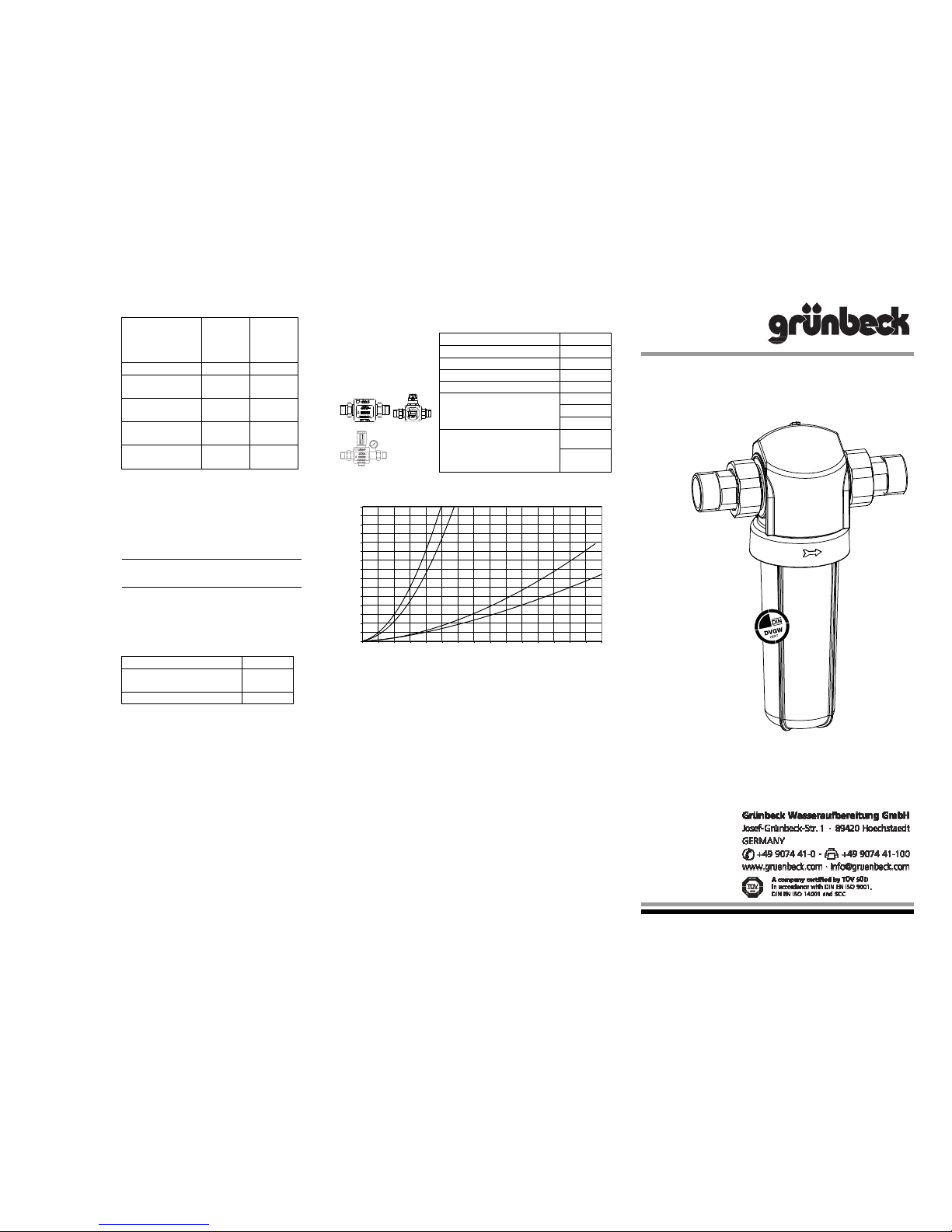
Pressure loss curve
0,0
0,1
0,2
0,3
0,4
0,5
0,6
0,7
0,8
0,9
1,0
1,1
1,2
1,3
1,4
1,5
0,0 2,0 4,0 6,0 8,0 10,0 12,0 14,0 16,0 18,0 20,0 22,0 24,0 26,0 28,0 30,0
Durchfluss [m³/h]
Differenzdruck [bar]
FS-B DN 32FS-B DN 25
FS-B DN 40
FS-B DN 50
Operation Manual
Fine filter FS-B
Edition 05/2013
Order no. 076 101 196-inter
Differential pressure [bar]
Flow [m³/h]
Page 2
General notes
Our systems have to be installed by an
approved sanitary or heating company.
Prior to installation, check the components for shipping damage.
The devices must be protected against
frost and must not be installed near heat
sources which radiate a lot of heat.
Attention: Do not clean the filter with
cleaning agents that contain alcohol or
solvents!
In case of drinking water that contains a
lot of coarse dirt, a coarse filter must be
installed upstream.
1 Application
The FS-B filters are designed for the
filtration of drinking water. The filters are
not suited for circulation water that has
been treated with chemicals. Furthermore, it is neither suited for oils, greases, solvents, soaps and other lubricating
media nor for the separation of watersoluble materials. The filters may be
used in the pressure and negative pressure range.
2 Technical specifications
Fine filter FS-B
Connection diameter 1“ 1¼“ 1½“ 2“
Nominal connection diameter [DN] 25 32 40 50
Nominal flow at
p 0.2(0.5) bar
[m³/h] 3.7(6,0) 4.0(6,2) 11.1(19,9) 13.9(23,3)
Filter fineness [µm] 80
Diameter of upper/ lower
outlet
[µm] 140/80
Nominal pressure PN 16
Total height [mm] 265 508
Replacement height for
filter element
[mm] 150 390
Length with/without screw
connections
[mm] 182/100 191/100 283/160 277/160
Empty weight [kg] 1.2 1.4 3.7 4.4
DVGW registration mark
NW-9301BT0200
Max. water / ambient
temperature
[°C] 30/40
Order no.
101 170 101 175 101 180 101 185
3 Installation
requirements
Please observe local installation guidelines
and general regulations as well as technical specifications.
The installation site must be frost-proof
and must ensure the protection of the
filter against chemicals, dyes, solvents,
vapours and direct sunlight.
Observe flow direction ( indicated on
the housing)! Install voltage-free. The
installation site must be frost-proof.
The filter should be installed in equally
dimensioned pipes according to its
nominal diameter.
4 Scope of
delivery
Filter with protective cover and built-
in maintenance indicator.
Screw connections with seals made
of LD-PE.
Filter element 80 µm
Operation manual
5 Installation
As per DIN EN 806-2 and DIN 1988-200
the FS-B filter has to be installed in the
cold water pipe downstream of the water
meter and upstream of the distribution
pipes respectively upstream of the devices to be protected. Install shut-off
valves upstream and downstream of the
filter (refer to fig. 1). The filter is suited
for horizontal installation only.
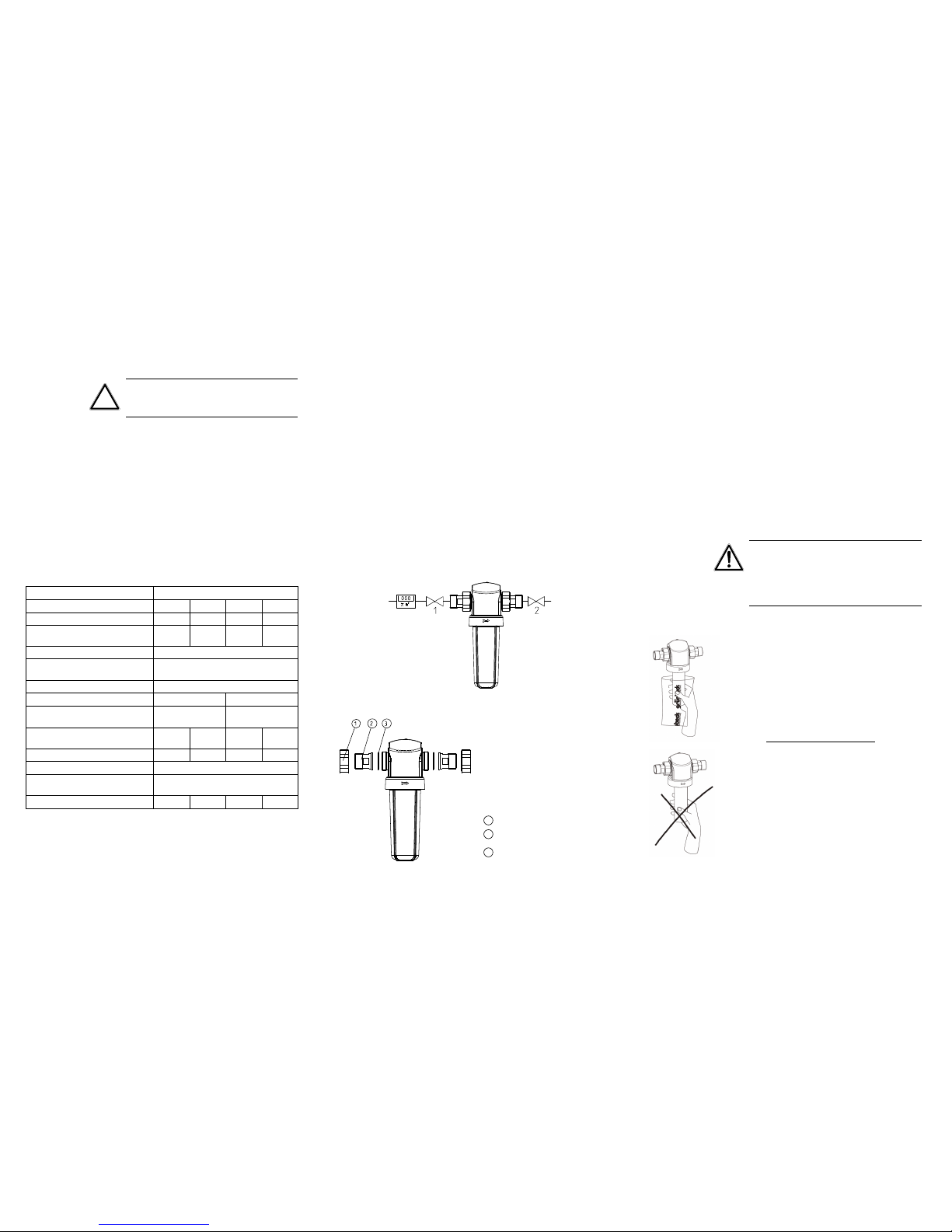
Fig. 1: Installation drawing FS-B front view
1
Union nut
2
Insert
3
Flat seal
Fig. 2: View FS-B
6 Start-up
After completion of the installation, put
the filter into operation by opening the
shut-off valves. Then de-aerate the
piping via the nearest screw connection.
Leakage test
A leakage test must be performed on the
filter directly after installation and after
each time maintenance work was performed. In order to check the filter for
tightness, the highest pressure admissible must be applied.
7 Inspection /
Maintenance
According to the DIN Standard EN 8065, the operator must inspect the filters
every two months (functional inspection).
During the inspection, the filter element
must be checked for contamination and
be replaced, if necessary (contamination
and/or increased differential pressure).
Check for tightness.
Furthermore, maintenance has to be
performed by the operator or the installation company every six months.
Warning! According to DIN EN 806-5
the filter element must be replaced for
hygienic reasons every 6 months. Furthermore, we recommend replacing the
seal of the protective cylinder every 2
years using a set of seals.
Replacement of
filter element
Fig.3: Replacement of
filter element
How to proceed
Place a bucket beneath the filter.
Close the shut-off valves.
Depressurize the pipe.
Manually unscrew the filter cylinder.
Remove the dirty filter element from
the supporting fabric and replace by
new filter element. For hygienic reasons, do not touch the new filter element with bare hands.
Hygienic filter replacement:
Open the foil and push the filter element including the foil over the supporting fabric, pull off the foil without touching the filter element. (see fig. 3)
Check that the sealing surfaces as
well as the O-ring are clean and
manually screw on the filter cylinder
to the stop.
Start up as described in point 6.
Edited by: KONS-fger-mrie G:\BA-101196-INTER_FS-B.DOC
 Loading...