

Page 1
We understand water.
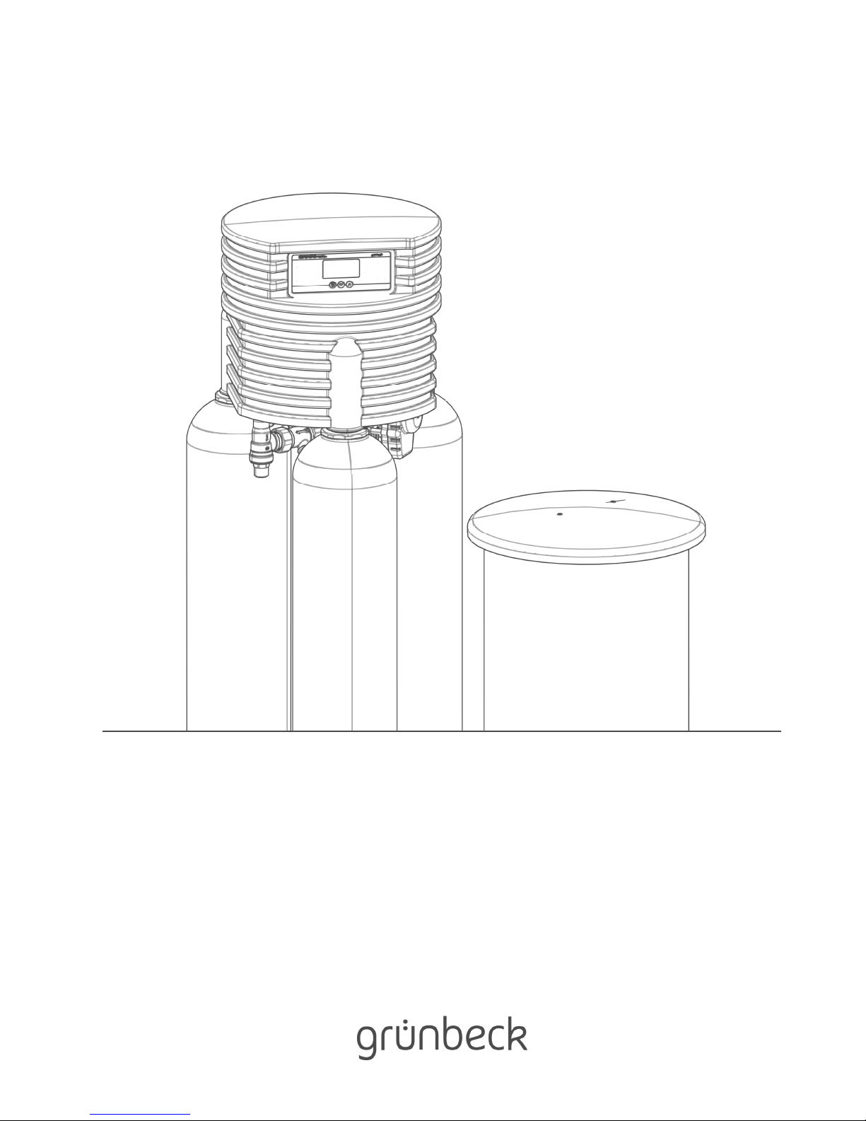
Softening | Water softener Delta-p
Operation manual
Page 2

Central Contact
Germany
Sales
Phone +49 9074 41-0
Technical Service
Phone +49 9074 41-333
Fax +49 9074 41-120
Availability
Monday to Thursday
7:00 am - 6:00 pm
Friday
7:00 am - 4:00 pm
Your local point of contact: see
accompanying list of
representatives
Copyright
The manufacturer reserves the copyright to this operation manual. Without the written consent of
Grünbeck Wasseraufbereitung GmbH, no part of this manual may be reproduced in any way, nor
may any part be processed, duplicated or distributed using electronic systems.
Contraventions of the aforementioned requirements shall be subject to compensation in damages.
We reserve the right to modifications.
© by Grünbeck Wasseraufbereitung GmbH
Translation of the original operation manual
Edition of the operation manual: December 2017
Order no.: TD3-BM001en_014
Page 3

Table of contents
3 | 74
Table of contents
1
About this manual ............................................... 4
1.1Other applicable documents ................................ 4
1.2Target group ........................................................ 4
1.3Storage of the documents .................................... 4
1.4Symbols used ...................................................... 4
1.5Typographical conventions .................................. 5
1.6Validity of the manual .......................................... 7
1.7Type designation plate ......................................... 7
2Safety ................................................................... 8
2.1Safety measures .................................................. 8
2.2Safety information ................................................ 8
2.3Regulations .......................................................... 9
2.4Obligations on the specialist installer and/or
specialist company .............................................. 9
2.5Responsibilities of the owner-user ..................... 10
2.6Safety information for the specific system ......... 10
2.7Packaging, transport, storage and installation ... 11
3Product description .......................................... 12
3.1Intended use ...................................................... 12
3.2Foreseeable misuse .......................................... 12
3.3Product components .......................................... 13
3.4Accessories ....................................................... 13
3.5Functional description ........................................ 15
4Control unit ........................................................ 16
4.1Overview ............................................................ 16
4.2Display screens ................................................. 16
4.3Navigating the control unit ................................. 18
4.4Menu structure ................................................... 20
4.5Programming levels ........................................... 21
5Installation ......................................................... 25
5.1Requirements with regard to the installation site 25
5.2Checking the scope of supply ............................ 26
5.3Installing the product .......................................... 27
5.4Preparation ........................................................ 28
6Start-up .............................................................. 30
6.1Preparations ...................................................... 30
6.2Adjusting the water softener Delta-p .................. 33
6.3Handing over the operation manual to the
operator ............................................................. 33
7Operation ............................................................34
7.1Information about the basic display ....................34
7.2Request information ...........................................34
7.3Trigger regeneration manually ............................35
7.4Set current time ..................................................35
7.5Setting the water hardness .................................36
7.6Setting the operating parameters .......................37
7.7Refilling salt tablets .............................................37
8Cleaning, inspection, maintenance ..................38
8.1Intervals ..............................................................38
8.2Cleaning .............................................................38
8.3Inspection ...........................................................39
8.4Maintenance .......................................................39
8.5Consumables ......................................................41
8.6Wearing parts .....................................................42
9Fault ....................................................................43
9.1Messages on the display ....................................43
9.2Other observations .............................................47
10Disposal ..............................................................48
11Technical specifications ...................................49
11.1Continuous flow curve ........................................52
11.2Pressure loss curves ..........................................53
12Other information ...............................................54
12.1Explanation of terminology .................................54
12.2Soft water with blending .....................................54
12.3Sodium content in the water ...............................55
12.4Hardness range ..................................................55
13Mounting instructions .......................................56
13.1Water installation ................................................56
13.2Electrical installation ...........................................61
13.3Overview of electrical cable connection .............63
14Operation log ......................................................65
EC-Declaration of Conformity ....................................70
Index .............................................................................71
Page 4
About this manual
4 | 74
BA_TD3-BM001en_014_Delta-p.docx
1 About this manual
1.1 Other applicable documents
For Delta-p, the following documents are regarded as applicable documents:
● For Grünbeck's technical customer service-/authorised service company:
Operation manual for Grünbeck's technical service
Order no.: 185 951
● The manuals of all accessories used shall apply.
1.2 Target group
This manual is intended for specialist installers and owners/users.
1.3 Storage of the documents
This manual and all other applicable documents must be kept so as to be available if
required. Make sure that your specialist installer enters the proper start-up and annual
maintenance in chapter 14 of the operation log.
1.4 Symbols used
This symbol identifies information and instructions that you must comply with for your
personal safety as well as to avoid damage to property.
This symbol identifies instructions that you must comply with in order to avoid damage to
property.
This symbol identifies important information about the product or its handling.
This symbol identifies work that is only allowed to be carried out by a specialist installer. In
Germany, the installation company must be registered in an installation directory of a water
supply company acc. to §12(2) AVB Wasser V (German Ordinance on General Conditions
for the Supply of Water).
This symbol designates tasks that may only be performed by Grünbeck's technical
customer service-/authorised service company or by specialist installers trained by
Grünbeck.
This symbol identifies work that may only be carried out by electronically trained personnel
according to the VDE guidelines or according to the guidelines of similar local institutions.
Page 5

About this manual
5 | 74
BA_TD3-BM001en_014_Delta-p.docx
1.5 Typographical conventions
The following typographical conventions are used in this manual:
1.5.1 Menu paths
Menu paths are shown in a different font. The sequence of the menus is indicated by the ">"
sign.
Status level>Menu level>Submenu
1.5.2 Menu items
Menu items, e.g. within a software menu, are highlighted in grey.
Menu item
1.5.3 Buttons
Buttons are depicted with a doted frame.
Button
1.5.4 Instructions
Single-step instructions or instructions where the sequence of the actions is unimportant are
indicated as follows:
► Action
Multi-step instructions where the sequence of the actions must be observed are indicated as
follows:
1. First step
a First action in the first step
b Second step of the first action
2. Second action
Results of an instruction are indicated as follows:
» Result
Page 6
About this manual
6 | 74
BA_TD3-BM001en_014_Delta-p.docx
1.5.5 Lists
Bullet symbols used:
● First list point (level 1)
• First bullet point (level 2)
• Second bullet point (level 2)
● Second list point (level 1)
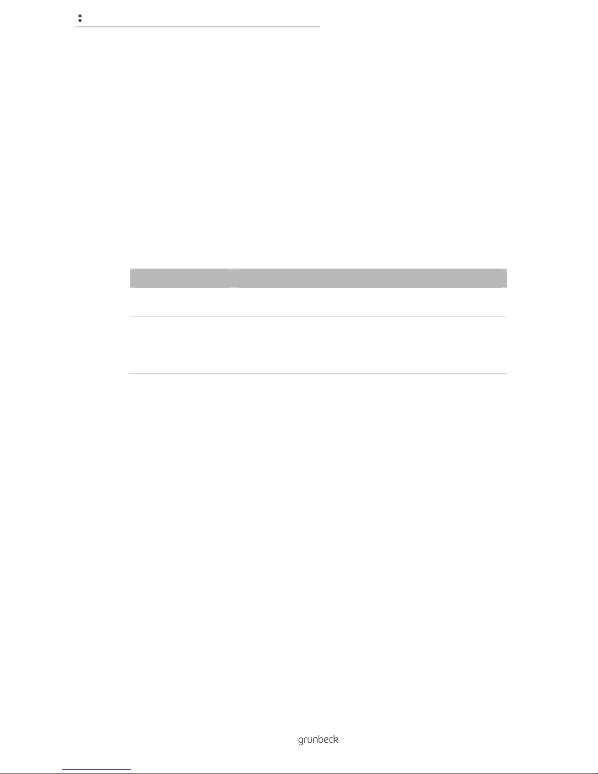
1.5.6 Operating states
Tanks described in the text, referred to below as exchangers, assume different operating
states. The following convention applies to the exchangers:
Depiction Explanation
Exchanger* Is in operation and usually has the lower remaining capacity. Is
due for regeneration next.
Exchanger** Is in operation and usually has the higher remaining capacity. Is
due for regeneration next but one.
Exchanger*** Is exhausted and is currently being regenerated or has already
been completely regenerated.
Page 7
About this manual
7 | 74
BA_TD3-BM001en_014_Delta-p.docx
1.6 Validity of the manual
This manual applies to the following products:
● Water softener Delta-p
● Water softener Delta-p-I
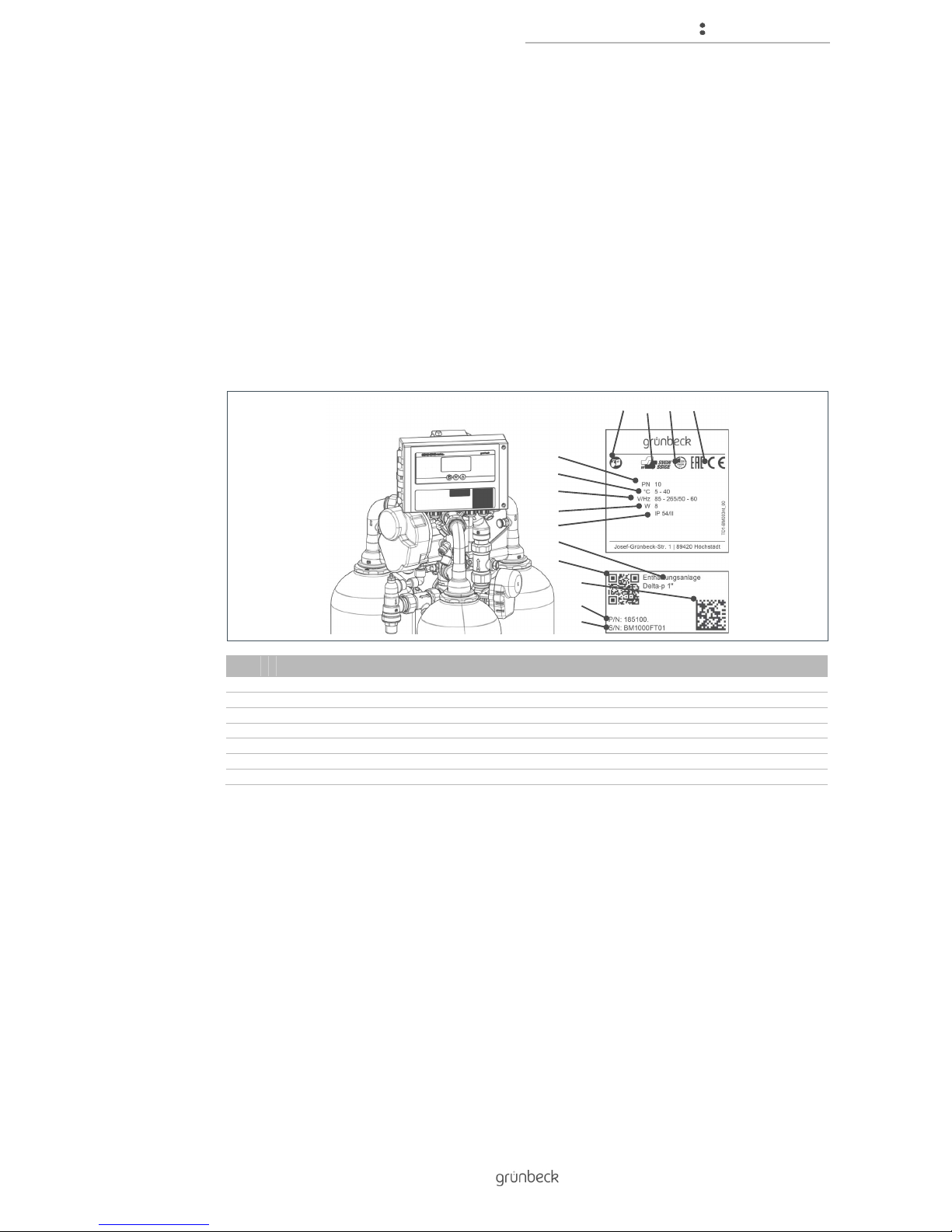
1.7 Type designation plate
The type designation plate can be found under the dome on the control unit of the water
softener below the display.
No. Designation No. Designation
1 Observe the operation manual 8 Power input
2 SVGW test mark 9 Index of protection
3 DVGW test mark 10 Product designation
4 CE mark 11 QR code
5 Nominal pressure 12 Data matrix code
6 Ambient temperature 13 Order no.
7 Power supply 14 Serial number
Please specify the data shown on the type designation plate in order to speed up the
processing of your enquiries or orders.
Therefore enter the necessary information in the table below to have it readily available
whenever necessary.
Product designation: ____________________
Order no.: ____________________
Serial no.: ____________________
2 1 3
4
5
9
6
8
7
12
10
11
14
13
Page 8
Safety
8 | 74
BA_TD3-BM001en_014_Delta-p.docx
2 Safety
WARNING: Contamination of drinking water due to improper handling.
● Risk of infectious diseases.
► Have the installation, start-up and annual maintenance carried out by specialist
installers only.
2.1 Safety measures
● Carefully read this manual before operating your product.
● Install the product in a frost-free room. Otherwise, the system may suffer
irreparable damage. The consequence can be a water damage.
● Only use genuine spare parts for maintenance or repair. If unsuitable spare parts
are used, the warranty for your product will be void.
● Do not use products which have a damaged power supply cable. This can lead to
injuries due to electric shock. Have damaged power supply cables replaced without
delay.
● Comply with the hygiene instructions in chapter 8. Failure to comply can result in
microbiological contamination of your drinking water installation.
● Only have persons working on your system that have read and understood the
present manual and that are qualified to do such work due to their vocational
training.
● Only operate the product if all components are installed properly.
● Safety device must never be removed, bridged or otherwise tampered with.
2.2 Safety information
This manual contains instructions that you must comply with for your personal safety as well
as to avoid damage to property. The information and instructions are highlighted by a
warning triangle and have the following structure:
CAUTION: Type and source of danger.
● Possible consequences
► Preventive measures
Page 9

Safety
9 | 74
BA_TD3-BM001en_014_Delta-p.docx
The following signal words were defined subject to the degree of danger and may be used in
the present document:
● DANGER means that serious or fatal injuries will occur if the corresponding
precautionary measures are not taken.
● WARNING means that serious or fatal injuries may occur if the corresponding
precautionary measures are not taken.
● CAUTION means that minor injuries may occur if the corresponding precautionary
measures are not taken.
● NOTE (without a warning triangle) means that damage to property can occur if the
corresponding safety measures are not taken.
2.3 Regulations
Comply with the following regulations and directives, amongst others, during installation and
start-up:
● Statutory regulations on environmental protection
● Provisions of the employers' liability insurance associations
● DIN EN 806 Specifications for installations inside buildings conveying water for
human consumption
● VDI/DVGW 6023 part 6
● Low Voltage Directive 2014/35/EU, Appendix IV
2.4 Obligations on the specialist installer and/or specialist
company
Comply with the following specifications to ensure correct and safe function of the product:
● Only perform activities described in this manual.
● Perform all activities in accordance with all applicable standards and regulations.
● Brief the owner/user on the function and operation of the product.
● Advise the owner/user of the maintenance of the product.
● Instruct the owner-user about possible dangers that can arise during operation of
the product.
Page 10

Safety
10 | 74
BA_TD3-BM001en_014_Delta-p.docx
2.5 Responsibilities of the owner-user
Comply with the following specifications to ensure correct and safe function of the product:
● Arrange for only a specialist installer to carry out installation, start-up and
maintenance.
● Have the product explained to you by the specialist installer.
● Only perform activities described in this manual.
● Do not carry out any activities that are explicitly indicated for a specialist installer.
● Only use this product in accordance with its designated application.
● Make sure that the required inspection- and maintenance work is carried out.
● Keep this manual.
2.6 Safety information for the specific system
WARNING: Risk of contamination of the drinking water in case of incorrect discharge of the
regeneration water
● Health risk due to contamination of the drinking water.
► When installing a discharge line for the regeneration water, do not connect any
devices directly to the drain outlet of the water softener. To install a drain, use
only the supplied black hose to allow the regeneration water to flow to the drain
connection.
WARNING: Danger of contamination of the drinking water due to prolonged periods of
inactivity of the system without automatic regeneration.
● Bacterial growth in the drinking water.
► Automatic regeneration with disinfection counteracts the bacterial growth. Do not
disconnect the water softener from the power and water supply when you are
absent for longer periods of time.
WARNING: Danger of drinking water contamination due to stagnation.
● Bacterial growth in the drinking water.
► According to VDI/DVGW 6023, filling the system with raw water prior to starting
the designated operation is prohibited.
Page 11
Safety
11 | 74
BA_TD3-BM001en_014_Delta-p.docx
CAUTION: Insoluble impurities in the salt may cause malfunctions at the brine valve and at
the injector of the control valve.
● Dosage of salt according to requirements is not guaranteed.
► A defined salt quality is required for the reliable function of the water softener.
Only use salt tablets as per DIN EN 973 type A.
CAUTION: Blocking of reverse osmosis systems by blended raw water.
● The functionality of reverse osmosis systems is threatened.
► If the water softener is installed before a reverse osmosis system, the feed line to
the reverse osmosis system is not allowed to be configured as soft water with
blending.
CAUTION: Risk of uncontrolled water leakage during regeneration if there is a power
failure.
● Uncontrolled water leakage into the drain or brine tank.
► If there is a power failure, check the water softener and block the raw water
supply if necessary.
2.7 Packaging, transport, storage and installation
Transport and store the product:
● in its original packaging
● correct way up
Transport, store and install the product free from:
● Strong heat
● Frost
● Direct sunlight
● Chemicals, dyes, solvents and their vapours
Page 12
Product description
12 | 74
BA_TD3-BM001en_014_Delta-p.docx
3 Product description
3.1 Intended use
The water softeners Delta-p are have been developed for the continuous production of
softened and partially softened water and can be used in these areas:
● Continuous soft water supply
● Softening and partial softening of:
• Well water
• Process water
• Boiler feed water
• Cooling water
• Air-conditioning water
• Cold drinking water
• industrial water
3.2 Foreseeable misuse
The water softeners Delta-p cannot be used in these areas:
● Slow removal of water
● Widely diverging performance
● Load above nominal flow
Also comply with the information in the technical specifications (refer to chapter 11)
Page 13
Product description
13 | 74
BA_TD3-BM001en_014_Delta-p.docx
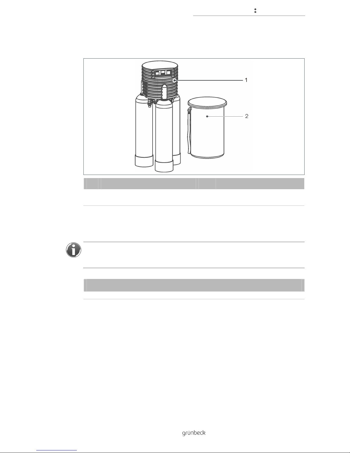
3.3 Product components
No. Designation No. Designation
1 Water softener with central control
valve and control unit
2 Brine tank with sieve bottom
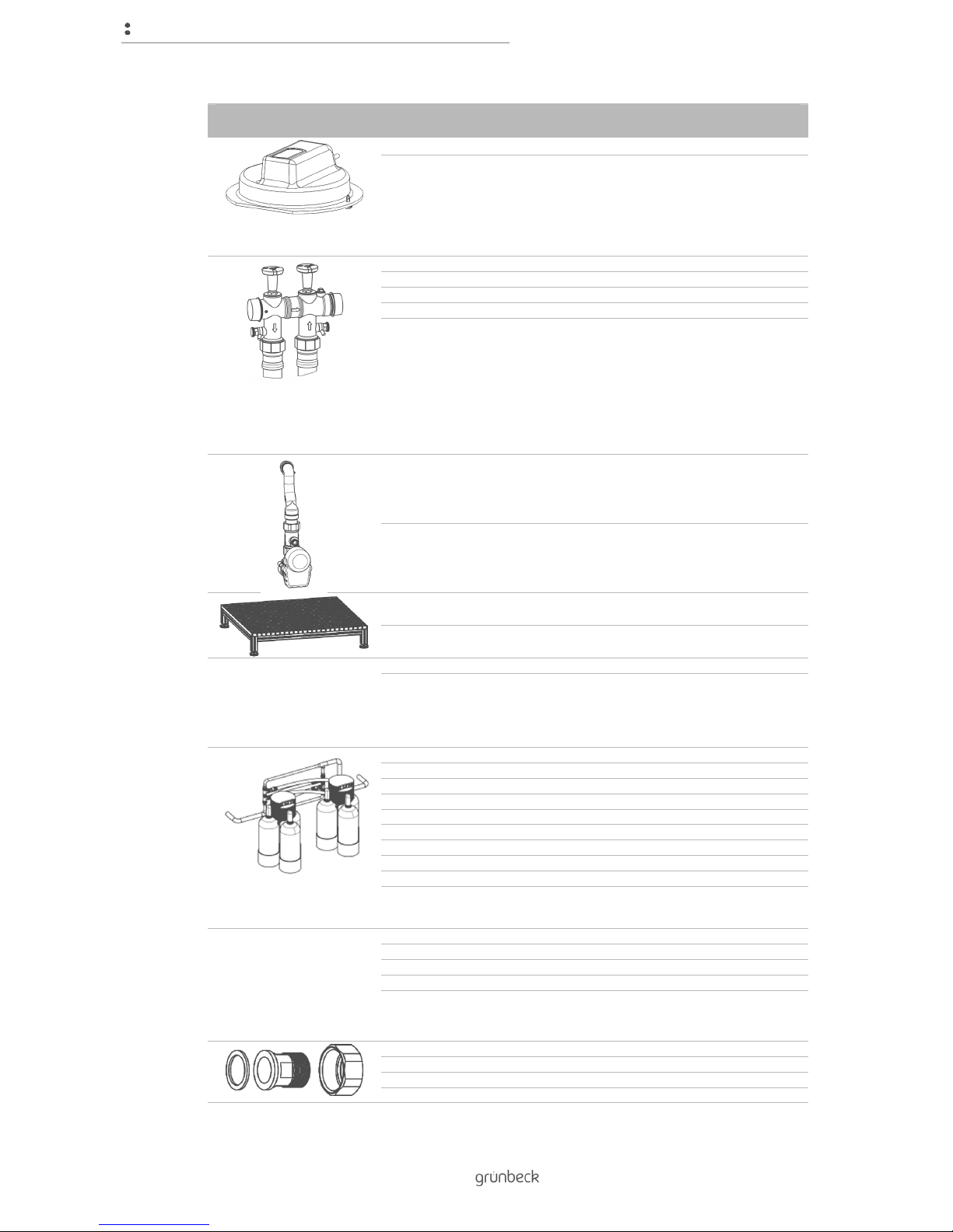
3.4 Accessories
You can retrofit your product with additional accessories. Please contact your local
Grünbeck representative or Grünbeck’s headquarters in Hoechstaedt for details (refer to
www.gruenbeck.de).
Water softener Delta-p
Accessories
Image Designation Order-no.
Page 14
Product description
14 | 74
BA_TD3-BM001en_014_Delta-p.docx
Water softener Delta-p
Accessories
Pre-alarm salt supply 185 335
Infrared light sensor to detect the minimum quantity of
salt in the brine tank. Signal via control unit.
Connection set 1"-1¼" 185 807
Connection set 1"-1¼"-I 185 808
Connection set 1½"-2" 185 823
Connection set 1½"-2"-I 185 824
Connection set (for convenient connection to the water
installation) compact valve block, built-in overflow valve
(not with Delta-p-I version), shut-off valves for hard and
soft water, sample valves for raw and soft water (only
with 1"-1¼"), 2 flexible, pressure-resistant connection
hoses. (For Switzerland, connection hoses are not
included in the scope of delivery. Install the fixed
pipework on site.)
Blending with Delta-p 1"-1¼" 185023
Blending with Delta-p 1½"-2" 185006
Pedestal Delta-p 1"-1¼" 770x770x200 mm 185 820
Pedestal Delta-p 1½"-2" 880x880x200 mm 185 825
M-Bus-measuring transducer D-DAM complete 115 850
Transmitting the flow and meter readings, as well as
statistical values of the turbine water meter via M-Bus
(IEC870). The pulse output is proportional to the flow
rate at the analogue output and relay contact of the
Grünbeck-control.
Dimensions: 160x240x160 mm.
Parallel piping Delta-p 2x1" PVC 185 450
Parallel piping Delta-p 2x1¼" PVC 185 455
Parallel piping Delta-p 2x1½" PVC 185 460
Parallel piping Delta-p 2x2" PVC 185 465
Parallel piping Delta-p 3x2" PVC 185 470
Parallel piping Delta-p 2x1" VA 185 400
Parallel piping Delta-p 2x1¼" VA 185 405
Parallel piping Delta-p 2x1½" VA 185 410
Parallel piping Delta-p 2x2" VA 185 415
Parallel piping (Tichelmann-piping) of two or several
triple water softeners, including all the necessary
connection pieces and connection sets.
Cascade connection Delta-p 1"-1¼" - 2-way 185 360
Cascade connection Delta-p 1½"-2" - 2-way 185 365
Cascade connection Delta-p 2" - 3-way 185 370
Cascade connection Delta-p 2" - 4-way 185 375
Cascade control for parallel-piped water softeners
Delta-p. The cascade connection is required in
conjunction with water softeners Delta-p in parallel
connection.
Screw connection for connection block 1" 185 846
Screw connections for connection block 1¼" 185 847
Screw connections for connection block 1½" 185 848
Screw connection for connection block 2" 185 849
Page 15
Product description
15 | 74
BA_TD3-BM001en_014_Delta-p.docx
Water softener Delta-p
Accessories
Screw connections for connection block. Water meter
screw connections with seals for pre-installation of the
connection block.
Disinfection set Delta-p 1"-1¼" 185 830
Disinfection set Delta-p 1 ½"-2" 185 835
Disinfection of the water softener, e.g. after extremely
long periods of stagnation or contamination. With
GENO-perox, canister and personal protective
equipment.
Communication module DE200 Profibus 185 890
Profibus-DP slave module, including GSD-file
Brine tank 210 litres 185 510
Brine tank 750 litres 185 525
3.5 Functional description
3.5.1 Physical
The water softeners Delta-p are equipped with a central control valve for the three
exchangers and are controlled depending on the quantity.
Regeneration is triggered when the next exchanger to be regenerated is exhausted or 50%
of the next but one exchanger to be regenerated is exhausted.
The water softener regenerates with raw water.
3.5.2 Chemical
The exchanger contains ion exchanger resin in the form of small resin beads. Sodium ions
adhere to each resin bead. Hard water with a large proportion of calcium and magnesium
ions flows through the exchanger.
The ion exchanger resin absorbs calcium and magnesium ions from the water in exchange
for sodium ions. This reaction is called ion exchange. The calcium and magnesium ions are
retained in the exchanger. Soft water without calcium and magnesium ions, but containing
sodium ions, leaves the exchanger.
This process continues until no more sodium ions are available. The ion exchanger resin is
exhausted.
The exchange can be reversed if a large amount of sodium ions is added.
The exchanger is rinsed with brine, water containing salt.
By their sheer number, sodium ions displace calcium and magnesium ions on the ion
exchanger resin. This water containing calcium and magnesium ions is discharged to the
drain. The initial condition is restored.
Page 16
Control unit
16 | 74
BA_TD3-BM001en_014_Delta-p.docx
4 Control unit
4.1 Overview
No. Designation No. Designation
1 Display 3
Button
2 Explanations 4
Button
5
Button P
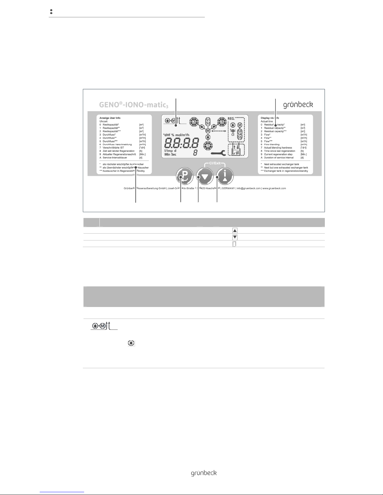
4.2 Display screens
Display GENO-IONO-matic
3
First line
Figure Explanation
Blending valve
not with Delta-p-I
flashes while water is withdrawn (ratio of raw water).
Blending motor runs (M) in order to maintain a constant blending hardness
in case of a variable withdrawal volume.
1
2
2
5 4 3
Page 17
Control unit
17 | 74
BA_TD3-BM001en_014_Delta-p.docx
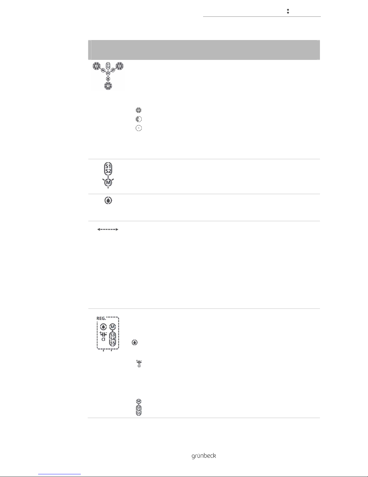
Display GENO-IONO-matic
3
First line
Exchanger tank
At the status level:
The two exchangers in operation are displayed with their number and
remaining capacity.
The eight circle segments each represent 12.5 % remaining capacity.
Residual capacity between 87.5 % and 75 %.
Residual capacity between 50 % and 37.5 %.
Exchanger exhausted.
In the Information menu level:
Remaining capacity and flow rate displayed in the numeric display refer to
the exchanger which has its number displayed.
Transfer valve
Motor transfer valve is running (M) for switching to the next pair of
exchanger tanks; microswitches (S1, S2) are actuated to detect when this
position has been reached.
Drop symbol
Flashes when there is flow at the corresponding turbine water meter 1, 2
or 3.
Flow arrow
Indicates the direction of flow when there is flow between the regeneration
and transfer valves.
First filtrate: Transfer valve -> Regeneration valve; waste water to the
drain.
Salting/slow rinsing: Regeneration valve -> Transfer valve, brine or
water to the exchanger.
Backwashing: Regeneration valve -> Transfer valve, waste water to the
drain.
Filling the brine tank: No water is flowing through this connection,
direction arrow not active.
Regeneration valve
Display during the entire regeneration.
Regeneration step fill brine tank:
Drop symbol flashes when there is flow at the turbine water meter.
Regeneration step - salting:
Symbol appears if the electrolysis-current for chlorine production
(disinfection of the exchanger) is OK.
Motor regeneration valve is running (M) for switching to the next
regeneration step; microswitches (S3, S4, S5) are actuated to detect
when the next regeneration step has been reached
Symbols show the current status
Page 18
Control unit
18 | 74
BA_TD3-BM001en_014_Delta-p.docx
Display GENO-IONO-matic
3
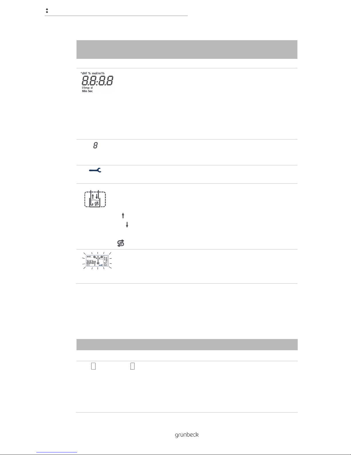
Second line
Figure Explanation
Numbers and unit display
At the status level:
Indicates the time.
In the Information menu level and the Operator menu level:
Indicates the numerical value of the parameter in the menu; if available
with physical unit.
In the case of malfunctions / warnings:
The currently fault or warning Er x is displayed.
Index/parameters
Displays the consecutive number of the current value in the numerical
display 9 for guidance.
Screw wrench
Displayed when maintenance interval has expired.
Brine tank
Displayed during regeneration.
Appropriate arrow for the corresponding regeneration step appears:
Brine is drawn out of the tank
Raw water is fed into brine tank
Pre-alarm salt supply, if installed:
Symbol appears when salt needs to be refilled.
Backlight
Is switched on up to 10 minutes after the last button press.
Each press of a button initially activates the back lighting.
Flashes during malfunctions/warnings.
4.3 Navigating the control unit
4.3.1 Buttons of the control unit
Control unit GENO-IONO-matic3
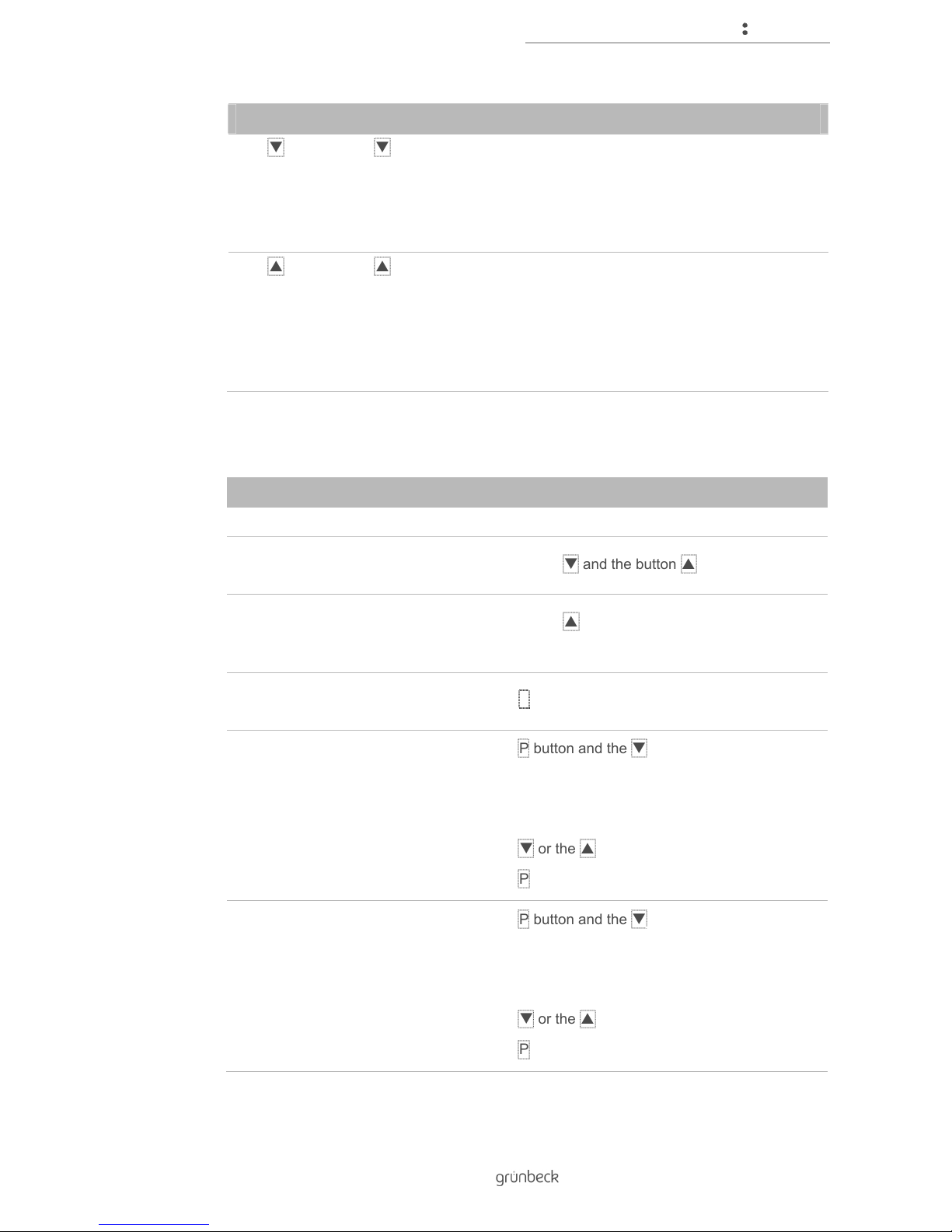
Figure Designation Function
P Button P
In the status level:
Switches to User menu level. (> 5 s press)
Acknowledges malfunctions.
In the Menu level User:
Opens parameters.
Stores the settings and closes parameters.
Page 19
Control unit
19 | 74
BA_TD3-BM001en_014_Delta-p.docx
Control unit GENO-IONO-matic3
Button
In the status level:
Triggers regeneration by hand. (> 5 s press)
In the Menu level User:
Returns to the previous parameter.
Decreases numerical values.
Button
In the status level:
Calls up the Information menu level.
Advances the display.
In the Menu level User:
Switches to the next parameter.
Increases the numerical values.
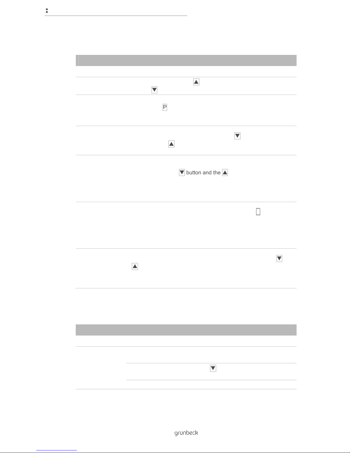
4.3.2 Select menu level
Control unit GENO-IONO-matic3
Objective Step
Status level
► Press the button and the button at the same time.
Information menu
level
► Press the button in the status level. 1x - 11x, rotating
through the display back to the basic display.
Menu level User
► Press the P button in the status level for more than 5°s
Menu level
Programming
1. Press the P button and the button in the status level
at the same time for more than 1 s.
» The display switches from time to the three flashing
digits "000", preceded by a "C".
2. Press the or the button to select code 290.
3. Press the P button to confirm your selection.
Advanced
programming menu
level
1. Press the P button and the button in the status level
at the same time for more than 1 s.
» The display switches from time to the three flashing
digits "000", preceded by a "C".
2. Press the or the button to select code 113.
3. Press the P button to confirm your selection.
Page 20
Control unit
20 | 74
BA_TD3-BM001en_014_Delta-p.docx
4.3.3 Setting the parameters
Control unit GENO-IONO-matic3
Objective Step
Select parameters
On every menu level, the button switches to the next parameter
and the button switches to the previous parameter.
Open parameters When the intended parameter is displayed on the screen, open it by
pressing the P button.
» The value of the parameter flashes.
Change parameter
If the opened parameter flashes, press the button for lower
values and the button for higher values.
Close parameter
without saving
If you want to exist the settings for the opened parameter without
changes, press the button and the button at the same time.
» The parameter will be closed and the display shows the
unchanged value continuously.
Save parameters
If the correct value flashes on the display, press the P button to
save it.
» The parameter will be closed and the display shows the
set value continuously.
Exit menu level
When you have made and saved the desired settings, press and
buttons simultaneously.
» The display shows the basic display on the status level.
4.4 Menu structure
Control unit GENO-IONO-matic3
Menu level Menu items Values/settings
Status level Acknowledge
malfunctions
Press one of the buttons
Regeneration by
hand
Press the button for more than 5°s
Select menu level (refer to chapter 4.3)
Page 21
Control unit
21 | 74
BA_TD3-BM001en_014_Delta-p.docx
Control unit GENO-IONO-matic3
Information 0 Remaining capacity exchanger *
1 Remaining capacity exchanger **
2 Remaining capacity exchanger ***
3 Flow rate exchanger *
4 Flow rate exchanger **
5 Flow rate exchanger ***
6 Flow rate blending
7 Soft water hardness actual value
8 Time since last regeneration
9 Current regeneration step
A Current regeneration step
Step 1-3:
Regeneration step: Remaining time of the
current regeneration step
Step 4:
Regeneration step: Flow rate
Operator Set the time Hours and minutes separately, [hh:mm]
Set the actual raw
water hardness
Adjust soft water
hardness with
blending
Must not be changed with Delta-p-I
Programming
levels
To the settings and displays
(refer to chapter 4.5).
4.5 Programming levels
NOTE: Non-compliance will result in serious damage to product and user.
● The function of the product can be significantly impaired and result in a health
hazard for users.
► The settings described here may only be performed by specialist installers and
trained personnel.
Page 22
Control unit
22 | 74
BA_TD3-BM001en_014_Delta-p.docx
The GENO-IONO-matic3 controls the operating and regeneration processes of water
softeners in the Delta-p series automatically depending on the selected operating mode,
water consumption, daily interval and time selected. The different parameters of the water
softener are stored in the programming levels and can be set with code protection via the
menu navigation.
A programmable input, a programmable output and an input for the pre-alarm salt supply
accessory are available
4.5.1 Menu level Programming
Status level>Programming menu level
Parameters of the Programming menu level
Control unit GENO-IONO-matic3
Index/parameters Meaning Factory
settings
Setting range
0 Hardness unit Configuration of the display for
hardness values with corresponding
unit. Applies to raw water and soft
water hardness as well as the
capacity value
0 0 = °dH
1 = °f
2 = mol/m³
1 Water softener-
Data record
CA31: Delta-p 1"
CA32: Delta-p 1¼"
CA35: Delta-p 1½"
CA36: Delta-p 2"
Warning: Changes only permitted by
Grünbeck's technical
service'-/authorised service
company!
Depending
on water
softener
(nominal
width)
2 Capacity rate CA31: 48
CA32: 79
CA35: 165
CA36: 229
Depending
on water
softener
(nominal
width)
Indication only
3 Turbine water meter-
Constant exchangers
0.0314 Indication only
4 Turbine water meter
constant regeneration
valve
CA31: 0.0313
CA32: 0.0313
CA35: 0.0325
CA36: 0.0325
Depending
on water
softener
(nominal
width)
Indication only
5 Turbine water meter
constant blending valve
0.0309 Indication only
6 Activation time Applies to regeneration over a daily
interval
00: 00: ... 23:
7 Activation time Applies to regeneration over a daily
interval
:00 :00 ... :59
8 Disinfection program Is started by reprogramming to
value 1. Attention: Observe the
instructions of the
disinfection-chemical!
0 0 ... 1
9 Triple manual
regeneration
Is started by reprogramming to
value 1/2/3. All 3 exchangers are
regenerated 1x in succession up to
3x. In between there is a waiting time
of 15 minutes in each case.
0 0 ... 3
Page 23
Control unit
23 | 74
BA_TD3-BM001en_014_Delta-p.docx
4.5.2 Advanced programming menu level
Status level>Advanced programming menu level
Parameters of the Advanced programming menu level
Control unit GENO-IONO-matic3
Index/parameters Meaning Factory
setting
Setting range
0 Programmable input
function
0 = No function
1 = External release of regeneration
2 = External lock of regeneration
3 = External 3-way regeneration
triggering
4 = Reserved function
0 0 ... 2
1 Programmable output
function
0 = No function
1 = Closed during regeneration step
1 Salting
2 = Closed during the entire
regeneration
3 = Closed if flow rate with flow at
exchanger * and
exchanger ** = 0 m³/h or with
bottle changeover or in case of
malfunction
80/210 = reserved function
0 0 ... 3/80/210
2 Delay time for
programmable output
with setting = 3
After the bottle changeover has been
completed, the contact opens again
with a delay.
0.5 0.1 … 9.9
3 Activation pre-alarm
salt supply (optional)
0 = is not evaluated
L = Infrared-light sensor detects the
filling level in the brine tank. If no
object is detected within the
adjustable switching gap for
longer than 5 min, warning Er A +
symbol appears
0 0 ... 999/L
reserved function 0 1 … 999
4 Serial interface RS 485 0 = deactivated
1 = Optional module
DE2000 Profibus available
2 = Protocol mode RTU for
networking with reverse osmosis
GENO-OSMO-X
0 0 … 2
5 Pulse divider for
EXAcount pulse
output 1: …
The input pulses of the water meters
exchanger */exchanger **/blending
are used for the pulse output.
1 (0)/1/12/18/31/42
Note: Divider "0" must not be used in
combination with the dosing
computer EXADOS!
Setting "0" is reserved for the
Delta-p- cascade circuit.
Observe the following tables.
Page 24

Control unit
24 | 74
BA_TD3-BM001en_014_Delta-p.docx
Divider for index/parameter 5, Advanced programming menu level
Dosing system GENODOS DME
DME 6 DME 10 DME 20 DME 30
Water softener
Delta-p 1" 1
1
Delta-p 1¼"
1
31
Delta-p 1½" 31 42
Delta-p 2" 31 42
The dividers in bold type indicate the sensible combinations of the water softener Delta-p
and dosing system GENODOS DME. With other dividers, the full flow rate of the water
softener or dosing system cannot be achieved.
Resulting pulse sequence [l/pulse]
Pulse division
1 12 18 31 42
0.031 0.372 0.558 0.961 1.319
Page 25

Installation
25 | 74
BA_TD3-BM001en_014_Delta-p.docx
5 Installation
The installation is only allowed to be carried out by a specialist installer.
NOTE: Significant temperature differences occurring when the product is moved from one
location to another can lead to moisture forming on electronic components within the
control unit at the beginning.
● Possible malfunction of the control unit during initial start-up.
► We recommend unpacking the product prior to installation and allowing it to rest
at the installation site for 1 hour without being used. Possible moisture formation
on electronic components inside the control unit will be able to dry off.
WARNING: Danger of contaminated drinking water if the work is not carried out properly
● Risk of infectious diseases.
► Pay attention to hygiene when working on the installation.
5.1 Requirements with regard to the installation site
5.1.1 Requirements with regard to the water connection
Comply with the instructions on installation (refer to chapter 2.7).
For critical applications such as boiler feed water, we recommend the installation of an
automatic water analyser (refer to chapter 3.4).
● Drinking water filter upstream of the system
● Drain connection for drainage of the flushing water (refer to chapter 11)
● Floor drain or a corresponding safety device
● Existing lifting system salt water-resistant
● Clean water side of the system made of corrosion-resistant material or use
anticorrosive agent
Page 26

Installation
26 | 74
BA_TD3-BM001en_014_Delta-p.docx
5.1.2 Requirements on the electrical wiring
● Push socket with earthing contact within approx. 1.2 m of the control unit.
● Push socket with earthing contact must carry continuous voltage.
CAUTION: The electrically operated valves do not close automatically If
there is a power failure.
● Until intervention by the operator, flow of water through the drain
outlet or the brine tank.
► Socket must carry continuous voltage. Do not connect the socket
with lighting and heating switches.
► In case of power failure, check the water softener and shut-off the
water supply, if necessary.
5.2 Checking the scope of supply
No. Designation No. Designation
1 Cover 4 Exchanger bottles
2 Water test kit "Total hardness“ 5 Central control valve in parts and control unit
3 Operation manual 6 Brine tank
Check the scope of supply for completeness and possible damage.
Page 27

Installation
27 | 74
BA_TD3-BM001en_014_Delta-p.docx
5.3 Installing the product
In order for the water pipe to be properly connected to the protective-equipotential bonding
on both sides of the product, we recommend establishing a corresponding electrical bypass
according to DIN VDE 0100-540.
No. Designation No. Designation
1 Drinking water filter 2 Connection set
The water softener Delta-p is installed in the water pipe in accordance with DIN EN 806-2
and DIN 1988-200.
Please observe:
● The nominal connection diameter and connection size.
● Installation in horizontal orientation.
● The designation of the flow direction on the housing must correspond to the flow
direction on site.
● Stress-free installation.
● Free outlet and discharge of the backwash water without back-pressure.
Page 28

Installation
28 | 74
BA_TD3-BM001en_014_Delta-p.docx
The sequence of devices in the direction of flow is:
● Water meter
● Drinking water filter
● Shut-off valve 1
● Water softener Delta-p
● Sampling valve
● Shut-off valve 2
● Distribution pipes or devices to be protected
5.4 Preparation
Threads and connection holes are closed with protective caps against contamination.
Remove the protective caps before starting installation.
WARNING: Danger of drinking water contamination due to stagnation.
● Bacterial growth in the drinking water.
► According to VDI/DVGW 6023, filling the system with raw water prior to starting
the designated operation is prohibited.
5.4.1 Filling the exchangers
No. Designation No. Designation
1 Centring the riser pipe 2 Unscrewing the bottle adapter
Note: The water softeners Delta-p 1" and 1¼" are filled with resin at the factory.
Page 29

Installation
29 | 74
BA_TD3-BM001en_014_Delta-p.docx
Fill the resin and glass dry into the exchangers. Wet filling is only allowed immediately before
start-up. If this is not possible, the water softener must be disinfected before starting up
(refer to chapter Fehler! Verweisquelle konnte nicht gefunden werden.).
Delta-p
1½" 2"
Quantity of
glass
[l] 10 15
Quantity of resin [l] 75 100
You may order spare parts and consumables from your local Grünbeck representative, refer
to the Internet at www.gruenbeck.de.
Proceed as follows to fill the exchangers:
1. Unscrew the bottle adapter by turning it to the left.
2. Centre the riser pipe in the exchanger.
3. Put on the filling adapter.
4. Place the pipe section on the filling adapter.
5. Fill the glass through the funnel into the exchanger.
6. Make sure that the glass filling is evenly distributed.
7. Fill the resin through the funnel into the exchanger.
8. Remove the funnel, pipe section and filling adapter.
9. Clean the threads and sealing surfaces on the exchanger for the connection of the
bottle adapter to remove any glass and resin adhering to them.
10. Place the bottle adapter from above with the head nozzle in front over the riser
pipe.
11. Tighten the bottle adapter by turning it to the right.
» The exchanger is filled.
5.4.2 Installation
For the plug-and-play-installation instructions for the water softener Delta-p, refer to
chapter 13.
Page 30

Start-up
30 | 74
BA_TD3-BM001en_014_Delta-p.docx
6 Start-up
Start-up may only be carried out by a specialist.
WARNING: Danger of drinking water contamination due to stagnation.
● Bacterial growth in the drinking water.
► According to VDI/DVGW 6023, filling the system with raw water prior to starting
the designated operation is prohibited.
6.1 Preparations
6.1.1 Filling the brine tank
WARNING: Danger of contaminated drinking water if the work is not carried out properly
● Risk of infectious diseases.
► Pay attention to hygiene when working on the installation.
► Store the packs of salt only in dry and clean rooms.
► Do not use opened packs.
► Clean the packs before opening them.
► Fill the salt directly from the pack into the brine tank.
► Close the brine tank immediately after filling.
Proceed as follows to fill the brine tank:
1. Remove the cover from the brine tank.
2. Carefully fill the brine tank with raw water until the water level is about 30 mm
above the sieve bottom.
CAUTION: Insoluble impurities in the salt may cause malfunctions at the
brine valve and at the injector of the control valve.
● Dosage of salt according to requirements is not guaranteed then.
► A defined salt quality is required for the reliable function of the
water softener. Only use salt tablets as per DIN EN 973 type A.
3. Fill the brine tank completely with salt tablets.
4. Fill the brine tank with raw water. See the following table.
Page 31

Start-up
31 | 74
BA_TD3-BM001en_014_Delta-p.docx
Water softener Delta-p
Filling brine tank 1" 1¼" 1½" 2"
Salt supply
standard-Brine tank
max.
[kg] 75 75 200 200
Operating water volume [l] 4.2 6.9 14.4 20.0
5. Close the tank immediately after filling.
» You have completed filling the brine tank.
6.1.2 Start-up
Measures after times without operation
Period of
inactivity
What to do
≥ 4 [d] Regeneration of each exchanger is sufficient for the start-up.
> 4 [d] A disinfection of the water softener by Grünbeck's customer service
is required before start-up (refer to www.gruenbeck.de)
Venting the system
1. Connect the mains plug to the socket.
2. Open the client's valve at the raw water inlet.
3. Trigger a regeneration by hand (refer to chapter 7.3). The three exchangers are
now regenerated one after the other.
4. When regeneration is complete, open the customer's valve at the soft water outlet.
5. Check the system for leaks.
» The system is vented.
Page 32

Start-up
32 | 74
BA_TD3-BM001en_014_Delta-p.docx
No. Designation No. Designation
1 Bottle adapter 2 Withdrawal valve
Hardness determination
1. Perform the 0 °dH (0 °f, 0 mmol/l) test. To do this, take water samples from the
water softener in operation:
a Open one of the customer's withdrawal points downstream of the water
softener. Without this measure, you will receive a mixture of waters from the
exchanger* and exchanger** at the sample valves.
b Take samples from each of the three bottle adapters on its sampling valve.
c In the case of systems with a blending valve, take an additional water sample at
the client's withdrawal point downstream of the system.
d Close the client's withdrawal point downstream of the water softener
2. Measure the hardness of the samples with the water test kit "total hardness".
3. Record your work in the start-up log and countersign it (refer to chapter 14).
Carrying out 1st maintenance
► Carry out maintenance according to the checklist for 1st maintenance and record
the determined data.
» You have completed the start-up.
Page 33

Start-up
33 | 74
BA_TD3-BM001en_014_Delta-p.docx
6.2 Adjusting the water softener Delta-p
This subchapter describes the adjustment of the electronically controlled blending valve of
the water softener Delta-p.
The blending valve is not part of the water softener Delta-p-I. It can be retrofitted to the
water softener Delta-p-I if required. Contact Grünbeck's technical service-/authorised
service company beforehand.
The water softeners Delta-p are controlled by quantity. The operating parameters are
already stored in the GENO-IONO-matic
3
control unit. During start-up, all parameters must
be entered which are required for the automatic calculation of the regeneration interval.
Check the factory-set data record.
The GENO-IONO-matic
3
control unit is operated via buttons (refer to chapter 4.3).
Perform the settings according to chapters 7.3 to 7.5.
6.3 Handing over the operation manual to the operator
Inform the owner/user about the need for inspections and maintenance.
Page 34

Operation
34 | 74
BA_TD3-BM001en_014_Delta-p.docx
7 Operation
Observe the intervals for inspection and maintenance (refer to chapter 8)
7.1 Information about the basic display
Status level
The display continuously gives information about the operating status of the system. The
following parameters are shown on the basic display:
● Functions that are activated to trigger a regeneration.
● The function by which the current regeneration was triggered.
● Whether a regeneration is active.
● The time that is stored in the system.
7.2 Request information
Status level>Information level
Press the button to call up information about other parameters:
Button
pressed Display Explanation
1x XXX.X Remaining capacity exchanger * In operation
2x XXX.X Remaining capacity exchanger
**
3x XXX.X Remaining capacity exchanger
***
In regeneration/standby
4x XX.XX Flow rate exchanger * In operation
5x XX.XX Flow rate exchanger **
6x XX.XX Flow rate exchanger *** In regeneration/standby
7x XX.XX Flow rate blending
Page 35

Operation
35 | 74
BA_TD3-BM001en_014_Delta-p.docx
Button
pressed Display Explanation
8x XXX Soft water hardness actual
value
Only with blending valve and
programmed soft water
hardness
9x XXXX Time since last regeneration
10x X_:YY Current regeneration step X: Regeneration step
YY: Step time remaining
[min], at step 4 flow [m³/h] fill
brine tank
11x XXX Time until service is due
7.3 Trigger regeneration manually
Status level
Follow the steps below to trigger a regeneration manually:
► Press the button for more than 5°s
» Water softener carries out regeneration.
7.4 Set current time
Status level>Operator menu level
Follow the steps below to set the hours on the display of the control unit:
1. Press the P button to open the parameter for hours.
» The display for hours flashes.
2. Press the button or the button to set the intended value of the parameter.
3. Press the P button to save the parameter for hours.
» You have set the hours.
Page 36

Operation
36 | 74
BA_TD3-BM001en_014_Delta-p.docx
4. Press the button to switch to the display for minutes.
5. Press the P button to open the parameter for minutes.
» The display for minutes flashes.
6. Press the button or the button to set the intended value of the parameter.
7. Press the P button to save the parameter for minutes.
» You have set the time.
7.5 Setting the water hardness
7.5.1 Actual raw water hardness
Status level>Operator menu level
1. Press button to switch to the display for actual raw water hardness.
2. Press button P to open the parameter for the actual raw water hardness.
» The display for the actual raw water hardness flashes.
3. Press the button or the button to set the intended value of the parameter.
4. Press button P to save the parameter for the actual raw water hardness.
» You have set the actual raw water hardness.
Page 37

Operation
37 | 74
BA_TD3-BM001en_014_Delta-p.docx
7.5.2 Setting soft water hardness with blending
Status level>Operator menu level
1. Press button to switch to the display for soft water hardness.
2. Press the P button to open the parameter for the soft water hardness.
» The soft water hardness display flashes.
3. Press the button or the button to set the intended value of the parameter.
4. Press button P to save the parameter for soft water hardness with blending.
» You have set the soft water hardness with blending.
7.6 Setting the operating parameters
NOTE: Non-compliance will result in serious damage to product and user.
● The function of the product can be significantly impaired and result in a health
hazard for users.
► The settings described here may only be performed by specialist installers and
trained personnel.
For settings other than the normal operating parameters, refer to chapter 4.5.
7.7 Refilling salt tablets
For filling the brine tank, refer to chapter 6.1.1.
Page 38

Cleaning, inspection, maintenance
38 | 74
BA_TD3-BM001en_014_Delta-p.docx
8 Cleaning, inspection, maintenance
WARNING: Danger of contaminated drinking water if the work is not carried out properly
● Risk of infectious diseases.
► Pay attention to hygiene when working on the installation.
8.1 Intervals
Operation Interval Execution
Inspection 2 months Owner/user
Maintenance semi-annually Owner/user or installation
company
annually Installation company
Complying with the inspection and maintenance intervals is important for trouble-free and
hygienic operation.
8.2 Cleaning
WARNING: Danger of contaminated drinking water if the work is not carried out properly.
● Risk of infectious diseases.
► Pay attention to hygiene when working on the installation.
NOTE: Do not clean the product with alcohol or cleaning agents containing solvents!
● Such substances damage components made of plastic.
► Only clean the external surfaces of the product. To do so, use a cloth moistened
with water.
● Only clean the outside of the product.
● Do not use any strong or abrasive cleaning agents.
● Wipe the housing with a cloth that is moistened water.
Page 39

Cleaning, inspection, maintenance
39 | 74
BA_TD3-BM001en_014_Delta-p.docx
8.3 Inspection
WARNING: Danger of contaminated drinking water if the work is not carried out properly.
● Risk of infectious diseases.
► Pay attention to hygiene when working on the installation.
● Determine the raw water hardness. To do this, use the water test kit "total
hardness".
● Determine the soft water hardness. To do this, use the water test kit "total
hardness".
● Check the amount of salt in the brine tank. When doing this, pay attention to the
minimum amount of salt in the brine tank and, if necessary, top up with salt tablets
according to DIN EN 973 A (refer to chapter 6.1.1)
● Check the system for leaks.
● Check the tightness of the control valve to the drain in the operating state, without
regeneration procedure.
8.4 Maintenance
8.4.1 Semi-annual maintenance
WARNING: Danger of contaminated drinking water if the work is not carried out properly.
● Risk of infectious diseases.
► Pay attention to hygiene when working on the installation.
The following work must be carried out as part of the semi-annual maintenance:
● Read the water meter.
● Determine the raw water hardness. To do this, use the water test kit "total
hardness".
● Determine the soft water hardness. To do this, use the water test kit "total
hardness".
● Check the setting of the control unit:
• Time
• Actual raw water hardness
• Soft water hardness with blending. Not allowed to be changed on Delta-p-I.
Page 40

Cleaning, inspection, maintenance
40 | 74
BA_TD3-BM001en_014_Delta-p.docx
● Check the filling level of the salt in the brine tank. When doing this, pay attention to
the minimum amount of salt in the brine tank and, if necessary, top up with salt
tablets according to DIN EN 973 A (refer to chapter 6.1.1)
● Check the condition of the salt. Break up clumps with a suitable tool.
● Evaluate the salt consumption subject to the water volume consumed.
Minor deviations in salt consumption are normal and cannot be avoided
technically. If the deviations are considerable, contact Grünbeck's technical
service/authorised service company.
● Check the system for leaks.
● Check the tightness of the control valve to the drain in the operating state, without
regeneration procedure.
● Enter all data and work in the operation log.
8.4.2 Annual maintenance
Annual maintenance must be performed by the Grünbeck’s technical service/authorised
service company or by an approved company.
WARNING: Danger of contaminated drinking water if the work is not carried out properly
● Risk of infectious diseases.
► Pay attention to hygiene when working on the installation.
Document all data, work and repairs in the operation log (refer to chapter 14)
The following work must be carried out as part of annual maintenance:
● Read the following data:
• Water pressure
• Flow pressure
• Water meter reading
● Determine the raw water hardness. To do this, use the water test kit "total
hardness".
● Determine the raw water hardness. To do this, use the water test kit "total
hardness".
Page 41

Cleaning, inspection, maintenance
41 | 74
BA_TD3-BM001en_014_Delta-p.docx
● Perform the 0 °dH, 0 °f, 0 mmol/l test if necessary:
• Readjust the electronically controlled blending valve (refer to chapter 7.5).
• Check the soft water hardness again.
• Program the desired soft water hardness into the control unit.
● Check the programming of the control unit.
● Check the brine control:
• Salting
• Filling the brine tank
● Check the function of the safety fitting, e.g. system separator, against backflow.
● Check the function of the disinfection device in the control unit.
We recommend replacing the chlorine cell(s) after 2 years at the latest.
● Query regeneration counters, total soft water volume, error memory; a system data
printout is possible via the serial interface of the control unit.
We recommend replacing the push-in turbines after a total water volume of
20,000 m³ has been reached; however, at the latest after 3 years.
Reset the maintenance interval.
8.5 Consumables
CAUTION: Insoluble impurities in the salt may cause malfunctions at the brine valve and at
the injector of the control valve.
● Dosage of salt according to requirements is not guaranteed.
► A defined salt quality is required for the reliable function of the water softener.
Only use salt tablets as per DIN EN 973 type A.
Consumables Delta-p Quantity Order no.
Regeneration salt [kg] 25 127 001
Water test kit "Total hardness“ pc. 1 170 145
10 170 100
Page 42

Cleaning, inspection, maintenance
42 | 74
BA_TD3-BM001en_014_Delta-p.docx
8.6 Wearing parts
NOTE: Danger of damaging the installation unsuitable parts are used.
● Risk of functional impairment, malfunctions and loss of warranty.
► Only use genuine parts.
Seals are wearing parts.
Although these parts are wearing parts, we grant a limited warranty period of 6 months.
Wearing parts Delta-p
Place Figure Wearing parts
Control valve
Seals, injector, servomotors,
turbine water meters, transfer
valves
Brine valve
Brine, float and closing valves
Disinfection unit
Chlorine cells and seals
Page 43

Fault
43 | 74
BA_TD3-BM001en_014_Delta-p.docx
9 Fault
WARNING: Danger of contaminated drinking water due to stagnation.
● Risk of infectious diseases.
► Remedy this malfunction immediately.
WARNING: Danger of contaminated drinking water if the work is not carried out properly.
● Risk of infectious diseases.
► Pay attention to hygiene when working on the installation.
The potential-free signal contact (terminals 37-39) opens when the maintenance interval
has expired and Er A. For all other faults Er X opens the fault signal contact (terminals
39-41). Both signals, signal contact and fault signal contact, are active.
If malfunctions occur that cannot be rectified by following the instructions below, contact
Grünbeck's technical service-/authorised service company.
Have the installation data handy (refer to chapter 14).
9.1 Messages on the display
Status level
1. Acknowledge the fault by pressing button P on the display.
2. Watch the display.
3. If the cause of the error was not eliminated, the error will reoccur after a short
period of time.
Page 44

Fault
44 | 74
BA_TD3-BM001en_014_Delta-p.docx
Control unit GENO-IONO-matic3
Fault Explanation Remedy
Er 0 Power failure > 5 minutes has
occurred.
The signal of a power failure is
not activated in the
GENO-IONO-matic
3
ex-works.
If the exchangers in operation
have been subjected to further
stress during the power failure, the
affected exchangers should be
regenerated by initiating a
regeneration manually (refer to
chapter 7.3).
Contact Grünbeck's technical
service-/authorised service
company. A different parameter
setting could be required.
Er 1
Run-time monitoring motor
regeneration valve has responded.
Connection cable from the
regeneration valve to the control
unit is incorrectly connected or
defective.
Microswitch S3 ... S5 defective.
Motor of the regeneration valve
defective.
Control unit defective.
Notify Grünbeck's technical
service-/authorised service
company.
Fuse F2 has tripped. Replace fuse with the same type
(refer to chapter 13.3).
Pressure reducer on regeneration
valve set incorrectly (completely
open).
Notify Grünbeck’s technical
service-/authorised service
company.
Er 2
Run-time monitoring
motor-Transfer valve has been
activated.
Transfer valve-control unit
connection cable incorrectly
connected or defective.
Microswitch S1 ... S2 defective.
Motor transfer valve defective.
Control unit defective.
Call Grünbeck's technical service/
authorised service company.
Fuse F2 has tripped. Replace fuse with the same type
(refer to chapter 13.3).
Page 45

Fault
45 | 74
BA_TD3-BM001en_014_Delta-p.docx
Control unit GENO-IONO-matic3
Er 3 The regeneration of exchangers **
is due, but the regeneration of
exchanger * is not yet completed.
This means only mixed or raw
water is available.
The hard water-signal Er 3 is not
activated in the
GENO-IONO-matic
3
ex-works.
Reduce water withdrawal. The
fault is acknowledged
automatically when 2 exchangers
with a corresponding capacity are
in operation again.
Contact Grünbeck's technical
service-/authorised service
company. A different parameter
setting could be required.
Er_4 Chlorine generation for disinfection
of the exchanger during
regeneration has not been carried
out properly.
Check connection cable control
unit – disinfection device.
The electrolysis-current is too low
due to insufficient brine
concentration.
Check the minimum quantity of
salt in the brine tank and top up
with salt tablets according to
DIN EN 973 A. Wait for 5
minutes and then acknowledge
fault.
Call Grünbeck's technical
service/ authorised service
company.
Carbon electrodes consumed. Call Grünbeck's technical service/
authorised service company.
Er--4
Short circuit on carbon electrodes. Call Grünbeck's technical service/
authorised service company.
Check connection cable control
unit – disinfection device.
Er 6 Water quantity for refilling the brine
tank was not reached within the
required time. For the next
regeneration, it may not be
possible to produce enough brine.
Check/establish raw water
supply.
Remove kinks.
Turbine water meter 4 - pulse
cable defective.
Turbine water meter 4 faulty.
Control unit defective.
Call Grünbeck's technical service/
authorised service company.
Er 8 One of the exchangers' water
meters does not work.
Check that all cables are
connected to the turbine water
meter of the correct exchanger
or regeneration/transfer valve.
Call Grünbeck's technical
service-/authorised service
company.
Page 46

Fault
46 | 74
BA_TD3-BM001en_014_Delta-p.docx
Control unit GENO-IONO-matic3
Er 9 The control unit detects an invalid
microswitch-position on the
regeneration or transfer valve.
Connection cable regeneration
valve-control unit or transfer
valve-control unit incorrectly
connected or defective.
Microswitch S1 ... S5 defective.
Control unit defective.
Check the connection cable.
Check cabling.
Call Grünbeck's technical
service-/authorised service
company.
Er A with
symbol
Display only if pre-alarm salt
supply accessory is installed and
code 113, parameter 3 = L are
programmed.
Check the minimum quantity of
salt in the brine tank and top up
with salt tablets according to
DIN EN 973 A.
Request Grünbeck's technical
service-/authorised service
company if the display appears
despite the quantity of salt being
at or above the minimum.
Er C Nominal flow of water softener
exceeded. Risk of damage to
system components.
Reduce the flow rate via the water
softener until the nominal flow rate
is no longer exceeded.
Er D Run-time monitoring motor
blending valve has responded.
Soft water hardness is
programmed although no blending
valve is installed.
Set parameters for soft water
hardness with blending to 0 °dH
(0 °f, 0 mol/m³).
Parameters for soft water
hardness selected too high in
relation to raw water hardness.
Program parameters for soft water
hardness lower. 50% of the raw
water hardness can be achieved at
most.
Cabling of turbine water
meter/motor blending valve faulty.
Check cabling.
Turbine water meter 5 – pulse
cable defective.
Turbine water meter 5 faulty.
Control unit defective. Blending
valve defective.
Call Grünbeck's technical service/
authorised service company.
Er F Connection to accessories
communication moduleDE200-Profibus is faulty.
Restore connection.
Restore power supply to the
option module.
Maintenance interval has expired. Call Grünbeck's technical service/
authorised service company.
Page 47

Fault
47 | 74
BA_TD3-BM001en_014_Delta-p.docx
9.2 Other observations
Water softener Delta-p
Fault Explanation Remedy
Hardness increase in the
soft water
- Water softener overrun -
Water softener does not have
permanent power supply; it is
coupled with light switch.
Check/change type of power
supply.
No impulses from the turbine
water meter at the control
unit.
Check turbine water meter
and impulse cable; replace
defective parts.
Incorrect setting of the control
unit.
Check and correct settings
and parameters.
Water softener does not
draw in enough brine.
Not enough water in brine
tank.
Clean injector.
Check regeneration step
Fill brine tank.
- Other explanation -
Setting on the external
blending valve, if available.
Check raw resp. soft water
hardness. Check and correct
the setting of the blending
valve.
Supply of raw water
interrupted.
Open the shut-off valves.
Flow rate above specified
nominal flow on type
designation plate.
Reduce flow rate.
Not enough salt in brine tank. Check the salt level and refill.
Resin in discharge pipe. Defective jet system. Call Grünbeck's technical
service-/authorised service
company.
Pressure loss too great. Resin is polluted by
undissolved particles.
Call Grünbeck's technical
service-/authorised service
company.
Water softener does not
draw in brine/brine tank is
full.
Water pressure too low. Increase flow pressure to at
least 2.0 bar.
Injector clogged. Clean injector
Injector sieve clogged. Clean injector sieve
Brine valve clogged. Remove brine valve and
clean thoroughly
Incorrectly mounted transfer
valve.
Check "point-to-point"
mounting.
Display shows nothing. Fuse F3 or transformer fuse
has tripped.
Replace fuse with the same
type.
Page 48

Disposal
48 | 74
BA_TD3-BM001en_014_Delta-p.docx
10 Disposal
● Do not dispose of the packaging, the product and/or the accessories with the
domestic waste.
● Comply with the applicable national regulations for disposal.
● Make sure that the packaging, the product and the accessories are disposed of
properly.
Page 49

Technical specifications
49 | 74
BA_TD3-BM001en_014_Delta-p.docx
11 Technical specifications
Water softener Delta-p 1" 1¼" 1½" 2"
Connection data
Nominal diameter DN 25
(1" male
thread)
DN 32
(1¼" male
thread)
DN 40
(1½" male
thread)
DN 50
(2" male
thread)
Min. drain connection DN 50 DN 70
Power supply [V]/[Hz] 230/50-60
(operation of water softener with safety extra-low voltage 24/50-60)
Connected load in operation =
max./Standby
[VA] 26/19 32/19
Protection/Protection class IP 54/
Performance data
Nominal pressure PN 10
Min./max. operating pressure [bar] 2/10
Nominal flow
(restricted by hard raw water from
20 °dH / 39.2 °f / 3.92 mmol/l)
[m3/h] 3 5 8 12
Nominal flow rate soft water with
blending
(raw water hardness 20 °dH (35.6 °f,
3.56 mmol/l)
Soft water hardness 8 °dH (14.2 °f,
1.42 mmol/l)),
not Delta-p-
[m3/h] 5 8.3 13.3 20
Pressure loss [bar] 0.5 0.8 0.5 0.8
Nominal flow rate according to DIN EN
14743 or k
V
-value at pressure loss
1.0 bar (theoretical reference value)
[m
3
/h] 4.2 5.6 11.3 13.4
Continuous flow
(Maximum value reduced by hard raw
water from 20 °dH / 35.6 °f /
3.56 mmol/l)
Depending on the raw water hardness (refer to continuous flow curve)
Minimum quantity of water removed for
perfect system control,
raw water hardness 0 °dH (0 °f,
0 mmol/l)
(The use of a blending valve increases
the minimum quantity by the amount of
water added by the blending)
[l/h] 70 180
Nominal capacity [mol] 8.2 13.2 27.8 38.6
[m³ x °dH] 48 79 165 229
[m³ x °f] 58.4 140.6 293.7 407.6
Capacity per kg of regeneration salt [mol/kg] 5.7
Page 50

Technical specifications
50 | 74
BA_TD3-BM001en_014_Delta-p.docx
Water softener Delta-p 1" 1¼" 1½" 2"
Dimensions and weights
A Total height
without pedestal / with pedestal
[mm] 1300/1500 1640/1840 1760/1960
B Connection height of control
valve; soft water
[mm] 1155/1255 1485/1684 1605/1805
C Connection height of control
valve; raw water
[mm] 860/1060 1125/1325 1245/1545
D Height Standard-brine
tank
[mm] 670/870 860/1060
Accessories for
brine tank
860/1060 (210 l) 1250/1450 (750 l)
E Height
safety
over flow
Standard-brine
tank
[mm] 575/775 785/985
Accessories for
brine tank
785/985 (210 l) 1100/1300 (750 l)
F Ø Standard-brine tank [mm] 410 570
Accessories for brine tank 570 (210 l) 900 (750 l)
G Ø Exchanger tank [mm] 210 257 369 406
H Width of water softener [mm] 580 630 900 960
I Recommended foundation depth min.
with standard-brine tank
[mm] 920 1020 1400 1450
J Recommended foundation width
min. with standard-brine tank
[mm] 1240 1400 1770 1850
Operating weight, approx. [kg] 255 /
403 (210 l)
322 /
471 (210 l)
745
1400 (750 l)
862 /
1520 (750 l)
Page 51

Technical specifications
51 | 74
BA_TD3-BM001en_014_Delta-p.docx
Water softener Delta-p 1" 1¼" 1½" 2"
Filling volumes and consumption data
Resin volume (tank) [l] 21 33 75 100
Freeboard (resin in form of sodium),
approx.
[mm] 135 160 195 265
Salt consumption per regeneration,
approx.
[kg] 1.5 2.5 5.2 7.2
Regenerating salt supply max.
standard brine tank/accessory brine
tank
[kg] 65/180 (210 l) 180/630 (750 l)
Salt consumption per m³ and °dH [kg/m³ x °dH] 0.03
Salt consumption per m³ and °f [kg/m³ x °f] 0.018
Salt consumption per m³ and mol [kg/mol] 0.18
Max. rinsing water volume [m³/h] 0.6 0.9 1.9 2.0
Total waste water volume per
regeneration, approx.
[l] 68 110 235 315
Waste water volume per m³ and °dH [l/m³ x °dH] 1.42
Waste water volume per m³ and °f [l/m³ x °f] 0.79
Waste water volume per m³ and mol [l/mol] 7.8
Operating water volume [l] 4.2 6.9 14.4 20
General
Max. water temperature [°C] 30
Max. ambient temperature in case of
purely technical applications
[°C] 40
Max. ambient temperature in line
with the German Drinking Water
Ordinance
[°C] 25
Iron content in raw water max. [mg/l] 0.2
Manganese content in raw water
max.
[mg/l] 0.05
DVGW-registration number
(not Delta-p-I)
NW-9151BU0049
SVGW-certificate-number
(not Delta-p-I)
1305-6162
Data record in the control unit CA31 CA32 CA35 CA36
Order-no. Delta-p 185 100 185 110 185 120 185 130
Order-no. Delta-p ready for
connection on pedestal
185 105 185 115 185 125 185 135
Order-no. Delta-p-l 185 200 185 210 185 220 185 230
Order-no. Delta-p-l ready for
connection on pedestal
185 205 185 215 185 225 185 235
Page 52

Technical specifications
52 | 74
BA_TD3-BM001en_014_Delta-p.docx
11.1 Continuous flow curve
Continuous flow curve Delta-p
No. Designation No. Designation
1 max. continuous flow rate in % of nominal flow
rate at 0 °dH, 0 °f, 0 mmol/l
2 Raw water hardness in °dH
Conversion table
°dH 14 16 18 20 22 24 26 28 30 32 34
°f 24.9 28.5 32.0 35.6 39.2 42.7 46.3 49.8 53.4 57.0 60.5
mmol/l 2.49 2.85 3.20 3.56 3.92 4.27 4.63 4.98 5.34 5.70 6.05
Page 53

Technical specifications
53 | 74
BA_TD3-BM001en_014_Delta-p.docx
11.2 Pressure loss curves
Pressure loss curves Delta-p
No. Designation No. Designation
1 Pressure loss in bar at 0 °dH, 0 °f, 0 mmol/l 2 Flow in m³/h
Page 54

Other information
54 | 74
BA_TD3-BM001en_014_Delta-p.docx
12 Other information
12.1 Explanation of terminology
Capacity
Describes the amount of fully softened water that the water
softener can produce in its entirety or in any part of it.
Regeneration water
After the regeneration, this water is saturated with calcium
ions and is flushed out of the system into the drain.
Raw water
Raw water is the untreated water before it passes through
the filter.
Stagnation
Inadequate water flow without pressure to force the water. In
dead-end pipes and in cross-connections, also in pipes that
are not being used such as during holidays.
Period of inactivity
Time in which a system filled with raw water is available
without power supply and without removal of water.
Drinking water
Drinking water is any water that is intended for use in the
domestic environment for drinking and all other food
preparation purposes, for personal hygiene and cleaning as
well as for cleaning objects that do not only temporarily
come into contact with foodstuffs or the human body.
Turbine water meter
A turbine (Woltmann) fitted in the system which transmits
pulses to a sensor by means of a magnet, thereby allowing
the flow rate through the system to be measured.
Fully softened water
Water with a residual hardness of 0 °dH.
Soft water
Soft water is the general term for softened water, and is also
referred to as softened or decalcified water.
12.2 Soft water with blending
CAUTION: Blocking of reverse osmosis systems by blended raw water.
● The functionality of osmosis systems is endangered.
► If the water softener is installed before a reverse osmosis system, the feed line to
the reverse osmosis system is not allowed to be configured as soft water with
blending.
For the soft water hardness, see the example calculation for the sodium content in the water
(refer to chapter 12.3).
Page 55

Other information
55 | 74
BA_TD3-BM001en_014_Delta-p.docx
12.3 Sodium content in the water
When softening water by 1 °dH (0.18 mmol/l), the sodium content increases by approx.
8.2 mg/l. The German Drinking Water Ordinance specifies that the sodium content of
drinking water must not exceed 200 mg/l. Select a soft water hardness with a sodium content
less than 200 mg/l.
The local water suppliers will inform you about the sodium content of your raw water.
Sample calculation:
Raw water hardness: 28 °dH (50 °f)
Sodium content in the raw water: 10.5 mg/l
Admissible increase of the sodium content by softening:
● 200 mg/l - 10.5 mg/l = 189.5 mg/l
● 189.5 : 8.2 = 23 °dH (41 °f)
The raw water hardness is allowed to be reduced from 28 °dH (50 °f, 5 mmol/l) to 5 °dH (9 °f,
0.9 mmol/l).
12.4 Hardness range
Recommendation soft water hardness
Soft water hardness Remark
3 °dH
5.3 °f
0.53 °mmol/l
Minimum value as per DIN 12502 Corrosion
Protection.
4 – 6 °dH
7.1 – 10.7 °f
0.71 – 1.07 mmol/l
Ideal soft water, highest comfort.
Page 56

Mounting instructions
56 | 74
BA_TD3-BM001en_014_Delta-p.docx
13 Mounting instructions
WARNING: Danger of contaminated drinking water if the work is not carried out properly.
● Risk of infectious diseases.
► Pay attention to hygiene when working on the installation.
WARNING: Danger of drinking water contamination due to stagnation.
● Bacterial growth in the drinking water.
► According to VDI/DVGW 6023, filling the system with raw water prior to starting
the designated operation is prohibited.
Note: Die water softeners Delta-p 1" and 1¼" are filled with resin ex-works.
13.1 Water installation
Page 57

Mounting instructions
57 | 74
BA_TD3-BM001en_014_Delta-p.docx
Page 58

Mounting instructions
58 | 74
BA_TD3-BM001en_014_Delta-p.docx
Page 59

Mounting instructions
59 | 74
BA_TD3-BM001en_014_Delta-p.docx
Page 60

Mounting instructions
60 | 74
BA_TD3-BM001en_014_Delta-p.docx
Page 61

Mounting instructions
61 | 74
BA_TD3-BM001en_014_Delta-p.docx
13.2 Electrical installation
WARNING: Live components!
● Danger of an electric shock when working on electrical systems.
► Disconnect the mains plug before you start working on the system connections.
The following work is only allowed to be carried out by a specialist installer.
No. Designation No. Designation
1 blue 2 brown
Page 62

Mounting instructions
62 | 74
BA_TD3-BM001en_014_Delta-p.docx
Page 63

Mounting instructions
63 | 74
BA_TD3-BM001en_014_Delta-p.docx
13.3 Overview of electrical cable connection
Electrical cable connection GENO-IONO-matic3
Terminal Function Wire colour/wire number Comments
Supply Power supply from
transformer on rear of
housing.
Transformer fuse primary
0.25 A slow-blow.
45/46 9 V~ 3/4 Power supply control
logic/chlorine cell
fuse F1 3.15 A slow blow.
47/48 24 V~ 5/6 Encoder voltages
12 V= / 24 V= / 24 V~ fuse
F2 0.63 A slow-blow
49 PE green-yellow Earth wire
Voltage-free contacts Contact rating max.
230 V~ / 1 A.
37/38/39 Signal contact: Normally
open contact opens when a
signal occurs.
Maintenance interval, pre-
alarm lack of salt- (Er A),
connection error to the
optional Profibus-module
(Er F).
39/40/41 Fault signal contact: Normally
open contact opens when a
fault occurs.
42/43/44 Relay function programmable
via Extended programming
menu level code 113.
Regeneration Regeneration valve (R)
20 Micro-switch green +24 V= encoder voltage
21 Brown Switch S3 (inside)
22 White Switch S4 (centre)
23 yellow Switch S5 (outside)
24 Motor 24 V~ grey Motor wires black
Page 64

Mounting instructions
64 | 74
BA_TD3-BM001en_014_Delta-p.docx
Electrical cable connection GENO-IONO-matic3
25 blue Motor wires blue
26 pink Motor wire red
Transfer Transfer valve (T) Terminal 30 is not assigned.
31 Micro-switch green +24 V= encoder voltage
32 White Switch S1 (top)
33 yellow Switch S2 (bottom)
34 Motor 24 V~ blue Motor wires blue
35 grey Motor wires black
36 pink Motor wire red
Chlorine cell Disinfection unit For systems in sizes 1½" and
2", 2 chlorine cells are
connected in parallel.
9 blue
10 Brown
Water meter 1 … 3
Water meter 4 … 5
Turbine water meter Water meter 5 is not provided
in industrial systems
Delta-p-I.
4/7/8 Encoder voltage 12 V= White
11/15/16 earth Brown
12 Water meter (1) green Exchanger tank 1
13 Water meter (2) green Exchanger tank 2
14 Water meter (3) green Exchanger tank 3
5 Water meter (4) green Regeneration valve
6 Water meter (5) green Blending valve
Motor 24 V~ blending Motor 24 V~ blending
valve (V)
Blending valve is not
available in industrial
systems Delta-p-I.
1 grey Motor wires blue
2 black Motor wires black
3 Brown Motor wires red
Float switch Pre-alarm lack of salt
accessories
Infra-red light sensor detects
the filling level of salt in the
brine tank.
If the orange LED on the light
sensor lights up: Object
present and terminal 19 has
+24 V.
18 Encoder voltage +24 V= Brown
19 Input black
16 earth blue
Programmable input Input function programmable
via Extended programming
menu level code 113.
28 Encoder voltage +24 V=
29 Input
2x dosing output Pulse output for optional
dosing computer EXADOS /
dosing system GENODOS
If necessary, the pulse signal
(system size Delta-p <>
dosing pump size EXADOS)
needs to be adapted using
the software settings, refer to
Advanced programming
menu level code 113.
17 Pulse signal White With a 2-wire connection
cable to the EXADOS dosing
unit.
green With a 3-wire connection
cable to the EXADOS dosing
unit. The white wire remains
unused.
27 earth Brown
Page 65

Operation log
65 | 74
BA_TD3-BM001en_014_Delta-p.docx
14 Operation log
Softening | Water softener Delta-p_______
Serial-no.
Page 66

Operation log
66 | 74
BA_TD3-BM001en_014_Delta-p.docx
Start-up log
Customer
Name:
Address:
Start-up
Installer:
Service technician:
Company:
Work time certificate (no.):
Date/signature:
Installation/accessories
Water softener (make, type):
Drain connection acc. to DIN EN 1717
Floor drain available
Material of the line downstream of the
system
Safety device
Regeneration water lifting system: Make
Operating values
Water pressure [bar]
Reading of residential water meter [m3]
Raw water hardness (measured) [°dH]
Soft water hardness (set) [°dH]
Remarks
Page 67

Operation log
67 | 74
BA_TD3-BM001en_014_Delta-p.docx
1. Maintenance
Operating values
Water pressure [bar]
Flow pressure [bar]
Water meter reading [m³]
Raw water hardness (measured) °dH °f mmol/l
Soft water hardness (measured) °dH °f mmol/l
0°dH (°f, mmol/l) test
Maintenance work OK
Controller setting checked
Regeneration activation checked
Injector and sieve cleaned
Control valve checked for tightness
Motor transfer-/regeneration valve function checked
Functional check chlorine cell (read off mA from code after 5 min salting)
Brine tank and brine valve cleaned
Operation and setting of brine valve checked
Gaskets and hose connections checked
Safety fitting (e.g. system separator) checked for non-return function
Remarks
Performed by
Company:
Service technician:
Page 68

Operation log
68 | 74
BA_TD3-BM001en_014_Delta-p.docx
2. Maintenance
Operating values
Water pressure [bar]
Flow pressure [bar]
Water meter reading [m³]
Raw water hardness (measured) °dH °f mmol/l
Soft water hardness (measured) °dH °f mmol/l
0°dH (°f, mmol/l) test
Maintenance work OK
Controller setting checked
Regeneration activation checked
Injector and sieve cleaned
Control valve checked for tightness
Motor transfer-/regeneration valve function checked
Functional check chlorine cell (read off mA from code after 5 min salting)
Brine tank and brine valve cleaned
Operation and setting of brine valve checked
Gaskets and hose connections checked
Safety fitting (e.g. system separator) checked for non-return function
Remarks
Performed by
Company:
Service technician:
Page 69

Operation log
69 | 74
BA_TD3-BM001en_014_Delta-p.docx
3. Maintenance
Operating values
Water pressure [bar]
Flow pressure [bar]
Water meter reading [m³]
Raw water hardness (measured) °dH °f mmol/l
Soft water hardness (measured) °dH °f mmol/l
0°dH (°f, mmol/l) test
Maintenance work OK
Controller setting checked
Regeneration activation checked
Injector and sieve cleaned
Control valve checked for tightness
Motor transfer-/regeneration valve function checked
Functional check chlorine cell (read off mA from code after 5 min salting)
Brine tank and brine valve cleaned
Operation and setting of brine valve checked
Gaskets and hose connections checked
Safety fitting (e.g. system separator) checked for non-return function
Remarks
Performed by
Company:
Service technician:
Page 70

EC-Declaration of Conformity
70 | 74
EC-Declaration of Conformity
In accordance with the EU-Low Voltage Directive 2014/35/EU, Appendix IV
We hereby declare that the system designated below meets the safety and health requirements of the
applicable European guidelines in terms of its design, construction and manufacture.
This certificate will become invalid if the system is modified in a way not approved by us.
Water softener Delta-p
Serial-no.: refer to type designation plate
The aforementioned system also complies with the following directives and provisions:
• EMC (2014/30/EU) • Directive 2014/35/EU
The following harmonised standards have been applied:
• DIN EN 61000-6-2:2006-03 • DIN EN 61000-6-3:2011-09
The following national standards and regulations have been applied:
• DIN 19636-100:2008-02 • DIN EN 14743:2007-09
• DIN 31000:2017-04; VDE 1000:2017-04
Responsible for documentation: Dipl.-Ing. (FH) Markus Pöpperl
Manufacturer Grünbeck Wasseraufbereitung GmbH
Josef-Grünbeck-Str. 1
89420 Hoechstaedt/Do., Germany
Hoechstaedt, 24.04.2017
Dipl. Ing. (FH) Markus Pöpperl
Head of Department for Product Implementation and Product Launch
Page 71

Index
71 | 74
Index
B
Brine tank ......................................................... 11, 13, 18, 30
C
Cleaning ............................................................................. 38
Start-up ............................................................................... 30
D
Disinfection ........................................... 10, 15, 17, 22, 31, 46
Drinking water ......................... 8, 9, 10, 12, 30, 38, 52, 55, 56
F
Fully softened water ........................................................... 55
I
Inspection ........................................................................... 38
Iron content ......................................................................... 52
M
Manganese content ............................................................ 52
Menu level ............................................................................. 5
P
Period of inactivity ................................................... 10, 31, 55
R
Raw water ........................... 10, 11, 15, 46, 48, 50, 51, 55, 56
Raw water hardness ......................................... 21, 36, 39, 47
Regeneration water ....................................................... 10, 55
S
Scope of supply .................................................................. 26
Sodium content ............................................................. 55, 56
Soft water ................ 11, 12, 21, 35, 37, 39, 47, 48, 51, 55, 56
Spare parts.......................................................................... 29
Stagnation ......................................................... 10, 15, 55, 57
T
Turbine water meter ............................................................ 14
Page 72

Page 73

Grünbeck Wasseraufbereitung GmbH
Josef-Grünbeck-Str. 1
89420 Hoechstaedt/Germany
For more information, go
to www.gruenbeck.com
+49 9074 41-0
+49 9074 41-100
info@gruenbeck.de
www.gruenbeck.de
Page 74

Grünbeck Wasseraufbereitung GmbH
Josef-Grünbeck-Str. 1
89420 Hoechstaedt
Germany
For more information, go
to www.gruenbeck.com
+49 9074 41-0
+49 9074 41-100
info@gruenbeck.com
www.gruenbeck.com
 Loading...