

Page 1
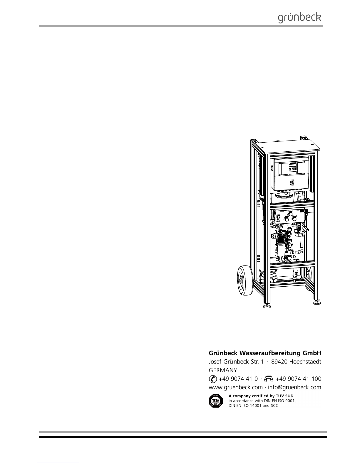
Operation Manual
Mobile reverse osmosis system
AVRO-flex 400
Starting from software version V1.33
Edition November 2018
Order no. 095 752 946-inter
Page 2

Mobile reverse osmosis system
AVRO-flex 400
Order no. 095 752 946-inter Edited by: phar-mrie G:\BA-752946-INTER_095_AVRO-FLEX_400.DOCX
2
Table of contents
AGeneral .................................................................................................................................................................. 5
1 | Preface ..........................................................................................................................................................................................................5
2 | How to use this operation manual .................................................................................................................................................................6
3 | General safety information ............................................................................................................................................................................6
3.1Symbols and notes ..................................................................................................................................................................................6
3.2Operating personnel ...............................................................................................................................................................................7
3.3Intended use ............................................................................................................................................................................................7
3.4Protection from water damage ................................................................................................................................................................7
3.5Indication of specific hazards ..................................................................................................................................................................7
4 | Shipping and storage .....................................................................................................................................................................................8
5 | Disposal .........................................................................................................................................................................................................8
5.1Packaging ................................................................................................................................................................................................8
5.2Product ....................................................................................................................................................................................................8
BBasic information ................................................................................................................................................. 9
1 | Laws, regulations, standards .........................................................................................................................................................................9
2 | Water .............................................................................................................................................................................................................9
3 | Functional principle of reverse osmosis ......................................................................................................................................................10
3.1Functional principle of the AVRO system ..............................................................................................................................................11
CProduct description ........................................................................................................................................... 12
1 | Type designation plate ................................................................................................................................................................................12
2 | Functional description ..................................................................................................................................................................................13
3 | Technical specifications ...............................................................................................................................................................................17
4 | Intended use ................................................................................................................................................................................................18
5 | Application limits ..........................................................................................................................................................................................19
6 | Scope of supply ...........................................................................................................................................................................................20
6.1Standard equipment ..............................................................................................................................................................................20
6.2Optional accessories .............................................................................................................................................................................21
6.3Consumables .........................................................................................................................................................................................22
6.4Wearing parts ........................................................................................................................................................................................22
DInstallation .......................................................................................................................................................... 23
1 | General installation instructions ...................................................................................................................................................................23
1.1Water connection ...................................................................................................................................................................................23
EStart-up................................................................................................................................................................ 24
1 | How to connect the system to the water supply ..........................................................................................................................................24
2 | How to flush the system ..............................................................................................................................................................................26
2.1How to flush off the preserving agent ....................................................................................................................................................26
2.2Filling mode ...........................................................................................................................................................................................26
2.3Workshop mode ....................................................................................................................................................................................28
FOperation (control unit) ..................................................................................................................................... 29
1 | Preface ........................................................................................................................................................................................................29
2 | How to operate the control unit....................................................................................................................................................................30
2.1Reading the operating status ................................................................................................................................................................31
2.2How to set the time ................................................................................................................................................................................31
2.3Access to the programming levels - change parameters ......................................................................................................................32
2.4Software version Code 999 ...................................................................................................................................................................32
3 | Programming levels .....................................................................................................................................................................................33
3.1 Input logic Code 113 .............................................................................................................................................................................33
3.2 System parameters Code 290 ..............................................................................................................................................................33
3.3Reference values / times Code 302 ......................................................................................................................................................34
3.4Error memory / water volumes Code 245 ..............................................................................................................................................35
3.5Diagnosis Code 653 ..............................................................................................................................................................................35
4 | Wiring diagram of mobile reverse osmosis system AVRO-flex 400 ............................................................................................................36
5 | Operation of reverse osmosis system AVRO-flex 400 ................................................................................................................................38
5.1How to set the system recovery ............................................................................................................................................................38
GTroubleshooting ................................................................................................................................................. 40
HMaintenance and care ........................................................................................................................................ 42
1 | Basic information .........................................................................................................................................................................................42
2 | Inspection (functional check) .......................................................................................................................................................................42
3 | Maintenance ................................................................................................................................................................................................43
3.1Operation log .........................................................................................................................................................................................44
4 | Operation log ...............................................................................................................................................................................................45
Maintenance work on mobile reverse osmosis system AVRO-flex 400 .................................................................... 46
Maintenance work on mobile reverse osmosis system AVRO-flex 400 .................................................................... 48
Maintenance work on mobile reverse osmosis system AVRO-flex 400 .................................................................... 50
Page 3

Mobile reverse osmosis system
AVRO-flex 400
Order no. 095 752 946-inter Edited by: phar-mrie G:\BA-752946-INTER_095_AVRO-FLEX_400.DOCX
3
Publisher's information
All rights reserved.
©
Copyright by Grünbeck Wasseraufbereitung GmbH
Printed in Germany
Effective with the date of edition indicated on the cover sheet.
-We reserve the right to modifications, especially with regard to technical progress-
Reprints, translations into foreign languages, electronic storage or
copying only with explicit written approval of Grünbeck Wasseraufbereitung GmbH.
Any type of duplication not authorised by Grünbeck Wasseraufbereitung is a copyright violation and subject to legal action.
Responsible for contents:
Grünbeck Wasseraufbereitung GmbH
Josef-Grünbeck-Str. 1 89420 Hoechstaedt/Germany
Tel. +49 9074 41-0 Fax +49 9074 41-100
www.gruenbeck.com [email protected]
Print: Grünbeck Wasseraufbereitung GmbH
Josef-Grünbeck-Str. 1, 89420 Hoechstaedt/Germany
Page 4
Mobile reverse osmosis system
AVRO-flex 400
Order no. 095 752 946-inter Edited by: phar-mrie G:\BA-752946-INTER_095_AVRO-FLEX_400.DOCX
4
EU Declaration of Conformity
This is to certify that the system designated below meets the safety and health requirements of
the applicable European guidelines in terms of its design, construction and execution.
If the system is modified in a way not approved by us, this certificate is void.
Manufacturer: Grünbeck Wasseraufbereitung GmbH
Josef-Grünbeck-Str. 1
89420 Hoechstaedt/Germany
Responsible for documentation: Markus Pöpperl
System designation: Mobile reverse osmosis system
System type: AVRO-flex 400
Serial no.: Refer to type designation plate
Applicable directives: Machinery Directive (2006/42/EU)
EMC (2014/30/EU)
Applied harmonised standards,
in particular:
DIN EN ISO 12100:2011-03,
DIN EN 61000-6-2:2006-03
DIN EN 61000-6-3:2011-09
Applied national standards
and technical specifications,
in particular:
Place, date and signature: Hoechstaedt, 30.04.2018 i. V._____________
M. Pöpperl
Dipl. Ing. (FH)
Function of signatory: Head of Technical Product Design
Page 5

Mobile reverse osmosis system
AVRO-flex 400
Order no. 095 752 946-inter Edited by: phar-mrie G:\BA-752946-INTER_095_AVRO-FLEX_400.DOCX
5
A General
1 | Preface
Thank you for opting for a Grünbeck product. Backed by decades of
experience in the area of water treatment, we provide customised solutions for all kind of processes.
Drinking water is classified as food and requires particular care.
Therefore, always ensure the required hygiene when operating and
maintaining systems involved in the drinking water supply. This also
applies to the treatment of water for industrial use if repercussions for
the drinking water cannot completely be excluded.
All Grünbeck systems and devices are made of high-quality materials.
This ensures reliable operation over many years, provided you treat
your water treatment systems with the required care. This operation
manual assists you with important information. Therefore, please read
the entire operation manual before installing, operating or maintaining
the system.
Customer satisfaction is our prime objective and providing customers
with qualified advice is crucial. If you have any questions concerning
this system, possible extensions or general water and waste water
treatment, our field staff, as well as the experts at our headquarters in
Hoechstaedt, are available to help you.
Advice and assistance
For advice and assistance please contact your local representative
(see www.gruenbeck.com) or get in touch with our service centre
which can be reached during office hours:
Phone: +49 9074 41-333
Fax: +49 9074 41-120
Email: [email protected]
We can connect you with the appropriate expert more quickly if you
provide the required system data. In order to have the required data
handy at all times, please copy it from the type designation plate to
the overview in Chapter C-1.
Page 6
Mobile reverse osmosis system
AVRO-flex 400
Order no. 095 752 946-inter Edited by: phar-mrie G:\BA-752946-INTER_095_AVRO-FLEX_400.DOCX
6
2 | How to use this operation manual
This operation manual is intended for the operators of our systems. It
is divided into several chapters which are listed in the “Table of contents” on page 2 in alphabetical order. In order to find the specific information you are looking for, check for the corresponding chapter on
page 2.
The headers and page numbers with chapter information make it easier to find your way around in the manual.
3 | General safety information
3.1 Symbols and notes
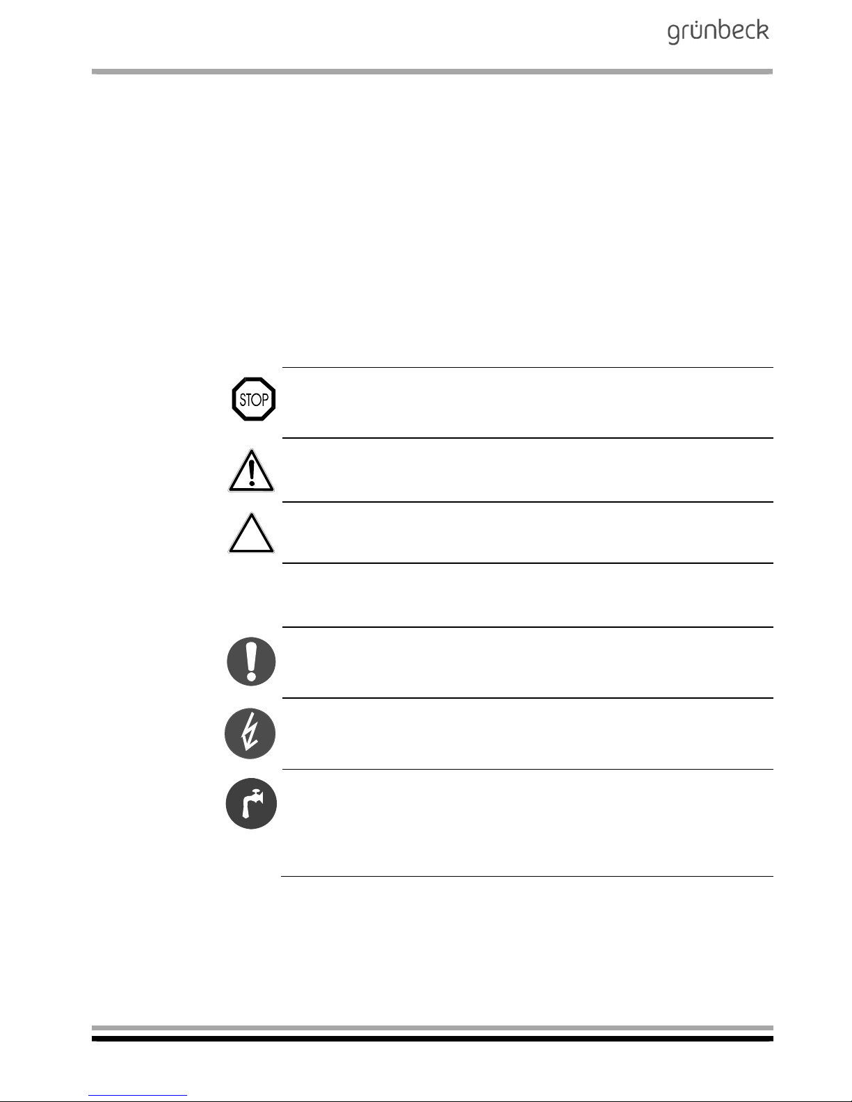
Important information in this operation manual is characterised by
symbols. Please pay particular attention to this information to ensure
the hazard-free, safe and efficient handling of the system.
Danger! Failure to adhere to this information will cause serious or
life-threatening injuries, extensive damage to property or inadmissible contamination of the drinking water.
Warning! Failure to adhere to this information may cause injuries,
damage to property or contamination of the drinking water.
Attention! Failure to adhere to this information may result in damage
to the system or other objects.
Note: This symbol characterises information and tips to make your
work easier.
Tasks with this symbol may only be performed by Grünbeck's technical service/authorised service company or by persons expressly
authorised by Grünbeck.
Tasks with this symbol may only be performed by trained and qualified electrical experts according to the VDE guidelines or according
to the guidelines of a similar local institution.
Tasks with this symbol may only be performed by the local water supply companies or approved installation companies. In Germany, the
installation company must be registered in an installation directory of
a water company as per §12(2) AVBWasserV (German Ordinance on
General Conditions for the Supply of Water).
Page 7
Mobile reverse osmosis system
AVRO-flex 400
Order no. 095 752 946-inter Edited by: phar-mrie G:\BA-752946-INTER_095_AVRO-FLEX_400.DOCX
7
3.2 Operating
personnel
Only persons who have read and understood this operation manual
are permitted to work with the system. The safety information in particular is to be strictly adhered to.
3.3 Intended use
The system may only be used for the purpose outlined in the product
description (Chapter C). The instructions in this operation manual as
well as the applicable local guidelines concerning drinking water protection, accident prevention and occupational safety must be adhered
to.
In addition, intended use also implies that the system may only be operated when it is in proper working order. Any malfunctions must be
repaired at once.
3.4 Protection from water damage
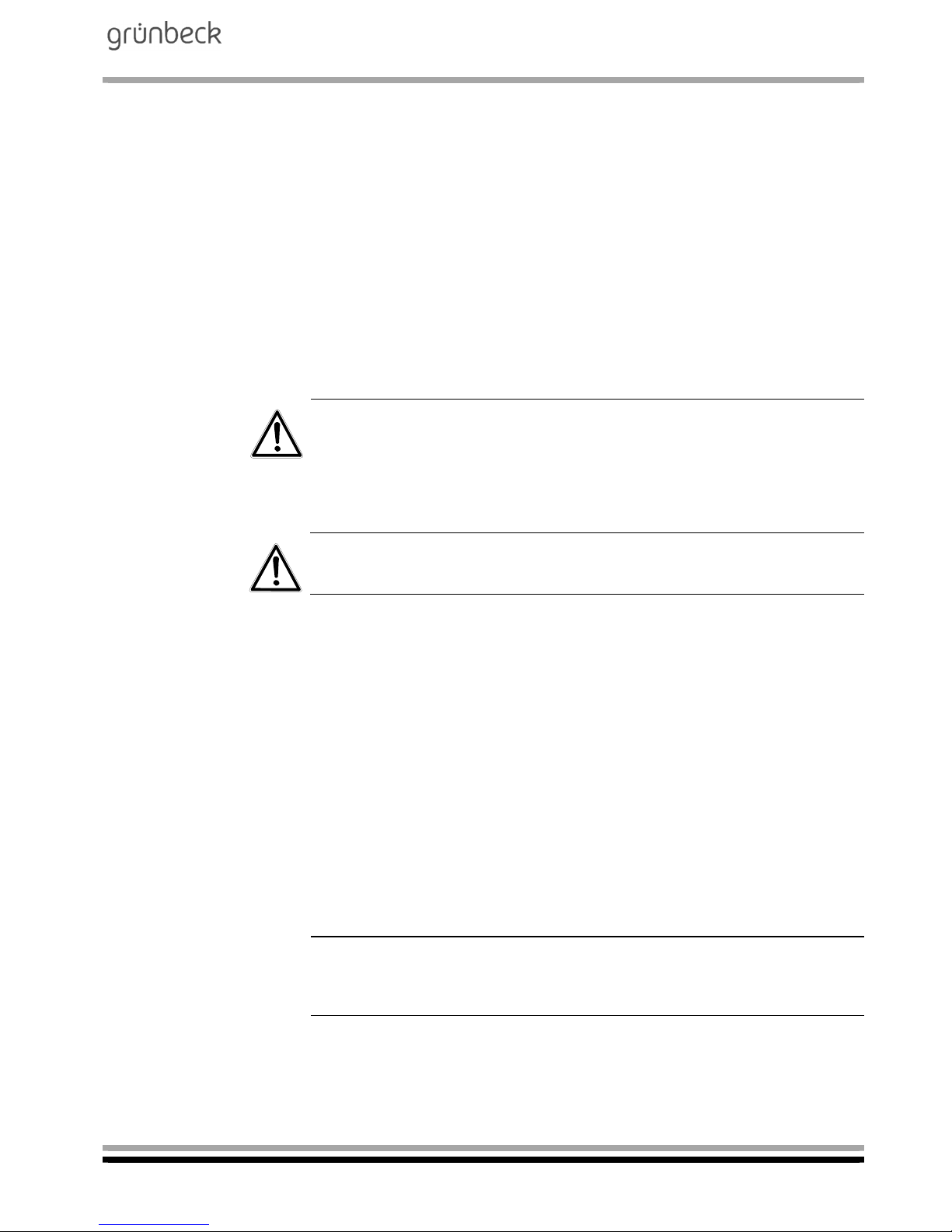
Warning! In order to properly protect the installation site from water
damage:
a. a sufficient floor drain system must be available or
b. a safety device (refer to Chapter C “Optional accessories”) must be
installed.
Warning! Floor drains with discharge to a lifting system do not work
in case of a power failure.
3.5 Indication of
specific hazards
Danger due to electrical energy! Do not touch electrical parts with
wet hands! Unplug the mains plug before starting work on electrical
parts of the system. Have qualified experts replace damaged cables
immediately.
Danger due to mechanical energy! System parts may be subject to
overpressure. Danger of injury and damage to property due to escaping water and unexpected movement of system parts. Check pressure pipes regularly. Depressurise the system before starting repair
or maintenance work on the system.
Hazardous to health due to contaminated drinking water! The system may only be installed by a specialist company. The operation
manual must be strictly adhered to! Ensure that there is sufficient
flow. The pertinent guidelines must be followed for start-up after extended periods of standstill. Inspections and maintenance must be
performed at the intervals specified!
Note: By concluding a maintenance contract, you ensure that all of
the required tasks are performed on time. You may perform the interim inspections yourself.
Page 8
Mobile reverse osmosis system
AVRO-flex 400
Order no. 095 752 946-inter Edited by: phar-mrie G:\BA-752946-INTER_095_AVRO-FLEX_400.DOCX
8
4 | Shipping and storage
Attention! The system may be damaged by frost or high tempera-
tures. In order to avoid damage of this kind:
Protect from frost during transportation and storage!
Do not install or store system next to objects which radiate a lot of
heat.
5 | Disposal
Comply with the applicable national regulations.
5.1 Packaging
Dispose of the packaging in an environmentally sound manner.
5.2 Product
If this symbol (crossed out waste bin) is on the product, European
Directive 2012/19/EU applies to this product. This means that this
product and the electrical and electronic components must not be
disposed of as household waste.
Dispose of electrical and electronic products or components in an
environmentally sound manner.
For information on collection points for your product, contact your
municipality, the public waste management authority, an authorised
body for the disposal of electrical and electronic products or your
waste collection service.
Page 9

Mobile reverse osmosis system
AVRO-flex 400
Order no. 095 752 946-inter Edited by: phar-mrie G:\BA-752946-INTER_095_AVRO-FLEX_400.DOCX
9
B Basic information
1 | Laws, regulations, standards
In the interest of good health, rules cannot be ignored when it comes
to the processing of drinking water. This operation manual takes into
consideration the current regulations and stipulates information that
you will need for the safe operation of your water treatment system.
Among other things, the regulations stipulate that
only approved companies are permitted to make major modifications
to water supply facilities
and that tests, inspections and maintenance on installed devices are
to be performed at regular intervals.
2 | Water
There is no chemically pure water in nature. Even in the atmosphere,
rain water absorbs various substances that change the properties of
the water to a greater or lesser degree. This process continues as the
water passes through the ground layers, with the result that the water
is enriched with increasingly large quantities of materials. Carbon dioxide (CO2) is particularly important here, since this substance increases the dissolving capability of the water even more. Consequently, drinking water contains quantities of dissolved sodium, potassium, calcium, magnesium, iron, manganese, copper, zinc, chlorides,
fluorides, sulphates and also nitrates, nitrites, phosphates and silicates that vary greatly from location to location.
Due to dynamic substance and water cycles, harmful elements,
which are only partly and only slowly biodegradable are increasingly
released into nature. Over time, these elements therefore accumulate
in ground and surface water. Removing them from natural water bodies again represents a particular challenge. Grünbeck rises to this
challenge and aims at generating unpolluted drinking and industrial
water.
The water works provide us with pure drinking water that is suitable
for consumption. However, if the water is to be used for technical purposes, further treatment is frequently required.
Page 10
Mobile reverse osmosis system
AVRO-flex 400
Order no. 095 752 946-inter Edited by: phar-mrie G:\BA-752946-INTER_095_AVRO-FLEX_400.DOCX
10
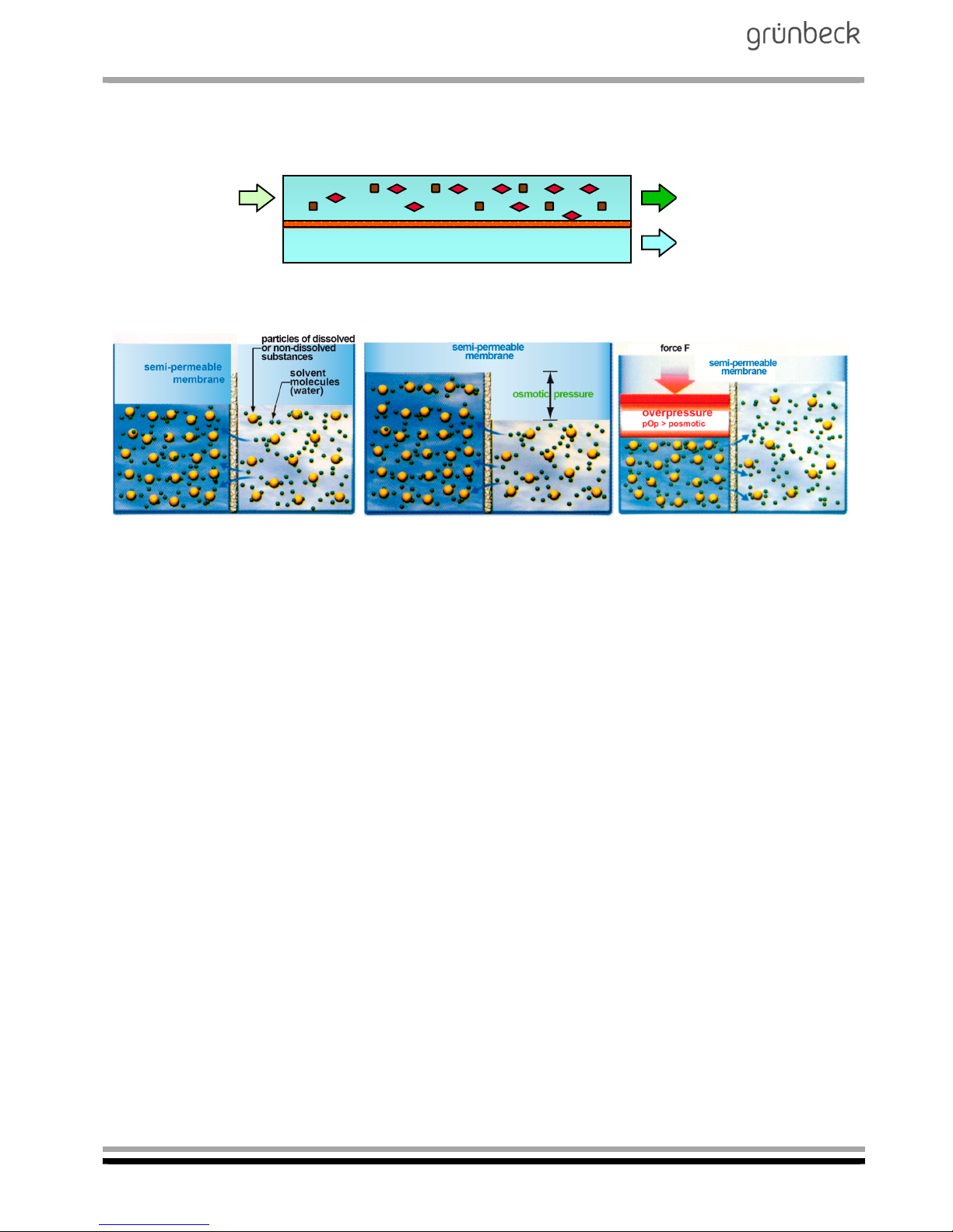
3 | Functional principle of reverse osmosis
Principle:
Pretreated
feed water
Concentrate:
Permeate
Fig. B-1: Functional principle
Solution of high
concentration
Solution of low
concentration
Solution of high
concentration
Solution of low
concentration
Solution of high
concentration
(concentrate)
Solution of low
concentration
(permeate)
Fig. B-2: Reverse osmosis principle
In the osmosis process, watery solutions of different concentrations
are separated by a semi-permeable membrane. In keeping with the
law of nature, the concentrations try to equalise. On the side of the
higher original concentration, the so-called "osmotic" pressure is generated. In case of reverse osmosis, this osmotic pressure is countered by a higher pressure. The consequence: the process proceeds
in the reverse direction. A particular advantage of the reverse osmosis technology compared to other water treatment processes is the
fact that - apart from the removal of dissolved salts - bacteria, germs,
particles and dissolved organic substances are also reduced.
Page 11

Mobile reverse osmosis system
AVRO-flex 400
Order no. 095 752 946-inter Edited by: phar-mrie G:\BA-752946-INTER_095_AVRO-FLEX_400.DOCX
11
3.1 Functional principle of the AVRO
system
AVRO is an alternative anti-scaling process to the common traditional
processes of "softening" or “antiscalant dosing”. Contrary to these
processes, AVRO does not require any addition of auxiliary additives.
The chemical composition of the generated concentrate is not modified. There is only a doubling of the concentration (standard recovery
50 %).
Hydraulically, the AVRO is installed in the concentrate pipe downstream of the membrane.
The treatment unit consists of two inert special electrodes to which a
low current is applied. Seed crystals (calcium carbonate) are generated at the cathode and are permanently directed via the concentrate
recirculation. The salts of the supersaturated concentrate continue to
grow on these seed crystals, and they are finally washed out to the
drain with the residual concentrate flow. This reliably prevents scaling
(deposits of insoluble salts on the membrane). Some of the calcium
carbonate remains on the cathode of the AVRO and due to increasing
electrical resistance, limits the service life of the AVRO treatment unit
to 3000 operating hours (permeate production) or 5 years.
Page 12
Mobile reverse osmosis system
AVRO-flex 400
Order no. 095 752 946-inter Edited by: phar-mrie G:\BA-752946-INTER_095_AVRO-FLEX_400.DOCX
12
C Product description
1 | Type designation plate
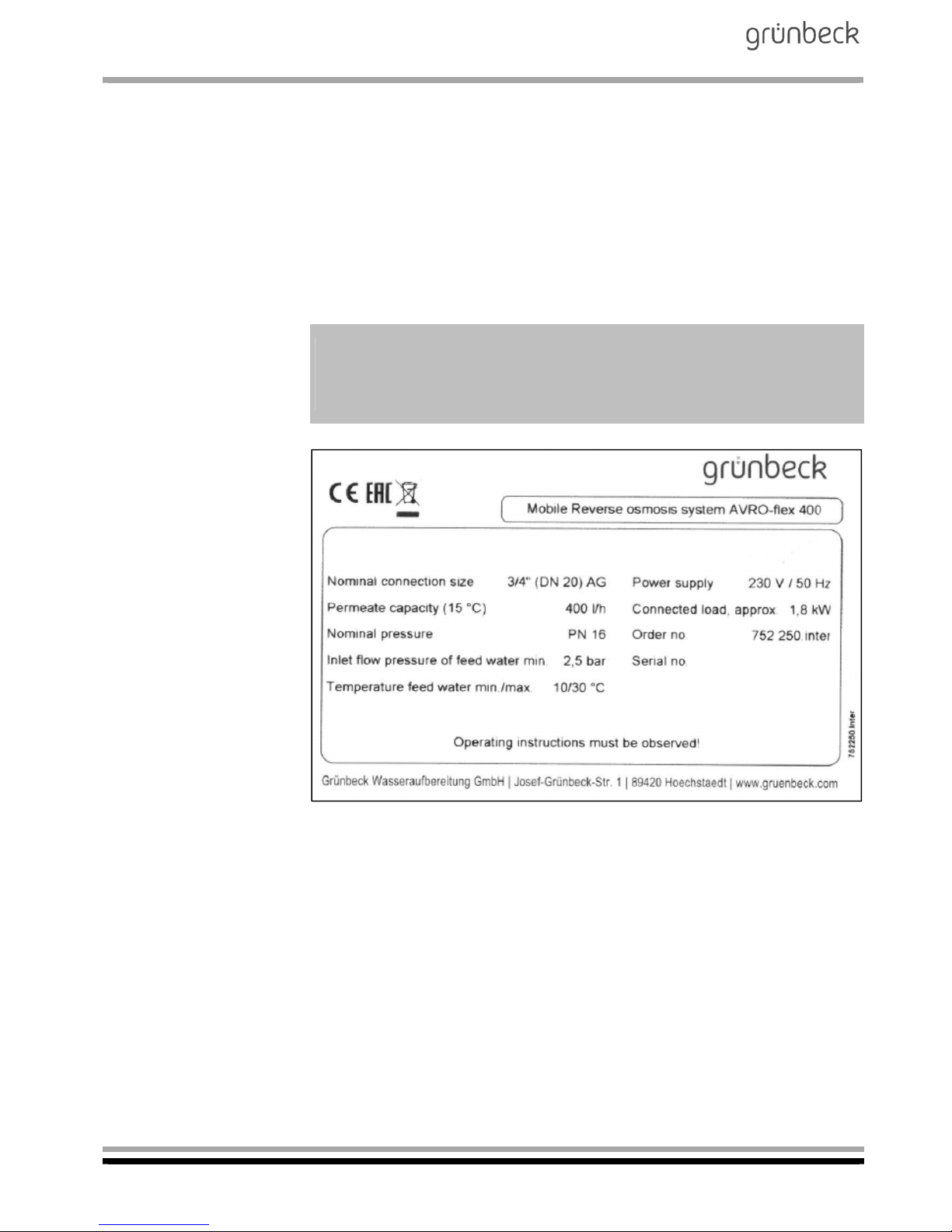
You may find the type designation plate at the housing of the mobile
reverse osmosis system AVRO-flex 400. In order to speed up the processing of your inquiries or orders, please specify the data shown on
the type designation plate of your system when contacting Grünbeck.
Please copy the indicated information to the table below in order to
have it handy whenever necessary.
Mobile reverse osmosis system AVRO-flex 400
Serial number:
Order number:
Fig. C-1: Type designation plate
Page 13

Mobile reverse osmosis system
AVRO-flex 400
Order no. 095 752 946-inter Edited by: phar-mrie G:\BA-752946-INTER_095_AVRO-FLEX_400.DOCX
13
2 | Functional description
Via a fine filter (filter element), the water is directed to the inlet of the
feed water section. The water flows to the high-pressure pump via the
inlet solenoid valve with a downstream “pressure switch for minimum
pressure”. By means of a control valve, the pressure generated by the
high-pressure pump is reduced to the required operating pressure
and the water is directed to the membrane. The membrane separates
the water into the partial flows permeate and concentrate. A partial
flow of the concentrate is returned to the feed water via an orifice regulating independently of pressure and thus ensures a steady flow
over the membrane and increases the economic efficiency of the reverse osmosis.
At the same time, the concentrate volume flow is run via an AVRO
treatment module where seed crystals are formed at a cathode due to
the application of direct current. These seed crystals are then washed
out with the residual concentrate and thus the reverse osmosis membrane is protected from clogging. Whenever the system is switched
off or in case of disturbances, the substances retained on the membrane are flushed off by means of the inlet solenoid valve and a solenoid valve switched in parallel to the control valve for concentrate.
The hydraulic set-up of the system is designed in a way that the concentrate volume and the permeate volume are registered by means of
flow sensors and are displayed in the control unit. The system recovery can also be called up in the control unit.
Downstream of the membrane, the permeate produced can be delivered into the heating system with a counter-pressure of up to 3.5 bar.
Note: If the counter-pressure on the permeate side increases, the
permeate output decreases.
Filling mode:
If "filling mode" is selected via the selector switch on the controller,
three waves are visible in the controller. The pressure switch is interrogated as the start criterion.
Workshop mode:
If "workshop mode" is selected via the selector switch on the control-
ler, one wave is visible in the controller. Selection of the operating
switch is used as the start criterion. After 24 hours, permeate is produced over time. The workshop mode prevents germs from infecting
the system, thereby ensuring a constant permeate quality.
Page 14
Mobile reverse osmosis system
AVRO-flex 400
Order no. 095 752 946-inter Edited by: phar-mrie G:\BA-752946-INTER_095_AVRO-FLEX_400.DOCX
14
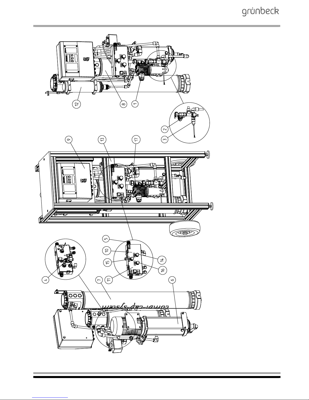
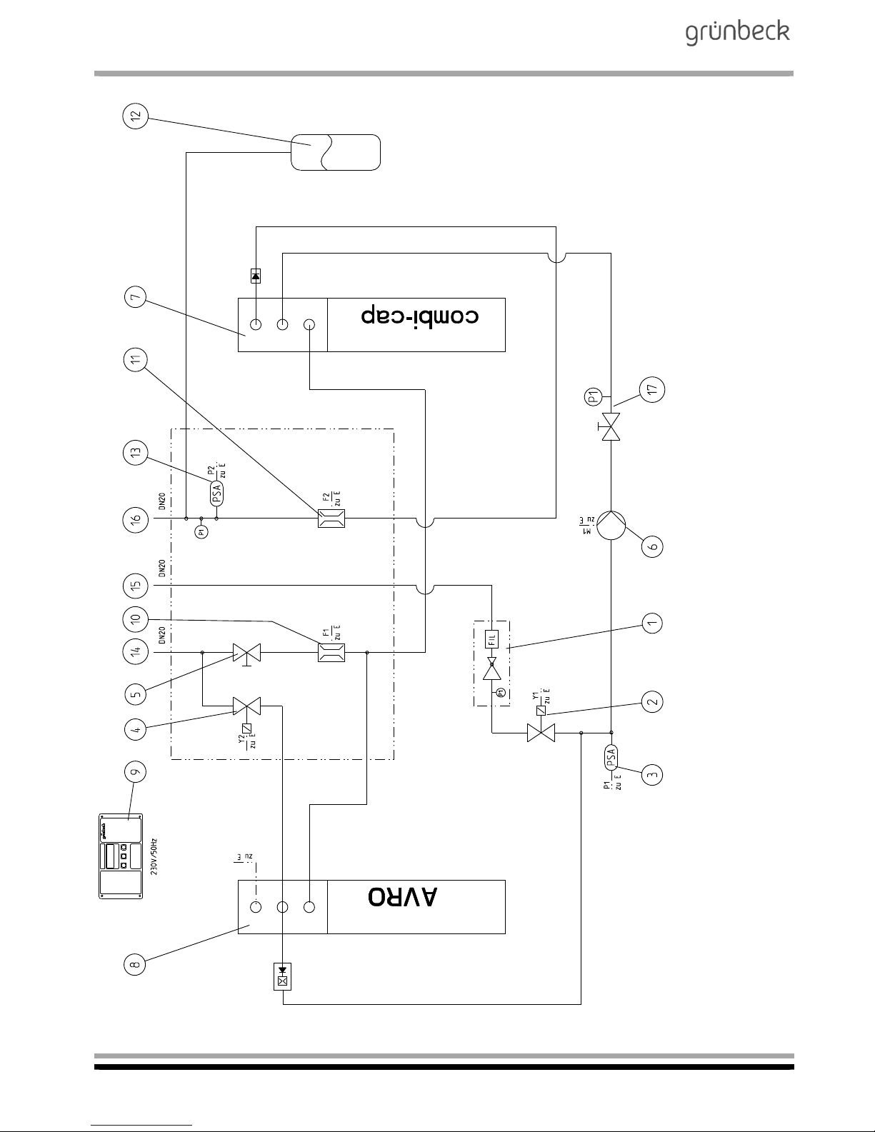
Fig. C-2: Exploded drawing of mobile reverse osmosis system AVRO-flex 400
Page 15

Mobile reverse osmosis system
AVRO-flex 400
Order no. 095 752 946-inter Edited by: phar-mrie G:\BA-752946-INTER_095_AVRO-FLEX_400.DOCX
15
Fine filter incl.
pressure reducer
Pressure reducer preset to 2.5 bar, incl. pressure gauge.
Inlet solenoid valve During the permeate production, this valve is always open. Fol-
lowing the system stop (tank full), the valve remains open for
the programmed flushing time of the membrane. Visual indication in the control unit .
Pressure switch for minimum pressure of highpressure pump.
To prevent the high-pressure pump from running dry. Switches
time-delayed after the solenoid valve has opened . Visual indication in the control unit .
Flushing solenoid valve Opens after the pressure switch “switch-off pressure” has
reached the set pressure. The solenoid valve also opens in the
event of system malfunctions and always in conjunction with the
feed water inlet solenoid valve . Visual indication in the control unit .
Needle valve, concentrate To set the feed water-dependent "concentrate" volume flow to
the drain. During permeate production, this water constantly
flows to the drain.
High-pressure pump Pump unit that generates the required operating pressure for
the membrane and for the filling of heating water systems.
Membrane Reverse osmosis membrane to generate the permeate.
AVRO treatment unit AVRO treatment unit to generate seed crystals.
Control unit Microprocessor controller that in conjunction with the respective
units, regulates the permeate production and the supply of consumers downstream.
Flow sensor, concentrate Records the concentrate volume and sends pulses to the con-
troller. Visual indication of the concentrate volume in the controller .
Flow sensor, permeate Records the permeate volume and sends pulses to the control-
ler. Visual indication of the permeate volume in the controller .
Diaphragm expansion tank Permeate buffer to reduce the switching operations.
Pressure switch switch-off
pressure
Switches the reverse osmosis on when water is required, and
off again after water withdrawal ends.
Connection ¾“ (DN 20)
male thread or GEKA
Concentrate to drain.
Connection ¾“ (DN 20)
male thread or GEKA
Feed water.
Connection ¾“ (DN 20)
male thread or GEKA
Permeate/consumer.
Control valve for operating
pressure with pressure
gauge
To set the operating pressure, with pressure gauge as visual indicator.
1
2
9
3
2
9
4
2
9
5
6
7
8
9
10
9
11
9
12
13
14
15
16
17
Page 16
Mobile reverse osmosis system
AVRO-flex 400
Order no. 095 752 946-inter Edited by: phar-mrie G:\BA-752946-INTER_095_AVRO-FLEX_400.DOCX
16
Fig. C-3: Flow chart of mobile reverse osmosis system AVRO-flex 400
Page 17
Mobile reverse osmosis system
AVRO-flex 400
Order no. 095 752 946-inter Edited by: phar-mrie G:\BA-752946-INTER_095_AVRO-FLEX_400.DOCX
17
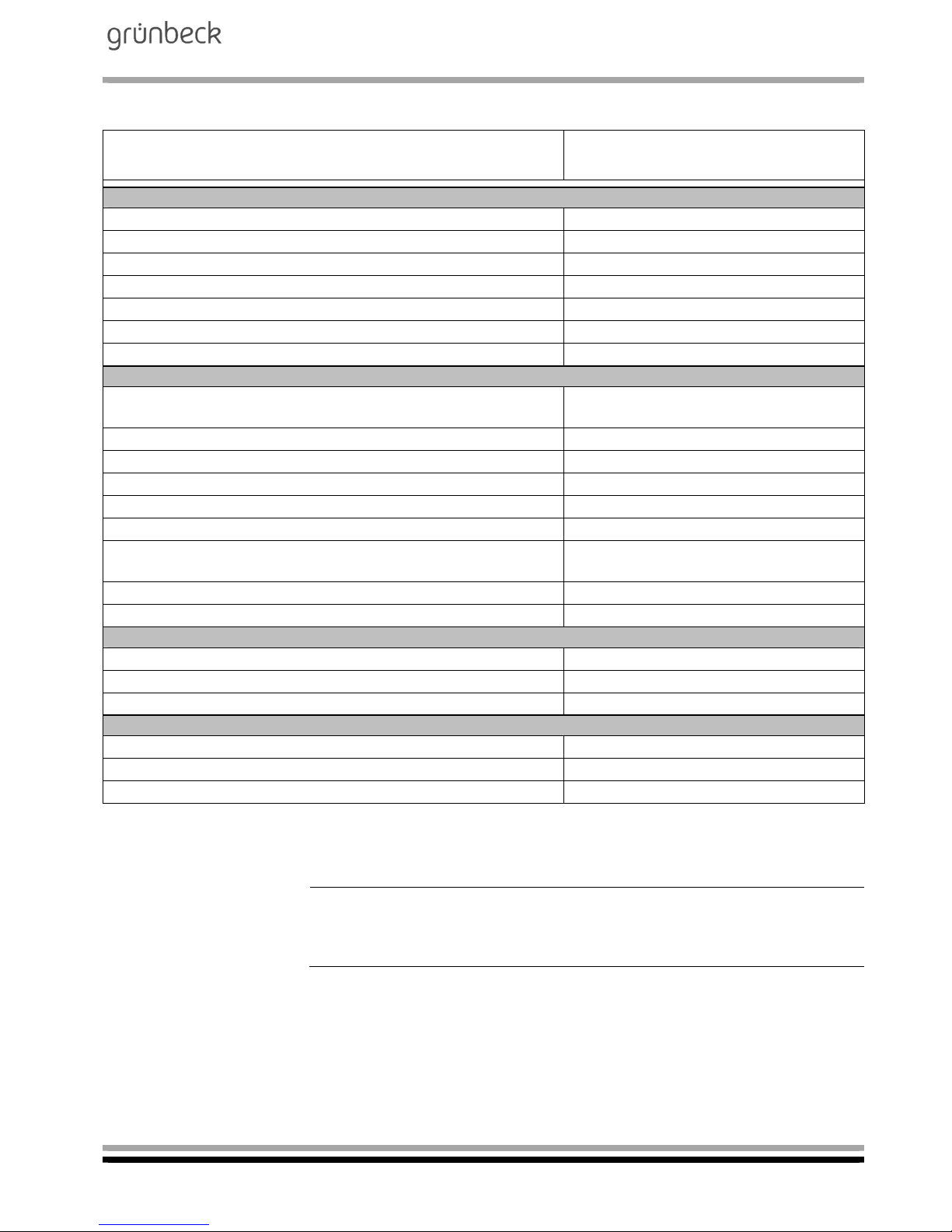
3 | Technical specifications
Table C-1: Technical specifications Mobile reverse osmosis system
AVRO-flex 400
Connection data
Nominal connection diameter of feed water pipe 3/4“ (DN 20) male thread
Nominal connection diameter of permeate outlet 3/4“ (DN 20) male thread
Nominal connection diameter of concentrate outlet 3/4“ (DN 20) male thread
Min. drain connection required DN 50
Connected load, approx. [kW] 1.8
Power supply [V/Hz] 230/50
Protection/protection class IP 54/I
Performance data
Permeate output at
a feed water temperature of 10 °C / 15 °C
[l/h] 340/400
Inlet flow pressure of feed water, min. [bar] 2.5
Nominal pressure PN 16
Salt rejection 95 - 99 %
Total salt concentration of the feed water as NaCl max. [ppm] 1000
Concentrate volume flow (at 15 °C) [l/h] 4001)
Feed water volume flow
(fresh water 15 °C) at a recovery of 50 %, max.
[l/h]
800
Recovery [%] 50
Max. pressure of permeate into the heating system [bar] 3.5
Dimensions and weights
Dimensions (w x d x h) [mm] 700 x 600 x 1450
Empty weight, approx. [kg] 70
Operating weight, approx. [kg] 80
Ambient data
Feed water temperature, min./max. [°C] 10/302)
Ambient temperature, min./max. [°C] 5/35
Order no. 752 250
1)
After a water analysis, the technical service can set a higher recovery.
2)
If the feed water temperature is > 20 °C, special system dimensioning is required.
Note: Based on the permeate output of the reverse osmosis, a max.
pressure of 3.5 bar can be reached. With increasing counter-pressure, the continuous permeate output will decrease.
Page 18

Mobile reverse osmosis system
AVRO-flex 400
Order no. 095 752 946-inter Edited by: phar-mrie G:\BA-752946-INTER_095_AVRO-FLEX_400.DOCX
18
4 | Intended use
The reverse osmosis system AVRO-flex 400 is designed for the de-
mineralisation of drinking water and for the filling of heating systems /
district heating networks and other systems with fully demineralised
water as per the stipulations of VDI 2035, sheets 1 and 2.
If the demineralised water as per VDI 2035 is used to fill systems <
0.11°dH (0.196 °f; 0.0196 mmol/l), it may - subject to the feed water -
be necessary to install a desaliQ:BA mixed bed cartridge downstream.
The continuous permeate output of the system is subject to the temperature and is defined at 15 °C. As the feed water temperature rises
and falls, the permeate outputs can decrease by up to 3% per °C (falling temperature) or rise by the same amount (rising temperature).
The system is adjusted to the permeate requirements to be expected
at the installation site, it is not suitable for major deviations.
The system may only be operated if all components are installed
properly. Safety devices must NEVER be removed, bridged or otherwise tampered with.
Intended use of the device also implies that the information contained
in this operation manual and all safety guidelines applying at the installation site be observed. Furthermore, the maintenance and inspection intervals have to be observed.
The reverse osmosis system AVRO-flex 400 is exclusively designed
for use in the industrial and commercial sector.
4.1 Standstill of the system
If the system is out of operation for more than 14 days, the reverse
osmosis system must be preserved by Grünbeck's technical service/
authorised service company. The maximum time, the system can remain in the preserved condition is 6 months.
In case the downtime is longer, the system must be preserved again
in regular intervals by Grünbeck's technical service/authorised service
company. Prior to resuming operation, the preserving agent must be
flushed from the system.
Page 19
Mobile reverse osmosis system
AVRO-flex 400
Order no. 095 752 946-inter Edited by: phar-mrie G:\BA-752946-INTER_095_AVRO-FLEX_400.DOCX
19
5 | Application limits
With regard to the application of the mobile reverse osmosis system
AVRO-flex 400, the limit values for admissible substances contained
in water which are stipulated in the German Drinking Water Ordinance do represent the upper limits for the system.
< 22° dH (39.2 °f; 3,92 mmol/l) without water analysis
Free chlorine not detectable
Iron < 0.10 mg/l
Manganese < 0.05 mg/l
Silicate < 15 mg/l
Chlorine dioxide not detectable
Turbidity < 1 FTU
Colloid index < 3
pH range 3 - 9
A water analysis is required in case of a total hardness > 22 °dH or
sulphate > 500 mg/l.
Note: The permeate originating from the reverse osmosis system is
not potable but requires additional treatment (blending, hardening) if it
is to be used as drinking water.
Attention! In case of an admissible excess of the sulphate concentration due to geogenic conditions, the recovery with regard to the standard settings according to layout might need to be reduced.
Page 20

Mobile reverse osmosis system
AVRO-flex 400
Order no. 095 752 946-inter Edited by: phar-mrie G:\BA-752946-INTER_095_AVRO-FLEX_400.DOCX
20
6 | Scope of supply
6.1 Standard equipment
Mobile, stand-alone aluminium rack to house all aggregates and
control elements.
Microprocessor controller with LC display, voltage-free collective
fault signal and voltage-free signal contact (maintenance interval,
various pre-warnings), installed in a switch cabinet. Selector switch
for operating modes - filling mode - workshop mode.
Centrifugal pump made of stainless steel with motor as high pres-
sure pump to supply the membrane, incl. control valve for operating
pressure and pressure gauge.
Adjustable pressure switch and diaphragm expansion tank to sup-
ply consumers downstream.
Hydro distributor block for the water supply within the membrane
system. Integrated valves and measuring instruments for easier
system calibration.
Fine filter with integrated pressure reducer, preset to 2.5 bar.
Ultra-low pressure reverse osmosis membranes incl. pressure pipe.
AVRO treatment unit, installed in a pressure pipe made of high-
strength PE.
Flow sensor to measure the volume of the system flows permeate
and concentrate.
Two pressure-resistant, metal fabric hoses and GEKA couplings.
¾" double nipple for connection to a desliQ:BA mixed bed cartridge.
Operation manual.
Page 21
Mobile reverse osmosis system
AVRO-flex 400
Order no. 095 752 946-inter Edited by: phar-mrie G:\BA-752946-INTER_095_AVRO-FLEX_400.DOCX
21
6.2 Optional accessories
Note: It is possible to retrofit existing systems with optional components. Please contact your local Grünbeck representative or
Grünbeck’s headquarters in Hoechstaedt for more information.
Order no.
The safety device protectliQ:A20
is a product to protect one- and two-family
homes from water damage.
For more sizes, please inquire.
126 400
GENO-therm filling device Basic
Consisting of: Dirt trap, shut-off flap, system
separator acc. to DIN EN 1717, adjustable pressure reducer (0.2 - 4 bar), water meter, housing
insulation and fastening material.
707 120
Filling group
Consisting of: Dirt trap for coarse dirt, shut-off
flap, system separator, pressure reducer, nonreturn valves.
707 700
desaliQ:BA mixed bed cartridge
Mixed bed cartridge for full demineralisation
(max. 400 l/h) by means of ion exchange, installed downstream of the AVRO-flex 400.
707 450
(for larger capaci-
ties, please inquire)
GENO-therm filling cartridge 110
Full demineralisation cartridge for full demineralisation by means of ion exchange, installed
downstream of the AVRO-flex 400.
707 150
Drain connection DN 50 acc. to DIN EN 1717
Connection material for DIN-compatible waste
water connection DN 50
187 840
Page 22
Mobile reverse osmosis system
AVRO-flex 400
Order no. 095 752 946-inter Edited by: phar-mrie G:\BA-752946-INTER_095_AVRO-FLEX_400.DOCX
22
6.3 Consumables
Only use genuine consumables in order to ensure the reliable operation of the system.
Order no.
GENO-replacement filter element
with protective cylinder
Packing unit: 2 pcs
103 061
Reverse osmosis membrane
Packing unit: 1 pc
752 685e
AVRO treatment unit with seals
Packing unit: 1 pc
720 050
Water test kit "Total hardness“
Packing unit: 1 pc
170 187
Water test kit "Carbonate hardness“
Packing unit: 1 pc
170 169
6.4 Wearing parts
Seals and valves are subject to a certain wear and tear. Wearing
parts are listed below.
Note: Although these parts are wearing parts, we grant a limited warranty period of 6 months.
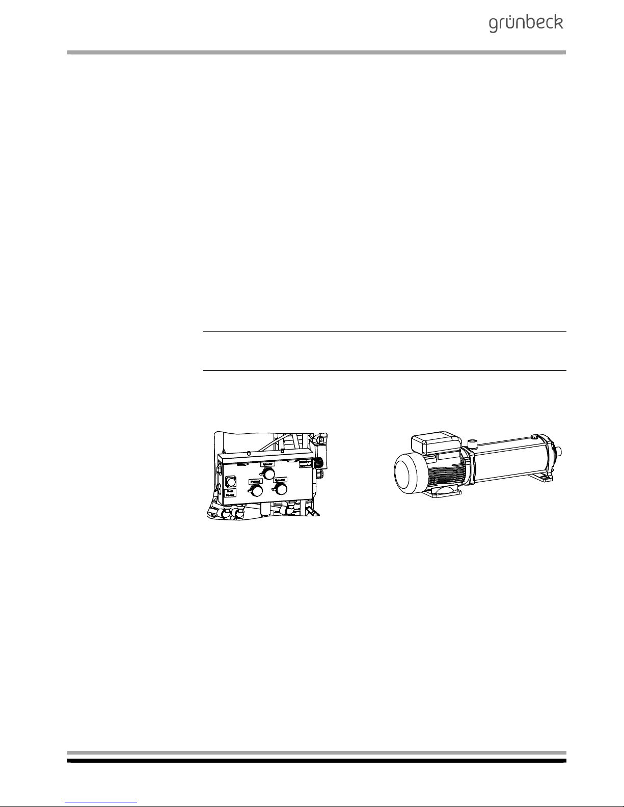
a. Solenoid valves, control valve for concentrate, seals
b. High-pressure pump
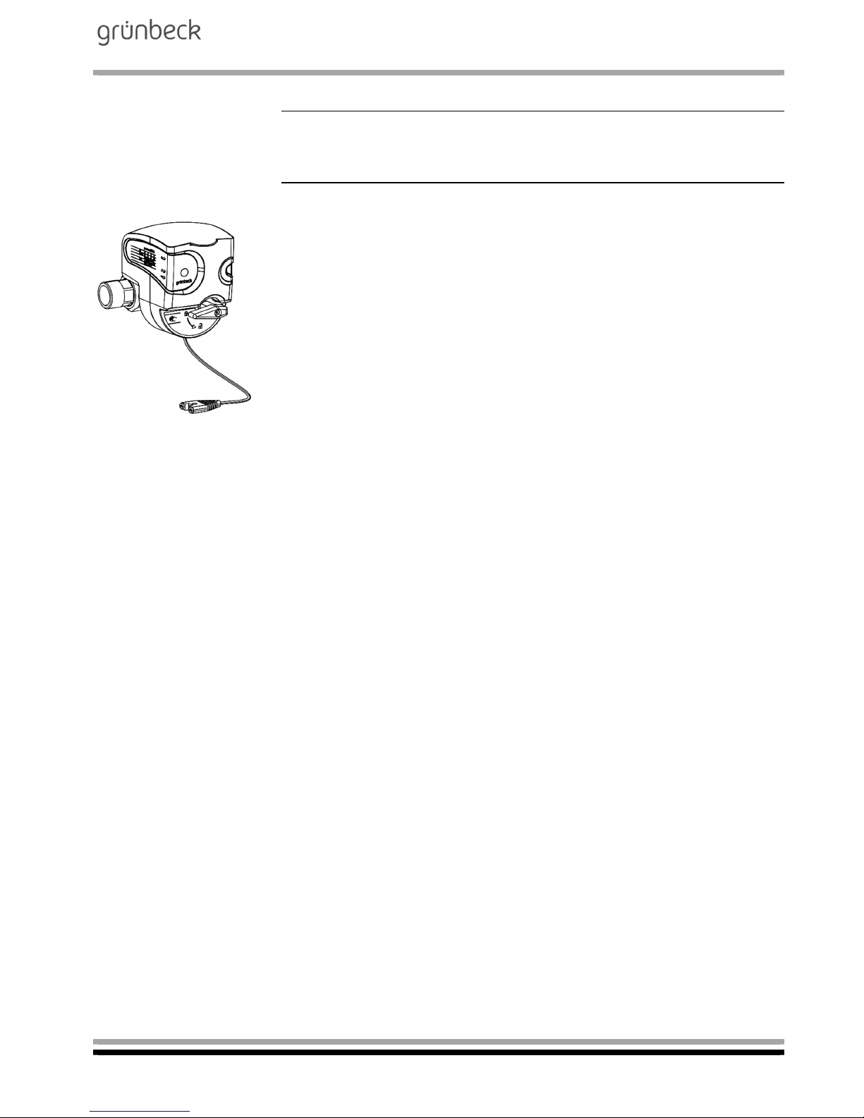
Fig. C-4: Valves Fig. C-5: High-pressure pump
Page 23
Mobile reverse osmosis system
AVRO-flex 400
Order no. 095 752 946-inter Edited by: phar-mrie G:\BA-752946-INTER_095_AVRO-FLEX_400.DOCX
23
D Installation
1 | General installation instructions
The installation site must provide adequate space. A foundation of a
sufficient size and adequate load carrying capacity has to be provided. The required connections must be provided prior to the installation of the system. For dimensions and connection data, please refer
to table C-1.
Note: For the installation of systems with optional accessories (refer
to Chapter C, item 6.3), also observe the operation manuals supplied
with these components.
1.1 Water connection
Certain binding rules must always be observed when installing a mobile reverse osmosis system AVRO-flex 400. Additional recommendations are given in order to facilitate the handling of the system. The installation instructions described below are also illustrated in fig. E-2.
Binding rules
The installation of a mobile reverse osmosis system AVRO-flex 400
represents a major interference with the drinking water system.
Therefore, only authorised experts may install such systems.
Observe local installation guidelines and general regulations.
Install a drinking water filter (e. g. BOXER KD) upstream of the sys-
tem.
Install a system separator upstream – not required when using a
GENO-therm filling device.
Install an activated carbon filter upstream, if required.
Provide a drain connection (minimum DN 50) to discharge the con-
centrate.
Note: If the concentrate is directed to a lifting system, the delivery
rate of the lifting system should at least be 800 l/h.
Warning! The installation site must have a floor drain. If no floor drain
is available, an adequate safety device needs to be installed (refer to
Chapter C, item 6.3 “Optional accessories”).
Warning! Floor drains that discharge to a lifting system do not work in
case of a power failure.
Recommendation
If the mobile reverse osmosis system AVRO-flex 400 is not connected
to the optional filling device GENO-therm, a sampling valve should be
installed directly upstream and downstream of the mobile reverse osmosis system AVRO-flex 400. This simplifies the sampling for the regular quality control (functional check).
Page 24

Mobile reverse osmosis system
AVRO-flex 400
Order no. 095 752 946-inter Edited by: phar-mrie G:\BA-752946-INTER_095_AVRO-FLEX_400.DOCX
24
E Start-up
The work described below may only be performed by trained experts.
We recommend having Grünbeck‘s technical service/authorised service company start up the system.
1 | How to connect the system to the water supply
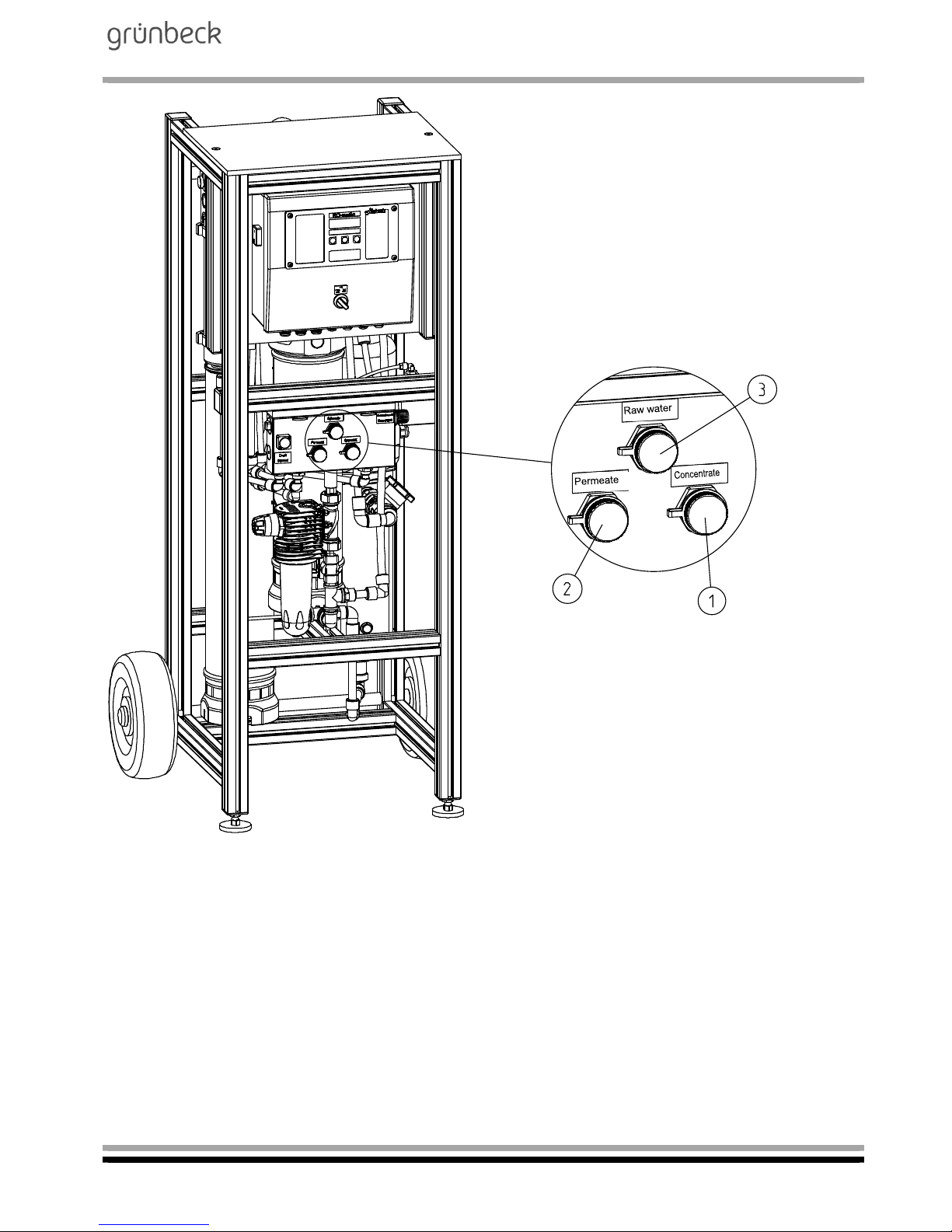
Connect the feed water / raw water hose to the system
(refer to fig. E-1, item 3).
Connect the permeate hose to the system and to the system to be
filled (refer to fig. E-1, item 2).
Connect the concentrate hose to the system (refer to fig. E-1, item
1). Run the hose with a gradient to the drain and connect in accordance with EN 1717 (free outlet).
Page 25
Mobile reverse osmosis system
AVRO-flex 400
Order no. 095 752 946-inter Edited by: phar-mrie G:\BA-752946-INTER_095_AVRO-FLEX_400.DOCX
25
Fig. E-1: Connections of mobile reverse osmosis system AVRO-flex 400
Page 26
Mobile reverse osmosis system
AVRO-flex 400
Order no. 095 752 946-inter Edited by: phar-mrie G:\BA-752946-INTER_095_AVRO-FLEX_400.DOCX
26
2 | How to flush the system
For the duration of storage and transport, the membrane is protected
by means of a preserving agent. This preserving agent must be
flushed off before starting up the system for the first time. To do so,
the concentrate hose (refer to fig. E-1, item 1) and the permeate hose
(refer to fig. E-1, item 2) have to be routed to the drain.
2.1 How to flush off the preserving agent
Note: For more detailed information on the handling of the control
unit, refer to Chapter F.
Switch on the mains switch and switch the operating mode selector
switch to the "OFF" position.
Open both solenoid valves ("DEAERATE") via Code 113, parameter
EnL: 1 and flush off the preserving agent from the system for a duration of 30 min. To do so, open parameter with P button, set ENL: 1
with ▲ button and confirm with P button.
Complete program step “DEARATE”: Open parameter with P button,
set EnL:0 with ▼ button and confirm with P button.
Exit the “EnL” program by simultaneously pressing the buttons ▼and
▲.
2.2 Filling mode
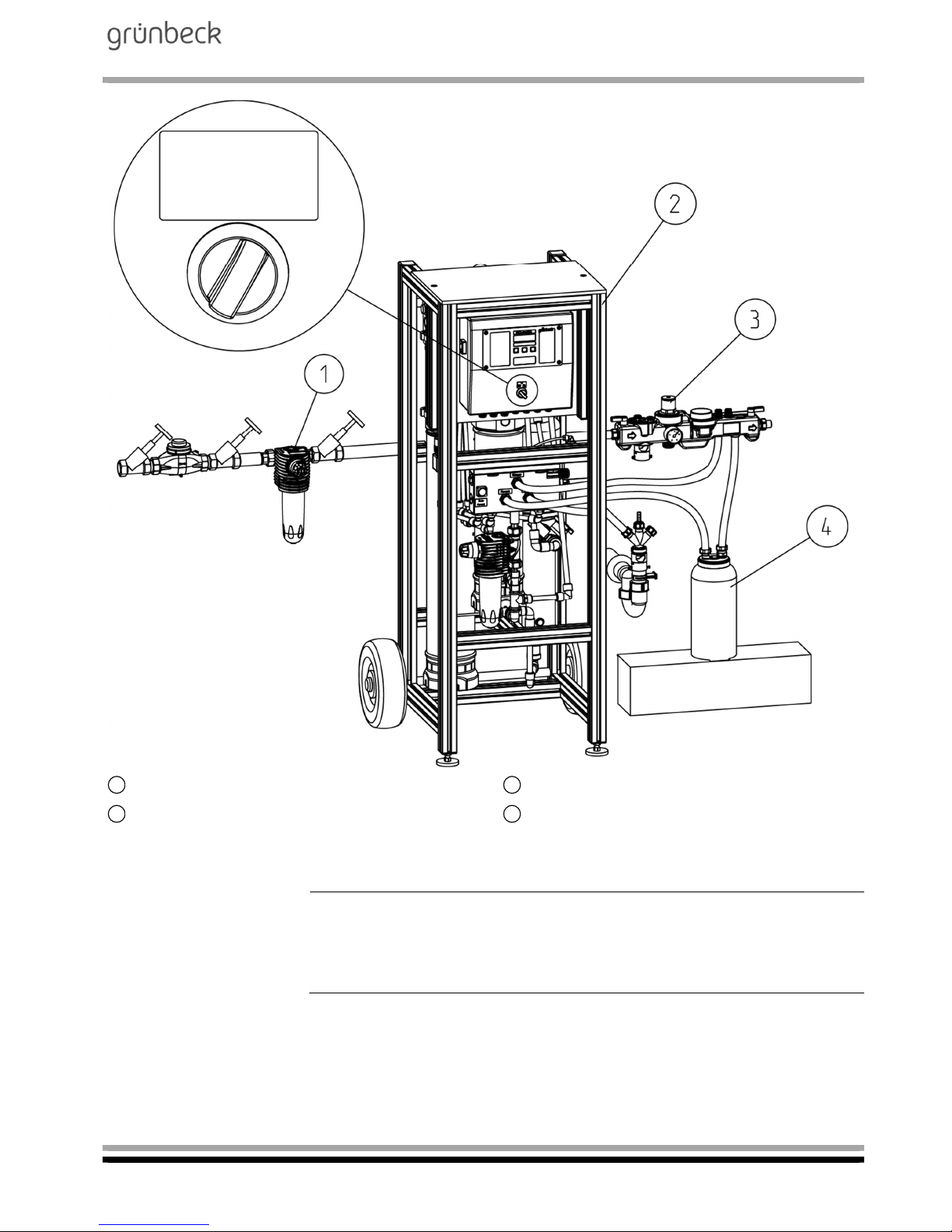
In filling mode (refer to fig. E-2), e.g. heating / cooling water
systems, direct the hose supplied with the system from the
permeate connection of the reverse osmosis system to the filling
valve or to the GENO-therm filling device.
The pressure switch is set to a switch-off pressure of 2.5 bar
= system pressure. If a higher or lower system pressure is required,
this can be set via the pressure switch (refer to fig. C-2, item 13).
Then switch on the reverse osmosis system via the selector switch at
the controller housing. The system produces permeate. Close the filling valve and monitor at which pressure the system switches off. Use
the adjusting screws to set to the desired switch-off pressure/system
pressure.
Note: Based on the permeate output of the reverse osmosis, a max.
pressure of 3.5 bar can be reached. With an increasing counter-pressure, the continuous permeate output will decrease.
Page 27
Mobile reverse osmosis system
AVRO-flex 400
Order no. 095 752 946-inter Edited by: phar-mrie G:\BA-752946-INTER_095_AVRO-FLEX_400.DOCX
27
Drinking water filter BOXER KD (option)
GENO-therm filling device Basic (option)
Mobile reverse osmosis system AVRO-flex
GENO-therm filling cartridge (option)
1)
Fig. E-2: Installation drawing of mobile reverse osmosis system AVRO-flex 400 - filling mode
1)
Note: If the demineralised water as per VDI 2035 is used to fill systems < 0.11°dH (0.196 °f; 0.0196 mmol/l), it may – subject to the feed
water – be necessary to install a GENO-therm filling cartridge 110
(order no. 707 150) downstream.
1 3
2 4
Off
Workshop Filling
mode
mode
Page 28
Mobile reverse osmosis system
AVRO-flex 400
Order no. 095 752 946-inter Edited by: phar-mrie G:\BA-752946-INTER_095_AVRO-FLEX_400.DOCX
28
2.3 Workshop mode
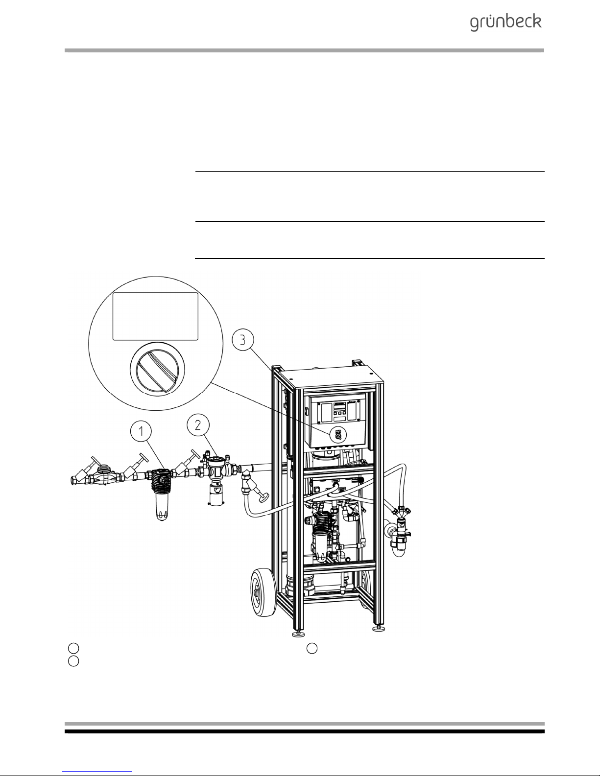
To prevent damage to the membrane due to germs (bio-fouling), the
mobile reverse osmosis system AVRO-flex 400 must be run in workshop mode during the entire periods of standstill (refer to fig. E-3). In
this case, the permeate line as well as the concentrate line are connected as per DIN EN 1717. In the workshop mode, water is rejected
for a certain time set in the controller (factory setting 15 min.) every
day.
Note: The system must be connected to the power supply as well as
to the water/waste water network for the entire period of standstill
(transports up to 48 h excluded).
Note: If installed, the shut-off valve on the permeate side must be
open!
BOXER KD
Mobile reverse osmosis system AVRO-flex 400
Euro system separator GENO-DK 2-Mini
Fig. E-3: Installation drawing of mobile reverse osmosis system AVRO-flex 400 - workshop mode
1
3
2
Off
Workshop Filling
mode
mode
Page 29
Mobile reverse osmosis system
AVRO-flex 400
Order no. 095 752 946-inter Edited by: phar-mrie G:\BA-752946-INTER_095_AVRO-FLEX_400.DOCX
29
F Operation (control unit)
1 | Preface
Note: Instructions in bold are absolutely essential to ensure that work
can continue. All other instructions can be ignored if the value shown
in the display remains unchanged.
Settings in the technical service programming level may only be performed by Grünbeck's technical service/authorised service company
or by persons expressly authorised by Grünbeck.
Warning! Incorrect settings may lead to hazardous operating conditions which cause injury, health problems or damage to property.
The operation manual must be strictly adhered to! Only make the settings described there!
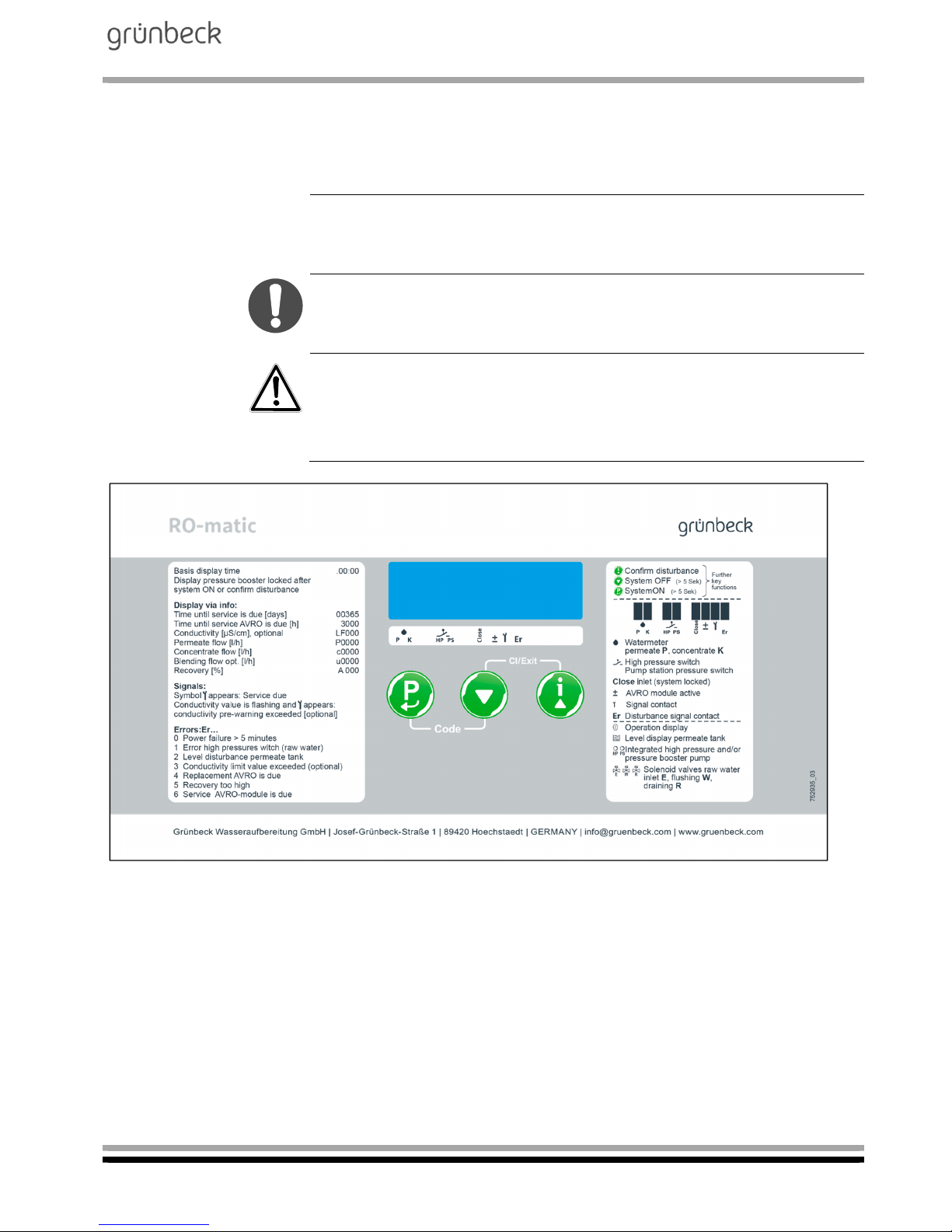
Fig. F-1: Control unit
Page 30
Mobile reverse osmosis system
AVRO-flex 400
Order no. 095 752 946-inter Edited by: phar-mrie G:\BA-752946-INTER_095_AVRO-FLEX_400.DOCX
30
2 | How to operate the control unit
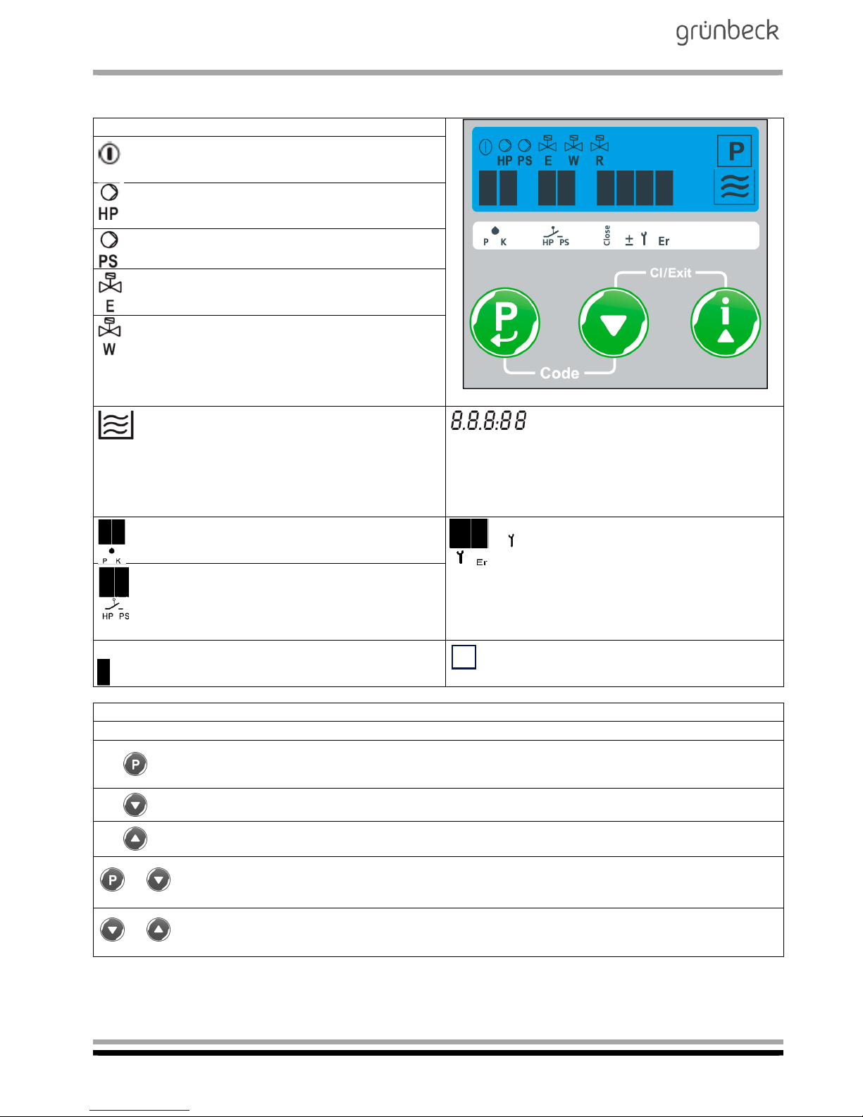
Symbols displayed:
Fig. 2 Operating panel, control unit AVRO-flex 400
Operation indicator
Appears when the system is switched on via the
selector switch (workshop or filling mode)
High-pressure pump
Appears when the high-pressure pump produces
permeate.
Appears, without action/function
Inlet solenoid valve (feed water)
Appears when permeate is being produced or
during system flushing.
Flushing solenoid valve
Appears when the system flushing is in progress
Indication of operating mode
Top wave: system runs in filling mode
Bottom wave: system runs in workshop mode
No wave: system is switched off
Numeric display
Indicates the time and operating pa-
rameters in the Info level
Indicates the parameters of the Code
levels
Indicates symbols in addition to the
fault message
Bars for water meter pulses
Flash with every 5th pulse of the water meters for
permeate or concentrate
Bars for signal and fault signal contact
appears when the maintenance interval has
elapsed
Er appears with all malfunctions Er0, Er1, Er4
and Er8
Indicates the state of the pressure switch for mini-
mum pressure (bar appears when there is pressure) and operational release (bar appears when
permeate is being delivered into the heating system)
±
AVRO treatment module is active (always at the
same time permeate is being delivered into the
heating system)
Flashes when the pressure switch for minimum pressure drops out during permeate production (lack of feed water pressure)
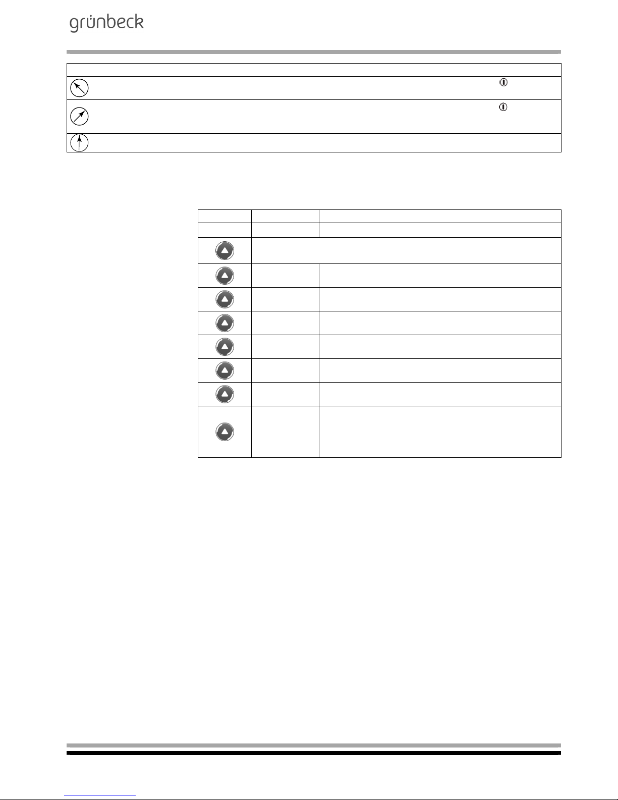
Function of buttons
Basic function: Extended function in programming levels:
Acknowledgement of malfunctions.
Access to time programming
(keep button pressed > 2.5 sec).
Open parameter for editing (value is flashing).
Save and close parameter.
Decrease numerical value.
Return to previous menu item.
Display operating values of Info
level.
Increase numerical value.
Go to the next menu item.
+
Access to the code-protected programming levels
(Code request C 000).
+
Close open parameters without saving
(previous value is maintained).
Return to basic display time.
P
Page 31
Mobile reverse osmosis system
AVRO-flex 400
Order no. 095 752 946-inter Edited by: phar-mrie G:\BA-752946-INTER_095_AVRO-FLEX_400.DOCX
31
Operating modes selector switch
Workshop mode
When the system is switched on (symbol ), permeate
is produced for 15 minutes at the same time every day.
Filling mode
When the system is switched on (symbol l ), it pro-
duces subject to the pressure switch for operational release.
Off
2.1 Reading the
operating status
Various operating parameters can be displayed within the Info level.
The Info level is accessed by pressing the ▲ button.
Button Display Parameters
00:00 Basic display, time
Pressing this button for the first time switches the system on, if
still necessary!
365 Remaining time of maintenance interval [d]
3000 Remaining time of AVRO maintenance interval [h]
P0200 Permeate flow [l/h]
c0200 Concentrate flow [l/h]
A 050 System recovery [%]
l.200 Actual current of AVRO treatment module [mA]
S00.00 Sum of permeate [m³] during filling mode for bill-
ing. Counter reading is deleted again in this display by the combination of buttons P and
▲
(> 5 sec).
2.2 How to set the
time
Requirement:
The basic display time is currently being indicated.
1. Press button P for > 2.5 seconds. Only the hours 00: will still be displayed
2. Press P button to change the hours (value is flashing, now set the
desired value with buttons ▼ or ▲ and save with the P button)
or
press▲ button to advance to the minutes :00
3. Press P button to change the minutes (value is flashing, now set the
desired value with buttons ▼ or ▲ and save with the P button)
4. Return to the basic display time by simultaneously pressing buttons
▼ and▲
Page 32
Mobile reverse osmosis system
AVRO-flex 400
Order no. 095 752 946-inter Edited by: phar-mrie G:\BA-752946-INTER_095_AVRO-FLEX_400.DOCX
32
2.3 Access to the programming levels change parameters
1. Simultaneously pressing the buttons P and ▼ (> 1 sec) causes the
code request C 000 to appear.
2. Set the required code with buttons ▼ or ▲ and confirm with P button.
3. Within the programming level, select the desired parameter with
buttons ▼ or ▲and open it for editing with the P button (value starts
flashing).
4. Change the parameter setting to the desired value with buttons
▼ or ▲ .
5. Save the new parameter setting with the P button (value stops
flashing) or reject the change by simultaneously pressing the buttons ▼ and ▲, and close the parameter again (value stops flashing,
previous setting remains saved).
6. Return to the basic display time by simultaneously pressing buttons
▼ and ▲.
7. If no button is pressed within a parameter level for more than 5
minutes, the system automatically returns to the basic display time.
Any open parameters (value flashing) are closed and the previously
saved value is kept.
2.4 Software version Code 999
Display Parameters
P1.25 Software version of RO-matic controller
Page 33
Mobile reverse osmosis system
AVRO-flex 400
Order no. 095 752 946-inter Edited by: phar-mrie G:\BA-752946-INTER_095_AVRO-FLEX_400.DOCX
33
3 | Programming levels
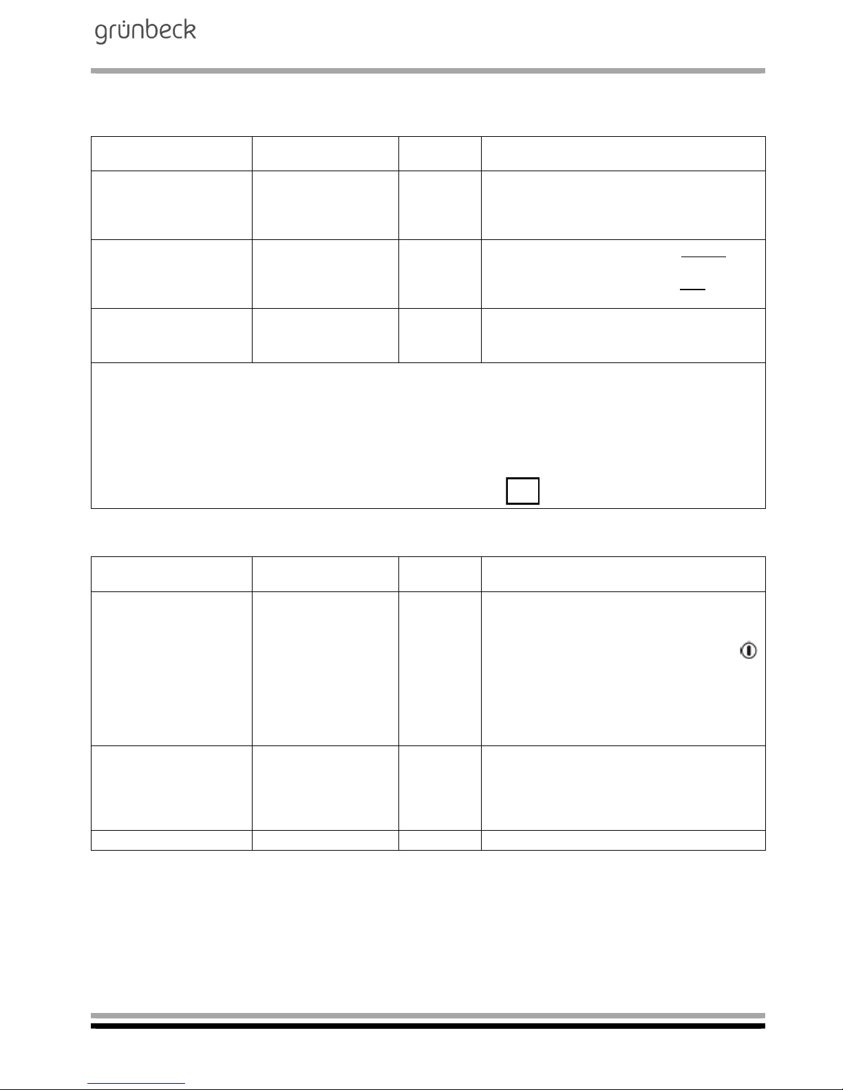
3.1 Input logic Code 113
Display / factory
setting
Parameters Setting
range
Comment
EHP: 2 Type of contact
Pressure switch for
minimum pressure
(high-pressure pump)
0 ... 3 0 = Normally open contact (NOC)
1 = Normally closed contact (NCC)
2 = NOC with automatic restart
1)
3 = NCC with automatic restart
1)
EPS: 1 Type of contact
PS pressure switch
0 ... 1 0 = NOC (setting for systems without
pressure switch
1 = NCC (setting for systems with
pressure switch)
EnL: 0 Flush system (inlet
and flushing solenoid
valves)
0 ... 1 1 = Open solenoid valves (only possible
if the system is switched off)
0 = Close solenoid valves again
1)
If error Er 1 occurs during ongoing permeate production (pressure switch minimum pressure of
high-pressure pump), the system attempts a restart at the following intervals:
5 ... 10 ... 20 ... 40 ... 80 ... 160 minutes
If sufficient pressure is present, permeate is produced until the pressure switch for operational
release responds and the error is acknowledged automatically.
During the wait time between the start attempts, the symbol is flashing in the display.
3.2 System parameters Code 290
Display / factory
setting
Parameters Setting
range
Comment
5. 2 Reaction to return of
power for error Er 0
(power failure > 5
minutes)
0 ... 2 0 = Irrespective of whether the system was
switched on or off prior to the power failure,
it remains switched off after power is restored and error Er 0 is emitted (symbol
is still switched on)
1 = Error Er 0 is deactivated
2 = After power is restored, the system is
switched on or off like prior to the
power failure, and error Er 0 is emitted
D. 15 Run time of work-
shop mode [minutes]
15 ... 99 In workshop mode, permeate is produced
for this time at a 24 h interval after the system is switched on. Operation is irrespective of the status of the pressure switch for
operational release.
E. 0 Reserved function 0 .... 1 0 = Factory setting
P
Page 34
Mobile reverse osmosis system
AVRO-flex 400
Order no. 095 752 946-inter Edited by: phar-mrie G:\BA-752946-INTER_095_AVRO-FLEX_400.DOCX
34
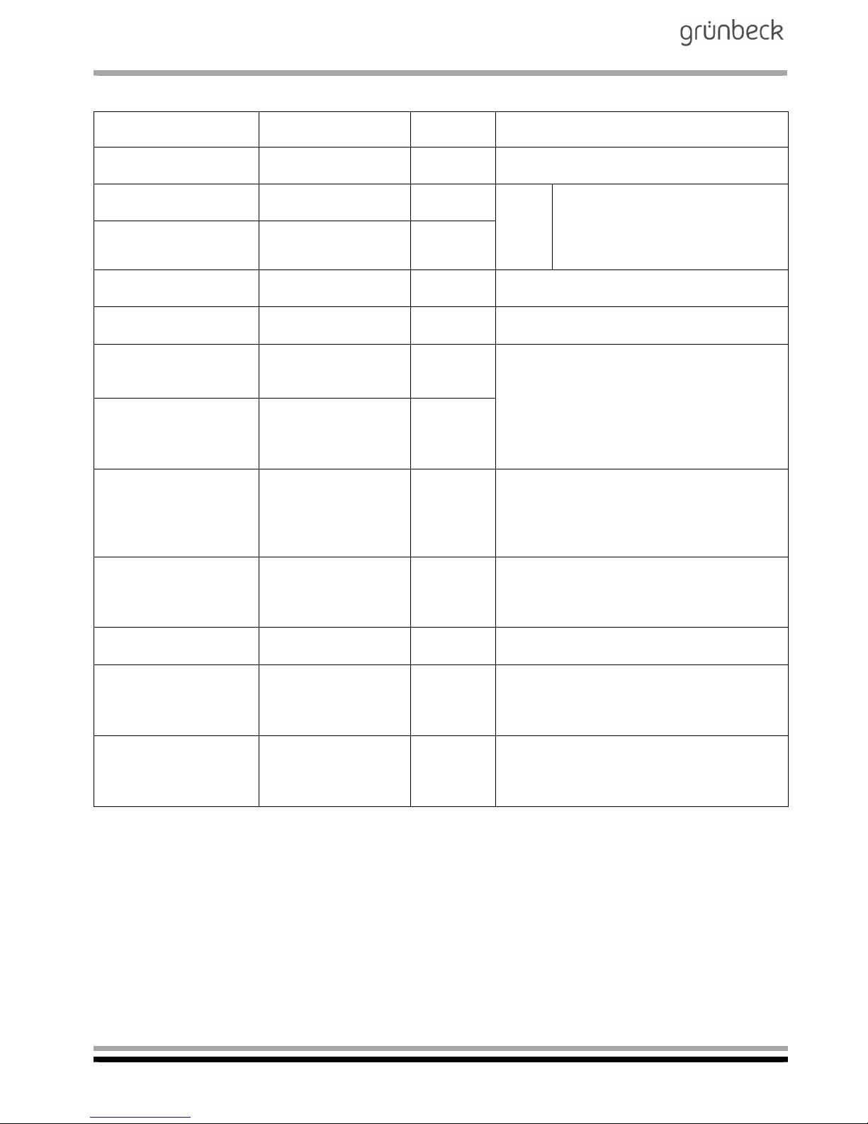
3.3 Reference values / times Code 302
Display / factory
setting
Parameters Setting
range
Comment
1. 2 Operating mode
AVRO-flex 400
Display
only
2,0000 Reference value per-
meate flow [l/h]
0 ... 9999
Note
: The parameters 2. and 3.
must be measured and gauged
while the high-pressure pump is
running.
3,0000 Reference value con-
centrate flow [l/h]
0 ... 9999
6. 5.0 Duration of flushing
[minutes]
0 ... 99.9 Inlet (feed water) and flushing solenoid
valves.
7. 3 System run-down
time [seconds]
1 ... 99 After pressure switch for minimum pressure
responds = operational release.
9. 5 Start-up delay of
high-pressure pump
[seconds]
3 ... 99
After inlet solenoid valve opens.
A. 3 Delay time of pres-
sure switch of highpressure pump
[seconds]
3 ... 99
b. 000 Duration of mainte-
nance interval [days]
0 ... 365 0 = Service interval deactivated.
Acknowledgement of the maintenance
interval (bar above the "screw wrench"
symbol) by reprogramming of the
maintenance interval.
d. 40 Minimum AVRO
treatment current
[mA]
0 .... 200 Treatment current is requested at the end
of the permeate production. In case the
threshold programmed there is undershot,
Er4 is emitted.
E. 3000 AVRO maintenance
interval [h]
0.3000 Acknowledgement of the maintenance
interval by reprogramming the value.
F. 03 Delay time of PS
pump after start of
permeate production
[sec]
1 .... 99 Without function in case of AVRO-flex 300
G. 0.0 Flushing delay after
activation of pressure
switch for operational
release [minutes]
0.0 .... 99.9 Filling mode: If the pressure switch has re-
sponded uninterrupted this long, the system flushes. If the pressure switch drops
out, the permeate production starts.
Page 35
Mobile reverse osmosis system
AVRO-flex 400
Order no. 095 752 946-inter Edited by: phar-mrie G:\BA-752946-INTER_095_AVRO-FLEX_400.DOCX
35
3.4 Error memory / water volumes Code 245
Display Parameters Comment
1.Er_x
...
9.Er_y
Error memory of the 9
most recent errors
1.Er_ = most recent error
9.Er_ = least recent error
▼
A.0372 Operating time [hours]
in workshop mode
Time during which the HP pump is operating in workshop mode.
b.0231 Run time filling mode
[days]
c.0097
d. 00
Run time HP pump
[hours]
Filling mode c = thousands … ones
d = ten thousands
E.0068
F. 00
No function No function
No function
G.0103
H. 00
Permeate volume produced so far [m³]
G = thousands … ones
H = ten thousands
I.0085
L. 00
Concentrate volume
produced so far [m³]
I = thousands … ones
L = ten thousands
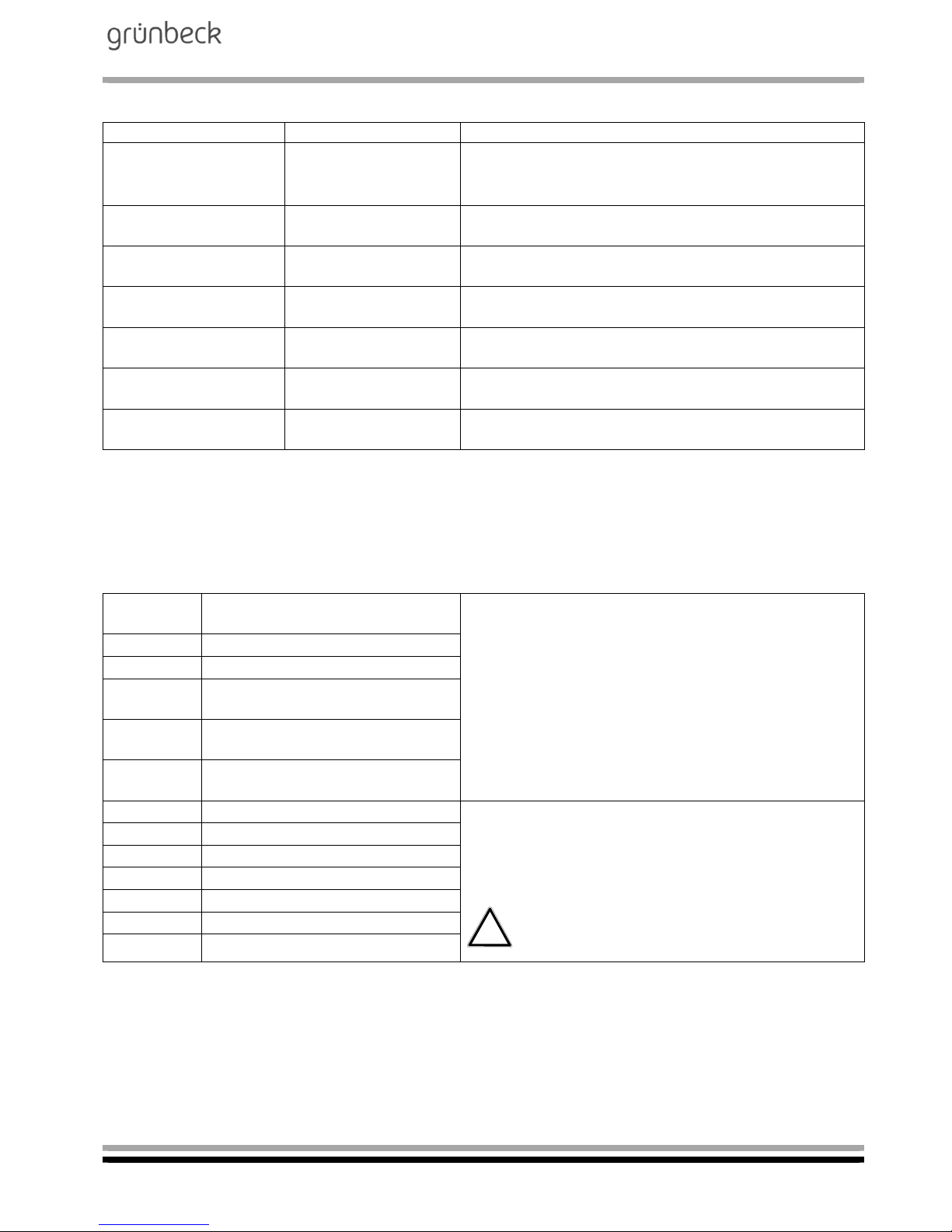
3.5 Diagnosis Code 653
In this code of the customer service programming level, it is possible to
request the states of the inputs and to switch the outputs separately.
Access requirement: System is switched off via ▼ button.
E.PA: Motor protection switch of high-
pressure pump
Physical state of the input signals:
0 = no voltage applied
1 = 24 VDC voltage applied
E.Pb: Switch for workshop mode
E.Pc: Switch for filling mode
E.HP: Pressure switch for minimum pres-
sure of high-pressure pump
E.PS:0 Pressure switch
System ON - Filling mode
E.CL: Input always 1
Motor protection switch PS pump
A.St:0 Voltage-free fault signal contact
Physical state of the output signals:
0 = output switched off
1 = output switched on
Attention! Make sure there is an inflow of water when switching the pumps - risk of running
dry!
A.YE:0 Inlet solenoid valve
A.YS:0 Flushing solenoid valve
A.Yr:0 Reserved
A.HP:0 High-pressure pump
A.PS:0 No function
A.PF:0 Voltage-free signal contact
Page 36
Mobile reverse osmosis system
AVRO-flex 400
Order no. 095 752 946-inter Edited by: phar-mrie G:\BA-752946-INTER_095_AVRO-FLEX_400.DOCX
36
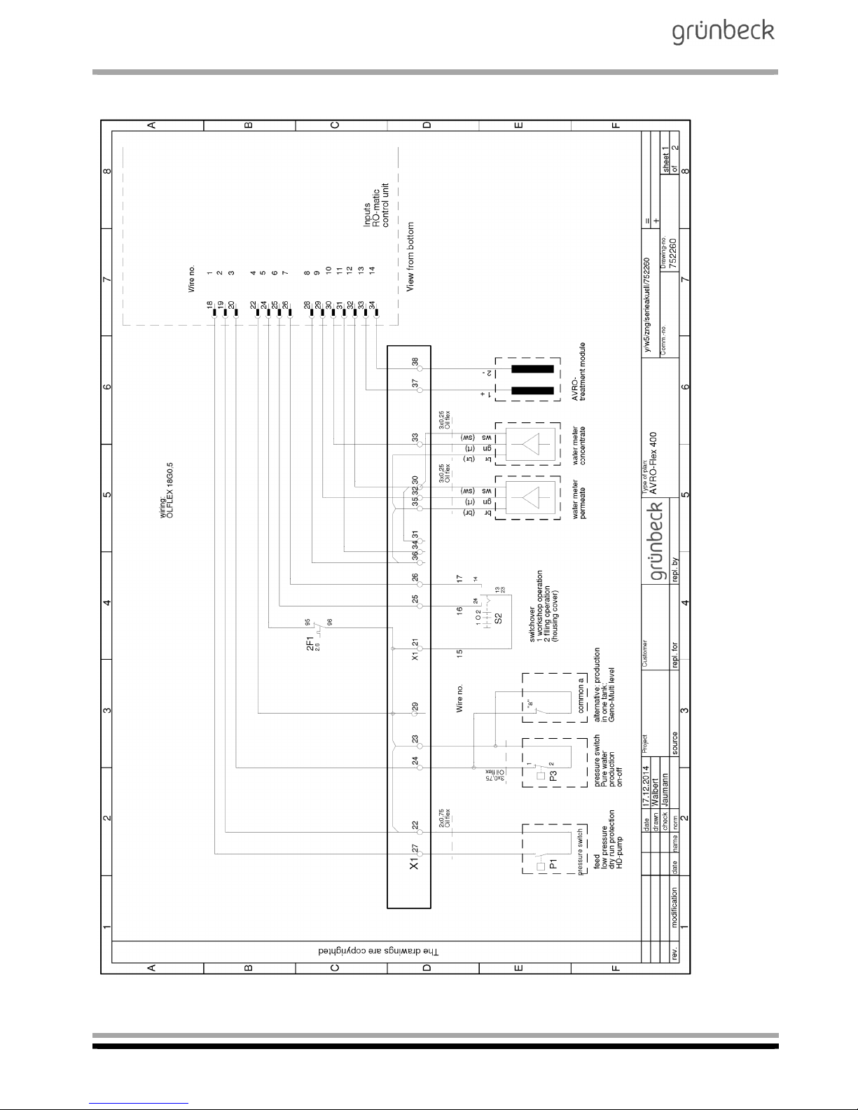
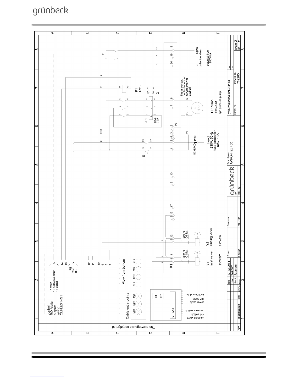
4 | Wiring diagram of mobile reverse osmosis system AVRO-flex 400
Page 37
Mobile reverse osmosis system
AVRO-flex 400
Order no. 095 752 946-inter Edited by: phar-mrie G:\BA-752946-INTER_095_AVRO-FLEX_400.DOCX
37
Page 38
Mobile reverse osmosis system
AVRO-flex 400
Order no. 095 752 946-inter Edited by: phar-mrie G:\BA-752946-INTER_095_AVRO-FLEX_400.DOCX
38
5 | Operation of reverse osmosis system AVRO-flex 400
5.1 How to set the system recovery
A certain part of the feed water must be rejected in order to prevent
the membrane from clogging due to scaling. The ratio of the produced
permeate volume to the feed water volume is called recovery.
5.1.1 How to set the permeate volume
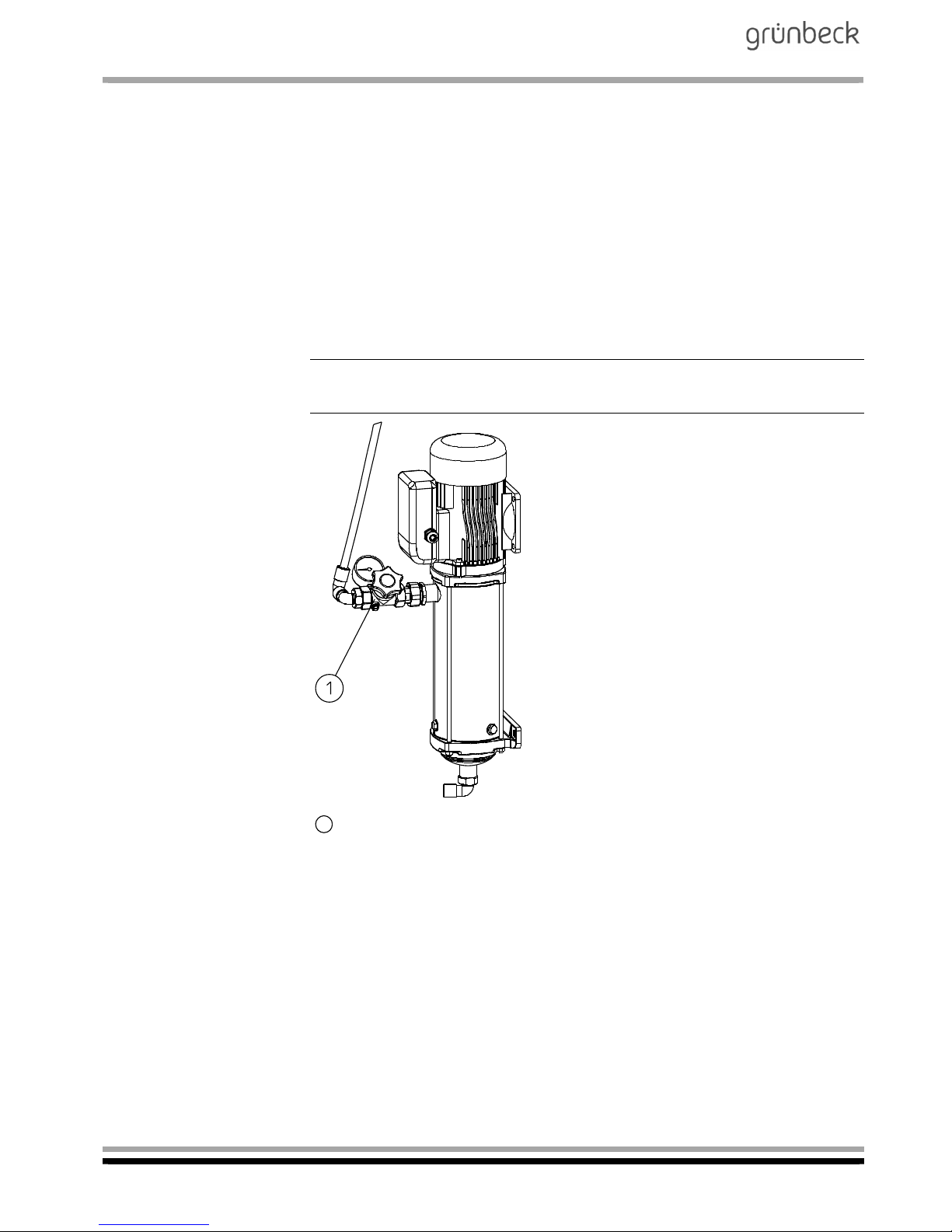
Switch on the system via the ▲ button at the control unit.
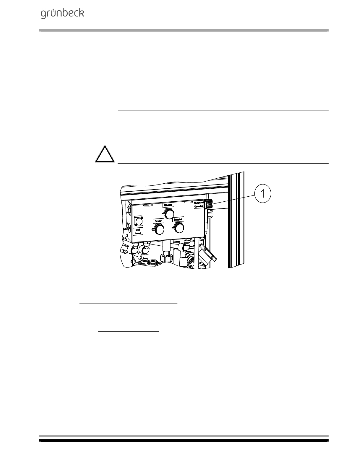
With the control valve for the operating pressure (refer to fig. F-3, item
1), throttle the high-pressure pump in a way that the system-specific
permeate flow of 400 l/h is attained.
Note: The current permeate flow can be displayed via the controller
(refer to Chapter F, paragraph 2.1 “Reading the operating status”).
Control valve for operating pressure
Fig. F-3: Control valve for operating pressure at the high-pressure pump
1
Page 39
Mobile reverse osmosis system
AVRO-flex 400
Order no. 095 752 946-inter Edited by: phar-mrie G:\BA-752946-INTER_095_AVRO-FLEX_400.DOCX
39
5.1.2 How to set the concentrate volume
Set the concentrate flow at the concentrate needle valve (refer to fig.
F-4, item 1).
To safeguard against the valve changing its position, it features a
safety screw which is centrally located at the green cap.
The concentrate flow in a standard system has to be set in a way, that
a recovery of 50 % is attained (400 l/h of permeate flow, 400 l/h of
concentrate flow).
Note: The current concentrate flow and the recovery can be displayed via the controller (refer to Chapter F, paragraph 2.1 “Reading
the operating status”).
Attention! If the set recovery is not met, scaling (precipitation of dissolved salts) occurs on the reverse osmosis membrane.
Fig. F-4: Needle valve, concentrate
Example for the calculation of the recovery
[l/h]flow eConcentrat[l/h]fow Permeate
100%x[l/h]flow Permeate
[%]Recovery
[l/h]flow Permeate
[%]recovery eConcentrat
100x[l/h]flow Permeate
[l/h]flow eConcentrat
Page 40
Mobile reverse osmosis system
AVRO-flex 400
Order no. 095 752 946-inter Edited by: phar-mrie G:\BA-752946-INTER_095_AVRO-FLEX_400.DOCX
40
G Troubleshooting
Even carefully designed and manufactured technical systems that are
operated properly, may experience malfunctions. Table G-1 provides
an overview of possible problems that may occur during the operation
of the systems and indicates the causes and their elimination.
The systems are equipped with an error detection and reporting system. If an error message is displayed:
1. Press P button (= acknowledge malfunction).
2. Watch the display.
If the message reappears, compare it with table G-1.
3. If necessary, notify Grünbeck’s technical service.
Note: The technical service definitely must be notified (refer to
gruenbeck.de) in case of malfunctions that cannot be remedied with
the information given in table G-1! When contacting the technical service, please indicate the system designation, serial number and the
error message displayed.
Table G-1: Troubleshooting
This is what you observe This is the cause This is what to do
Water quality deteriorated
by 50 %.
Membrane clogged. Replace or flush the membrane1).
Feed water values deteriorated. Check feed water values.
Solenoid valve does not
open.
Coil defective or fuse F1 blown
on circuit board.
Replace coil or fuse T1A.
Solenoid valve does not
close.
Valve contaminated. Clean valve.
Bar appears in the display above Symbol
Close.
High-pressure pump:
Thermostat contact has responded, pump has overheated.
Upstream hardness monitor-
ing or water treatment locks
the system.
Wait until the pump has cooled
down again, the system will
then automatically continue to
produce.
Inspect system installed up-
stream.
Bar appears in the display above screw wrench
symbol (without further indications of a malfunction).
Service interval has elapsed. Have maintenance performed.
Page 41
Mobile reverse osmosis system
AVRO-flex 400
Order no. 095 752 946-inter Edited by: phar-mrie G:\BA-752946-INTER_095_AVRO-FLEX_400.DOCX
41
Continuation Table G-1: Troubleshooting
This is what you observe This is the cause This is what to do
Er 0 Power failure > 5 minutes
Refer to Chapter F / paragraph
3.2 / parameter A:
Depending on the setting, the
system either continues to run or
remains switched off.
Check power supply for failures.
Er 1 Pressure drop at pressure switch
for minimum pressure of highpressure pump:
Refer to Chapter F / paragraph
3.1 / parameter EHP:
Depending on the setting, the
system has previously undertaken 6 unsuccessful start attempts.
Restore primary pressure of feed
water.
Er 4 Minimum AVRO treatment cur-
rent undershot.
Have the AVRO treatment module
replaced immediately by
Grünbeck’s technical service/authorised service company. The
malfunction can be acknowledged
once and a maximum of 5 m³ of
permeate can still be produced.
Er 5 System recovery too high:
Recovery was above 60 % for
more than 1 h
Gauge and reset the system.
Er 6 AVRO maintenance interval has
elapsed.
Notify Grünbeck’s technical service/authorised service company
to have the AVRO treatment module replaced promptly.
Er 7 No function
Er 8 Motor protection switch of high-
pressure pump has responded.
Notify Grünbeck’s technical service/authorised service company
to have the high-pressure pump
checked and replaced, if necessary
Er 9 In workshop mode, a shut-off
valve is closed on the permeate
side.
Open shut-off valve and
acknowledge malfunction.
1)
Separate flushing instructions for membranes are available for authorised service personnel, order no. 700 950.
Page 42
Mobile reverse osmosis system
AVRO-flex 400
Order no. 095 752 946-inter Edited by: phar-mrie G:\BA-752946-INTER_095_AVRO-FLEX_400.DOCX
42
H Maintenance and care
1 | Basic information
In order to guarantee the reliable function of the systems over a long
period of time, some maintenance work has to be performed at regular intervals. All regulations and guidelines which apply at the installation site must be strictly adhered to.
Check the quality and the system volume flows every day.
Maintenance has to be performed by Grünbeck’s technical ser-
vice/authorised service company or by a specialised company.
Maintenance is subject to the load but at the latest has to be performed once a year.
An operation log and the corresponding test log must be kept in or-
der to document the maintenance work performed.
Note: By concluding a maintenance contract you ensure that all
maintenance work will be performed in due time.
The maintenance work performed must be documented in the checklist, refer to appendix "Operation log".
2 | Inspection (functional check)
You may perform the daily inspections yourself.
Please refer to the following summary for the tasks to be performed
within the framework of an inspection.
Summary: Inspection work
Read the recovery
Note: Minor deviations are normal and cannot be prevented technically. In case of considerable deviations from the standard, notify
Grünbeck's technical service.
Take the remaining time of the AVRO treatment unit’s maintenance
interval into consideration (refer to Chapter F, paragraph 2.1). If the
remaining time is < 100 hours, notify Grünbeck’s technical service/
authorised service company to have the treatment module replaced.
Take the remaining time of the maintenance interval [d] into consid-
eration (refer to Chapter F - paragraph 2.1 “Reading the operating
state”). In case the remaining time of the maintenance interval is <
30 days, inform Grünbeck's technical service about the impending
service.
Page 43
Mobile reverse osmosis system
AVRO-flex 400
Order no. 095 752 946-inter Edited by: phar-mrie G:\BA-752946-INTER_095_AVRO-FLEX_400.DOCX
43
Check the system’s tightness to the drain. Solenoid valves are not
tightened, visible in the display (refer to fig. F-2, items 9 and 10). In
this state, no water must creep to the drain.
Note: Leaky solenoid valves will cause the system to consume more
water. The recovery will be reduced.
3 | Maintenance
According to DIN 1988 part 8 / A 12, maintenance work at the systems may only be performed by Grünbeck’s technical service/authorised service company or an approved specialist company.
For this kind of systems, an operation log - a checklist has to be kept.
In this operation log, the customer service technician records all
maintenance and repair work performed. In case of malfunctions, this
log helps to identify possible sources of error. In addition, the log documents the proper system maintenance.
Note: Make sure that all maintenance work is recorded in the operation log as well as in the corresponding test log.
Summary: Maintenance work
Replace the filter element.
If necessary, replace the filter element of the activated carbon filter.
Check the permeate quality; flush or replace the membrane, if nec-
essary. So-called flushing instructions (order no. 700 950) are available for authorised service personnel.
Replacement of AVRO treatment unit, if necessary
(limit value: 3000 h or 5 years)
Solenoid valves – check function, clean if necessary.
Check the flow volumes and recalibrate the water meters.
Check the state of the entire system and check the entire system
for tightness.
Mechanical resp. electrical functional and performance check of all
aggregates (pumps, valves).
Prepare a written maintenance log on the state and function of the
system and the maintenance work performed, incl. evaluation and
assessment of the operating values and water analysis results.
Note: The maintenance work performed must be documented in the
checklist, refer to appendix "Operation log".
Page 44

Mobile reverse osmosis system
AVRO-flex 400
Order no. 095 752 946-inter Edited by: phar-mrie G:\BA-752946-INTER_095_AVRO-FLEX_400.DOCX
44
3.1 Operation log
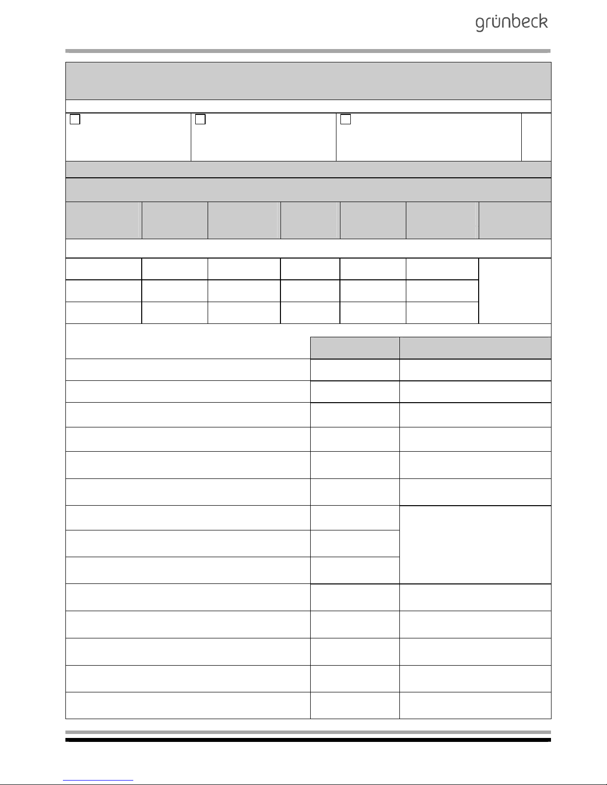
The operation log is located in Chapter H, paragraph 4 of this operation manual. When starting up the system, make sure to record all
data on the cover sheet of the operation log and fill in the first column
of the checklist.
The customer service technician will fill in a column of the check list
whenever maintenance is performed. This document provides evidence of proper maintenance.
Page 45

Mobile reverse osmosis system
AVRO-flex 400
Order no. 095 752 946-inter Edited by: phar-mrie G:\BA-752946-INTER_095_AVRO-FLEX_400.DOCX
45
4 | Operation log
Customer
Name: .......................................................................................
Address: ...................................................................................
.................................................................................................
.................................................................................................
Mobile reverse osmosis system AVRO-flex 400
Order no. 752 250
Serial number
.................................................................................
Page 46
Mobile reverse osmosis system
AVRO-flex 400
Order no. 095 752 946-inter Edited by: phar-mrie G:\BA-752946-INTER_095_AVRO-FLEX_400.DOCX
46
Maintenance work on mobile reverse osmosis system AVRO-flex 400
Checklist
Please enter measured values. Confirm checks with OK or enter repair work performed.
Maintenance performed
without replacement of
module
Maintenance performed
with replacement of module
Maintenance performed with replace-
ment of AVRO treatment module
Module no. ..........................
Treatment module no. …………………..
Measured values
Water volumes and water qualities before the replacement of the module / after the replacement of the
module or in case of maintenance
Pump pressure
[bar]
before/after
Conductivity
[S/cm]
before/after
Total hardness
[dH]
before/after
Carbonate
hardness:
[KH]
Temperature
[C]
Volume flow
[l/h]
Recovery
[%]
before/after before/after before/after
/
Feed water
/ / / /
Permeate
/ / / /
Concentrate
/ / / /
. . . . . % / . . . . %
Confirmation Remarks
Water meter reading upstream of the system [m³]
Inlet water pressure (2.5 - 4 bar) checked
Filter elements replaced
(incl. activated carbon)
Settings of electronics checked
Water meter configured
(code 302, par. 2 + 3)
[l/h]
Run time in workshop mode
(code 290, par. d)
[min.]
AVRO treatment current (Chapter F, 2.1) [mA]
Operating period in workshop mode
(code 245, par. A)
[h]
Run time in filling mode
(code 245, par. b)
[T]
Run time of high-pressure pump
(code 245, par. c/d)
[h]
No function
(code 245, par. E/F)
[h]
Permeate volume produced
(code 245, par. G/H)
[m³]
Concentrate volume generated
(Code 245, par. I/L)
[m³]
Error memory
(code 245, par. 1..9)
[Er]
Page 47
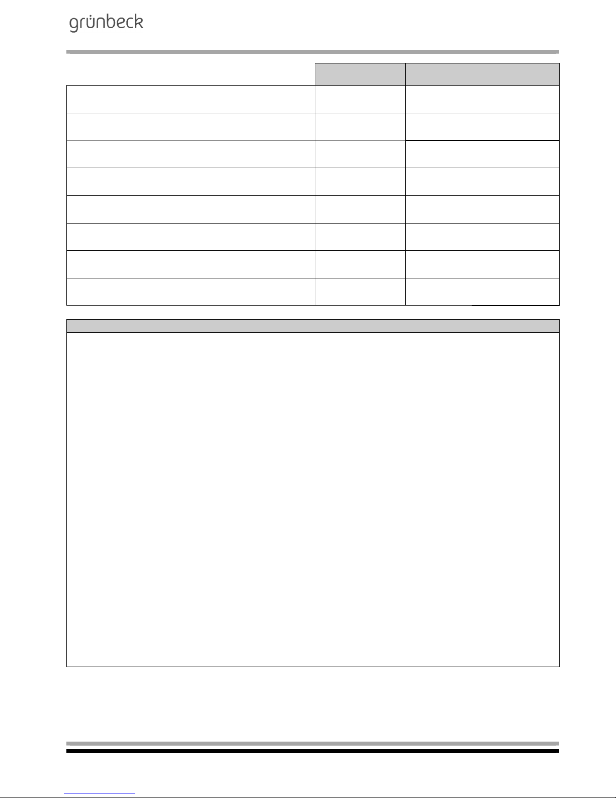
Mobile reverse osmosis system
AVRO-flex 400
Order no. 095 752 946-inter Edited by: phar-mrie G:\BA-752946-INTER_095_AVRO-FLEX_400.DOCX
47
Confirmation Remarks
All electrical lines checked for external
damage
All hoses and connections checked for
external damage
Inlet solenoid valve checked for tightness cleaned, if necessary
Pressure switch of high-pressure pump
checked for function
Pressure switch - switching hysteresis
Pressure booster checked/adjusted
Visual check of the control unit
System checked for tightness
Miscellaneous
Remarks: ........................................................................................................................................................
.......................................................................................................................................................................
.......................................................................................................................................................................
.......................................................................................................................................................................
.......................................................................................................................................................................
.......................................................................................................................................................................
Start-up technician / CS technician: .............................................
Company: ....................................................................................
.....................................................................................................
.....................................................................................................
Work time certificate (no.) ............................................................
Date/signature ..............................................................................
Page 48
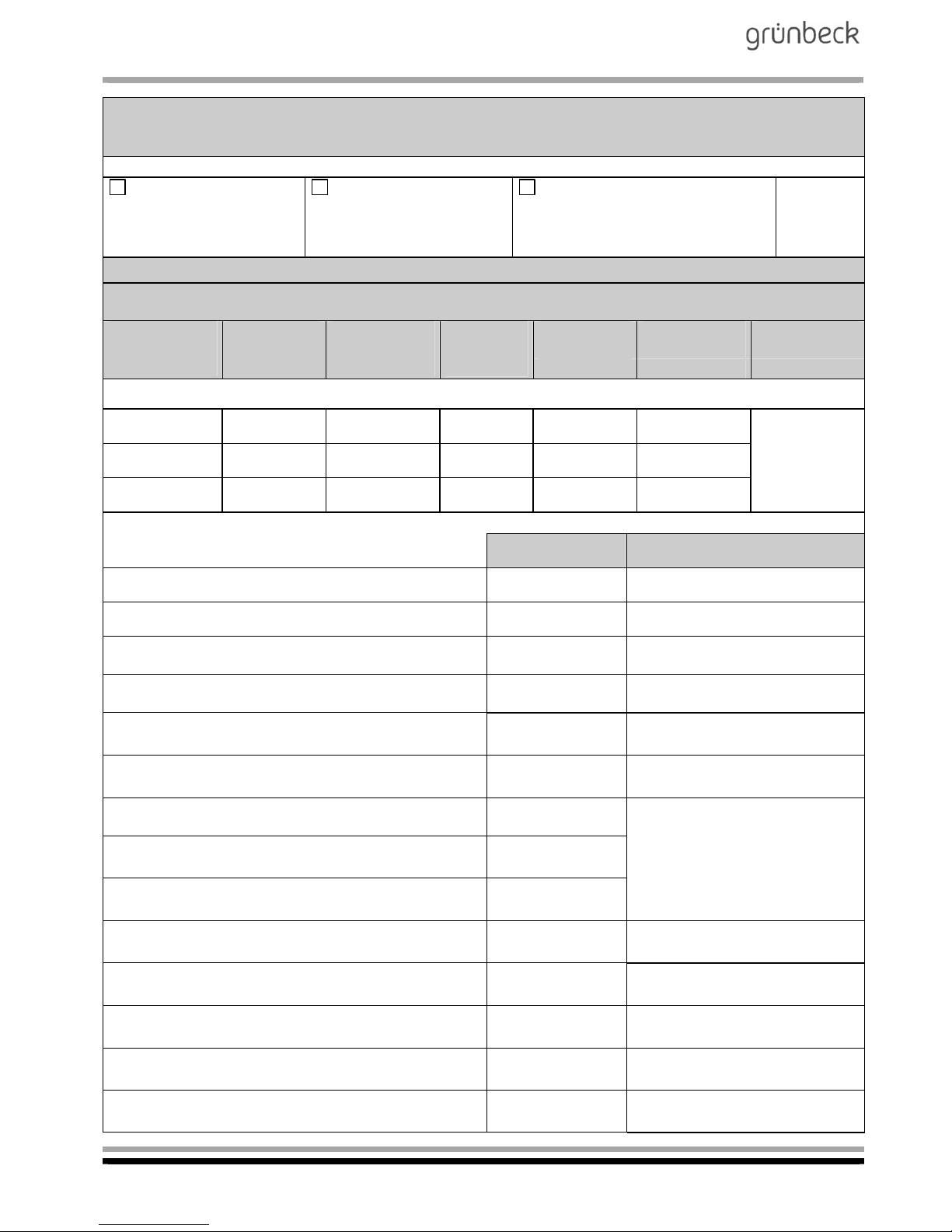
Mobile reverse osmosis system
AVRO-flex 400
Order no. 095 752 946-inter Edited by: phar-mrie G:\BA-752946-INTER_095_AVRO-FLEX_400.DOCX
48
Maintenance work on mobile reverse osmosis system AVRO-flex 400
Checklist
Please enter measured values. Confirm checks with OK or enter repair work performed.
Maintenance performed
without replacement of
module
Maintenance performed
with replacement of
module
Maintenance performed with re-
placement of AVRO treatment
module
Module no. .......................... Treatment module no. ………………
Measured values
Water volumes and water qualities before the replacement of the module / after the replacement of the
module or in case of maintenance
Pump pressure
[bar]
before/after
Conductivity
[S/cm]
before/after
Total hardness
[dH]
before/after
Carbonate
hardness:
[KH]
Temperature
[C]
Volume flow
[l/h]
Recovery
[%]
before/after before/after before/after
/
Feed water
/ / / /
Permeate
/ / / /
Concentrate
/ / / /
. . . . . % / . . . . %
Confirmation Remarks
Water meter reading upstream of the system [m³]
Inlet water pressure (2.5 - 4 bar) checked
Filter elements replaced
(including activated carbon)
Settings of electronics checked
Water meter configured
(code 302, par. 2 + 3)
[l/h]
Run time in workshop mode
(code 290, par. d)
[min.]
AVRO treatment current (Chapter F, 2.1) [mA]
Operating period in workshop mode
(code 245, par. A)
[h]
Run time in filling mode
(code 245, par. b)
[T]
Run time of high-pressure pump
(code 245, par. c/d)
[h]
No function
(code 245, par. E/F)
[h]
Permeate volume produced
(code 245, par. G/H)
[m³]
Concentrate volume generated
(Code 245, par. I/L)
[m³]
Error memory
(code 245, par. 1..9)
[Er]
Page 49
Mobile reverse osmosis system
AVRO-flex 400
Order no. 095 752 946-inter Edited by: phar-mrie G:\BA-752946-INTER_095_AVRO-FLEX_400.DOCX
49
Confirmation Remarks
All electrical lines checked for external
damage
All hoses and connections checked for
external damage
Inlet solenoid valve checked for tightness cleaned, if necessary
Pressure switch of high-pressure pump
checked for function
Pressure switch - switching hysteresis
Pressure booster checked/adjusted
Visual check of the control unit
System checked for tightness
Miscellaneous
Remarks: ........................................................................................................................................................
.......................................................................................................................................................................
.......................................................................................................................................................................
.......................................................................................................................................................................
.......................................................................................................................................................................
.......................................................................................................................................................................
Start-up technician / CS technician: .............................................
Company: ....................................................................................
.....................................................................................................
.....................................................................................................
Work time certificate (no.) ............................................................
Date/signature ..............................................................................
Page 50
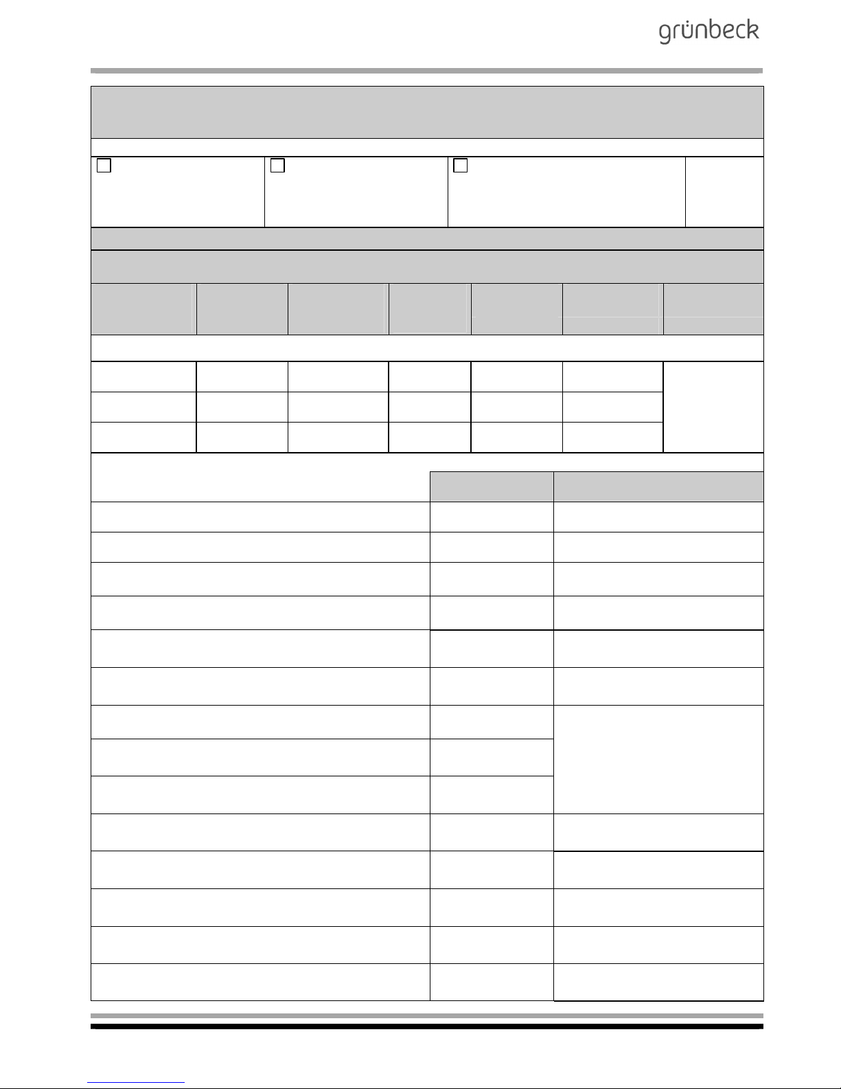
Mobile reverse osmosis system
AVRO-flex 400
Order no. 095 752 946-inter Edited by: phar-mrie G:\BA-752946-INTER_095_AVRO-FLEX_400.DOCX
50
Maintenance work on mobile reverse osmosis system AVRO-flex 400
Checklist
Please enter measured values. Confirm checks with OK or enter repair work performed.
Maintenance performed
without replacement of
module
Maintenance performed
with replacement of
module
Maintenance performed with re-
placement of AVRO treatment
module
Module no. .......................... Treatment module no. ……………….
Measured values
Water volumes and water qualities before the replacement of the module / after the replacement of the
module or in case of maintenance
Pump pressure
[bar]
before/after
Conductivity
[S/cm]
before/after
Total hardness
[dH]
before/after
Carbonate
hardness:
[KH]
Temperature
[C]
Volume flow
[l/h]
Recovery
[%]
before/after before/after before/after
/
Feed water
/ / / /
Permeate
/ / / /
Concentrate
/ / / /
. . . . . % / . . . . %
Confirmation Remarks
Water meter reading upstream of the system [m³]
Inlet water pressure (2.5 - 4 bar) checked
Filter elements replaced
(including activated carbon)
Settings of electronics checked
Water meter configured
(code 302, par. 2 + 3)
[l/h]
Run time in workshop mode
(code 290, par. d)
[min.]
AVRO treatment current (Chapter F, 2.1) [mA]
Operating period in workshop mode
(code 245, par. A)
[h]
Run time in filling mode
(code 245, par. b)
[T]
Run time of high-pressure pump
(code 245, par. c/d)
[h]
No function
(code 245, par. E/F)
[h]
Permeate volume produced
(code 245, par. G/H)
[m³]
Concentrate volume generated
(Code 245, par. I/L)
[m³]
Error memory
(code 245, par. 1..9)
[Er]
Page 51
Mobile reverse osmosis system
AVRO-flex 400
Order no. 095 752 946-inter Edited by: phar-mrie G:\BA-752946-INTER_095_AVRO-FLEX_400.DOCX
51
Confirmation Remarks
All electrical lines checked for external
damage
All hoses and connections checked for
external damage
Inlet solenoid valve checked for tightness cleaned, if necessary
Pressure switch of high-pressure pump
checked for function
Pressure switch - switching hysteresis
Pressure booster checked/adjusted
Visual check of the control unit
System checked for tightness
Miscellaneous
Remarks: ........................................................................................................................................................
.......................................................................................................................................................................
.......................................................................................................................................................................
.......................................................................................................................................................................
.......................................................................................................................................................................
.......................................................................................................................................................................
Start-up technician / CS technician: .............................................
Company: ....................................................................................
.....................................................................................................
.....................................................................................................
Work time certificate (no.) ............................................................
Date/signature ..............................................................................
 Loading...