

Grunaire GMU018HXB-2, GMU024HXB-2, GMU028HXB-3, GMU028HXB-4 Service Manual

Service Manual
MODEL: GMU018HXB-2
GMU024HXB-2
GMU028HXB-3
GMU028HXB-4
(Refrigerant R410A)

Table of Contents
Summary and features..................................................................................1
Part 1 Safety Precautions
..........................................................................................2
Part 2 Specifications.....................................................................................................3
Part 3 Construction Views
........................................................................................7
Part 4 Refrigerant System Diagram
.....................................................................9
5.1 Electrical Data......................................................................................................10
5.2 Electrical Wiring....................................................................................................10
5.3 Printed Circuit Board.............................................................................................13
Part 5 Schematic Diagram......................................................................................10
6.1 Models GMU018HXB-2,GMU024HXB-2..............................................................20
6.2 Models GMU028HXB-3,GMU028HXB-4..............................................................24
Part 6 Description of Each Control Operation
............................................20
Part 7 Installation Manual
........................................................................................29
7.1 Installing the Outdoor Unit....................................................................................29
7.2 Bleeding...............................................................................................................29
7.3 Installation Dimension Diagram...........................................................................30
7.4 Check After Installation........................................................................................31
Part 8 Exploded Views and Parts List
..............................................................32
Part 9 Troubleshooting...............................................................................................40
9.1 ......................................................................................................40
9.2 ...............................................................................................40
9.3 .................................................................................................46
8.1 GMU018HXB-2.....................................................................................................32
8.2 GMU024HXB-2.....................................................................................................34
8.3 GMU028HXB-3 GMU028HXB-4...........................................................................37
Part10 Removal Procedure.......................................................................................54
10.1
Model:GMU018HXB-2
........................................................................................54
10.2
Model:GMU024HXB-2
.........................................................................................58
10.3
Model:GMU028HXB-3 GMU028HXB-4
...............................................................62
Common Parts
Malfunction Display
Troubleshooting
...
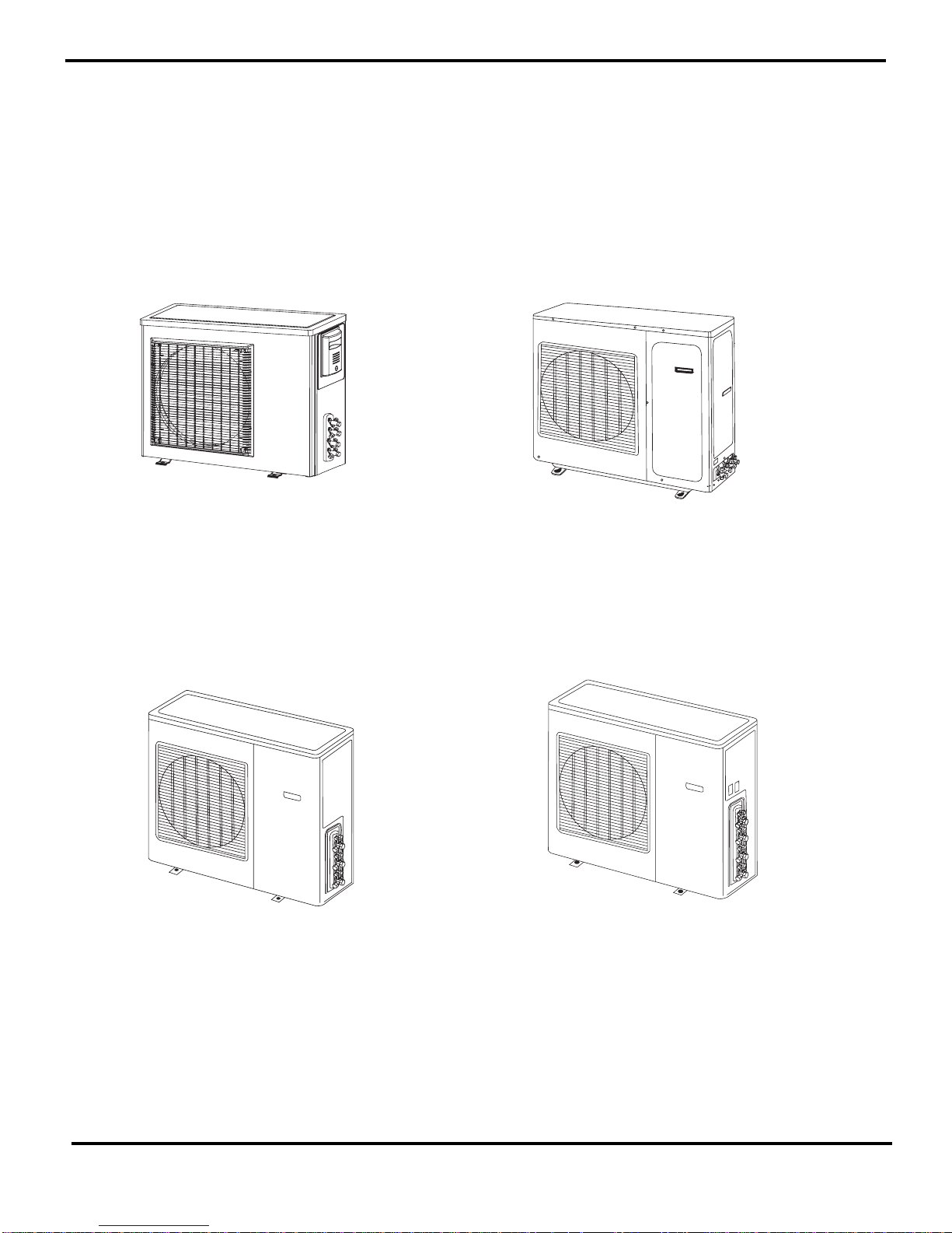
Summary and features
1
Model:
GMU018HXB-2
GMU028HXB-3
GMU024HXB-2
GMU028HXB-4
Summary and features
2
1.Safety Precautions
Safety Precautions
Caution
Warning
Warning
Caution
could result in
personal injury
or death.
Incorrect handling
result in
injury, or damage to product
or property.
Incorrect handling
may
minor
Recognize the following safety information:
Installing, starting up, and servicing air conditioner can be
hazardous due to system pressure, electrical components, and
equipment location, etc.
Only trained, qualified installers and service personnel are
allowed to install, start-up, and service this equipment.
Untrained personnel can perform basic maintenance functio ns
such as cleaning coils. All other operations should be
performed by trained service personnel.
When handling the equipment, observe precautions in the
manual and on tags, stickers, and labels attached to the
equipment. Follow all safety codes. Wear safety glasses and
work gloves. Keep quenching cloth and fire extinguisher nearby
when brazing.
Read the instructions thoroughly and follow all warnings or
cautions in literature and attached to the unit. Consult local
building codes and current editions of national as w ell as local
electrical codes.
All electric work must be performed by a licensed technician
according to local regulations and the instruct ions gi ven in this
manual.
Never supply power to the unit unless all wiring and tubi ng
are completed, reconnected and checked.
This system adopts highly dangerous electrical voltage.
Incorrect connection or inadequate grounding can cause
personal injury or death. Stick to the wiring diagram and all
the instructions when wiring.
Have the unit adequately grounded in accordance with
local electrical codes.
Have all wiring connected tightly. Loose connection may
lead to overheating and a possible fire hazard.
All installation or repair work shall be performed by your dealer
or a specialized subcontractor as there is the risk of fire, electric
shock, explosion or injury.
Make sure the ceiling/wall is strong enough to bear the
weight of the unit.
Make sure the noise of the outdoor unit does not disturb
neighbors.
Properly insulate any tubing running inside the room to
prevent the water from damaging the wall.
Make sure the outdoor unit is installed on a stable, level
surface with no accumulation of snow, leaves, or trash
beside.
Follow all the installation instructions to minimize the risk
of damage from earthquakes, typhoons or strong winds.
Avoid contact between refrigerant and fire as it generates
poisonous gas.
Apply specified refrigerant only. Never have it mixed with
any other refrigerant. Never have air remain in the
refrigerant line as it may lead to rupture and other hazards.
Make sure no refrigerant gas is leaking out when
installation is completed.
Should there be refrigerant leakage, the density of
refrigerant in the air shall in no way exceed its limited
value, or it may lead to explosion.
Before installing, modifying, or servicing system, main
electrical disconnect switch must be in the OFF position.
There may be more than 1 disconnect switch. Lock out and
tag switch with a suitable warning label.
Keep your fingers and clothing away from any moving
parts.
Clear the site after installation. Make sure no foreign
objects are left in the unit.
Always ensure effective grounding for the unit.
Never install the unit in a place where a combustible gas
might leak, or it may lead to fire or explosion.
Make a proper provision against noise when the unit is
installed at a telecommunication center or hospital.
Provide an electric leak breaker when it is installed in a
watery place.
Never wash the unit with water.
Handle unit transportation with care. The unit should not be
carried by only one person if it is more than 20kg.
Never touch the heat exchanger fins with bear hands.
Never touch the compressor or refrigerant piping withou t
wearing glove.
Do not have the unit operate without air filter.
Should any emergency occur, stop the unit and disconnect
the power immediately.

3
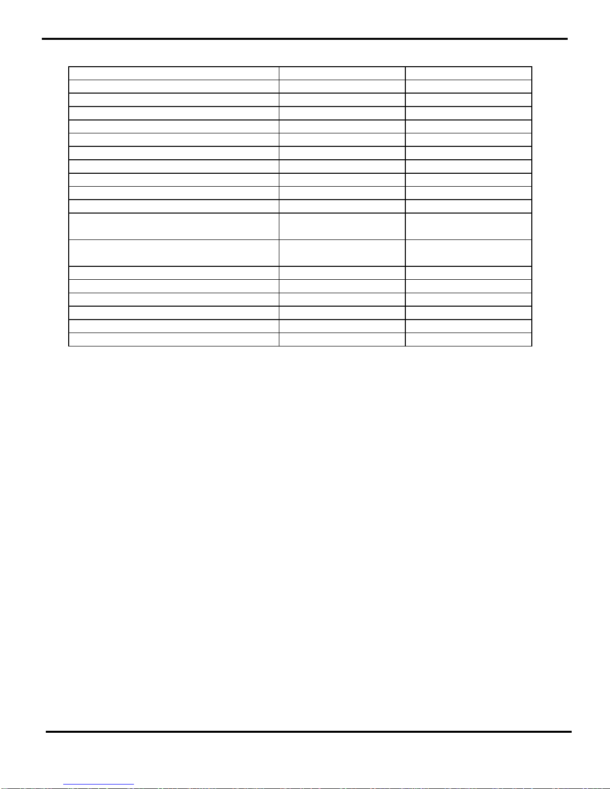
Specifications
2.Specifications
GMU018HXB-2 GMU024HXB-2
(
1 to 2
)(
1 to 2
)
CB228W0030_ K27204 CB228W0040_ K27204
R410A R410A
Cooling capa c ity Max 21 28
(KBTU) Nom 18 24
Min 7.2 10
Max 2300 3300
Nom 1550 2250
Min 620 1100
16 16
Heatin g c apa c ity Max 22 33
(KBTU) Nom 19 29.5
Min 6.5 9
Max 2400 3500
Nom 1750 2600
Min 650 1250
56 59
52/57 68/73
Liquid connections Diameter mm Φ6 Φ6
Gas connec tions Diameter mm Φ9.52 Φ12
Shenyang SANYO Shenyang SANYO
C-6RVN93HOV C-7RZ233H1A
Rotary Rotary
41 34
8.96 8.2
1470 1760
1NT11L-3979 1NT11L-3979
Elec tronic E xpansion Valve Electronic Ex pa nsion Valve
Tr ansducer starting Transducer starting
-7≤T≤43 -7≤T≤43
Aluminum fin-copper tube Aluminum fin-coppe r tube
Φ7 Φ9.52
2-1.4 2-1.4
806X660X22 683X813X44
Outdoor unit Model
Product Code
Power supply 1PH 208- 230V~ 60Hz
Refrigerant
Total power input in cooling mode (W)
SEER
Total power input in heat ing mode
Sound pr essure level In door un it
outd oor Ne t Weight /Gross Weight ( k g )
Compressor Manuf ac t ur er /tr ademark
Compressor Model
Compressor T ype
L.R.A. (A)
Compressor RLA(A)
Compressor Pow er Input( W )
Over load P r ot ec t o r
Thr ottlin g Method
St arting Method
Wor k i ng Temp Range (℃)
Condenser
Pipe Diameter (mm)
Rows-Fin Gap(mm)
Coil lengt h (l) X height (H) X coil width (L)
Specifications
4
The above data is subject to change without notice. Please refer to the nameplate of the unit.
780/-/600 780/-/600
60 60
0.65 0.65
33
//
Ax ial fan Axial f an
460 460
Auto defrost Auto defrost
T1 T1
II
IP24 IP24
3.8 3.8
1.2 1.2
56/54 59/58
66/64 69/68
913X680X378 950X840X412
994X428X750 1100X450X905
52/57 68/73
1.6 2.5
Fan Motor Spee d ( r p m) (H/M/L)
Output of Fan Mot o r (W)
Fan Mot or RLA( A)
Fan Motor Capac itor (μF)
Air F low Volume of Outdoo r U nit
Fan Type
Fan Di ameter (mm)
Defrosting Method
Climate T ype
Isolation
Moist ur e Protection
Permissib le E xc essiv e Operating Pressure for the
Discharge Side ( MP a)
Dimension of Pack a ge (L/W /H)( mm)
Net Weight /Gro ss Weight ( k g)
Refrigerant Charge (kg)
Permissib le E xc essiv e Operating Pressure for the
Suction Side(M Pa)
Sound Pressure Level dB (A) (H/L)
Sound P ower Level dB ( A) ( H/L)
Dimension ( W/H/D) ( mm)
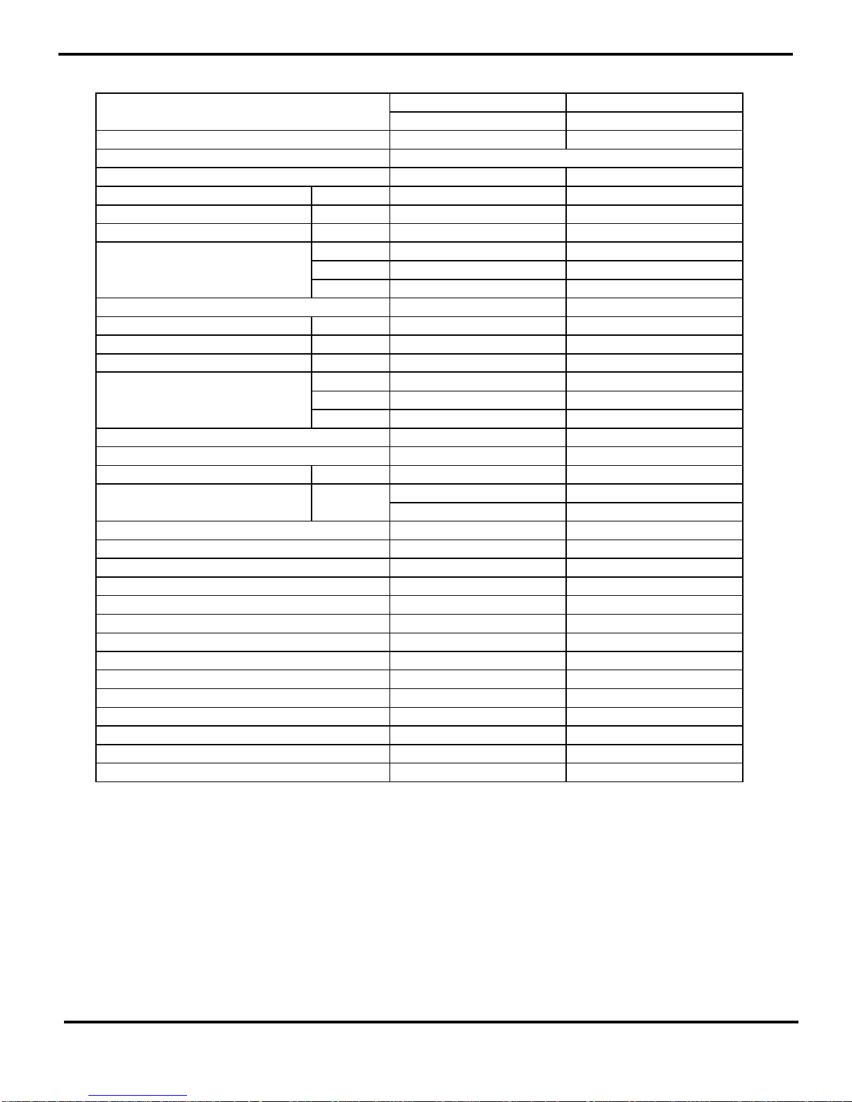
5
Specifications
GMU028HXB-3 GMU028HXB-4
(
2 to 3
)(
2to 4
)
CB228W 00 50_ K27 204 CB228W 00 60_ K272 04
R410A R410A
Cooling capa c ity Max 34 34
(KBTU) Nom 28 28
Min 10 10
Max 4700 4700
Nom 2600 2600
Min 900 900
16 16
Heatin g c apa c i ty Max 37 37
(KBTU) Nom 31 31
Min 9 9
Max 3000 3000
Nom 2500 2500
Min 800 800
60 60
75/80 75/80
Liquid connec tions Diameter mm Φ6 Φ6
Φ9.52 Φ9.52
Φ12 Φ12
Shenyang SANYO Shenyang S ANYO
C-7RZ233H1A C-7RZ233H1A
Rotary Rotary
34 34
8.2 8.2
1760 1760
1NT11L-3979 1NT11L-3979
Electronic Ex pa nsion Valve Electronic Ex pan sion Valve
Tr ansducer st ar ting Transducer st ar t ing
-7≤T≤43 -7≤T≤43
Aluminum fin-coppe r tube Al uminum fin-c o pper tube
Φ9.52 Φ9.52
2-1.4 2-1.4
806X813X44 806X813X44
Outdoor unit Model
Product Code
Power supply 1PH 208-230V~ 60Hz
Refrigerant
Total power input in cooling mode (W)
SEER
Total power input in heat in g mode
Sound pr essure level I ndoor u nit
outd oor N et Weight /Gross Weight ( kg)
Gas connec tions Diameter mm
Compressor Manuf ac turer/tr ademark
Compressor Model
Compressor T ype
L.R.A. (A)
Compressor RLA(A)
Compressor Pow er Input( W)
Over load P r ot ec tor
Thr ottlin g Method
Rows-Fin Gap(mm)
Coil lengt h (l) X height (H) X coil width (L)
St arting Method
Wor k ing T emp Range (℃)
Condenser
Pipe Diameter ( mm)

Specifications
6
The above data is subject to change without notice. Please refer to the nameplate of the unit.
840/740/640 840/740/640
68 68
0.68 0.68
33
//
Ax ial fan Axial f an
460 460
Auto defrost Auto defrost
T1 T1
II
IP24 IP24
3.8 3.8
1.2 1.2
60/54 60/54
70/64 70/64
950X840X412 950X840X412
1100X450X905 1100X450X905
75/80 75/80
3.3 3.3
Dimension of Pack a ge (L/W /H)( mm)
Net Weight /Gro ss Weight ( k g)
Refrigerant Charge (kg)
Permissib le E xc essiv e Operating Pressure for the
Suction Side(M Pa)
Sound Pressure Level dB (A) (H/L)
Sound P ower Level dB ( A) ( H/L)
Dimension ( W/H/D) ( mm)
Climate T ype
Isolation
Moist ur e Protection
Permissib le E xc essiv e Operating Pressure for the
Discharge Side ( MP a)
Air F low Volume of Outdoo r U nit
Fan Type
Fan Di ameter (mm)
Defrosting Method
Fan Motor Spee d ( r p m) (H/M/L)
Output of Fan Mot o r (W)
Fan Mot or RLA( A)
Fan Motor Capac itor (μF)
7
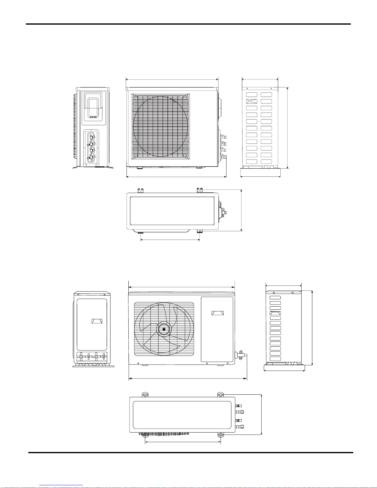
Constrction views
3. Construction Views
Model GMU018HXB-2
550
680
342
846
300
913
572
340
840
378
950
1018
Unit:mm
GMU024HXB-2
412
378
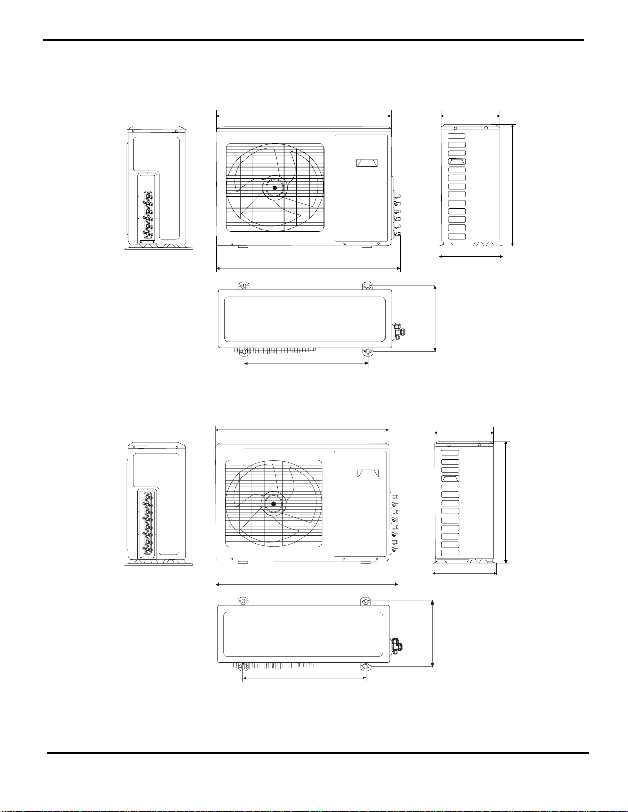
Constrction views
8
572
340
840
378
950
1018
572
412
840
378
950
1018
GMU028HXB-4
GMU028HXB-3
340
412

9
Refrigerant System Diagram
4. Refrigerant System Diagram
'
&
%
$
$
%
&
'
GMU018HXB-2
Refrigerant pipe diameter
Liquid : 1/4" (6 mm)
Gas :3/8" (9.52mm)
GMU024HXB-2
Refrigerant pipe diameter
Liquid : 1/4" (6 mm)
Gas :1/2" (12mm)
GMU028HXB-3,GMU024HXB-2
Refrigerant pipe diameter
Liquid : 1/4" (6 mm)
Gas :3/8" (9.52mm)
1/2" (12mm)
Indoor Unit
Outdoor Unit
Heat exchanger
Electric expansion valve
Filter
Electric expansion valve
Filter
Electric expansion valve
Filter
Electric expansion valve
Filter
Heat exchanger
Heat exchanger
Heat exchanger
Fan
Filter
High pressure liquid receiver
Note: it is not available for 1-to-2 model.
4-way valve
Outdoor heat exchanger
SP high pressure cut-out
Note: it is not available for 1-to-2 model.
Exhaust muffler
Discharge temp sensor
Gas-liquid separator
Variable speed compressor
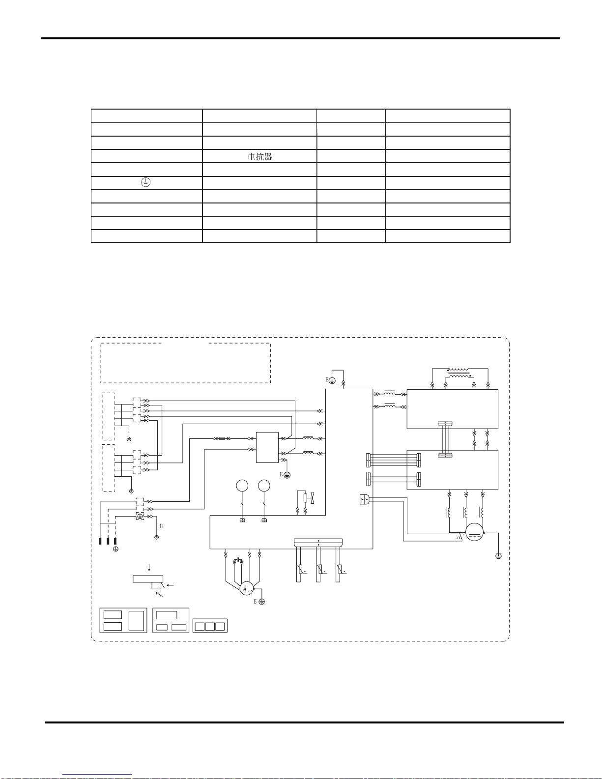
Schematic Diagram
10
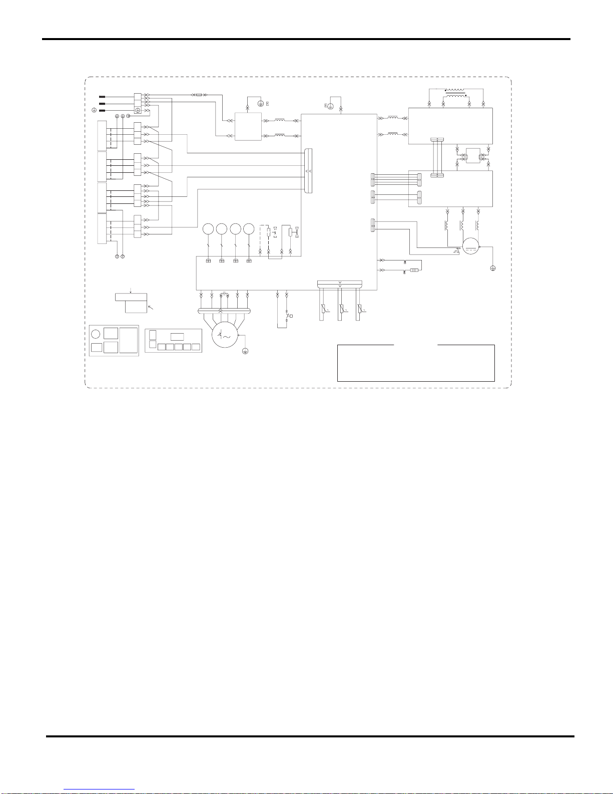
5. Schematic Diagram
5.1 Electrical Date
5.2 Electrical wiring
Symbol Parts name Symbol Color symbol
L1 L2
REACROR
WH
WHITE
YK
Four-way-Valve
YE
Y ELLOW
RD
RED
L
BN
SA T O VERLOA D BN BROWN
COMP
COMPRESSOR
BU
BLUE
PROTECTIVE EA RTH
BK
BLACK
YEGN
YELLOW G REEN
GY GRAY
AP4 Power Module
Drive BoardAP3
AP2 PFC Module
AP1 Main Board
XTA
XT1
XTB
3
2
N(1)
E
E
E
L2
3
2
L
L
N(1)
L2
C
C
0
0
0
FU1
2BN
FU1
ELECTRICAL BOX
A
A
B
B
C1
AP1
AP2
AP3
7BU
L1
YE
WH
BU
BN
AC-L1
LAC
15BN
AC-L3AC-N3AC-L1
AC-N1
14YEGN
X14
FAN MOTOR
BKWH
X25
S
C(T)
R
EXHAUST
TUBE
ROOM
OVERLOAD
X5
X101
X3
X12
XH-3
W34
W33
AC-N1
NAC
16BU
S1
20WH
19WH
4V
24YEGN
COMP.
23WH
22BU
21YE
18RD
17BK
V
U
W
N
N
P
PR
10GY
E
4BN
2
4
FILTER
6BU
1
3
1BN
3BU
AC-N
AC-L
X28
X13(COM-B)
X18(COM-A)
11BK
C1
BN
BN
BK
BU
WH
YEGN
8BU
9BN
POWER
INDOOR UNIT A
INDOOR UNIT B
WHEN THE UNIT IS RUNNING OR STOPED IN 2
MINUTES OR THE VOLTAGE LESS THAN 30V
BETWEEN P AND N OF IPM,PLEASE DON©T TOUCH
ANY TERMINAL,AVOIDING ELECTRICAL SHOCK HAZARD.
WARNING
5BN
XT1XTAXTB
Val.
MOTOR
FILTER
FBFA
FAN-L
FAN-H
X25
TEM.SENSOR
EXHAUST
TEM.SENSOR
OUTROOM
TEM.SENSOR
OUTTUBE
RT5
RT4
RT3
X4
W35
AP1
AP2
M2
AP3
4V
13YEGN
MOTOR
Val.
M1
YEGN
CN101 CN102
FA FB
OUTDOOR UNIT
Model GMU018HXB-2
11
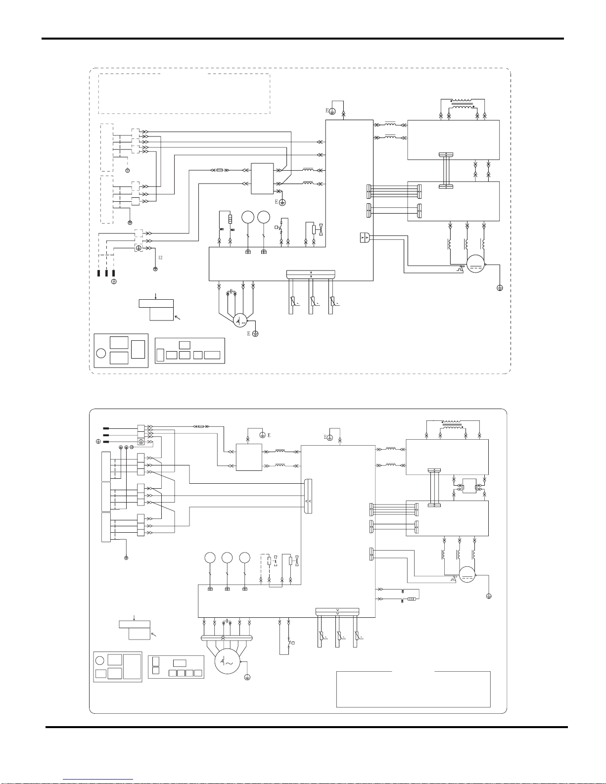
Schematic Diagram
Model GMU024HXB-2
XTA
XT1
XTB
3
2
N(1)
E
E
E
L2
3
2
L
L
N(1)
L2
0
0
0
WH
BU
BK
BN
BN
C1
FAN MOTOR
2BN
FU1
A
C1
B
ELECTRICAL BOX
A
B
7BU
L1
YE
WH
BL
BN
AC-L1
LAC
15BN
AC-L3AC-N3AC-L1
AC-N1
14YEGN
X14
S2
21BU
22YE
BKWH
S
C(T)
R
OVERLOAD
X5
X101
X3
X12
W34
W33
AC-N1
NAC
16BU
S1
24WH
23WH
28YEGN
COMP.
27WH
26BU
25YE
18RD
17BK
V
U
W
N
N
P
PR
10GY
4BN
2
4
FILTER
6BU
1
3
1BN
3BU
AC-N
AC-L
X13(COM-B)
X18(COM-A)
11BK
YEGN
8BU
9BN
POWER
INDOOR UNIT A
INDOOR UNIT B
WHEN THE UNIT IS RUNNING OR STOPED IN 2
MINUTES OR THE VOLTAGE LESS THAN 30V
BETWEEN P AND N OF IPM,PLEASE DON©T TOUCH
ANY TERMINAL,AVOIDING ELECTRICAL SHOCK HAZARD.
WARNING
5BN
HEATER
19RD
20RD
COMP
Val.
MOTOR
YEGN
M1
X25
FAN-H
FAN-L
FU1
FBFA
XTB
FILTER
XTA XT1
L1
AP3
AP2
AP1
X2
X8
AC-N
P
OVC
X25
TEM.SENSOR
EXHAUST
TEM.SENSOR
OUTROOM
TEM.SENSOR
OUTTUBE
RT5
RT4
RT3
EXHAUST
TUBE
ROOM
XH-3
X4
W35
4V
AP1
AP2
M2
AP3
4V
E
13YEGN
X28
MOTOR
Val.
CN101 CN102
FA FB
OUTDOOR UNIT
Model GMU028HXB-3
XTC
XTB
XT1
XTA
26BK
27RD
35BK
36RD
C(WH)
B(GY)
A(BK)
28BN
18YEGN
16BN
17BU
15BU
14BN
12WH
11GY
10BK
9YEGN
7BU
6BU
5BU
3BN
2BN
1BN
E
L
L2
3
2
N(1)
N(1)
2
3
YE
WH
BL
BN
20BN
19YEGN
21BU
29WH
30WH
34YEGN
33WH
32BU
31YE
E
L2
3
2
L
N(1)
PR
P
N
N
PR
N
0
0
FU
FU
XT1
XTC
BTXATX
INDOOR UNIT CINDOOR UNIT B
A
C1
B
ELECTRICAL BOX
A
B
L
AC-L1
AC-L3AC-N3AC-L1
AC-N1
S2
S(W)
C(T)
R
0
X5
X3
XH-3
X4
W38
W37
AC-N1
S1
COMP.
V
U
W
POWER
INDOOR UNIT A
WHEN THE UNIT IS RUNNING OR STOPED IN 2
MINUTES OR THE VOLTAGE LESS THAN 30V
BETWEEN P AND N OF IPM,PLEASE DON©T TOUCH
ANY TERMINAL,AVOIDING ELECTRICAL SHOCK HAZARD.
WARNING
E
N(2)
N©(4)
FILTER
P(1)
P©(3)
C1
M1
FAN MOTOR
COMP
HEATER
AP4
AP4
Val.
MOTORMOTOR
Val.
4V2V
BU BU VT VT
HEAT-C
X5
2V
AC-N
X29
X20
FBFA
Val.
MOTOR
FA FB
CN2
FC
FILTER
L
AP3
AP2
AP1
X2
X4
X6
X14
P
OVC
25BU
24YE
BKWH
X25
TEM.SENSOR
EXHAUST
TEM.SENSOR
OUTROOM
TEM.SENSOR
OUTTUBE
RT5
RT4
RT3
EXHAUST
TUBE
ROOM
OVERLOAD
X101
X12
W39
X1
X3
AP1
AP2
M2
AP3
4V
X9(AC-N)
X10(AC-L)
X28
22RD
23WH
FC
OUTDOOR UNIT
X1
213564
42BN
X11X7X8
FAN-M
40YE
FAN-L
FAN-H
X2
43BN
44BK
45BU
41WH
YEGN
E
Schematic Diagram
12
XTD
XTC
XTB
XT1
XTA
26BK
27RD
35BK
36RD
D(RD)
C(WH)
B(GY)
A(BK)
28BN
18YEGN
16BN
17BU
15BU
14BN
13RD
12WH
11GY
10BK
9YEGN
8BU
7BU
6BU
5BU
4BN
3BN
2BN
1BN
E
L
L2
N(1)
2
3
3
2
N(1)
N(1)
2
3
YE
WH
BL
BN
20BN
19YEGN
21BU
29WH
30WH
34YEGN
33WH
32BU
31YE
E
L2
3
2
L
N(1)
PR
P
N
N
PR
N
0
0
E
FU
FU
XT1
XTD
XTC
XTAXTB
M1
INDOOR UNIT DINDOOR UNIT CINDOOR UNIT B
A
C1
B
ELECTRICAL BOX
A
B
L
AC-L1
AC-L3AC-N3AC-L1
AC-N1
S2
FAN MOTOR
S(W)
C(T)
R
0
X5
X3
XH-3
X4
W38
W37
AC-N1
S1
COMP.
V
U
W
N(2)
N©(4)
FILTER
P(1)
P©(3)
C1
POWER
INDOOR UNIT A
WHEN THE UNIT IS RUNNING OR STOPED IN 2
MINUTES OR THE VOLTAGE LESS THAN 30V
BETWEEN P AND N OF IPM,PLEASE DON©T TOUCH
ANY TERMINAL,AVOIDING ELECTRICAL SHOCK HAZARD.
WARNING
COMP
HEATER
X1
213564
42BN
AP4
AP4
Val.
MOTOR
Val.
MOTORMOTOR
Val.
4V2V
BU BU VT VT
HEAT-C
X11X7X8
FAN-M
40YE
YEGN
E
X5
2V
AC-N
X29
X20
FBFA
Val.
MOTOR
FA FB
CN2
CFDF
FILTER
L
AP3
AP2
AP1
X2
X4
X6
X14
P
OVC
25BU
24YE
FAN-L
FAN-H
X2
BKWH
X25
TEM.SENSOR
EXHAUST
TEM.SENSOR
OUTROOM
TEM.SENSOR
OUTTUBE
RT5
RT4
RT3
EXHAUST
TUBE
ROOM
OVERLOAD
X101
X12
W39
X1
X3
AP1
AP2
M2
AP3
4V
X9(AC-N)
X10(AC-L)
X28
22RD
23WH
43BN
44BK
45BU
41WH
FC FD
OUTDOOR UNIT
Model GMU028HXB-4
These circuit diagrams are subject to change without notice. Please refer to the one supplied with the unit.
13
Schematic Diagram
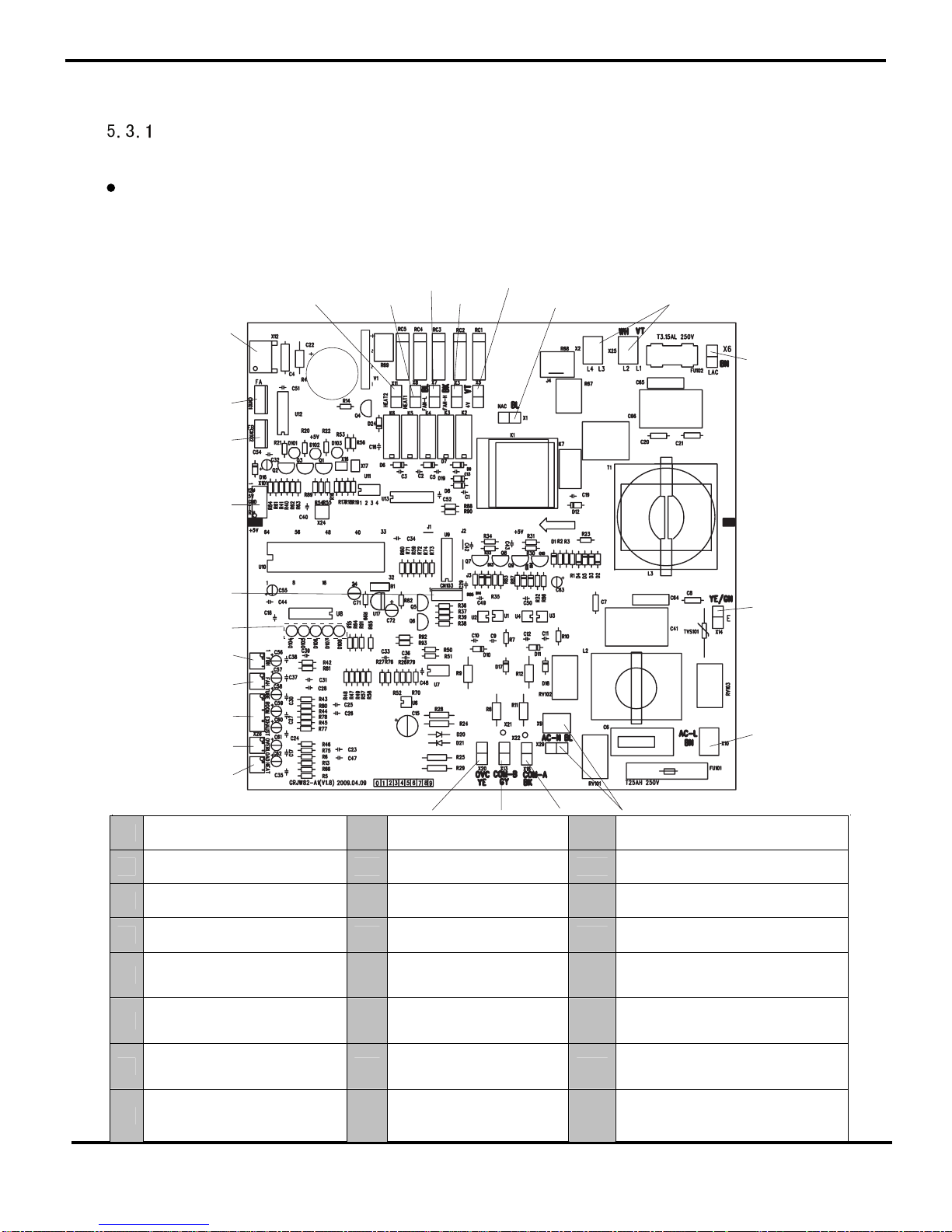
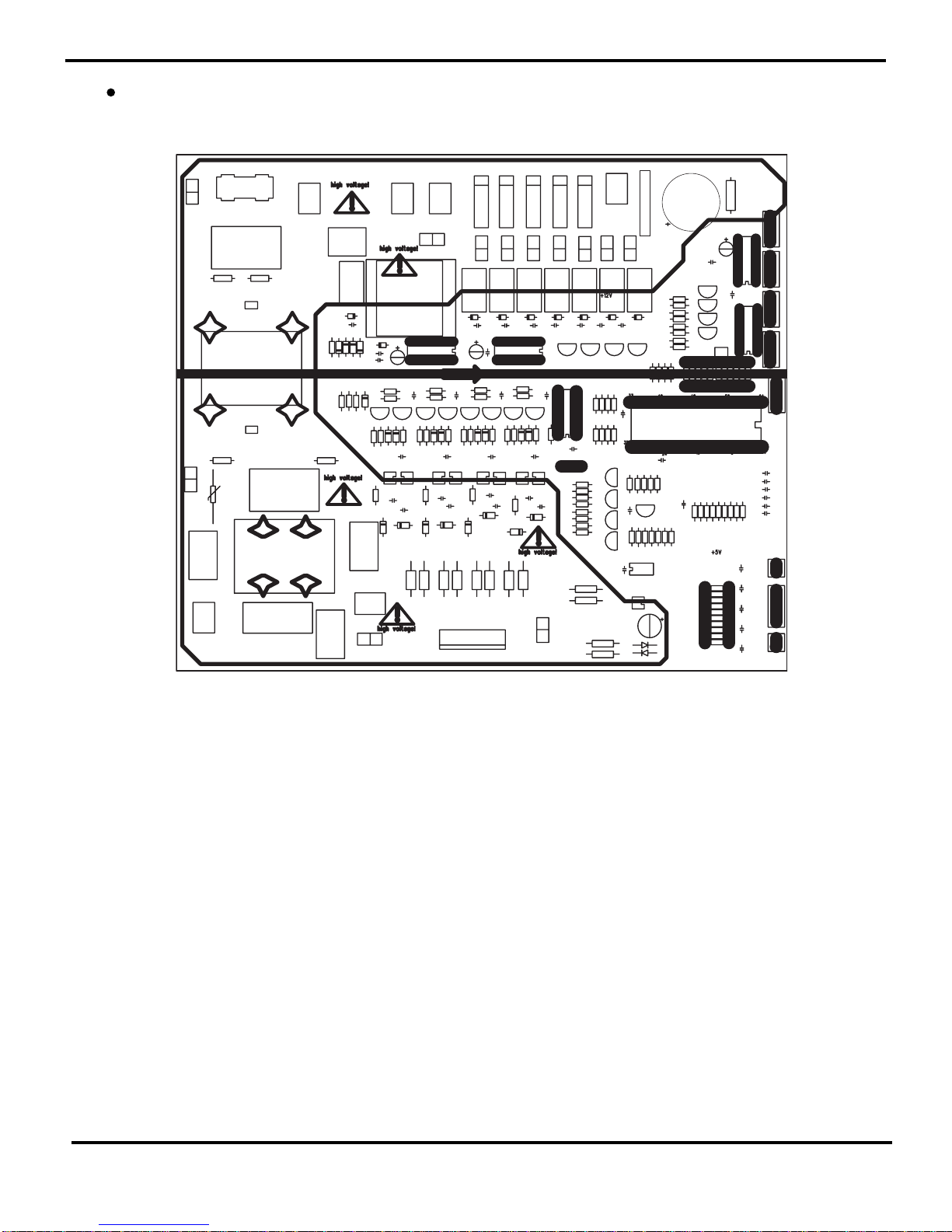
5.3 Printed Circuit Board
Model GMU018HXB-2,GMU024HXB-2
TOP VIEW
Mainboard
1
2
3
4
5
6
7
8
9
10
11
12
13
14
15
16
17
18
19
20
18
21
22
23
24
1 Electric heater on chassis(reserved) 9 Ground wire 17 Terminal of temp sensor
2 Heating tape of compressor (reserved) 10 Live wire 18 Reserved terminal
3 Low speed of fan 11 Null wire 19 Reserved terminal for adjusting frequency
4 High speed of fan 12 Communication terminal 20 Error LED
5 Wire of 4-way valve 13
Communication terminal for 1-to-2
model B unit(reserved)
21 5-core wire connecting to drive board
6 Null wire connecting to PFC board 14
High pressure protection
terminal(reserved)
22
Terminal for electric expansion valve
(reserved for 1-to-two units)
7
Null wire behind 3.15A, connecting to
4-way valve and fan
15 Reserved terminal 23 Terminal of electric expansion valve
8
Live wire behind wave filter,
connecting to PFC board
16
Terminal for compressor overload
protector
24
Terminal for 2-core wire connecting to drive
board. Input voltage of the complete unit is
AC220V. Voltage of the terminal is DC310V
Refrigerant System Diagram
14
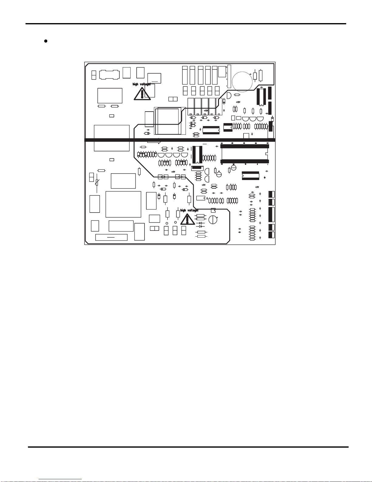
BOTTOM VIEW
15
Refrigerant System Diagram
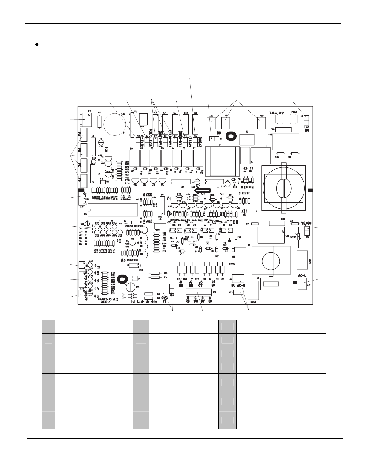
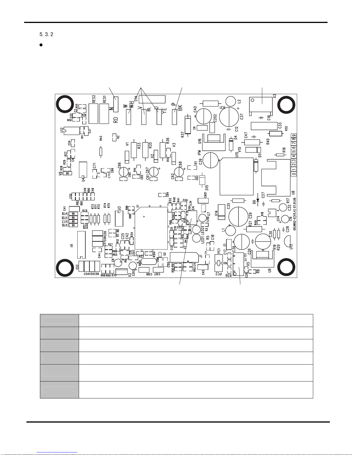
Model GMU028HXB-3,GMU028HXB-4
TOP VIEW
1
2
3
4
5
6
7
8
9
10
11
1213
14
15
16
17
18
19
20
1 Terminal for electric heater on chassis 8
Live wire behind wave filter,
connecting to PFC board
15 Temp sensor terminal
2
Terminal for pre-heating tape of
compressor
9 Ground wire 16 Reserved terminal for adjusting frequency
3 Connecting wire for fan 10 Live wire 17 Error LED
4 Terminal for 4-way valve 11 Null wire 18 5-core wire connecting to drive board
5 Terminal for by-pass valve(reserved) 12 Communication connecting wire 19 Terminal for electric expansion valve
6 Null wire connecting to PFC board 13
Connecting wire for high pressure
protector
20
Terminal for 2-core wire connecting to drive
board. Input voltage of the complete unit is
AC220V. Voltage of the terminal is DC310V
7
Null wire behind 3.15A, connecting to
4-way valve and fan
14
Terminal for compressor overload
protector
Schematic Diagram
16
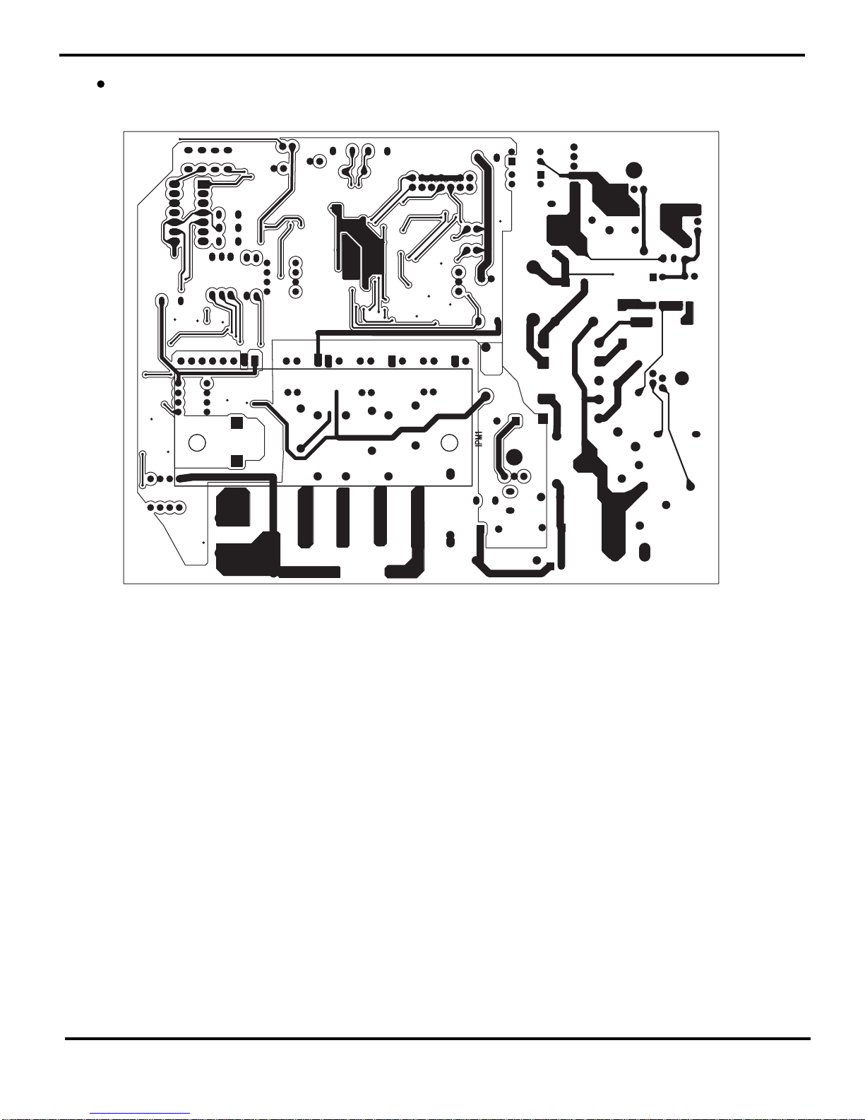
BOTTOM VIEW
17
Schematic Diagram
TOP VIEW
1
2
3
4
5
6
1 Negative terminal for input DC of PFC board
2 Terminals for three phases of compressor
3 Positive terminal for input DC of PFC board
4 Terminal for 2-core connecting wire of outdoor mainboard
5 Terminal for 5-core connecting wire of outdoor mainboard
6 Terminal for 3-core connecting wire of PFC board
Drive Board
Schematic Diagram
18
BOTTOM VIEW
19
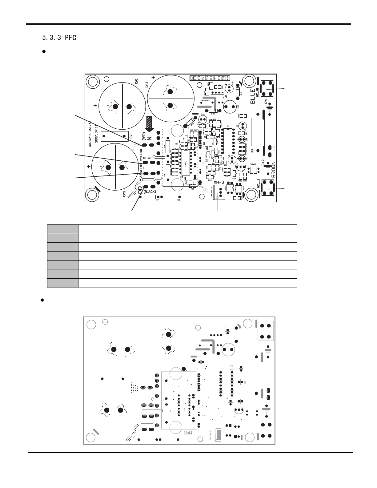
Schematic Diagram
TOP VIEW
BOTTOM VIEW
Board
1
2
3
4
5
6
7
1 Zero terminal of DC, connecting to blue wire of inductor and null wire of outdoor mainboard.
2 Live terminal of AC, connecting to brown wire of inductor and live wire of outdoor mainboard.
3 Terminal for control signal input b drive board
4 Positive terminal of DC of drive board
5 Terminal for white wire of inductor
6 Terminal for yellow wire of inductor
7 Negative terminal of DC of drive board
 Loading...