

GRT Avionics Horizon 10.1, Sport 10.1, Horizon HXr User Manual
Sport/Horizon 10.1
User Manual
Preliminary - September 2019
GRT Avionics, Inc.
3133 Madison Avenue SE
Wyoming, MI 49548
616-245-7700
support@grtavionics.com
www.grtavionics.com

GRT Avionics, Inc. September 2019
1 FOREWORD
Thank you for choosing the GRT EFIS!
This manual describes the operation of a Horizon 10.1 and Sport 10.1 EFIS using the
software version shown in the Record of Revisions. Some differences may be observed
when comparing the information in this manual to other software versions. The Sport 10.1
EFIS may optionally be equipped with synthetic vision and vertical autopilot command
capability. Every effort has been made to ensure that the information in this manual is
accurate and complete. GRT is not responsible for unintentional errors or omissions in the
manual or their consequences. The builder of the aircraft and the pilot have the final
authority on the airworthiness of the aircraft.
Information in this document is subject to change without notice. GRT Avionics, Inc.
reserves the right to change or improve their products and to make changes in the
content of this material without obligation to notify any person or organization of such
changes or improvements.
Copyright © 2001 - 2019 GRT Avionics, Inc. or its subsidiaries. All rights reserved.
1.1 Important Safety Information
!WARNING!: This is an Experimental EFIS system intended ONLY for use in experimental
and light-sport aircraft. Various functions of this system may be incomplete or untested
with your particular avionics combination. Exercise caution when using the EFIS after
installing new software updates. All software and hardware updates must be tested
thoroughly in VFR conditions before using for IFR flight.
!WARNING!: Obstacle clearance is NOT assured in Synthetic Approach mode.
*CAUTION*: If any display unit is inoperable in a multiple-display system, the display
units will not be able to share information and some features or instruments may become
disabled.
*CAUTION*: If GPS position data is lost for more than 30 seconds, the Sport issues a No
GPS Position warning and automatically reverts to dead-reckoning using the AHRS
heading, true airspeed, last known winds and time. This data is used to estimate changes
in position, which are applied to the last known GPS position to give an approximate
Sport/Horizon 10.1 Pilot’s Guide I Rev. Preliminary

GRT Avionics, Inc. September 2019
navigation solution. The accuracy of the dead- reckoning function will degrade with time
depending on the accuracy of this data and changes in the winds.
*CAUTION*: Dual Nav radios tuned to Localizer frequencies with autopilot function ARM
engaged will result in the EFIS Sport selecting either NAV radio to fly the Localizer.
Sport/Horizon 10.1 Pilot’s Guide II Rev. Preliminary

GRT Avionics, Inc. September 2019
1.2 Warranty and Return Policy
Satisfaction Guarantee
If for any reason you are unhappy with your GRT product, you may return it for a refund
anytime during the first 60 days you own it.
Please call EFIS Tech Support before returning any system or component.
Limited Warranty
All GRT products include a 2-year warranty starting on the day the instrument is put into
service (or three years after purchase, whichever comes first) against manufacturer defect.
Contact Tech Support before returning a display unit or component to GRT for repair or
warranty work. Many issues are installation-related and can be resolved over the phone,
saving expense. All returns for repair or upgrade must be accompanied by a Service
Request Form, downloadable from the GRT website Support section.
1.3 Technical Support
Our tech support staff has real-world experience installing, flying and troubleshooting
GRT equipment in many different types of aircraft. We are here to help you.
Please visit the Contact page of our website for up-to-date contact information for tech
support via email.
Check the home page of the GRT website often for new manual updates, video tutorials,
and other instructional materials as we release them.
Sport/Horizon 10.1 Pilot’s Guide III Rev. Preliminary

GRT Avionics, Inc. September 2019
EFIS
SW Revision
A
August 2019
3.00
Initial Release
1.4 RECORD OF REVISIONS
Revision Date
Description
Sport/Horizon 10.1 Pilot’s Guide IV Rev. Preliminary

GRT Avionics, Inc. September 2019
2 Contents
1 FOREWORD .............................................................................................................................................. I
1.1 Important Safety Information .................................................................................................... I
1.2 Warranty and Return Policy ..................................................................................................... III
Satisfaction Guarantee ...................................................................................................... III
Limited Warranty ................................................................................................................. III
1.3 Technical Support ........................................................................................................................ III
1.4 RECORD OF REVISIONS ............................................................................................................ IV
3 Introduction ........................................................................................................................................... 1
3.1 Revisions .......................................................................................................................................... 1
3.2 Warnings, Cautions and Notes ................................................................................................ 1
3.3 EFIS Control Sequence Instructions ....................................................................................... 1
3.4 Electronic Manuals and Internet Links .................................................................................. 2
3.5 Transition from Round Gauges to Glass Cockpit .............................................................. 2
3.6 Feedback and Corrections ......................................................................................................... 2
4 GENERAL SYSTEM INFORMATION ................................................................................................ 4
4.1 The Sport/Horizon 10.1 .............................................................................................................. 4
4.2 AHRS and Air Data Computer .................................................................................................. 6
Adaptive AHRS Operation ................................................................................................ 6
AHRS/Air Data Computer Limitations .......................................................................... 7
4.3 Optional Components and Software ..................................................................................... 8
EIS Engine Monitor .............................................................................................................. 8
GRT Autopilot ........................................................................................................................ 8
ARINC 429 Module .............................................................................................................. 8
GPS Receiver Compatibility .............................................................................................. 9
Synthetic Vision .................................................................................................................... 9
5 OPERATING THE EFIS ........................................................................................................................ 10
5.1 System Power-Up ....................................................................................................................... 10
5.2 The Pilot’s Controls .................................................................................................................... 11
Softkeys ................................................................................................................................. 11
Sport/Horizon 10.1 Pilot’s Guide V Rev. Preliminary

GRT Avionics, Inc. September 2019
Knobs ...................................................................................................................................... 12
Right Knob Short Cut Functions ................................................................................... 12
Remote Radio Rack and EFIS Shortcut Softkeys ..................................................... 13
5.3 The Settings Menu ..................................................................................................................... 17
Settings Menu Pages ........................................................................................................ 17
Adjusting Individual Settings ......................................................................................... 18
5.4 Display Page Groups ................................................................................................................. 20
Selecting the View ............................................................................................................. 20
Split Screen PFD View ....................................................................................................... 22
Full Screen PFD View ......................................................................................................... 23
Six Pack PFD View .............................................................................................................. 24
Full Screen Map View ....................................................................................................... 26
MAP and PFD Insets .......................................................................................................... 27
Split views of Plates ........................................................................................................... 30
Split Map/Engine View ..................................................................................................... 32
5.5 Single Screen Operation .......................................................................................................... 32
Single screen EFIS with no EIS or GPS navigator .................................................... 32
Single screen with an external GPS navigator ......................................................... 33
Single Screen with a non-Remote (display equipped) EIS .................................. 33
5.6 Dual Screen Operation ............................................................................................................. 33
Default Screen ..................................................................................................................... 34
Pilot’s Interaction with an EFIS ...................................................................................... 34
6 Primary Flight Display Description ............................................................................................... 36
6.1 Primary Flight Instruments on the PFD .............................................................................. 36
6.2 Secondary Information on the PFD ..................................................................................... 37
6.3 PFD View ........................................................................................................................................ 38
Overview ................................................................................................................................ 38
Central Elements ................................................................................................................. 39
Attitude Indicator/Artificial Horizon ............................................................................ 39
Attitude Reference Index ................................................................................................. 39
Sport/Horizon 10.1 Pilot’s Guide VI Rev. Preliminary

GRT Avionics, Inc. September 2019
Zenith and Nadir (+/- 90° Pitch Display) ................................................................... 40
Pitch Ladder Offset ............................................................................................................ 40
Sky Pointer ............................................................................................................................ 41
Turn Coordinator/Standard Rate Turn Indicator .................................................... 41
Slip Indicator ........................................................................................................................ 41
Flight Path Marker ......................................................................................................... 42
Airspeed Tape ................................................................................................................. 42
Altimeter Tape ................................................................................................................. 44
Vertical Speed Indicator .............................................................................................. 47
Heading Indicator .......................................................................................................... 47
GPS Cross-Track Deviation Indicator (CDI) ........................................................... 50
Selected Heading Bug .................................................................................................. 50
Wind Vector and Crosswind Component ............................................................. 50
G-Meter ............................................................................................................................. 51
Flap and Trim Indicators .............................................................................................. 54
Clock ................................................................................................................................... 55
Angle-of-Attack (AOA) Indicator .............................................................................. 55
6.4 Synthetic Vision Features and Settings .............................................................................. 59
Terrain .................................................................................................................................... 60
Obstacles ............................................................................................................................... 60
Runways ................................................................................................................................. 61
Grid Overlay ......................................................................................................................... 61
Traffic on PFD View ........................................................................................................... 62
Waypoint Balloons ............................................................................................................. 62
Course Ribbons ................................................................................................................... 63
Enroute Highway-in-the-Sky (HITS) ............................................................................ 63
7 Moving Map Description................................................................................................................. 65
Moving Map Database ..................................................................................................... 66
Map Screen Setup and Customization ....................................................................... 66
Flying with the Moving Map .......................................................................................... 70
Sport/Horizon 10.1 Pilot’s Guide VII Rev. Preliminary

GRT Avionics, Inc. September 2019
8 FLIGHT PLANNING AND NAVIGATION ...................................................................................... 83
8.1 Single GPS Navigation .............................................................................................................. 83
8.2 Multiple Navigation Inputs ..................................................................................................... 83
8.3 Selecting the EFIS Navigation Mode ................................................................................... 83
8.4 External Navigation Mode (EXTERN) ................................................................................... 85
8.5 GPS Navigation Mode (GPS/GPS1/GPS2) .......................................................................... 85
8.6 Loss of GPS Position .................................................................................................................. 86
8.7 Internal Vs. External Flight Plans ........................................................................................... 88
8.8 When to Use External Flight Plans ....................................................................................... 88
8.9 Flight Planning Terms ............................................................................................................... 89
8.10 Using Direct-To and Sequence Flight Plans ................................................................. 89
Direct-To Navigation .................................................................................................... 90
Sequential Flight Plans ................................................................................................. 93
8.11 External Flight Plans .............................................................................................................. 96
8.12 Horizontal Situation Indicator (HSI) ................................................................................. 97
8.13 Navigation Using VOR/LOC ..............................................................................................100
Initializing VOR/LOC Navigation ............................................................................100
Setting the Selected (OBS) Course ........................................................................100
VOR/LOC CDI Display Options on the PFD ........................................................101
9 Autopilot, Flight Director and Navigation Mode Display ................................................103
9.1 Overview -- No Servos Required… .....................................................................................103
9.2 Autopilot Mode and Target Selection ..............................................................................104
9.3 Selecting Autopilot Modes ...................................................................................................105
9.4 Selecting Autopilot Targets ..................................................................................................106
First Autopilot Menu .......................................................................................................106
Second Autopilot Menu.................................................................................................107
9.5 Engaging the Autopilot ..........................................................................................................107
Autopilot Shortcut Menu ..............................................................................................107
9.6 Mode Display .............................................................................................................................108
Lateral Autopilot Mode and Target Annunciation ...............................................109
Sport/Horizon 10.1 Pilot’s Guide VIII Rev. Preliminary

GRT Avionics, Inc. September 2019
Vertical Autopilot Mode and Target Annunciation .............................................109
9.7 Color Coding ..............................................................................................................................110
10 Remote Transponders ....................................................................................................................111
10.1 Accessing Transponder Controls ....................................................................................111
Setting the Transponder Code ................................................................................113
10.2 Transponder Display ...........................................................................................................114
10.3 Squawk and Mode Control from Multiple Display Units .......................................115
10.4 Redundant Transponder Controllers .............................................................................115
11 Graphical Engine Monitoring .......................................................................................................116
11.1 How to use the Graphical Engine Monitoring ...........................................................116
11.2 Graphical Engine Monitoring Displays .........................................................................117
Types of Engine Displays ...........................................................................................118
Engine Monitoring Strip ............................................................................................120
Engine Display Elements ...........................................................................................121
11.3 CHT/EGT Tools ......................................................................................................................122
What and Why of CHT/EGT Time History ...........................................................122
CHT/EGT Time History Display ................................................................................122
EGT Increase and Decrease Alarms .......................................................................124
11.4 Fuel Efficiency and Management Tools .......................................................................125
Recommended Fuel Display Configuration ........................................................125
Configuring the Fuel (combined) Dial ..................................................................125
Lean Assist ......................................................................................................................126
Fuel Flow, Totalizer and Fuel Level Displays.......................................................127
Interval Alarm ................................................................................................................130
Engine Efficiency Measurement Using SFC ........................................................130
Percent Power ...............................................................................................................132
12 GPS/VOR/ILS APPROACHES .........................................................................................................134
12.1 Displays During Approach ................................................................................................134
12.2 GPS Approach ........................................................................................................................136
Automatic Capture of GPS Approach Glideslope.............................................136
Sport/Horizon 10.1 Pilot’s Guide IX Rev. Preliminary

GRT Avionics, Inc. September 2019
GNAV Lateral Autopilot Mode ................................................................................136
12.3 NAV (Radio) Mode ...............................................................................................................136
LOC and VOR Course Pointer ..................................................................................137
ILS—Localizer/Glideslope Mode ............................................................................137
Autopilot/Flight Director Coupling to the ILS ...................................................137
Automatically Coupling to the ILS with the ARM Feature ............................138
Flying the Localizer Back-Course Using the LOC-REV ARM Feature .........138
Automatic Localizer Course Setting ......................................................................141
12.4 VOR Navigation Mode .......................................................................................................142
12.5 ILS Approach Examples ......................................................................................................143
Vectors to Localizer .....................................................................................................143
GPS Enroute to Localizer ...........................................................................................143
VOR Enroute to Localizer (Two Nav Receivers) .................................................144
VOR Enroute to Localizer (One Nav Receiver) ...................................................144
Back-Course with LOC-REV ARM Feature ...........................................................145
Precision Approaches (Glideslope Coupling to Autopilot) ...........................145
Non-Precision Approaches—Stepping Down ...................................................146
12.6 VFR and IFR Approaches Using Synthetic Approach ..............................................146
The Synthetic Approach Lateral Path ...................................................................147
The Synthetic Approach Vertical Path ..................................................................147
Activating the Synthetic Approach ........................................................................148
Manual Runway Selection .........................................................................................148
Transitioning from Enroute to Synthetic Approach ........................................149
Step-By-Step Synthetic Approach Activation ....................................................150
Autopilot-Coupled Synthetic Approaches ..........................................................152
When is a Synthetic Approach Unavailable? ......................................................155
Synthetic Approach During LOC/ILS Approaches ............................................155
13 Checklists ............................................................................................................................................156
13.1 Using the Checklist ..............................................................................................................156
13.2 Loading a Checklist ..............................................................................................................156
Sport/Horizon 10.1 Pilot’s Guide X Rev. Preliminary

GRT Avionics, Inc. September 2019
Recommended Checklist Names ...........................................................................156
Live Data in the Checklist ..........................................................................................158
Sample Checklist ..........................................................................................................159
14 ALARMS, ALERTING AND STATUS .............................................................................................160
14.1 On-Screen Messages ..........................................................................................................160
Acknowledging an Alarm ..........................................................................................161
Inhibiting an Alarm ......................................................................................................161
14.2 Audio Alerting .......................................................................................................................162
Automatic Inhibiting After Takeoff ........................................................................162
Setting Up Audio Alerting.........................................................................................163
14.3 Status Page .............................................................................................................................164
15 DATA RECORDING ...........................................................................................................................165
15.1 Recording a Screen Snapshot ..........................................................................................165
15.2 Demo Recordings .................................................................................................................166
DEMO Settings ..............................................................................................................166
Starting and Saving Recordings Manually ..........................................................167
Playing or Extracting Data from Demo Recordings .........................................167
15.3 Automatic Demo Recordings ...........................................................................................169
USB Flight Data Logger (Black Box Feature) ......................................................169
Legal Considerations of Data Recording .............................................................170
15.4 Backing Up EFIS Settings ...................................................................................................170
16 Altimeter Calibration .......................................................................................................................173
16.1 Partial Altimeter Calibration – Correcting Altimeter vs Baroset ..........................173
16.2 Full Altimeter Calibration – Using Air Data Test Set ................................................174
17 A Typical Flight EFIS (Read if you don’t like manuals!) .......................................................176
17.1 Startup ......................................................................................................................................176
17.2 Runup .......................................................................................................................................176
17.3 Takeoff ......................................................................................................................................177
17.4 Initial Climb .............................................................................................................................177
17.5 Entering the Flight Plan? ....................................................................................................178
Sport/Horizon 10.1 Pilot’s Guide XI Rev. Preliminary

GRT Avionics, Inc. September 2019
17.6 Resetting the Direct-to .......................................................................................................178
17.7 Climbing and Overheating ................................................................................................179
17.8 Setting power and Leaning ...............................................................................................179
17.9 Cruise Checks .........................................................................................................................180
17.10 Checking Weather Enroute ...............................................................................................180
17.11 You do use the Interval Timer, right? ............................................................................181
17.12 Planning for Landing ...........................................................................................................181
17.13 Descent ....................................................................................................................................181
17.14 Landing ....................................................................................................................................182
17.15 Take it home with you! .......................................................................................................183
Sport/Horizon 10.1 Pilot’s Guide XII Rev. Preliminary

GRT Avionics, Inc. September 2019
3 Introduction
This manual was written to help both original builder/pilots and subsequent owners of
experimental aircraft learn how to use and customize the EFIS. The system can be used in
many types of aircraft and for many different types of flying. While we do our best to
cover all the information pilots need to know, one manual cannot cover all scenarios for
installation and use with third-party radios, GPS units, autopilots and other items.
3.1 Revisions
The manuals are always a work in progress as software changes are made to incorporate
new features in the EFIS system. New updates of this and other GRT manuals are published
in the Documentation section of our website as they are completed. The Record of
Revisions page in the beginning of the manual details which changes were made and
which pages or sections were affected. If you keep a printed copy of the manual, you can
update only the pages that were changed.
3.2 Warnings, Cautions and Notes
Throughout this manual, you will see notes punctuated with the following bold type:
!WARNING!: A special notice that could lead to injury or death if not followed.
*CAUTION*: A notice that could lead to damage of equipment if not followed.
NOTE: An item of special interest that is not immediately apparent through normal usage.
3.3 EFIS Control Sequence Instructions
Many tasks require that a sequence of softkeys, or buttons, be pressed. Softkey labels and
controls are typed as they appear on the EFIS screen and separated by a > symbol. For
example:
Press MORE > Set Menu > Primary Flight Display
Softkey labels are displayed with any button is pressed, but since the three left-most
buttons can be configured to be active when the labels are not displayed, we suggest you
Sport/Horizon 10.1 Pilot’s Guide 1 Rev. Preliminary

GRT Avionics, Inc. September 2019
use either of the rightmost two buttons to activate the softkey labels. The softkey label
timeout period is user adjustable.
After bringing up the softkey labels, press the NEXT softkey to bring up additional sets of
softkey labels. Depending on how your EFIS is configured, the number of times you must
press the “NEXT” softkey may vary to find the next softkey. Press the NEXT softkey as
many times as necessary until you find the “Set Menu” softkey.
Now press Set Menu softkey, and the set menu will be displayed. In this example, “Primary
Flight Display” is a choice in a scrollable list of items on the screen. As indicated on the
screen, use the right knob (turn to select, press to activate) to access the Primary Flight
Display menu page and complete your task.
3.4 Electronic Manuals and Internet Links
Many customers now choose to store electronic copies of the manuals on a tablet
computer or phone for easy access to the newest material. It is easy to carry a lot of written
materials aboard the aircraft without the added weight and bulk of paper. Because of this,
we have added links to videos and other aids to the manual text. Simply touch or click on
the link to access interactive materials and tutorials.
3.5 Transition from Round Gauges to Glass Cockpit
Digitization of flight instrumentation can build a subtle trap for pilots new to EFIS systems.
EFIS systems can present so much information that the line between enhanced situational
awareness and information overload can become blurred. At all times FLY THE AIRPLANE
FIRST! Guard against letting any EFIS system become a "heads down display.” Aviate,
navigate, communicate, and compute - in that order. Dual instruction with a qualified
flight instructor with experience behind an EFIS will ease the transition to a glass cockpit
and help you get the most out of your new system. Keep in mind that the airplane can be
flown from the primary flight page without pushing any buttons, and the usual six-pack
data is all shown on that screen.
3.6 Feedback and Corrections
If you notice any errors or would like a better explanation of something that relates to
your EFIS system, please contact GRT tech support. We are always striving to make our
customers’ lives easier.
Sport/Horizon 10.1 Pilot’s Guide 2 Rev. Preliminary

GRT Avionics, Inc. September 2019
Sport/Horizon 10.1 Pilot’s Guide 3 Rev. Preliminary

GRT Avionics, Inc. September 2019
4 GENERAL SYSTEM INFORMATION
4.1 The Sport/Horizon 10.1
In addition to its display and interface functions, the EFIS includes an internal
attitude/heading reference system (AHRS) which replaces the traditional gyros for
attitude and direction, and an air data computer for measuring airspeed, altitude,
vertical speed, and optionally, angle-of-attack. It also accepts AHRS/Air Data from an
external GRT AHRS/air data computer. A second internal AHRS is an option with the
Horizon 10.1.
The functions provided by the Sport 10.1 EFIS vary depending on the software/hardware
options included with the EFIS. Software options may be expanded at any time without
removing the unit from the airplane, and this is sometimes true of hardware options
also. Check the website for option pricing or call use for more details.
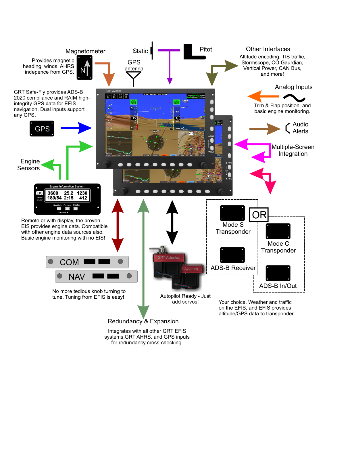
The EFIS may be used alone, as is common in VFR and some IFR airplanes (with
appropriate back-ups), or together with another Horizon/Sport 10.1, Sport EX, GRT Mini,
or HX as part of a system. The following figures illustrate typical system configurations.
Installation is quick and simple as the internal AHRS/air data computer means these do
not require separate mounting. In the most basic installations, the EFIS is ready to fly when
power/ground and pitot/static connections are made since all sensors are internal to the
EFIS. Engine monitoring is also supported with a serial data connection to any model of
the GRT Avionics EIS engine monitor.
Sport/Horizon 10.1 Pilot’s Guide 4 Rev. Preliminary
GRT Avionics, Inc. September 2019
The Sport/Horizon 10.1 supports basic single screen panels as well as multiple screen
redundancy using any combination of GRT EFIS systems, AHRS, and sensors, making it
easy to grow your panel with your budget. Multiple-screen integration shares pilot inputs
between screens and data that is only connected to one screen.
Sport/Horizon 10.1 Pilot’s Guide 5 Rev. Preliminary

GRT Avionics, Inc. September 2019
4.2 AHRS and Air Data Computer
Traditional spinning gyros are replaced by the internal Attitude/Heading Reference
System (AHRS) to provide roll and pitch (attitude) reference and gyro heading slaved to
magnetic heading (when a magnetometer is connected). The GRT Avionics AHRS features
the ability to operate without external aiding from GPS or air data – a feature that
preserves the integrity of this critical data even when air data or GPS is corrupted, and
exclusive to GRT Avionics among experimental aircraft instrument manufacturers.
The aircraft’s pitot/static system connects to the air data computer inputs at the rear of
the display unit for measurement of indicated airspeed, altitude and vertical speed.
Additional calculations within the EFIS provide true airspeed and winds (when magnetic
heading is available).
The AHRS and air data computer are located with the display unit, simplifying installation
of the system.
Adaptive AHRS Operation
The angular rate maximum of 250 deg/second is impossible to exceed with all airplanes
except highly aerobatic airplanes, and even those can exceed these limits only with
aggressive maneuvering. If angular limits are exceeded, the attitude information is
removed until the AHRS recovers from the attitude errors that could be induced. The air
data (airspeed and altimeter) will remain valid.
After power-up the AHRS will enter alignment and will provide attitude data once this
process is complete. With minimal movement of the airplane attitude data is usually
available by the time the EFIS completes booting. Continuous movement can extend the
alignment time.
Sport/Horizon 10.1 Pilot’s Guide 6 Rev. Preliminary

GRT Avionics, Inc. September 2019
AHRS/Air Data Computer Range Limits
Max. Angular Rate:
200-250°/s, All Axis Simultaneously
Airspeed (Standard):
35-285 mph
Airspeed (High-speed):
50-580 mph
Altitude:
-1,000 to 32,000 feet
Voltage:
9-35VDC
Operational Temperature:
-13°F to 158°F (-25°C to 70°C)
AHRS/Air Data Computer Limitations
The AHRS/Air Data Computer have the following range limits:
Sport/Horizon 10.1 Pilot’s Guide 7 Rev. Preliminary

GRT Avionics, Inc. September 2019
4.3 Optional Components and Software
EIS Engine Monitor
The GRT Avionics EIS Engine Monitor provides all
engine data to the EFIS. The Sport uses this data to
drive its graphical engine display and compute
additional engine performance information. The EIS is
available with or without a display. Data is transmitted
to the EFIS through a single RS-232 serial output.
When Data Recording is enabled in the Sport, EIS data is recorded to the USB stick and
can be analyzed by computer programs or web-based engine analyzers such as
SavvyAnalysis.com.
GRT Autopilot
The GRT Sport comes standard with 2-axis autopilot
software for driving GRT servos. The Sport is also
compatible with third-party autopilots, such as TruTrak and
Trio. While the Sport interfaces well with these autopilots
using the GRT servos provides superior performance and
simpler operation. The autopilot includes lateral functions
for heading select and following any navigation sources
(GPS, localizer, and VOR). The Sport’s standard vertical
autopilot function includes only altitude hold, but vertical
Commands for climbs, descents, and glideslope coupling
(including coupling to the EFIS generated synthetic approach) is an optional software
upgrade. Learn more about the GRT Autopilot in the dedicated autopilot manuals,
downloadable from the grtavionics.com.
ARINC 429 Module
When equipped with an optional ARINC 429 module, the Sport
can interface with avionics that require ARINC 429
communication, such as IFR GPS navigation units from Garmin
and Avidyne, as well as coupling to the vertical channel of
external autopilots, TCAS and TIS-A equipped transponders.
Sport/Horizon 10.1 Pilot’s Guide 8 Rev. Preliminary

GRT Avionics, Inc. September 2019
GPS Receiver Compatibility
The Sport/Horizon 10.1 is intended to be used with an external GPS receiver. The EFIS
supports two inputs for redundancy. The external GPS can be a remote unit (no display),
or a stand-alone GPS navigator that does allow the pilot to enter a flight plan. Practially
all GPS receivers provide a serial output that is compatible with the EFIS.
For installations that requires an FAA accepted GPS for ADS-B output, we recommend the
GRT Safe-Fly GPS 2020 complaint GPS. Unlike other 2020 compliant GPS sources, the SafeFly allows the EFIS to display accuracy and integrity indications that cannot be provided
from other 2020 complaint sources. In addition, the Safe-Fly includes a serial port
combiner that adds additional serial inputs to the EFIS.
Synthetic Vision
Synthetic vision is a software option in the Sport and standard in the Horizon. The Sport
provides a 10-mile synthetic vision range, while the Horizon provides 30 miles. Pilots with
Synthetic Vision enjoy a virtual “view out the windshield” featuring terrain, obstacles,
runways, waypoints, and when equipped with ADS-B or TIS, 3D traffic icons.
Sport/Horizon 10.1 Pilot’s Guide 9 Rev. Preliminary

GRT Avionics, Inc. September 2019
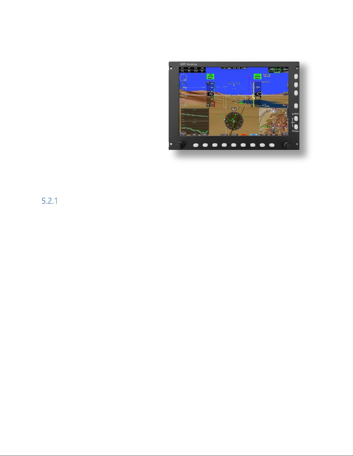
Boot screen of the EFIS upon power-up.
(Demo unit boot screen shown.)
5 OPERATING THE EFIS
5.1 System Power-Up
The EFIS is normally wired to the
avionics bus and will boot up with
this bus is powered.
Power may be applied before or after
the engine is started without damage
to the EFIS, however voltage drops
while starting the engine will usually
cause it to reboot. This makes it
preferable to leave the EFIS (and all
other avionics) off during engine
start.
After power-up, the “Startup Accept” screen will show software and navigation database
version and GRT system status. Check the navigation database date to make sure it is not
more than 60 days old. New nav database updates are posted on the GRT Avionics website
every 60 days. Instructions for updating it can be found in Section 10 of this manual. Press
the Accept softkey to continue.
NOTE: The “Startup Accept” screen is not shown if the EFIS is powered-up in-flight.
During the boot-up of the EFIS the AHRS will begin its alignment automatically. For more
details about the AHRS alignment period and startup, see the AHRS and Air Data
Computer section above.
Sport/Horizon 10.1 Pilot’s Guide 10 Rev. Preliminary
GRT Avionics, Inc. September 2019
Labels are shown above the rotary knobs and
no label exists, they have no function.
5.2 The Pilot’s Controls
The pilot controls the EFIS using
knobs (they turn and push) and
softkeys. The softkeys illuminate for
night flying.
white softkeys identifying their function. When
Softkeys
The function of the softkeys are identified by the label adjacent to them. Softkeys without
labels have no function until a label appears above them.
The labels for the softkeys are color-coded to make certain functions easy to identify. Blue
softkey labels are used for navigating “BACK” one menu level, or to the “HOME” or top
level menu.
Light blue is used to identify the “BARO” set function. It is the only softkey with this
colored label.
All top-level (or Home) softkeys on the bottom row with brown backgrounds can be
pressed to observe their submenu and pressed again to return back to home. You will
note that the sub-menus for these keys always becomes the “HOME” softkey when it is
pressed. This is handy feature that makes it easy to see what options each of these
softkeys provide without altering any setting in the EFIS.
In some cases, a “Long-Click”, holding the softkey pushed for more than a second, will
perform a secondary “shortcut” function. The “Screen” and “Inset” softkey are examples
of keys that have this feature. In most cases the shortcut feature will be displayed above
the softkey label when it is depressed. The remote radio rack selector is an exception, as
described below.
Sport/Horizon 10.1 Pilot’s Guide 11 Rev. Preliminary
GRT Avionics, Inc. September 2019
Knobs
Knobs provide selections by turning, and activation by pressing them. They always include
a label above them to identify their function. The knob functions from the top level menu
provide commonly used functions. In the case of the left knob, it sets the selected heading.
Even when the EFIS is not equipped with servos, or connected to an external autopilot,
this knob drives the flight director, and function that simplifies hand flying. We encourage
you to read more about this.
Right Knob Short Cut Functions
When on the PFD or Map pages, pressing the right knob provides shortcuts to commonly
used functions:
PFD: The Autopilot/Flight Director Menu
will appear when the right knob pressed.
MAP: The softkeys become the shortcut
menu, providing “Waypoint Details”
(information about the current goto
waypoint), direct-to waypoint selection,
the nearest list, and waypoint creation.
Sport/Horizon 10.1 Pilot’s Guide 12 Rev. Preliminary
GRT Avionics, Inc. September 2019
Pressing this softkey selects
Selection of the comm
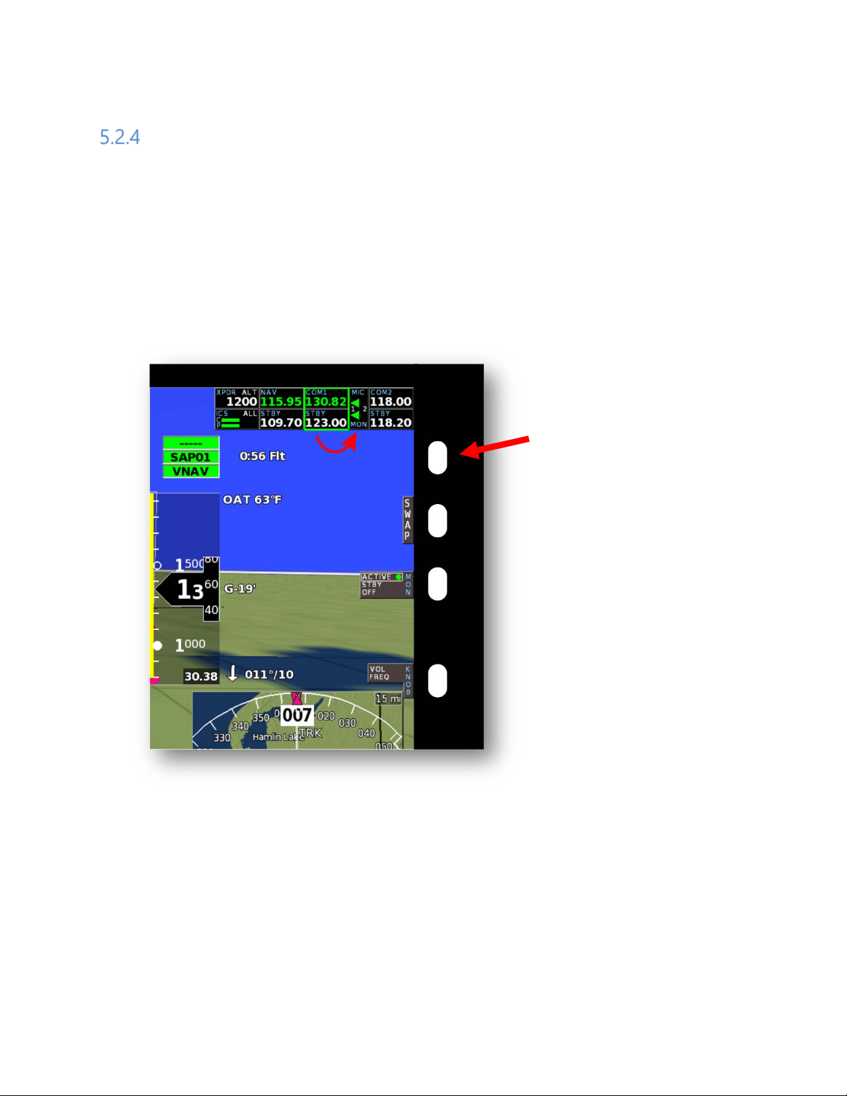
Remote Radio Rack and EFIS Shortcut Softkeys
Any remote radio rack devices connected to a display unit will be displayed in the upper
right portion of the EFIS. Other display units capable or remote radio rack functions that
are communicating with this display unit will also show these remote devices. Remote
radio rack devices include communication or navigation radios, remote transponder, or
intercom that are configured to communicate (via serial interfaces) with the EFIS.
5.2.4.1 Device Selector and its Shortcuts
the next remote radio rack
device.
radio or transponder is
normally made using the
long-click shortcut. See text.
Com1 shortcut - A long-press (more than 1 second) of the device selector selects
communication radio 1, if installed. Otherwise it selects the transponder.
Transponder shortcut – When com radio 1 is selected, a long-click of the device selector
selects the transponder.
EFIS Shortcut softkeys are provided instead of radio rack functions when the selector is
not displayed. This is always the case when no radio rack devices are connected, or by
Sport/Horizon 10.1 Pilot’s Guide 13 Rev. Preliminary
GRT Avionics, Inc. September 2019
With the green selector box
of the remote radio you are
repeatedly pressing the device selector until the green selector box is off. If the remote
radio rack does not include a com radio and transponder, a long click of the device
selector when the COM or transponder is currently selected will turn off the green selector
box and display the EFIS shortcut functions.
Our preference is to leave the device selector on the COM1 radio, as radio tuning is a
common EFIS function. If the remote app is being used for radio control (via a connected
android device), then we prefer selecting the selector off to make the EFIS shortcut
functions available.
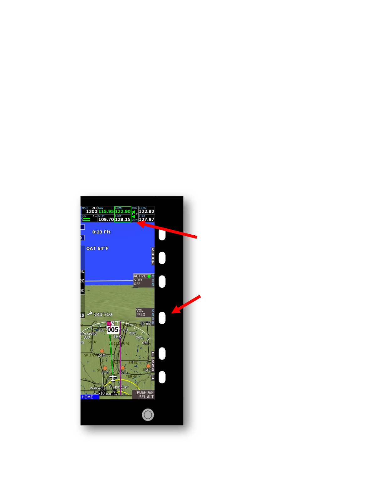
5.2.4.2 Controlling Remotes (10.1 Horizon)
Once a device is selected, softkeys and the lower right knob provide controls typical of
any radio (or audio panel).
highlighting the COM1
radio, the upper right
softkeys become controls
for this radio.
Pressing the “KNOB” button
selects the function for this
knob, as shown in the next
section.
(The exact controls provided
will vary with the capabilities
Sport/Horizon 10.1 Pilot’s Guide 14 Rev. Preliminary
GRT Avionics, Inc. September 2019
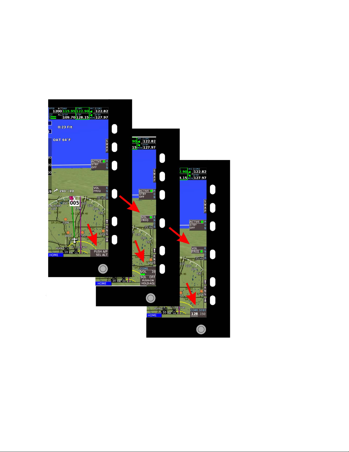
The “KNOB” softkey
5.2.4.3 Radio Rack Volume and Tuning Knob
For communication and navigation radios, volume and tuning is made using the right
knob. The knob function is selected using the “KNOB” softkey as shown below.
The knob function will return to normal (not volume or tuning) when the swap softkey is
pressed or after a timeout period. This returns the right knob to the commonly used
autopilot controls on the PFD, and Map options and shortcuts on the MAP page.
controls the lower right
knob function for
remote radio rack
devices.
Sport/Horizon 10.1 Pilot’s Guide 15 Rev. Preliminary
GRT Avionics, Inc. September 2019
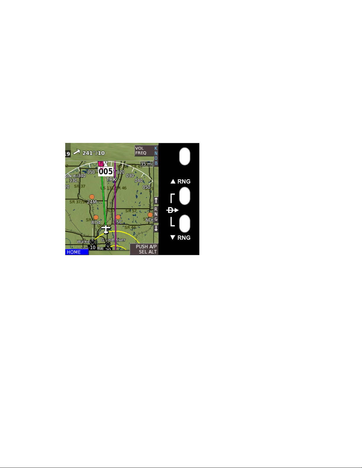
the “FLT PLAN” softkey.
5.2.4.4 Direct-To/Map Range Softkeys
Pressing both map range buttons together provide a shortcut to specifying a direct-to for
the direct-to (single waypoint) flight plan.
The map range softkeys control the range of the map on the full screen map page, the
split screen PFD/MAP/Engine page, and of the inset. The traffic inset has its own range
buttons on the traffic inset softkey menu.
This direct-to selection sets the
goto for the direct-to flight
plan. To “go direct” to a
waypoint in the sequence flight
plan, select the flight plan from
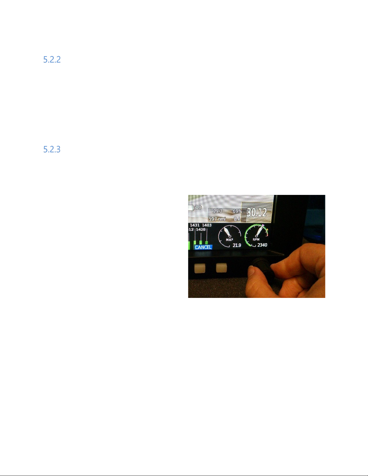
5.2.4.5 Dimming the Screen
To change the screen brightness, press the “Screen” softkey from the top menu. The left
knob will be labeled as “DIM”. Turn it as necessary to dim the screen. A dimming value of
1-10 is displayed in the upper left corner of the screen.
5.2.4.6 Rebooting the Screen
In the unlikely event a of a serious software fault, the EFIS will automatically restart itself.
This process is very fast (a few seconds) and will return the EFIS to the page it was
previously on. It is unlikely you would ever encounter this.
In the even less likely event that the automatic recovery failed to detect the serious
software fault, causing the screen to stop responding, the EFIS can be rebooted using the
front panel softkeys. To force a re-boot, press and hold the outer left and outer right white
softkeys at the same time to reboot the display unit. Since this action does not affect the
Sport/Horizon 10.1 Pilot’s Guide 16 Rev. Preliminary

GRT Avionics, Inc. September 2019
All GRT EFIS systems can be re-
screen.
AHRS, it will continue to provide attitude data without interruption, thus attitude data will
be available when the EFIS finishes re-booting. This re-booting process will take about 30
seconds.
booted by pressing and holding
the two outer softkeys. This is
illustrated here with a 6.5”
5.3 The Settings Menu
Settings, preferences and calibration for the EFIS are found on the Set Menu pages. To
access:
1. Press “MORE” and then “SET MENU”.
2. Turn either knob to move the cursor down the list. Press the knob to view the
highlighted page or make changes to the values of highlighted settings.
Settings Menu Pages
The Settings Menu contains the following pages (Note that if your system has autopilot
enabled, you will also have an A/P Maintenance menu page):
• General Setup: Serial port assignments, units of measure, clock, data recording,
etc…
• Primary Flight Display: V-speed settings, PFD display preferences and G-meter
settings.
• Moving Map: Map symbol and features preferences.
Sport/Horizon 10.1 Pilot’s Guide 17 Rev. Preliminary
 Loading...