

GRS 003-687 Installation Manual
Camera Mount INSTALLATION PART #003-687
for GRS Acrobat Microscope Stand
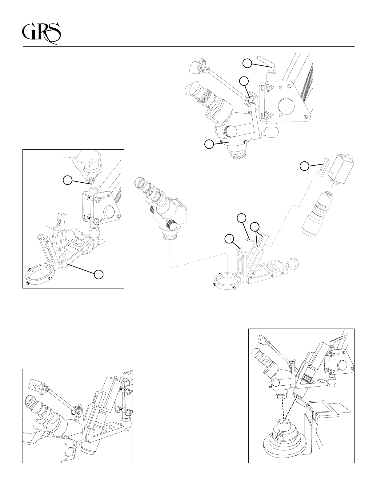
To begin the installation process of the Camera
Mount, you must first remove the ring light if one
is used. Next, loosen the screws surrounding
the Acrobat mounting ring (A), and remove the
microscope from the ring.
Unscrew the adjustable handle (B), which holds
the microscope mounting ring and headrest
assembly (C), by turning counter clockwise to
the Acrobat mounting post located at the front of
the microscope stand. The long stem screw and
cupped washer will now be free, lay them aside.
You will use them when re-attaching the
camera mount.
B
A
B
C
E
D
Install the camera mount assembly (D) and gently snug
the adjustable handle (B) clockwise so this assembly will
not move when attaching the camera and lens.
This mount comes with two adapters (E): one is for the
2" x 2" body camera (0.506" #044-094); the other is for
the 1 11/16" x 2" camera (0.350" #044-093). These two
adapters vary in the thickness of the material to allow the
camera/lens assembly to stay centered in the open area
where the lens passes through.
Transfer the headrest from the old
microscope holder assembly (F) and
tighten gently.
G
H
F
Mount the camera using the correct
mount bolt (G) and adapter (E) and
leave it slightly loose. Adjust the
camera using the set screws (H)
to insure the camera has the same
view as the microscope.
LIT-289

Camera Mount PARTS LIST PART #003-687
for GRS Acrobat Microscope Stand
Part Number Description
002-203 Wrench, 3/32
002-288 #10-32 x 5/8 SHCS BLK
002-429 Wrench, 5/32
003-238 Microscope Ring
003-246 Headrest mount
003-247 Microscope ball
022-294 10-32 x 1 1/2 SHCS
022-303 Thumb screw
022-390 1/4-20 x 1.50 FHSCS
022-391 1/4-20 x 1.250 FHSCS
022-392 Set screw, 10-32 x .75 full dog
044-089 Camera Mount Holder
044-090 Right Support Arm
044-091 Let Support Arm
044-092 Ball to arm connection
044-093 0.350" Camera spacer
044-094 0.506" Camera spacer
900 Overlander Road
P.O. Box 1153
Emporia, KS 66801 USA
800-835-3519 • 620-343-1084
fax 620-343-9640
glendo@glendo.com
www.glendo.com
 Loading...