

Page 1

Grp Synthesizer
A8 USER’S MANUAL
www.grpsynthesizer.it
Page 2
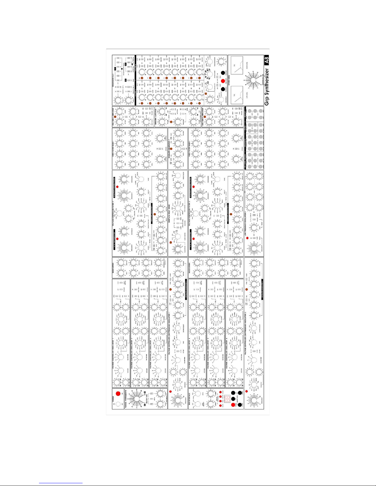
Grp Synthesizer A8 User’s Manual V. 2.06 2
Page 3

Grp Synthesizer A8 User’s Manual V. 2.06 3
CONTENTS
CONTENTS 3
FOREWORD 6
SOME WORDS OF WISDOM 6
Operating Conditions 6
Power Supply 6
Operation 6
Maintenance 6
Proper Use
SETUP AND CONNECTIONS 7
Contents 7
Connections 7
AC Connections 7
MIDI Connections 7
Audio Connections 7
Rear Panel Audio Connections 7
Front Panel Audio Connections 8
Analog CV/Gate Connections 8
OVERVIEW 9
WHAT IS INSIDE THE A8? 10
BASIC OPERATIONS 11
Powering the instrument 11
Tuning the instrument 11
Dealing with Modes and MIDI Interface 11
Note Priority 11
Mode Selection 12
Pitch Bend 12
MIDI Interface 12
CV Offset 13
FRONT PANEL CONNECTIONS 15
CV-Gate-Trigger 15
Sequencer 15
Filter 16
Main Out 16
REAR PANEL CONNECTIONS 17
Power 17
MIDI 17
Audio 17
Future Upgrades 17
A8 AUDIO AND MODULATION ROUTINGS 18
SOUND SOURCES AND SOUND MODIFIERS PATH 18
VOLTAGE CONTROLLED OSCILLATOR 1-6 19
Frequency Control 19
Page 4

Grp Synthesizer A8 User’s Manual V. 2.06 4
Waveform Control 20
The waveform 20
Output 21
VOLTAGE CONTROLLED OSCILLATOR 1-6 REFERENCE 22
RING MODULATOR 23
NOISE GENERATOR 23
NOISE GENERATOR REFERENCE 23
VOLTAGE CONTROLLED FILTER 1-2 24
VOLTAGE CONTROLLED FILTER 1-2 REFERENCE 25
Controls in common for both Filters 25
Controls for 24 dB/Oct transistor-ladder Low Pass Filter 25
Controls for 12 dB/Oct state-variable Filter 26
FIXED FILTER BANK 26
FIXED FILTER REFERENCE 26
VOLTAGE CONTROLLED AMPLIFIER 27
VOLTAGE CONTR AMPLIFIER REFERENCE 27
MAIN MIX / AUTO PAN 28
MAIN MIX / AUTO PAN REFERENCE 28
Controls for the Upper Section 28
Controls for the Lower Section 28
Controls for the Auto Pan Section 29
STEREO MAIN 29
A8 MODULATION SOURCES AND CONTROL MODIFIERS 30
Modulation Sources 31
Modulation Destinations
VOLTAGE CONTROLLED LOW FREQUENCY OSCILLATOR 1-2 33
Frequency Control 33
Waveform Control 33
Hard Sync 34
Output Offset 34
Shaping 34
VOLTAGE CONTROLLED LOW FREQUENCY OSCILLATOR 1-2 REFERENCE 35
Frequency Controls 35
Waveform Controls 35
Sync Controls 35
Shaping Controls 36
LOW FREQUENCY OSCILLATOR 3 36
Frequency and Frequency Range 36
Waveshape 36
Output Control 37
Modulation Routings 37
LOW FREQUENCY OSCILLATOR 3 REFERENCE 37
Frequency 37
Waveshape Controls 37
Output Controls 37
Destination Controls 37
ENVELOPE GENERATORS 38
Common behaviours and controls - Trigger Mode 38
Page 5

Grp Synthesizer A8 User’s Manual V. 2.06 5
Common behaviours and controls - Gate source select 39
Common behaviours - Envelope Structure 39
SIX STAGE ENVELOPE GENERATOR (ENV 1 / ENV 4) 39
SIX STAGE ENVELOPE GENERATOR (ENV 1 / ENV 4) REFERENCE 40
Envelope stages parameters 40
Gate (source) parameters 40
Trig switch parameters 40
Activity LED 41
SIX STAGE ENVELOPE GENERATOR (ENV 3 / ENV 6) 41
SIX STAGE ENVELOPE GENERATOR (ENV 3 / ENV 6) REFERENCE 41
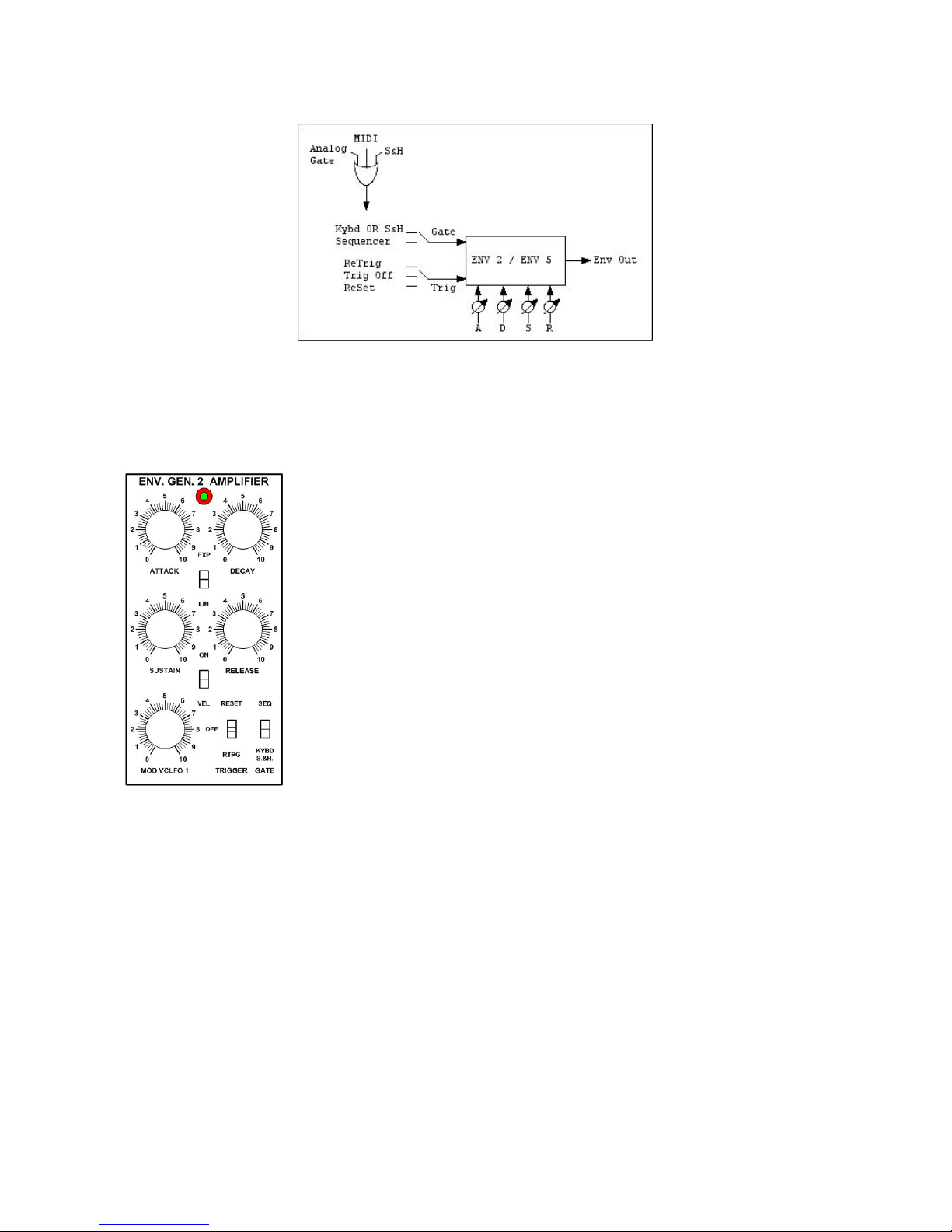
FOUR STAGE ENVELOPE GENERATOR (ENV 2 / ENV 5) 42
FOUR STAGE ENVELOPE GENERATOR (ENV 2 / ENV 5) REFERENCE 42
Envelope stages parameters 42
Gate (source) parameters 42
Trig switch parameters 42
Activity LED 43
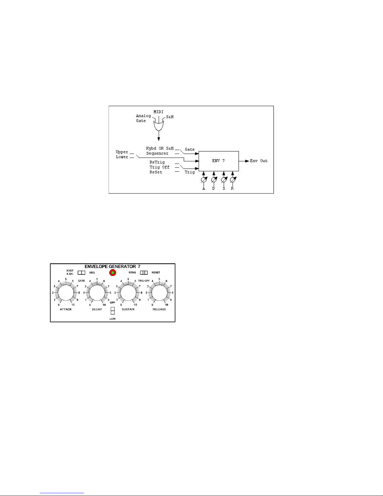
FOUR STAGE AUXILIARY ENVELOPE GENERATOR (ENV 7) 43
FOUR STAGE AUXILIARY ENVELOPE GENERATOR (ENV 7) REFERENCE 43
Envelope stage parameters 43
Gate (source) parameters 43
Trig switch parameters 44
Activity LED 44
Assign Switch 44
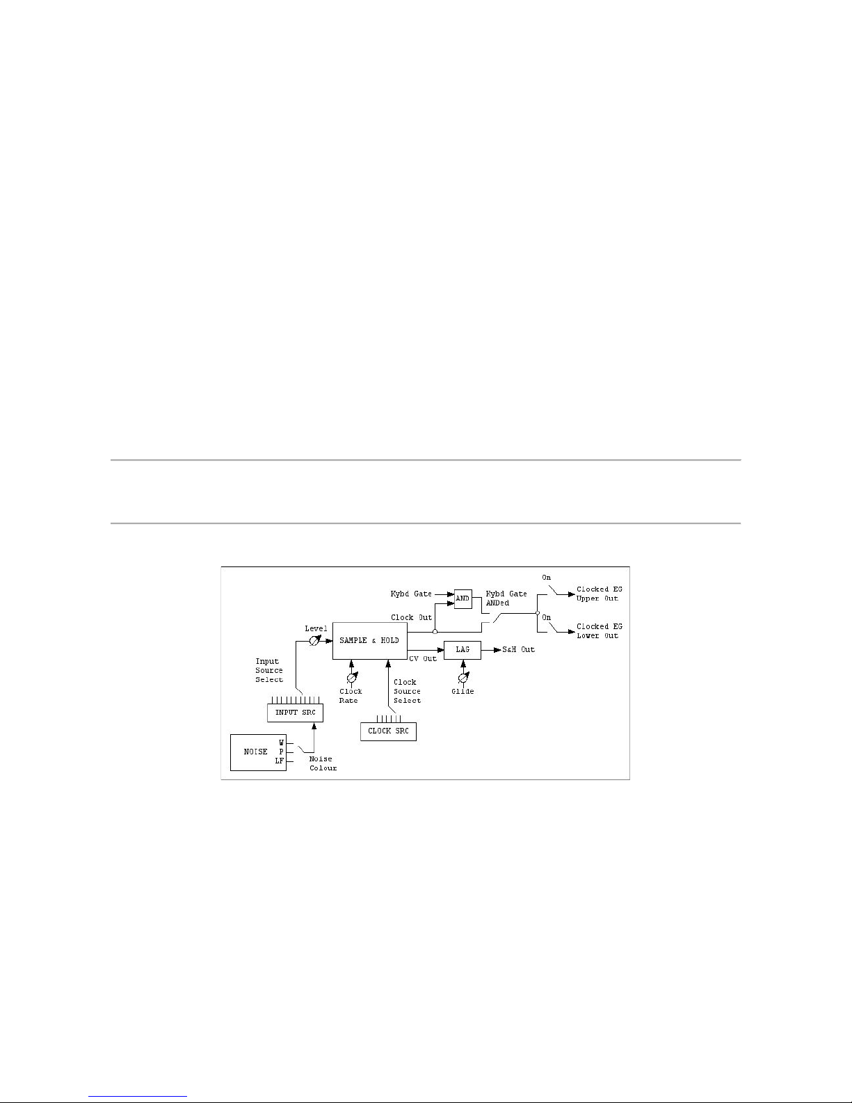
SAMPLE & HOLD / NOISE GENERATOR 44
Input Source Selection 45
Clock Source Selection 45
Glide 45
Clocked Envelope 45
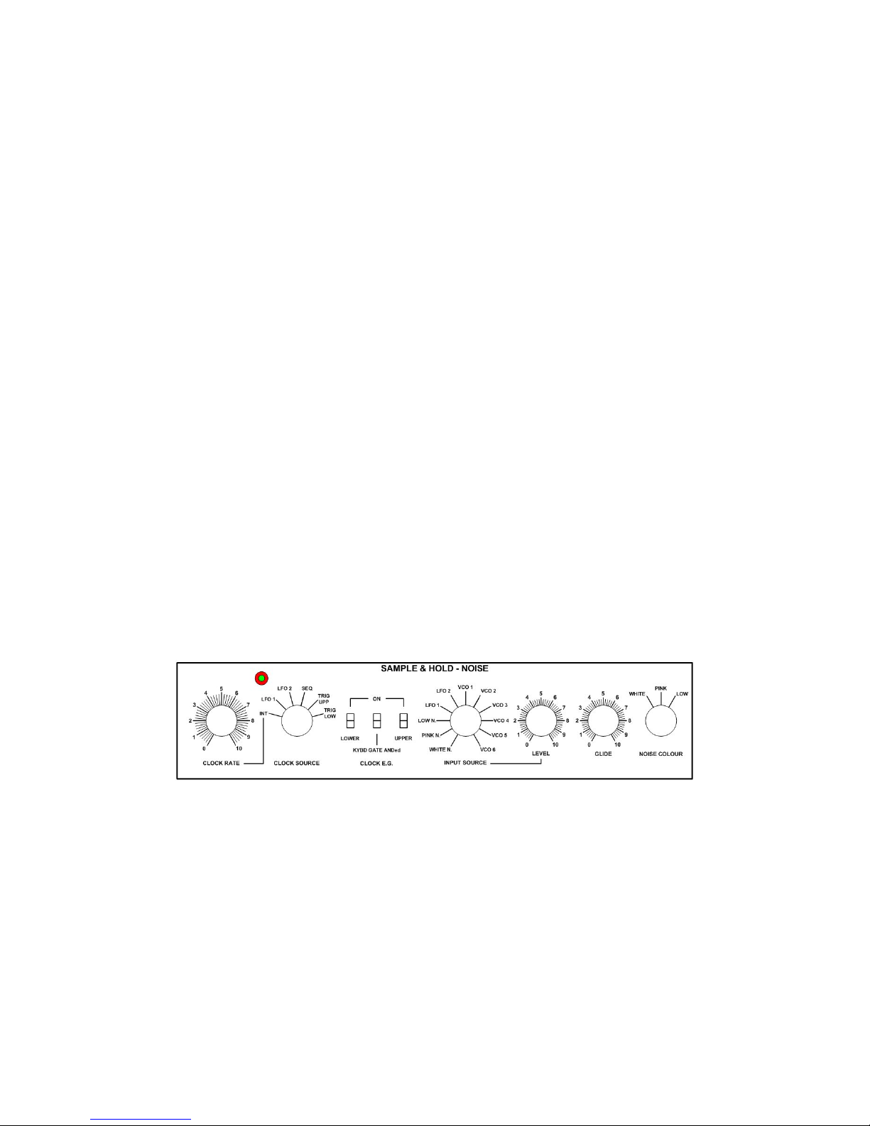
SAMPLE & HOLD / NOISE GENERATOR REFERENCE 45
Sample & Hold Controls 45
Noise Generator Controls 46
STEP SEQUENCER 47
Clock and Divider/Multiplier Parameters 47
Advance and Repetitions Parameters 47
Sequencer Mode Parameters 47
Column Parameters 48
Step Parameters 48
Assign Parameters 48
STEP SEQUENCER REFERENCE 49
Integration, Quantization, Range and Assign Section 49
VCO Sequencer Enable 49
PW SEQ ENA(ble) 50
F(i)LT(er) SEQ ENA(ble) 50
Column A Section - Column B Section 51
Clock & Clock Divider 51
Step Repeat & Loop 52
Sequencer mode 52
Manual controls 53
Sequencer remote connections and controls on the front panel 53
Page 6

Grp Synthesizer A8 User’s Manual V. 2.06 6
FOREWORD
Thank you for purchasing the Grp Synthesizer A8: this machine will rewards you with years of sonic
satisfactions and, to ensure your instrument will functions properly, please read this manual.
SOME WORDS OF WISDOM
Read the following safely tips carefully! You should always observe some basic precautions when
dealing with electronic equipment, for you safety and for safety of your own equipment.
Operating Conditions
• Never use the synthesizer under potentially damp/wet conditions such bathrooms, swimming
pools, etc.
• Do not use the instrument in extremely dusty and dirty environments.
• Do not place the instrument near heat sources like radiators.
• Do not expose the instrument to direct sunlight; the wooden cabinet is varnished with a
traditional and trusted procedure, but ultraviolet rays from sunlight can quickly fade the
original wooden colour.
• Do not expose the device to extreme vibrations.
• Save the original crate and boxing for future shipping of the instrument.
Power Supply
• Always check that the AC current in your area is correct for the instrument BEFORE turning it
on. The Grp Synthesizer A8 can be powered with 110-220 V 50-60 Hz, switchable in the rear
panel. Please, check and re-check.
• Unplug the device when you are not using it for longer periods.
• Never touch the plug with wet hands.
• When unplugging the instrument, always grab and pull the plug, never the cable.
Operation
• Although you are a rockstar, NEVER place cans of beer, coke, water (?) or other potentially
spilling liquids on or near the instrument.
• The Grp A8 Synthesizer is an heavy synthesizer: place it on a suitable solid surface or table.
• The Grp A8 Synthesizer can be very LOUD: please, be careful with the big volume knob on
the lower right of the front panel.
Maintenance
• Do not open the instrument; do not unscrew the front/rear panels. Inside the instrument,
there aren’t user’s serviciable parts.
Proper Use
• This synthesizer is designed exclusively to produce audio rate frequency signals for musical
purpose. Any other use is prohibited and voids the warranty extended by Grp Synthesizer.
Grp Synthesizer is non liable for damanges due to incorrect use.
Page 7
Grp Synthesizer A8 User’s Manual V. 2.06 7
SETUP AND CONNECTIONS
Contents
Your Grp Synthesizer A8 comes completed with:
• The instrument (pretty big, eh?) itself.
• The suitable power supply cable.
• This manual.
Ensure that all the items above listed were included. If something is missing, contact your local dealer.
As said above, we recommend that you carefully save the original packing material for future
transport/shipping.
Connections
In order to get started with your Grp Synthesizer A8, you will need some connections:
• Suitable AC powering. Make sure (twice) that the power available in your country matches
the correct position in voltage switch 110-220V on the rear panel.
• A MIDI Keyboard/Controller with proper MIDI cable. Those can be unnecessary if you plan to
use the synthesizer only with analog CV/Gate or with the internal Step Sequencer.
• A analog CV/Gate source, with a bunch of !” TS unbalanced cables.
AC Connections
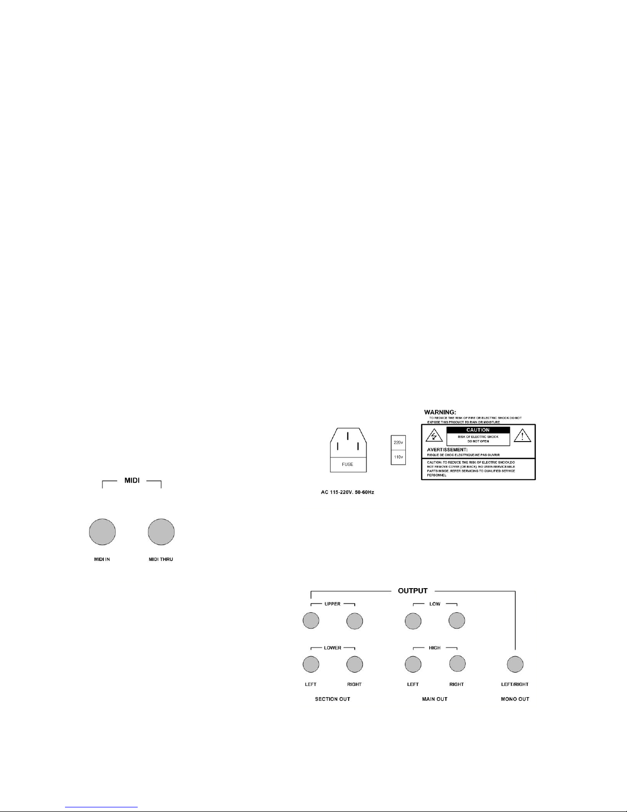
Without doubts, the only place to make
connection for AC cord is on the rear panel;
please. DO NOT detach the ground
connection.
MIDI Connections
Another easy issue:
the MIDI Port (with In and Thru) is located on the rear panel. While the Grp
Synthesizer A8 doesn’t emit any MIDI signal, it can receive MIDI messages
simoultaneously from up to two different sources connected to its MIDI Input.
The data received at Input connector are echoed back to MIDI Thru
connector.
Audio Connections
The things are more varied: you can choose
different connections, suited to different
needs, on both front and rear panel.
Rear Panel Audio Connections
If you’ll use the A8 in a fixed, studio
environment, is best to use the Rear panel
Audio Connections, otherwise, you’ll be free to use the more easy access to the front panel
connection (more on this, later). On the rear, you’ll find:
Page 8
Grp Synthesizer A8 User’s Manual V. 2.06 8
• SECTION OUT UPPER LEFT-RIGHT: separate stereo out for Upper part after Pan/AutoPan
module, but before the Main Out Volume.
• SECTION OUT LOWER LEFT-RIGHT: separate stereo out for the Lower part after
Pan/AutoPan module, but before the Main Out Volume.
• MAIN OUT LEFT-RIGHT LOW LEVEL: doubles the front panel main stereo output (this
output is at a quiet low level).
• MAIN OUT LEFT-RIGHT HIGH LEVEL: doubles the front panel main stereo output (be
careful: this output is at a fairly high level).
• LEFT+RIGHT MONO OUT: the sum of Upper and Lower Sections; the connection doubles
the front panel mono output.
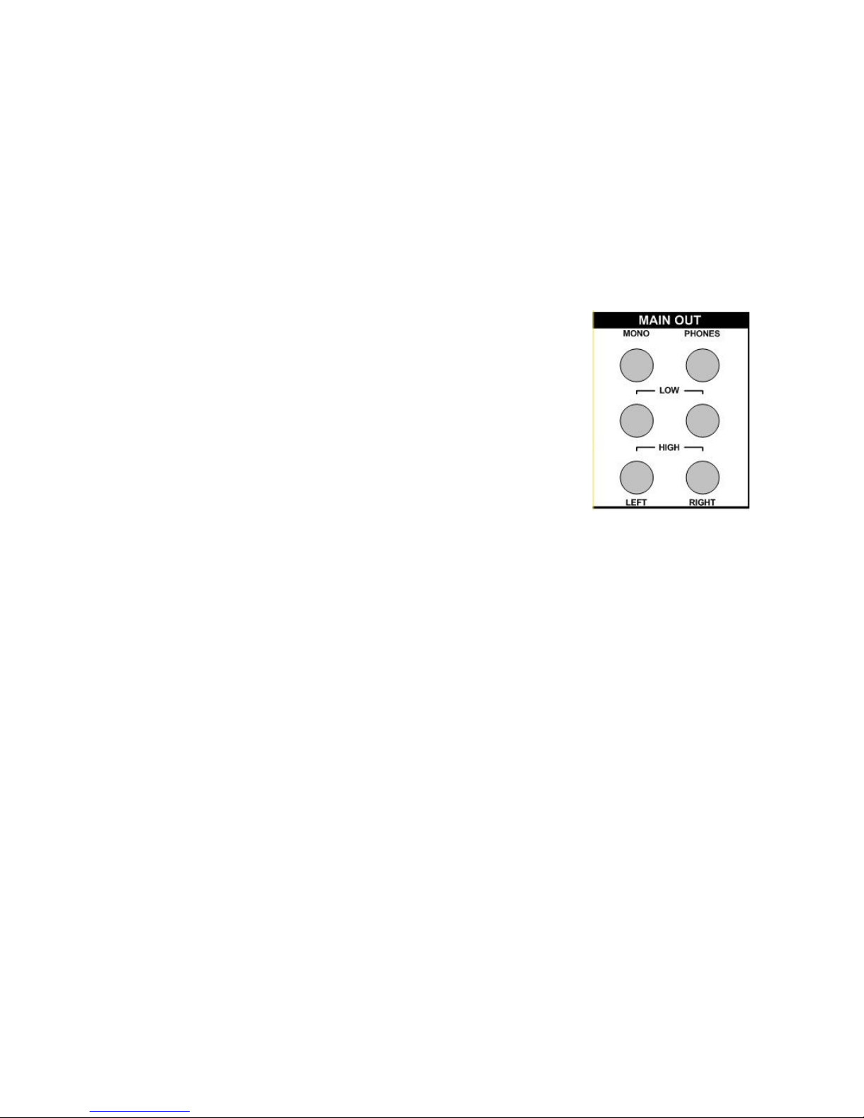
Front Panel Audio Connections
On the front panel, there are the following audio connections:
• MONO OUT: summed signal of Upper and Lower Sections (same
as Mono Out on the rear panel)
• PHONES: headphones stereo output.
• LEFT - RIGHT LOW LEVEL OUT: low impedance stereo output.
• LEFT - RIGHT HIGH LEVEL OUT: (fairly) high impedance stereo
output.
Analog CV/Gate Connections
If you dislike (or if you dont need) MIDI, you can rely on old school analog CV and Gate connections;
on the front panel you’ll find direct access to separate Upper and Lower Sections of the instrument
or, for a full scale control on a single couple of CV/Gate, the common Lower-Upper analog interface.
In details, there are connections for:
• LOWER SECTION Connections: Trig Input (0/+5V), Gate Input (0/+5V), CV Input (1V/Oct).
• UPPER SECTION Connections: as above.
• LOWER and UPPER Connections: as above, in common for both sections.
Page 9
Grp Synthesizer A8 User’s Manual V. 2.06 9
OVERVIEW
The Grp Synthesizer A8 is a complex, but not-so complex analog machine dual structure/bitimbral,
with an integrated Step Sequencer.
Each part (Upper or Lower section) is a complete and independent analog synthesizer fitted with
three VCOs each with separate SubOsc, one Ring Modulator, one Audio Mixer, two dynamic VCFs,
one Fixed Filter Bank, one VCA, three EGs, one LFO.
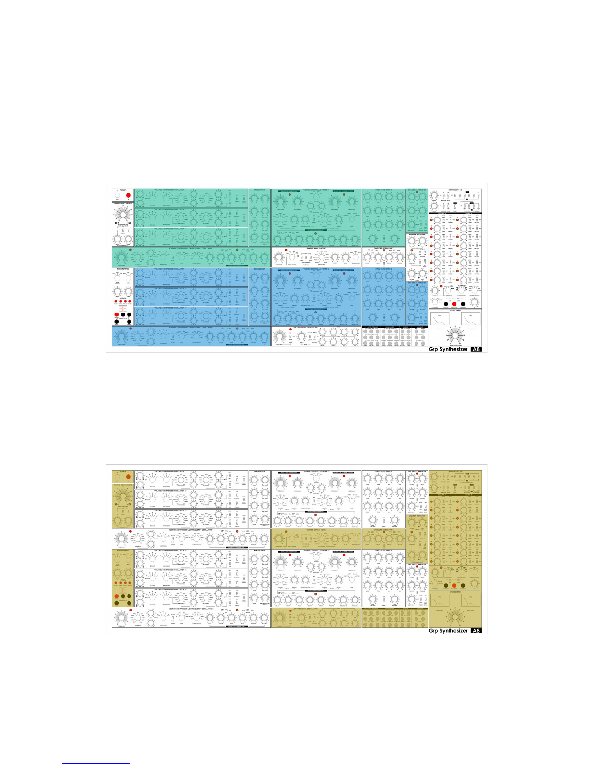
The above picture shows the modules concerning the Upper and Lower sections. As you can see,
they are disposed in a pretty simmetrical way on the front panel.
In addition, there is a group of common modules who can be shared by the two section or can
controls both sections simoultaneously; they are: Tuning-Portamento, MIDI Interface, Sample &
Hold/Noise Generator, Auxiliary Envelope Generator 7, Main Mix/Auto Pan, LFO 3, Main Volume,
Step Sequencer and Front Panel Connections.
The above picture shows the modules in common for both Upper and Lower sections of the
instrument.
Page 10
Grp Synthesizer A8 User’s Manual V. 2.06 10
WHAT’S INSIDE THE A8?
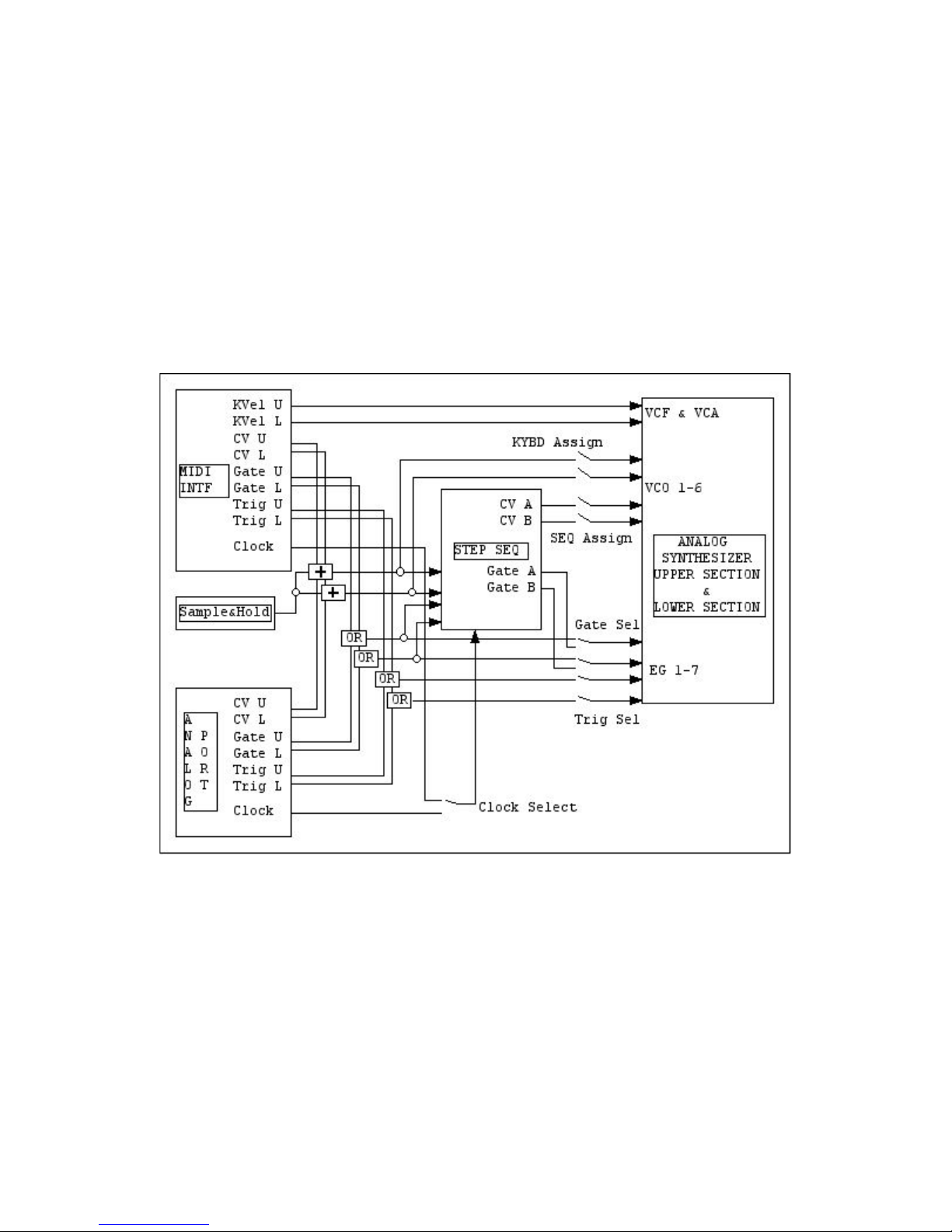
The whole instrument contains several different circuits:
• A MIDI INTERFACE who converts MIDI data in CV, Gate, Trigger, Key Velocity and Clock
data for Upper and Lower Sections.
• An ANALOG PORT who receives CV, Gate, Trigger, Clock for Upper and Lower Sections.
• A STEP SEQUENCER who drives VCO Freq & PWM, VCF Freq, EG Gate for Upper and
Lower Sections.
• A dual section ANALOG SYNTHESIZER able to create two entirely separate patches, or - at
request - work in cross audio rate modulation between VCOs on VCOs and VCOs on VCFs.
The above (simplified) picture shows the interactions between the different components of the A8.
Feel free to experiment with different sections of the synthesizer; first, with Upper/Lower synth parts,
then, with Step Sequencer.
Page 11
Grp Synthesizer A8 User’s Manual V. 2.06 11
BASIC OPERATIONS
Powering the instrument
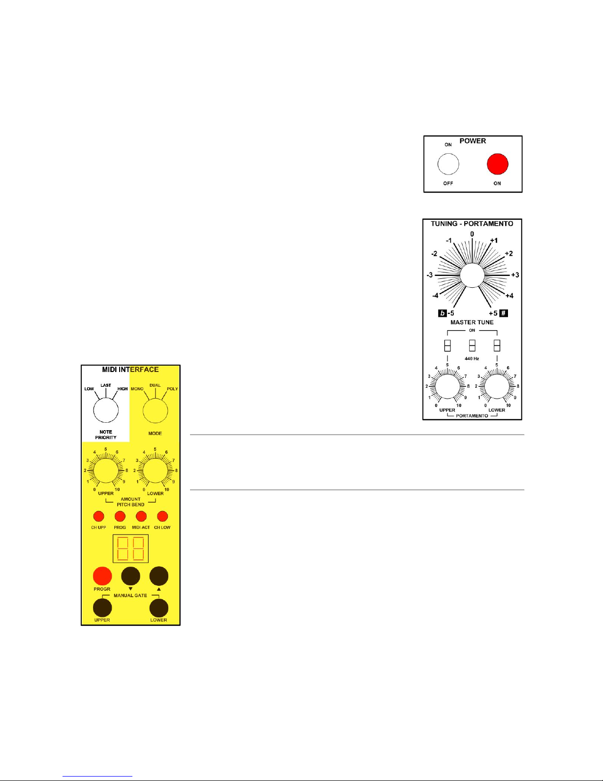
As you can easily imagine, this operation is done in the Power module on
left part of the front panel; the lamp goes red when the instrument is turned
on. Before turn on, please CHECK THE CORRECT AC RATING.
Tuning the instrument
The Grp A8 is an analog synthesizer but, despite this, the VCOs inside stays
in tune pretty well. For tuning the instrument to concert pitch, you should
work in the Tuning-Portamento module on the left part of the front panel.
With the Master Tune control, you can adjust the main tuning of the entire
instrument in a range of -7/+5 semitones; for a quick reference, you can
switch on the dedicated A-440 oscillator.
In the same module, there are the two Portamento Time Upper and Lower
(max time 2 seconds per octave) and Portamento On.
Dealing with Modes and MIDI Interface
In this module you’ll find all the settings related to
Note Priority, Voice Assign Modes, Pitch Bend
Amount and - obviously - MIDI Interface.
Note
As you can imagine, the external analog controls connected at the CV, Gate & Trigger
ports are not influenced by the settings of the Note Priority & Mode sections of the MIDI
Interface.
Note Priority
The Grp A8 offers three different Note Priority modes:
• In LOW Note, if the musician press more than a key, the instrument
will plays the lowest note .
• In LAST Note, the instrument will play the last note executed.
• In HIGH Note, the instrument will play the highest note.
Page 12
Grp Synthesizer A8 User’s Manual V. 2.06 12
Mode Selection
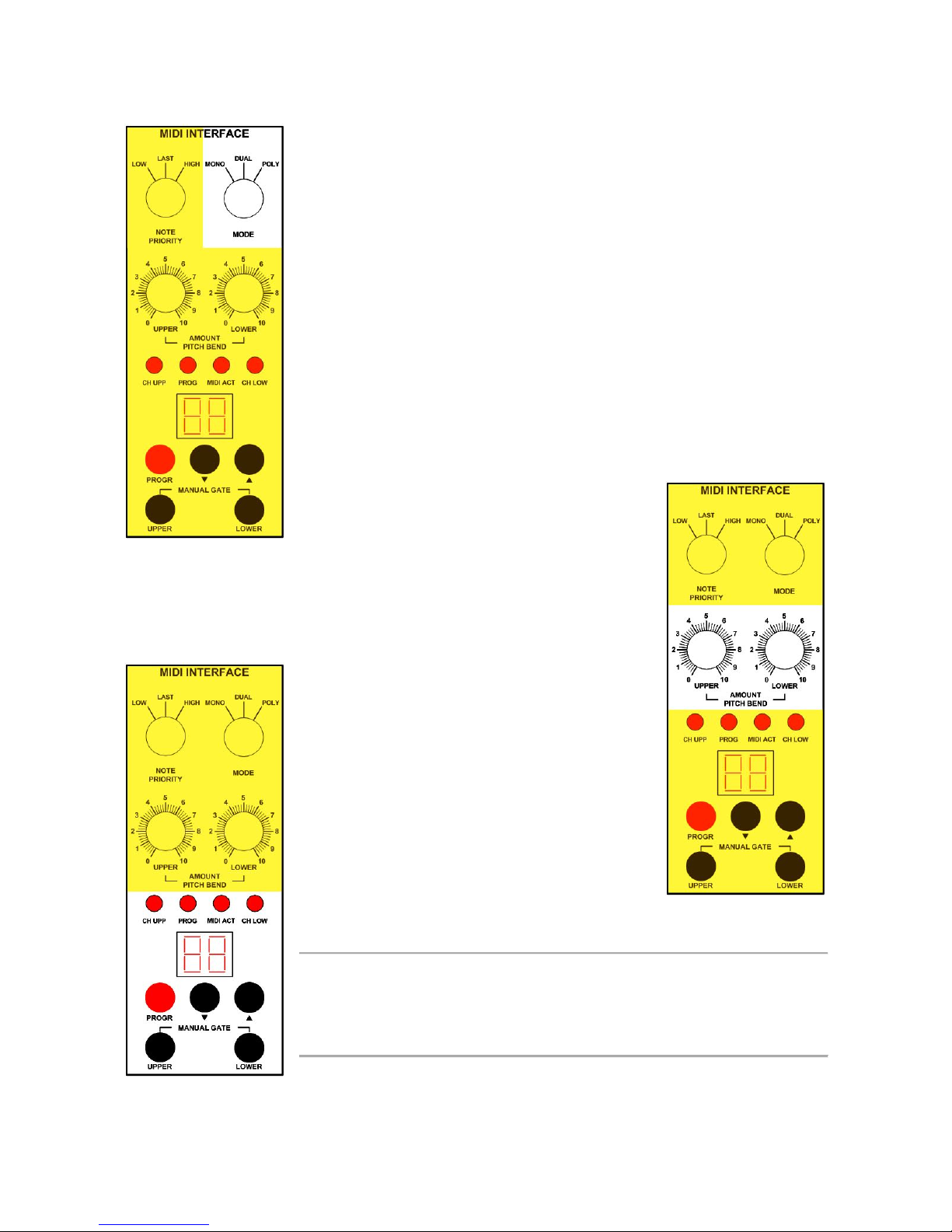
With the MODE Selector, you can choose between three different
behaviours:
• MONO: Upper and Lower sections works on the same MIDI
Channel previously set from the user (see below); all six oscillators,
four filters, amplifiers and modules plays together forming a single big
instrument.
• DUAL: the synthesizer works as a two-voice single instrument on
the same MIDI Channel for Upper and Lower parts. When one key
is pressed, you’ll have both Upper and Lower sections playing the
same note. When you press two key simoultaneously, you’ll get high
note played from Upper synth section and low note played from
Lower synth section.
• POLY: the sinthesizer works on two separate and independent
user’s definable MIDI Channel, one for Upper and the other for
Lower part (see below).
Pitch Bend
The two PITCH BEND AMOUNT controls (UPPER and LOWER) allow
the exact setting of the frequency deviation from the nominal pitch; the
maximum range equals +/-12 semitones.
MIDI Interface
With this part of the module, you can set the MIDI
Channel(s) with the two Increase/Decrease
pushbuttons (see below). The MIDI Interface
manages the following messages:
• Note On/Off w. Key Velocity
• Pitch Bend
• Modulation Wheel
• Channel Aftertouch
• Expression & Volume Pedal
• Damper Pedal
• Clock
Note
You can choose between the standard MIDI Channels 1-16 and seventeenth position
corresponding to OFF; in the latter setting, you’ll disconnect the MIDI data from reach the
Upper or Lower synth section, leaving them at only disposal of the analog CV-Gate-Trig
Interface on the front panel.
As we’ll see later, the MIDI Interface reacts to Start, Stop and Continue RealTime Commands: those
will be routed to the internal Step Sequencer for normal transport functions.
Page 13

Grp Synthesizer A8 User’s Manual V. 2.06 13
In the MIDI Interface, there are four LEDs:
• CH UPP LED: lighted in MONO and DUAL MODE, shows that the dual digit number
displayed is the MIDI Channel for the Upper synth section of the instrument.
• CH LOW LED: lighted in MONO and DUAL MODE, shows points that the dual number
displayed is the MIDI Channel for the Lower synth section of the instrument.
• PROG LED: turns on when you press the red PROG pushbutton in the MIDI Interface. When
lit, you are able to superimpose an octave(s) CV offset for the 3 Upper and 3 Lower VCOs.
More commands will be added in the future, with firmware updates (thru Host multiport on
rear panel).
• MIDI ACT(IVITY) LED: turns on if the synthesizer receive any MIDI message.
The available controls act as:
• MANUAL GATE UPPER: this button act as a Gate source for all the envelope generators
available (or assigned, as for the Aux EG 7) in the Upper synth section.
• MANUAL GATE LOWER: this button act as a Gate source for all the envelope generators
available (or assigned, as for the Aux EG 7) in the Lower synth section.
• INCREASE Button: will step forward the numeric value on the display.
• DECREASE Button: will step backward the numeric value on the display.
• PROGR BUTTON:
o If the instrument is set in MONO MODE (see above), the button enters the
Programmable Mode for the MIDI Interface (for load firmware upgrades thru HOST
port on rear panel).
o If the instrument is set in DUAL MODE, the button has the same function as above.
o If the instrument is set in POLY MODE, each pression on the pushbutton will loop
cycle on the numeric display one of the following options:
• MIDI CH UPP [the corresponding LED will light],
• MIDI CH LOW [the corresponding LED will light],
• PROGR MODE [the corresponding LED will light].
o In CH UPP and CH LOW MODE, you’ll set the desired MIDI Channel with the two
Increase/Decrease buttons. (Range 1-16, Off).
o In MONO or DUAL Mode, pressing repeately the PROG button, will cycle thru one
of the following options:
• CV Offset (see below),
• Upper plus (see note below) Lower MIDI Channel select options (01-16, Off).
Note
The value you select will be applied simoultaneously for both Parts; as wrote before, if you choose “Of(f)”, the selected
Part of the instrument will be left under full control of the analog control connections.
o In POLY Mode, you gain separate access to Upper and/or Lower MIDI Channel
adjust; the corresponding LED will turn on.
CV Offset
It is possible to add an octave offset on the CV received at the analog control inputs; in this way, you
can match the octave played by A8 with the range of your external analog controller.
Page 14

Grp Synthesizer A8 User’s Manual V. 2.06 14
One more pressing on the PROG button will enter the synthesizer’s MIDI Interface in CV Offset
Mode; Upper and Lower Parts can be offset in 1 octave increment on a range of 5 available octaves.
In the numeric display, you’ll read:
• U1/U5 (the default value is U3).
• L1/L5 (the default value is L3).
Note
As a rule of thumb, with VCOs Octave on 8’, if you want to hear in the real octave of your external analog controller, you
should select an Offset value of 3 (remember that the parameter range is 1-5). So, if you want to hear A3 = 440 Hz, put
your VCOs on 8’ and impart a CV Offset with value U3 and/or L3. If you impart a CV Offset with value U2/L2, you’ll play
a lower octave (e.g.: like if you have selected 16’ on VCOs). If you impart value U4/L4, you’ll play a higher octave (like if
you have selected 4’ on VCOs).
Page 15
Grp Synthesizer A8 User’s Manual V. 2.06 15
FRONT PANEL CONNECTIONS
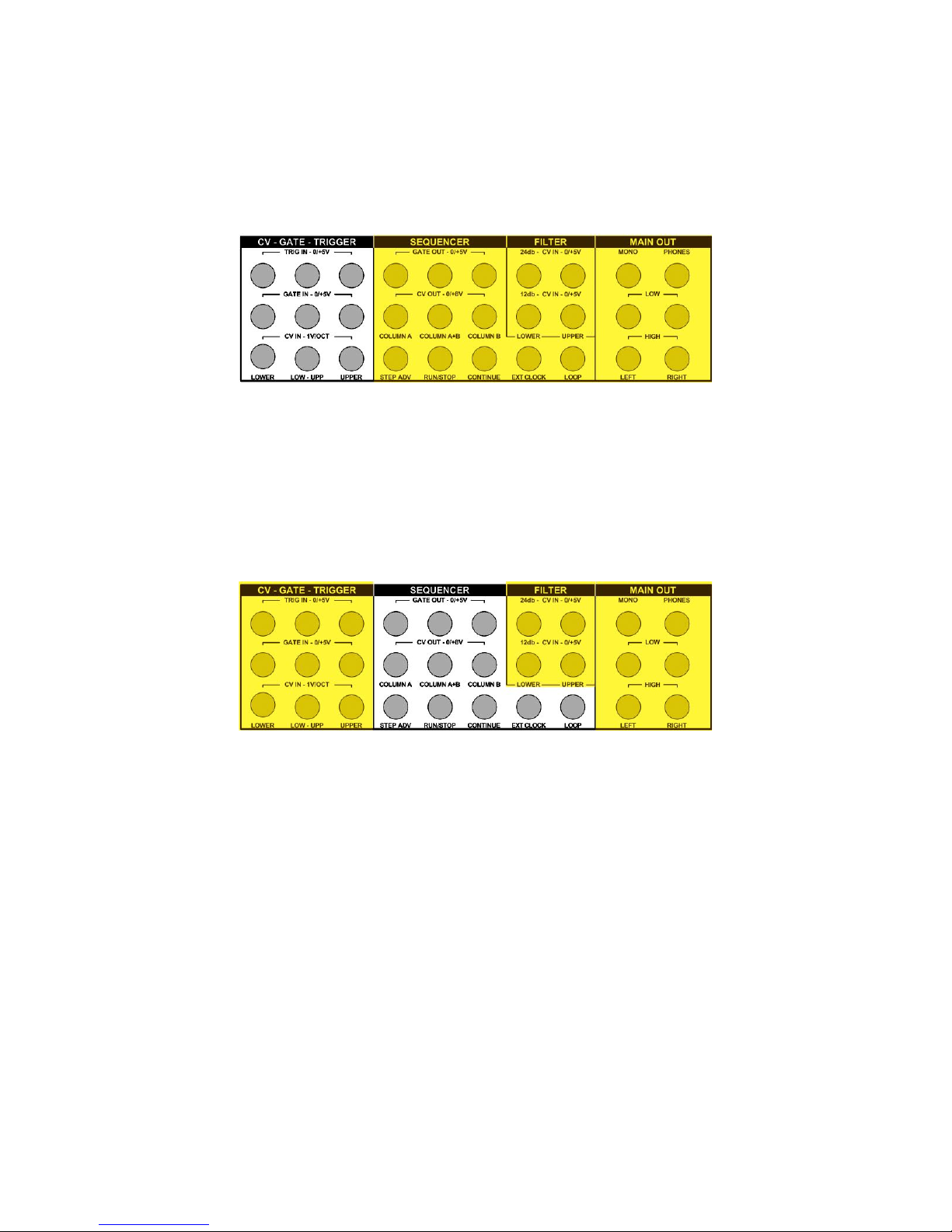
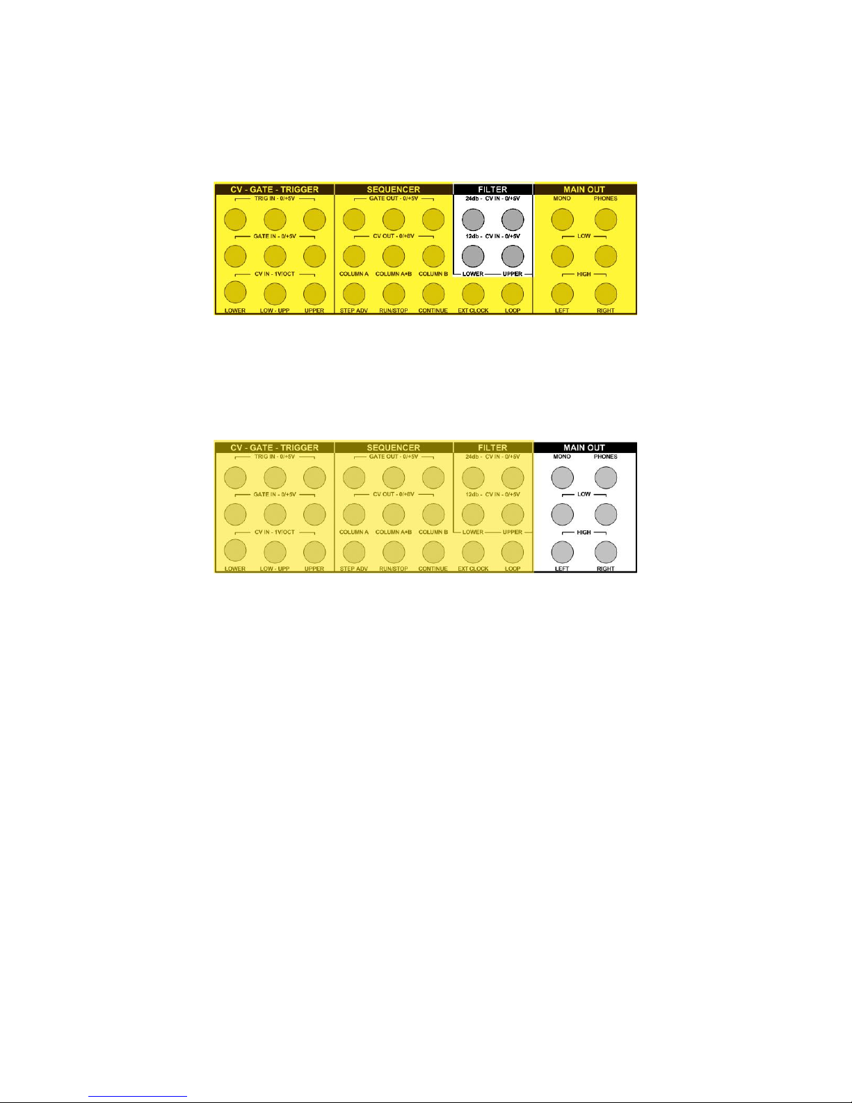
On the front panel, the available connections are organized in four separate blocks related to: CVGate-Trigger, Sequencer, Filter, Main Out.
CV-Gate-Trigger
This block of nine connectors is for the analog control of Lower section, Upper section, Lower &
Upper section; for control simoultaneously the two parts, you should connect external sources to the
central column of connections marked LOW-UPP. You can choose between:
• TRIG IN LOWER - LOW/UPP - UPPER: Analog Trig In 0/+5V
• GATE IN LOWER - LOW/UPP - UPPER: Analog Gate In 0/+5V)
• CV IN LOWER - LOW/UPP - UPPER: Analog CV In 1V/Oct.
Sequencer
Here are the connections for the Step Sequencer outputs and its external controls:
• GATE OUT COLUMN A - COLUMN A+B - COLUMN B: the Gate Output for the single
Column A or B and for the two Columns A+B combined in series (16x1 steps). Range:
0/+5V.
• CV OUT COLUMN A - COLUMN A+B - COLUMN B: the CV Out for the separate
Column A or B (8x2 steps) and for the two Columns combined in series. Range: 0/+8V.
• STEP ADVANCE: on each pulse (0/+5V) received at this port, the Step Sequencer advance
one step.
• RUN/STOP: each pulse (0/+5V) received will alternate between Run and Stop. This external
input will interact with the front panel control RUN/STOP. The Step Sequencer will restart
from step no. 1.
• CONTINUE: the pulse (0/+5V) received at this port will put the Sequencer in playback from
the last step played without resetting to step no. 1.
• EXT CLOCK: a train of pulse (0/+5V) received at this port will advance the Step Sequencer; it
will function only if the Step Sequencer is set to EXTERNAL CLOCK SELECT position.
Page 16
Grp Synthesizer A8 User’s Manual V. 2.06 16
• LOOP: the switching closure received on this port will enable the LOOP ON MODE for Step
Sequencer. This external input is parallel with the hardware LOOP SWITCH on the front
panel. If you want to remotely control LOOP ON, don’t forget to turn off its hardware switch
on the front panel).
Filter
• 24dB CV IN LOWER: external frequency control (0/+5v) for the Lower Low Pass Filter.
• 24 dB CV IN UPPER: external frequency control (0/+5V) for the Upper Low Pass Filter.
• 12 dB CV IN LOWER: external frequency control (0/+5V) for the Lower State-Variable Filter.
• 12 dB CV IN UPPER: external freqyency control (0/+5V) for the Upper State-Variable Filter.
Main Out
• MONO OUT: summed signal of Upper and Lower Part.
• PHONES: headphones stereo output.
• LEFT - RIGHT LOW LEVEL OUT: low impedance stereo output.
• LEFT - RIGHT HIGH LEVEL OUT: high impedance stereo output.
Page 17
Grp Synthesizer A8 User’s Manual V. 2.06 17
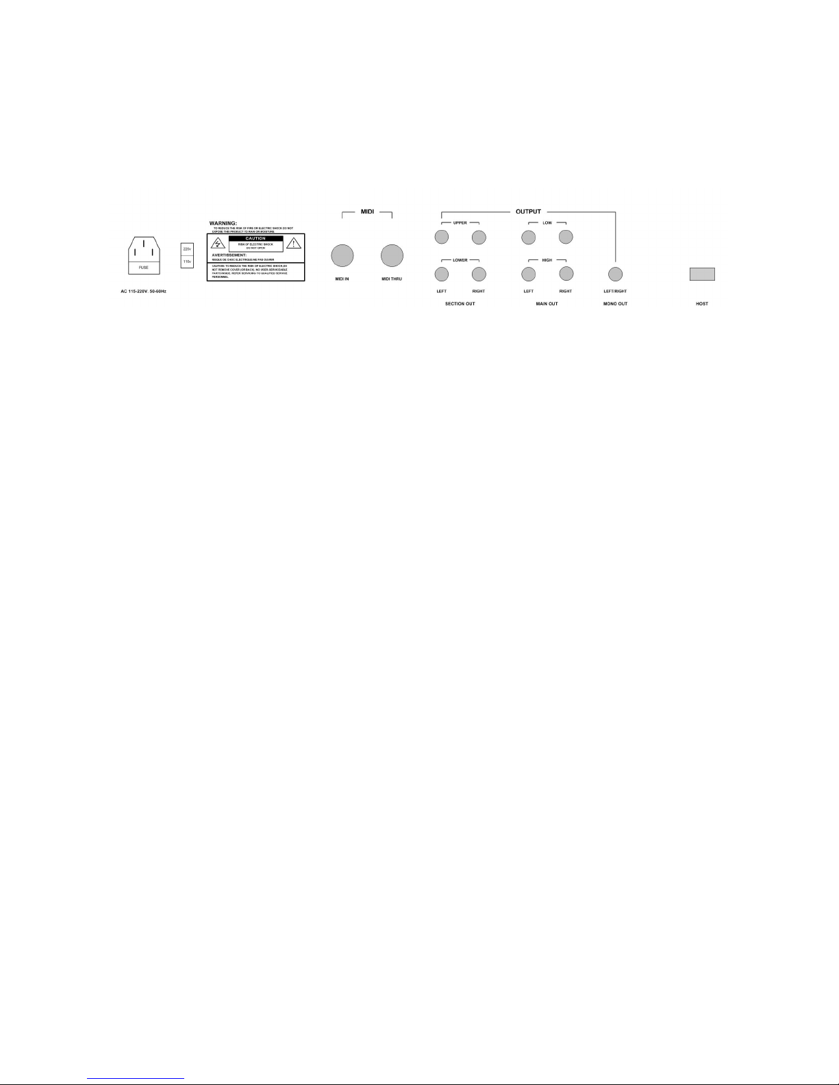
REAR PANEL CONNECTIONS
On the rear panel, you’ll find the connection related to:
Power
• AC RECEPTACLE
Midi
• MIDI IN
• MIDI THRU
Audio
• SECTION OUT UPPER LEFT-RIGHT: separate stereo out for Upper part after Pan/AutoPan
module, but before the Main Out Volume.
• SECTION OUT LOWER LEFT-RIGHT: separate stereo out for the Lower part after
Pan/AutoPan module, but before the Main Out Volume.
• MAIN OUT LEFT-RIGHT LOW LEVEL: doubles the front panel main stereo output (low
level).
• MAIN OUT LEFT-RIGHT HIGH LEVEL: doubles the front panel main stereo output (high
level).
• LEFT+RIGHT MONO OUT: doubles the front panel mono output.
Future upgrades
• HOST: this port is for future upgrades to the internal MIDI Interface firmware. At this very
moment, it is disabled.
Page 18
Grp Synthesizer A8 User’s Manual V. 2.06 18
A8 AUDIO AND MODULATION ROUTINGS
We’ll start from audio signal path (sources and modifiers): from oscillators thru the filters, till the
amplifier. Then, we’ll follow the modulation sources and their applications on the audio circuit.
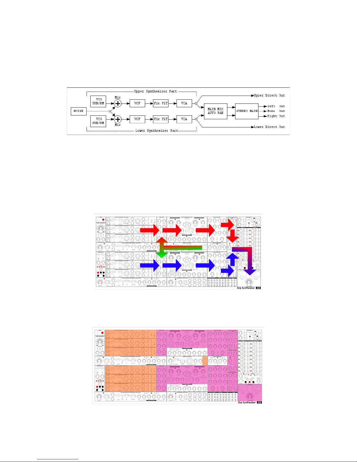
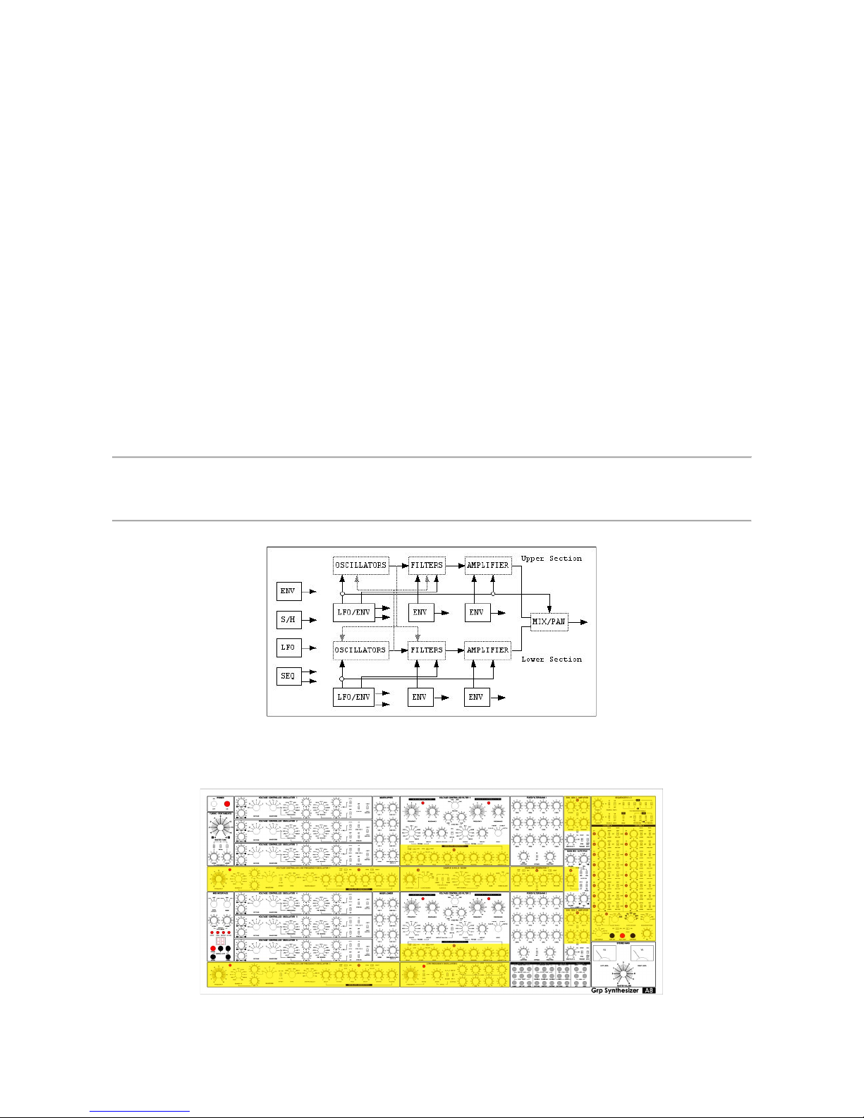
SOUND SOURCES AND SOUND MODIFIERS PATH
The above scheme is an over simplified view of the audio path for both Upper and Lower A8
Sections. As you can see, the signal produced from VCOs, SubOSCs, Noise Generator (in common
for both sections) and Ring Modulators is treated thru the dual VCF section and then equalized with
the Fixed Filter Bank; finally, the signal is amplified in the VCA and outputted thru the direct
connection on the rear panel. Both Upper and Lower signals goes into the Main Mix / Auto Pan and
the Stereo Main section.
Above, you can track the Upper and Lower audio signal path on the synthesizer’s front panel.
Below, the front panel with the highlighted positioning of the Sound Sources and the Sound Modifiers.
Following, we’ll give explanations of the single audio source/modifier sections.
Page 19
Grp Synthesizer A8 User’s Manual V. 2.06 19
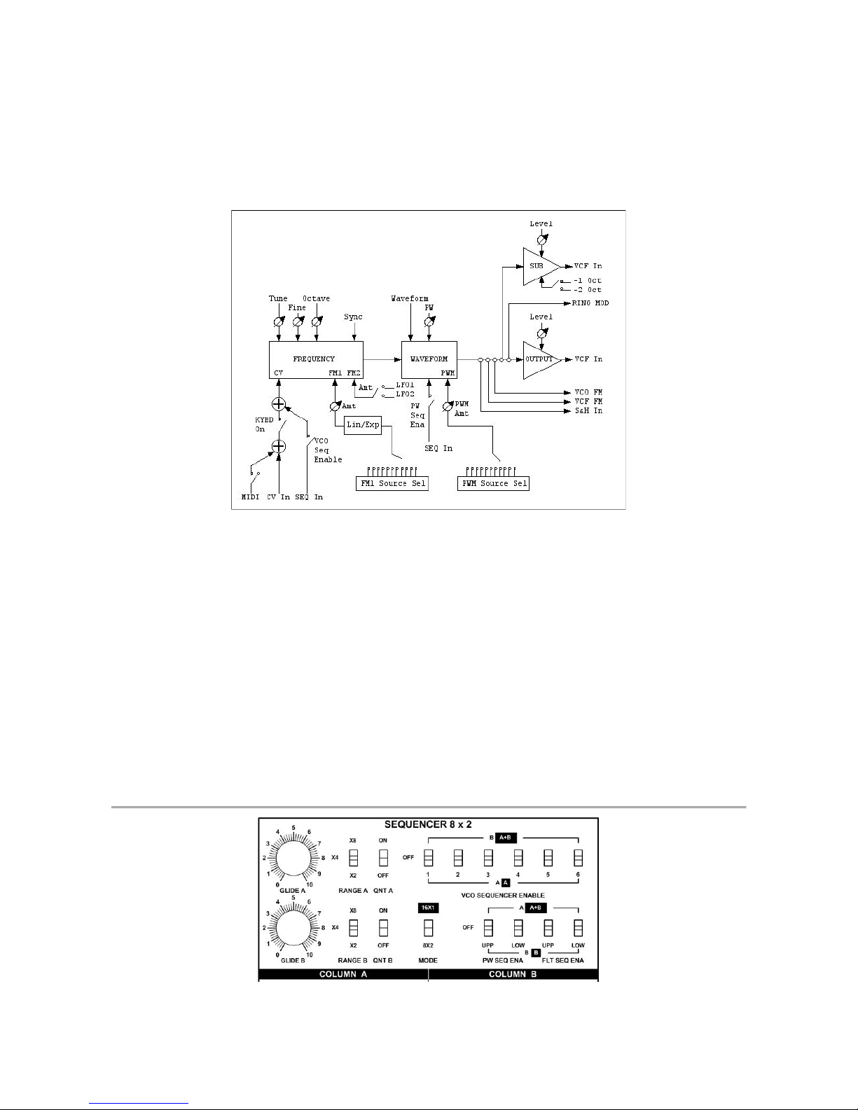
VOLTAGE CONTROLLED OSCILLATOR 1-6
The six VCOs comprised in A8 Synthesizer are, more or less, all equal; minor differencies are found in
the FM/PWM Sources and Hard Sync capability.
The VCO behaviours are organized in three main stages: Frequency Control and Frequency
Modulations, Waveform Selection and Pulse Width Modulation, Output Leveling and Suboscillation.
Frequency Control
The nominal Frequency of the VCO is defined with three dedicated controls on the front panel:
Octave Selector, Tune Pot and Fine Tune Pot. In addition, is possible to put the VCO under control
of any combinations of three external CV Sources: MIDI Interface, CV In (analog ports on the front
panel), Step Sequencer.
As we’ll see later, those three sources interact each other, for (e.g.) real-time transpose of the
sequencer or whatever. Is it possibile to detach the realtime Keyboard Control from the VCOs
Frequency; in this way, both the MIDI Note On conversion and the external CV In data are
disconnected from the selected oscillator; the Step Sequencer remains only external frequency
control available, free from unnecessary real-time transposition, but you’ll be forced to raise the
footage of VCOs for re-gain the correct playing range.
Page 20
Grp Synthesizer A8 User’s Manual V. 2.06 20
Note
Once you’ll turn on the Oscillator Sequencer Enable switch (in Step Sequencer section), the Step Sequencer CV is always
connected to the oscillator nominal frequency; so, the only way for prepatch VCOs under Step Sequencer control and
not have undesired transposition is to put at zero the Step Value (zero means in full counterclockwise motion).
The VCO has two FM busses: FM 1 buss has a Linear/Exponential selector and a huge amount of
possible FM sources (low rate for cyclic modulation or audio rate for harmonic control). With audiorate modulation in Exponential mode, the perceived intonation drifts from nominal value; with audiorate modulation in Linear mode, the perceived intonation (for an ample modulation index) remains
stable. FM 2 buss works only in Exponential mode and can be connected with LFO 1 or 2; while this
kind of circuit can be found useful mainly for vibratos, don’t forget that in A8 Synthesizer, the LFOs
goes fairly high in the audio range.
As above, the Hard Sync capability can be useful not only for rock-steady tune, but for generating
more harmonic peaks in the slave oscillator.
Waveform Control
The waveform of the VCO can be selected with a dedicate multiposition switch; you can choose
between the typical analog waveshapes, plus the combination of Sawtooth and variable Pulse.
The Pulse Width Modulation can be controlled in nominal position, for the “starting point” in the
Symmetry value, and can be assigned as destination for a huge amount of possible modulation
sources. In addition, it is possibile to route straightly the output of the Step Sequencer CV (Row A or
Row B) to drive the PWM.
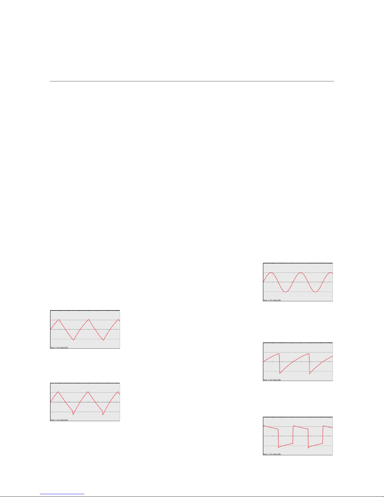
The waveforms
As you expect, the VCOs in A8 Synthesizer are full analog; so, the
waveforms available are pretty standardized in the analog heritage:
Sine Wave: full energy on the fundamental frequency, no higher
harmonics.
Triangle Wave: odd harmonics only, with energy decaying in exponential
shape.
Sawtooth Wave: even and odd harmonics, with energy decaying in linear
shape.
Triangle + Sawtooth: mix of the previous two waves.
Square/Pulse Wave: odd harmonics only, with linear decaying energy,
when the duty cycle (a.k.a. symmetry, a.k.a. pulse width) is at 50%.
Page 21
Grp Synthesizer A8 User’s Manual V. 2.06 21
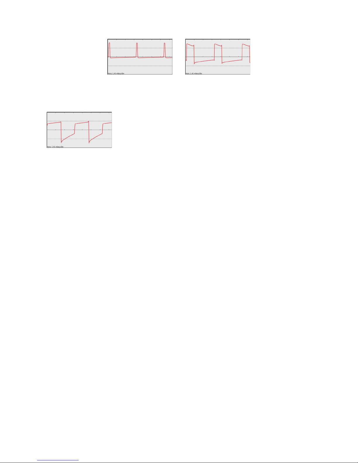
When the duty cycle goes on different ratio, the harmonic content will loose the harmonics multiples
of the numeric ratio (e.g.; a Pulse Wave at 30% has harmonics 1, 2, 4, 5, 7, 8, 10, 11, 13, 14…). Upper
left pictcure shows a 10% Pulse Wave; upper right shows a 75% Pulse Wave.
Square + Sawtooth: mix of the previous two waves. The Square
component can be PW modulated as usual.
Output
The signal outputted from VCO goes straight into the Filter(s) Section; is it possibile to control the
amount of signal with the dedicated Level potentiometer. The signal form VCO, before Level
regulation, is routed to a dedicated frequency divider, for Suboscillation -1 Octave (original Frequency
/2) or -2 Octaves (original Frequency /4).
Each VCO has his own indipendent Suboscillator; the signal subdivided is always a Square Wave, with
no respect for the original waveform generated.
The signals from VCOs 2 and 3, 5 and 6 are respectively routed to Upper and Lower Ring
Modulators; in this case, the waveform selection (and Frequency ratio) can severely alter the final
result.
Finally, the full range (audio and low freq) signal form the VCO can be routed to the others VCO FM
Input (for audio rate/low freq linear/exponential frequency modulation), to theFilter(s) Cutoff (for the
audio rate/low freq exponential frequency modulation) and to the common Sample & Hold section
(like the other possibile S&H sources).
Page 22
Grp Synthesizer A8 User’s Manual V. 2.06 22
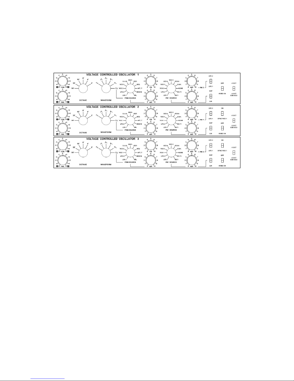
VOLTAGE CONTROLLED OSCILLATOR 1-6 REFERENCE
As stated above, there are few minor differencies between VCOs, but the core functions are the
same.
Following here, we’ll give description of every available control.
• TUNE: Coarse Tune Control; operating range: +/- one octave.
• FINE: Fine Tune Control; operating range: +/- 1 tone.
• OCTAVE: Selection of the playing octave; operating range: 64’-2’.
• SYNC: Enable Hard Sync for the slave VCOs (2 and 3, 5 and 6); operating range: On/Off.
• KYBD: Detach the keyboard CV (thru MIDI Interface or CV/Gate Interface) from the control
of VCO; operating range: On/Off.
• FM 1 SOURCE: Selection of the modulating source for PW; operating range (in full option):
LFO 1, LFO 2, VCO 1, VCO 2, VCO 3, VCO 4, VCO 5, VCO 6, S&H, NOISE, EG7+
(positive going only), EG7- (negative-going only).
• AMT: The Frequency Modulation 1 buss Amount; operating range 0-10.
• LIN/EXP: Selection for FM behaviour; operating range: Linear/Exponential.
• FM 2 AMT: the Frequency Modulation 2 buss Amout; operating range: 0-10.
• FM 2 LFO 1/LFO 2: Selection for the modulating source; operating range: LFO 1/LFO 2. As
said above, FM 2 buss follows always exponential mode.
• WAVEFORM: Selection of the desired audio shape; operating range: Sine, Triangle,
Triangle+Sawtooth, Sawtooth, Sawtooth+Pulse, Pulse.
• PW: Nominal value for Pulse Simmetry; operating range 50-100%. At 100, you’ll get silence.
• PWM Source: The possibile Pulse Width Modulation source; the sources slightly differs from
VCO to VCO; operating range (in full option): LFO 1, LFO 2, VCO 1, VCO 2, VCO 3, VCO
4, VCO 5, VCO 6, S&H, EG7+ (positive-going only), EG7- (negative-going only), SEQ,
AFTERTOUCH, MODULATION WHEEL, Key VELOCITY.
• AMT: The Pulse Width Modulation Amount from the selected source; operating range 0-10.
• SUB VCO: Selection for frequency dividing factor; operating range: -1 OCT/-2 OCT.
Page 23

Grp Synthesizer A8 User’s Manual V. 2.06 23
The VCO Level and VCO SUB Osc Level are located into the rightmost MIXER module (Upper and
Lower for VCOs1-2-3 and 4-5-6).
RING MODULATOR
Each section of A8 has a separate Ring Modulator module; the Upper Ring
Mod treats the waveforms selected in VCOs 2 and 3, prior Level
attenuation; the Lower Ring Mod treats the waveforms selected in VCOs 5
and 6.
Ring Modulation performs sum and subtraction for each harmonic frequency
present in the two signals at the input of the circuit: if signal “a” (e.g.; VCO 2) is a single sine wave at
100 Hz and signal “b” (e.g.; VCO 3) is a single sine wave at 500 Hz, the outputted result of Ring
Modulation is: 100 + 500 = 600 Hz plus 100 - 500 = -400 Hz (the minus sign means phase
inversion); if the two input signals contains more than a single sine wave, the sums and subtractions
are performed for each couple of harmonic frequencies available. So, two sawtooth waves ring
modulated leads to a dense harmonic result.
If one of the two VCOs ring modulated is slowly modulated (from an LFO or from a Envelope
Generator), the Ring Mod result will be fairly clangorous.
Each Ring Modulator has only one panel control regarding its output Level; this control is located, as
usual, in the Upper/Lower MIXER.
NOISE GENERATOR
There is only one Noise Generator that works in both Upper
and Lower sections of A8 Synthesizer. It acts mainly in two
roles: as sound source (winds, surfs and similar) available into
the audio MIXER Upper/Lower, as modulation source for
VCO/VCF FM and as sampling source for the SAMPLE &
HOLD module.
While each Upper and Lower MIXER has a separate NOISE Level control (as seen two
pictures before), the colour noise will be the same in both parts of A8 Synthesizer. You
can choose the type of noise (Low Frequency, Pink, White Noise) with the Noise
Colour control located into the SAMPLE & HOLD module.
NOISE GENERATOR REFERENCE
As above, the two controls concerning the Noise Generator are distributed on the whole front panel
of A8 Synthesizer:
• NOISE Level: each MIXER (Upper and Lower) has separate volume control for the same
Noise Generator; operating range: 0-10.
• NOISE COLOUR: available in the S&H module, it allows the choice between three different
noise types; operating range: White (equal power per unit bandwidth - apparently, more
presence on trebles), Pink (equal power per octave - apparently, more balanced), Low
Frequency (LowPass filtered at 120 Hz).
Page 24
Grp Synthesizer A8 User’s Manual V. 2.06 24
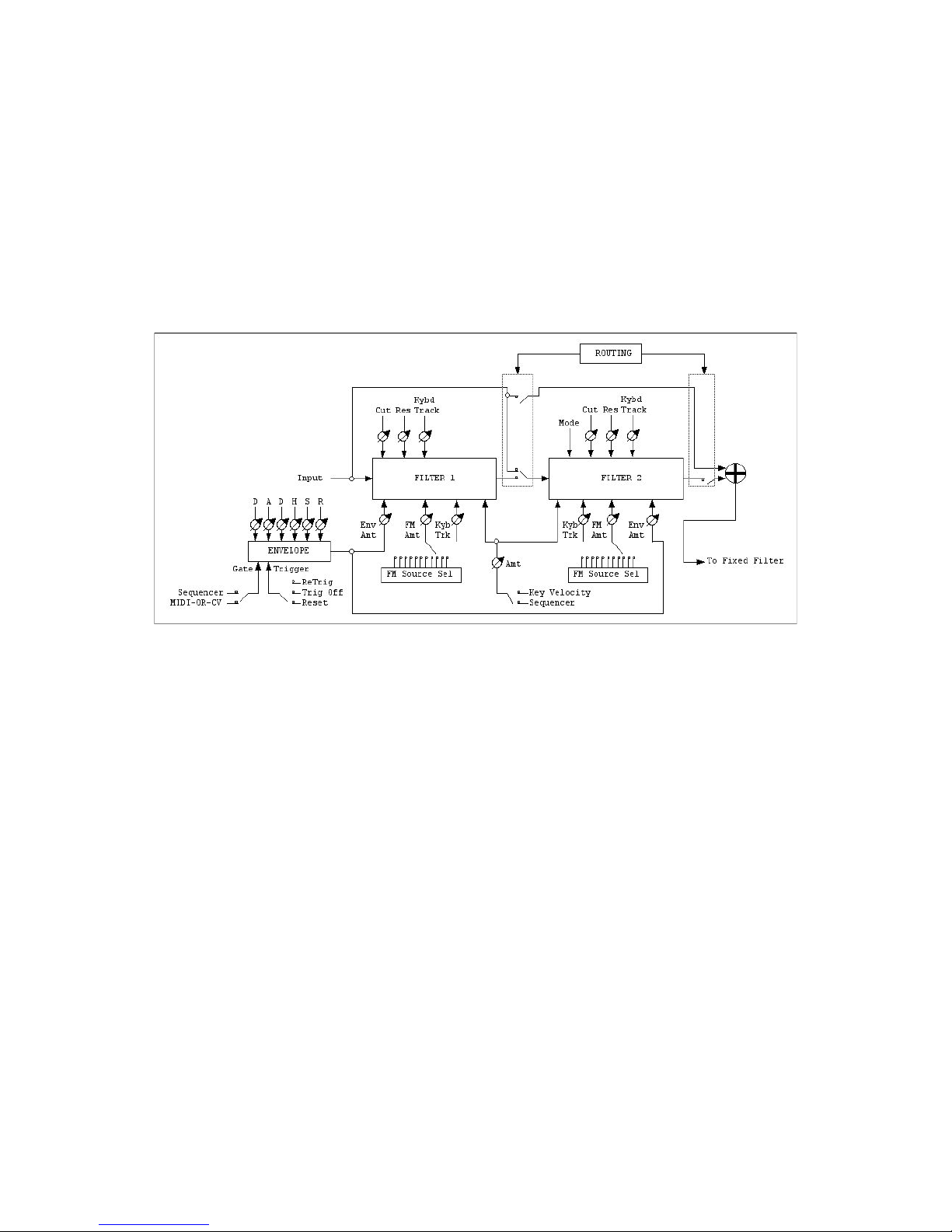
VOLTAGE CONTROLLED FILTER 1-2
Each section of the A8 Synthesizer has a double Filter module comprising a real transistor-ladder 24
dB/Oct Low Pass Filter and a Multi Mode 12 dB/Oct Filter. The two filters can be used in serial
configuration (first LP, then MM), or in parallel mode ( both on the same sources); still, you can
choose to work only with Low Pass or only with Multi Mode.
As usual, each filter has separate controls for Cutoff Frequency and Resonance; a couple of red LEDs
shows when (if any) clipping occurs at the input stage; as you can imagine, rasing the VCOs Levels and
the Resonance are two good ways for see the two LEDs flickering.
Both Filters has indipendent three FM busses: one for Keyboard Tracking, the second for Envelope
Generator, the third for a selection of different modulations and (as on the rest of A8 structure, there
is a fair amount of modulation sources for Cutoff Frequencies).
There is a fourth, common, modulation buss that can be shared between two switchable sources: Key
Velocity (with direct access to the mod summing point for Cutoff Frequency, no EG Level
multiplication) or Sequencer CV (with option for choose which Sequencer Column will drive the
Cutoff); the voltage on this fourth buss will affect both Filters (LP and MM) in equal intensity; e.g.,
there is only one dedicated Amount.
Each Filter (in Upper or Lower section of the instrument) has a dedicated multistage Envelope
Generator: we’ll discuss about it later, in the Modulation Section of this manual.
Page 25
Grp Synthesizer A8 User’s Manual V. 2.06 25
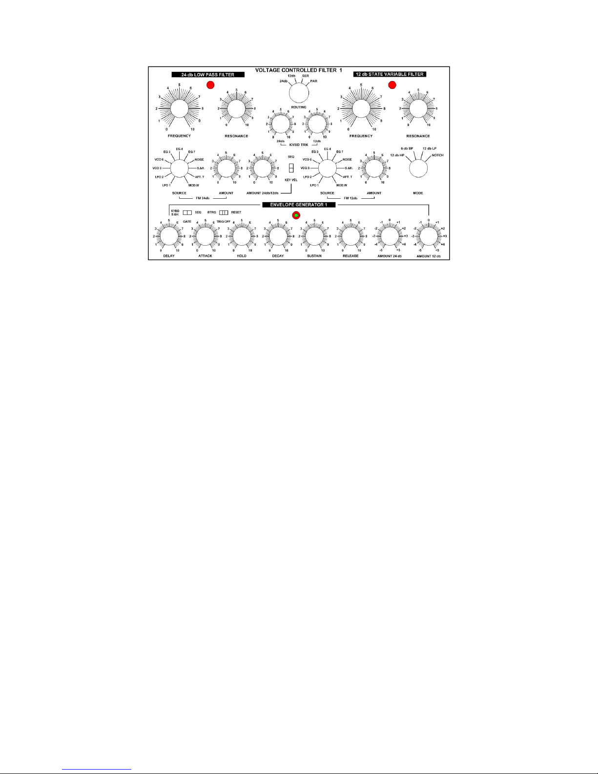
VOLTAGE CONTROLLED FILTER 1-2 REFERENCE
Controls in common for both Filters
In common, both 24 and 12 dB filters shares controls for:
• ROUTING: selection for work with 24 dB/Oct only, 12 dB/Oct only, both filters in Series
connection (first 24 dB, second 12 dB) or both filters in Parallel connection.
• AMOUNT 24 dB/12 dB: the amount of modulation from the source choosen for the
common modulation buss on the Cutoff Frequency. With the following switch, you can
choose between two available sources. The same amount works on both 24 dB and 12 dB
filters.
• KEY VEL/SEQ: the Key Velocity and the Step Sequencer shares the same modulation buss.
This make sense: when the filter is under sequencer control, you’ll probably don’t need the
keyboard velocity on the cutoff frequency. And vice-versa.
Controls for 24dB/Oct transistor-ladder Low Pass Filter
• LED: this red LED glows when the input signal is clipping.
• FREQUENCY: the Cutoff Frequency of the Filter.
• RESONANCE: the Resonance governs the amount of filtered signal routed back at the input
of the circuit; the filter goes into self-oscillation (producing a steady sine tone).
• 24 dB KYBD TRACK: the keyboard tracking amount; operating range: from 0 to 100%.
• AMOUNT 24dB: the dedicated Envelope Generator 1 (Upper) or 4 (Lower) Amount. This
control is bipolar and offers polarity inversion for the connected Envelope Generator. You’ll
find this control near the Envelope knobs, on the lower part of the module; operating range:
+/-5.
• FM 24 dB SOURCE: is the source for the other modulation bus on Cutoff Frequency. You can
choose between many different sources; in full options, they are: LFO 1, LFO 2, VCO 3, VCO
6, EG 1, EG 4, EG 6, EG 7 (only positive-going), NOISE, S&H, AFTERTOUCH,
MODULATION WHEEL.
• FM 24 dB AMOUNT: the amount of modulation from the selected source routed to Cutoff
Frequency.
Page 26
Grp Synthesizer A8 User’s Manual V. 2.06 26
Controls for 12 dB/Oct state-variable Filter
• MODE: selection for the filtering mode; operating range: 12 dB/Oct High Pass resonant, 6
dB/Oct BandPass resonant, 12 dB/Oct LowPass resonant, 6 dB/Oct Notch non-resonant.
• LED: this red LED glows when the input signal is clipping. There’s no problem for occasional
flickering.
• FREQUENCY: the Cutoff Frequency of the Filter.
• RESONANCE: the Resonance governs the amount of filtered signal routed back at the input
of the circuit; the filter goes into self-oscillation (producing a steady sine tone). Be careful! This
module is an hot-rodded version of the classic State Variable design and can goes very bad…
• AMOUNT 12 dB: the dedicated Envelope Generator 1 (Upper) or 4 (Lower) Amount. This
control is bipolar and offers polarity inversion for the connected Envelope Generator. You’ll
find this control near the Envelope knobs, on the lower part of the module; operating range:
+/-5.
• FM 12dB SOURCE: source for the other modulation buss on Cutoff Frequency. You can
choose between many different sources; in full options, they are: LFO 1, LFO 2, VCO 3, VCO
6, EG 1, EG 4, EG 6, EG 7 (only positive-going), NOISE, S&H, AFTERTOUCH,
MODULATION WHEEL.
• FM 12 dB Amount: the amount of modulation from the selected source routed to Cutoff
Frequency.
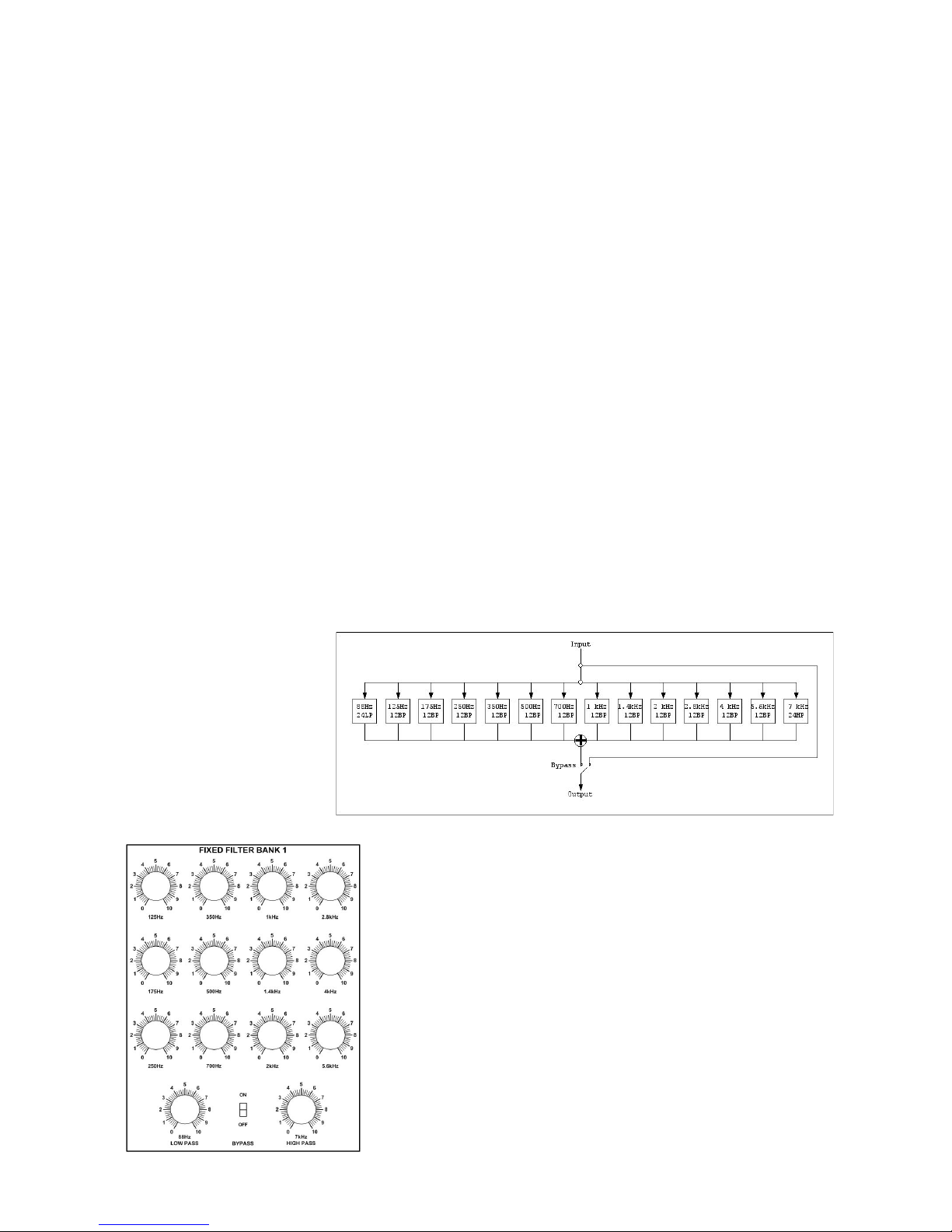
FIXED FILTER BANK
Each section of the instrument has a Fixed Filter Bank, suitable for imposing formants or peculiar kind
of equalization over the
(previously) dynamically
filtered signal. The structure
of fhe FFB is pretty
straightforward: the signal is
treated with 14 separate
band, 12 band pass
12dB/Oct and - at lowest
and highest extremes - one
24 dB/Oct Low Pass and
High Pass.
FIXED FILTER REFERENCE
The module has the following controls (mainly devolved to
individual filters gain):
• Low Pass Level @ 88 Hz.
• Band Pass Level @ 125 Hz, 175 Hz, 250 Hz, 350 Hz, 500
Hz, 700 Hz, 1 kHz, 1.4 kHz, 2 kHz, 2,8 kHz, 4 kHz, 5.6
kHz.
• High Pass Level @ 7 kHz.
• Bypass On/Off: you can entirely bypass the Fixed Filter
Bank.
Page 27
Grp Synthesizer A8 User’s Manual V. 2.06 27
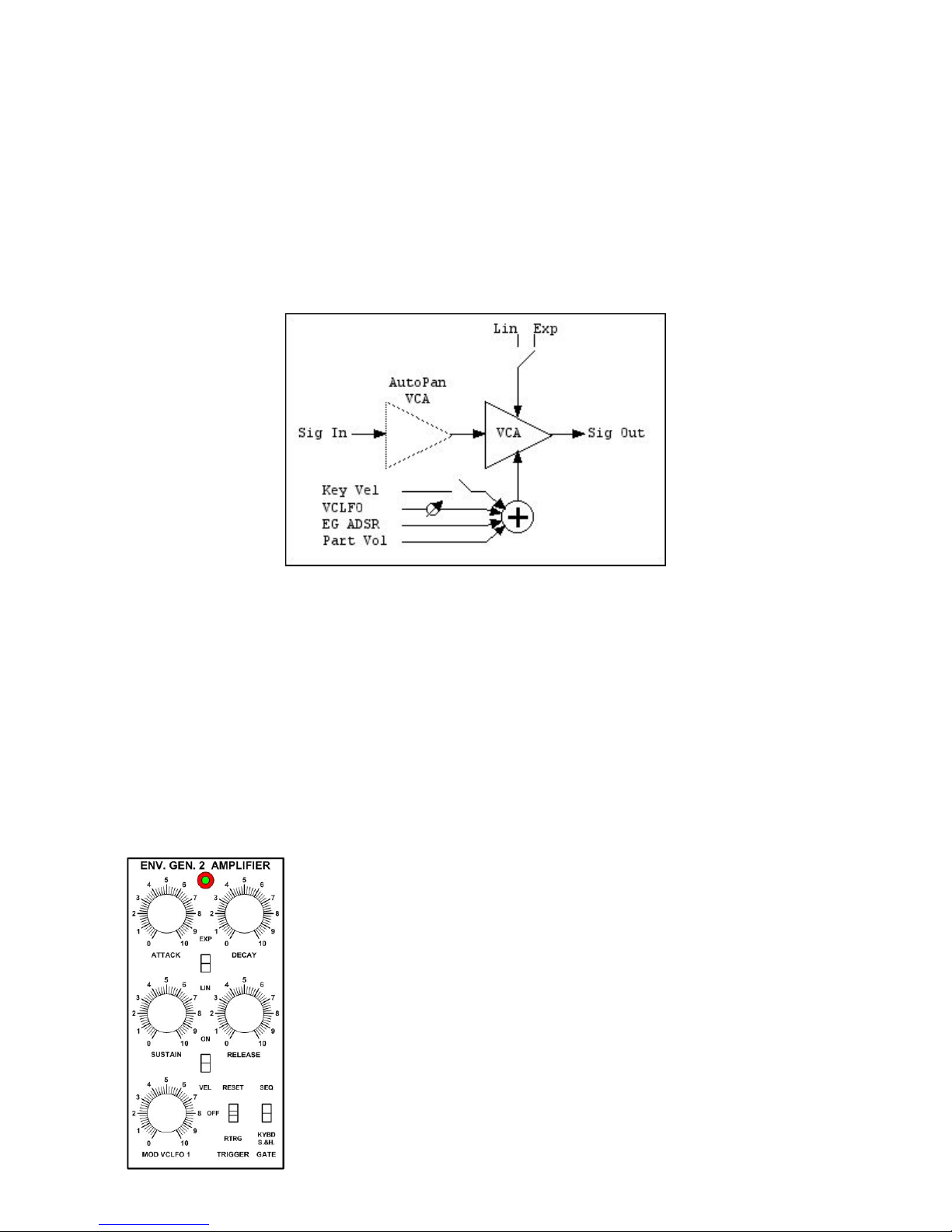
VOLTAGE CONTROLLER AMPLIFIER
With the Voltage Control Amplifier, you can multiply the filtered audio signal(s) with the shape
programmed in the dedicated Envelope Generator (EG 2 on Upper Part, EG 5 on Lower Part);
tweaking the EG parameters, you can reach different kind of articulation in your sound: from slow and
letargic to fast and percussive. We’ll see later the Envelope Generator behaviours. The Amplifier
reacts in Linear or in Exponential shape to the external CVs: you can choose which one is the best for
your needs.
Each VCA Section in the A8 Synthesizer contains two cascaded amplifiers: the first one is involved in
the complex Main Mix / AutoPan structure which we’ll talk later; the second one is the “official” VCA
who drives the articulation of the Upper/Lower Part(s). In the upper scheme, the Part Volume control
is to Upper or Lower Volume control available in the Main Mix / AutoPan Section.
As pointed before, there is a dedicated ADSR Envelope for driving the amplifier; in addition, , is
possible to use the VCLFO 1 (Upper) or 2 (Lower) for obtain sub-audio rate modulation (e.g.:
tremolo) or fast audio rate modulation (e.g. unbalanced AM). On this way, you’ll end with a different
harmonic content: as you probably remember, the AM Output is equal to C, C+M, C-M, where C is
Carrier Frequency (the frequency of the audio signal) and M is the Modulator Frequency (the
modulating audio rate control).
Still, if needed, is it possible to control the amplitude with MIDI Key Velocity.
VOLTAGE CONTR AMPLIFIER REFERENCE
Here are the Voltage Controlled Amplifier controls:
• EXP/LIN Switch: the behaviour of the amplifier in reaction to
external CV. You can choose between Exponential or Linear mode.
• VEL ON/OFF: the switch enable MIDI Key Velocity on VCA Gain.
• MOD VCLFO 1 (or 2): the amount of CV from LFO 1 (Upper Part)
or 2 (Lower Part) for control the VCA level.
As stated before, we’ll talk later about the dedicated ADSR Envelope
Generator functions and controls.
Page 28
Grp Synthesizer A8 User’s Manual V. 2.06 28
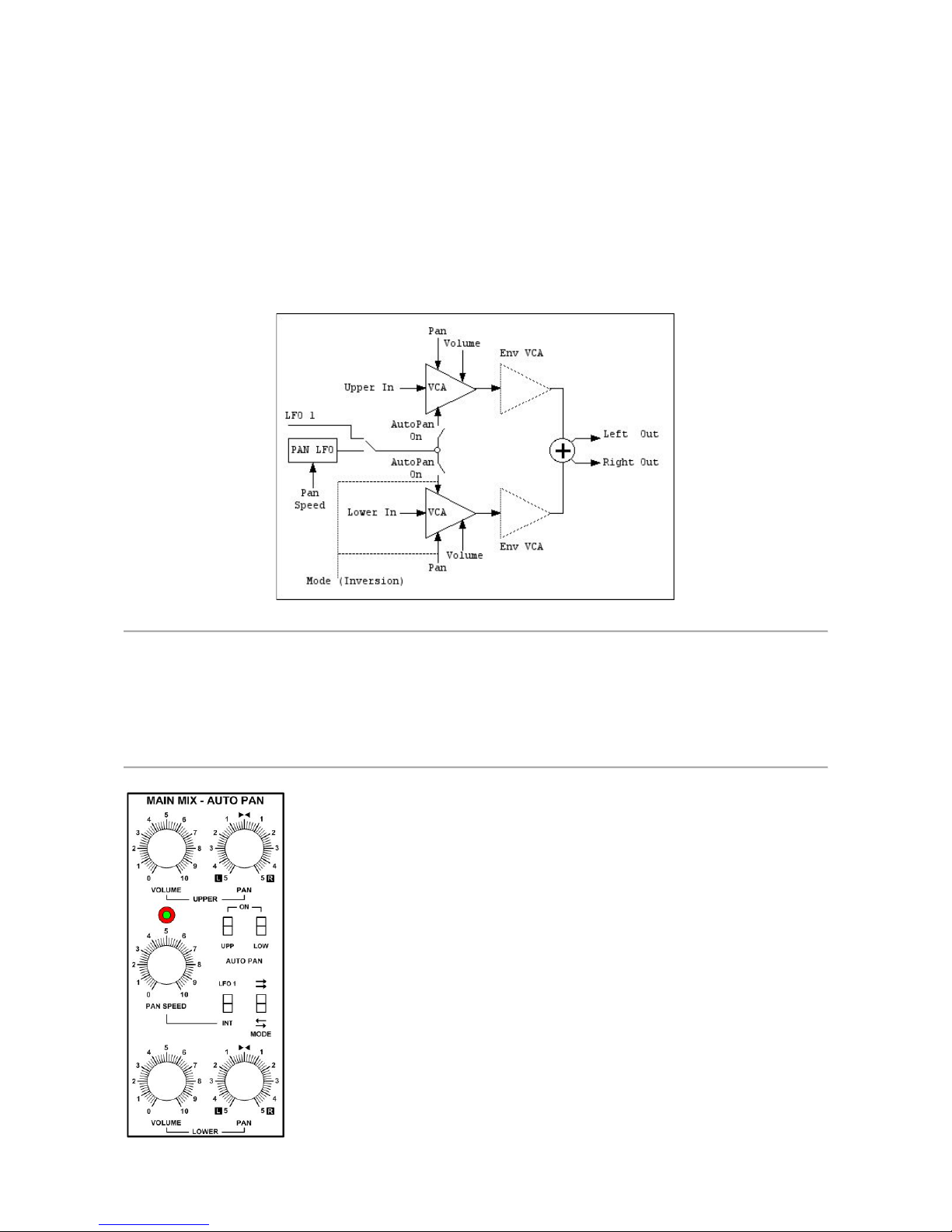
MAIN MIX / AUTO PAN
In this module, at last, both Upper and Lower section are joined together toward the final output of
the entire instrument. Each section has separate controls for Volume, static Pan position (mono
in/stereo out) and AutoPan enable switch. The pan position(s) of the signal(s) can be automated with
an integrate triangle-wave LFO or with the VCLFO 1 of the Upper Section. Still, you can choose
parallel or cross pan motion for Upper/Lower Section; in parallel mode, both Upper and Lower
signals moves in the same direction; in cross mode, the pan position movements are mirrored.
Note
If you select the mirrored/cross pan motion, the Lower (static) Pan control works in inverted mode; e.g.: full cw = all Left,
full ccw = all Right.
While the dedicated LFO Speed goes sufficiently fast for AutoPan, if you want to drive very high the sound movement,
don’t forget to choose the LFO 1 as Pan Source;: as soon as you reach the audio rate, the harmonic content of the signals
will change according to AM rules.
MAIN MIX / AUTO PAN REFERENCE
Controls for the Upper Section:
• VOLUME: the level of the Upper synthesis channel.
• PAN: the static position of the signal in the stereo field.
• (Auto Pan) UPPER ON: this switch enable the LFO pan modulation
for the Upper signal.
Controls for the Lower Section:
• VOLUME: as above.
• PAN: as above.
• (Auto Pan ) LOWER ON: as above.
Page 29
Grp Synthesizer A8 User’s Manual V. 2.06 29
Controls for the Auto Pan Section:
• PAN SPEED: the rate for automatic pan movement. The upper LED will flash (in time) in red
when the internal LFO is selected, will flash in blue when the LFO 1 is selected. The Pan
Speed goes pretty high, but - as said above - if you need to dig deeply into audio rate AM,
you should choose the LFO 1 as pan source.
• LFO 1/INT: this switch choose the modulating source for the Auto Pan movement.
• MODE: this switch choose between parallel motion (both Upper and Lower Sections moves
with the same direction, in respect of the individual static PAN positions) or cross mirrored
motion (when Upper is left, Lower is right and vice versa).
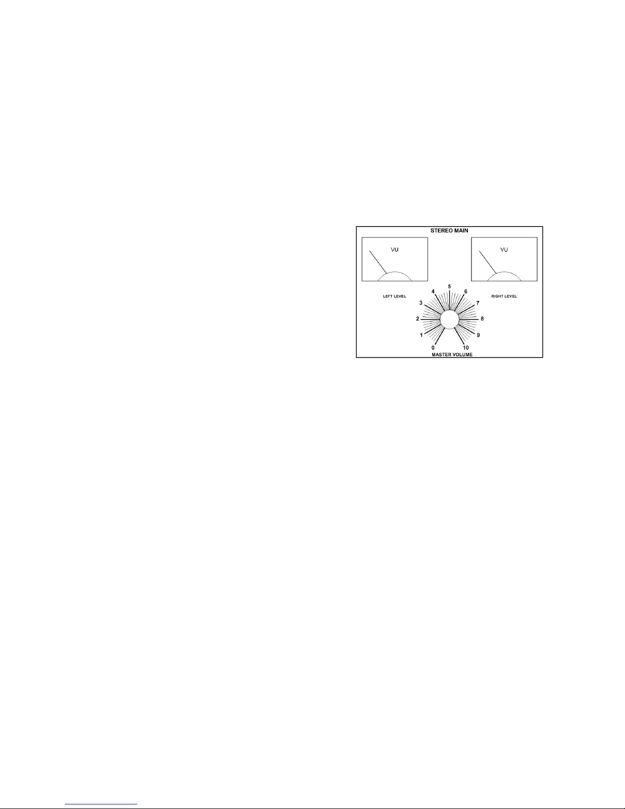
STEREO MAIN
This is the “big knob” for the final main volume of the
entire synthesizer; while it’s pretty straigthforward, you
should keep in mind two things:
• this is a buffered potentiometer; whatever level
you set, you’ll always have 1000 Ohm.
• the couple of VuMeters has a fairly limited visual
dynamic range (-14/+3); so, if you want to see
needles dancing, you’ll be probably forced to set an high out level. Beware! The A8
Synthesizer can be very LOUD.
Page 30
Grp Synthesizer A8 User’s Manual V. 2.06 30
A8 MODULATION SOURCES AND CONTROL MODIFIERS
In the Grp A8 Synthesizer, you can use several types of modulation:
• DC constant Modulations: e.g., the CV informations from MIDI/Analog Keyboards; they are
steady values applied to oscillators and filter frequencies.
• Transient Modulations: e.g., the CV outputs from the seven Envelope Generators. They’ll
follow their stages, from Note On till Note Off and then (hopefully) they’ll settle down until
the next Gate On.
• Cyclical Modulations: e.g., the CV outputs from the three Low Frequency Oscillators. They’ll
generate a control with a shape (waveform) and rate (frequency) well definable by the user.
• Random Modulations: e.g., the CV outputs from the Sample & Hold module. You’ll can patch
the system for randomly pick values from several S&Hed sources.
• Programmable Modulations: e.g., the dual CV outputs from the internal Step Sequencer
Module. You can program both columns in 16x1 or 8x2 fashion for drive oscillators
frequencies and PW or filter cutoff frequencyes. As we’ll see after, you’ll can realize complex
real-time interactions with Step Sequencer and MIDI/CV Inputs.
Note
To be fully honest, there is a sixth kind of audio rate modulation source into the Grp A8 Synthesizer: you can use (…you
should try it!) the VCO signals for lin/exp (cross) modulate the frequency of VCOs and Filters.
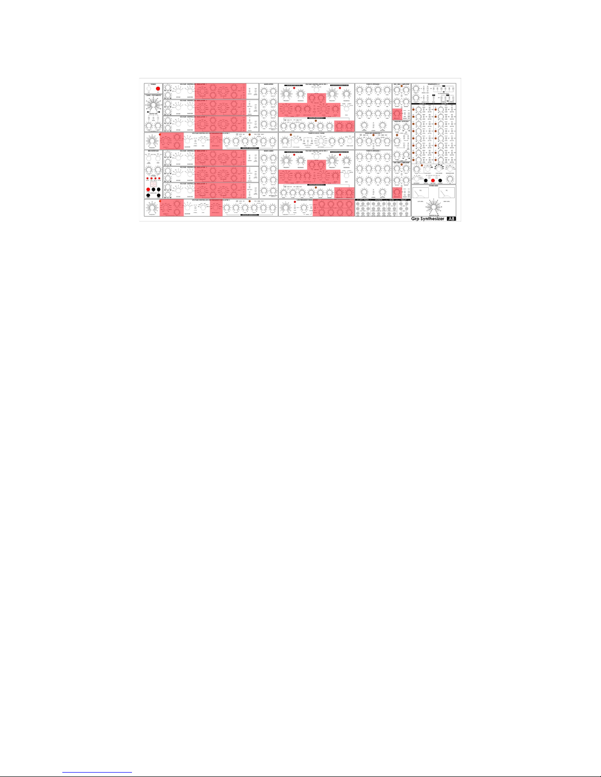
The over simplified drawing above shows the available modulation sources. Following, you’ll find a
picture of the front panel with the highligted positioning of the modulation sources.
Page 31
Grp Synthesizer A8 User’s Manual V. 2.06 31
The above illustration shows the destinations and the amounts of modulation routings. When you’ll
start with sound experiments, it’s a good rule to begin turning all them off.
Modulation Sources
Here is a list of the available modulation sources:
• VCO 1.
• VCO 2.
• VCO 3.
• VCO 4.
• VCO 5.
• VCO 6.
• Noise Generator.
• VC LFO 1.
• VC LFO 2.
• LFO 3.
• Sample & Hold.
• Envelope Generator 1 DAHDSR.
• Envelope Generator 2 ADSR.
• Envelope Generator 3 DHADSR.
• Envelope Generator 4 DAHDSR.
• Envelope Generator 5 ADSR.
• Envelope Generator 6 DHADSR.
• Auxiliary Envelope Generator 7 ADSR.
• Step Sequencer Column A.
• Step Sequencer Column B.
• Keyboard Tracking.
• MIDI Pitch Bend.
• MIDI Mod Wheel.
• MIDI Channel Aftertouch.
• MIDI Key Velocity.
• Filter 24 dB Ext CV In.
• Filter 12 dB Ext CV In.
Modulation Destinations
Here is a list of the available modulation destinations:
• VCO 1 PWM, Linear Frequency Modulation, Exponential Frequency Modulation.
Page 32

Grp Synthesizer A8 User’s Manual V. 2.06 32
• VCO 2 PWM, Linear Frequency Modulation, Exponential Frequency Modulation.
• VCO 3 PWM, Linear Frequency Modulation, Exponential Frequency Modulation.
• VCO 4 PWM, Linear Frequency Modulation, Exponential Frequency Modulation.
• VCO 5 PWM, Linear Frequency Modulation, Exponential Frequency Modulation.
• VCO 6 PWM, Linear Frequency Modulation, Exponential Frequency Modulation.
• VCF 1 24 dB Cutoff.
• VCF 1 12 dB Cutoff.
• VCF 2 24 dB Cutoff.
• VCF 2 12 dB Cutoff.
• VCA Upper Amplitude
• VCA Lower Amplitude
• Upper Section Pan Position
• Lower Section Pan Position
• VC LFO 1 Frequency, Output Shaping.
• VC LFO 2 Frequency, Output Shaping.
• LFO 3 Output Shaping.
From here, we’ll explain the behaviour of the different modulation sources and modifers available in
the synthesizer.
Page 33
Grp Synthesizer A8 User’s Manual V. 2.06 33
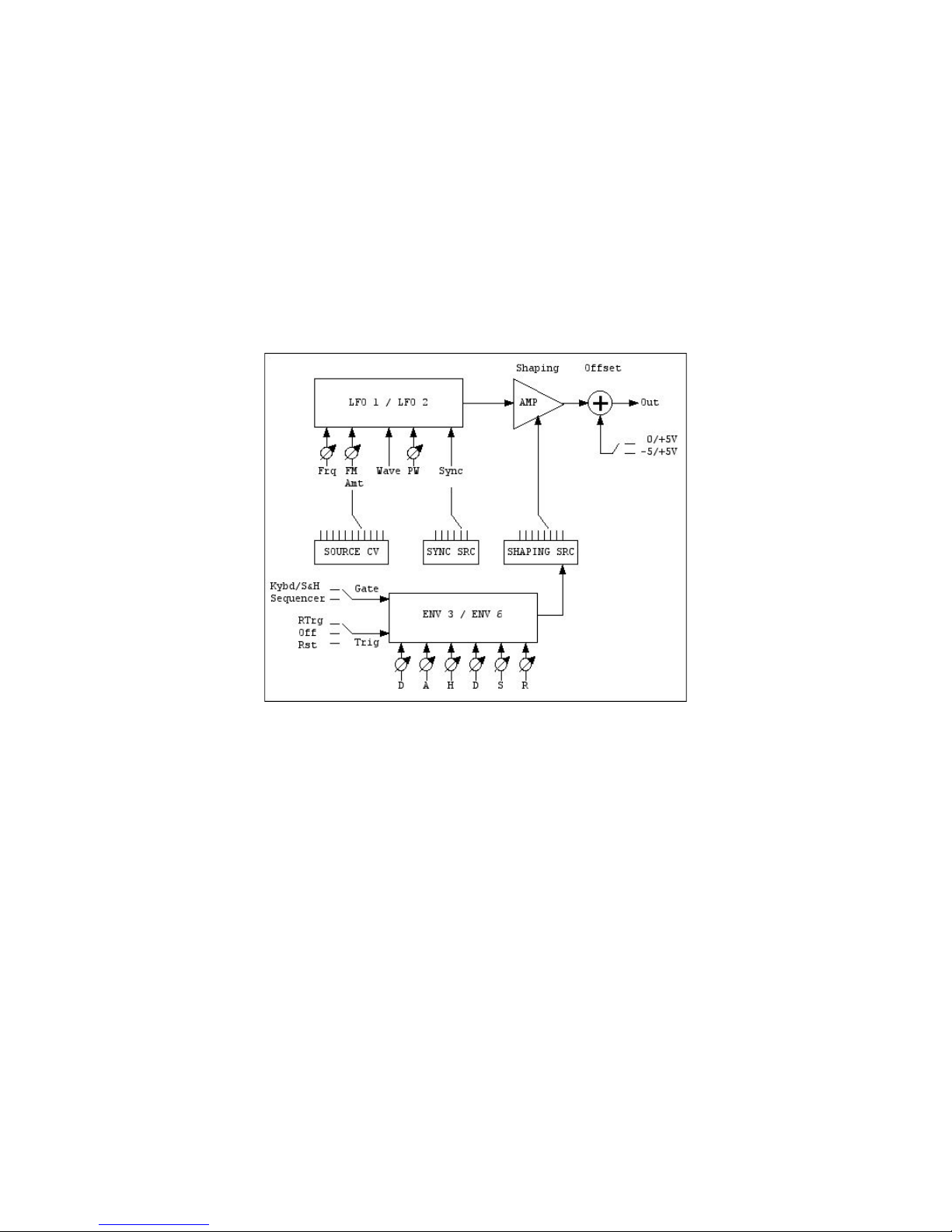
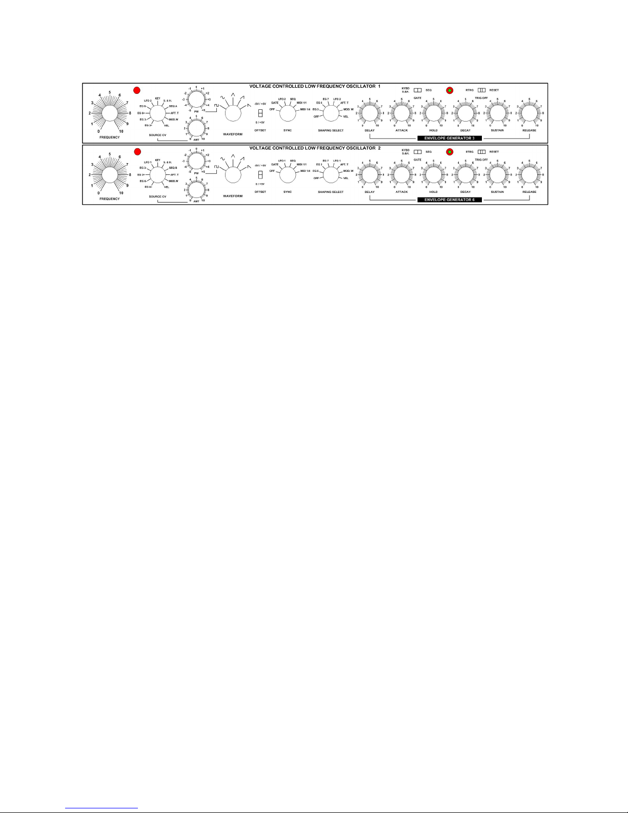
VOLTAGE CONTR LOW FREQUENCY OSCILLATOR 1-2
The two main voltage controlled LFOs are pretty similar (few differences are found in the external
control sources list) and are mainly at disposal of the Upper (LFO 1) and Lower (LFO 2) sections;
however, you can reassign them using the multi-position selectors available on the front panel.
As you probably know, the main goal of an Low Frequency Oscillator is to produce a periodic CV,
useful for vibratos and tremolos), whose shape and speed are governed from waveform and
frequency choosed by the user; in addition, VC LFO 1-2 can goes very up in the audio range, reaching
a whopping 2,2 kHz that you’ll appreciate for experiments with FM/AM.
The behaviours of the VC LFO 1-2 are organized in few main areas: Frequency Setting and Frequency
Modulation from different external sources; Waveform Selection and Pulse Width Modulation; Hard
Sync Setting from several external sources; Output Offsetting and Shaping thru different external
sources, enclosing a dedicated Envelope Generator (more on this later).
Frequency Control
The nominal frequency of the LFO spans between one cycle every 45 secs and 1.7 kHz; the
Frequency knob sets the desired rate and the red LED flashes in time; don’t forget that the LFO
Frequency can be externally modulated with one of eleven possible sources: the more positive CV
goes into the LFO (you can adjust the Source CV Amount), the fastest will be the speed. Still, is it
possible to reset in Hard Sync mode the LFO cycle to one of six (with an “off - no sync” position)
sources: due to the analog nature of the circuit, the Sync capabilities should be intendend as a cyclereset and not as a “crystal quartz clear” time alignment on external sources; the different behaviour
could be pretty evident at low speed.
Waveform Control
The shape of the modulation is a consequence of the choosen waveform; there are five main
waveforms available (sine, triangle, sawtooth, ramp, square) and, thanks to the analog nature of the
LFO circuit, is it possible to modulate the shape/simmetry of the square wave, obtaining all the
desidered Pulse Widths.
Page 34
Grp Synthesizer A8 User’s Manual V. 2.06 34
Hard Sync
As said before, the cycle of the VC LFO 1-2 can be interrupted and restarted under external sync
control; in this way, you can assure that (e.g.) every time you press a note, the LFO will always start
from the same point in its waveform. There are six available sync sources: Off Sync, Keyboard Gate,
the other VC LFO, the Step Sequencer Clock, MIDI synchronization for 1 LFO cycle every bar or for
1 LFO cycle every quarter note.
Don’t forget that you can sync LFO 1 to LFO 2 and LFO 2 to LFO 1…
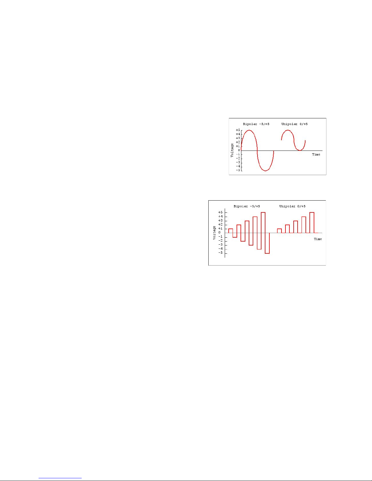
Output Offset
If you use LFO 1-2 for frequency modulating the VCOs, sooner
or later you’ll need the rectifying/offsetting capability to start the
tune modulation from zero, e.g. from the nominal frequency of
the VCO. With the Offset switch, you can choose if the
waveshape from LFO spans in the entire CV range -5/+5V (ten
octaves, five above and five below the nominal frequency of the
modulation destination) or is best suited for your needs to limit
its range only to the positive field of values 0/+5V (five octaves,
starting from 0 V, the nominal frequency of the modulation
destination).
If you are using Square Wave for low frequency
modulation on VCO tuning:
• in the first case (bipolar range), turning clockwise
the FM Amount on the VCO you’ll end with a
broad and broad trill whose speed is the LFO
Frequency and interval is the VCO FM Amount,
costantly out of tune with the nominal frequency
of the VCO except the rarest cases of
symmetrical values (+/-1, 2, 3, 4, 5 octaves).
• in the second case (unipolar range), turning clockwise the FM Amount on the VCO, you’ll end
with a trill that will start always from the lowest value = 0V, the nominal frequency of the VCO.
In this way, it will be more easiest to obtain tuneable intervals.
Shaping
The Shaping capabilities allows to vary in time the amplitude of the control signal outputted from the
LFO. There are several shaping sources, enclosed a dedicated Envelope Generator for modulation
fade in/fade out, comprising MIDI Key Velocity, Modulation Wheel position, Channel Aftertouch value,
the other VC LFO value, the auxiliary Envelope Generator 7, several other EGs available in the A8
structure.
Page 35
Grp Synthesizer A8 User’s Manual V. 2.06 35
VOLTAGE CONTR LOW FREQUENCY OSCILLATOR 1-2
REFERENCE
As stated before, there are only few differences between the two main LFOs; following, we’ll give
description of every available control.
Frequency Controls:
• FREQUENCY: the LFO rate; from 45 sec to 1700 Hz.
• LED: visual indication for frequency of the selected wave and shape for the square/pulse wave.
• SOURCE CV: source of Frequency Modulation; you can choose between: EG 3 + (positive
going), from the dedicated Envelope Generator in LFO 1; EG 3 - (negative going), from the
dedicated Envelope Generator in LFO 1; EG 6+ (positive going), from the dedicated Envelope
Generator in LFO 2; EG 6- (negative going), from the dedicated Envelope Generator in LFO
2; LFO 2 (available only in VC LFO 1), Freq Mod from LFO 2; LFO 1 (available only in VC
LFO 2), Freq Mod from LFO 1; KEY, the keyboard control voltage; S&H, from the common
Sample & Hold/Noise Module; SEQ A (available only in VC LFO 1), from the A-column of the
Step Sequencer; SEQ B (available only in VC LFO 2), from the B-column of the Step
Sequencer; AFT.T., from MIDI Channel Aftertouch, MOD.W, from MIDI Modulation Wheel,
VEL, from MIDI Key Velocity.
• (SOURCE CV) AMT: modulation amount for the selected source.
Waveform Controls:
• WAVEFORM: you can choose between square (variable pulse), sine, triangle, ramp, saw.
• PW: pulse width for the selected square wave.
• OFFSET Switch: you can choose between unipolar range (0/+5V) or bipolar (-5/+5V) for the
waveforms.
Sync Controls:
• SYNC: selection for the (hard) sync source; you can choose between: OFF, no (hard) sync;
GATE, sync/restart on the keyboard Gate On; LFO 2, (available only in VC LFO 1), from LFO
2; LFO 1, (available only in VC LFO 2), from LFO 1; SEQ, the Step Sequencer Clock
Generator; MIDI 1/1, sync the LFO cycle on every 4/4 bar of external MIDI Clock; MIDI 1/4
sync the LFO cycle on every quarter of external MIDI Clock.
Page 36
Grp Synthesizer A8 User’s Manual V. 2.06 36
Shaping Controls:
• SHAPING SELECT, the modulation source for the LFO amplitude; you can choose between:
OFF, no shaping (a constant value keeps always on the LFO output); EG 3, thru dedicated
Envelope Generator in LFO 1; EG 6, thru dedicated Envelope Generator in LFO 2; EG 7, thru
auxiliary common Envelope Generator 7; LFO 2, available only in LFO 1; LFO 1, available only
in LFO 2; AFT.T., the MIDI Channel Aftertouch; MOD.W, the MIDI Modulation Wheel; VEL,
the MIDI Key Velocity.
As you can imagine, well’talk later about the embedded Envelope Generators 3 and 6 controls.
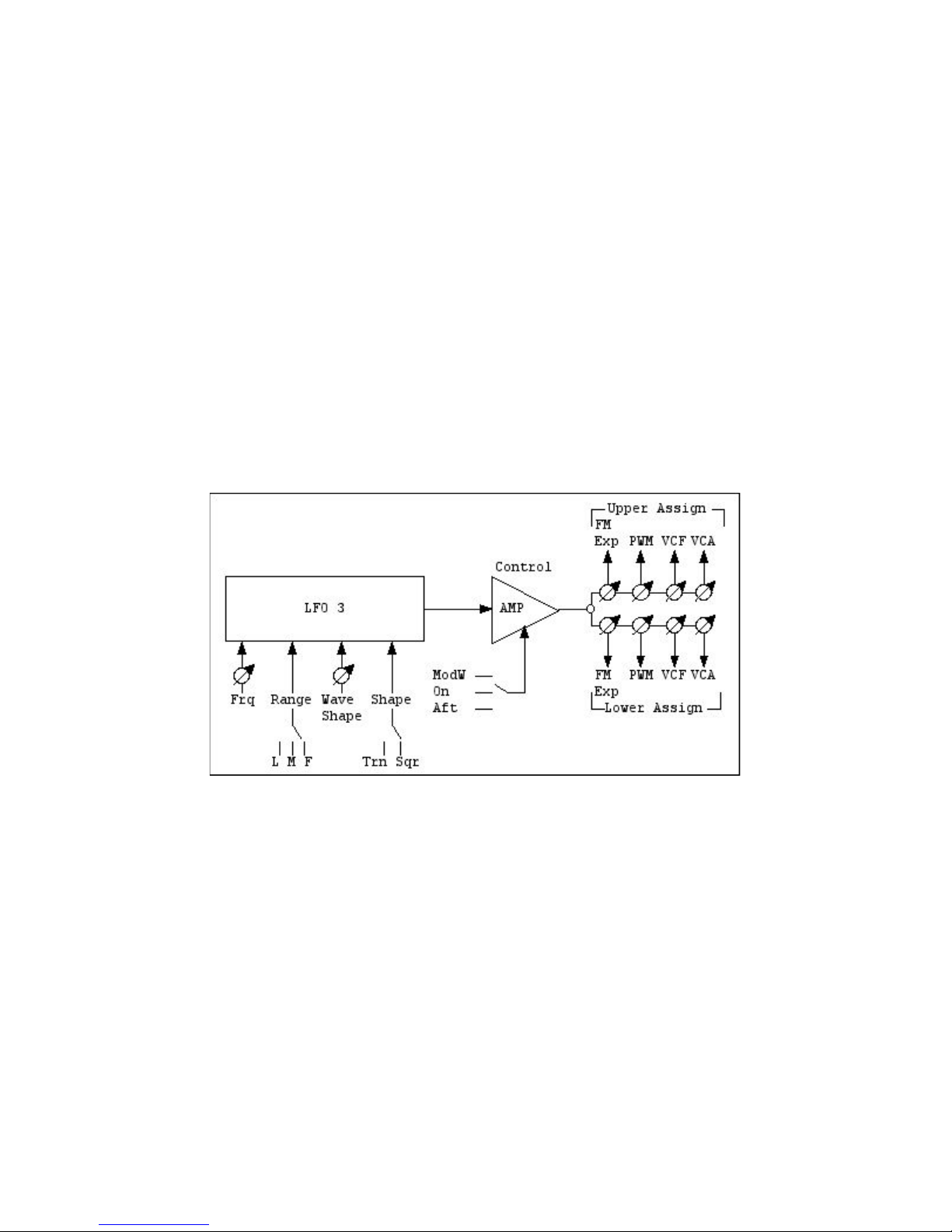
LOW FREQUENCY OSCILLATOR 3
The LFO 3 works for both Upper and Lower Sections of the Synthesizer: the user can adjust
indipendently modulation amounts for four indipendent destinations (VCO Exp FM, VCO PWM, VCF
Cutoff, VCA Amp) on the Upper and the Lower Sections. Obviously, as there is only one LFO 3, its
waveshape and frequency will be the same for both sections and eight modulation amounts.
The structure of the LFO 3 is more “performance oriented” than LFO 1-2; it lacks external FM or
Sync, but offers several nifty options; it offers mainly options for adjust: Frequency and Frequency
Range, Waveshape, Realtime output shaping control, eight separate Modulation routings (four Upper
and four Lower).
Frequency and Frequency Range
The rate of LFO 3 can be set in three different ranges, Fast, Mid and Slow, whose span covers audio
and sub-audio rate. As usual, the Frequency control and a red LED permits easy adjustment and rate
visualization.
Waveshape
As on other great mono machine of the past, the A8 Synthesizer offers in the LFO 3 two main waves,
triangle and square, that can be freely altered from the user. On this way, you can obtain all the
intermediate values from sawtooth - triangle - ramp and all the different pulse widths, starting from
square wave, till 1% to 99%.
Page 37
Grp Synthesizer A8 User’s Manual V. 2.06 37
Output Control
You can choose if have permanently on the CV outputted from LFO 3 or re-shape its amplitude
scaling with Modulation Wheel position or Channel Aftertouch value. As you can imagine, this is
appliable only when the A8 Synthesizer is under MIDI control.
Modulation Routings
The LFO 3 outputs eight different amounts of the same CV (same waveform, same frequency)
towards the available Upper and Lower destinations.
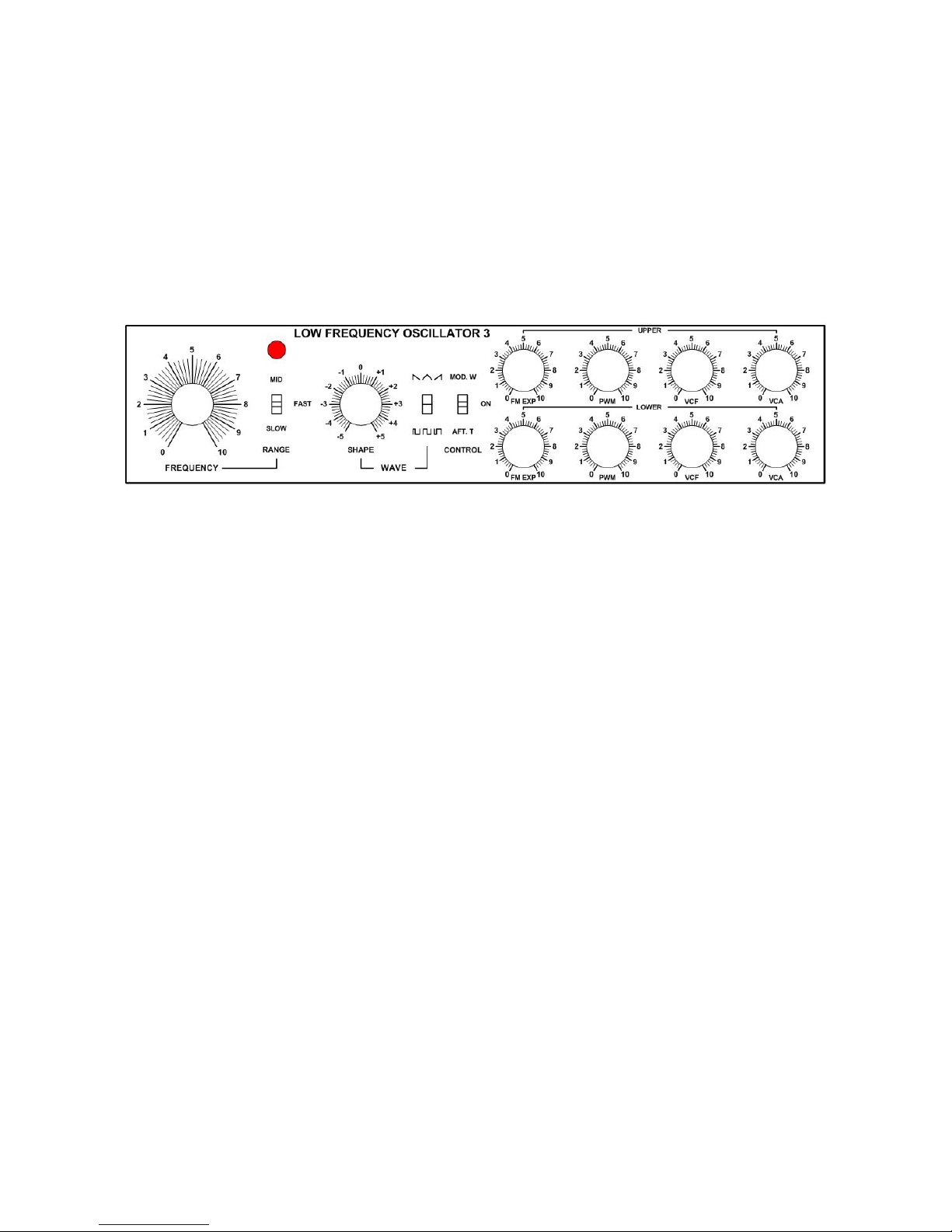
LOW FREQUENCY OSCILLATOR 3 REFERENCE
Frequency Controls:
• LED: flash at LFO 3 Frequency.
• FREQUENCY: the speed of LFO 3; three ranges available, see below.
• (FREQUENCY) RANGE: Fast (75-2700 Hz), Mid (2 - 91 Hz), Slow (10”-4 Hz).
Waveshape Controls:
• WAVE SHAPE: control for simmetry of Square/Pulse and Saw/Triangle/Ramp wave. See
below.
• (WAVE) SELECT SWITCH: In upper position, you gain access to Saw/Triangle/Ramp wave,
continously shapable with previous WAVE SHAPE control. In lower position, you gain access
to Square/Pulse wave, continously shapable with previous WAVE SHAPE control.
Output Control Controls:
• CONTROL: three position switch for selection of LFO 3 Amplitude Modulation source: you
can choose between: MOD W: the Modulation Wheel position sets the amount of LFO 3
output; ON: constant value; the LFO 3 output is always fully open; AFT.T; the Channel
Aftertouch value sets the amount of LFO 3 output.
Destination Controls:
• UPPER DESTINATIONS: the modulation destinations; you have separate amount for: FM
EXP: exponential frequency modulation on all three VCOs; PWM: shape modulation on all
three audio Square Waves (if available); VCF: cutoff frequency modulation on all two VCFs;
VCA: amplitude modulation on the VCA; LOWER MODULATION: same as above.
Page 38
Grp Synthesizer A8 User’s Manual V. 2.06 38
Note
With LFO 1 on Auto Pan and LFO 3 on Upper/Lower VCA you can superimpose two simultaneous AM treatments on
audio signals.
ENVELOPE GENERATORS
The A8 structure contains seven indipendent EGs positioned in logical points of the signal flow; in
addition, each EG output is available in the modulation source list of the instrument:
• Envelope Generator 1: controls, with separate bipolar amounts, the cutoff frequencies of Low
Pass and State Variable Filters in Upper Section.
• Envelope Generator 2: controls, always at full amount, the gain of Voltage Controlled
Amplifier in Upper Section.
• Envelope Generator 3: controls, always at full amount, the output level of VC LFO 1 in the
Upper Section.
• Envelope Generator 4: controls, with separate bipolar amounts, the cutoff frequencies of Low
Pass and State Variable Filters in Lower Section.
• Envelope Generator 5: controls, always at full amount, the gain of Voltage Controlled
Amplifier in Upper Section.
• Envelope Generator 6: controls, always at full amount, the output level of VC LFO 1 in the
Upper Section.
• Envelope Generator 7: is an auxiliary envelope, freely assignable to Upper or Lower Section.
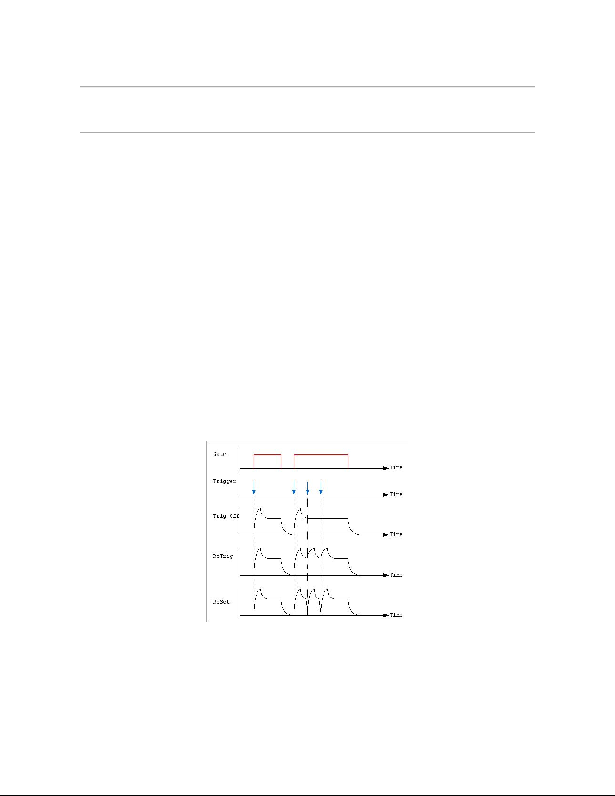
Common behaviours and controls - Trigger Mode
All seven Envelope Generators can be controlled in their interaction with Gate and Trigger.
While each EG is always under Gate control, there is a three-position switch for Trigger action:
• TRIG OFF position: the selected envelope works only with Gate. Any Trigger received will be
simply ignored.
• R(e)TR(i)G position: when the selected envelope receive a Trigger impulse (indipendently
from the current Gate On/Off state) it will restart the Attack stage from the current value.
• RESET position: when the selected envelope receive a Trigger impulse (indipendently from
the currente Gate On/Off state) it will restart the Attack stage always from zero value.
Page 39
Grp Synthesizer A8 User’s Manual V. 2.06 39
Common behaviours and controls - Gate source select
Each Envelope Generator can be “sintonized” on one of two possibile Gate Source using a dedicated
two-position switch:
• KYBD S&H position: the selected envelope is fired from any Gate On received thru MIDI
Interface OR from the analog Gate Input ports OR from the internal Sample & Hold module.
• SEQ position: the selected envelope is gated from the internal Step Sequencer.
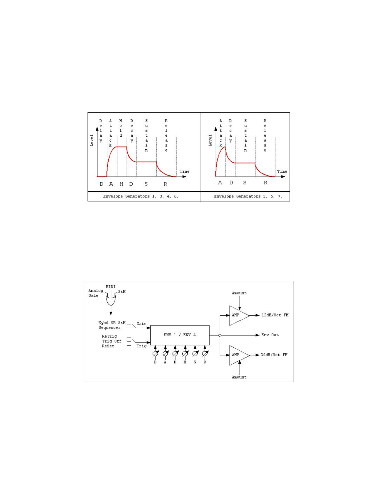
Common behaviours - Envelope Structure
The most complex envelopes are located in the Filter Modules (Upper and Lower) and in the VC
LFO Modules (Upper and Lower); they have a 6-stage structure with Initial Delay, Attack Time, Hold
Time, Decay Time, Sustain Level and Release Time.
The most standard envelopes are located in the VCA Modules (Upper and Lower) and in the
Auxiliary EG 7 Module (common to both sections); they have a classical 4-stage structure with Attack
Time, Decay Time, Sustain Level and Release Time.
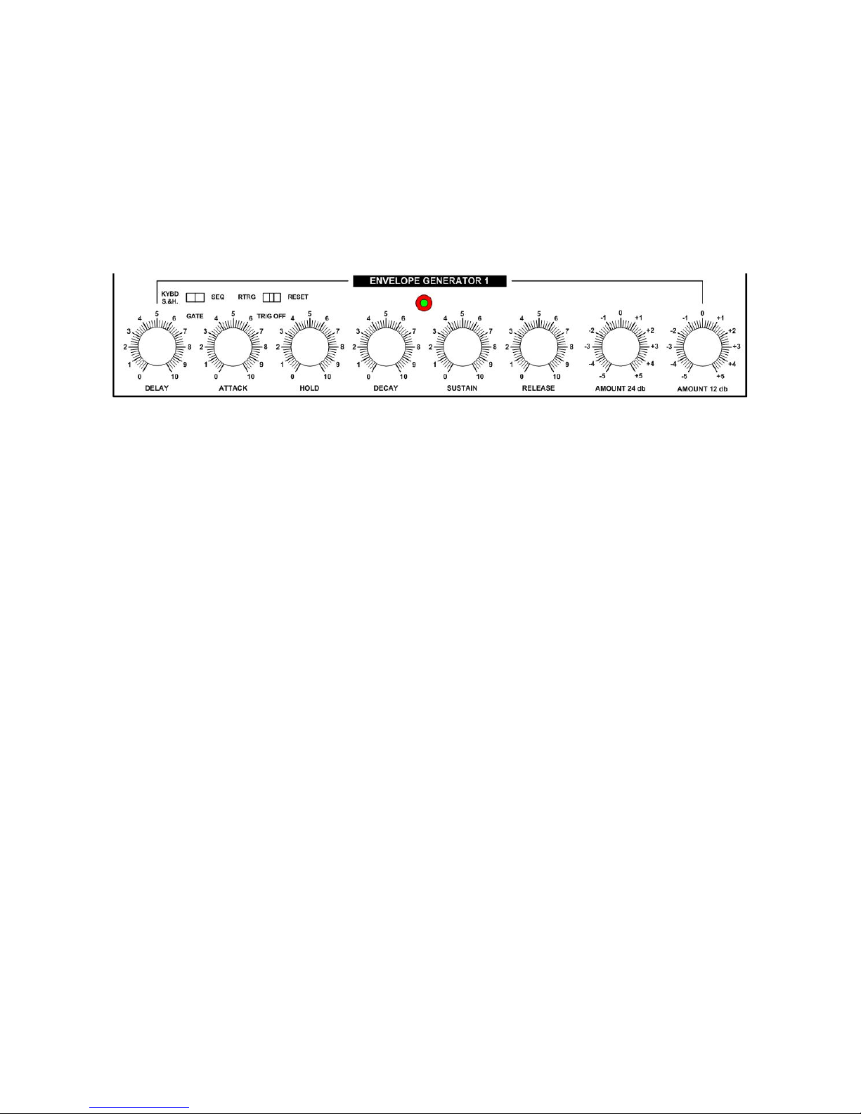
SIX STAGE ENVELOPE GENERATOR (ENV 1 / ENV 4)
The EG 1 and 4 are embedded into the Upper and Lower Filter modules; each envelope drives two
filters - one Low Pass, one State Variable - thru a couple of indipendent bipolar Amount controls.
The structure of the envelope is straightforward and, as you can see from the above scheme, is it
possible to mimic the classic “clipped decay” envelope from historical vintage mono synths or, if
needed, obtain several kind of articulation contours.
This kind of envelope has three separate control outputs:
Page 40
Grp Synthesizer A8 User’s Manual V. 2.06 40
• Towards the Low Pass Filter - thru dedicated bipolar Amount control.
• Towards the State Variable Filter - thru dedicated bipolar Amount control.
• Direct CV Output; it goes into the modulation source list.
As told before, is it possible to drive the envelope with Gate from Keyboard (Analog and MIDI)
ORed with Sample & Hold; the Trigger (from analog ports or from MIDI interface) can be ignored,
used for ReTrigger or for forced ReSet.
SIX STAGE ENVELOPE GENERATOR (ENV 1/ ENV 4)
REFERENCE
Envelope stages parameters:
• DELAY Time: 0 msec to 15 sec. It defines the timing interval between Note On/Gate On
command and the start of the Attack Time. This stage is unaffected in the optional retriggering
configuration.
• ATTACK Time: 1 msec to 15 sec; log curve. It defines the timing interval from initial minimum
value to maximum value. The optional retriggering starts from this stage.
• HOLD Time: 0 msec to 15 sec. It defines the timing interval of permanence at highest
possible level, before beginning the Decay segment.
• DECAY Time: 1 msec to 15 sec; exp curve. It defines the timing interval for moving from the
highest possible level towards the Sustain Level.
• SUSTAIN Level: 0 to 100%. The Sustain Level lasts as long as the Gate On signal; as soon as
Gate turns Off, the envelope leaves Sustain Level and begins Release Time.
• RELEASE Level: 1 msec to 15 sec; exp curve. It defines the timing interval from Sustain Level
back to minimum (initial) level.
Gate (source) parameters:
• KYBD S&H position: the envelope is fired from Gate On received thru MIDI Interface or from
the analog Gate Input ports OR from the Clock signal emitted from Sample & Hold module.
• SEQ position: the envelope is gated from the Step Sequencer.
Trig switch parameters:
• R(e)TR(i)G position: when the envelope is retriggered, it will restart from the current value.
• TRIG OFF position: the envelope ignore triggers and works only with Gate.
• RESET position: if the envelope is retriggered, it will forced to restart from level zero.
Page 41
Grp Synthesizer A8 User’s Manual V. 2.06 41
Activity LED:
• The red colour is for Gate received from MIDI OR from the analog Gate Input Ports OR from
the Sample & Hold module.
• The blue colour is for Gate received from the Step Sequencer.
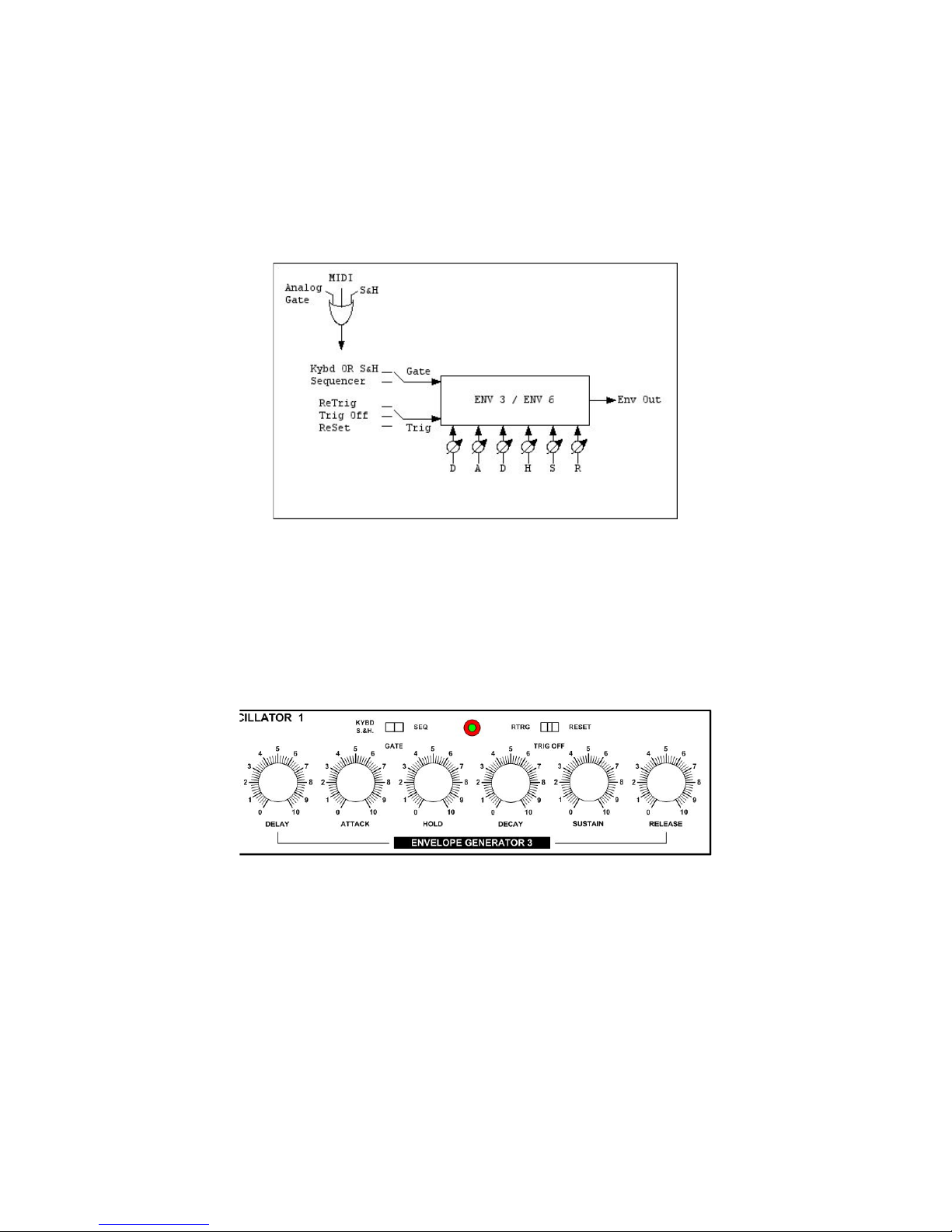
SIX STAGE ENVELOPE GENERATOR (ENV 3 / ENV 6)
The Envelope Generators 3 and 6 are embedded in the VC LFO 1-2 modules and can be used
mainly for shaping the LFO output amplitude; however, their control signals are available into the
modulation source list of the instrument.
In spite of EGs 1 / 4, the EGs 3 / 6 lacks the dedicated Amount controls: every kind of attenuation
should be done directly at the modulation destination stage.
SIX STAGE ENVELOPE GENERATOR (ENV 3 / ENV 6)
REFERENCE
You can refer to the previous reference description.
Page 42
Grp Synthesizer A8 User’s Manual V. 2.06 42
FOUR STAGE ENVELOPE GENERATOR (ENV 2 / ENV 5)
Those two EGs are embedded into the Upper and Lower VCA modules. Their structure is the most
common four stage, with Attack Time, Decay Time, Sustain Level and Release Time.
Gating and triggering options are identical to the previous ones.
FOUR STAGE ENVELOPE GENERATOR
(ENV 2 / ENV 5) REFERENCE
Envelope stages parameters:
• ATTACK Time: 1 msec to 15 sec; log curve. It defines the timing
interval from initial minimum value to maximum value. The optional
retriggering starts from this stage.
• DECAY Time: 1 msec to 15 sec; exp curve. It defines the timing
interval for moving from the highest possible level towards the
Sustain Level.
• SUSTAIN Level: 0 to 100%. The Sustain Level lasts as long as the
Gate On signal; as soon as Gate turns Off, the envelope leaves
Sustain Level and begins Release Time.
• RELEASE Level: 1 msec to 15 sec; exp curve. It defines the timing interval from Sustain Level
back to minimum (initial) level.
Gate (source) parameters:
• KYBD S&H position: the envelope is fired from Gate On received thru MIDI Interface or from
the analog Gate Input ports OR from the Clock signal emitted from Sample & Hold module.
• SEQ position: the envelope is gated from the Step Sequencer.
Trig switch parameters:
• R(e)TR(i)G position: when the envelope is retriggered, it will restart from the current value.
• TRIG OFF position: the envelope ignore triggers and works only with Gate.
• RESET position: if the envelope is retriggered, it will forced to restart from level zero.
Page 43
Grp Synthesizer A8 User’s Manual V. 2.06 43
Activity LED:
• The red colour is for Gate received from MIDI OR from the analog Gate Input Ports OR from
the Sample & Hold module.
• The blue colour is for Gate received from the Step Sequencer.
FOUR STAGE AUXILIARY ENVELOPE GENERATOR (ENV 7)
This envelope generator is pretty similar to the previous four stage EGs, with only one big difference:
the user can freely assign it to Upper or Lower section for suit his/her needs.
The structure and the capabilities are the same as above, so you can refer to previous text; obviously,
there is an extra switch (Upp/Low) for bring the module into the choosen section of the instrument.
FOUR STAGE AUXILIARY
ENVELOPE GENERATOR
(ENV 7) REFERENCE
Envelope stages parameters:
• ATTACK Time: 1 msec to 15 sec; log curve. It defines the timing interval from initial minimum
value to maximum value. The optional retriggering starts from this stage.
• DECAY Time: 1 msec to 15 sec; exp curve. It defines the timing interval for moving from the
highest possible level towards the Sustain Level.
• SUSTAIN Level: 0 to 100%. The Sustain Level lasts as long as the Gate On signal; as soon as
Gate turns Off, the envelope leaves Sustain Level and begins Release Time.
• RELEASE Level: 1 msec to 15 sec; exp curve. It defines the timing interval from Sustain Level
back to minimum (initial) level.
Gate (source) parameters:
• KYBD S&H position: the envelope is fired from Gate On received thru MIDI Interface or from
the analog Gate Input ports OR from the Clock signal emitted from Sample & Hold module.
• SEQ position: the envelope is gated from the Step Sequencer.
Page 44
Grp Synthesizer A8 User’s Manual V. 2.06 44
Trig switch parameters:
• R(e)TR(i)G position: when the envelope is retriggered, it will restart from the current value.
• TRIG OFF position: the envelope ignore triggers and works only with Gate.
• RESET position: if the envelope is retriggered, it will forced to restart from level zero.
Activity LED:
• The red colour is for Gate received from MIDI OR from the analog Gate Input Ports OR from
the Sample & Hold module.
• The blue colour is for Gate received from the Step Sequencer.
Assign switch:
• UPP position: the envelope receives Gate and Trigger from Upper MIDI Channel OR analog
Upper Gate In ports.
• LOW position: the envelope receives Gate and Trigger from Lower MIDI Channel OR analog
Lower Gate In/Trig In ports.
Note
As usual, the logic signals (Gate and Trigger) converted from MIDI Interface are ORed with the logic signals received from
analog control ports.
SAMPLE & HOLD / NOISE GENERATOR
This is a true Sample & Hold circuit (not a trivial Random Generator), with selectable input source(s)
and selectable clock source(s); the same module hosts a Noise Generator with three different
colours. As told before, the Noise signal is available to the audio chain of the A8 Synthesizer thru
both the audio pre-filter Mixer (Upper and Lower); obviously, there is only one Noise Generator, so
once you choose the its colour, you’ii get the same audio result in Upper and Lower section.
The Sample & Hold can be used to freeze, at given timing intervals, the value of any of available input
sources (sample) and output it in a prolonged form (hold) who lasts until the subsequent clock timing
event. If applied to (e.g.) the pitch of VCOs or the cutoff of VCFs, the frequency interaction between
input source and clock sources leads to a wealth of control patterns of great tonal charme.
Page 45
Grp Synthesizer A8 User’s Manual V. 2.06 45
In A8 Synthesizer, the S&H module behaviours are organized in several main operations: Selection
and Level Adjustment of Input Source, Selection and Frequency Adjustment of Clock Source, S&H
Output connection and LAG/Glide Adjust, Automatic EG firing from S&H Clock with/without
Keyboard Gate ANDed.
Input Source Selection
The most common input source, for a standard Sample & Hold module, is the Noise Generator, in
addition, the A8 Synthesizer offers the two main LFO signals (don’t forget to analyze in deept the
possible interactions between clock frequencies of LFO-input source and S&H…), and the audio rate
signals of all six audio VCOs. In each case, you’ll can adjust the input Level, obtaining different
weighings in the results.
Clock Source Selection
As well as dedicated Internal Clock, the S&H module can be fired from one of both main LFOs
clocks, the Step Sequencer Clock (you should try the S&Hed VCF with synthesizer under Sequencer
control…) and Upper/Lower Trigger Input (from both MIDI Interface or analog connections on the
front panel).
Glide
The Glide knob controls the LAG amount on the S&H CV output; the more clockwise, the more
integration in the outputted signal.
Clocked Envelope
If needed, you can fire all the Upper or Lower Envelopes with the Sample & Hold EG Clock; thus, it’s
easy to produce pseudo automatic sequences with VCOs and/ord VCFs under S&H control.
The envelope clocking can be completely unconditioned (once it starts, it will goes on and on…), or
can be made keyboard-gate dependent (S&H Clock ANDed with Keyboard Gate): in the latter case,
the envelopes are S&H clocked only when there is an open Keyboard Gate, e.g., the musician is
playing a note.
SAMPLE & HOLD / NOISE GENERATOR REFERENCE
In this module are available two separate circuits, the Sample & Hold and the Noise Generator.
Sample & Hold Controls:
• LED: flash at clock rate; red colour for internal clock, blue colour for all the other external
clock options.
• CLOCK RATE: the sampling rate of the circuit. Range is from 5” to 220 Hz.
• CLOCK SOURCE: you can choose between different sources: INT: the internal Clock Rate
control; LFO 1, the S&H is drived by VC LFO 1 Frequency control; LFO 2, the S&H is driven
by VC LFO 2 Freqyency control; SEQ the Step Sequencer Clock Generator; TRIG UPP, the
S&H is driven (in step-by-step order advance) by Trigger received on the Upper Part from
Page 46
Grp Synthesizer A8 User’s Manual V. 2.06 46
MIDI Port OR analog Trig Input Port; TRIG LOW, same as above, but from the Lower Part
MIDI OR Trig Input.
• CLOCK EG LOWER ON/OFF: when on, the Lower Part envelopes are fired from S&H
Clock; when off, as you can imagine, the envelopes are at disposal of Keyboard/MIDI or
Sequencer Gate.
• CLOCK EG UPPER ON/OFF: as above, for the
Upper Section envelopes.
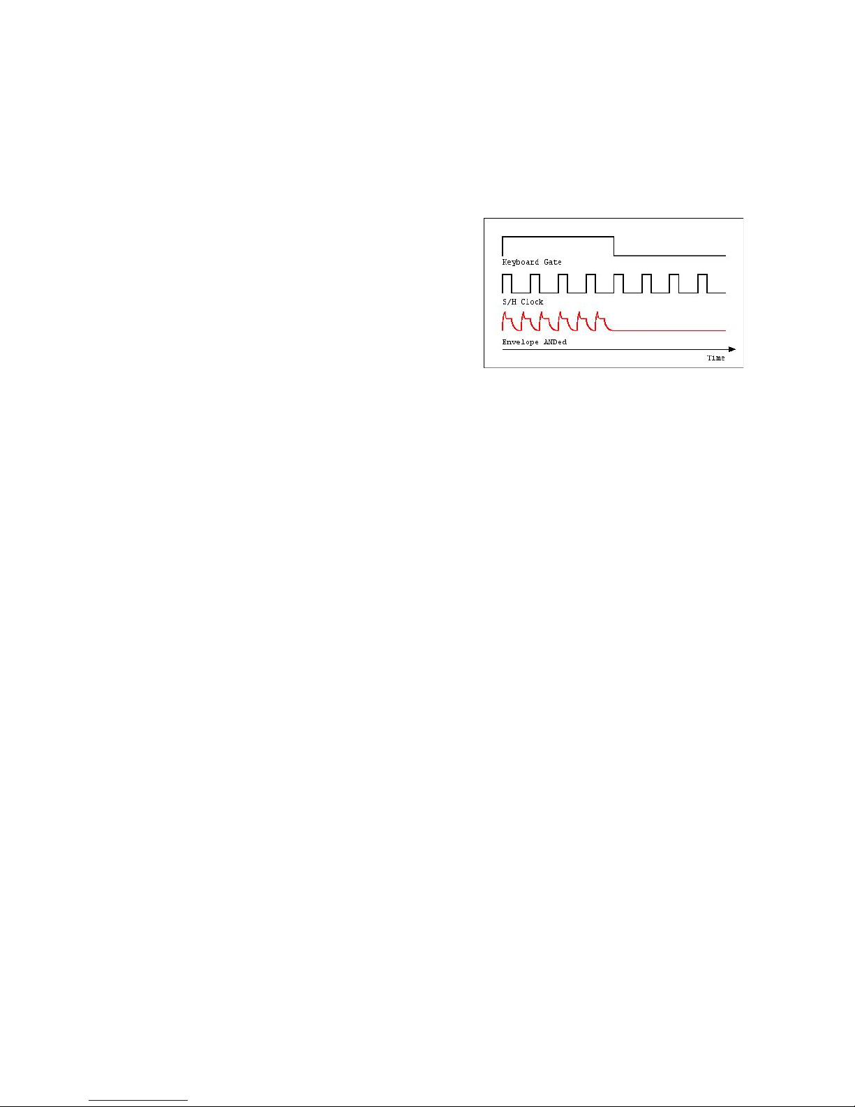
• KYBD GATE ANDed ON/OFF: if on, the
envelopes are gated only when S&H Clock AND
Keyboard Gate are simultaneously on, e.g., you
should press a note on keyboard to obtain the
automatic repetitions of envelopes at S&H Clock
rate.
• INPUT SOURCE: the signal sampled into the S&H circuit; you can choose between: WHITE
NOISE, PINK NOISE, LOW NOISE, LFO 1, LFO 2, VCO 1, VCO 2, VCO 3, VCO 4, VCO 5,
VCO 6.
• (INPUT SOURCE) LEVEL: the gain for the signal to be sampled.
• GLIDE: is a LAG generator for smoothing the abrupt changes in S&H control out. If Glide is
full ccw, you get a plain stepped output, if Glide is full cw, you’ll get a smoothed output.
Noise Generator Controls:
• NOISE COLOUR: you can choose between White, Pink and Low Frequency Noise.
Page 47
Grp Synthesizer A8 User’s Manual V. 2.06 47
STEP SEQUENCER
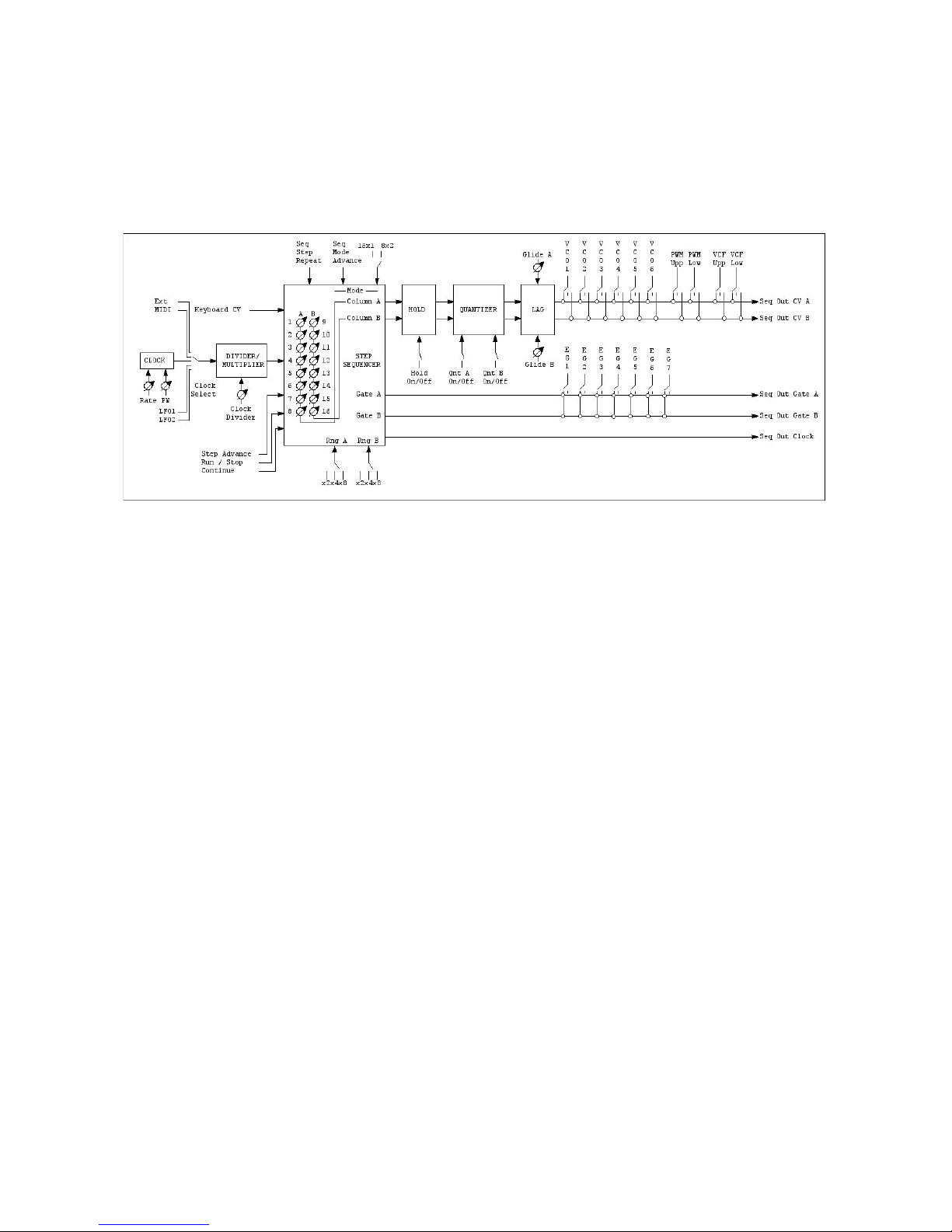
The A8 Synthesizer contains an integrated Step Sequencer that can be used either on Upper/Lower
internal sections or on external analog equipment.
The Step Sequencer has two Columns A and B, each one with 8 steps, that can be freely configured
for work in 8x2 parallel or 16x1 serial fashion; as standard, the Step Sequencer drives the Pitch of
VCOs and fires the EGs, but you can choose its outputs for drive (simoultaneously) the duty cycle of
square waves and the cutoff frequency of the filters. An fair array of clock sources (internal and
external) allows the multiplied/demultiplied synchronization of the Sequencer; moreover, there are
several advance step modes that, with the Repeat Step engine, leads to pretty complex strings of
values.
The behaviour of the Step Sequencer are organized in several stages, concerning: Clock and
Divide/Multiply Parameters, Advance and Repetitions Parameters, Sequencer Mode Parameters,
Column Parameters, Step Parameters, Assign Parameters.
Clock and Divider/Multiplier Parameters
The Step Sequencer can advance with its own internal Clock or can be drived by LFO 1/LFO2 from
Upper/Lower synth sections; still, is it possible to convert MIDI Clock and external TTL Pulse Clock.
You can decide the dividing/multiplying factor with all the clock sources; e.g., you can define how
many steps will be played on every clock impulse (multiply) or how many clock impulse will be
needed for advance one single step (divide).
Advance and Repetitions Parameters
As default, the Step Sequencer plays all the available steps in pretty standard forward motion (from
first till the last), moreover, is possible to select seven advance modes (forward, backward, forth and
back, pendulum, alternate columns, random, gate) that can always synchronized to the selected Clock
Source. Still, you can define how many simple repetitions (no repts, 2, 3 or 4 repts) should be
executed before to advance to the next step and you can define three different repetition patterns
(more on this later).
Sequencer Mode Parameters
As told before, the two columns of the Step Sequencer can be used in parallel mode (acting like a
8x2 sequencer) or in serial mode (acting like a 16x1 sequencer); in both cases, you can freely define
the lenght - e.g.: the number of active steps - for each column. In this way, it’s easy to obtain non
Page 48

Grp Synthesizer A8 User’s Manual V. 2.06 48
symmetrical patterns or whatever. The Step Sequencer can act in Loop Mode or, alternatively, in One
Shot Mode; the looping capability can be externally controlled thru a dedicated analog connection.
If you had previously experiences with analog step sequencer, you’ll probably aware of the potentially
dangerous interaction between long release times and paused steps into the sequencer: in order to
avoid any possibile yodeling on the CV output, the A8 Step Sequencer has a selectable Hold mode
that can be used for latch (e.g.: for freeze) the CV value contained in the last active step, prolonging it
over all the subsequently paused (e.g.: with no Gate Out enabled) steps. In this way, you’ll can
program patterns with dotted and paused notes of rock-solid CV values.
Column Parameters
Each column (A and B) of the Step Sequencer is equipped with an adjustable LAG Generator, for
Glide between step values, and a selectable Quantizer; the latter can round up every CV output to
the nearest 1/12 V, that is the nearest equal tempered semitone. Still, each column can be scaled for
span into three separate CV ranges: 0-2V, 0-4V, 0-8V; in all three cases, the maximum value is always
at clockwise position of the step potentiometer.
Step Parameters
Each of the 16 available steps (you can choose whatever number of steps you need) has a set of
individual parameters. The most obvious is the Step Value itself, e.g. the CV programmed with the
step potentiometer and emitted from the column output; but for each step there is a couple of
three-position switches related to: Gate Assign (step Gate assigned to Upper synth section, no Gate
out, Lower Synth section) and Step Behaviour (Normal step, Skip step, End Step). With the latter
switch, you can define if the step will be normally exected, or if it will be skipped/ignored during
playing pattern, or if it will be the last available step for the column/sequencer pattern. If you need a
4-step pattern, in the fourth step put this switch in End position.
Assign Parameters
While the Step Sequencer is fully equipped with output connections for drive external analog
instruments and input connections to be externally controlled, it is also well connected with the
internal synth structure of the A8.
You can choose, individually which VCO will be drived by the Step Sequencer and from what Column
A or B; furthermore, you can route Column A, B or A+B (in 16x1 Seq Mode) to the Pulse Width
control or the Cutoff Frequency control. In both latter cases, you can route sequencer control to
Upper or Lower synth section of the instrument.
Page 49
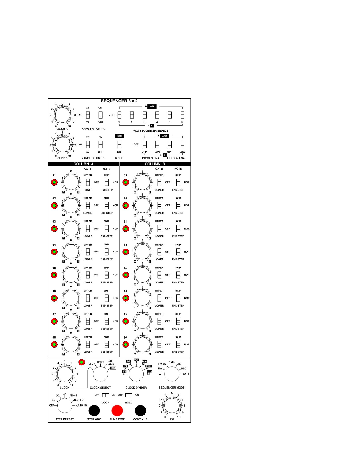
Grp Synthesizer A8 User’s Manual V. 2.06 49
STEP SEQUENCER REFERENCE
For sake of simplicity, the description of the parameters follows their physical location on the front
panel, from high left to low right. You can cross control the reference informations with the previously
written pages.
Integration, Quantization, Range and
Assign Section
In the upper part of the sequencer panel,
you’ll find those controls:
• MODE: selection of 16x1 or 8x2
behaviour of the Step Sequencer.
You can choose betwee 16 steps on
2 columns in series or 8 + 8 steps
from 2 columns in parallel. As a rule
of thumb, when you are in 16x1
mode, you’ll should follow the
control labels written in inverse
colour.
• GLIDE A: the glide time for CVs
outputted from Column A.
• GLIDE B: same as above, for
Column B.
• RANGE A: you can select the
CV amount for each column:
• x2: standard range for each step,
2V min-max, 0V full
counterclockwise.
• x4: double range for each step, 4
V min-max, 0V as above.
• x8: quadruple range for each
step, 8V min-max, 0V as above.
• RANGE B: same as above, for
Column B.
• QUANTIZER A: you can quantize
the CV Out from Column A on the
nearest semitone (1/12V).
• QUANTIZER B: same as above for
Column B.
VCO SEQUENCER ENABLE
Each VCO can be assigned to Column A,
Column B, Off (no sequencer enable) thru a
dedicated three-position switch:
Page 50

Grp Synthesizer A8 User’s Manual V. 2.06 50
• Position Up B/A+B (inverted label):
o if the MODE switch is on 8x2, this position assigns the VCO to Column B only;
o if the MODE switch is on 16x1, this position assigns the VCO to Column A and
Column B.
• Position Centre OFF: the VCO is free from Step Sequencer; you can drive it thru MIDI In port
or analog CV in.
• Position Down A/A (inverted label):
o If the MODE switch is on 8x2, this position assigns the VCO to Column A only;
o If the MODE switch is on the 16x1, this position assigns the VCO to Column A only;
same as above.
PW SEQ ENA(BLE)
You can assign the Upper and/or Lower VCOs Pulse Width Modulation to the columns of the Step
Sequencer.
Note
In each VCOs, you can dial the desired amount of PWM thru the PWM SOURCE Selector (SEQ position) and (PWM
SOURCE) AMOUNT.
(PW SEQ ENA) UPP:
• A/A+B (inverted label):
o if the MODE switch is on 8x2, this position assigns the PWM to Column A only;
o if the MODE switch is on 16x1, this position assigns the PWM to Column A+B in
series.
• OFF: the PWM of the Upper VCOs is free from Step Sequencer.
• B/B (inverted label):
o if the MODE switch is on 8x2, this position assigns the PWM to Column B only;
o if the MODE switch is on 16x1, this position assigns the PWM to Column B only;
same as above.
(PW SEQ ENA) LOW
Same as above, for the VCOs PWM of the Lower part.
F(I)LT(ER) SEQ ENA(BLE)
You can assign the Upper and/or Lower VCFs Cutoff Frequencies to the columns of the Step
Sequencer.
Note
This modulation affects both 24 dB and 12 dB on each Upper and Lower part. You can adjust the amount of modulation
with the AMOUNT 24 dB/12 dB and the switch KEY VEL/SEQ in the upper position.
(FLT SEQ ENA) UPP:
• A/A+B (inverted label):
o if the MODE switch is on 8x2, this position assigns the Cutoff Frequency to Column A
only;
o if the MODE switch is on 16x1, this position assigns the Frequency A+B in series.
• OFF: the Cutoff Frequencies of the Upper VCFs are free from Step Sequencer.
• B/B (inverted label):
o if the MODE switch is on 8x2, this position assigns the Cutoff Frequency to Column B
only;
Page 51

Grp Synthesizer A8 User’s Manual V. 2.06 51
o if the MODE switch is on 16x1, this position assigns the Cutoff Frequency to Column
B only; same as above.
Column A Section - Column B Section
As said before, each column has 8 indipendent step that can be freely programmed from the user;
each step has at disposal:
• LED: for visualize the selected step; red colour is for gate assigned to the envelopes of the
Upper or Lower synth section, blue colour is for gate unassigned. In the latter case, there is no
Gate output from the step.
• VALUE KNOB: the programmable CV; range adjustable with RANGE A/B switch.
• GATE SWITCH: three positions; as told before, corresponding to:
o UPPER: the Gate Out of the step is assigned to Upper part EGs;
o OFF: no Gate Out on the step;
o LOWER: the Gate Out of the step is assigned to Lower part EGs.
• NOTE SWITCH: three position:
o SKIP: the step is skipped;
o NORM: normal behaviour for the step;
o END STEP: sets the last played step for the sequence: if you need a 4-step sequence,
the fourth step has to be End Step mode enabled.
Clock & Clock Divider
You can define the (internal) clock rate, the clock source and the dividing/multiplying coefficient for
the selected pulse train. The available controls are:
• CLOCK: sets the speed for the Step Sequencer; range: 0.2-250 Hz.
• LED: flash at current speed.
• CLOCK SELECT: you can choose between different sources:
o INT: internal clock;
o LFO 1: the Step Sequencer plays at the VC LFO 1 frequency;
o LFO 2: the Step Sequencer plays at the VC LFO 2 frequency;
o EXT CLOCK: the Step Sequencer will advance with the pulse train events received at
the EXT CLOCK analog in port;
o MIDI (inverted label): the Step Sequencer will follow the MIDI Clock commands.
Note
Whatever source you choose, this will be processed thru the panel CLOCK DIVIDER (see below). The only exception is
when the Step Sequencer is (freely) driven from the Keyboard Gate.
• CLOCK DIVIDER: this section sets the divider/multiplier for all the possible Clock Sources
(except when the SEQUENCER MODE is in GATE position - see below); in this way, you can
decide how many clocks corresponds to one step advance or how many steps corresponds to
one clock impulse. Keep in mind that you can easily reach an over busy working condition for
the Sequencer. If so, reduce back the global speed and try to re-adjust the PW control. The
options available are:
o /8 /4 /2 0 x2 x4 x8: the dividing/multiplying positions for analog clock sources (all
except MIDI); at central 0 position, the Divider is bypassed; at /2 position, the Step
Page 52
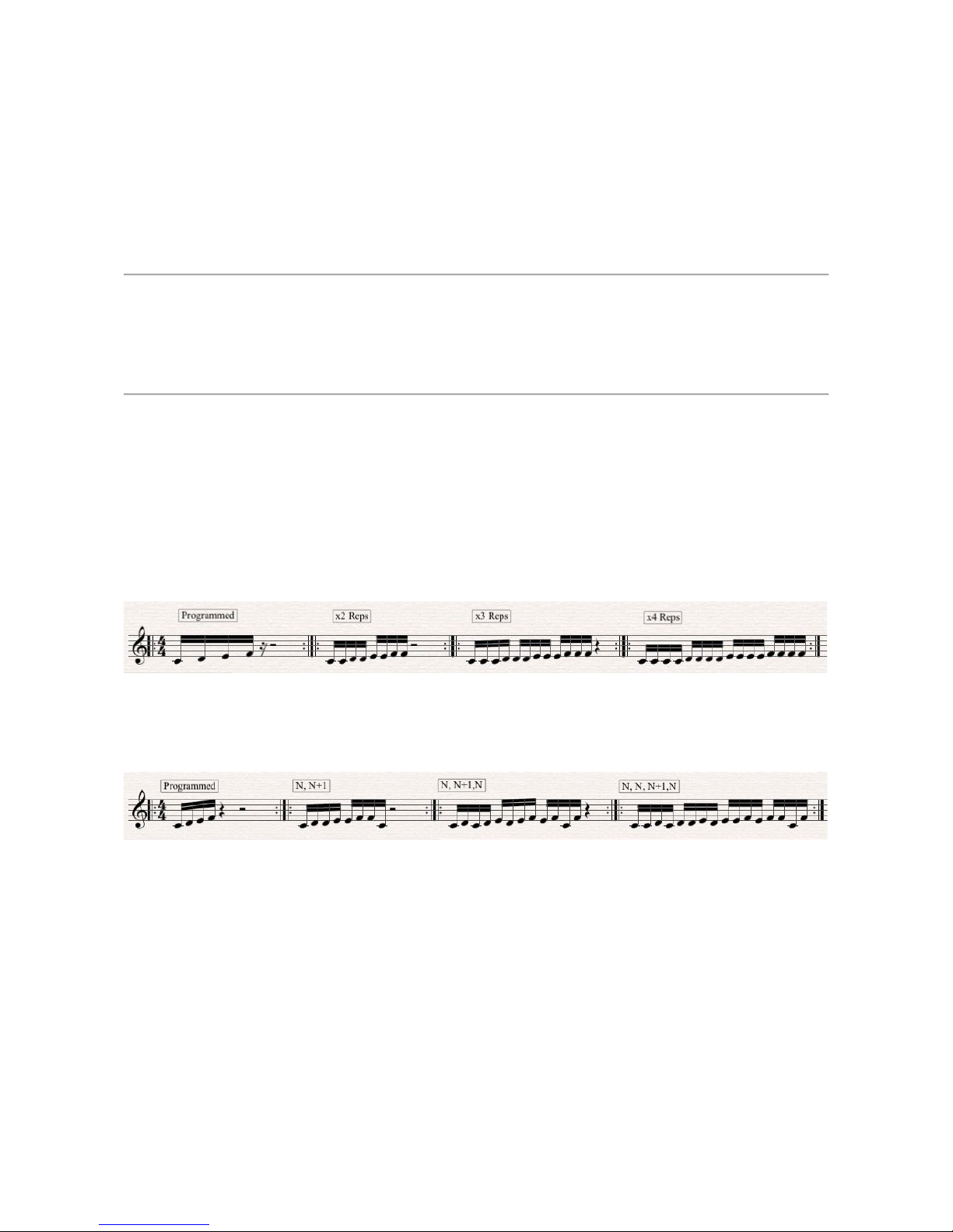
Grp Synthesizer A8 User’s Manual V. 2.06 52
Sequencer will advance one position on every two clock pulses; at /4 position, you’ll
need four clock pulses for advance one position; at x2 position, the Step Sequencer will
advance two positions on every one clock pulse; at x4 position, the Step Sequencer will
advance four positions on every one clock pulse, and so on…
o 1/1 1/4 1/8 1/8T 1/16 1/16T 1/32 (in inverse labeling): the dividing/multiplying positions
for MIDI Clock. You can choose the rhythmical advance ratio (e.g.: one step on every
4/4 bar, on 1/4 note, on 1/8 note and so on…).
Note
This warning is valid only when the Clock Source is External, LFO 1 or LFO 2, so beware. Due to a peculiar behaviour of
the internal clock dividing network, if you want to drive the sequencer in a “one per one” relationship with clock source
EXT, LFO 1 or LFO 2 (e.g.; one clock event will advance one step into the sequencer), you should put the CLOCK
DIVIDER selector on the X8 position. The other positions are still active, but in a “divide only” way ([X4]= divided by 2,
[X2] = divided by 4, [0] = divided by 8, [/2] = divided by16, [/4] = divided by 32, [/8] = divided by 64)
Step Repeat & Loop
The Step Sequencer can prolong the duration of the sequence with several repetitions algorithms.
• STEP REPEAT: you can choose between different step advance ratios:
o OFF: no step repetition, normal behaviour;
o x2: each step plays twice before advance in the sequence;
o x3: each step plays three times;
o x4: each step plays four times.
o N,N+1: the sequencer plays steps 1, 2, 2, 3, 3, 4, 5, 5, 6…
o N,N+1,N: the sequencer plays steps 1, 2, 1, 2, 3, 2, 3, 4, 3…
o N,N,N+1,N: the sequencer plays steps 1, 1, 2, 1, 2, 2, 3, 2, 3, 3, 4, 3, 4, 4, 5, 4…
• LOOP On/Off: sets the loop condition for the Step Sequencer.
• HOLD On/Off: if you are using two (or more) adiacent steps with different Gate assign (e.g.:
the first on, the second off) on a synth setting with a long EG release time, you’ll probably hear
during the release stage the off-step CV still driving the VCOs. In modular synthesis, the only
way to avoid this is the insertion of some kind of latch mechanism on the CV output of the
sequencer (e.g.: a S&H module or similar). Into the A8 Step Sequencer, you can freeze or
prolong the CV value from Gate-active step over all the subsequent Gate-inactive steps.
Obviously, this behaviour is verifable only if your release(s) time are long enough.
• PW: sets the duty cycle for the sequencer internal clock; you can choose between different
PW ratios, e.g.: different degrees of staccato/legato step percentage.
Page 53
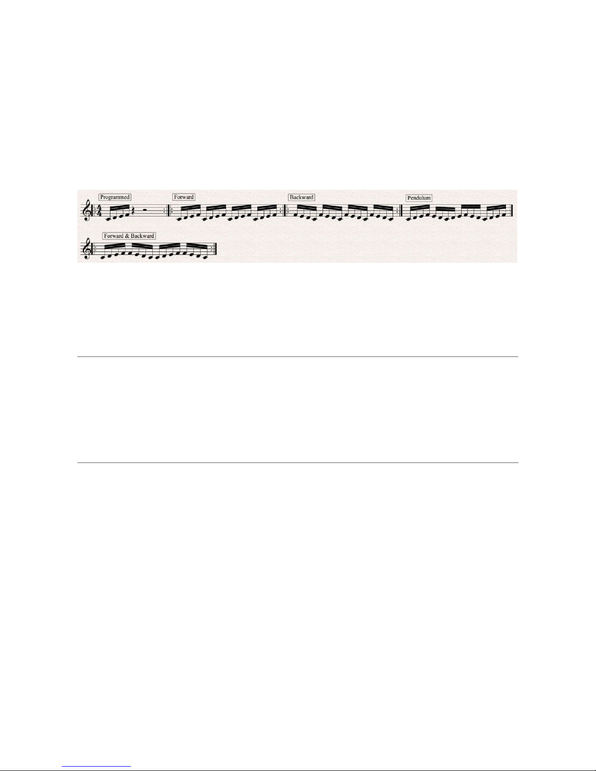
Grp Synthesizer A8 User’s Manual V. 2.06 53
Sequencer mode
With this selector, you can choose one of the possibile playing direction(s) for the Step Sequencer.
• SEQUENCER MODE: you can choose between:
o FW: forward motion 1-8;
o BW: backward motion 8-1;
o FW/BW: forward & backward mode 1-8-1; terminal notes are repeated;
o PNDL: forward & backward mode 1-8,8-1,1-8; terminal notes are not repeated.
o ALT: Step Sequencer plays steps 1, 9, 2, 10, 3, 11… e.g.: it alternates steps from two
Columns A & B;
o RND: random motion;
o GATE: Step Sequencer advance and prolongs one step on each MIDI/CV keyboard
note.
Note
Don’t forget that you can freely combine the Repetitions, Sequencer Modes and different Columns Step numbers for
obtain pretty wild sequenced patterns.
There is a subtile difference between External Clock Advance and Gate Mode Advance: the former takes for granted that
the pulse train will be rhythmically constant and equally spaced (e.g.; the steps of externally driven sequencence will be all
equal in lenght and rhythm); with the latter option, you can advance step only when you fire Gate On (e.g.: when you
press a key) on the MIDI/Analog keyboard. In this way, you can create different rhythms for steps and, best of all, you can
indefinitely prolong the step duration with Gate On.
Manual controls
The three following front panel manual controls are doubled as analog input for external controls:
• STEP ADV(ANCE): each press on the button will advance one step in the sequencer; the
control is ORed with the analog STEP ADV IN on the front panel (see below);
• RUN/STOP: each press on the button will put the Step Sequencer in Play or Stop mode; the
control interacts with the analog RUN/STOP in port on the front panel (see below); the
Sequencer will start from the first active step;
• CONTINUE: restart the Step Sequencer from the next step after the last played.
Sequencer remote connections and controls on the front panel
As reported above, we’ll (re)list all the available connections and external controls for Step
Sequencer.
• GATE OUT COLUMN A - COLUMN A+B - COLUMN B: the Gate Output for the single
Column A or B and for the two Columns A+B combined in series (16x1 steps). Range:
0/+5V.
Page 54

Grp Synthesizer A8 User’s Manual V. 2.06 54
• CV OUT COLUMN A - COLUMN A+B - COLUMN B: the CV Out for the separate
Column A or B (8x2 steps) and for the two Columns combined in series. Range: 0/+8V.
• STEP ADVANCE: on each switch closure received at this port, the Step Sequencer advance
one step.
• RUN/STOP: each switch closure received will alternate between Run and Stop. This external
input will interact with the front panel control RUN/STOP. The Step Sequencer will restart
from step no. 1.
• CONTINUE: the switch closure received at this port will put the Sequencer in playback from
the last step played without resetting to step no. 1.
• EXT CLOCK: a train of pulse (0/+5V) received at this port will advance the Step Sequencer; it
will function only if the Step Sequencer is set to EXTERNAL CLOCK SELECT position.
• LOOP: the change of status from a footpedal toggle switch connected on this port will enable
the LOOP ON MODE for Step Sequencer. This external input is parallel with the hardware
LOOP SWITCH on the front panel.
Note
If you want to remotely control LOOP ON, don’t forget to turn off its hardware switch on the front panel.
Page 55

Grp Synthesizer A8 User’s Manual V. 2.06 55
© ® 2010
Manual: Enrico Cosimi
Grp Synthesizer
di Iannotti Rossana
Via Formello, 17 - 00040 Monteporzio Catone (RM)
P.IVA 10681631007
Page 56

Grp Synthesizer A8 User’s Manual V. 2.06 56
 Loading...