

Page 1
Rev. 3.0
www.grozonecontrol.com
USER GUIDE
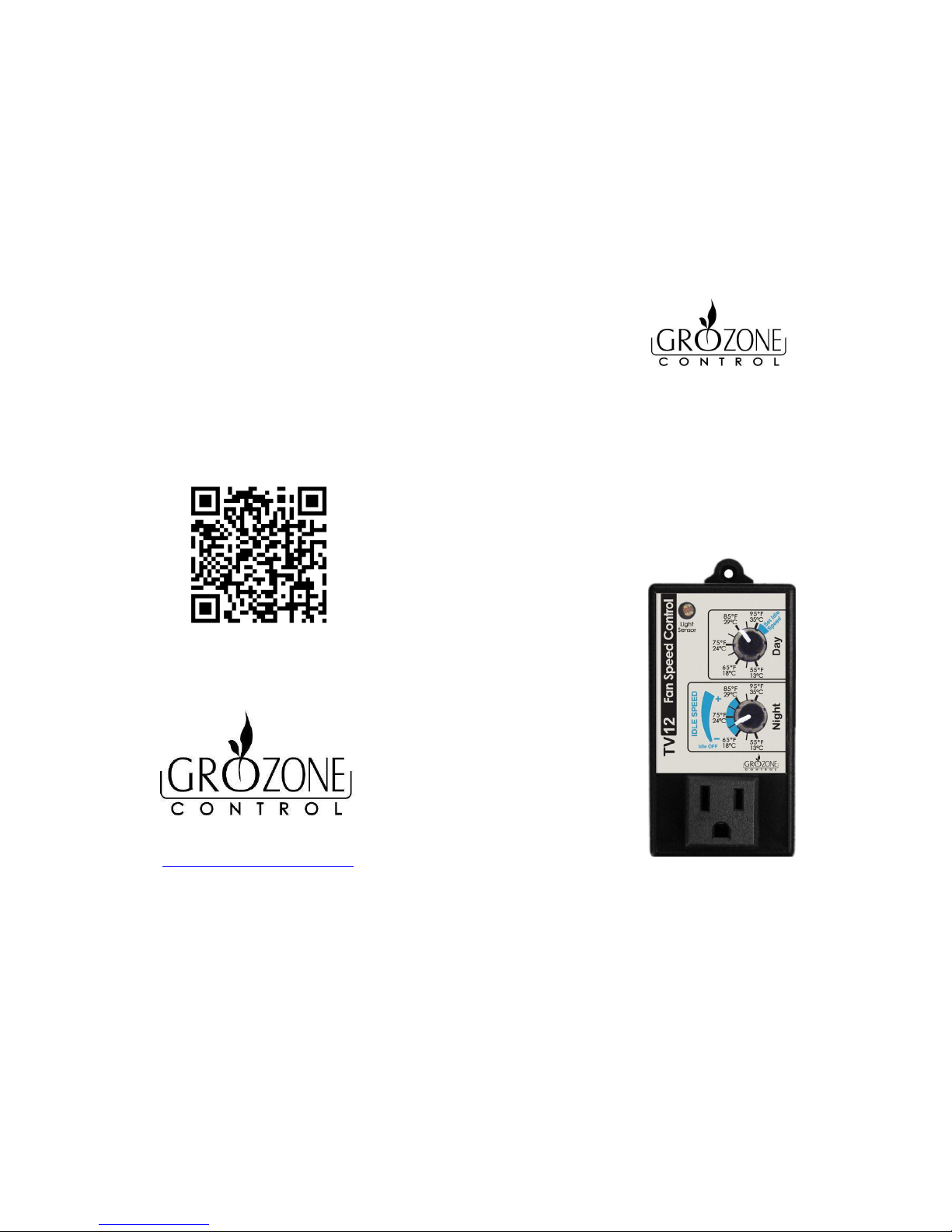
TV12
Day & Night Fan Speed Control with Idle
Setting
Page 2
TABLE OF CONTENTS
SAFETY NOTICE ........................................................................................... 1
PRODUCT DETAILS ...................... ............................................ .................... 2
INSTALLATION .......... .................................................................................. 3
SETTINGS .................................................................................................... 4
SETTINGS .................................................................................................... 5
COMPLETE TROUBLESHOOTING GUIDE ....................... ................................. 6
COMPLETE TROUBLESHOOTING GUIDE ....................... ................................. 7
COMPLETE TROUBLESHOOTING GUIDE ....................... ................................. 8
WARRANTY & CUSTOMER SERVICE .............................................................. 9
2 I’ve been through the troubleshooting steps, what do I do if I meet
a problem at any of these steps? Is my product covered by the
WARRANTY?
• Grozone controllers are covered by a 3-year warranty (*). We will
replace any DAMAGED PRODUCT WITH A BRAND NEW PRODUCT.
• Covered or not covered? We do not authorize the replacement of
fully working products nor altered (tampered) products. The
Troubleshooting steps will help you identify a damaged product. Do
not hesitate to contact us or contact your retailer to make sure the
controller is not fully working or damaged before returning it to the
store.
• My product is not fully working or damaged, I want a replacement
unit: in order to get a replacement product, you MUST return all
modules and applicable accessories to the retailer. To avoid being
charged for the accessories, be sure to include all pieces. Thanks for
your cooperation.
• Any Grozone Control product that is returned with obvious signs of
user neglect will not be covered by the warranty. Grozone Control
exercises the right to make final decisions in these matters.
(*)
The warranty period begins from the date of purchase at the retail level.
The retailer/consumer must keep their proof of sale/purchase. Otherwise,
Grozone Control will consider the manufacturing date to apply the warranty
coverage.
IMPORTANT MESSAGE TO RETAILERS
Retailers must call Grozone Control to get authorisation to replace the
defective product and a RMA number.
1-855-262-1800
.
NOTE
10
Page 3
WARRANTY & CUSTOMER SERVICE
DO YOU HAVE A PROBLEM WITH YOUR CONTROLLER? PLEASE READ
THESE INSTRUCTIONS CAREFULLY AND SAVE THEM FOR FUTURE
REFERENCE
1. I think my controller is damaged, or it simply does not work as
indicated in the user guide, what should I do?
• Please refer to the troubleshooting steps. Follow these instructions
carefully, step by step. The controller should work as described in
the “Expected results” column of the Complete Troubleshooting
Guide.
Do you need assistance on executing the Troubleshooting steps?
1. Contact us at 1-855-262-1800
2. Send us an EMAIL at [email protected]
3. VISIT our Technical Support Center at www.grozonecontrol.com
Technical Support is available Monday through Friday, from 8:00 AM to
8:00 PM, Eastern Time.
9
SAFETY NOTICE
IMPORTANT SAFETY INSTRUCTIONS
SAVE THESE INSTRUCTIONS
DANGER
TO REDUCE THE RISK OF FIRE OR ELECTRIC SHOCK,
CAREFULLY FOLLOW THESE INSTRUCTIONS.
To reduce the risk of electric shock, disconnect power to the 120V
electrical outlet before installing or removing the unit. When removing
the electrical wall plate, it may fall across plug pins or become
displaced.
To reduce the risk of electric shock, this product has a grounding type
plug that has a third (grounding) pin. This plug will only fit into a
grounding type power outlet. If the plug does not fit into the outlet,
contact a qualified electrician to install the proper outlet. Do not
change the plug in any way.
1
Page 4
PRODUCT DETAILS
Operation and Specifications
Temperature setpoint between 55°F and 95°F / 13°C to 35°C.
The 120V output is variable. Max 750 Watts, 6.2 Amps.
User may select the minimum fan speed (Idle Speed) between 25% and
60% of full power.
2 seconds «KickStart» at startup. (100% power to improve or ensure fan
startup).
Low temperature limit 10°F below setpoint
6-ft temperature probe works from +32°F to +212°F (0°C to 100°C).
Electrical Specifications: See the rating label on your product.
2
COMPLETE TROUBLESHOOTING GUIDE
STEP HANDLING AND TEST DESCRIPTION EXPECTED RESULTS
8
• Turn UPPER knob fully CW (Set
Idle Speed)
• In the blue section, turn LOWER
knob from top to bottom.
The fan speed will slow
down.
9
• Turn LOWER knob fully CCW
(55°F).
The fan will turn OFF.
10
• Slowly turn the lower knob CW
towards the blue zone until the
fan turns on.
The fan will turn ON at
full speed for 3
seconds (kickstart)
then the fan speed will
slow down.
8
Page 5
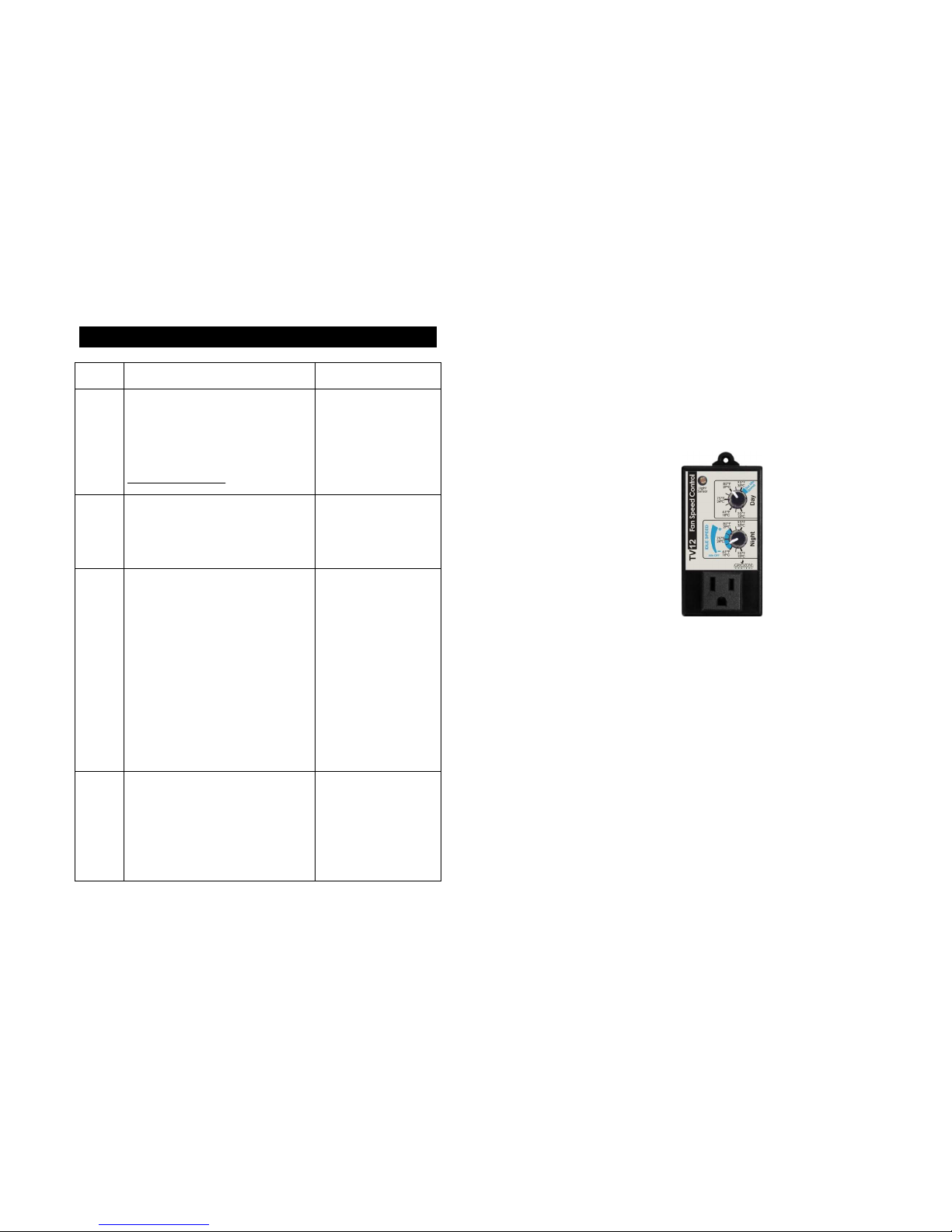
COMPLETE TROUBLESHOOTING GUIDE
STEP HANDLING AND TEST DESCRIPTION EXPECTED RESULTS
4
•
Turn LOWER knob fully CCW
(55°F).
• Cover the Light Sensor
completely with hand palm or
black electrical tape (a single
finger will NOT cover the sensor
appropriately).
The fan will turn ON
after 6-8 seconds.
5
• Maintain the light sensor covered
while turning the LOWER knob
fully CW (95°F).
The fan will turn OFF.
6
• Uncover the light sensor and wait
for 6-8 seconds. Then, rotate the
UPPER knob very slowly CCW
until the fan turns ON.
The fan will turn ON
when the knob pointer
(line) indicates a
temperature level
similar to the ambient
room temperature
(e.g. if the knob line
indicates 75° when the
fan turns ON, the
ambient temperature
should be around
77°F).
7
• Warm up temp probe in your
hands.
The fan will speed up
to full power.
7
INSTALLATION
Note: Designed for single phase 120VAC induction motor fans up to
750 Watts.
Plug into 120 VAC outlet (see security notice on page 1).
Place the sensor at desired location.
Connect the fan into the front panel outlet (MAX 750W, 6.2A).
Note: For multiple fan application, use a power bar.
Installation is now complete
Photocell
3
Page 6
SETTINGS
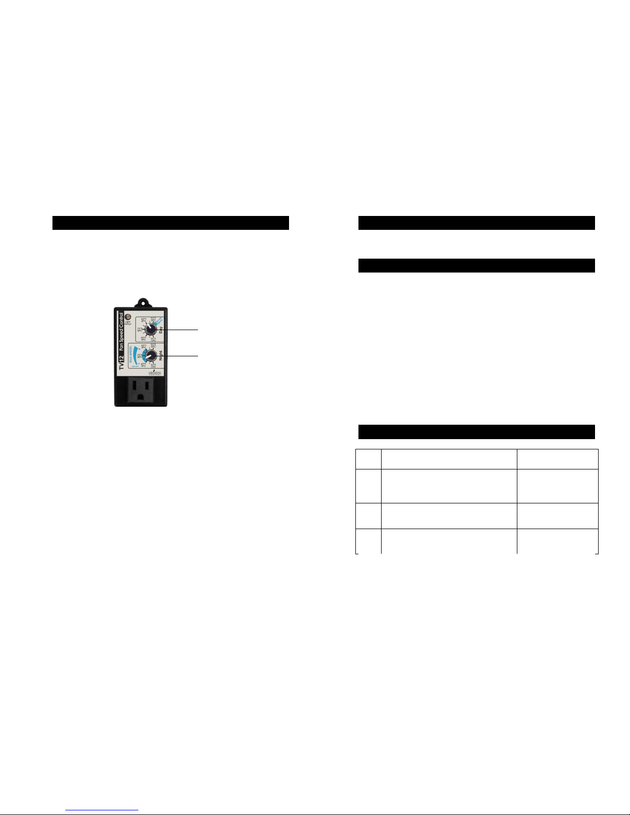
IDLE MODE & SPEED SETTINGS
Turn upper knob
clockwise to ‘’Set Idle
Speed’’
Set Idle speed
(25%
to 60% of full power)
4
COMPLETE TROUBLESHOOTING GUIDE
Day & Night Fan Speed Control
TV12
1 – Before you start
***IMPORTANT: READ AND FOLLOW THESE INSTRUCTIONS BEFORE
STARTING THE TEST.
• DO NOT CONNECT THE UNIT BEFORE STEP 1 OF THE TEST.
• CONNECT A FAN IN THE FRONT UNIT OUTPUT.
• LIGHTING CONDITION: perform this test in a room with enough light
for the controller to detect a DAY condition.
• TEMPERATURE: perform this test in a room where ambient
temperature is between 65°F and 85°F (18°C and 30°C).
• Definitions : CW : Clockwise.
CCW : Counterclockwise.
2 – Test
STEP HANDLING AND TEST DESCRIPTION EXPECTED RESULTS
1
• Plug the unit into the power outlet.
• Turn UPPER and LOWER knob fully
CCW (55°F).
The fan will turn ON.
2
• Turn LOWER knob to 95°F.
The fan stays ON.
3
• Turn UPPER knob fully CW (95°F).
The fan will turn OFF.
6
Page 7
SETTINGS
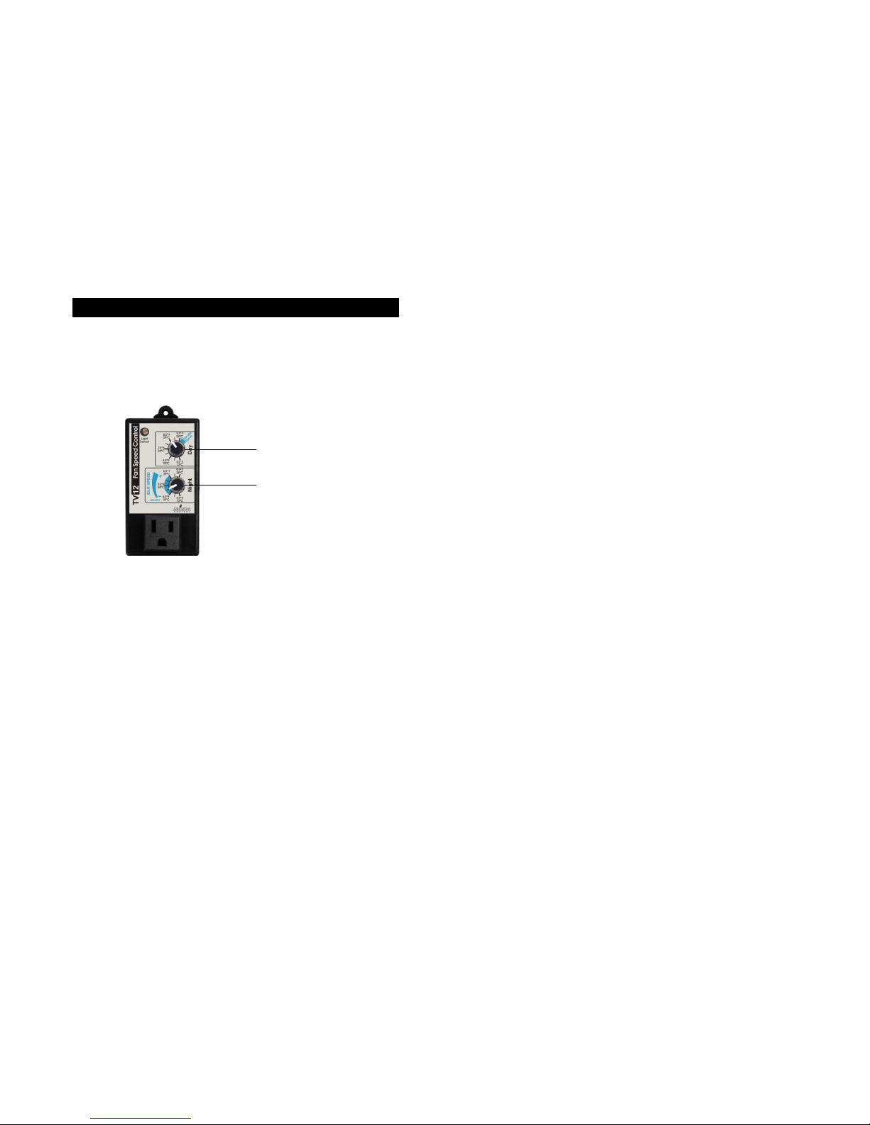
ADJUSTING TEMPERATURE SETPOINTS
Set Day Temperature
setpoint
Set Night Temperature
Setpoint
5
 Loading...