

INSTRUCTION MANUAL S1230, Rev D
Air Operated Grease Ratio Pumps 50:1
GP1, GP2, GP3
Congratulations on purchase of this World Class Air Operated Grease Ratio Pump !
• World-class Industrial High Pressure Grease pump with guaranteed performance & hassle free operation
• Pump dispenses Grease at pressures upto 50 times the Air inlet pressure
• Designed to work in tough conditions- Ideal for use in Industry, workshop, farm, construction or as part of the Mobile Grease system
• All metal construction, fully CNC machined with hardened wear resistant moving parts
• Reciprocating piston operated 2.5” (63 mm) dia. Air Motor
• Fitted with strainer at suction tube inlet for clean grease to the bearing
• Supplied in two choices :-
- Pump Only
- Pump with Drum Cover, Rubber Lined Follower Plate, High Pressure Grease Hose, Z swivel & Professional Grease Control Valve
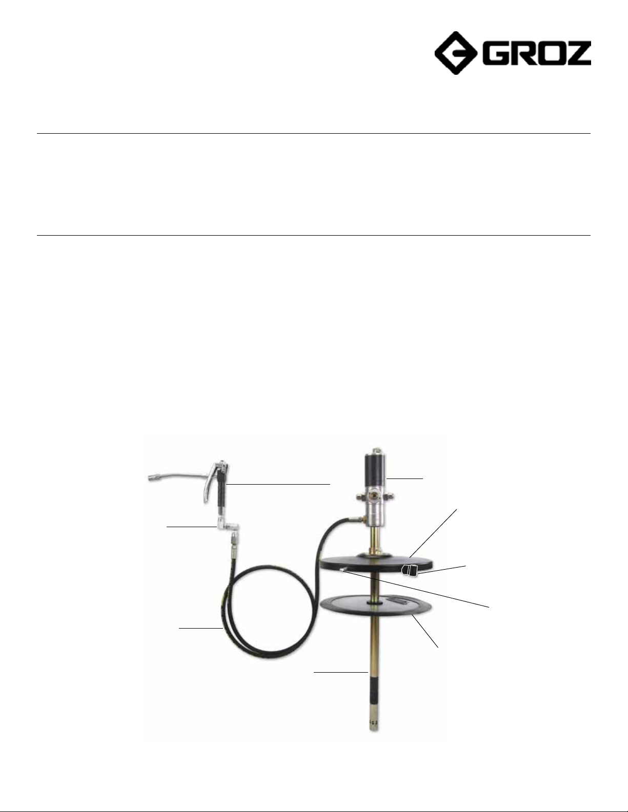
Z Swivel
High Pressure Rubber Hose
Grease Control Valve
Suction Tube
Fig.1
Air Motor Assembly
Drum Cover
Nozzle Holder
Cover Screws
Follower Plate
1

Contents Page No.
PUMP CONSTITUENTS ..................................................................................................
PUMP CONSTRUCTION .................................................................................................
WORKING OF PUMP .....................................................................................................
INSTALLATION ...............................................................................................................
PUMP OPERATION .........................................................................................................
MAINTENANCE & REPAIR .............................................................................................
• Pumping Section Kit Replacement ............................................................................
• Drive Section Kit Replacement. ................................................................................
EXPLODED VIEW ............................................................................................................
3
3
4
5
6
7-11
7-8
9-11
12
PARTS LIST .....................................................................................................................
TROUBLESHOOTING ........................................................................................................
REPLACEMENT & SERVICE PARTS PROGRAM FOR GREASE RATIO PUMP .................
• Replacement Parts Program .....................................................................................
• Service Parts Program (Pumping Section Kit - KIT/BTM/RP-G) ...............................
• Service Parts Program (Drive Section Kit - KIT/TP/RP-G) .........................................
SPECIFICATIONS ............................................................................................................
WARNINGS ....................................................................................................................
13-14
15
16-18
16
17
18
19
19
2
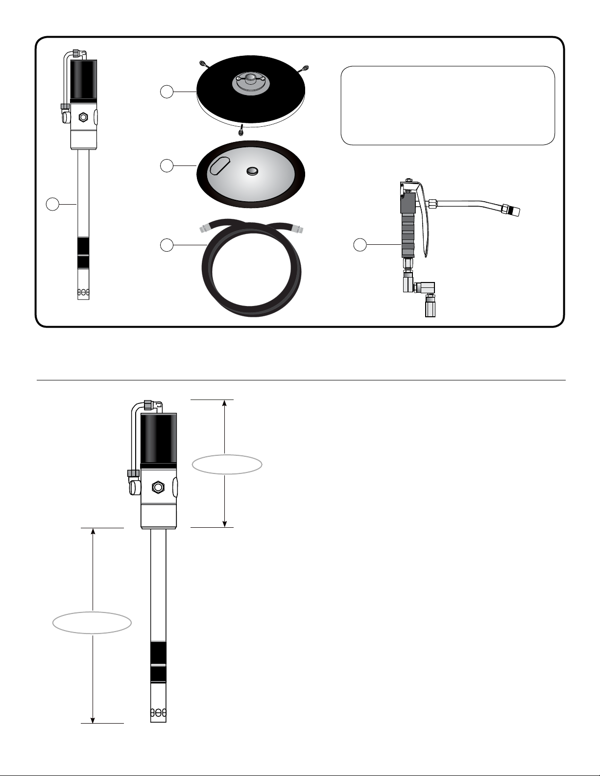
PUMP CONSTITUENTS
1. Grease Pump Assembly
2
3
1
2. Drum Cover with Thumb Screws
3. Rubber Lined Follower Plate
4. High pressure Rubber Hose
5. Professional Grease Control Valve with Z Swivel
Fig. 2
PUMP CONSTRUCTION
4
Fig. 3
Drive Section
The pump is made up of two sections as given below :-
• Drive section :- It consists of an Air Motor Assembly driven
• Pumping Section :- It consists of a pump in which a piston
5
by compressed air. The piston diameter of the air motor is
2.5” / 63 mm. The motor consists of an air cylinder with
piston and one reciprocal valve with a nylon slider. The valve
directs the compressed air alternately to the top or bottom
of the piston, thus producing a reciprocating motion of the
piston rod.
lifts the grease through Non Return Valves by reciprocating
inside the pump cylinder. The grease is discharged with
pressure (from the outlet located at bottom of Air Motor) into
the delivery hose.
Pumping Section
NOTE
AIR MOTOR of these pumps starts automatically when the
Grease Control Valve is opened. When the valve is closed, Air
Motor builds up a back-pressure and stops operating the pumping
section.
PRESSURE RATIO of the pump states the ratio of the output
grease pressure to the incoming air pressure. When the pressure
ratio is 50:1, we achieve an output grease pressure up to 7500 PSI
(500 BAR) when the incoming air pressure is 150 PSI (10 BAR ).
3
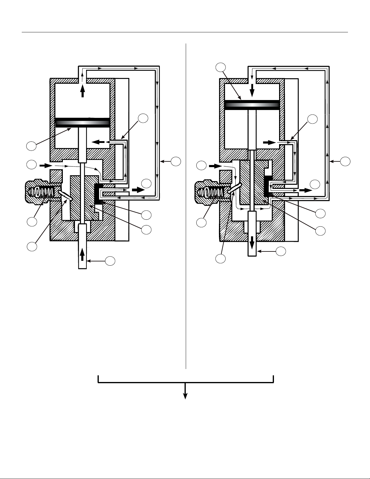
WORKING OF PUMP
UPSTROKE DOWNSTROKE
C
A
I
Fig. 4 Fig. 5
C
B
E
G
F
H
A
I
B
G
F
H
E
J
D
UPSTROKE -
When Grease Control Valve is opened, compressed air enters
at arrow A and passes through passage B to the underside of
the Piston C, driving the Piston C and Piston Rod D upwards.
The air above the Piston is evacuated through passage E,
past the Slider Valve F and out at arrow G.
The Piston approaches top dead centre and Piston Rod D
makes contact with the Slider Rod H. Now the Slider Rod H
starts moving up with the Piston Rod D.
The air motor repeats Upstroke & Downstroke in continuous cycle to produce a reciprocating motion, driven
by compressed air. This motion is transferred via a connecting rod to the piston in the Pumping Section.
During every upstroke, non return valves (with spring & ball check) get opened & the piston lifts the grease.
During every downstroke, non return valves get closed & the piston discharges grease from the outlet valve.
Closing the Grease Control Valve shuts off the air motor & pump stops dispensing grease.
D
J
DOWNSTROKE -
The incoming air is now led via passage E to the upper side
of Piston C, driving it and the Piston Rod D downwards.
The air under the Piston C is evacuated through passage B,
past the Slider Valve F and out at arrow G.
The Piston approaches bottom dead centre and Piston rod
D makes contact with the Slider Rod H. When Slider Rod H
passes its centre position, the Pusher Spring I and Pusher
Button J snap it over to its lower position.
4
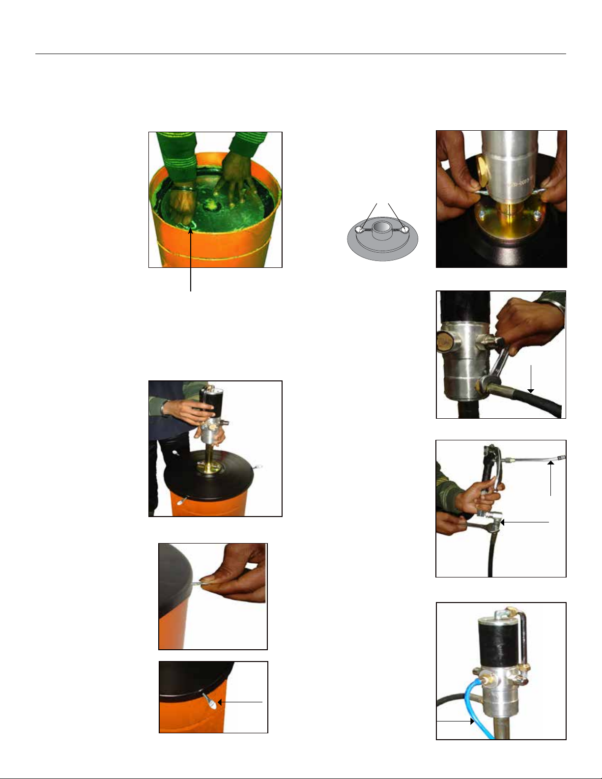
INSTALLATION
NOTE
An FRL (Filter-Regulator-Lubricator) unit must be used in the Air supply, before it is connected to the pump. Set the regulator to 6 BAR
(90 PSI) or any required inlet pressure, but never more than 150 PSI (10 BAR) or less than 30 PSI (2 BAR).
1. Fill the drum with
Grease leaving empty
space of about 2” from
the top rim. Shake the
drum after it is filled
to remove air pockets.
Place the follower
plate in the grease
drum with the
lift handle facing
upwards. Push the
follower plate down,
until some grease is
forced through the
centre hole on the
plate.
2. Place the drum cover
on the drum. Lift the
pump assembly &
slide the suction tube
through the drum
cover & centre hole in
the follower plate.
3. Push the pump
assembly down till
the bottom of the
pump touches the
base of the drum.
Adjust the drum cover
and tighten it with
the thumb screws
provided along with
the drum cover.
Lift Handle
4. Tighten the drum cover
with the pump suction
tube with the help of
thumb screws.
Thumb Screws
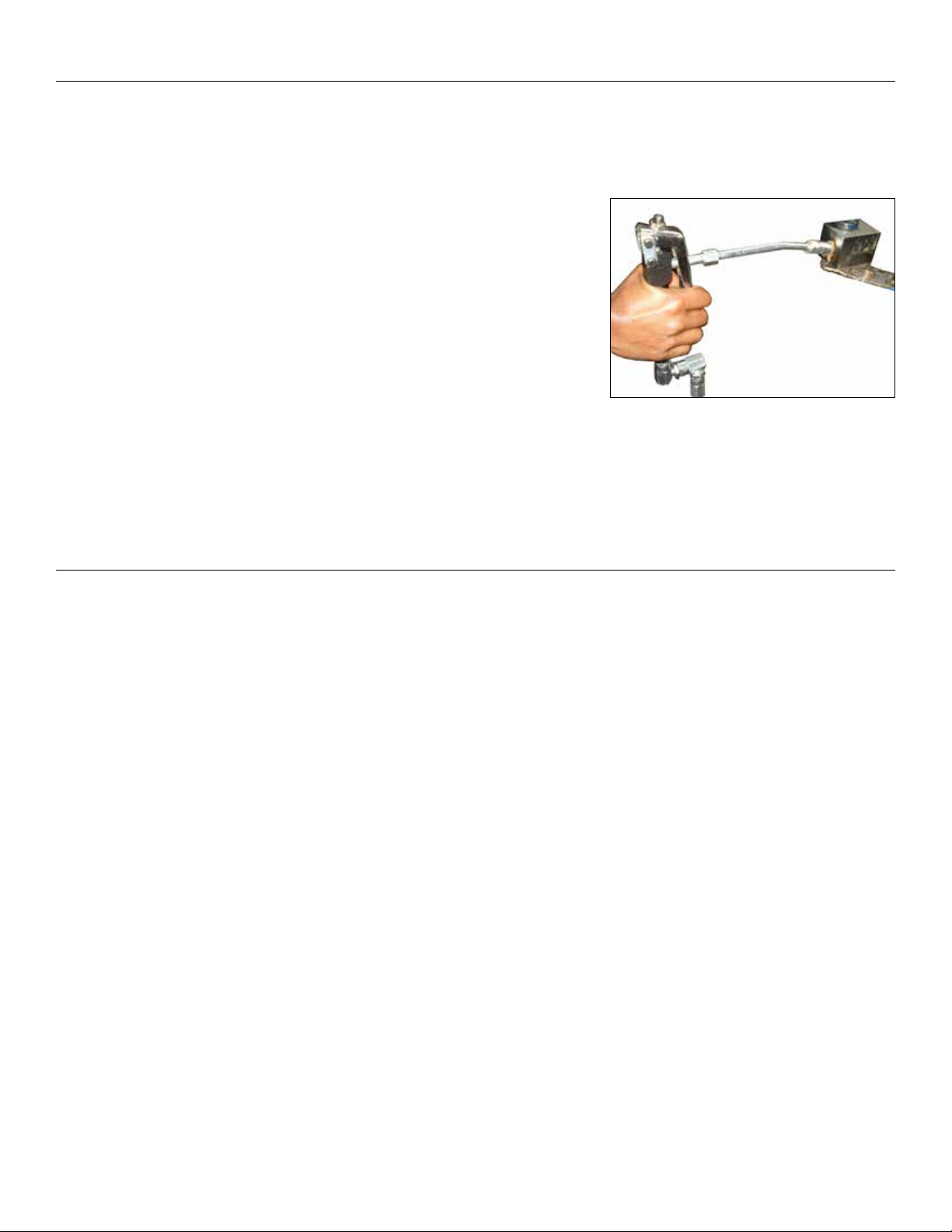
5. Use a wrench to tighten
high pressure hose to the
pump outlet.
6. Use a wrench to tighten
the other end of the hose
to Z Swivel of grease
control valve. Tighten the
outlet extension & coupler
to the control valve outlet.
Use thread sealant on all
connections to ensure
leak-proof working.
7. With the air supply turned
off, connect the Air line
into the air inlet on the
pump.
Hose
Extension
& Coupler
Z Swivel
Thumb
Screw
Air Line
5
PUMP OPERATION
1. Partially open the on/off air valve (It helps in creating initial vacuum when filling a totally dry pump). Pump will start operating
automatically until it gets primed. Pump is said to be Primed when grease is available at the pump outlet, making the pump ready to use.
Once primed, the air motor will stop. Open the on/off air valve fully.
2. Hold the grease control valve near a container & press the trigger. Pump will start
operating with continuous grease discharge as long as the trigger is pressed. Release
the trigger & this will stop the pump. Check for any leaks from any of the connections &
Tighten again if required.
3. Connect coupler fitted onto the control valve extension with the grease nipple & press trigger. Be careful not to over-lubricate as the pump
will keep dispensing grease as long as the trigger is pressed. Once the trigger is released, pump will stop dispensing grease & the air
motor will stop.
4. When not in use & at the end of each day, air supply to the pump must be switched off.
6

MAINTENANCE & REPAIR (Refer to Exploded View - Page 12)
Service Precautions
• Before performing any service operation, always shut off the air supply and release the pressure of the medium, i.e. let the grease out so
that the pressure decreases. When storing the pump assembly without the bucket, cover the Filter Tube (57) with Filter Cap (62).
• Be careful not to damage any parts when dismantling. While removing shafts which do not have key flats, use a Pipe wrench, Polygrip
wrench or the like. The easiest way to remove such a shaft is to grip it in a vice with aluminium or copper jaws, clamp the shaft in a
hand-drill chuck and then turn the chuck by hand.
• Be careful when fitting O-rings and seals. Always lubricate them with grease before fitting. They must never be threaded over sharp
edges when being fitted. Lubricate all moving parts with synthetic grease. Apply minor locking fluid on all threaded joints.
• When troubleshooting, be on a lookout for dirt in valves / ball seats, scratches in sealing surfaces & damaged O-rings / seals / gaskets.
Recommended Tools
Phillips Screwdriver
T- Handle
Size 10 mm
Adjustable Caliper Wrench
Combination Wrench
Size 10, 14, 21, 25, 28 & 32 mm
Pin Punch
2 mm
Tweezer
Pumping Section Kit Replacement (Refer to Table 5 - Page 17)
1. Hold Barrel (63) in a soft-
jaw vice. Pull out Filter
Cap (62) by hand.
3. Unscrew Top Coupler (52)
using wrench (size 28
mm) on the given flats.
Remove lower coupler
assembly.
1/2” Male Threaded Pipe
Ball Pein Hammer
Plastic Mallet
A Soft - Jaw vice
(Aluminum or Copper Jaws)
2. Unscrew Nyloc Nut (61)
using T-handle (size 10
mm) & also remove
Piston Washer (60) from
the end of Filter Tube
(57).
Nyloc Nut Piston Washer
Lower Coupler Assembly
4. Remove the outlet adapter
(35) using wrench (size 25
mm).
7

5. Tighten a 1/2” male
threaded pipe into the
outlet port & unscrew
Air Motor Assembly
anticlockwise. Carefully
remove Air Motor from
Barrel (63).
8. Hold Filter Tube (57) in
vice. Using two wrenches
(size 28 mm), hold Bottom
Coupler (54) & unscrew
Top Coupler (52). Remove
Slide Bush (53).
Slide Bush
6. Support Pump Cylinder
(51) on a V block &
insert a pin punch
vertically into the hole
of Pump Cylinder (51).
Tap lightly with a hammer
to drive out lower Slotted
Spring Pin (44) taking
care not to bend the
Extension Rod (46).
7. Unscrew Pump Cylinder
(51) & remove upper
Steel Ball (47) & Non
Return Spring (48).
9. Unscrew Bottom Coupler
(54) with wrench (size 28
mm) & remove Guide Bush
(56).
Guide Bush
10. Replace the Repair Kit (KIT/BTM/RPG) as mentioned in Table
5 - Page 17, by following the steps 1-9 in reverse order taking
care of the points below:
• Pump Cylinder (51) has a pin-hole
end that must face upwards;
towards Extension Rod (46).
Non return
Spring
Steel Ball
• Slide Bush (53) has a slotted end
that must always face upwards;
towards Top Coupler (52).
• Replace Part No. 51, 52, 53 & 55 TOGETHER as a set
even if there is a need to replace only one of these
parts. Apply minor grease on all the moving parts
before assembly. Also, ensure movement of part 51,
52 & part 53, 55 is smooth.
8

Drive Section Kit Replacement (Refer to Table 6 - Page 18)
1. Hold Barrel (63) in a soft-
jaw vice. Pull out Filter
Cap (62) by hand.
2. Unscrew Nyloc Nut (61)
using T-handle (size 10
mm) & also remove
Piston Washer (60) from
the end of Filter Tube (57).
5. Support Extension
Rod (46) on a V block
& insert a pin punch
vertically into the hole
of Connector (45).
Tap lightly with a
hammer to drive out
upper Slotted Spring Pin
(44) taking care not to
bend Extension Rod (46).
3. Remove the outlet
adapter (35) using
wrench (size 25 mm).
4. Tighten a 1/2” male
threaded pipe into the
outlet port & unscrew
Air Motor Assembly
anticlockwise. Carefully
remove Air Motor from
Barrel (63).
6. Unscrew Connector
(45) with wrench (size
14 mm) & separate Air
Motor Assembly from
Extension Rod (46).
7. Hold Air Motor
Assembly in a soft-
jaw vice. Loosen both
Coupling Nuts (2) using
wrench (size 21 mm).
9

8. Remove Bend Pipe (1)
along with both Coupling
Nuts (2) & Sealing Rings
(3). Unscrew Exhaust Valve
(23) with an adjustable
wrench.
13. Unscrew both Pushers
(15) using wrench (size
25 mm).
9. Unscrew both Bends (4)
using wrench (size 13
mm).
10. Lightly tap Cylinder (10)
with a plastic hammer &
unscrew it .
14. Remove both Pushers
(15), Springs (17), Pusher
Nuts (18) & Pusher
Buttons (19).
15. Using two wrenches
(size 10 mm), hold
Plunger Rod (9) &
turn Connecting Rod
(43) anticlockwise.
This will unscrew
Connecting Rod (43).
11. Unscrew Inlet Cover
Adapter (34) using wrench
(size 25 mm).
12. Connect a caliper wrench
into the holes on inlet
Cover (32) & unscrew it.
16. Remove Connecting
Rod (43) along with
Washer (42), Spring (41),
Seal Support (40), Seals
(39) & Slider Guide (38).
If Connecting Rod (43) is
still attached to the inner
rod of Slider (30), hold
the inner rod in a vice &
unscrew Connecting Rod
(43) with wrench (size 10
mm).
10

17. Remove Slider (30) with a
tweezer.
18. Open the two Screws (29)
with a Philips screwdriver
& remove Clip (28).
22. Replace the Repair Kit (KIT/TP/RPG) as mentioned in Table 6
- Page 18, by following the steps 1-21 in reverse order taking
care of the points below:
• Ensure all mating
surfaces are clean
before reassembly.
Apply minor grease
on all mating
surfaces, O Rings &
moving parts before
reassembly.
Clean & apply grease
5.3 - 5.7 mm
• Ensure that height of
Nylon Slider (27) is
approx. 5.3 - 5.7 mm.
Also, hollow portion
of Nylon Slider
should rest evenly on
top of Seat (25).
19. Remove Nylon Slider (27).
20. Remove Slider Guide (26).
21. Remove Seat (25) &
Paper Seal (24). Clean the
bottom surface thoroughly.
• When fitting Pushers
(15), see through
Inlet Cover (32)
& ensure Pusher
Buttons (19) are
installed in centre
position. Also ensure
that Clip (28) is tight
& Nylon Slider (27)
moves smoothly.
• When fitting Plunger
Rod (9) & Connecting
Rod (43), apply
locking fluid on the
inner rod of Slider
(30).
• Conical side of
Seals (39) must face
upwards. Assemble
them with Slider
guide (38), Seal
Support (40) & mount
them as a set on
Connecting Rod (43).
38
39
40
Conical side of
Seals (39) must
face upwards
11

EXPLODED VIEW
PUMP ASSEMBLY
3
2
1
7
10
12
2
3
21
14
13
19
23
37
38
39
11
42
43
16
20
15
17
18
4
21
22
63
16
19
40
DRUM COVER, FOLLOWER PLATE, HOSE,
Z SWIVEL & GREASE CONTROL VALVE
4
5
6
8
9
11
25
24
6
26
18
17
16
35
36
41
KIT/TP/RP-G
KIT/BTM/RP-G
27
28
31
32
33
29
30
15
Correct Fitment of
16
34
68
67
Fig. 7Fig. 6
Seals (39)
38
52
53
56
50
50
54
57
58
59
45
46
47
49
47
62
51
48
55
60
61
44
44
48
39
Conical side of
Seals (39) must
face upwards
40
Replace Component No.
51, 52, 53 & 55
as a SET
Correct Fitment of
Slide Bush (53) &
Pump Cylinder (51)
Slottted side
must face
upwards
53
Pin Hole end
must face
upwards
51
66
65
64
12

PARTS LIST
PARTS LIST FOR PUMP ASSEMBLY Table 1
REF. NO. FROM EXPLODED VIEW DESCRIPTION QUANTITY
1 Bend Pipe 1
2 Coupling Nut 1
3 Sealing Ring 2
4 Bend 2
5 Cylinder Cover 1
6 O Ring BS141 2
7 Plunger Nut 1
8 Rubber Plunger 1
9 Plunger Rod 1
10 Cylinder 1
11 O Ring BS614 2
12 Rod Guide 1
13 O Ring 1
14 Housing 1
15 Pusher 2
16 O Ring BS617 4
17 Pusher Spring 2
18 Pusher Nut 2
19 Pusher Button 2
20 Circlip 1
21 Filter (B) 2
22 O Ring BS121 1
23 Exhaust Valve 1
24 Paper Seal 1
25 Seat 1
26 Slider Guide 1
27 Nylon slider 1
28 Clip 1
29 Self Tapping Screw 2
30 Slider 1
31 O Ring BS129 1
32 Inlet Cover 1
33 Filter (S) 1
34 Air Inlet Adapter 1
35 Outlet Adapter 1
36 Adapter Cap 1
37 O Ring BS115 1
38 Seal Guide 1
39 Seal 4
40 Seal Support 1
41 Spring 1
13

REF. NO. FROM EXPLODED VIEW DESCRIPTION QUANTITY
42 Washer 1
43 Connecting Rod 1
44 Slotted Spring Pin 3
45 Connector 1
46 Extension Rod 1
47 Steel Ball (7/32”) 2
48 Non Return Spring 2
49 Valve 1
50 O ring (BS812) 2
51 Pump Cylinder 1
52 Top Coupler 1
53 Slide Bush 1
54 Bottom Coupler 1
55 Piston Rod 1
56 Guide Bush 1
57 Filter Tube 1
58 Filter Washer 1
59 Filter Circlip 1
60 Piston Washer 1
61 Nyloc Nut 1
62 Filter Cap 1
63 Barrel 1
PARTS LIST FOR DRUM COVER, FOLLOWER PLATE,
HOSE, Z SWIVEL & GREASE CONTROL VALVE
REF. NO. FROM EXPLODED VIEW DESCRIPTION QUANTITY
64 Follower Plate 1
65 Drum Cover 1
66 Hose 1
67 Z Swivel 1
68 Grease Control Valve 1
Table 2
14

TROUBLESHOOTING
(Refer to Maintenance & Repair - Page 7)
PROBLEM POSSIBLE CAUSE SOLUTION
Grease is too thick / too cold Store grease in a warm place
Table 3
Pump operates, but does not
dispense any grease
Pump not working / less
discharge
Pump continues to operate
even after the trigger of Grease
Control Valve (68) has been
released
Grease comes through the air
Exhaust Valve (23)
Air passes directly from inlet
to the outlet & pump does not
work
Air pockets in grease
Dent in the Grease Bucket restricting
movement of Follower Plate (64) leading to
formation of air pockets in the bucket and
inefficient working
Inlet pressure is too less Increase inlet pressure. It must be at least 30 PSI (2 BAR)
Nylon Slider (27) is jammed / overtight
Piston / Piston Rod / Plunger jammed.
NOTE
Especially check Extension Rod (46),
Cylinder (51), Top Coupler (52), Slide
Bush (53) & Piston Rod (55) as shown in
EXPLODED VIEW
Leakage in the assembly
Grease leaks into the Air Motor
Nylon Slider (27) is jammed / overtight
Shake the Grease bucket & manually force down the
Follower Plate (64) to remove air pockets
Get the dent removed to ensure proper movement of
Follower Plate (64)
Refer to Drive Section Kit Replacement - Page 8
1. Check for any build-up edge on Clip (28) & tighten it
again. Make sure the movement of Nylon Slider (27) is
neither very loose nor very tight
2. If needed, replace Nylon Slider (27). Also replace the
Paper Seal (24), Seat (25) & Slider Guide (26) to ensure
the best fitting
Refer to Pumping Section Kit Replacement - Page 6
1. Remove suction tube. Disconnect Air Motor Assembly
from Pumping Section by removing the upper Slotted
Spring Pin (44) from Connector (45)
2. Supply input air to Air Motor. If it works properly
without the barrel assembly, then the problem lies with
the pumping section. Otherwise check the Air Motor
for smooth movement
3. After locating the faulty section, check the respective
Piston / Plunger & the associated washers & seals for
any overlap or wear & tear. Replace the defective parts
from Repair Kit
4. Ensure to replace the moving parts having close
tolerances (such as Piston & Cylinder alongwith Non
Return Springs & balls) as a SET to ensure the best
fitting
Check all the connections to ensure they are air tight. Use
thread sealant.
Check O rings & seals for damage. Replace the defective
parts from Repair Kit
Check Slider Guide (38), O Ring (37), lower O Ring (11),
Seals (39) & Seal Support (40) for wear & tear. Replace the
damaged parts from Repair Kit
Refer to Drive Section Kit Replacement - Page 8
1. Check for any build-up edge on Clip (28) & tighten it
again. Make sure the movement of Nylon Slider (27) is
neither very loose nor very tight
2. If needed, replace Nylon Slider (27). Also replace the
Paper Seal (24), Seat (25) & Slider Guide (26) to ensure
the best fitting
Discharge suddenly stopped
while the pump was running
Seals / O Rings Damage
Chip / Other foreign particles get clogged at
discharge coupler
Clogging of Filter Tube (57) Open Filter Tube (57), clean it & reassemble it properly
15
Check all seals / O Rings & replace the damaged parts from
Repair Kit
Open the coupler, remove all foreign particles / chips &
reassemble properly

REPLACEMENT & SERVICE PARTS PROGRAM FOR GREASE RATIO PUMP
(Refer to Exploded View - Page 12)
REPLACEMENT PARTS PROGRAM
Table 4
REF. NO. FROM
EXPLODED VIEW
64 FLP/241-288/6
FLP/322-380/6
FLP/550-602/6/GP3
65 DC/GP1/BL
DC/GP2/BL
DC/GP3/BL
66 HOSE/GRP/84/B
HOSE/GRP/84/N
67 HFC/1-4F/1-4M/B
HFC/1-4F/1-4M/N
68 APG/04/1-4F/B
APG/04/1-4F/N
PART NO. DESCRIPTION QUANTITY
GP1 Follower Plate
GP2 Follower Plate
GP3 Follower Plate
GP1 Drum Cover
GP2 Drum Cover
GP3 Drum Cover
Hose, BSP Threads
Hose, NPT Threads
Z Swivel, BSPT Threads
Z Swivel, NPT Threads
Grease Control Valve, BSPT Threads
Grease Control Valve, NPT Threads
1
1
1
1
1
1
1
1
1
1
1
1
16

SERVICE PARTS PROGRAM (Pumping Section Kit - KIT/BTM/RP-G)
Nyloc Nut
61
NN/M6/RP-G
Fig. 8
47
Steel Ball (7/32”)
SB/7-32
48
Non Return Spring
SPR/NR/RP-G
Rod & Cylinder Assembly
ROD/CYL/RP-G
Component
must be replaced TOGETHER
even if only one of these
component need replacement
51 52 53 55
Pump Cylinder
51 53
CYL/RP-G
Top Coupler
52 55
CPL/TOP/RP-G
Slide Bush
BSH/SLD/RP-G
Piston Rod
ROD/PST/RP-G
60
Piston Washer
WSR/PST/RP-G
50
O Ring
ORG/BS812
Fig. 9
62
Filter Cap
IC/FLT/RP-G
KIT PART NO. KIT
DESCRIPTION
KIT/BTM/RP-G PUMPING
SECTION KIT
Fig. 10
56
Guide Bush
BSH/RP-G
Table 5
CONSTITUENT
PART NO.
SB/7-32 Steel Ball (7/32”) 47 1
SPR/NR/RP-G Non Return Spring 48 1
ORG/BS812 O Ring 50 2
Pump Cylinder (CYL/RP-G) 51 1
ROD/CYL/RP-G
BSH/RP-G Guide Bush 56 1
WSR/PST/RP-G Piston Washer 60 1
NN/M6/RP-G Nyloc Nut 61 1
IC/FLT/RP-G Filter Cap 62 1
Top Coupler (CPL/TOP/RP-G) 52 1
Slide Bush (BSH/SLD/RP-G) 53 1
Piston Rod (ROD/PST/RP-G) 55 1
PART
DESCRIPTION
REFERENCE NO. FROM
EXPLODED VIEW
QTY.
PER KIT
17

SERVICE PARTS PROGRAM (Drive Section Kit - KIT/TP/RP-G)
Fig. 11
43
Connecting Rod
ROD/CNR/S/RP
Bend
4
BEND/90/RP
39
Seal
SEAL/RP
Fig. 12
3
Sealing Ring
SR/B/RP
44
Slotted Spring Pin
SSP/3/0.6/15.3
Slider Guide
GUD/SEL/RP
Fig. 13 Fig. 14
38
O Ring
ORG/BS115
Seal Support
40
SU/SEL/RP
37
O Ring
11
ORG/BS614
22
O Ring
ORG/BS121
Seat
SET/RP
ORG/BS129
Paper Seal
24
SEL/R/RP
Nylon Slider
25
SLD/NY/RP
Replace Component No.
24, 25 & 27 as a SET
O Ring
31
O Ring
ORG/BS141
27
4
O Ring (37) is assembled
over Slider Guide (38)
KIT PART NO. KIT
DESCRIPTION
KIT/TP/RP-G DRIVE SECTION KIT
16
O Ring (11) is assembled
into Seal Support (40)
O Ring
ORG/BS617
Table 6
CONSTITUENT
PART NO.
SR/B/RP Sealing Ring 3 2
BEND/90/RP Bend 4 2
ORG/BS141 O Ring 6 2
ORG/BS614 O Ring 11 1
ORG/BS617 O Ring 16 4
ORG/BS121 O Ring 22 1
SEL/P/RP Paper Seal 24 1
SET/RP Seat 25 1
SLD/NY/RP Nylon Slider 27 1
ORG/BS129 O Ring 31 1
ORG/BS115 O Ring 37 1
GUD/SEL/RP Seal Guide 38 1
SEAL/RP Seal 39 4
SU/SEL/RP Seal Support 40 1
ROD/CNR/S/RP Connecting Rod 43 1
SSP/3/0.6/15.3 Slotted Spring Pin 44 3
PART
DESCRIPTION
REFERENCE NO. FROM
EXPLODED VIEW
QTY.
PER
KIT
18

SPECIFICATIONS
MODEL GP1 GP2 GP3
Bucket Capacity 20-30 Kg / 5 Gal / 25-50 lbs. 50-60 Kg / 16 Gal / 120 lbs. 180 Kg / 55 Gal / 400 lbs.
Suction Tube Length 17.32” (440 mm) 28.74” (730 mm) 37.38” (950 mm)
Suction Tube Dia. 1.18” (30mm)
Flow Rate 1.10 Kg / min. (2.42 lbs / min)
Working Pressure 10 BAR (150 PSI)
Maximum Outlet Pressure 500 BAR (7500 PSI)
Air Inlet Connection 1/4” (F)
Pump Outlet Connection 1/4” (F)
Air Consumption 230 LPM (61 GPM)
Hose Length* 7’ (84”)
Noise Level 81 db
* IT MAY VARY FROM ONE MODEL TO ANOTHER
• Always wear protection gear like safety goggles, gloves, apron, and ear plugs while operating the pump
• Never let any body part come in front of, or in contact with the control outlet
• Always cut off air supply after use, so that media cannot leak in case any of the pump component fails
• Before switching the air supply on, check hoses for sign of wear, leak or loose fittings. Replace as necessary
• Do not smoke near the pump. Do not use the pump near a source of spark / open flames
• When changing the working fluid, at least 1 litre of new fluid should be discarded to avoid mixing of fluids
• Pump should NOT be operated for more than 4 hrs continuously
• Pump must be supplied with CLEAN & DRY compressed air via an FRL unit
• Before attempting any repair of this product, disconnect air supply and then squeeze control valve trigger to release fluid pressure
• Use only genuine factory parts for repair
Table 7
WETTED COMPONENTS
Steel, Brass, Aluminium, & Polyurethane
RECOMMENDED USE
With light and self collapsing grease up to NLGI No. 2
19

Groz Engineering Tools (P) Ltd.
Groz Net Industries
Village Kherki Daula, National Highway-8
Gurgaon-122001, Haryana, INDIA
TEL +91.124.282.7700 / 221.4050
FAX +91.124.2827986 / 221.4224
FAX (USA) +1.509.271.7848
FAX (UK) +44.870.121.1854
E-MAIL info@groz-tools.com
URL www.groz-tools.com
The Groz name, Groz logo and the mark are
trademarks of Groz Engineering Tools (P) Ltd. India
20
 Loading...