

Page 1
INSTRUCTION MANUAL S1730, Rev C
Digital Fuel Meter
FM-20
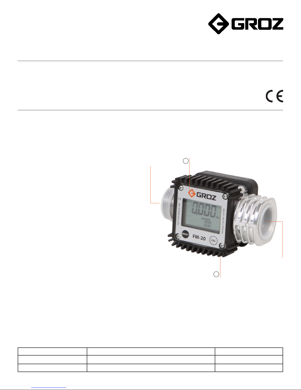
Congratulations on purchase of this World Class Digital Fuel Meter!
• Digital turbine meter designed to measure the flow of low
viscosity fluids
Meter
1
• Easy installation, both for in-line as well as end of line
applications; with advantage of Bi-directional operation
• Polyamide Turbine measuring mechanism
• Electronic Display powered by two AAA 1.5 V batteries
1” (M) Port
• Display can be rotated in four different positions
• Aluminum body and sealed electronic card makes it suitable
for use in severe weather conditions
• Features a non-volatile memory for storing the dispensing
data, in the event of a complete power break for long periods
• Measures in Litres, Quarts, Pints & Gallons
• Easy user recalibration
PART DESCRIPTION
Rubber Shroud
2
1” (F) Port
REFERENCE NUMBER DESCRIPTION QUANTITY
1
2
Meter
Rubber Shroud
1
1
1
Page 2

SPECIFICATIONS
Meter Type Digital
Meter Mechanism Turbine
Inlet / Outlet Position In-Line
Male / Female Port Size 1”
Threads BSP or NPT
Flow Rate 7 to 120 LPM ( 2 to 32 GPM )
Accuracy +/- 1%
Repeatability +/- 0.30 %
Max. Working Pressure 300 PSI ( 20 BAR)
Burst Pressure (Min.) 1500 PSI (100 BAR)
Pressure Loss at 100 LPM (27 GPM) with Diesel 4.5 PSI (0.30 BAR)
Working Temperature Range -10° C to +50° C (14° F to 122° F)
Max Resettable Batch Total 99999 Units
Max Non Resettable Totalizer 9,99,999 Units
Least Count/ Resolution 0.001 Unit
Filter/ Screen Included No
Viscosity of Media (Range) 2 – 5.35 cSt
Option to Recalibrate by User Yes
No. of positions in which the display can be rotated 4
Protective Shroud on Meter YES
Weights & Measures Approved NO
Calibration Certificate Included NO
Water resistance IP65
CE Listed YES
For use with Electric Fuel Pumps YES
For use with Gravity Flow YES (Minimum 4 feet head is required)
Power supply 2 x 1.5 Alkaline batteries ( Size AAA )
RECOMMENDED USE
Diesel, Gasoline, Bio-Diesel, Windshield Fluid, Water
DO NOT USE WITH
Oils
WETTED COMPONENTS
Aluminum, Polyamide
In order to improve the life of the turbine, it is recommended to fit
a filter before the meter itself.
2
Page 3
INSTALLATION
This is a bi-directional meter with 1” threaded male & female
ports. The meter can be installed in any position - fixed in line or
mobile on a control nozzle.
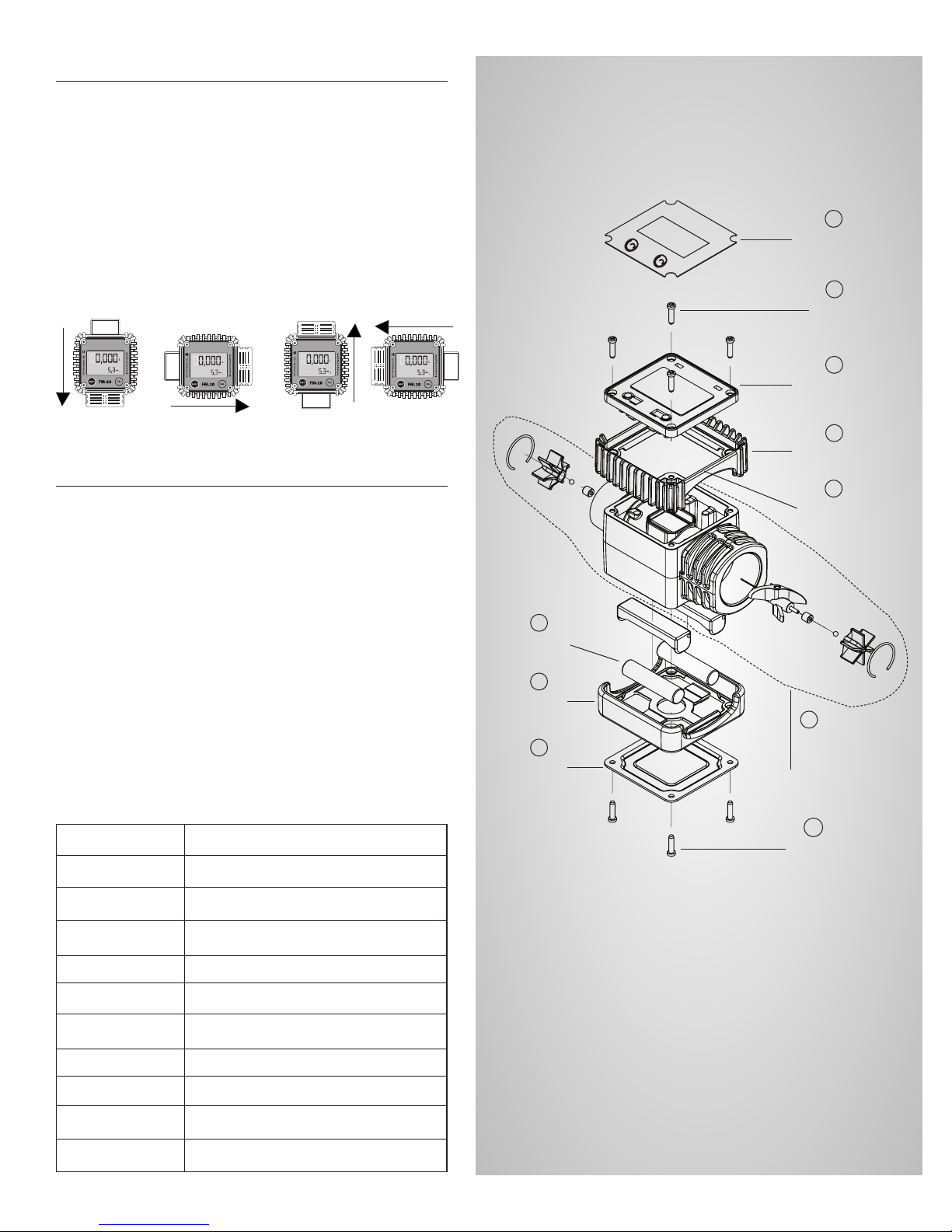
How to rotate the display
1. Remove the four screws (2) and separate the card housing
(5) from the turbine assembly (6).
2. Rotate the card housing in any of the four positions as shown
in the picture and tighten the card housing with four screws
(2)
KNOW ABOUT YOUR FLOW METER
Table of Contents
A. Component List & Exploded View
B. Major Components
C. Measurement Units Configuration
D. Normal Dispensing Mode
E. Resetting The Batch Total
F. Resetting The Reset Total
G. Dispensing with Flow Rate Mode display
H. Calibration
I. Calibration Procedures –
• In-Field Calibration Sequence,
• Direct Calibration Sequence
A. COMPONENT LIST & EXPLODED VIEW
7
Batteries
8
Battery
Case
9
Battery
Cap
1
Meter Label
2
Screws
4 Nos.
3
Display with
Microprocesser
4
Rubber Shroud
5
Card Housing
6
Turbine Assembly
(as a Single Unit)
Sl. No. Component List
1 Meter Label
2 Screw (Nos. 4)
3 Display with Microprocessor
4 Rubber Shroud
5 Card Housing
6 Turbine Assembly (as a Single Unit)
7 Batteries
8 Battery Case
9 Battery Cap
10 Screw (Nos. 4)
10
Screws
4 Nos.
3
Page 4
B. MAJOR COMPONENTS
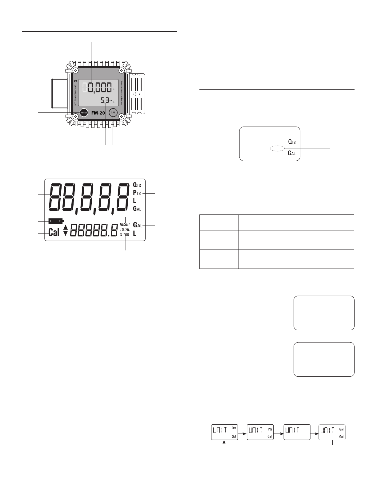
Resettable
Batch Total
Reset Key
Turbine Assembly It has two threaded ports: 1 male & 1 female. It contains a
turbine which turns when media passes through it with sufficient
1” Female Port1” Male Port
pressure. This action generates electrical pulses which are
processed by a microprocessor and the result is displayed on the
Totals of LCD.
WHAT IS STANDBY ?
When the media is not flowing through the meter, the meter
shows only the word TOTAL on the display. This mode is called
STANDBY and majority of adjusments are carried out in this mode.
Non Resettable
Totalizer
Calibration
Key
LCD DISPLAY - Powered by two alkaline batteries of 1.5 V each.
Includes three numerical Totals and other keys as given below:
1
2
3
FLOW RATE
4
5
8
6
7
1. Resettable Batch Total (5 figures with moving comma)-
indicates volume dispensed after RESET button was last
pressed.
2. Indication of battery charge.
3. Indication of calibration mode.
4. Batch Totalizer (6 figures with moving comma in multiple
of 10 & 100) - indicates two types of Total:
• Non-Resettable General Total (TOTAL)
• Resettable total (Reset TOTAL)
5. Indication of total multiplication factor (x10 or x100 ).
6. Indication of type of total, (TOTAL / Reset TOTAL).
7. Indication of unit of measurement of Totalizer:
L=Litres
Gal=Gallons
8. Indication of unit of measurement of Resettable Batch Total:
Qts=Quarts
Pts=Pints
L=Litres
Gal=Gallons
User Buttons - The meter features two buttons (RESET and
CAL) which individually perform two main functions and together,
other secondary functions.
• RESET key - is used to reset the Batch Total and Reset Total
• CAL key - is used to enter calibration mode
• Combination of RESET + CAL keys - is used to change the
unit of measurement
12,435
TOTAL
Standby
Mode
1345,6
C. MEASUREMENT UNITS CONFIGURATION
The user can select the main measurement unit, Quarts (Qts),
Pints (Pts), Litres (L), Gallons (Gal); according to the following
predefined combinations:
Reference No
Unit of Measurement
Batch Total
1 Litres (L) Litres (L)
2 Gallon (Gal) Gallon (Gal)
3 Quarts (Qts) Gallon (Gal)
4 Pints (Pts) Gallon (Gal)
SEQUENCE OF SETTING THE UNIT OF MEASUREMENT
1. Wait for the METER to go to
Standby Mode.
2. Press the CAL and RESET keys
together. Keep these pressed
until the word “UNIT” appears on
the screen together with the
current unit of measurement.
3. Press RESET key to scroll among the four combinations of
units of measurement as shown :
R RR
Unit of Measurement
Total Register
12,345
123456
Unit
TOTAL
QTS
GAL
QTS
GAL
L
L
4
Page 5
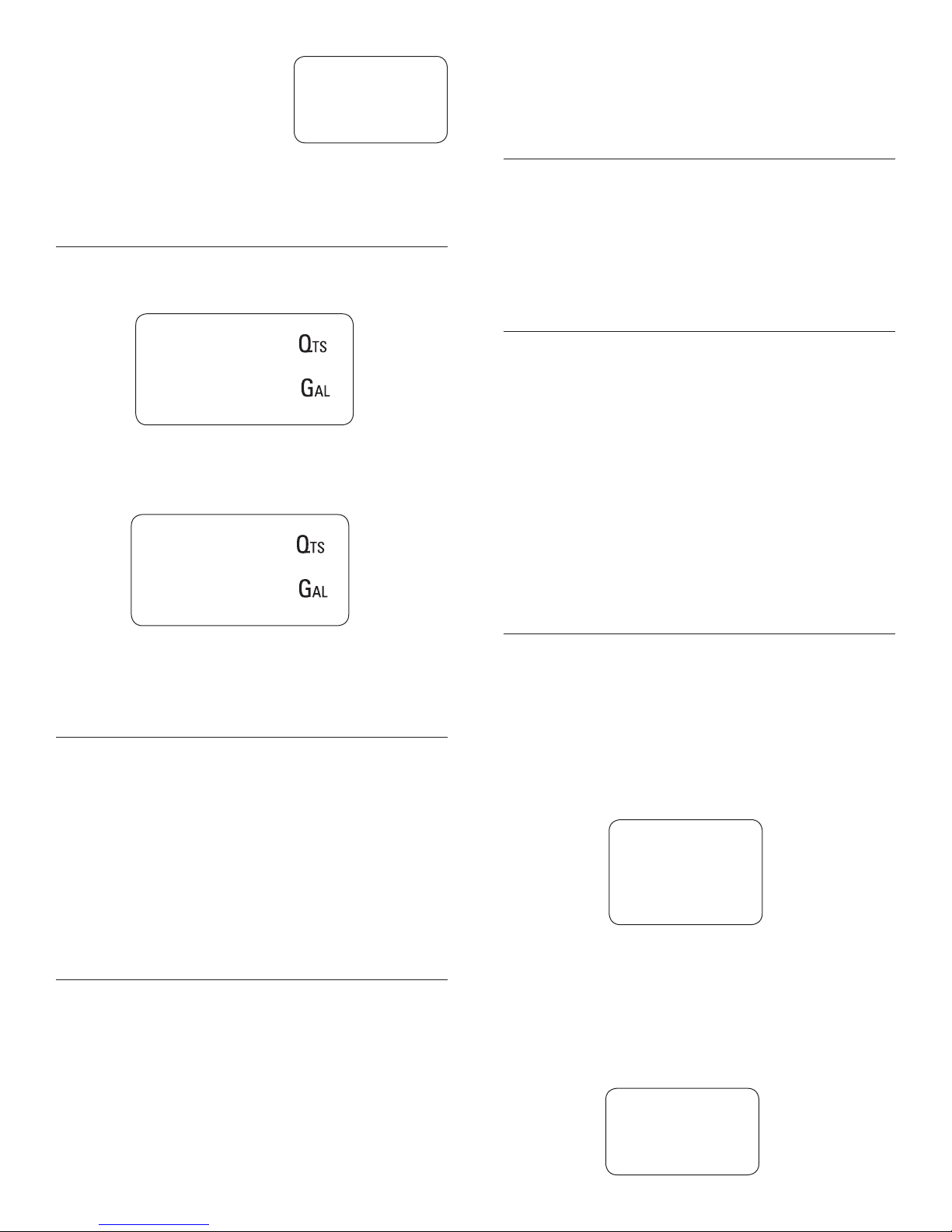
4. Press CAL key for more than
2 seconds to store the new
settings. The METER will pass
through the start cycle and
come back to the Stand by
Mode.No new calibration is
required after changing the
Unit of Measurement.
12,345
TOTAL
2342,3
D. NORMAL DISPENSING MODE
While the media is flowing through the meter, Batch Total and
Reset Total are displayed at the same time.
5. The display screen again shows all the segments of the
L
L
display followed by all the switched-off segments and finally
shows the display page where the new Reset Total is shown.
G. DISPENSING WITH FLOW RATE MODE DISPLAY
1. In standby mode, press the CAL key and start dispensing the
media.
2. The display will start showing “FLOW RATE”, in place of
TOTAL.
3. To return to standby mode, stop dispensing & when the flow
rate becomes zero, press CAL key once again.
H. CALIBRATION
12,345
Reset
12.3
A few seconds after dispensing has ended, on the lower Total,
the display switches from Reset Total to General Total: the word
RESET above the word TOTAL disappears, and the Reset Total is
replaced by the General Total.
TOTAL
12,345
12.3
This situation , where only “TOTAL” is displayed, is called
STANDBY mode. It remains stable until the user operates the
meter again.
E. RESETTING THE BATCH TOTAL
1. While in standby (i.e when the display shows TOTAL), press
the RESET button.
2. During reset, the display screen first of all shows all the lit-up
digits and then all the switched off digits.
3. At the end of the process, a display page is first of all shown
with the reset batch and the Reset TOTAL
4. After a few moments, the Reset TOTAL is replaced by TOTAL.
TOTAL
In standby mode, press the CAL key for more than 2 seconds to
see the current calibration factor.
• Factory K Factor: Factory-set default factor.
It is equal to 1 (indicated as 1,000).
• User K Factor: Customized calibration factor,
meaning modified by calibration.
The meter has been calibrated at the factory under the following
operating conditions:
Fluid : Diesel fuel
Temperature : 20°C (68° F)
Flow rate : 50 LPM (13 GPM)
Calibration is needed to make the meter suitable for actual
conditions.
I. CALIBRATION PROCEDURES
1. In-Field Calibration
2. Direct Calibration
By pressing the CAL key while the meter is in Standby, the display
shows the current calibration factor used. Two cases can occur:
CASE 1:
If no calibration has ever been performed, or the factory setting
has been restored after previous calibrations, the following display
page will appear:
1,000
Cal FACT
F. RESETTING THE RESET TOTAL
The Reset Total can be reset by pressing the RESET key at length
while the display screen shows Reset TOTAL. The steps to be
taken are:
1. Wait untill the display shows Total only (standby mode)
2. Press the RESET key quickly.
3. The meter starts to reset the Batch Total.
4. While the display page showing the Reset Total is displayed,
press the Reset key again for at least 1 second.
The word “Fact” abbreviation for “factory” shows that the
factory calibration factor is being used.
CASE 2:
If, on the other hand, calibrations have been made by the
user, the display page will appear showing the currently used
calibration factor ( in our example 0,998) .
0,998
Cal USER
5
Page 6
The word “user” indicates that a calibration factor, set by the
user is being used.
To confirm the choice of calibration factor, quickly press CAL
while “User” or “Fact” are displayed.
After the restart cycle, the meter uses the calibration factor that
has just been confirmed
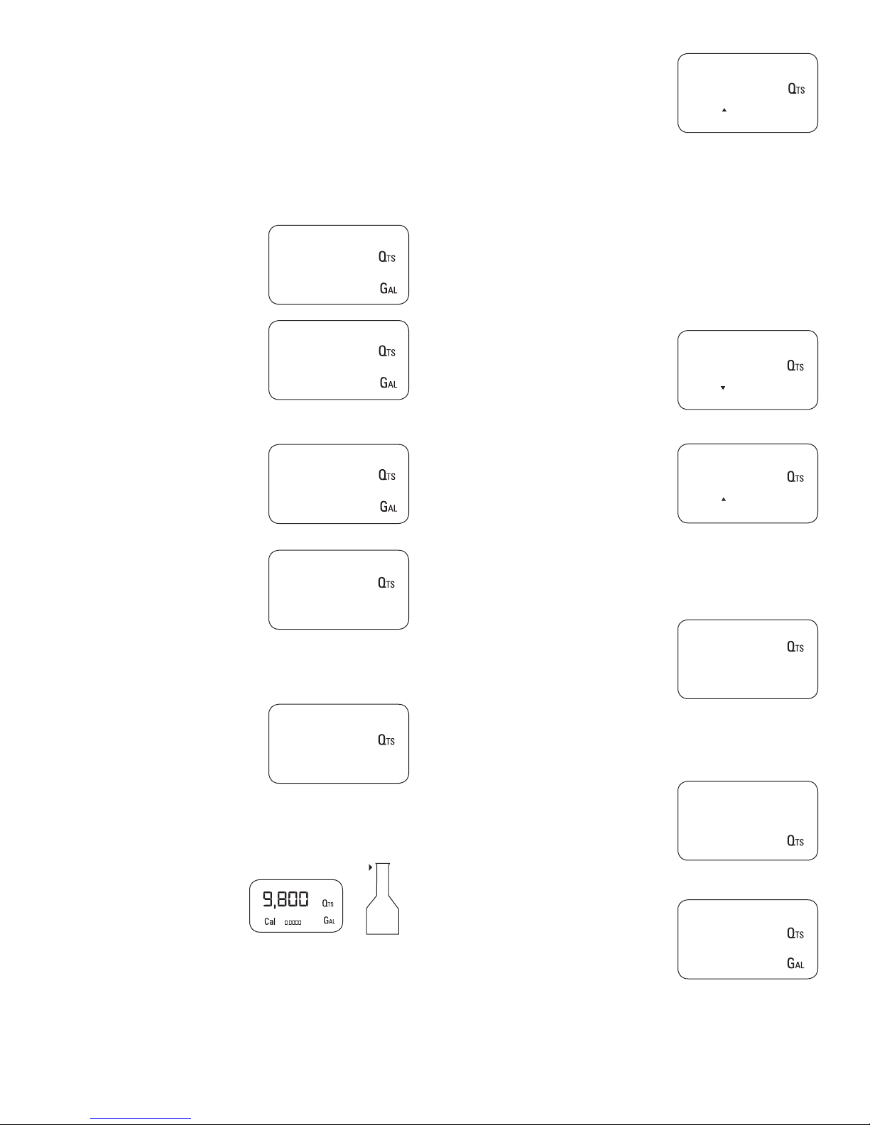
IN-FIELD CALIBRATION SEQUENCE
1. Wait until the METER comes in
Standby (Display shows TOTAL).
12,345
TOTAL
12,5
5. Press RESET key once.
The METER detects that
the calibration dispensing is
finished. An arrow (up/down)
appears which indicates the
direction in which the value can
be changed via steps 6 & 7. To
calibrate the METER, the value
indicated by the Batch total
(example 9.800) must be forced
to the Container value marked
on the graduated sample
container.
9,800
Cal FIELD
2. Press CAL key for more than 2
seconds. The METER enters
calibration mode and shows
“CAL”. The words “FACT” and
“USER” indicate which factor
(factory or user) is currently
in use.
3. Press RESET key for more than 2
seconds. The METER shows
“FIELD” and the Batch Total
at zero. The meter is ready
to perform in-field calibration.
4. DISPENSING INTO SAMPLE
CONTAINER
Without pressing any key,
start dispensing into the
sample container.
Dispensing can be interrupted
and started again at will.
Continue dispensing until
the level of the fluid in the
sample container has reached
the graduated area. There is
no need to reach a
preset quantity.
1,000
Cal
1,000
Cal
0,000
Cal FIELD
9,800
Cal FIELD
Meter Value
FACT
OR
USER
Container Value
9.86
6. Press RESET key once. The
arrow changes direction. The
operation can be repeated
to alternate the direction of the
arrow.
7. Press “CAL” key to change the
value in the direction indicated
by the arrow. The reading
changes
• by one unit for every short
press of CAL key.
• continually if the CAL
key is kept pressed.
8. Press RESET key for more than
2 seconds .
The METER is informed
that the calibration procedure
is finished.
The meter calculates the new
USER K FACTOR factor for a
few seconds.
9. The new USER K FACTOR is
shown for a few seconds,
after which the restart cycle
is repeated to finally achieve
standby condition.
10. The METER stores the new
calibration factor and is
ready to begin dispensing.
9,800
Cal FIELD
9,860
Cal FIELD
-----
Cal END
1,015
Cal END
0,000
12145
6
Page 7
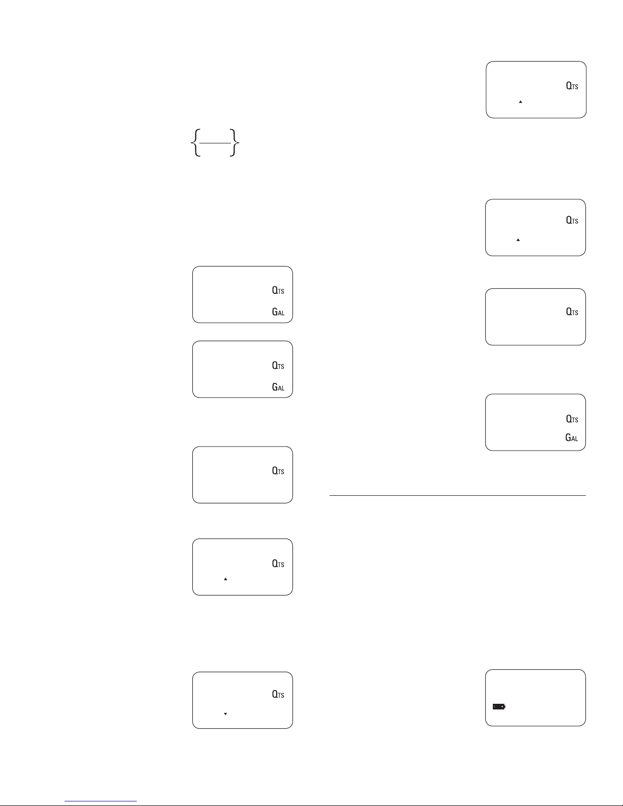
DIRECT CALIBRATION SEQUENCE
If normal METER operation shows a mean percentage error
E, (obtainable on the basis of several performed dispensing
operations ), this can be corrected by applying a correction to the
current calibration factor as shown below :-
New cal. Factor = Old Cal Factor X 100 - E
100
Example:
Error percentage found E% = - 0.3 %
CURRENT calibration factor = 1.000
New USER K FACTOR = 1.000 * [(100 – ( - 0.3))/100]
= 1.000 * [(100 + 0.3)/100]
= 1.003
1. Wait until the METER comes in
Standby (Display shows TOTAL).
2. Press CAL key for more than 2
seconds.
The METER enters calibration
mode and shows “CAL”. The
words “Fact” and “USER”
indicate which factor (factory
or user) is currently in use.
3. Press RESET key for more than
2 seconds.
The METER shows “CAL” and
the Batch Total at zero. The
meter is ready to perform in field calibration.
4. Press RESET key for more than
2 seconds.
“Direct” appears together with
the Current calibration factor.
In the bottom left part of the
display, an arrow appears
(upwards or downwards)
defining the direction (increase
or decrease) of the reading.
12,345
12.5
TOTAL
1,000
FACT
Cal
USER
0,000
Cal FIELD
1,000
Cal DIRECT
6. By pressing CAL key, the Meter
value changes in the direction
indicated by the arrow,
• one unit for every short
press of CAL key .
• continually if the CAL key
is kept pressed. The speed
increase rises by keeping
the key pressed.
7. Press RESET key for more
than 2 seconds.
The METER detects that
the desired reading has been
set and the calibration procedure
is finished.
8. At the end of the calculation, the
new USER K FACTOR is shown
for a few seconds.
9. The restart cycle is repeated to
finally achieve standby mode.
1,003
Cal DIRECT
-----
Cal DIRECT
1,003
Cal END
12,345
TOTAL
12.5
MAINTENANCE
The Meter has been designed to require a minimum amount of
maintenance.
The only maintenance jobs required are:
• Battery change - Necessary when the batteries have run
down
• Cleaning the turbine assembly - Due to the presence of
solid particles following bad filtering.
CHANGING THE BATTERY
The METER features two low-battery alarm levels
5. By pressing RESET key
the user can change the
direction of the arrow.
1,000
Cal DIRECT
1. When the battery charge falls
below the first level on the
LCD, the fixed battery symbol
appears. In this condition, the
METER continues to operate
correctly, but the fixed icon
warns the user that it is time
to change the batteries.
7
12,345
2342,3
QTS
TOTAL
GAL
Page 8

2. If meter operation continues
without changing the batteries,
the second battery alarm
level will be reached which
will prevent operation. In this
condition the battery icon starts
to flash and is the only one to
remain visible on the LCD.
BATTERY REPLACEMENT PROCEDURE :
• Press RESET to update all the totals
• Remove the four screws (10) and separate the battery cap (9).
• Remove the old batteries.
• Place the new batteries in the same position as the old ones,
making sure the positive pole is positioned as indicated.
• Re-tighten the battery cap (9).
• The METER will switch on automatically and normal operation
can be resumed. The old calibration will stay same as before.
TROUBLESHOOTING
CLEANING OF THE TURBINE ASSEMBLY
After removing the meter from pipes, any residual elements can
be removed from the turbine by simply washing it with water.
Always make sure the liquid has been drained from the meter
and the line presure is released before cleaning.
Never use compressed air for cleaning as it may damage the
turbine assembly.
Problem Possible Cause Corrective Action
No indication on display Bad battery contact Check battery contacts
Wrong Calibration Follow CALIBRATION procedure
Inaccurate measurement
The meter works below minimum acceptable
flow rate.
Increase the flow rate until an acceptable
flow rate range has been achieved
Reduced or zero flow rate TURBINE blocked Clean the TURBINE
The meter does not count, but the flow rate
is correct
Groz Engineering Tools (P) Ltd.
Groz Net Industries
Village Kherki Daula, National Highway-8
Gurgaon-122001, Haryana, INDIA
TEL +91.124.282.7700 / 221.4050
FAX +91.124.2827986 / 221.4224
FAX (USA) +1.509.271.7848
FAX (UK) +44.870.121.1854
Incorrect installation of the card Reinstall the card
Possible electronic card problems Contact your dealer
E-MAIL [email protected]
URL www.groz-tools.com
The Groz name, Groz logo and the mark are
trademarks of Groz Engineering Tools (P) Ltd. India
8
 Loading...