

GrowSpan Estate Elite Attached Greenhouses Instructions Manual
GROWSPAN™ ESTATE ELITE ATTACHED GREENHOUSES
GrowSpan™
Estate Elite Attached Greenhouses
©2016 Growers Supply
All Rights Reserved. Reproduction
is prohibited without permission.
Revision date: 01.01.16
Photo may show a different but similar model.
STK# DIMENSIONS
104711 6'-4" W x 8'-3" H x 8'-6" L
104713 6'-4" W x 8'-3" H x 12'-6" L
104715 6'-4" W x 8'-3" H x 16'-6" L
1
GROWSPAN™ ESTATE ELITE ATTACHED GREENHOUSES
YOU MUST READ THIS DOCUMENT BEFORE YOU
BEGIN TO ASSEMBLE THE SHELTER.
LOCATION
Choosing the proper location is an important step before
you begin to assemble the structure.
The following suggestions and precautions will help you
determine whether your selected location is the best
location.
• Never erect the structure under power lines.
Thank you for purchasing this GrowSpan™ greenhouse.
When properly assembled and maintained, this product will
provide years of reliable service. These instructions include
helpful hints and important information needed to safely
assemble and properly maintain the greenhouse. Please
read these instructions before you begin.
If you have any questions during the assembly, contact
Customer Service at 1-800-245-9881 for assistance.
SAFETY PRECAUTIONS
• Wear eye protection.
• Wear gloves when handling panels and frame parts.
• Use a portable GFCI when working with power tools
and cords.
• Do not climb on the greenhouse or framing during or
after construction.
• Do not occupy the greenhouse during high winds,
tornadoes, or hurricanes.
• Provide adequate ventilation if the structure is
enclosed.
• Do not store hazardous materials in the greenhouse
without proper ventilation.
• Provide proper ingress and egress to prevent
entrapment.
• Identify whether underground cables and pipes are
present before preparing the site or anchoring the
structure.
• Location should be away from structures that could
cause snow to drift on or around the building.
• Do not position the greenhouse where large loads
such as snow and ice, large tree branches, or other
overhead obstacles could fall.
• Always check local building codes before you begin.
SITE
After choosing a location, proper preparation of the site is
essential. The following site characteristics will help ensure
the integrity of the structure.
• A level site is required. The site must be level to
properly and safely erect and anchor the structure.
• Drainage: Water draining off the structure and from
areas surrounding the site should drain away from the
site to prevent damage to the site, the structure, and
contents of the structure.
WARNING: The individuals assembling this structure
are responsible for designing and furnishing all
temporary bracing, shoring and support needed during
the assembly process. For safety reasons, those who
are not familiar with recognized construction methods
must seek the help of a qualified contractor.
ANCHORING INSTRUCTIONS
Prior to assembling this greenhouse, please read the
MUST READ document included with the shipment.
WARNING: The anchor assembly is an integral part
of the greenhouse construction. Improper anchoring
may cause greenhouse instability and failure of the
structure. Failing to anchor the greenhouse properly
will void the manufacturer’s warranty and may cause
serious injury and damage.
See additional anchoring information beginning on
page 24.
2
ASSEMBLY NOTE
The assembly of this greenhouse is not complex; however,
it does take time and additional assistance. For best results
and an overview of the entire assembly, read through
these instructions before you begin. Then, follow these
instructions as presented.
Examine all diagrams and photos and verify that you have
selected the proper parts from the correct box or boxes. Do
not mix parts from different boxes. When checking parts,
place the parts back into the same box they were removed
from and continue with the next box.
Cover the assembly surface with cardboard or similar
material to protect the greenhouse finish during
assembly.
Revision date: 01.01.16
ASSEMBLY PROCEDURE
GROWSPAN™ ESTATE ELITE ATTACHED GREENHOUSES
GREENHOUSE PARTS
Following the instructions as presented will help ensure
the proper assembly of your greenhouse. Failing to follow
these steps may result in an improperly assembled and
anchored greenhouse and will void all warranty and
protection the owner is entitled.
The steps outlining the assembly process are as follows:
1. Verify that all parts are included in the shipment. Notify
Customer Service for questions or concerns.
2. Read these instructions and all additional
documentation included with the shipment before you
begin assembling the greenhouse.
Use these instructions and the bill of materials list
inside each box when assembling the greenhouse.
3. Gather the tools, bracing, ladders (and lifts if
applicable), and assistance needed to assemble the
greenhouse.
4. Re-evaluate the location and site based on the
information and precautions presented in the
documentation included with the shipment.
5. Lay out the site (if this has not been completed).
All greenhouse sections (e.g., roof, sides, end walls, etc.)
ship individually in numbered boxes. The quantity of boxes
may differ depending on the greenhouse.
To prevent mixing the parts while assembling the
greenhouse, select the boxes as instructed and open that
box only and assemble its contents.
OPEN BOXES AS INSTRUCTED TO PREVENT MIXING
OF THE CONTENTS.
NOTE: Some photos and diagrams throughout these
instructions may show a greenhouse with slightly different
dimensions, color, or design. The assembly procedures
are identical regardless of these differences. Notable
differences are addressed.
For a quick overview of this greenhouse, consult the
diagrams in the Quick Start section near the back of these
instructions.
Those not familiar with the assembly of similar structures
and the use of common hand tools must seek the
assistance of someone with such experience.
6. Assemble the base frame and greenhouse components
in the order they are presented in these instructions.
7. Anchor the greenhouse as instructed. See information
beginning on page 24.
8. Read the Greenhouse Care and Maintenance
information near the end of these instructions.
9. Complete and return all warranty information as
instructed.
REQUIRED TOOLS
The following list identifies the main tools needed to
assemble the shelter. Additional tools and supports may be
needed depending on the structure, location, and
application.
• Tape measure or measuring device
• Marker to mark UV-side of panels during assembly
• Variable speed drill and sockets (cordless with
extra batteries works best)
• Small hammer and gloves
• Adjustable pliers and wrench (or ratchet)
WARNING: Do not allow the polycarbonate panels to
remain in direct sunlight until they are installed. Doing
so will cause the protective film to become difficult if not
impossible to remove.
Consult Page 32 for additional polycarbonate
information. And, Step 10 on that page, for "how to use
vent tape" (additional purchase required) information
before installing any polycarbonate panel.
PART IDENTIFICATION NUMBERS
All main parts include a stamped ID number. Use this
number when selecting the required parts during the
assembly.
17
17
• Phillips screwdriver
• Ladders and/or work platforms
• Caulk gun for silicone application
Revision date: 01.01.16
NOTE: The locations of the part numbers on the
components may vary. Refer to the Bill of Materials shipped
within each box for a description of each part.
3
GROWSPAN™ ESTATE ELITE ATTACHED GREENHOUSES
Estate Elite Attached Greenhouses
OVERVIEW
GrowSpan™
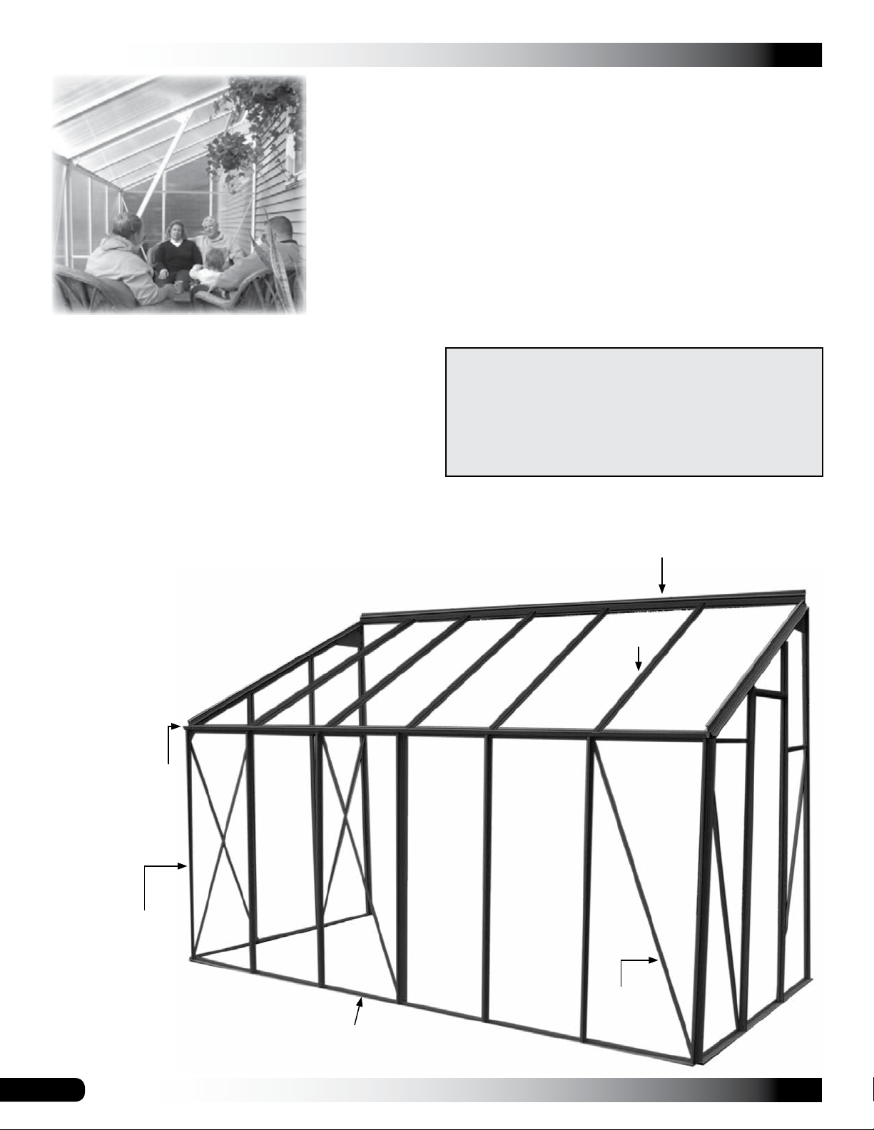
This section describes assembling your Elite greenhouse.
See illustration below to identify main parts of greenhouse.
1. Locate the required parts for each assembly procedure.
2. Preassemble the base frame, end walls and sidewalls.
3. Assemble the frame and install the ridge beam, rafters
and vents.
4. Square and anchor the greenhouse.
5. Assemble and install door.
6. Attach gutter rails ends.
7. Install the side, end and
roof polycarbonate panels.
8. Assemble and attach door,
door stops, down spouts, and
ridge beam end covers.
ATTENTION: TO AVOID TWISTING OFF OR DAMAGING
THE FASTENERS, DO NOT OVERTIGHTEN.
FOR YOUR CONVENIENCE, ADDITIONAL FASTENERS
CAN BE FOUND IN THE "EXTRA PARTS" BAG OR BOX.
REFER TO THE BILL OF MATERIALS FOR A LIST OF
THE FASTENERS CONTAINED IN THAT BAG OR BOX.
Ridge Beam
Rafters
Gutter Rail
Vertical Support:
Sidewall
Actual strut position may
differ from what is shown
in this example.
4
Diagonal
Strut
Base Rail
Revision date: 01.01.16
BASE FRAME ASSEMBLY (ADDITIONAL PURCHASE)
The optional base frame provides a level, square surface
on which to set the greenhouse frame. It is strongly
recommended that you use this base.
The optional base is assembled and squared and set into
the ground. It is then anchored in place using ground posts
or other approved anchoring methods described in these
instructions.
This base is an additional purchase. Contact your sales
consultant for additional information and to purchase.
NOTE: The frame in the following instructions may differ
from the actual frame in size and/or color. The assembly
procedures are the same.
CONSULT THE BASE DIAGRAM NEAR THE BACK OF
THIS PACKET BEFORE YOU BEGIN.
The following steps describe how to assemble the optional
base frame for the greenhouse.
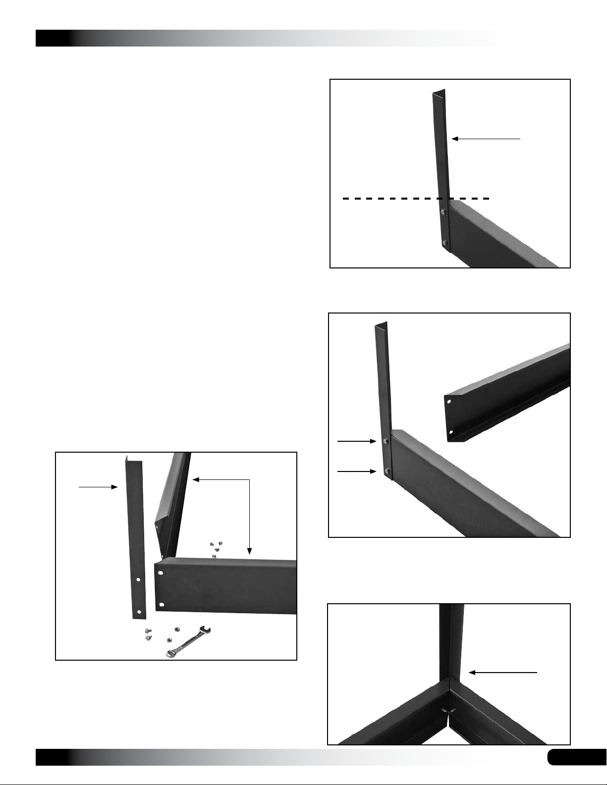
GROWSPAN™ ESTATE ELITE ATTACHED GREENHOUSES
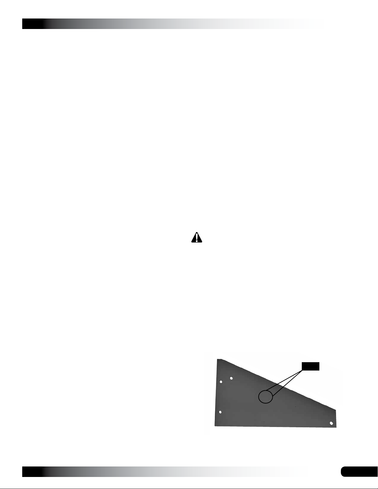
Cut these only if you plan to place the frame, and
ultimately the greenhouse, on a concrete slab.
Leg portion of
IMPORTANT:
Dashed line shows
where to cut when
removing the
leg for use on
concrete only.
4. Insert two bolts through the pre-drilled holes in the post
and one base channel and add the nuts.
frame support post
1. Unpack the base kit to identify the parts.
NOTE: The base is assembled upside down and then
is flipped when it is positioned on the site.
2. Identify the base channel lengths used for the ends
(width) and the sides (length).
3. Select the first frame support post and the required
nuts and bolts and place these at one corner of the
base.
Support
Post
Base
Channels
NOTE: Do not tighten the bolts at this time.
5. Select the remaining bolts and repeat the previous step
to attach the remaining base channel to the support
post.
ATTENTION: If you plan to place the base on a
concrete slab or patio, you must remove the "leg"
portion of the frame support posts. Before you
assemble the base as shown below, cut the frame
support posts so they are the same length as the base
channel is wide.
Revision date: 01.01.16
Support Post
5

GROWSPAN™ ESTATE ELITE ATTACHED GREENHOUSES
BASE FRAME ASSEMBLY (CONTINUED)
SQUARE THE BASE
6. Verify that the post is straight and tighten the bolts.
7. Repeat the procedure to attach the remaining support
posts to the base channels.
Dotted line shows an optional location for the support
post depending on the site.
8. After the frame is assembled and all bolts are tight, flip
the base over and set it on the site.
Top of
base
Before the support posts of the base are driven into the
ground and before the assembled greenhouse frame is
set on and secured to the base, you must square the base
assembly and anchor the base to the site.
This base and greenhouse require a level site. Before
setting the base or greenhouse frame (or both) in place,
you must level the site.
The easiest way to square the base is to measure
diagonally from corner to corner.
Complete these steps:
NOTE: The following procedure describes how to square
the base on a prepared site and drive the base support
posts into the ground.
1. Position the assembled base on the site as shown in
the diagram below.
2. Measure diagonally from corner-to-corner.
Insert shows how the support post is attached to the
base channel.
9. Continue with the next procedure.
IMPORTANT: Customer must determine how to attach
the assembled greenhouse to the permanent structure.
Fasteners for this procedure are not included due to the
variety of exterior finishes.
All silicone, fasteners, and weather stripping included
with this greenhouse are used during the construction of
the greenhouse.
Consult the services of a qualified contractor for
suggestions to secure and seal the greenhouse to the
permanent structure.
Greenhouse
Base Frame
Permanent
Structure
NOTE: The frame is square when both measurements
are the same. Dashed line shows the structure that the
greenhouse is attached to.
3. When the frame is square, tap the support posts into
the ground to set the frame in place and recheck the
measurements.
NOTE: Place a block of wood on top of the base
channel and support post and hammer on the wood to
protect the frame when driving the posts into place.
4. Continue to drive the posts to the desired depth.
NOTE: Use a level (or string a line) to verify that the
base remains level when set into the ground. Secure
base frame ends to the permanent structure if desired.
5. After setting the base on the site, continue with the
greenhouse assembly.
6
Revision date: 01.01.16
GROWSPAN™ ESTATE ELITE ATTACHED GREENHOUSES
ASSEMBLE THE GABLE END WALL FRAMES
The greenhouse has two end walls: one with a door and
one without a door. The end walls are packaged separately.
Each package includes all the parts required for that end
wall. For the best results and to prevent mixing parts,
assemble each end wall separately as described below.
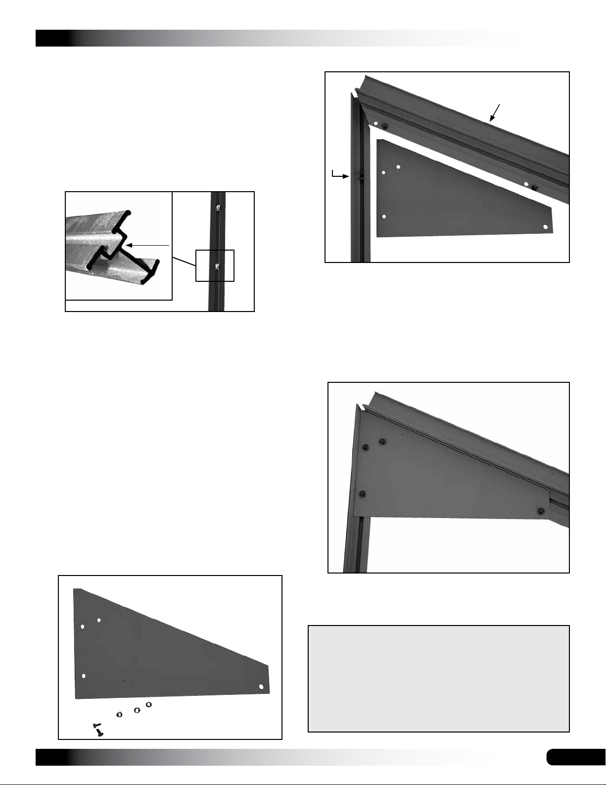
NOTE: All bolt tracks in the frame members are installed to
the inside of the greenhouse. All diagrams and individual
photos shown in these end wall instructions show the inside
surface of the frame unless otherwise noted.
Bolt Track
Photo shows vertical frame member for end walls. The bolt
track is installed to the inside of the greenhouse.
IMPORTANT: To prevent loosing parts, assemble all
frame components on a flat surface. A concrete driveway
or a garage floor works best. Cover surface to protect
greenhouse finish. As you assemble the frame sections,
the inside of the frame will face up as shown in the photos
that follow.
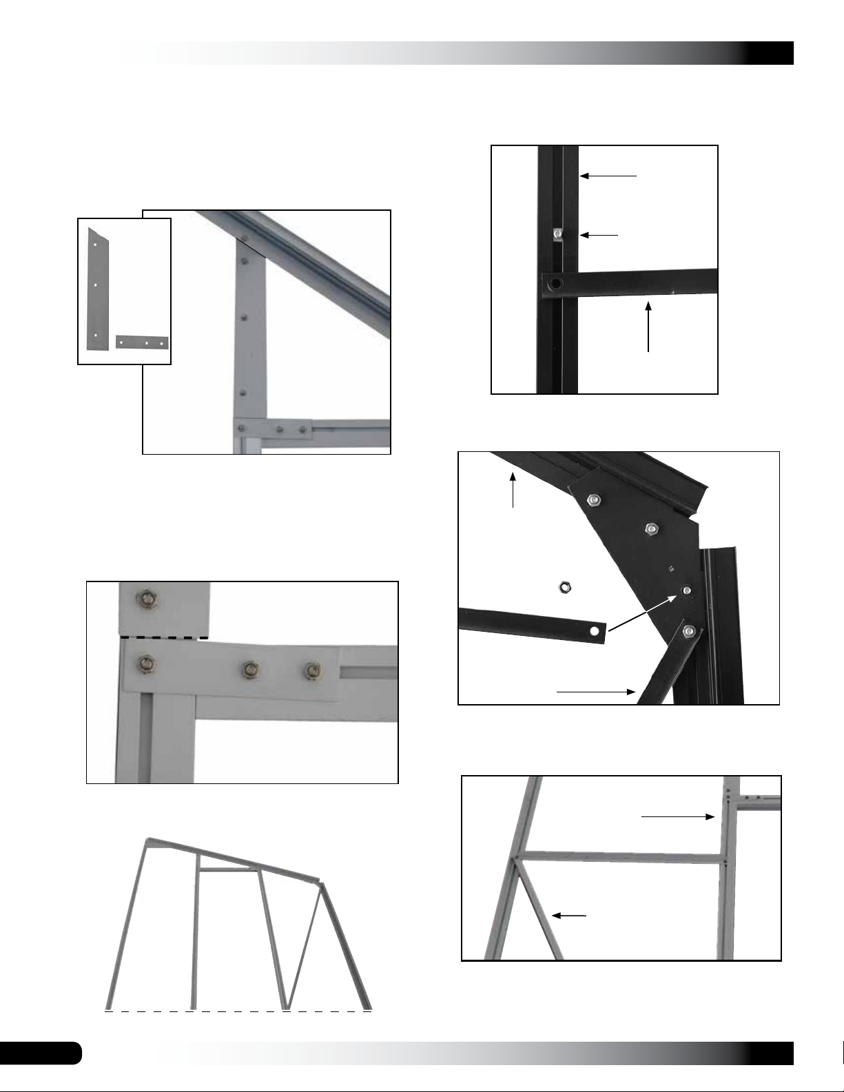
3. Locate the two supports for the end wall.
15
14A
17
The upper support includes pre-drilled holes and a
beveled edge. The long, lower support is attached to
the upper support by the top bracket. The long, lower
support is the support at the back of the greenhouse
and is used to attach the greenhouse to another
structure.
4. With the upper supports positioned as shown below,
secure the 17 bracket to the supports.
Complete the following steps to assemble the first end wall
frame. Consult the End Frame Diagrams near the back of
these instructions before you begin.
1. Open the package that includes the parts to assemble
the gable end frame that includes the door frame parts.
Consult the End Frame Diagram – Door End in the
Quick Start section (back) for part identification. Parts
may be packed in different poly bags.
2. Locate the top bracket used to join the upper supports
to long, lower support at the peak of the end wall.
17
14A
17
15
View shows the supports as seen from the inside of the
greenhouse.
ATTENTION: TO AVOID TWISTING OFF OR DAMAGING
THE FASTENERS, DO NOT OVERTIGHTEN.
Use the fasteners in the extra parts bag or box to replace
lost or damaged fasteners.
Search the items in the extra parts bag or box before you
call Customer Service to request replacement parts.
Revision date: 01.01.16
7
GROWSPAN™ ESTATE ELITE ATTACHED GREENHOUSES
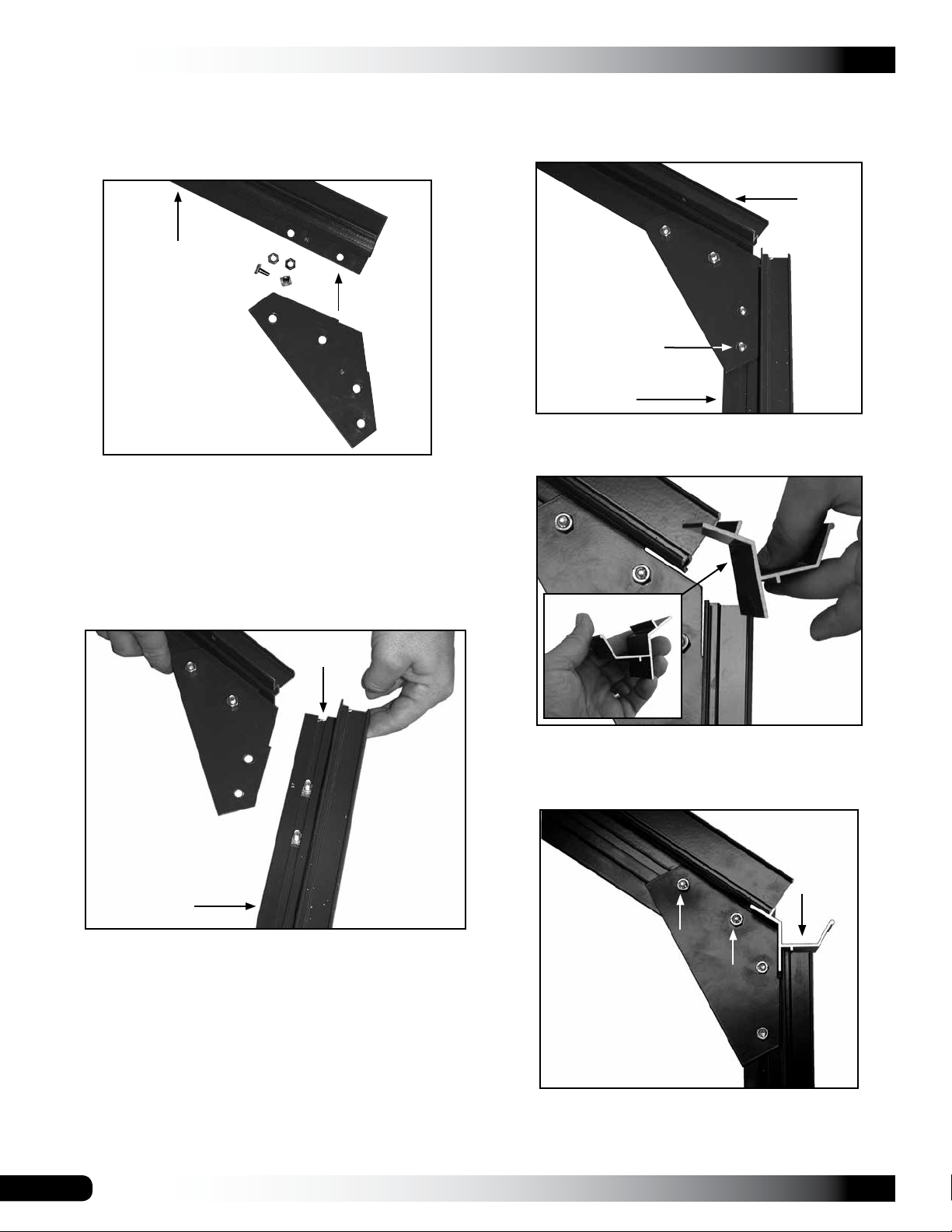
ASSEMBLE THE END WALL FRAMES (CONTINUED)
5. Locate the remaining angled bracket and attach it to
the end of the upper support. Do not tighten bolts at
this time.
Upper Support (15)
18
ATTENTION: Some upper supports may include a
bolt track instead of the pre-drilled holes as shown in
the photo. If so, slide bolts into the track and attach
bracket.
7. Attach the lower support to the angled bracket using
nuts and the bolts in the track. Insert bolts through
drilled holes of the bracket. Do not tighten bolts at this
time.
Upper Support (15)
18
Attach Strut Here
Lower Support (14)
8. Verify that the four bolts are loose and place the
template into position as shown in the photos below.
6. Select the short, lower support, slide two bolts into the
bolt track, and attach the lower support to the angled
bracket as shown below.
Slide bolt head
through here.
18
Lower Support (14)
REMINDER: Brackets are installed on the inside of the
shelter.
18
template
ATTENTION: The template is used to set the proper
clearance for the gutter rail. The template slides into
the slots in each frame member.
15
Template
18
14
9. With the template in position, tighten the upper bolts to
secure the bracket to the upper frame member (15) of
the end wall. See the arrows above.
8
Revision date: 01.01.16
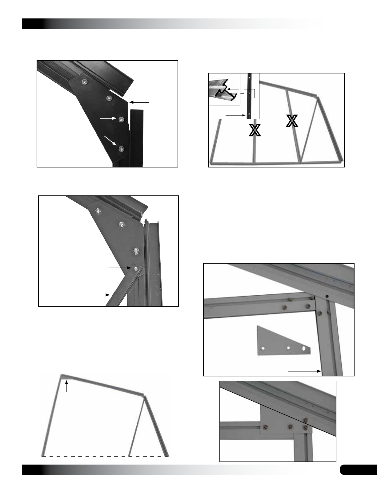
ASSEMBLE THE END WALL FRAMES (CONTINUED)
10. Slightly tighten the lower two bolts and remove the
template.
15
GROWSPAN™ ESTATE ELITE ATTACHED GREENHOUSES
12. Locate the two vertical supports (marked with an X's
below) that run between the upper support and the
base rail and slide seven (7) bolts into the track of the
12-2 support and four (4) bolts into the track of the
shorter 12-1 support.
Clearance
set using the
template.
18
14
11. Locate the first diagonal strut, loosen the lower bolt
identified by the arrow in the photo below and attach
one end of the diagonal strut to the bolt.
Bolt
Track
Vertical Support
12-1
X
X
12-2
These bolts are used to attach the vertical supports
to the upper support and the base rail. The remaining
bolts are used to secure brackets and the horizontal
braces of the end frame. See the End Frame Diagram
for clarification.
13. Take the header (65), bracket (65-2), and support
(12-1). Insert the top bolt of the support through the
pre-drilled hole in the upper support (15). Insert four (4)
bolts into track of header (65-1). Bracket fits over two
(2) bolts in the header and one bolt the 12-1 support.
Secure as shown below.
Lower Bolt
Diagonal Strut (13)
Consult the End Frame Diagram for clarification.
NOTE: Do not tighten the two bolts that secure the
lower support to the angled bracket at this time. The
diagonal strut must be allowed to move to align it with
the base rail of the end wall frame in a later step.
Gable end frame should resemble the photo below.
17
14
13
Inside View
15
Header (65)
65-2
Short, Vertical Support (12-1)
Base Rail Location
Revision date: 01.01.16
9
GROWSPAN™ ESTATE ELITE ATTACHED GREENHOUSES
ASSEMBLE THE END WALL FRAMES (CONTINUED)
14. Take the longer (12-2) support and the two brackets
(110 & 65-1). Insert the top bolt of the 12-2 support
through the pre-drilled hole in the upper support. Insert
the next 3 bolts into the pre-drilled holes of the 110
bracket. Position the angle of the bracket along the
lower edge of 12-2 support. See photo below.
Brackets
110
16. Locate a remaining bolt in the bolt track of the short
12-1 support and attach one horizontal brace (19) to
the bolt. Do not tighten the bolt at this time.
12-1
Bolt
19
65-1
15. Select the next bolt in the 12-2 support and insert the
bolt into the pre-drilled hole of the 65-1 rectangular
bracket. Insert the remaining two (2) bolts in the header
(65) track into the remaining holes of the 65-1 bracket.
Align Bracket 65-1 with the edge of the 110 bracket.
110
65-1
65
12-2
Horizontal Brace
17. Move to the angled bracket (18) and attach the brace
using the bolt as shown.
Upper Support
(15)
19
Diagonal Strut
18. Repeat steps to attach the remaining horizontal
brace (19) to the 12-2 support and the 14A end frame
support.
To this point the end frame should resemble the photo
below.
Base Rail Location
10
12-2
14A
19
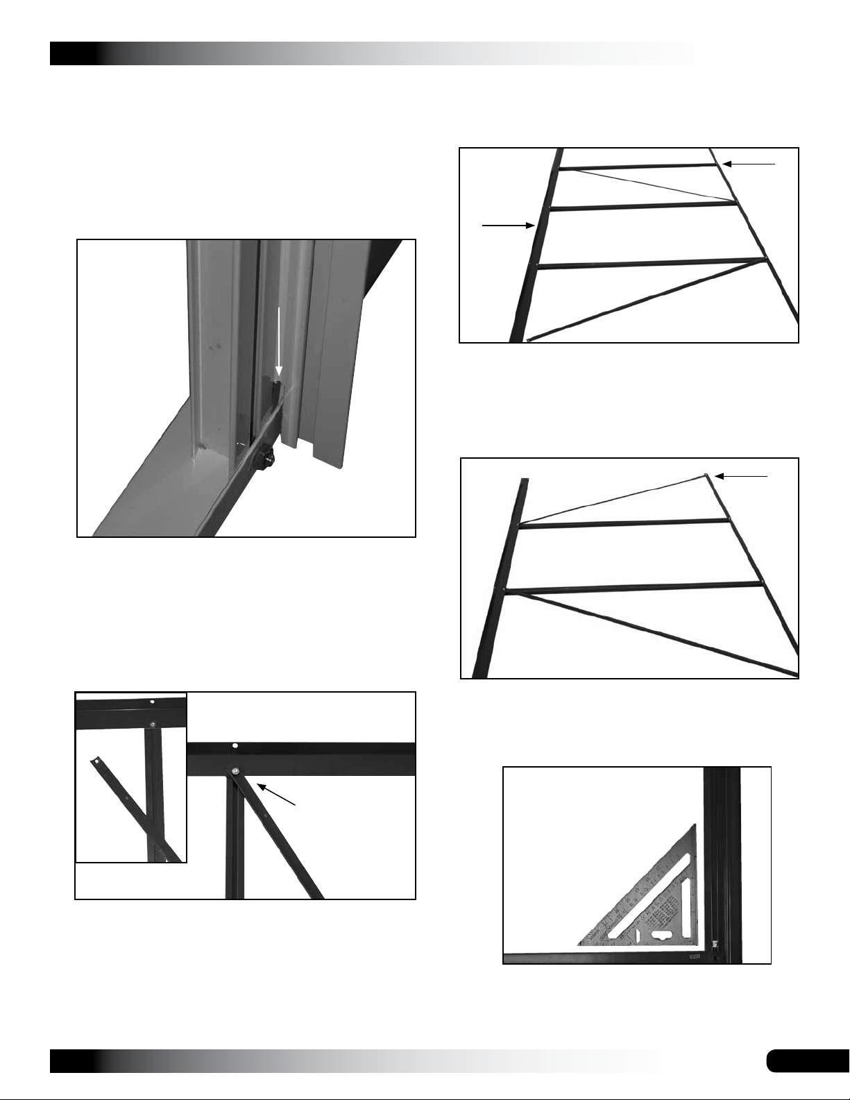
19. Attach the remaining diagonal strut (19).
Revision date: 01.01.16

GROWSPAN™ ESTATE ELITE ATTACHED GREENHOUSES
ASSEMBLE THE END WALL FRAMES (CONTINUED)
Up to this point, all end wall frame members are
attached except for the base rail. The dotted line shows
the position of the base rail. See photo below.
14A
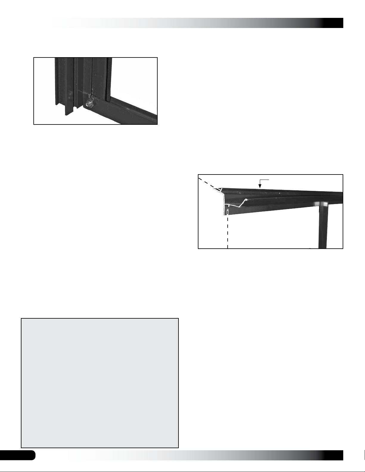
20. With the end wall assembled as shown, locate the base
rail (10) and position it at the ends of the lower supports
and vertical supports.
22. Take the free end of the diagonal strut and insert the
bolt of the door support through the pre-drilled hole in
the diagonal strut and install the nut.
ATTENTION: Verify that the bottom of the door support
is tightly seated against the top of the base rail before
you tighten the bolt and nut.
Vertical Support
14A
Notch toward the inside
of the greenhouse.
Base Rail (10)
NOTE: The slot used to attach the base rail to
the lower support is positioned to the inside of the
greenhouse. The view above is an end view of the
base rail. Actual rail may differ slightly in design.
21. With the base rail in position, insert the bolt of one (1)
door support through the pre-drilled hole in the base
rail and hold the bolt in place. Do not install the nut on
the bolt at this time.
Vertical Support
Flush to the top
of the base rail.
View is from the outside of the greenhouse looking
at the top of the base rail where the door support is
attached.
23. With the support tight against the top of the base rail,
tighten the nut and repeat the steps to attach the
remaining door support and diagonal strut to the end
wall base rail.
24. After attaching both struts and door supports to the
base rail, move to one end of the base rail and attach
the lower end of the vertical support.
Vertical Support
14A
Base Rail (10)
Revision date: 01.01.16
To the top of the
end wall frame.
Base Rail (10)
11
GROWSPAN™ ESTATE ELITE ATTACHED GREENHOUSES
ASSEMBLE THE END WALL FRAMES (CONTINUED)
25. Verify that the vertical support is seated flush with the
top of the base rail and tighten the bolt.
14A
26. Repeat the steps to attach the base rail to the
remaining lower support.
NOTE: Verify that the horizontal braces are parallel to
the base rail. Use a carpenter's square to verify that the
assembled frame is square before tightening all bolts.
If it appears that the assembled end frame is in a bind
or is twisted, loosen a few of the bolts in the angled
brackets or vertical supports and allow the frame to
settle and shape itself. Retighten the bolts as needed.
27. Repeat the procedure to assemble the remaining gable
end wall.
ATTENTION: The remaining end wall frame does not
include the header. In addition, the small horizontal
braces (19) of the first end wall have been replaced
by a single, longer horizontal brace (29). Keep these
changes in mind as you complete the assembly of the
remaining end wall frame.
Consult the End Frame Diagram: No Door when
assembling the frame if needed.
28. After assembling the last end wall frame, continue with
the Sidewall Assembly procedure that follows.
EXTRA PARTS PROVIDED FOR GREENHOUSE
ATTENTION: TO AVOID TWISTING OFF OR DAMAGING
THE FASTENERS, DO NOT OVERTIGHTEN.
FOR YOUR CONVENIENCE, ADDITIONAL FASTENERS
AND PLASTIC MOLDING CAN BE FOUND IN THE
"EXTRA PARTS" BAG OR BOX.
REFER TO THE BILL OF MATERIALS FOR A LIST OF
THE FASTENERS AND MOLDING CONTAINED IN THAT
BAG OR BOX.
The plastic profile can be trimmed to the required length if
a piece is misplaced or damaged during installation.
10
SIDEWALL ASSEMBLY
After both gable end wall frames are assembled, locate the
box labeled with the roof and sidewall parts. Remove the
plastic and assemble its contents as described below.
ATTENTION: Consult the Sidewall Frame Diagram for a
description of parts. All vertical supports are installed with
the bolt track to the inside of the greenhouse. Photos may
show a frame of a different color or length.
Greenhouse 104715: Consult the EXPLODED FRAME
COMPONENTS diagram near the back of these
instructions for important information regarding the
assembly of the gutter rail and base rail.
Complete these steps:
1. Unpack the sidewall parts and position them on a flat
surface for assembly. Place gutter rail at the top of the
sidewall and the base rail at the bottom.
Gutter Rail
Gable
End
Frame
Photo shows the gutter rail as seen from the outside of
the sidewall assembly. The dashed line shows where
the end wall frame assembly is attached.
2. Select the vertical supports for the sidewall and slide
two bolts into the bolt track of each support.
NOTE: One bolt is used to attach the vertical support
to the gutter rail and the other is used to attach the
support to the base rail.
For some vertical supports of the sidewall, the bolts are
also used to attach the diagonal strut to the frame.
IMPORTANT: The longer, red-headed bolts are used
to secure the sidewall diagonal struts only. Consult
the Roof/Sidewall Frame diagram for bolt and strut
locations.
Additionally, greenhouse models 104713 and 104715
include a vertical support that has two (2) bolt tracks.
Bolts for the sidewall assembly are placed in the track
that does not include a slot next to it. See the photo on
the next page for additional details.
IMPORTANT: Consult the "extra parts" for items you
need before contacting customer service to request a
replacement for damaged or missing parts or fasteners.
12
Revision date: 01.01.16
SIDEWALL ASSEMBLY (CONTINUED)
3. Attach each vertical support (31) to the gutter rail by
inserting the bolt through the pre-drilled hole in the
gutter rail. Do not tighten at this time.
ATTENTION: For the sidewall support (14) with two
bolt tracks, the gutter rail (and base rail) will seat into
the slot of the support. Insert the bolt through the predrilled hole in the frame member. Do not tighten.
GROWSPAN™ ESTATE ELITE ATTACHED GREENHOUSES
4. Insert the remaining bolts, located in the bolt tracks of
the vertical supports (31), into the pre-drilled holes of
the base rail. Remember to attach diagonals where
applicable.
Gutter Rail
Applies to
104713 and
104715
frames only.
14
X
Slot is next
to bolt track
identified by X.
Photo shows the double-bolt track support (14) with
the base rail seated into its slot. Top of the support is
attached to the gutter rail in a similar fashion.
NOTE: The slotted hole at each end of the gutter rail
is used to attach the end wall frame assembly to the
sidewall. Use the diagram to position the first vertical
support (31) in the correct location.
NOTE: Pictures may not reflect actual length. Consult
the Roof/Sidewall Frame diagrams near the end of
these documents for each length layout.
5. Attach the struts (33) to the gutter rail as shown below.
Do not fully tighten the bolts at this time.
6. Once all vertical supports are attached to the gutter rail
and the base rail, tighten all bolts. Use a carpenter's
square or similar tool to square the frame as bolts are
tightened.
Use red-headed
bolts to attach
struts.
The photo above shows the vertical support (31) and
diagonal strut (33) as attached to the gutter rail of the
sidewall. View shows the inside of the frame.
Revision date: 01.01.16
7. After the final sidewall is assembled, continue with the
frame assembly procedure that follows.
13

GROWSPAN™ ESTATE ELITE ATTACHED GREENHOUSES
FRAME ASSEMBLY
After assembling both gable end frames and sidewall
frames, the assemblies are attached to each other to
construct the greenhouse frame.
NOTE: The greenhouse frame must be assembled on a
clean, flat surface such as a driveway or patio. An uneven
surface will not allow the sides and ends to join properly.
In many instances, the greenhouse frame can be moved
(with assistance) to the site after it is assembled or onto the
optional base if that was purchased.
The frame in the following photos may be of a different
model. The assembly process is the same. Consult
diagrams in the Quick Start section for details.
Complete the following steps.
1. Position the assembled frame sections as shown
below.
3. Slide a red-headed bolt into the bolt track of the end
wall frame support (14). See inside view below.
Slide red bolt
into the track.
Gutter Rail
NOTE: Use a small piece of tape to keep the bolt near
the top of the bolt track if desired. Place the tape in
the same position as the finger in the photo (above) to
keep the bolt from sliding down the track.
All inside surfaces are facing up in the above photo.
2. Lift the first end wall and sidewall frames into position.
4. Once the bolt is in the track, seat the gutter rail of the
sidewall into the corner of the end wall frame as shown.
View is from the outside of the greenhouse frame and
shows the gutter rail as seated into the corner.
Photos above and the following photos may be of a
similar model. The assembly process is the same for
your greenhouse.
14
Revision date: 01.01.16

FRAME ASSEMBLY (CONTINUED)
NOTE: If you are unable to seat the gutter rail
completely into the end wall frame as shown, loosen
the angle bracket bolts. This will allow the frame
components to move when the rail is seated in position.
Angle Bracket Bolts
5. After seating the gutter rail in position, retighten the
angle bracket bolts (if needed) and slide the bolt shown
in the next photo into position and tighten.
GROWSPAN™ ESTATE ELITE ATTACHED GREENHOUSES
6. With assistance, place a bolt into the end wall upper
support bolt track and slide it down to the gutter rail of
the sidewall.
Peak
Slide bolt into
end wall support
track.
Photo shows sliding the bolt into the track at the
peak of the end wall frame where the upper support
connects to the top bracket.
7. With the bolt in place, add a nut and tighten all bolts in
the location shown below.
Gutter Rail
Use bolt with
a red head.
To attach a strut, detach the horizontal brace of the
end wall frame if needed. After the strut and bolt are
secured, reattach the end wall horizontal brace.
Gutter Rail
Horizontal
Brace
Strut (33)
Gutter Rail
8. Move to the lower corner of the two assembled frame
sections (the end and sidewall). See photo below.
End Frame
Base Rail (10)
Sidewall Base Rail
Revision date: 01.01.16
Photo above shows the end frame to sidewall as seen
from the inside of the greenhouse frame assembly.
15
GROWSPAN™ ESTATE ELITE ATTACHED GREENHOUSES
FRAME ASSEMBLY (CONTINUED)
RIDGE BEAM INSTALLATION
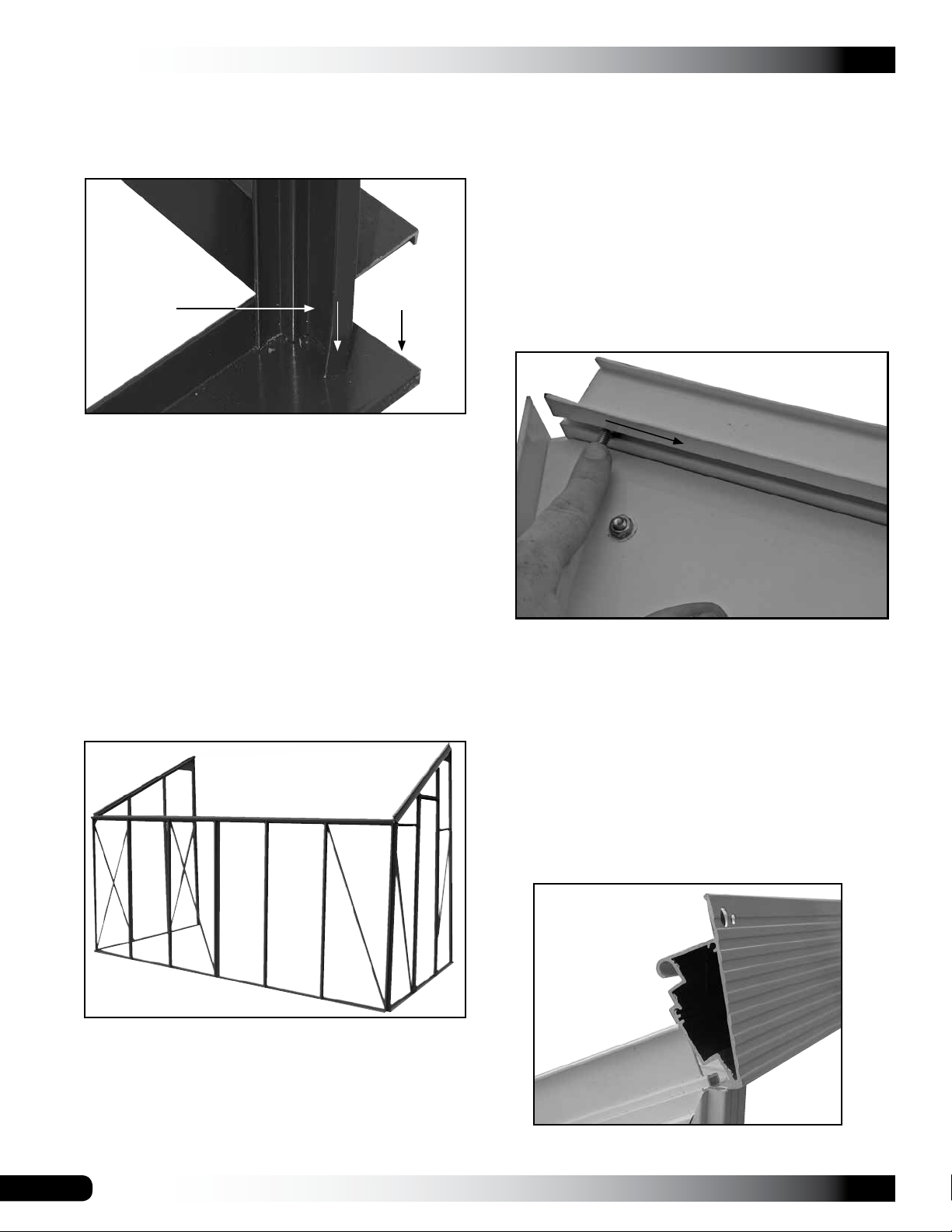
Photo below shows the corner of the greenhouse as
seen from the outside. End wall support is tight to the
top of the sidewall base rail.
End Wall
Base Rail
Sidewall
End Wall
Lower
Support
Base Rail
9. Verify that the end wall lower support is seated to the
top of the sidewall base rail.
10. Tighten the bolt to secure the sidewall base rail to the
end frame lower support.
11. Recheck all bolts to verify they are tight.
12. Repeat the procedure to connect the remaining gutter
rail ends to the end wall frame of the greenhouse to
complete the assembly of the greenhouse lower frame.
IMPORTANT: See the Exploded Frame diagram in the
Quick Start section if you are assembling the 104715
home-attached greenhouse. The 104715 frame
includes a 2-piece base rail for the sidewall, a
2-piece gutter rail, and a 2-piece ridge beam.
The ridge beam connects the two end wall frame
assemblies at the peak. Because it is the main support of
the roof framing, the ridge beam is installed before the roof
rafters.
For the 104715 greenhouse, consult the EXPLODED
FRAME COMPONENTS diagram in the Quick Start section
for important information before you continue.
Complete the following steps to install the ridge beam:
1. Choose a bolt and slide it into the bolt track of the
upper support for one end wall.
NOTE: Bolt will slide to the bottom of the track. Use a
small piece of tape to keep it near the peak where it is
used.
2. Locate roof parts and unwrap them.
3. Select the ridge beam (this will be the longest frame
member in the package) and position it between the
end wall frames at the peak. Assemble the beam for
the 104715 frame. See Exploded Frame diagram.
REMEMBER: Photos show the inside of the
greenhouse unless otherwise noted. All bolt tracks are
positioned to the inside of the greenhouse.
Photo above may be of a similar but different model.
13. To this point, all gutter rails are secured to the end wall
frame assemblies and all angle bracket bolts are tight.
14. Continue with installing the ridge beam of the roof.
16
View shows the ridge beam as seen from the outside
looking at the end wall frame.
Revision date: 01.01.16
RIDGE BEAM INSTALLATION (CONTINUED)
GROWSPAN™ ESTATE ELITE ATTACHED GREENHOUSES
INSTALL THE ROOF RAFTERS
View below shows the ridge beam as seen from the
inside looking at the peak of the end wall frame. Bolts
are slid into the pre-punched mounting slots in the
ridge beam.
Ridge Beam
The roof rafters are installed with the bolt tracks to the
inside of the greenhouse. Longer greenhouses (104713
and 104715) include a support (52) with double bolt tracks.
ATTENTION: Greenhouses 104713 and 104715 include a
main support (52) with a double track (see photo below);
begin with Step 1 and install this support (52) first.
For greenhouse 104711: If you are assembling the roof for
the 104711 greenhouse, begin with Step 11.
Complete the following steps as instructed:
1. Move the double track support (52) to the inside of the
assembled frame and locate the required bolts and
nuts.
NOTE: The double track support (52) is installed in
line with the double bolt track vertical support (14) of
the sidewall. The double track support (52) is installed
so it is attached to the sidewall vertical support (14) as
shown below. See Special Note on the Roof/Sidewall
Frame diagram in the Quick Start section if you are
assembling the 104713 greenhouse.
4. Add a nut to the bolt installed in Step 1 and slide the
bolt toward the peak and into the mounting slot of the
ridge beam.
5. Verify that the ridge beam is seated properly and
tighten the bolt.
6. Repeat the procedure to secure the remaining end of
the ridge beam.
2. Count the number of bolts needed to mount the 94,
100, and 101 brackets, and slide these into the bolt
track of roof support 52 and sidewall support 14.
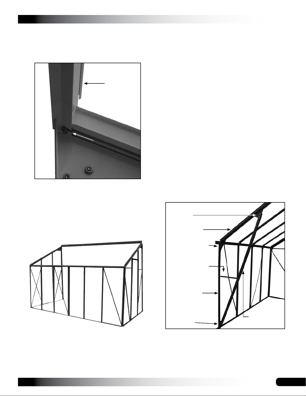
Upper Bracket
(101)
Double-Track
Roof Support
(52)
Angled Bracket
(94)
Horizontal
Support (103)
Double-Track
Sidewall
Support (14)
Lower Bracket
(100)
Diagonal Brace
(102)
7. With the ridge beam in place, install the roof rafters.
Revision date: 01.01.16
3. Add mounting bolts and one additional bolt to the
double-track sidewall support (14) for the horizontal
brace (103). Use tape to keep bolts from sliding out of
the track.
17
 Loading...