


GROWSPAN™ ESTATE ELITE GREENHOUSES
GrowSpan™
Estate Elite Greenhouses
©2016 GrowSpan
All Rights Reserved. Reproduction
is prohibited without permission.
Revision date: 01.01.16
Photo may show a different but similar model.
STK# DIMENSIONS
104609 11'-8" W x 8'-10" H x 16'-6" L
104611 11'-8" W x 8'-10" H x 24'-8" L
1
GROWSPAN™ ESTATE ELITE GREENHOUSES
YOU MUST READ THIS DOCUMENT BEFORE YOU
BEGIN TO ASSEMBLE THE SHELTER.
LOCATION
Choosing the proper location is an important step before
you begin to assemble the structure.
The following suggestions and precautions will help you
determine whether your selected location is the best
location.
• Never erect the structure under power lines.
Thank you for purchasing this GrowSpan™ greenhouse.
When properly assembled and maintained, this product will
provide years of reliable service. These instructions include
helpful hints and important information needed to safely
assemble and properly maintain the greenhouse. Please
read these instructions before you begin.
SAFETY PRECAUTIONS
• Wear eye protection and gloves when handling panels
and frame parts.
• Frame is metal. Use a portable GFCI when working
with power tools and cords.
• Do not climb on the greenhouse or framing during or
after construction.
• Do not occupy the greenhouse during high winds,
tornadoes, or hurricanes.
• Provide adequate ventilation if the structure is
enclosed.
• Do not store hazardous materials in the greenhouse.
• Provide proper ingress and egress to prevent
entrapment.
ANCHORING INSTRUCTIONS
• Identify whether underground cables and pipes are
present before preparing the site or anchoring the
structure.
• Location should be away from structures that could
cause snow to drift on or around the building.
• Do not position the greenhouse where large loads
such as snow and ice, large tree branches, or other
overhead obstacles could fall.
• Always check local building codes before you begin.
SITE
After choosing a location, proper preparation of the site is
essential. The following site characteristics will help ensure
the integrity of the structure.
• A level site is required. The site must be level to
properly and safely erect and anchor the structure.
• Drainage: Water draining off the structure and from
areas surrounding the site should drain away from the
site to prevent damage to the site, the structure, and
contents of the structure.
WARNING: The individuals assembling this structure
are responsible for designing and furnishing all
temporary bracing, shoring and support needed during
the assembly process.
Prior to assembling this greenhouse, please read the
MUST READ document included with the shipment.
WARNING: The anchor assembly is an integral part
of the greenhouse construction. Improper anchoring
may cause greenhouse instability and failure of the
structure. Failing to anchor the greenhouse properly
will void the manufacturer’s warranty and may cause
serious injury and damage.
IMPORTANT! INVENTORY THE PARTS
1. Open one box and use the Bill of Material included in
that box to inventory the contents. See Page 39 for Box
9-4 (104611) or Box 7-4 (104609) for cresting parts.
2. Return all parts and the Bill of Material to the box and
repeat the procedure for all remaining boxes.
3. Call Customer Service at 1.800.245.9881 to report
any missing parts before you begin assembling the
greenhouse.
2
For safety reasons, those who are not familiar with
recognized construction methods and techniques must
seek the help of a qualified contractor.
ASSEMBLY NOTE
The assembly of this greenhouse is not complex; however,
it does take time and additional assistance. For best
results, read through these instructions before you begin to
get an overview of the entire assembly. Then, follow these
instructions as presented.
Examine all diagrams and photos and verify that you have
selected the proper parts from the correct box or boxes. Do
not mix parts from different boxes. When checking parts,
place the parts back into the same box they were removed
from and continue with the next box.
Revision date: 01.01.16
ASSEMBLY PROCEDURE
GROWSPAN™ ESTATE ELITE GREENHOUSES
GREENHOUSE PARTS
Following the instructions as presented will help ensure
the proper assembly of your greenhouse. Failing to follow
these steps may result in an improperly assembled and
anchored greenhouse and may void all warranty and
protection the owner is entitled.
The steps outlining the assembly process are as follows:
1. Verify that all parts are included in the shipment. Notify
Customer Service for questions or concerns.
2. Read these instructions and all additional
documentation included with the shipment before you
begin assembling the greenhouse.
Use these instructions and the Bill of Material (inside
each box) when assembling the greenhouse.
3. Gather the tools, bracing, ladders (and lifts if
applicable), and assistance needed to assemble the
greenhouse.
4. Re-evaluate the location and site based on the
information and precautions presented in the
documentation included with the shipment.
5. Lay out the site (if this has not been completed).
All greenhouse sections (e.g., roof, sides, end walls, etc.)
are shipped in individually numbered boxes. The quantity of
boxes may differ depending on the greenhouse.
To prevent mixing the parts while assembling the
greenhouse, select the boxes as instructed and open that
box only and assemble its contents.
OPEN BOXES AS INSTRUCTED TO PREVENT MIXING
OF THE CONTENTS.
NOTE: Some photos and diagrams throughout these
instructions may show a greenhouse with slightly different
dimensions, color, or design. The assembly procedures
are identical regardless of these differences. Notable
differences are addressed.
For a quick overview of this greenhouse, consult the
diagrams in the Quick Start section near the back of these
instructions.
Those not familiar with the assembly of similar structures
and the use of common hand tools must seek the
assistance of someone with such experience.
6. Assemble the base frame (additional purchase
required) and greenhouse components in the order
they are presented in these instructions.
7. Anchor the greenhouse as instructed.
8. Read the greenhouse care and maintenance
information at the end of these instructions.
9. Complete and return all warranty information as
instructed.
REQUIRED TOOLS
The following list identifies the main tools needed to
assemble the shelter. Additional tools and supports may be
needed depending on the structure, location, and
application.
• Tape measure or measuring device
• Metric and standard wrench set (or ratchet and socket
set)
• Phillips screwdriver
• Needle-nose pliers
WARNING: Do not allow the polycarbonate panels to
remain in direct sunlight until they are installed. Doing
so will cause the protective film to become difficult if not
impossible to remove.
Consult Page 40 for additional polycarbonate
information. And, Step 10 on that page, for "how to use
vent tape" (additional purchase required) information
before installing any polycarbonate panel.
PART IDENTIFICATION NUMBERS
All main parts include a stamped ID number. Use this
number when selecting the required parts during the
assembly.
1617
• Ladders and/or work platforms
• Caulk gun for silicone application
• Utility knife
Revision date: 01.01.16
1617
NOTE: The locations of the part numbers on the
components may vary. Refer to the Bill of Materials shipped
within each box for a description of each part.
3
GROWSPAN™ ESTATE ELITE GREENHOUSES
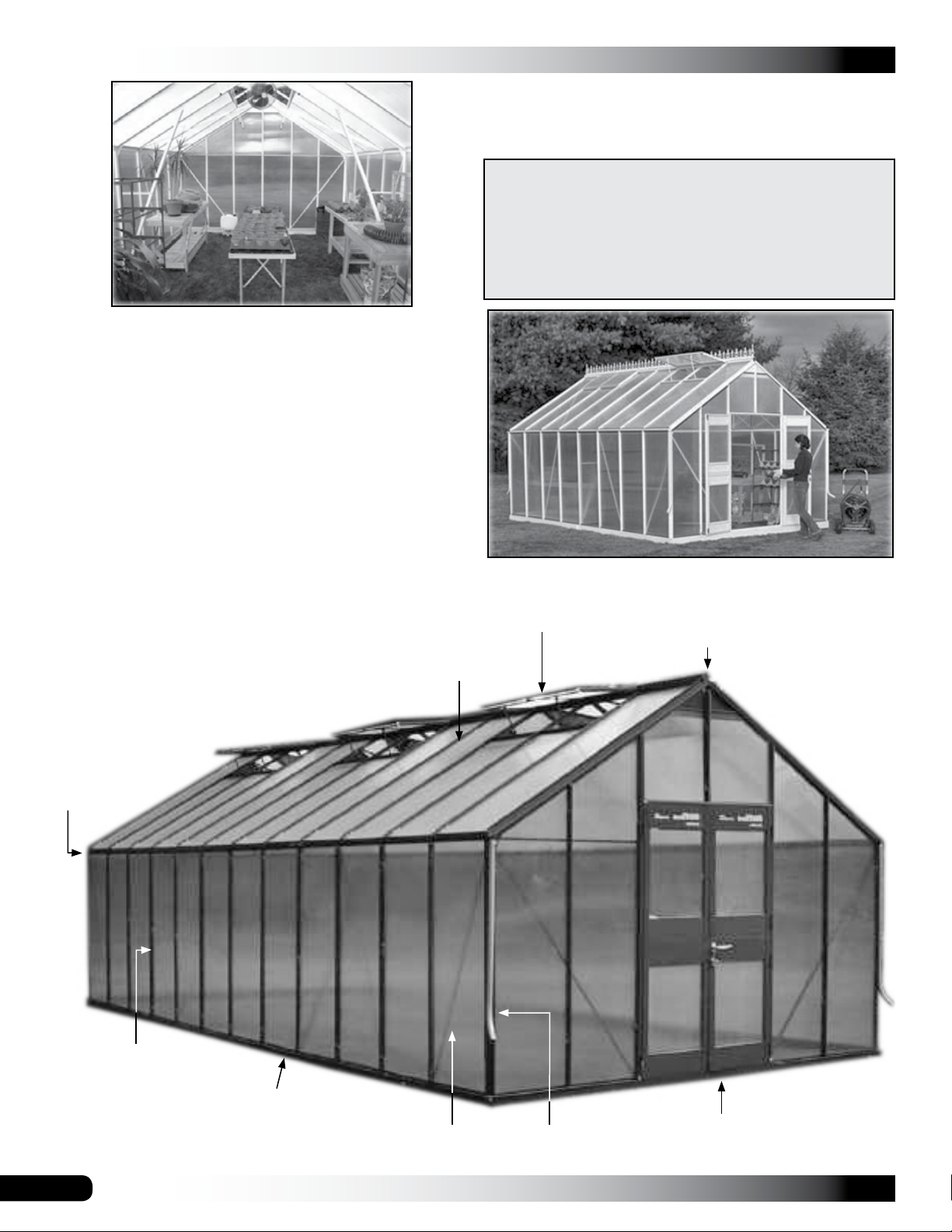
OVERVIEW
This section is an overview of the process for assembling
your Elite Greenhouse. See illustration below to identify
main parts of greenhouse.
1. Locate the required parts for each assembly procedure.
2. Preassemble the base frame (additional purchase
required), end walls, and side walls as instructed.
3. Assemble the frame and install the ridge beam, rafters,
vents, and vent panels.
Estate Elite Greenhouses
ATTENTION: TO AVOID TWISTING OFF OR DAMAGING
THE FASTENERS, DO NOT OVERTIGHTEN.
FOR YOUR CONVENIENCE, ADDITIONAL FASTENERS
CAN BE FOUND IN THE "EXTRA PARTS" BAG OR BOX.
REFER TO THE BILL OF MATERIALS FOR A LIST OF
THE FASTENERS CONTAINED IN THAT BAG OR BOX.
4. Square and anchor the greenhouse.
5. Assemble and attach doors and install door panels.
6. Install all remaining polycarbonate panels.
7. Attach drain pipes and remaining door hardware.
Gutter Rail
Rafters
NOTE: Model shown below may differ slightly from the actual Elite
model. No cresting is shown.
Vent
Ridge Beam
Vertical Support:
Side Wall
4
Base Rail
Diagonal
Strut
Drain Pipes
Double Door
Revision date: 01.01.16
BASE FRAME ASSEMBLY (OPTIONAL PURCHASE)
The base frame assembly provides a level, square surface
on which to set the greenhouse frame. It is strongly
recommended that you use this base.
The optional base (additional purchase required) is
assembled and squared, its posts set into the ground.
It is then anchored in place using ground posts or
other approved anchoring methods described in these
instructions.
This base is an optional purchase. Contact your sales
consultant at 1-800-245-9881 to purchase the base.
The following steps describe how to assemble the optional
base frame for the greenhouse.
1. Unpack the base kit to identify the parts.
NOTE: The base is assembled upside down and then
is flipped when it is positioned on the site.
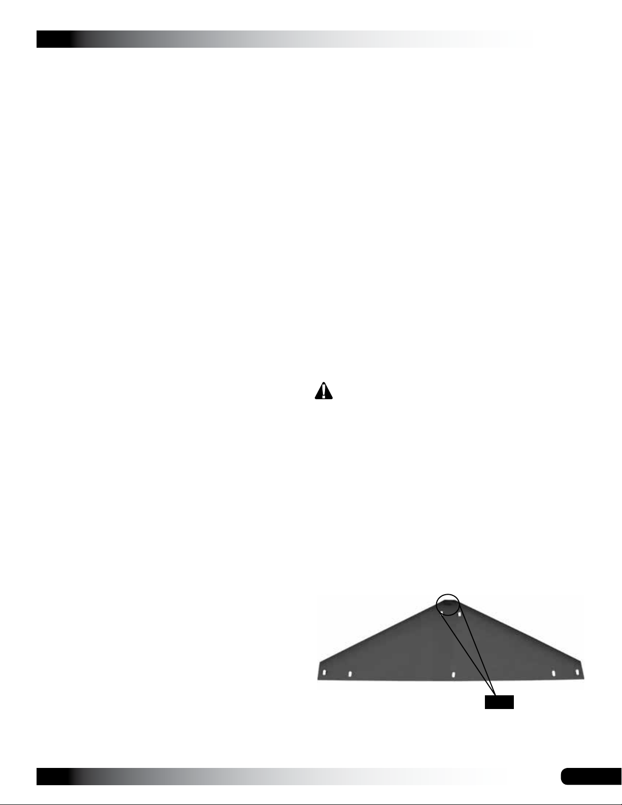
2. Identify the base channel lengths used for the ends
(width) and the sides (length).
GROWSPAN™ ESTATE ELITE GREENHOUSES
Cut these only if you plan to place the frame, and
ultimately the greenhouse, on a concrete slab.
Leg portion of
IMPORTANT:
Dashed line shows
where to cut when
removing the
leg for use on
concrete only.
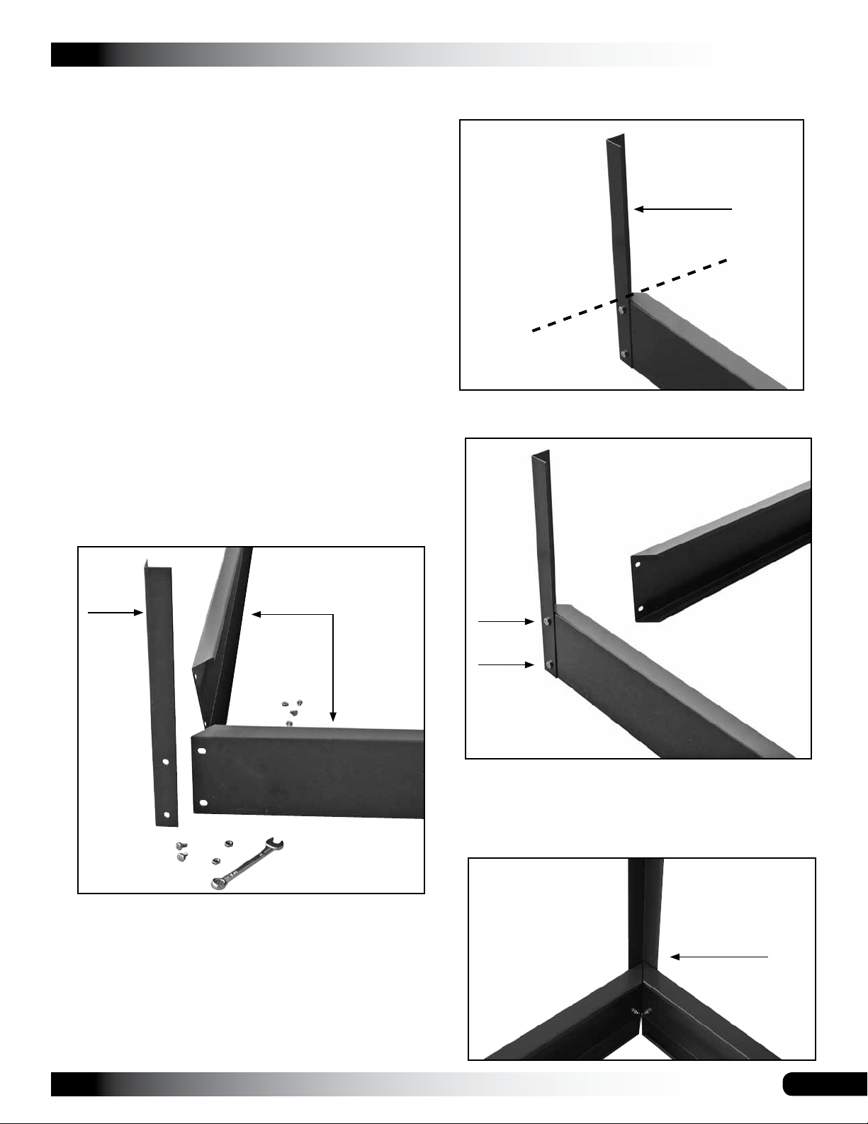
4. Insert two bolts through the pre-drilled holes in the post
and one base channel and add the nuts.
frame support post
3. Select the first frame support post and the required
nuts and bolts and place these at one corner of the
base.
Support
Post
Base
Channels
ATTENTION: If you plan to place the base on a
concrete slab or patio, you must remove the "leg"
portion of the frame support posts. Before you
assemble the base as shown below, cut the frame
support posts so they are the same length as the base
channel is wide.
NOTE: Do not tighten the bolts at this time.
5. Select the remaining bolts and repeat the previous step
to attach the remaining base channel to the support
post.
Support Post
Revision date: 01.01.16
5
GROWSPAN™ ESTATE ELITE GREENHOUSES
BASE FRAME ASSEMBLY (CONTINUED)
SQUARE THE BASE
6. Verify that the post is straight and tighten the bolts
7. Repeat the procedure to attach the remaining support
posts to the base channels.
For strength, position short base sections (if equipped)
diagonally from each other as shown.
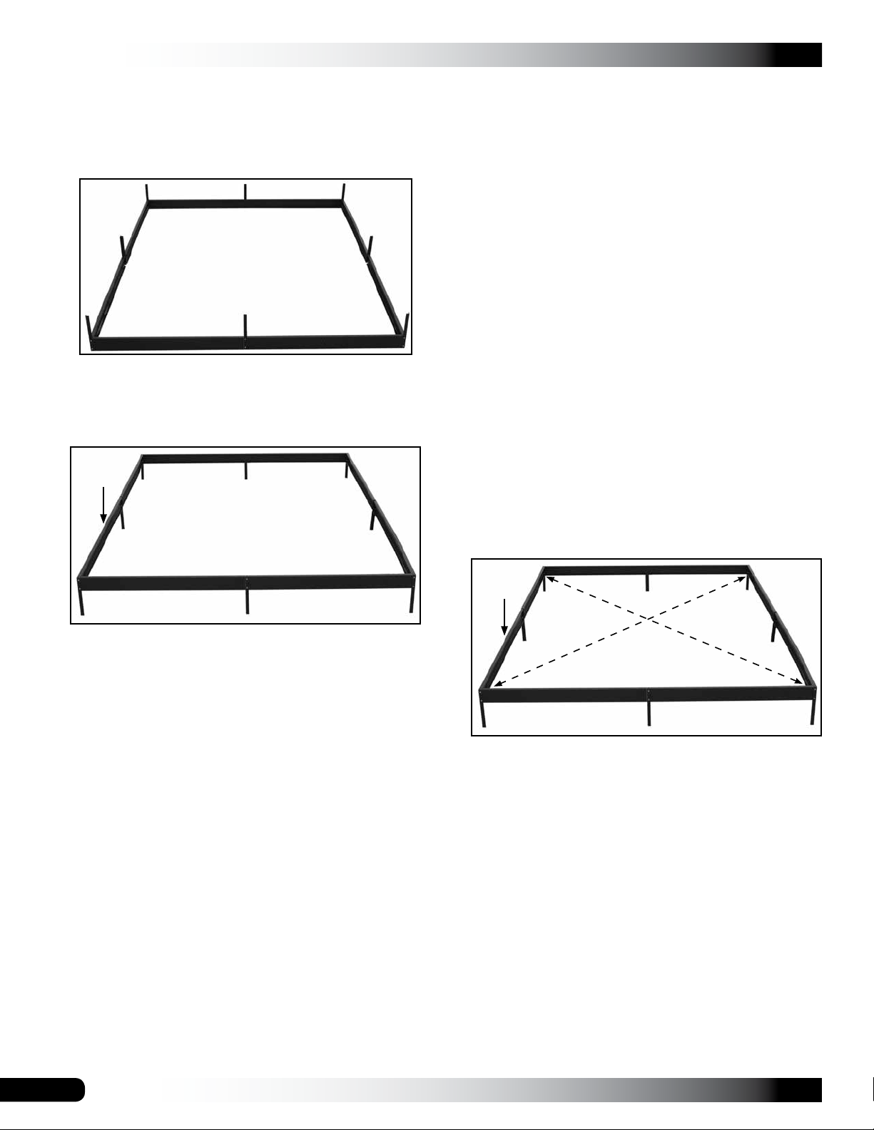
8. After the frame is assembled and all bolts are tight, flip
the base over and set it on the site.
Top of
base
Before the support posts of the base are driven into the
ground and before the assembled greenhouse frame is
set on and secured to the base, you must square the base
assembly and anchor the base to the site.
ATTENTION: If you are setting the base and greenhouse
on a patio or concrete slab, set the assembled base on site
and continue with the greenhouse assembly procedures
that follow. Do not square the base at this time.
This base and greenhouse require a level site. Before
setting the base or greenhouse frame (or both) in place,
you must level the site.
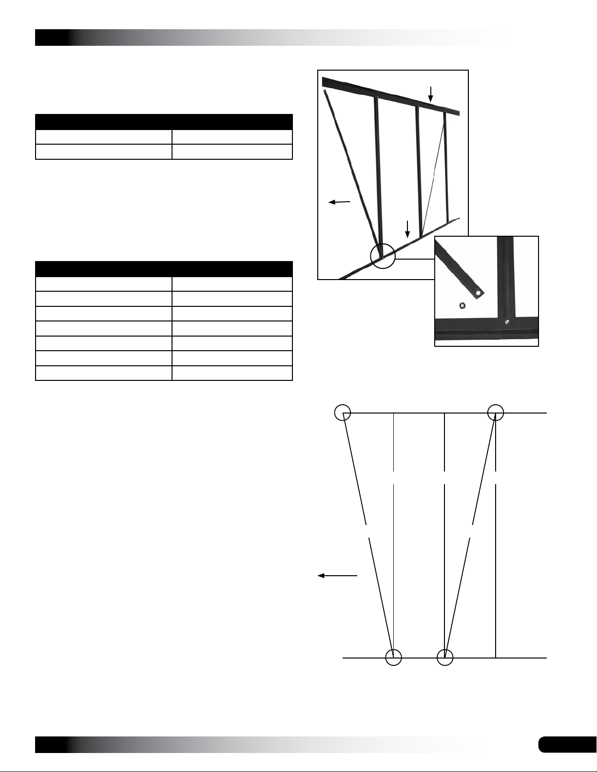
The easiest way to square the base is to measure
diagonally from corner to corner.
Complete these steps:
NOTE: The following procedure describes how to square
the base on a prepared site and drive the base support
posts into the ground.
1. Position the assembled base on the site as shown
below.
9. Continue with the next procedure.
NOTE: If additional legs are present, use the longer
bolts included with the kit to secure the legs to the
frame.
PACKING LIST NOTE (OPTIONAL BASE FRAME ONLY)
Some packing lists included with the optional base kit may show
J-clips as an included item. These J-clips are no longer used and
are not included in the shipped items.
The self-tapping screws are now included and are used instead.
Consult the anchoring instructions within this document for
additional information.
2. Measure diagonally from corner-to-corner.
Top of
base
NOTE: The frame is square when both measurements
are the same.
3. When the frame is square, tap the support posts into
the ground to set the frame in place and recheck the
measurements.
NOTE: Place a block of wood on top of the base
channel and support post and hammer on the wood to
protect the frame when driving the posts into place.
4. Continue to drive the posts to the desired depth.
NOTE: Use a level (or string a line) to verify that the
base remains level when set into the ground
5. After setting the base on the site, continue with the
greenhouse assembly.
6
Revision date: 01.01.16
ASSEMBLE THE END WALL FRAMES
The greenhouse has two end walls: one is the door end
and one is the non-door end.
GROWSPAN™ ESTATE ELITE GREENHOUSES
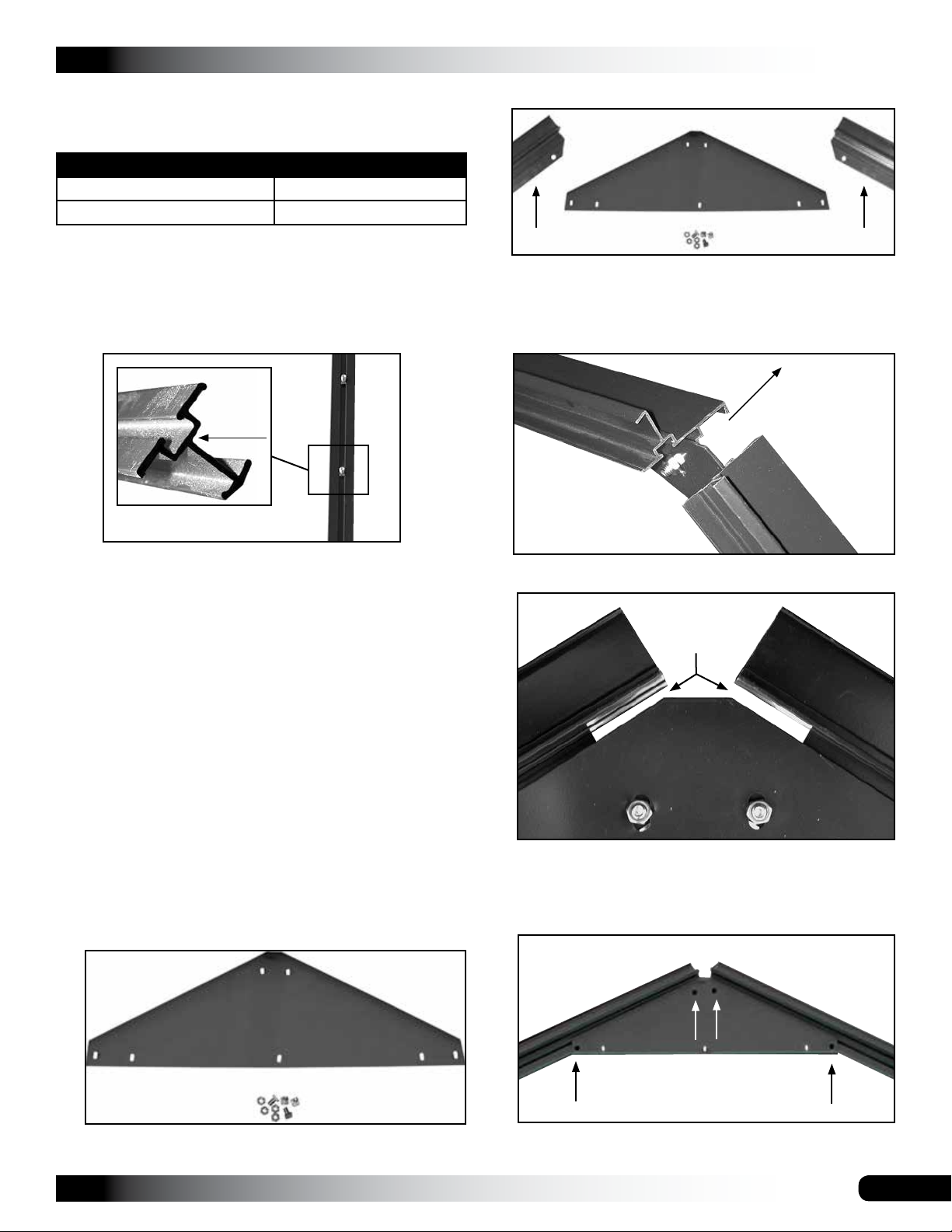
3. Locate the two upper supports for the end wall.
Greenhouse Sku Number Open this box:
104609 C/No. 7-1
104611 C/No. 9-1
For the best results and to prevent mixing parts, assemble
each end wall separately as described below. All bolt tracks
in the frame members are installed to the inside of the
greenhouse. All diagrams and individual photos shown in
these end wall instructions show the inside surface of the
frame unless otherwise noted.
Bolt Track
Photo shows vertical frame member for end walls. The bolt
track is installed to the inside of the greenhouse.
IMPORTANT: To prevent loosing parts, assemble all
frame components on a flat surface. A concrete driveway
or a garage floor works best. As you assemble the frame
sections, the inside of the frame will face up as shown in
the photos that follow.
1617
1616
1615
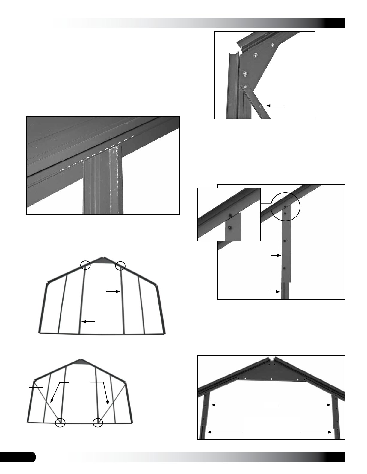
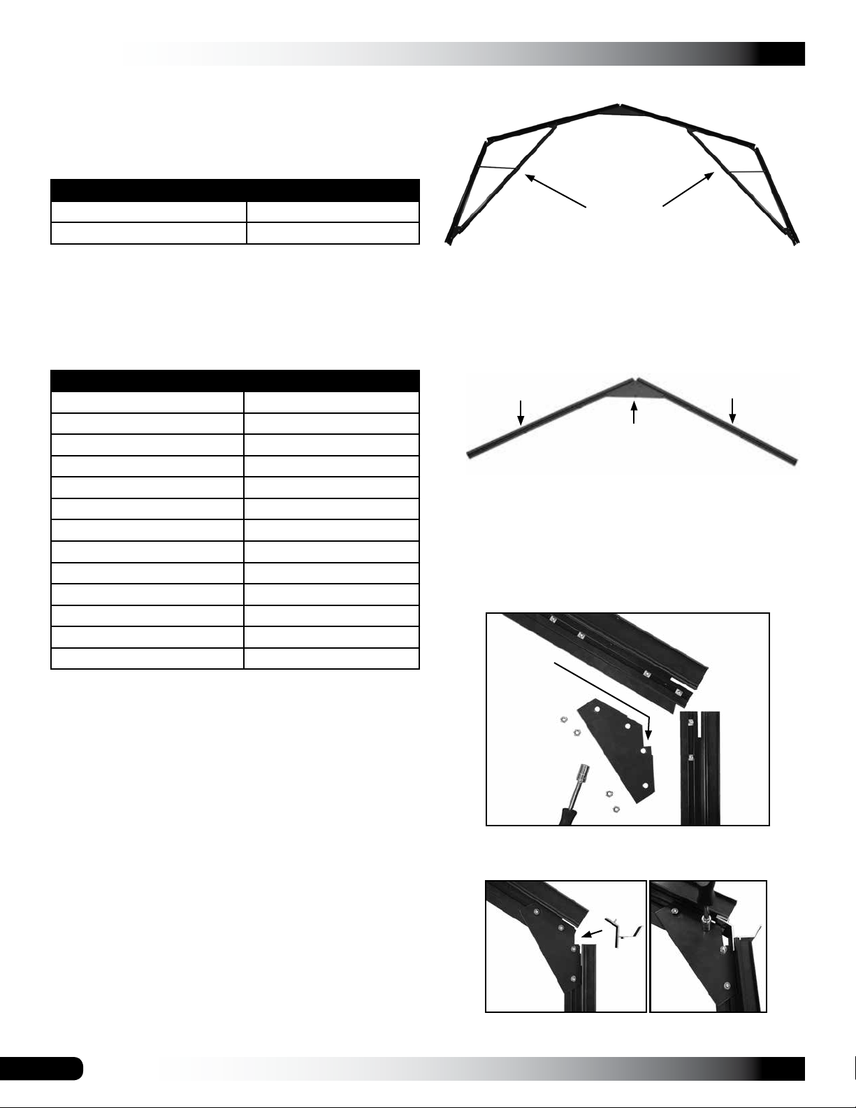
The upper supports include pre-drilled holes, bolt
tracks, and a beveled end.
4. With the upper supports positioned as shown below,
secure the 1617 bracket to the supports.
To the outside of
the greenhouse
1616
1615
View looking down on the assembled upper supports.
1616
Slots
1615
Complete the following steps to assemble the first end wall
frame. Consult the End Wall Diagrams near the back of
these instructions for part identification before you begin.
Assemble the door end first.
1. Open the package for your greenhouse. (See above
note if needed.) This package includes the parts to
assemble the end wall frames. Consult the End Wall
Diagrams for part identification.
2. Locate the top bracket used to join the upper supports
to each other at the peak of the end wall.
1617
NOTE: The holes in the top bracket are oblong as
shown.
1617
Verify that the slot at the top of each upper support is
fully visible before you tighten the bolts to secure the
1617 angled bracket to the upper supports. See the
photo above.
1616
1615
Joined upper supports as seen from the inside of the
greenhouse.
Revision date: 01.01.16
7
GROWSPAN™ ESTATE ELITE GREENHOUSES
ASSEMBLE THE END WALL FRAMES (CONTINUED)
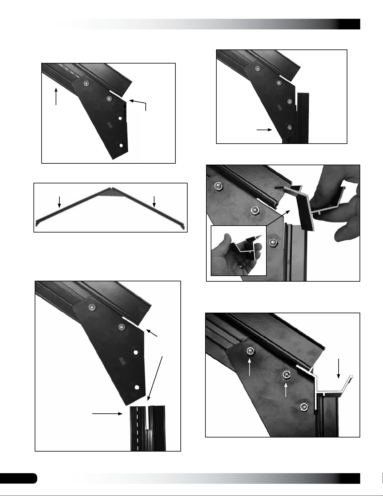
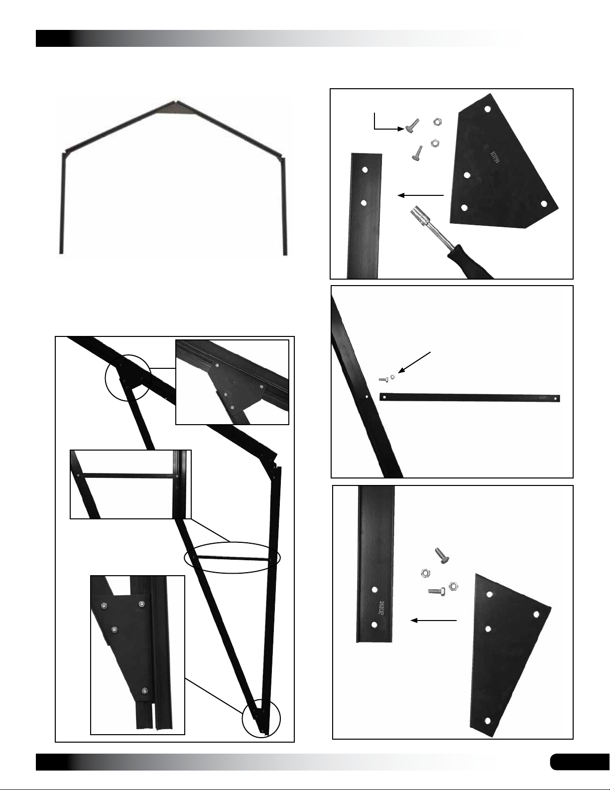
5. Locate one (1) 1618 angled bracket and attach it to the
end of one upper support. Do not tighten bolts.
8. Slide two (2) bolts into the bolt track and install the
1618 bracket as shown. Do not tighten bolts.
Verify that
the slots are
aligned as
shown.
1618
Upper Support
1615
1618
Position the
slot in the
upper support
as shown.
6. Locate another angled bracket and attach it to the end
of the other upper support. Do not tighten bolts.
1616
Assembled Upper End Wall Frame
1615
The assembled upper end wall frame is shown above
and includes the top bracket, two (2) angled brackets,
and two (2) upper supports.
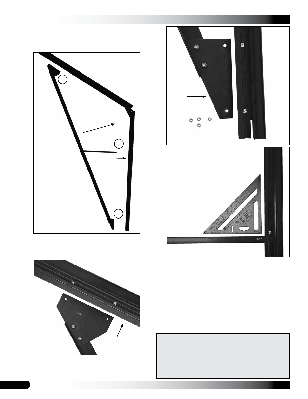
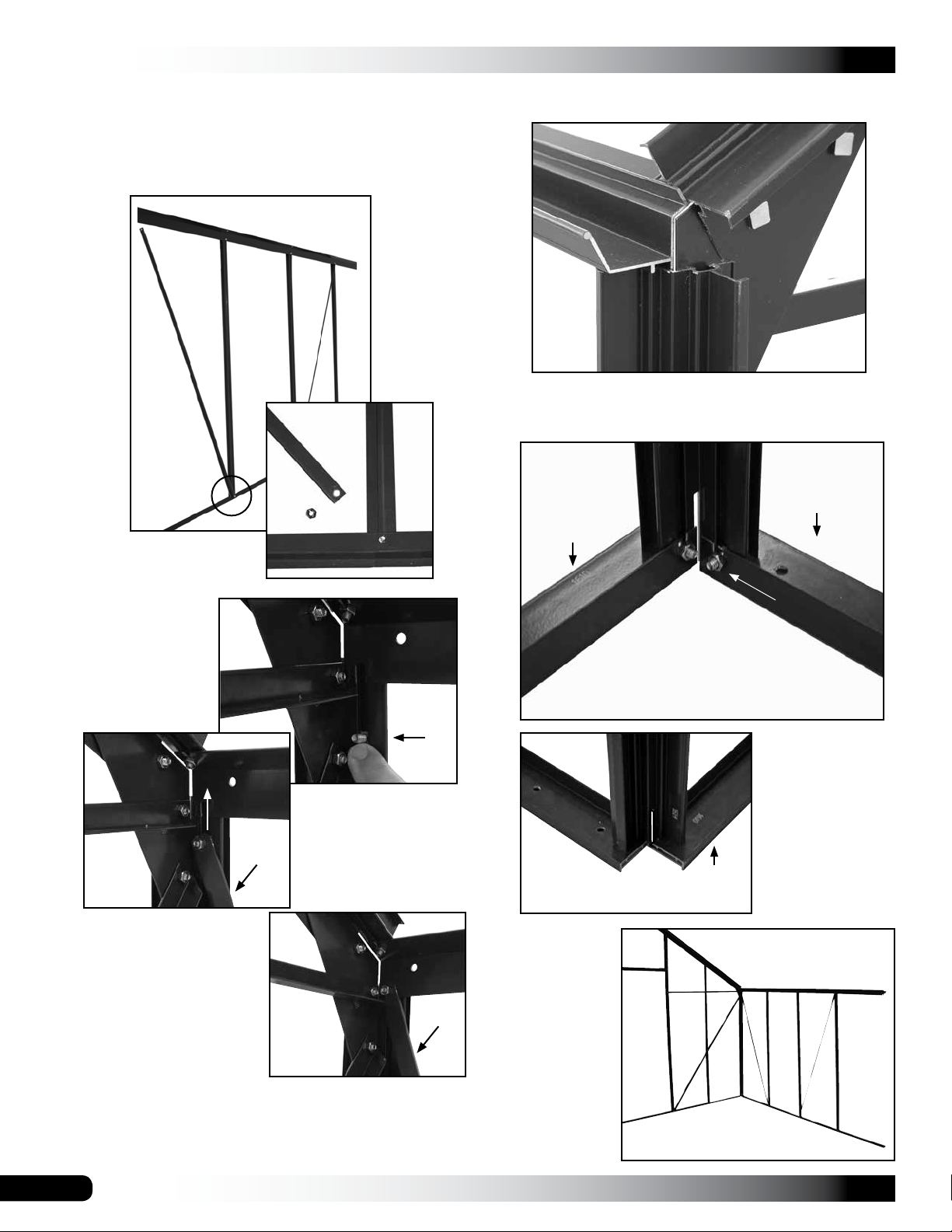
7. Select one (1) 1614 lower support and position it as
shown below. Align the slots in each frame member.
Nuts will be
removed when the
bracing is installed.
9. Verify that the four bolts are loose and place the
template into position as shown in the photos below.
template
ATTENTION: The template is used to set the proper
clearance for the gutter rail. The template slides into
the slots in each frame member.
The dashed line
shows the bolt
track location.
Slide mounting
bolts into this track
to secure bracket.
8
Align the
slots.
Template
1614
1614
10. With the template in position, tighten the bolts to secure
the bracket to the upper frame member of the end wall.
See the arrows above.
Revision date: 01.01.16
ASSEMBLE THE END WALL FRAMES (CONTINUED)
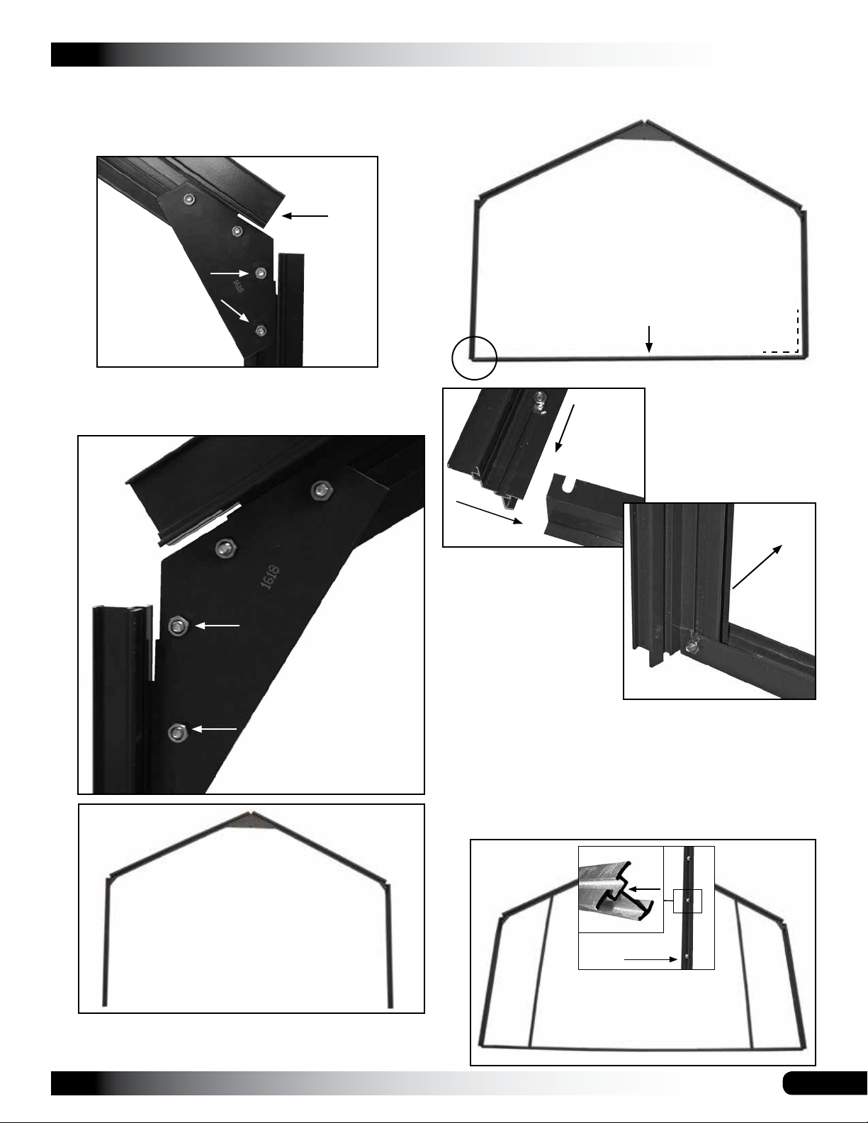
11. Slightly tighten the lower two bolts and remove the
template. These bolts are loosened in a later step to
install the end wall horizontal and diagonal bracing.
Clearance
set using the
1615
template.
GROWSPAN™ ESTATE ELITE GREENHOUSES
13. Locate the base rail (1610) for the end wall and attach
it to each of the lower supports as shown below.
1614
1614
12. Repeat the steps to attach the other 1614 lower end
wall support and to set the gutter rail clearance using
the template as previously described.
1616
1614
ATTENTION: Do
not fully tighten the
lower bolts. These
are loosened and
retightened after the
bracing is installed
in a later procedure.
Base Rail
1610
A
90°
A
ATTENTION: ALL
DIAGRAMS AND
PHOTOS SHOW THE
ASSEMBLY FROM THE
INSIDE OR BOLT TRACK
SIDE OF THE FRAME
DURING ASSEMBLY.
Inside
ATTENTION: Seat each lower support tight against the
top surface of the base rail.
14. Verify that each lower-support-to-base-rail connection
is square and tighten the bolts.
outside
1616
1614 1614
1615
Photo above shows the assembled end wall up to this
point. View shows the inside surface of the frame.
Revision date: 01.01.16
15. Refer to the End Frame diagram and select the two (2)
end wall vertical supports shown below.
Bolt
Track
Vertical Support
1611-2
1611-1
9
GROWSPAN™ ESTATE ELITE GREENHOUSES
ASSEMBLE THE END WALL FRAMES (CONTINUED)
16. Slide four (4) bolts into the track of each vertical
support and attach the top of each support to the upper
end wall supports and the bottom of each support to
the base rail. Do not tighten these bolts at this time.
ATTENTION: The remaining two (2) bolts in each
vertical—those between the top and bottom bolts—are
used to secure the short horizontal braces and the
diagonal struts. See the End Frame diagrams if
needed.
B
Diagonal
Strut (1613)
1615
Dashed line shows
the beveled top of
the end wall frame
members.
View shows the
end wall from the
outside.
Install the beveled end of the frame member at the top
and with the angle of the end wall upper supports.
17. Select the next two (2) vertical supports for the end wall
and insert seven (7) bolts into the bolt track of each
vertical. (Door end frame only.)
1612-1
ATTENTION: Do not fully tighten the bolts at this time.
20. Select the 16110 bracket and attach it as shown below
using three (3) of the bolts remaining in the bolt track.
Tighten the bolts to secure the 16110 bracket to the
end wall frame.
21. Repeat the step and attach the remaining 16110
bracket to the remaining vertical frame member.
Photo shows the
16110
1612-2
installed 16110
bracket as seen
from inside the
frame.
1612-2
18. Attach each vertical to the upper supports of the frame.
See the circles above. Do not tighten bolts.
NOTE: After
B
1613
completing this
step, each vertical
from the previous
step should be
attached at the
top and bottom
and five (5) bolts
should remain
between the top
and bottom bolts.
19. Add a diagonal strut to the frame and install the bottom
bolts. See the circles above for bolt location.
10
IMPORTANT: At this point, two (2) bolts should remain
in each of the vertical frame members. These bolts are
used in the next steps.
22. Slide one of the two remaining bolts in the frame
member up to the bottom of the 16110 bracket. Repeat
this step for the remaining vertical frame member.
16110
Slide a bolt up to here
in each of the bolt
tracks (Step 22).
Revision date: 01.01.16
ASSEMBLE THE END WALL FRAMES (CONTINUED)
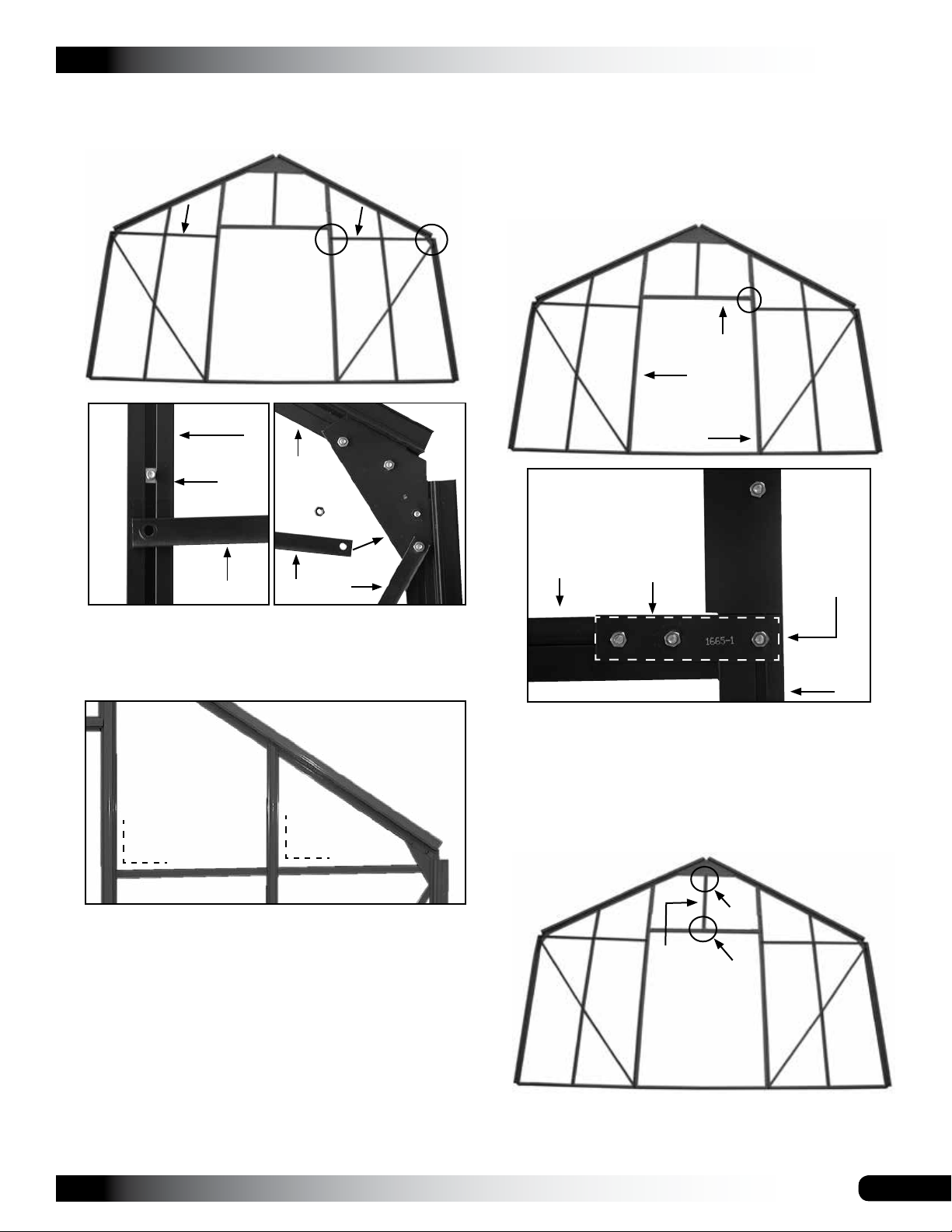
23. Locate the horizontal braces and attach these to the
end wall frame. Do not use the bolt from Step 22.
D
C
GROWSPAN™ ESTATE ELITE GREENHOUSES
26. Locate the 1665 header and slide five (5) bolts into the
bolt track.
27. Attach a 1665-1 flat bracket to each end of the 1665
header. Do not fully tighten the bolts at this time.
28. Attach the header and flat brackets between the
vertical frame members as shown below.
E
1665
1612-2
C
ATTENTION: Use a carpenter's square or similar tool
to verify that a 90° angle is maintained at the point
where the horizontal brace is attached to the vertical
frame members of the end wall. See example below.
1612-1
Bolt
1619-1
1615
1619-1
1613
C
90°
90°
D
D
1612-1
E
16110
1665
NOTE: Use the final bolt (Step 22) in each of the
vertical frame members to secure each 1665-1 bracket.
Do not tighten these bolts at this time.
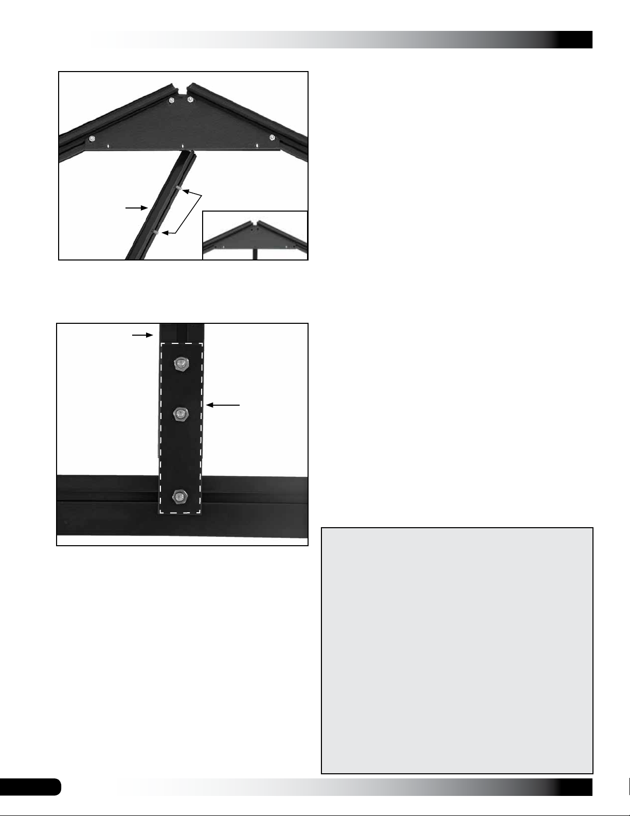
29. Locate the 1612-3 vertical frame member and attach it
between the header and the peak of the end wall.
1665-1
Bolt from
Step 22
1612-1
24. Tighten the bolts to secure the horizontal brace to the
end wall frame.
25. Repeat the steps to install the remaining brace.
NOTE: At this point, one bolt should remain unused in
each of the two frame members. This bolt is used to
secure the door header (1665) to the end wall frame.
Verify that one (1) bolt is present to secure each end of
the 1665 header. If you need to install or reposition a
bolt, loosen the horizontal brace bolts as needed, make
the necessary adjustments, and retighten.
Revision date: 01.01.16
F
1612-3
G
NOTE: Consult the photos on the following page for
additional details.
11
GROWSPAN™ ESTATE ELITE GREENHOUSES
ASSEMBLE THE END WALL FRAMES (CONTINUED)
Space is reserved for customer notes.
F
1616
Bolts
1612-3
Do not fully tighten the bolts. The header (1665) and
the vertical frame member (1612-3) are adjusted and
secured when the doors are installed later in these
instructions. Bolt should be snug to secure the header.
1612-3
1615
G
1665-1
1665
30. After completing the frame for the doors, consult
the end wall diagram for the non-door end of the
greenhouse and repeat the procedure to assemble that
end wall frame.
ATTENTION: The remaining end wall frame does not
include an upper door frame member. In addition, the
small horizontal braces of the first end wall frame have
been replaced by a single, longer horizontal brace.
Keep these changes in mind as you complete the
assembly of the remaining end wall frame.
Consult the diagram near the back of these instructions
to view the non-door end wall components.
31. After assembling the end wall frame for the non-door
end, set both end wall frames aside and continue with
the sidewall assembly procedure that follows.
12
EXTRA PARTS PROVIDED FOR GREENHOUSE
ATTENTION: TO AVOID TWISTING OFF OR DAMAGING
THE FASTENERS, DO NOT OVERTIGHTEN.
FOR YOUR CONVENIENCE, ADDITIONAL FASTENERS
AND PLASTIC MOLDING CAN BE FOUND IN THE
"EXTRA PARTS" BAG OR BOX.
REFER TO THE BILL OF MATERIALS FOR A LIST OF
THE FASTENERS AND MOLDING CONTAINED IN THAT
BAG OR BOX.
The plastic profile can be trimmed to the required length if
a piece is misplaced or damaged during installation.
IMPORTANT: Consult the "extra parts" for items you
need before contacting customer service to request a
replacement for damaged or missing parts or fasteners.
Revision date: 01.01.16
SIDEWALL ASSEMBLY: First Two (2) Sections
1632-4
1630-4
GROWSPAN™ ESTATE ELITE GREENHOUSES
Diagrams and Photos for Sidewall Assembly
After both end wall frames are assembled, locate the next
box (identified below) for your greenhouse and assemble
the first two sections of sidewall framing.
Greenhouse Sku Number Open this box:
104609 C/No. 7-2
104611 C/No. 9-2
For the best results and to prevent mixing parts, assemble
each side wall separately as described. All bolt tracks
in the frame members are installed to the inside of the
greenhouse. All diagrams and individual photos shown in
these sidewall instructions show the inside surface of the
frame unless otherwise noted.
Required parts for the first two (2) sidewall frames:
Part Number Quantity
1631 6
1632-4 2
1630-4 2
1633 4
Square-Head Bolts (short) See frame diagram.
Square-Head Bolts (long) See frame diagram.
Nuts for all bolts Same as bolt quantity.
HINT: For best results, select the parts using the table
above and the sidewall frame diagrams. Position all
parts on a flat surface and arrange them according to the
sidewall diagram. After the parts are in place, take the
required bolts and connect the pieces.
Gutter Rail 1632-4
Consult the full
sidewall frame
diagrams near
the back of these
instructions
for additional
information.
1630-4
Toward
the End
Frame
The diagonal shown to the
right can be installed now
or when the sidewall frame
is attached to the end wall
frame. Do not fully tighten
this bolt at this time.
Base
Rail
The circles show where to use the longer, square-head
bolts. The circle marked with an A (below) shows the long
bolt that is slid into the end wall bolt track during the frame
assembly.
A
The following steps describe assembling two identical
sidewall frames. Complete these steps:
1. Open the box (indicated above) for your greenhouse
and, using the table above, gather the parts to
assemble the first two (2) sidewall sections.
ATTENTION: PLACE ALL OTHER PARTS BACK
INTO THE BOX UNTIL THEY ARE NEEDED LATER
DURING THE ROOF ASSEMBLY PROCEDURE.
2. Use the following photos and diagrams to layout and
connect the sidewall frame components.
NOTE: It may be necessary to remove or loosen bolts
(used during this procedure) when the sidewall frames
are attached to the end wall frame.
The two side frames should match when the
assembled frames are placed side-by-side with the bolt
tracks together.
3. After assembling the first two (2) sidewall frame
sections, set them aside and continue with the next
procedure to assemble a main frame mid rafter.
163116311631
1633 1633
This edge will
be attached to
the end wall
with the door
frame.
ATTENTION: View of the sidewall is from the inside (or bolt
track side) for one side frame and from the outside for the
other side frame. When placed together with the bolt tracks
inward, the frames match and the diagonals will line up.
Revision date: 01.01.16
13
GROWSPAN™ ESTATE ELITE GREENHOUSES
ASSEMBLE MAIN FRAME MID RAFTER
Assembled Main Frame Mid Rafter
The mid rafter (or rafters) for the greenhouse are positioned
between the individual sidewall frame sections. Consult the
tables that follow and the diagrams to assemble the mid
rafter (or rafters) for your greenhouse.
Greenhouse Sku Number Open this box:
104609 C/No. 7-3
104611 C/No. 9-3
For the best results and to prevent mixing or misplacing
parts, remove the necessary parts (identified below) from
the box and assemble the mid rafter as described.
All diagrams and photos shown in this procedure show the
inside (or bolt-track) surface of the mid rafter unless noted.
Select these parts to assemble one (1) mid rafter:
Part Number Quantity
1614 2
1615 1
1616 1
1694 2
1617 1
16100 2
16101 2
16102 2
16103 2
Template See end frame steps.
Hex-Head Bolts 10
Square-Head Bolts (short) See photos.
Nuts for all bolts Same as bolt quantity.
HINT: For best results, position all parts on a flat surface
and arrange them according to the photos. After the parts
are in place, take the required bolts and connect the parts.
The following steps describe assembling one (1) mid rafter:
1. Open the box (indicated above) for your greenhouse
and, using the table, gather the parts to assemble the
mid rafter.
ATTENTION: PLACE ALL OTHER PARTS BACK INTO
THE BOX UNTIL THEY ARE NEEDED.
1616
1614
Mid Rafter Diagonal Bracing
1615
1614
NOTE: The mid rafter is built using the same upper and
lower supports found in the end wall framing.
Complete these steps to assemble the mid rafter.
1. Using Steps 2-4 of the Assemble the End Wall Frames
procedure (Page 7), connect the upper mid rafter
components.
1616
1617
Assemble Upper Mid Rafter
1615
2. Slide four (4) bolts into the bolt track of one upper
support. See the next photo. Two bolts are used to
attach the diagonal bracing in a later procedure.
3. Using two of the bolts (Step 2), attach the 1694 bracket
to the upper and lower support. Photo below shows
the assembly of one side of the mid rafter. Use the
template to set the proper spacing.
1615
Position
notch as
shown.
1694
1614
ATTENTION: Verify that the notch shown by the arrow
above is positioned as shown.
2. Use the following photos and diagrams to layout and
connect the sidewall frame components.
3. Once the mid rafter is assembled, connect the
assembled sidewall frames to the door end wall and
then attach the mid rafter to the assembled frame.
4. After the frame assemblies are connected, install the
ridge beam as instructed.
14
Template
4. Tighten bolts, remove the template, and repeat the
steps to attach the remaining 1614 lower support.
Revision date: 01.01.16
ASSEMBLE THE MID RAFTER (CONTINUED)
NOTE: To this point, the mid rafter should resemble the
one in the photo below.
1616
1614 1614
1615
GROWSPAN™ ESTATE ELITE GREENHOUSES
ATTENTION: The photos that follow show how to
assemble and attach the diagonal bracing for one side
of the mid rafter. Use the hex-head bolts.
Hex-Head Bolts
16101
It may be necessary to loosen and reposition some
of the brackets during the assembly of the diagonal
bracing of the mid rafter.
5. Add the diagonal brackets as shown in the following
photos to complete the mid rafter assembly.
1615
16101
1
2
16103
1614
16102
1
16102
Hex-Head Bolt
16103
NOTE: Do not fully
tighten this mounting
bolt at this time.
2
16102
16100
3
Revision date: 01.01.16
16100
NOTE: Use Hex-Head
Bolts to attach the
brackets.
3
15
GROWSPAN™ ESTATE ELITE GREENHOUSES
ASSEMBLE THE MID RAFTER (CONTINUED)
6. Place the assembled bracing in position and attach it to
the upper and lower supports as shown below.
1
3
X
2
1614
3
1614
NOTE: The X shows the
position of an additional
bolt slid into the track to
attach the horizontal brace
to the 1614 lower support.
2
NOTE: Before you attach the lower bracket (2) of the
bracing to the support, slide one bolt into the track to
attach the horizontal bracing (3).
1
After attaching the assembly, slide it up or down in
the track to align the final horizontal brace with the
remaining bolt in the track of the 1614 support.
Use a carpenter's square or similar tool to square the
connection and tighten all bolts to secure the diagonal
brace assembly to the 1614 lower support.
7. Repeat the steps to assemble the bracing for the other
side of the mid rafter to complete this procedure.
8. Once the mid rafter is complete, continue with the next
procedure to assemble the first greenhouse section.
ATTENTION: TO AVOID TWISTING OFF OR DAMAGING
THE FASTENERS, DO NOT OVERTIGHTEN.
Align the bolts with the bolt holes in the bracket and
install the nuts. Do not tighten at this time.
16
FOR YOUR CONVENIENCE, ADDITIONAL FASTENERS
CAN BE FOUND IN THE "EXTRA PARTS" BAG OR BOX.
REFER TO THE BILL OF MATERIALS FOR A LIST OF
THE FASTENERS CONTAINED IN THAT BAG OR BOX.
Revision date: 01.01.16
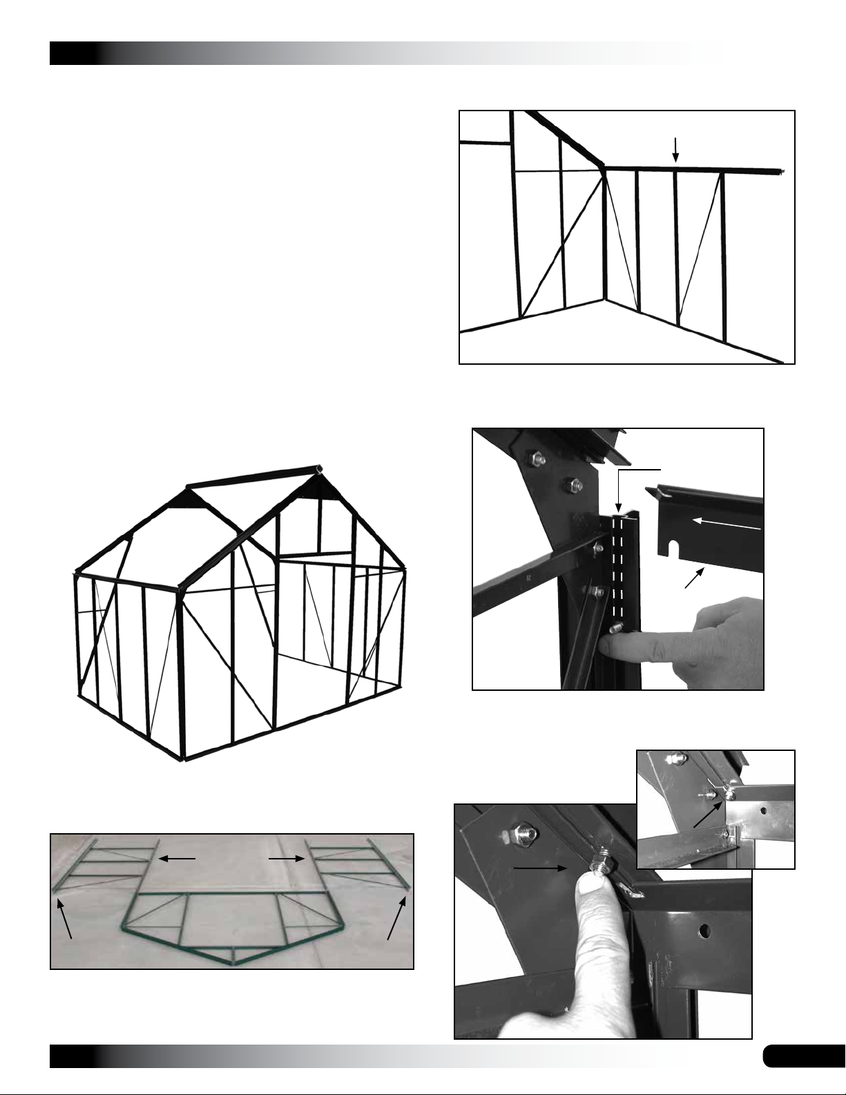
ASSEMBLE THE FIRST GREENHOUSE SECTION
The following steps describe how to connect the
greenhouse components you have assembled up to this
point. These steps are repeated as other greenhouse
sections are added.
ATTENTION: For best results, connect the assembled
greenhouse sections on a flat surface as shown.
Required parts to complete these steps:
• Assembled end wall (door end)
• Assembled sidewall frames (2)
• Assembled mid rafter (1)
GROWSPAN™ ESTATE ELITE GREENHOUSES
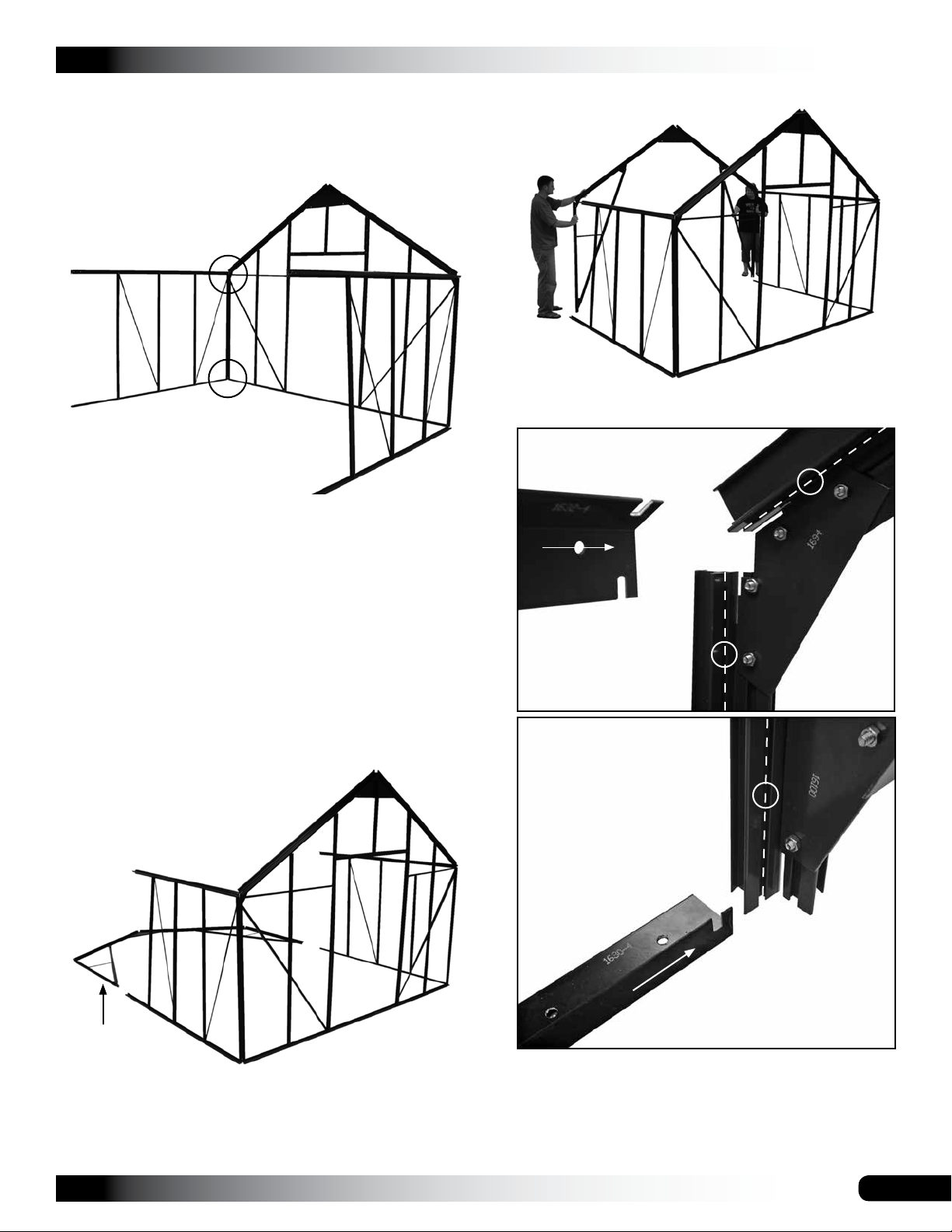
2. With assistance, lift the end wall and first sidewall
frame into position as shown.
Gutter Rail
• Ridge Beam (1650-4) from Box 7-2 (SKU: 104609) or
9-2 (SKU: 104611)
• Square-head bolts from Box 7-2 (SKU: 104609) or 9-2
(104611)
After the above sections are connected, the greenhouse
will appear as shown in this diagram:
Inside of the frame.
3. Slide a long bolt into the bolt track of the lower support
(1614) of the end wall. Use a piece of tape to keep it
from dropping to the bottom if desired.
Slide a long bolt
into the track.
Gutter Rail
Dashed line
shows bolt
track.
4. Slide a short bolt and nut into the bolt track of the upper
support, align the slot in the base rail with the bolt track
in the upper support, and tighten the upper bolt.
Complete the following steps.
1. Position the assembled frame sections as shown below
with the bolt tracks or inside surface facing up.
Base Rail
Gutter Rail
Gutter Rail
NOTE: Some frame photos may be of a different
model. The assembly process is the same.
Revision date: 01.01.16
17
GROWSPAN™ ESTATE ELITE GREENHOUSES
ASSEMBLE THE FIRST GREENHOUSE SECTION
(CONTINUED)
5. Detach the diagonal brace of the sidewall frame at the
base rail location (if needed) and slip the upper end of
the brace over the long bolt installed earlier in Step 3.
A. Detach brace from this
connection (if needed).
B. Slide long bolt
into position.
1632-4
NOTE: View below shows the corner connection from
the outside of the frame.
7. Move to the sidewall base rail, slide a bolt into the bolt
track of the 1614 lower support (if needed), and secure
the support to the base rail.
Sidewall
Base Rail
End Wall
Base Rail
1630-4
1610
Long
Bolt
C. Place upper
end of brace on
Brace
D. Slide the brace
and bolt up into the
slot of the gutter rail.
the long bolt and
add nut.
1632-4
Brace
6. With the upper end of the sidewall diagonal brace in
position, reattach the lower end to the base rail and
tighten both the upper and lower end bolts.
1630-4
View (right)
shows the
frame assembly
up to this point.
View shows
the backside or
inside surface.
End
Wall
1610
End Wall
Base Rail
Inside the Frame
View (left) shows
the same corner
from the outside.
Side Wall
18
Revision date: 01.01.16
ASSEMBLE THE FIRST GREENHOUSE SECTION
(CONTINUED)
8. Repeat the steps to secure the remaining sidewall
frame to the end wall frame.
Side Wall
View shows
the backside or
inside surface.
NOTE: Circles indicate where to secure the sidewall
frame to the end wall as describe earlier.
GROWSPAN™ ESTATE ELITE GREENHOUSES
2. With assistance, lift the mid rafter into position
3. Align the bolt tracks of the rafter with the slots in the
gutter rail of the sidewall frame as shown.
1632-4 Gutter Rail
9. Recheck all bolts to verify they are tight.
10. Brace the sidewalls so they stay in position and
continue by attaching the assembled mid rafter.
ATTACH THE ASSEMBLED MID RAFTER
After installing the first two sidewall frames, attach the
assembled mid rafter to the frame as described below.
1. Place the assembled mid rafter in line with the frame as
shown.
Slide bolt and nut
up into the bolt
track. See circles.
1630-4
Sidewall Base Rail
Assembled
Mid Rafter
ATTENTION: The bolt tracks of the lower 1614
supports must face up to attach the mid rafter to both
sidewall frames.
Revision date: 01.01.16
4. Slide a bolt and nut into the bolt track of the mid rafter.
See the circles above. Use tape or slightly tighten the
nut to keep the bolt from sliding out of the track.
19

GROWSPAN™ ESTATE ELITE GREENHOUSES
ATTACH THE ASSEMBLED MID RAFTER (CONTINUED)
5. Secure the rafter to the side wall using the bolts that
were installed earlier.
Mid Rafter
Slide bolt
Gutter Rail of the
sidewall frame.
and nut
up into the
gutter rail
slot.
7. Verify that all bolts are tight.
Mid Rafter
Slide bolt and
nut down into the
gutter rail slot.
NOTE: Dashed lines indicate the position of the gutter
rail, which is against the mid rafter bolt tracks.
Secure
sidewall base
rail to the mid
rafter.
Sidewall
Door End Wall
NOTE: The assembled frame up to this point is shown
above.
8. Continue with the installation of the first ridge beam
(1650-4).
INSTALL THE RIDGE BEAM
Depending on the length of the greenhouse the ridge beam
(1650-4) may be shipped in two or three identical sections.
For this procedure, only one section is installed. The
remaining section or sections are installed as the frame
assembly continues.
IMPORTANT: Consult the ridge beam note on the next
page for box location of the ridge beam.
The parts required for this procedure include:
6. Repeat the steps to attach the other mid rafter support
to the remaining sidewall frame.
20
Part Number Quantity
16506 (bracket) 2
Hex-Head Bolts 8
Square-Head Bolts (short) 4
Nuts for square-head bolts 4
NOTE: These parts are found in the following box for the
selected greenhouse:
Greenhouse Sku Number Work from this open box:
104609 C/No. 7-3
104611 C/No. 9-3
Continue with the procedure on the following page to install
the ridge beam (1650-4).
Revision date: 01.01.16

INSTALL THE RIDGE BEAM (CONTINUED)
Complete the following steps to install the ridge beam.
GROWSPAN™ ESTATE ELITE GREENHOUSES
Circles show where
to place the bolts.
RIDGE BEAM NOTE: Choose the 1650-4 ridge beam
from Box 7-2 for greenhouse 104609 and from Box 9-2 for
greenhouse 104611. (All ridge beams are identical.)
1. Remove the 1650-4 ridge beam from the correct box
and install the brackets (16506) as shown.
A. Collect the
parts.
Hex-Head Bolts
1650-4 Ridge
Beam
16506 Brackets
B. Insert the 16506
brackets into the
beam and thread the
hex-head mounting
bolts into the bracket.
See the insert below
for details.
View shows the assembly from
the inside.
NOTE: Bolts will slide to the bottom of the track. Use a
small piece of tape or slightly tighten the nuts to keep
the bolts near the peak.
3. With assistance, lift the ridge beam into place.
NOTE: Attach
the end, which
is without the
brackets, to the
end wall frame.
View shows the
end wall from the
outside.
End Wall
Frame
Brackets are used
to connect the ridge
beam to the next
ridge beam.
C. Slightly
tighten the
mounting bolts.
These may need
to be loosened
when the next
ridge beam is
added.
WEAR EYE PROTECTION
NOTE: Do not fully tighten the bolts at this time. Bolts
are tightened when the next ridge beam is installed.
2. Take two (2) square-head bolts with nuts and slide one
(1) into each bolt track of the upper supports as shown
in the next diagram.
4. With the ridge cap in place, tighten the bolts.
Diagrams above show the underside of the ridge beam.
The assembled frame to this point is shown in the
diagram below.
5. Assemble the next section of sidewall frame.
Revision date: 01.01.16
21

GROWSPAN™ ESTATE ELITE GREENHOUSES
1632-4
1630-4
ASSEMBLE NEXT 2 SECTIONS OF SIDEWALL FRAME
With the first section of greenhouse frame assembled,
construct the next two (2) side wall sections.
Dashed line above shows the next sidewall frame section
to be assembled. (The adjacent side is not outlined.) The
parts for this procedure are found in the box identified in the
table below for the selected greenhouse:
The circles show where to use the longer, square-head
bolts.
163116311631
1633 1633
This edge will
be attached to
the mid rafter of
the assembled
main frame.
Greenhouse Sku Number Work from this open box:
104609 C/No. 7-3
104611 C/No. 9-3
Consult the table below and the sidewall diagrams and
collect the parts needed to assemble the next two (2)
sidewall frame sections:
Part Number Quantity
1631 6
1632-4 2
1630-4 2
1633 4
Square-Head Bolts (short) See frame diagram.
Square-Head Bolts (long) See frame diagram.
Nuts for all bolts Same as bolt quantity.
Complete these steps to assemble the sidewall frame
sections:
1. Consult the diagram in the next column to arrange the
parts as shown.
ATTENTION: View of the sidewall is from the inside (or bolt
track side) for one side frame and from the outside for the
other side frame. When placed together with the bolt tracks
inward, the frames match and the diagonals will line up.
2. Refer to the previous sidewall frame instructions to
construct these two (2) sections of sidewall framing.
3. Place the assembled frames as shown in the diagram
to the right.
4. Continue by attaching these sidewall frames to the
assembled main frame.
22
NOTE: The end diagonal brace is not shown. It is installed
after the sidewall frames are attached to the main frame.
Revision date: 01.01.16

ATTACH THE SIDEWALL FRAMES TO MAIN FRAME
These sections of sidewall frames are attached to the main
frame using special brackets. Consult the following table to
select the parts to complete these steps.
Part Number Quantity
16306 2
16326 2
Phillips Pan-Head Screws 8
Hex-Head Bolts 16
Nuts for all bolts 16
The parts for this procedure are found in the box identified
in the table below for the selected greenhouse:
Greenhouse Sku Number Work from this open box:
104609 C/No. 7-3
104611 C/No. 9-3
Complete these steps:
1. Take the 16306 brackets and four (4) of the Phillips
screws and attach one (1) bracket to each base rail of
the assembled main frame.
GROWSPAN™ ESTATE ELITE GREENHOUSES
2. With assistance, set the sidewall frame in position.
3. Slide the sidewall frame onto the 16306 bracket
attached to the main frame and secure it in place using
the Phillips pan-head screws.
Slide notched
upper lip
behind the mid
rafter support
to connect the
sidewall base
rails.
ATTENTION: The holes in the 16306 bracket are threaded
to receive the Phillips pan-head screws.
16306
NOTE: These brackets are used to secure the separate
sidewall sections together.
Revision date: 01.01.16
NOTE: Verify that the joint between the two base rails
is tight. The notched upper lip of the base rail slides
behind the lower support of the mid rafter.
Tighten the Phillips screws
to secure the joint.
23

GROWSPAN™ ESTATE ELITE GREENHOUSES
ATTACH SIDEWALLS (CONTINUED)
4. Take two (2) 16326 brackets and eight (8) hex-head
bolts and nuts and secure the sidewall gutter rails as
described and as shown.
16326 Brackets
ATTENTION: The holes in the 16326 brackets are not threaded.
Use the hex-head bolts and nuts to secure the brackets.
Move to the inside of the frame and slide the 16326 bracket
between the gutter rail and mid rafter.
Verify that the gutter rails
are seated tightly.
Secure the bracket to the gutter rails using the hex-head bolts.
5. Repeat the steps to attach the remaining sidewall
frame to the main frame as previously described.
6. After attaching both sidewall frame sections, continue
with the procedure that follows on the next page for the
selected greenhouse.
For the 104609 greenhouse, continue with the steps
that follow the 104609 GREENHOUSE heading.
For the 104611 greenhouse, continue with the steps
that follow the 104611 GREENHOUSE heading.
Attach the 16326 bracket to the outside of the gutter rails.
Add the hex-head bolts and nuts and tighten. Install the
nuts on the outside as shown or on the inside if desired.
24
ATTENTION: TO AVOID TWISTING OFF OR DAMAGING
THE FASTENERS, DO NOT OVERTIGHTEN.
FOR YOUR CONVENIENCE, ADDITIONAL FASTENERS
CAN BE FOUND IN THE "EXTRA PARTS" BAG OR BOX.
REFER TO THE BILL OF MATERIALS FOR A LIST OF
THE FASTENERS CONTAINED IN THAT BAG OR BOX.
Revision date: 01.01.16

104609 GREENHOUSE
GROWSPAN™ ESTATE ELITE GREENHOUSES
104611 GREENHOUSE
After installing the last two (2) sections of sidewall framing,
take the assembled end wall frame (no door) and attach it
to the end of the main frame. Complete these steps:
1. Consult the previous "Assemble the First
Greenhouse Section" procedure if needed to view
the details for attaching a sidewall frame to an end wall
frame.
End Wall (no door)
After installing the two (2) sections of sidewall framing,
complete or repeat the following procedures.
ATTENTION: This procedure requires parts from Box 9-8
for the 104611 greenhouse.
1. Take the 1650-4 ridge beam from Box 9-3, close the
box, and set the ridge beam on the box for later use.
2. Open Box 9-8. Do not mix the parts from separate
boxes.
3. Using the previous "Assemble Main Frame Mid
Rafter" procedure, select the required parts, and
assemble the final mid rafter.
4. Attach the mid rafter to the main frame as described in
the "Attach the Assembled Mid Rafter" procedure.
2. After attaching the sidewall frames to the final end wall
frame, install the final section of 1650-4 ridge beam.
The beam is found in Box 7-3 for 104609. Use the
previous "Install Ridge Beam" instructions to set the
final ridge beam (1650-4) on the frame and to attach it
to the installed ridge beam and to the frame. Consult
the diagrams below for details.
NOTE: Diagram may shown
a ridge beam that differs in
design from actual beam.
Brackets are the same
however.
Ridge Beam
104611 Frame
5. Take the 1650-4 ridge beam (Step 1 above) and refer
to the "Install Ridge Beam" procedure to attach the
16506 brackets to the beam and to attach the beam to
the installed ridge beam and to the main frame.
3. With the end wall and ridge beam in place, continue
by installing the roof rafters as described in the ROOF
FRAME INSTALLATION procedure.
Revision date: 01.01.16
104611 Frame
NOTE: The 16506 brackets and hex-head bolts for
this step are found in Box 9-8. Refer to the diagram
(Step 2) in the left column to attach the separate ridge
beams.
25

GROWSPAN™ ESTATE ELITE GREENHOUSES
104611 ASSEMBLY (CONTINUED)
6. Using the previous "Assemble Next 2 Sections of
Sidewall Frame" instructions, construct another pair of
sidewall frames with parts from Box 9-8.
7. Attach the assembled sidewall frames to the main
frame. Use the "Attach Sidewall Frames to Main
Frame" procedure.
8. Once the final sections of sidewall frames are attached
to the assembled main frame, attach the final end wall
frame to the main frame.
End Wall (no door)
ROOF FRAME INSTALLATION
The roof rafters are installed with the bolt tracks to the
inside of the greenhouse.
ATTENTION: Consult the Roof Frame diagrams near the
end of this instruction packet for a quick overview of the
roof frame assembly for your greenhouse.
1. Select the first set of rafters (1651), diagonal braces
(1695), and bolts and nuts from the following box:
Greenhouse Sku Number Work from this open box:
104609 C/No. 7-2
104611 C/No. 9-2
2. Consult the Roof Frame diagram near the back of
these instructions to determine the position of the parts
and where to install additional bolts.
3. Working from the door end of the frame, move to the
first rafter position on one side of the roof, slide the
required number of bolts into the bolt track of the 1651
rafter, and attach the rafter to the gutter rail and to the
ridge beam.
Next set of sidewalls.
NOTE: Consult the previous "Assemble the First
Greenhouse Section" procedure if needed to view
the details for attaching a sidewall frame to an end wall
frame.
9. Attach the final section of 1650-4 ridge beam (from Box
9-8) to the previous ridge beam and to the frame.
Final Ridge Beam
10. With the final ridge beam secured to the main frame,
continue with the ROOF FRAME INSTALLATION
procedure.
Rafter (1651)
Gutter Rail
1632-4
Vertical Support
Sidewall (1631)
View is from the inside of the greenhouse.
NOTE: Verify that the correct number of additional bolts
for vents and diagonal struts has been slid into the bolt
track of each 1651 rafter that is installed. Consult the
Roof Frame diagram for details.
Ridge
Beam
26
NOTE: Ridge beam
may differ in design from
actual beam.
Extra Bolt
Revision date: 01.01.16

ROOF FRAME INSTALLATION (CONTINUED)
4. Tighten the mounting bolts at the gutter rail and ridge
beam positions at this time.
NOTE: The additional bolts slid into the track for each
rafter are used when the diagonal braces and vents are
installed.
5. Repeat these steps to install the remaining 1651 rafters
from the box identified in Step 1.
6. Follow the Roof Frame diagram near the back of this
document to determine the position of each diagonal
brace and install the braces (1695).
See insert
below.
GROWSPAN™ ESTATE ELITE GREENHOUSES
8. Add a nut to the bolt. Once the diagonal is secured to
each rafter, tighten the nuts.
9. After all rafters and diagonals are installed from the
first box (Step 1), move to the next box (shown below),
and repeat the steps to install the rafters (1651) and
diagonal braces (1695) from that box.
Greenhouse Sku Number Work from this open box:
104609 C/No. 7-3
104611 C/No. 9-3
NOTE: As rafters are added, continue working from
the door end toward the non-door end wall of the
assembled frame.
10. After all rafters and diagonals are installed from the
second box (Step 9), complete the following step for
the selected greenhouse:
For the 104609 greenhouse, continue with the "Roof
Vent Assembly and Installation" instructions.
View shows the end wall peak and
ridge beam from the inside. Frame
design may differ from actual frame.
ATTENTION: The nuts used to secure the ridge beam
and gutter rail are removed and reattached to secure
the ends of each diagonal brace at those locations
shown on the Roof Frame diagram.
7. Where a diagonal brace crosses a rafter, slide one (1)
of the extra bolts on the rafter to the diagonal and place
it in the pre-drilled hole on the diagonal.
View above shows the
brace as attached to the
underside of the roof
rafters.
104609 Frame
For the 104611 greenhouse, continue with the next
step.
11. Remove the 1651 rafters and the 1695 braces from
Box 9-8 (104611 only) and repeat the steps to attach
these to the assembled frame.
104611 Frame
12. After installing all rafters and diagonal braces, continue
with the "Roof Vent Assembly and Installation"
instructions.
Revision date: 01.01.16
27

GROWSPAN™ ESTATE ELITE GREENHOUSES
ROOF VENT ASSEMBLY AND INSTALLATION
All vent frame parts are packaged in two (2) separate poly
bags for each roof section. Consult the table below for box
numbers for your greenhouse:
Greenhouse Sku Number Vent frames in boxes:
104609 C/No. 7-2 and 7-3
104611 C/No. 9-2, 9-3, and 9-8
NOTE: All photos show the vent frame with the inside
surface facing up. When installed, the frame surface shown
in the photos is seen from inside the greenhouse.
All vent frames are identical and assembled the same.
1. Locate and open one (1) vent frame package.
NOTE: To avoid mixing parts, open one frame only.
2. Arrange the parts as shown. See the Vent Frame
diagram for part identification if needed and complete
the assembly.
6. Remove the bolt from the pre-assembled vent support
arm (1674) and attach the mounting bracket to the
frame (1672) and reattach the 1674 support arm.
Channel is visible
when arm is
installed correctly.
3. Using the small Phillips head bolts and nuts, attach the
bottom rail to the side rails. Do not tighten these at this
time.
4. Next, attach the top hinge rail to the side rails using the
Phillips head bolts.
5. Using a carpenter's square (or other means), verify that
the assembled vent frame is square and tighten the
bolts.
NOTE: Attach the mounting bracket to the frame using
a small bolt and a self-locking nut. The bracket and arm
must be allowed to swivel on the frame rail. When the
arm is properly installed, the channel of the support
arm will be visible from inside the greenhouse when the
arm is properly installed.
7. Repeat the above steps for the remaining support arm.
8. Once the vent frame is assembled, locate the two 1675
cross members for the vent frame.
1675
Photo shows the notched edge of the 1675 cross
member, which is installed toward the ridge beam (or
peak) of the greenhouse roof. The selected hole in the
channel of the 1674 support arm is placed over the
center pin of the notch to hold the vent open.
28
Revision date: 01.01.16

ASSEMBLE AND INSTALL THE ROOF VENTS
(CONTINUED)
9. Install the two (2) 1675 cross members between the
three rafters where the vent frame will be installed.
1675
1651
1632-4
1631
GROWSPAN™ ESTATE ELITE GREENHOUSES
Photo below shows one end of the 1675 cross member
where it is attached to the rafter. The bolt is on the
underside of the rafter (which is to the inside of the
greenhouse).
To the ridge
beam
1651
1675
NOTE: View shows the frame as seen when standing
on the inside. Only one (1) 1675 frame member is
shown in the above photo.
10. Using the bolts added to the bolt tracks of the rafters,
attach the cross members (dashed line below) between
the three (3) rafters. Bolts should remain snug. Do not
fully tighten the bolts at this time.
1675
Additional
bolt to
attach
the 6577
bracket to
the rafter.
NOTE: Picture shows where to position the 1675 cross
member. The frame shown may differ from the actual
greenhouse. Consult the diagrams near the back of
these instructions for additional details.
The last additional bolt in the track of the second and
third rafter must remain between the bolt used to
secure the 1675 cross member and the bolt used to
secure the 1651 rafter to the 1632-4 gutter rail.
See the circles in the above photo. These bolts are
used to attach the 6577 brackets to the rafters. The
6577 brackets secures the vent support arm when the
vent is closed. Add bolts if needed.
View shows the 1675 cross member from the outside.
11. After attaching the 1675 cross members, take the
assembled vent frame and insert one end of the 1670
frame member into the C-channel of the ridge beam.
See the photos below and vent frame diagram near the
back these instructions for details.
ATTENTION:
Ridge beam design
may differ from
actual beam. Vent
installation is the
same.
1670
Ridge Beam
Top Hinge Rail
of Vent Frame
Slide the 1670 frame member into the channel of the
ridge beam. The side of the vent frame that was facing
up during its assembly should now be facing to the
inside of the greenhouse frame.
Ridge Beam
Top of
Hinge Rail
ATTENTION: You must flip the assembled vent frame
over so that the rounded edge of the top hinge rail can
be inserted into the channel of the ridge beam.
Revision date: 01.01.16
29

GROWSPAN™ ESTATE ELITE GREENHOUSES
ASSEMBLE AND INSTALL THE ROOF VENTS
(CONTINUED)
12. Continue to slide the vent frame into the channel until
the vent frame is aligned between the two rafters where
the 1675 cross members were installed.
13. Once aligned, allow the vent frame to rest in the closed
position on the rafters.
14. Loosen the bolts (if needed) and slide the 1675 cross
members up until it touches the bottom rail of the
assembled vent frame. See the photo below.
Ridge Beam
Bottom Rail of Vent Bottom Rail of Vent
Rafter
16. Working from inside the greenhouse, close the vent
and swivel the vent support arm down and toward the
second rafter.
1674 Support
Arm
1675
View is from the outside of the greenhouse. The double
vents will span two (2) rafter sections.
NOTE: To prevent binding, do not seat the 1675 cross
members tightly against the bottom rail of the vent
frame.
Bottom Rail
of Vent
Bottom Rail
of Vent
1674
1675
1674
Ridge
Beam
Rafter
View is from the inside of the greenhouse looking up at
the installed vent frame and the 1675 cross members.
15. With the cross member in position, test the operation of
the vent frame and tighten the bolts to secure the 1675
cross members.
NOTE: This will be the rafter where the remaining
"extra" bolt is located. If no bolt is present, loosen the
rafter at the gutter rail, slide a bolt into the bolt track,
and retighten the rafter mounting bolt.
17. Slide the remaining bolt up to the support arm as
shown and attach the Z-bracket as shown below.
6577 Bracket
18. With the 6577 bracket attached, lift the support arm
out of the bracket and remove the vent frame from the
greenhouse to install the polycarbonate panel.
NOTE: The polycarbonate panels for the vents can
be installed with the vent frame attached to the
greenhouse roof if desired. This procedure installs the
polycarbonate panels with the assembled roof vents
removed for easier accessibility.
19. Repeat the steps to assemble and install the remaining
vent frame or frames.
30
20. After all vents are assembled, installed, fitted in the
frame, and removed, install the vent panels.
Revision date: 01.01.16

INSTALL THE POLYCARBONATE VENT PANELS
The steps below describe attaching the polycarbonate
vent panels to the assembled vent frames. The panels are
lettered for identification. Consult the panel diagrams and
the diagrams on the outside of each shipped box to locate
and identify parts. See Page 40 for additional information.
The parts needed to complete the vent frame assembly
include the following:
GROWSPAN™ ESTATE ELITE GREENHOUSES
3. Take one U-strip and install it on the top edge of the
polycarbonate panel.
Plastic U-Strip
• Polycarbonate Panels: Letter X
• U602 U-profile and silicone
Greenhouse Sku Number Panels/U602 in boxes:
104609 C/No. 7-6 and 7-7
104611 C/No. 9-6, 9-7, and 9-9
NOTE: The plastic U-strips are precut and are as long as
the polycarbonate panel is wide. You do not have to cut any
plastic molding. If it appears as though the plastic profile
is the incorrect length, verify that you have selected the
correct panel and profile. Consult the panel diagrams near
the back of these instructions for details.
Do not allow panels to remain in direct sunlight with the
protective film intact.
Complete these steps:
ATTENTION: Install the polycarbonate panels with the
UV-protected side to the outside of the greenhouse. If you
remove the protective film before installing the panels, mark
the panel in a lower corner to identify the UV-protected
side.
1. Locate the first X panel and the plastic U-strips for that
panel.
Install this
Install this
edge on the
backside of
the panel.
edge toward
the UVprotected side
of the panel.
Polycarbonate Panel
NOTE: The top and bottom edges of each panel show
the hollow cells inside the panel. When installing the
plastic molding, rest the panel on cardboard or other
material to protect the edges and surface of the panel.
4. Take the remaining strip and attach it to the bottom
edge of the panel.
X
Photo shows one panel to cover one side of the vent
frame.
5. With both U-strips installed on the panel, remove the
remainder of the protective film.
Plastic U-Profile
2. Carefully peal the protective film away from the edge
on both sides of the panel if needed.
To prevent scratching the panel, do not completely
remove the protective film until the plastic U-strips are
installed.
Revision date: 01.01.16
6. Mark the UV-protected side with a piece of tape or a
marker and set the panel to the side.
31

GROWSPAN™ ESTATE ELITE GREENHOUSES
INSTALL THE POLYCARBONATE VENT PANELS
(CONTINUED)
7. Move to the assembled vent frame, open a tube of
silicone, and apply a small bead along the sides of the
vent frame on the outside surface.
Top
ANCHORING INSTRUCTIONS
To prevent serious personal injury and property damage,
you must anchor the assembled greenhouse frame before
continuing.
Failing to properly anchor the greenhouse frame will void all
warranties.
If you did not purchase one of our recommended anchoring
systems and want to now, contact your sales representative
at 1-800-245-9881.
Consult a professional and qualified contractor for
anchoring suggestions if you have not decided how to
anchor the greenhouse.
Read the anchoring information that follows and anchor the
assembled greenhouse frame.
ANCHOR THE GREENHOUSE
Smaller vent shown for clarity.
ATTENTION: The vent frame is positioned with the
outside facing up. The dashed line shows where to
apply the silicone.
8. With the silicone applied, take the prepared panel
and set it in the vent frame with the UV-protected side
facing up to the outside.
Photo shows the polycarbonate panel as installed in
the vent frame. (In the photo, the protective film was
not removed to better show the panel in the frame.)
The site and whether the optional base is used determine
the recommended anchoring methods for the greenhouse.
WARNING: You must anchor the greenhouse (and
the base if used) to the site and before installing the
panels. Failing to do so may result in property damage
and personal injury.
The information below identifies the recommended
anchoring methods for your greenhouse. There are four
basic scenarios when anchoring the greenhouse. Choose
the one that matches your particular application.
If none of the following anchoring suggestions is
applicable to your greenhouse, you must seek the advice
of a professional and qualified contractor to anchor your
greenhouse to the site.
ATTENTION: Since different applications require different
anchoring methods, contact your sales representative for
the parts required to anchor the greenhouse and frame.
Contact Customer Service at 1-800-245-9881 to purchase
additional anchoring parts.
Continue with the following anchoring information on the
following page.
9. Repeat the above steps for all remaining vent panels.
10. After the silicone sets, slide the vent frames back into
to the ridge beam (if they were removed to install the
polycarbonate panels).
11. Read the anchoring instructions and information that
follows and then continue with the door assembly
procedures after you anchor the greenhouse frame.
32
ATTENTION: TO AVOID TWISTING OFF OR DAMAGING
THE FASTENERS, DO NOT OVERTIGHTEN.
FOR YOUR CONVENIENCE, ADDITIONAL FASTENERS
CAN BE FOUND IN THE "EXTRA PARTS" BAG OR BOX.
REFER TO THE BILL OF MATERIALS FOR A LIST OF
THE FASTENERS CONTAINED IN THAT BAG OR BOX.
Revision date: 01.01.16

ANCHOR THE GREENHOUSE (CONTINUED)
SCENARIO #1: Base Frame On Soil (or Gravel) Site
Ground posts are used to anchor the optional base to the
site before the assembled greenhouse frame is set on the
base.
1. After squaring the base and driving the support posts
into the ground (see the Base Assembly instructions
presented earlier in this packet), select the ground
posts for the anchoring system.
2. Determine whether you want the ground posts on the
inside or outside of the base assembly.
NOTE: Ground posts are driven into the site near each
corner of the assembled frame. Ground posts must be
ordered. They are not included with the greenhouse.
3. Using the following diagrams, drive each ground post
into the site flush with the top of the base channel.
GROUND POST OUTSIDE
BASE FRAME
GROWSPAN™ ESTATE ELITE GREENHOUSES
4. With the ground posts driven into place, use the holes
in the ground post as a guide, drill a hole through the
base channel, and attach the base to each ground post
as shown in the previous diagrams.
5. With the base secured, set the assembled greenhouse
frame on the anchored base.
6. Attach the greenhouse frame to the anchored base
using self-tapping screws driven through the base rail
and into the base channel.
Greenhouse
Base Rail
Carriage Bolt
Base Channel (additional purchase)
Ground Post
Diagram shows ground post driven to the
top of the base channel on the outside of the
base frame.
NOTE: When the ground post is on the inside of the
base, use as spacer placed between the base channel
and ground post to prevent crushing the channel when
the bolts are tightened as shown below.
GROUND POST INSIDE
BASE FRAME
Spacer
placed
between
channel and
ground post
Carriage Bolt
Photo is used for illustration purposes only. The dashed
line shows the lip of the base rail of the greenhouse.
NOTE: Count the Tek screws sent with the base kit and
install screws evenly around the perimeter of the frame
between each vertical support.
7. Continue with the greenhouse assembly procedures as
instructed.
EXTRA PARTS PROVIDED FOR GREENHOUSE
ATTENTION: TO AVOID TWISTING OFF OR DAMAGING
THE FASTENERS, DO NOT OVERTIGHTEN.
FOR YOUR CONVENIENCE, ADDITIONAL FASTENERS
AND PLASTIC MOLDING CAN BE FOUND IN THE
"EXTRA PARTS" BAG OR BOX.
REFER TO THE BILL OF MATERIALS FOR A LIST OF
THE FASTENERS AND MOLDING CONTAINED IN THAT
BAG OR BOX.
Base Channel
Revision date: 01.01.16
Ground Post
The plastic profile can be trimmed to the required length if
a piece is misplaced or damaged during installation.
IMPORTANT: Consult the "extra parts" for items you
need before contacting customer service to request a
replacement for damaged or missing parts or fasteners.
33

GROWSPAN™ ESTATE ELITE GREENHOUSES
ANCHOR THE GREENHOUSE (CONTINUED)
SCENARIO #2: Base Frame On Concrete (Slab or
Patio)
Concrete anchor bolts are used to secure the base to the
concrete slab before the assembled greenhouse frame is
set on the base.
1. After the base is assembled and the frame support
posts are cut to the proper length (see the Base Frame
Assembly instructions) position the base on the site
with the bottom edge of the base facing up.
2. Using a drill bit the same diameter as the concrete
anchor bolts, drill holes through the edge of the base
channel.
NOTE: Use 24" spacing when drilling the holes. You
must use concrete wedge anchors for this application.
Photo shows holes for the anchor bolts as
drilled in the bottom of the base frame.
SCENARIO #3: No Base Frame: Greenhouse Is On
Concrete Slab (or Patio)
If the greenhouse frame is assembled and no base frame
is used, the greenhouse is anchored to the concrete using
anchor bolts as previously described.
1. Position the assembled greenhouse on the site and
square the greenhouse using the technique described
in the Base Assembly instructions presented earlier in
this packet.
2. After squaring the assembled greenhouse frame,
drill a hole through the base rail of the sidewall of the
greenhouse frame and install a concrete anchor bolt.
Drill holes in the center
of the base rail.
3. After all holes are drilled, flip the base frame and
reposition it on the site.
4. Square the frame as previously described in the Base
Assembly procedure.
5. Using the holes drilled in the base channel (Step 2) as
guides, take a marker, and mark the hole location on
the concrete.
6. Remove the frame, drill the holes in the concrete
using the proper bit, and install the anchor bolts in the
concrete.
7. Reposition the base frame over the anchor bolts in
the concrete and anchor the base to the site using the
anchor bolts.
8. Anchor the assembled greenhouse frame to the
base as shown in Step 6 of the previous anchoring
instructions and continue with the greenhouse
assembly procedures as instructed.
NOTE: Holes for the anchor bolts are drilled through
the base rail and into the concrete between each of the
vertical supports. Photo above shows the greenhouse
frame as seen from the outside of the greenhouse.
3. Move to the opposite side of the frame and repeat the
previous step to anchor the frame to the site.
4. Continue by repeating the above steps until the
greenhouse frame is anchored.
5. After anchoring the greenhouse frame, continue with
the greenhouse assembly instructions.
34
Revision date: 01.01.16

SCENARIO #4: No Base Frame: Greenhouse Is On
Soil (or Gravel)
To anchor the assembled greenhouse frame to a nonconcrete site without the optional base frame, you must use
a treated-wood base frame to set the greenhouse on.
Ground posts are then driven into the ground on either the
inside or outside of the treated-wood base frame. The wood
frame is anchored to the ground posts using lag screws
inserted through the ground post holes and screwed into
the wood.
After securing the treated-wood frame to the ground posts,
the assembled greenhouse frame is placed on the wood
base, squared, and anchored to the wood base using lag
screws inserted through pre-drilled holes in the base rail
of the greenhouse frame and screwed into the wood. Use
the diagrams below to anchor the greenhouse to a nonconcrete site when the optional base frame is not used.
Diagram shows lag screws installed through the ground
post and into the 4" x 4" treated wood base frame. The
dashed line shows where to install the lag screw when a
2" x 4" or 2" x 6" treated-wood frame is used.
GROWSPAN™ ESTATE ELITE GREENHOUSES
ASSEMBLE AND INSTALL THE DOORS
After anchoring the greenhouse frame, assemble the door.
NOTE: The following photos may show a door of a different
color or slightly different design. The assembly and
installation procedures are the same for all similar doors
and applications. Consult the door diagram near the back
of these instructions for part details.
Greenhouse Sku Number Door frames in box:
104609 C/No. 7-4
104611 C/No. 9-4
Complete these steps to assemble and attach the door to
the greenhouse frame.
1. Locate all door parts and assemble them on a clean
surface. (Place and assemble the parts on cardboard
to protect the finish.)
Lag Screw
Ground Post
Greenhouse
Frame
Install lag screw through
pre-drilled hole in greenhouse
frame and into the treatedwood base.
Diagram may not be to scale.
NOTE: Only the top hole in the ground post is used when a
2" x 4" or 2" x 6" treated-wood base is used.
In all instances for the wood base, the ground posts are
driven flush to the top of the wood base as shown.
After anchoring the treated-wood frame to the site and the
greenhouse frame to the wood frame, continue with the
greenhouse assembly instructions that follow.
Revision date: 01.01.16
See the Door Frame Diagram for parts identification.
35

GROWSPAN™ ESTATE ELITE GREENHOUSES
ASSEMBLE AND INSTALL THE DOORS (CONTINUED)
2. Slide the bolts into the bolt track of the door cross
members and attach the cross members to the vertical
side members of each door frame.
Bolts
NOTE: Verify that the side members are seated tightly
to the cross member to maintain door width.
View shows the outside surface.
The dashed line (below) shows the location of the
16640 frame member shown in the photo below.
5. Secure the assembled door frame to the greenhouse
end wall frame.
This procedure
describes attaching
the assembled
doors to the end
wall framing and
then installing the
polycarbonate
panels for the door.
If you want to install
the panels before
the doors are hung,
skip to that section
and install the
panels. Then return
to this step to attach
the doors to the end
wall frame.
Secure
hinges to
end wall
frame.
3. Continue connecting the door components until all door
frames are assembled.
4. Locate the door stop frame member (16640) and attach
it to the inside top of the lower door frame. (Screws to
mount this are usually included inside the plastic that
the door stop is packaged in.)
16640
NOTE: When attached correctly, the 16640 door
stop prevents the upper door from swinging into the
greenhouse.
36
ATTENTION: Loosen the header of the end wall and
move it up if the opening is too small for the door.
End Wall Frame
To adjust the header, loosen the bolts only in the
locations identified by the circles in the above diagram.
Revision date: 01.01.16

ASSEMBLE AND INSTALL THE DOORS (CONTINUED)
6. Attach the latch to the inside of the upper door as
shown below. Some latches come pre-installed.
GROWSPAN™ ESTATE ELITE GREENHOUSES
NOTE: Verify that you have selected the correct panels and
U-profile. You do not have to cut any plastic profile. Consult
the panel diagrams near the back of these instructions for
additional information.
16640 Door
Stop
Latch
Assembly
NOTE: If your greenhouse includes a single door,
assemble and attach that door frame now and continue
with the next steps.
7. Once the doors are assembled and installed, return
to the header of the end wall frame and adjust it as
needed. See diagram in Step 5 if needed.
NOTE: After adjusting the header, test the operation of
the doors to verify that enough clearance is present to
allow the doors to open an close smoothly.
Complete these steps:
ATTENTION: Install the polycarbonate panels with the
UV-protected side to the outside of the greenhouse. If you
remove the protective film before installing the panels, mark
the panel in a lower corner to identify the UV-protected
surface. See page 40 for additional polycarbonate
installation information.
1. Locate the first Y panel and two lengths of the U485
profile for that panel.
2. Carefully peal the protective film away from the edge
on both sides of the panel.
NOTE: To protect the panel, do not completely remove
the protective film until the U-profile strips are installed.
3. Take one U485 profile section and install it on the top
edge of the polycarbonate panel.
Install this
Install this
edge on the
backside of
the panel.
edge toward
the UVprotected side
of the panel.
8. Tighten all header bolts and test the operation of all
latches. Adjust header if needed and retighten.
9. Prepare and install the polycarbonate door panels.
INSTALL THE POLYCARBONATE DOOR PANELS
The steps to prepare and install the polycarbonate panels
for the doors are similar to those described in the vent
panel installation procedure. The door panels are lettered
for identification.
NOTE: The protective film has not been removed in the
following photos. You must remove the film as instructed
during the assembly process.
The parts needed to complete the door frame assembly
include:
• Polycarbonate Panels: Y
• U485 U-profile and silicone
Greenhouse Sku Number Panels/U485 in box:
104609 C/No. 7-5
104611 C/No. 9-5
Plastic U-Profile
NOTE: The top and bottom edges of each panel show
the hollow cells inside the panel. When installing the
plastic profile, rest the panel on cardboard or other
material to protect the edges and surface of the panel.
U485 Profile
Polycarbonate Panel
4. Take the remaining U-strip and attach it to the bottom
edge of the panel.
Revision date: 01.01.16
37

GROWSPAN™ ESTATE ELITE GREENHOUSES
INSTALL THE POLYCARBONATE DOOR PANELS
(CONTINUED)
5. With the U-profile installed on the panel, remove the
protective film (if this has not been completed).
6. Mark the UV-protected side with a piece of tape or a
marker and remember that it is installed to the outside.
INSTALL THE GUTTER RAIL ENDS
Before installing the remaining polycarbonate panels, install
the plastic gutter rail ends as shown below.
Required parts include:
• 65841 (left hand fixture)
• 65842 (right hand fixture)
Greenhouse Sku Number Work from this box:
104609 C/No. 7-5
104611 C/No. 9-5
1. Locate the fixtures identified above and install these as
shown below for one side of the assembled frame.
1615
1632-4
7. Close the doors to prevent them from moving and
apply a bead of silicone along the panel frame edge of
the door. See the photo below.
NOTE: Photo shows the lower-right corner of one door
frame. Dashed line shows where to apply silicone.
8. Verify that the UV-protected surface is to the outside
and place a prepared panel into the door opening.
65841
1632-4
2. Repeat the steps for the remaining ends of the gutter
rails.
3. Continue by installing the cresting for the frame.
Cresting
9. Repeat the steps to attach the remaining polycarbonate
panels to the remaining door frames.
10. After the silicone sets to secure the panels, attach the
doors to the end wall frame (if needed) and continue
with the installation of the gutter ends.
38
Revision date: 01.01.16

INSTALL THE GREENHOUSE CRESTING
The cresting runs the length of the greenhouse and is slid
into the channel of the ridge beam (1650-4). Use the table
below to locate the required parts.
Greenhouse Sku Number For cresting, use box:
104609 C/No. 7-4
104611 C/No. 9-4
Locate and use these parts: pre-assembled cresting mid
sections and cresting end sections.
GROWSPAN™ ESTATE ELITE GREENHOUSES
3. Take each end section of cresting and slide one into
the ridge beam at each end to complete the installation.
Cresting End Section Cresting End Section
4. Continue with the installation of the ridge beam end
covers.
Cresting
16H58
Cresting Mid Section Cresting End Section
16H58
NOTE: As shown, the decorative cresting sections (8.3H55
and 16H56 listed on the Bill of Materials) come preassembled on the 16H58 sections of aluminum profile.
16H56
8.3H55
16H58
Complete these steps to install the cresting:
1. Locate one (1) assembled mid section and slide it into
the channel of the ridge beam (1650-4).
NOTE: Do not allow the individual cresting sections to
slide from the 16H58 channel.
2. Continue adding mid sections of the double cresting
until all sections have been slid into the ridge beam.
Assembled Mid Cresting
Ridge Beam (1650-4)
Sample frame above shows the installed cresting for the frame.
Frame shown differs from actual frame.
INSTALL THE RIDGE BEAM END COVERS
The end covers are used to close the opening at each end
of the ridge beam that runs the length of the greenhouse at
the peak of the greenhouse frame.
Consult the following table to locate the required end
covers and mounting screws:
Greenhouse Sku Number For end cover, use box:
104609 C/No. 7-2
104611 C/No. 9-2
Complete these steps:
1. Locate the end covers (1659) and the mounting
screws.
2. Using the proper lift or ladder to reach the ridge beam,
attach the end covers to the ends of the ridge beam.
Cresting
1659
Ridge Beam (1650-4)
NOTE: End covers and
mounting screws are
packaged together.
NOTE: For easier installation, slide the sections into
the ridge beam channel from both ends.
Revision date: 01.01.16
3. Continue with the installation of the polycarbonate
panels.
39

GROWSPAN™ ESTATE ELITE GREENHOUSES
INSTALL THE POLYCARBONATE PANELS
INSTALL THE FIRST SECTION OF PANELS
The remaining panels are installed based on the diagram
found on the outside of each shipped box. For best results,
follow these basic instructions to install the final panels:
1. Consult the panel installation and U-profile diagrams
at the back of these instructions and on the boxes that
contain the polycarbonate panels.
2. Work from one box only until all panels and U-profile
are installed from that box.
3. Do not cut any U-profile or panels!
4. Do not allow panels to remain in direct sunlight until all
protective film is removed and the panels are installed.
5. Wipe all frame surfaces with alcohol or other residuefree solvent in locations where silicone will be applied.
NOTE: Use solvents or alcohol as directed by those
manufacturers. Ensure adequate ventilation.
6. Always rest panels on a clean surface when installing.
Do not allow the panels to rest on the ground.
7. Install the UV-protected side to the outside (or toward
the sun).
8. Do not install during windy or wet conditions. The
installed panels must be protected from the elements to
allow the silicone to set.
Use the following information when installing the first set
of panels to cover the sides and roof of the greenhouse
frame:
Greenhouse Sku Number For wire clips, use box:
104609 C/No. 7-2
104611 C/No. 9-2
Greenhouse Sku Number For panels, use box:
104609 C/No. 7-6
104611 C/No. 9-6
You do not need to cut any plastic molding. To prevent
damage or injury, DO NOT install panels on a windy or
stormy day.
ATTENTION: Install the polycarbonate panel with the
UV-protected side to the outside of the greenhouse. If you
remove the protective film before installing the panel, mark
the panel in a lower corner so that the panel is installed
correctly.
1. Locate the first sidewall panel from the box identified in
the table and the U-profile for that panel and prepare
the panel as previously described.
2. Carefully peal the protective film away from the edge
on both sides of the panel.
9. If desired, seal the open cells at the top edge of each
panel with tape or with silicone before installing the U-
profile to prevent dirt from entering the cells.
NOTE: Do not seal the bottom of any panel with
silicone. These cells must remain open and free of
debris to allow condensation to drain from the panel
cells. (See Item 10 for optional vent tape purchase.)
10. Vent tape (additional purchase required): If vent tape
was purchased, apply this tape at the bottom of each
polycarbonate panel before installing the U-profile. Vent
tape is not required but helps keep dirt from inside the
cells and allows condensation to drain from the cells.
11. Purchase additional silicone if needed. The size of the
bead of silicone used determines the amount of silicone
required to secure and seal the remaining panels.
It may be necessary to purchase additional silicone
locally to complete the panel installation.
NOTE: An 1/8" bead is typically sufficient to seal and
secure a panel to the greenhouse frame.
12. Consult the previous panel installation steps to review
the basic installation steps.
13. Start the remaining panel installation at the door end of
the frame. Use the diagrams attached to each shipped
box as guides when installing the panels.
Install this
Install this
edge on the
backside of
the panel.
Plastic U-Profile
edge toward
the UVprotected side
of the panel.
Do not completely remove the protective film until the
plastic U-strips are installed.
3. Take one section of U-profile and install it on the top
edge of the polycarbonate panel. If desired, you can
seal the top edge of the panel before the U-profile is
installed. (See the next photo.)
NOTE: The top and bottom edges of the panel show
the hollow cells inside the panel. When installing the
plastic molding, rest the panel on cardboard or other
material to protect the edges and surface of the panel.
40
Revision date: 01.01.16

INSTALL FIRST SECTION OF PANELS (CONTINUED)
4. Take another section of U-profile and attach it to the
bottom edge of the panel.
U-Profile
GROWSPAN™ ESTATE ELITE GREENHOUSES
8. Move to the frame and, standing outside the frame,
apply a bead of silicone in the channel of each frame
member in the areas shown below by the dashed lines.
Dashed line
shows where to
apply silicone
before installing
1631
the panel.
Polycarbonate Panel
Photo is used to illustrate the location of the U-profile.
The panel size may differ from the actual panel.
U-Profile
5. Move to the frame where the panel will be installed and
clean the surfaces where the silicone will be applied.
NOTE: The surface for the silicone on the frame must
be free of oil and dirt for best results. See the profile
and panel diagrams and photo to the right for silicone
location.
View is from the
outside of the
greenhouse.
Silicone is between
the backside of the
panel and the frame
members.
6. With the plastic U-strip installed and the surface
cleaned, dry fit the panel to verify that it fits between
the frame members.
7. Remove the protective film from the panel and mark
the UV-protected side with a piece of tape or a marker
and set the panel aside.
Revision date: 01.01.16
ATTENTION: Panel is shown in place to better show
the location of the silicone, which is applied before the
panel is set in the frame.
9. After the silicone is applied, take the prepared panel
and set the panel into position as shown above. Panel
as seen from the outside.
NOTE: Protective film has be left in place to better
show the panel.
10. Firmly press the panel against the silicone on the rafter.
Panel will sit between the frame members.
11. Continue by installing the metal clips to secure the
panel to the frame.
41

GROWSPAN™ ESTATE ELITE GREENHOUSES
INSTALL METAL RETENTION CLIPS
There are two sizes of wire clips used to secure the
panels to the frame (1682 and 1687). CONSULT THE
SPRING CLIP DIAGRAMS NEAR THE BACK OF
THESE INSTRUCTIONS FOR PROPER INSTALLATION
LOCATIONS.
Continue with the following steps to install the clips on the
outside of the greenhouse.
CAUTION: Wear
eye protection when
installing and working
with the wire clips.
1. With the panel in place, take a wire clip and place it
against the sidewall vertical support and panel.
3. After securing the first polycarbonate panel to the
frame, repeat the steps to prepare and install all
remaining panels from the box.
4. After the first set of panels is installed, continue by
installing the panels from the remaining boxes. Use the
tables below and the diagrams attached to the outside
of each shipping package to continue.
INSTALL NEXT SET OF PANELS
Refer to this table when selecting the next boxes to work
from for your greenhouse.
Greenhouse Sku Number For wire clips, use box:
104609 C/No. 7-3
104611 C/No. 9-3
Greenhouse Sku Number For panels, use box:
104609 C/No. 7-7
104611 C/No. 9-7
Complete these steps:
Panel
Panel
Place wire clip into
position as shown.
Panel
Use a pliers if needed
to clip the spring in
place.
1. Using the previous panel installation instructions, install
the next set of polycarbonate panels. Refer to the
diagrams for locations and panel identification.
2. Continue by completing the instructions for your
greenhouse:
For greenhouse 104609, continue with the end wall
panel installation procedures.
For greenhouse 104611, continue with the instructions
below.
INSTALL NEXT SET OF PANELS: 104611 Only
Refer to this table when selecting the next boxes to work
from for your greenhouse.
Greenhouse Sku Number For wire clips, use box:
104611 C/No. 9-8
Greenhouse Sku Number For panels, use box:
104611 C/No. 9-9
Complete these steps:
2. Clip the free ends of the wire spring behind the lip of
the frame member and press into place.
NOTE: Refer to the diagram for the correct wire spring
size and to properly space the wire clips.
42
1. Using the previous panel installation instructions, install
the next set of polycarbonate panels. Refer to the
diagrams for locations and panel identification.
2. Continue by installing the end wall panels.
Revision date: 01.01.16

INSTALL THE END WALL PANELS
The end panels are installed and secured in the same
manner as the other polycarbonate panels: The U-profile is
installed at the top and bottom of each panel; the wire clips
are installed along each side. Only the panel shape differs.
NOTE: Do not cut any polycarbonate panels.
GROWSPAN™ ESTATE ELITE GREENHOUSES
2. Move to one corner, position the bracket as shown,
mark the location, and drill the hole through the end
wall frame member (if needed).
NOTE: Use
two (2) plastic
brackets for each
drain pipe.
Use the table below to identify where to find the panels and
clips needed to complete the end wall panel installation.
Greenhouse Sku Number For wire clips, use box:
104609 C/No. 7-1
104611 C/No. 9-1
Greenhouse Sku Number For panels, use box:
104609 C/No. 7-5
104611 C/No. 9-5
Complete these steps:
1. Using the previous panel installation instructions, install
the polycarbonate panels for the end walls. Refer
to the diagrams for locations and panel and profile
identification.
2. Continue by installing the gutter drain pipes.
INSTALL THE DRAIN PIPES
Consult the following table to locate the parts.
Greenhouse Sku Number For drain pipes, use box:
104609 C/No. 7-5
104611 C/No. 9-5
1. Locate the plastic drain pipe clamps (1685) and the
drain pipes (1686) for the gutter.
For best results,
space the
brackets evenly.
1614
NOTE:
Some
brackets
may not
require
drilling.
3. Attach the plastic clamps to the end wall lower support
using bolts. Arrow shows where to install bolt for the
clamp.
4. Repeat the steps as needed to attach the remaining
clamp for the first drain pipe.
5. Once all clamps are in place for one drain pipe,
place the pipe in position and connect it to the fixture
attached to the gutter rail.
Revision date: 01.01.16
6. Repeat the steps for the remaining drain pipes.
7. Continue by attaching the remaining door hardware.
43

GROWSPAN™ ESTATE ELITE GREENHOUSES
ATTACH MAGNETIC DOOR STOPS TO THE FRAME
A magnetic doorstop is attached to the assembled frame for
each of the door sections. Parts are located in these boxes:
Greenhouse Sku Number For door parts, use box:
104609 C/No. 7-4
104611 C/No. 9-4
ATTENTION: Attach the doorstop to the vertical
support as shown below. Verify that the stop is aligned
with the mating bracket attached to each door frame
before you secure the magnetic door stop to the frame
member.
Fasteners shown may differ from actual fasteners.
They are used for illustration.
16691
Complete these steps:
1. Locate the required doorstops and related brackets.
2. Attach the magnetic stop to the vertical support by
inserting the mounting bolts through the pre-drilled
holes in the vertical support.
Panel
Panel
End Wall
Base Rail
Door Stop Location A
Vertical Support
Nut
Door Stop Location B
Vertical Support
Fastener
Fastener
Magnetic Stop
NOTE: Use bolts and nuts to
secure hardware to frame.
Nut
Magnetic Stop
Diagram below shows the door stop locations.
A B
44
3. Repeat the steps to attach the remaining doorstops.
4. Attach all remaining doorstops.
B
5. After the doorstops are in place, locate the weatherstripping and attach it to the door frame of the end wall.
See the dashed line below.
6. After the doorstops are in place, continue by reading
the care and maintenance information.
Revision date: 01.01.16

CARE AND MAINTENANCE
Proper care and maintenance of the greenhouse will help
to ensure years of service. The following items identify
areas that should be periodically checked to ensure that
your greenhouse is maintained properly:
• Check connections and all fasteners to verify that they
remain tight.
• Check the anchor system regularly. Tighten all bolts
and nuts and related hardware (if needed and if
applicable).
• Do not climb or stand on the greenhouse at anytime.
• Remove debris and objects that can accumulate on
the greenhouse. Use tools that will not damage the
greenhouse when removing debris.
• Remove snow to prevent excess accumulation. Use
tools that will not damage the greenhouse when
removing snow.
• Check the contents of the greenhouse to verify that
nothing is touching the sides that could cause damage.
GROWSPAN™ ESTATE ELITE GREENHOUSES
Space below reserved for customer notes.
• Depending on the contents and greenhouse location,
the potential for condensation exists. GrowSpan™
offers several items that can help to alleviate a
condensation condition. Please contact a GrowSpan™
representative for additional information at
1-800-245-9881.
• Consult the instructions included with the solar vent
openers for proper care and maintenance of these
openers (if equipped).
• Check the solar vent opener mounting brackets and
screws to see they remain secure (if equipped).
• Replace damaged panels.
• For replacement or missing parts, call 1-800-245-9881
for assistance. For the solar vent openers, consult the
documentation included in the packaging of the opener.
EXTRA PARTS PROVIDED FOR GREENHOUSE
ATTENTION: TO AVOID TWISTING OFF OR DAMAGING
THE FASTENERS, DO NOT OVERTIGHTEN.
FOR YOUR CONVENIENCE, ADDITIONAL FASTENERS
AND PLASTIC MOLDING CAN BE FOUND IN THE
"EXTRA PARTS" BAG OR BOX.
REFER TO THE BILL OF MATERIALS FOR A LIST OF
THE FASTENERS AND MOLDING CONTAINED IN THAT
BAG OR BOX.
Revision date: 01.01.16
The plastic profile can be trimmed to the required length if
a piece is misplaced or damaged during installation.
IMPORTANT: Consult the "extra parts" for items you
need before contacting customer service to request a
replacement for damaged or missing parts or fasteners.
45

GROWSPAN™ ESTATE ELITE GREENHOUSES
QUICK START GUIDE
Estate Elite Greenhouses
46
Frame shown may differ in length from actual frame.
Revision date: 01.01.16

GROWSPAN™ ESTATE ELITE GREENHOUSES
4
5
6
7
Support Posts
After base frame is assembled
upside-down (above), it is set
on the site and squared.
3
OPTIONAL BASE ASSEMBLY
Nuts are installed
on the inside of
2
the base frame.
1
NOTE: Some frames may include ground
stakes between the corner stakes and
the splice stakes. These stakes are
secured to the base using the longer
frame bolts included with the base kit.
NOTE: Base may be a different size;
assembly procedure is the same.
8
Support posts are driven into the
ground before setting the greenhouse
frame on the base.
Revision date: 01.01.16
47

GROWSPAN™ ESTATE ELITE GREENHOUSES
Angle Bracket
1665-1
Upper Support: End Wall (1615)
(1618)
Lower
Horizontal
Brace (1619-1)
Support:
End Wall
(1614)
Diagonal
Vertical Support
(1611-1)
Strut (1613)
Bracket
Top Bracket (1617)
(16110)
Center Vertical
(1612-3)
16110
Header
(1665)
Header Brackets
(1665-1)
Horizontal
Brace (1619-2)
1612-2 1612-1
Vertical Support
(1611-2)
END FRAME DIAGRAM - DOOR END
Upper Support: End Wall (1616)
Diagonal
Strut (1613)
Base Rail (1610)
48
*View shows the inside (or bolt track) surface of the end wall.
Angle Bracket
(1618)
Lower
Support: End
Wall (1614)
ATTENTION: Part numbers are stamped on the part.
Revision date: 01.01.16

Upper Support: End Wall (1615)
GROWSPAN™ ESTATE ELITE GREENHOUSES
Vertical Support
(1611-1)
Horizontal
Center Vertical
Support (1622-3)
Brace (1629)
Vertical Support
(1611-2)
1622-2 1622-1
Base Rail (1610)
END FRAME DIAGRAM - NO DOOR
Diagonal
Strut (1613)
Upper Support: End Wall (1616)
Pre-drilled and notched
*View shows the inside (or bolt track) surface of the end wall.
Revision date: 01.01.16
ATTENTION: Part numbers are stamped on the part.
The parts that are not identified above have the same numbers as those shown on the End Frame Diagram: Door End.
49

GROWSPAN™ ESTATE ELITE GREENHOUSES
Door
K
1630-41630-4
1632-41632-4
163116311631163116311631
16326X2
SIDEWALL FRAME DIAGRAM - 104609
1633 1633 1633 1633
16306
1614 1614
1614
50
ATTENTION: The circles indicate the
locations of the longer M6x13 square
head bolts.
End
Revision date: 01.01.16

GROWSPAN™ ESTATE ELITE GREENHOUSES
Door
KK
1630-41630-4 1630-4
163116311631163116311631163116311631
16326X216326X2
1632-4 1632-41632-4
16306
16306
1614 1614 1614
SIDEWALL FRAME DIAGRAM - 104611
ATTENTION: The circles indicate the
locations of the longer M6x13 square
head bolts.
Revision date: 01.01.16
1633 1633 1633 1633 1633 1633
1614
End
51

GROWSPAN™ ESTATE ELITE GREENHOUSES
End wall
position for
#104611.
Mid rafter position
for #104611.
SIDEWALL SUPPORTS: TOP VIEW
End wall position
for #104609.
Mid Rafter Position
#104609
#104611
52
ATTENTION: Use this diagram for reference when
attaching the assembled sidewall frames to the end wall
frames and when setting the assembled mid rafters in
position.
The frame members must be assembled as shown to allow
proper placement of the side and roof panels.
Revision date: 01.01.16

Door
1650-41650-4
1632-4 1632-4
1632-4
Door End
GROWSPAN™ ESTATE ELITE GREENHOUSES
End Wall
(no door)
1695
1651 1651
1651
1650-4
1615 1615
Mid Rafter Position
1651
(Gutter Rail)
(Ridge Beam)
1651
1695
1651
ROOF FRAME DIAGRAM - 104609
1616
End
ATTENTION: Use this diagram when assembling the roof section
of the 104609 greenhouse. The circles show where additional
bolts are slid into the track before the rafter is attached to the
Revision date: 01.01.16
ridge beam (1650-4) and the gutter rail (1632-4).
These additional bolts are used to attach the diagonal braces
(shown) and the vent framing and support are brackets.
Shaded area in the frame diagram (right) identifies the frame
section shown below.
53

GROWSPAN™ ESTATE ELITE GREENHOUSES
1650-4 1650-41650-4
1632-4 1632-4 1632-4
End Wall
1632-4
Door End
(no door)
1651 1651 1651
Mid Rafter Position
ROOF FRAME DIAGRAM - 104611
1650-4
1651
1695 1695
1651
1651
1615 1615 1615
Mid Rafter Position
1651
(Gutter Rail)
(Ridge Beam)
1651
54
ATTENTION: Use this diagram when assembling the roof section
of the 104611 greenhouse. The circles show where additional
bolts are slid into the track before the rafter is attached to the
ridge beam (1650-4) and the gutter rail (1632-4).
These additional bolts are used to attach the diagonal braces
(shown) and the vent framing and support are brackets.
Shaded area in the frame diagram (right) identifies the frame
section shown below.
1695
1651
1616
End
Revision date: 01.01.16

GROWSPAN™ ESTATE ELITE GREENHOUSES
1671-1
TOP
1670
VENT FRAME DIAGRAM
1671 1671
(This frame member functions as the hinge when inserted into the ridge beam at the peak.)
1674 1674
1672
View shows the assembled vent frame from the back or underside. After the vent is
installed, this surface is seen when standing inside the assembled greenhouse.
Revision date: 01.01.16
55

GROWSPAN™ ESTATE ELITE GREENHOUSES
16630
DOOR DIAGRAM
16630
16600 16605
16615 16620
16640
16630
16630
16630
16630
16630
16630
16600 16610
56
*View shows the back of the doors as seen from inside the greenhouse.
Some parts may come pre-assembled on the door frame.
Revision date: 01.01.16

Door End
GROWSPAN™ ESTATE ELITE GREENHOUSES
PANEL, PROFILE, AND SPRING LOCATION DIAGRAMS - 104609
1650-4 Ridge Beam
1632-4 Gutter Rail
Mid Rafter Position
1630-4 Base Rail
1650-4 Ridge Beam
1632-4 Gutter Rail
ATTENTION: In the diagrams, the
letter U identifies the U-profile.
Door End
1630-4 Base Rail
SIDE, VENT, AND ROOF PANEL
IDENTIFICATION DIAGRAM
S: Small Wire Spring Clip
L: Large Wire Spring Clip
Dashed lines (left) show where to
apply the silicone before setting
the panels into place.
WIRE SPRING CLIP
IDENTIFICATION AND LOCATION
Revision date: 01.01.16
Vent panels are secured in place
by silicone only.
57

GROWSPAN™ ESTATE ELITE GREENHOUSES
PANEL, PROFILE, AND SPRING LOCATION DIAGRAMS - 104611
Door End
1630-4 Base Rail
1650-4 Ridge Beam
1632-4 Gutter Rail
1650-4 Ridge Beam
1632-4 Gutter Rail
Mid Rafter Position
SIDE, VENT, AND ROOF PANEL
IDENTIFICATION DIAGRAM
Mid Rafter Position
Door End
ATTENTION: In the diagrams, the
letter U identifies the U-profile.
1630-4 Base Rail
WIRE SPRING CLIP
IDENTIFICATION AND LOCATION
S: Small Wire Spring Clip
L: Large Wire Spring Clip
Dashed lines (left) show where to
apply the silicone before setting
the panels into place.
58
Vent panels are secured in place
by silicone only.
Revision date: 01.01.16

GROWSPAN™ ESTATE ELITE GREENHOUSES
S: Small Wire Spring Clip
L: Large Wire Spring Clip
Dashed lines show where to apply the silicone before
setting the panels into place.
END WALL PANEL, PROFILE, AND SPRING DIAGRAMS
*View shows Door End Panels - End Walls are the same for all models.
Revision date: 01.01.16
ATTENTION: In the diagrams, the letter
U identifies the U-profile. Door panels are
secured by silicone only.
59

GROWSPAN™ ESTATE ELITE GREENHOUSES
S: Small Wire Spring Clip
L: Large Wire Spring Clip
Dashed lines show where to apply the silicone before
setting the panels into place.
END WALL PANEL, PROFILE, AND SPRING DIAGRAMS
60
*View shows Non-Door End Panels - End Walls are the same for all models.
ATTENTION: In the diagrams, the
letter U identifies the U-profile.
Revision date: 01.01.16

GROWSPAN™ ESTATE ELITE GREENHOUSES
This page is reserved for customer notes.
Revision date: 01.01.16
ATTENTION: TO AVOID TWISTING OFF OR DAMAGING
THE FASTENERS, DO NOT OVERTIGHTEN.
FOR YOUR CONVENIENCE, ADDITIONAL FASTENERS
CAN BE FOUND IN THE "EXTRA PARTS" BAG OR BOX.
REFER TO THE BILL OF MATERIALS FOR A LIST OF
THE FASTENERS CONTAINED IN THAT BAG OR BOX.
61
 Loading...